Embed Size (px)
Citation preview

1
2 BBL TBI HARDWARE KIT INSTALLATION MANUAL
P/N 199R10506
P/N 550-200
670 CFM 2 BBL TBI
(V8 Engines up to 275 HP)
NOTE: These instructions must be read and fully understood before beginning
installation. If this manual is not fully understood, installation should not be
attempted. Failure to follow these instructions, including the pictures may result
in subsequent system failure.
2
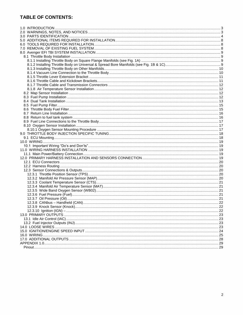
TABLE OF CONTENTS:
1.0 INTRODUCTION ..................................................................................................................................................................... 3 2.0 WARNINGS, NOTES, AND NOTICES .................................................................................................................................... 3 3.0 PARTS IDENTIFICATION ....................................................................................................................................................... 4 5.0 ADDITIONAL ITEMS REQUIRED FOR INSTALLATION ......................................................................................................... 8 6.0 TOOLS REQUIRED FOR INSTALLATION .............................................................................................................................. 8 7.0 REMOVAL OF EXISTING FUEL SYSTEM .............................................................................................................................. 8 8.0 Avenger EFI TBI SYSTEM INSTALLATION ............................................................................................................................ 9
8.1 Throttle Body Installation ..................................................................................................................................................... 9 8.1.1 Installing Throttle Body on Square Flange Manifolds (see Fig. 1A) ............................................................................... 9 8.1.2 Installing Throttle Body on Universal & Spread Bore Manifolds (see Fig. 1B & 1C)....................................................... 9 8.1.3 Installing Throttle Body on Other Manifolds .................................................................................................................. 10 8.1.4 Vacuum Line Connection to the Throttle Body ............................................................................................................. 10 8.1.5 Throttle Lever Extension Bracket ................................................................................................................................. 11 8.1.6 Throttle Cable and Kickdown Brackets......................................................................................................................... 11 8.1.7 Throttle Cable and Transmission Connectors .............................................................................................................. 12 8.1.8 Air Temperature Sensor Installation ............................................................................................................................ 12
8.2 Map Sensor Installation ..................................................................................................................................................... 12 8.3 Fuel Pump Installation ....................................................................................................................................................... 12 8.4 Dual Tank Installation ........................................................................................................................................................ 13 8.5 Fuel Pump Filter ................................................................................................................................................................. 15 8.6 Throttle Body Fuel Filter ..................................................................................................................................................... 15 8.7 Return Line Installation ...................................................................................................................................................... 16 8.8 Return to fuel tank system ................................................................................................................................................. 16 8.9 Fuel Line Connections to the Throttle Body ....................................................................................................................... 17 8.10 Oxygen Sensor Installation .............................................................................................................................................. 17
8.10.1 Oxygen Sensor Mounting Procedure ......................................................................................................................... 17 9.0 THROTTLE BODY INJECTION SPECIFIC TUNING ............................................................................................................. 18
9.1 ECU Mounting .................................................................................................................................................................... 18 10.0 WIRING ............................................................................................................................................................................... 19
10.1 Important Wiring “Do’s and Don’ts” .................................................................................................................................. 19 11.0 WIRING HARNESS INSTALLATION .................................................................................................................................. 19
11.1 Main Power/Battery Connection ....................................................................................................................................... 19 12.0 PRIMARY HARNESS INSTALLATION AND SENSORS CONNECTION ............................................................................ 19
12.1 ECU Connectors .............................................................................................................................................................. 20 12.2 Harness Routing .............................................................................................................................................................. 20 12.3 Sensor Connections & Outputs ........................................................................................................................................ 20
12.3.1 Throttle Position Sensor (TPS) .................................................................................................................................. 20 12.3.2 Manifold Air Pressure Sensor (MAP) ......................................................................................................................... 20 12.3.3 Coolant Temperature Sensor (CTS) .......................................................................................................................... 21 12.3.4 Manifold Air Temperature Sensor (MAT) ................................................................................................................... 21 12.3.5 Wide Band Oxygen Sensor (WB02) .......................................................................................................................... 21 12.3.6 Fuel Pressure (Fuel) .................................................................................................................................................. 21 12.3.7 Oil Pressure (Oil) ....................................................................................................................................................... 21 12.3.8 CANbus – Handheld (CAN) ....................................................................................................................................... 22 12.3.9 Knock Sensor (Knock) ............................................................................................................................................... 22 12.3.10 Ignition (IGN) – ........................................................................................................................................................ 22
13.0 PRIMARY OUTPUTS .......................................................................................................................................................... 23 13.1 Idle Air Control (IAC) ........................................................................................................................................................ 23 13.2 Fuel Injector Outputs (INJ) ............................................................................................................................................... 23
14.0 LOOSE WIRES ................................................................................................................................................................... 23 15.0 IGNITION/ENGINE SPEED INPUT ..................................................................................................................................... 24 16.0 WIRING ............................................................................................................................................................................... 25 17.0 ADDITIONAL OUTPUTS ..................................................................................................................................................... 28 APPENDIX 1.0.............................................................................................................................................................................. 29
Pinout ........................................................................................................................................................................................ 29
3
1.0 INTRODUCTION Holley Performance Products has written this manual for the installation of the Avenger EFI 2 BBL TBI fuel injection system.
This manual contains the information necessary for the hardware installation. Please read all the WARNINGS, NOTES and
TIPS, as they contain valuable information that can save you time and money. It is our intent to provide the best possible products for our customer; products that perform properly and satisfy your expectations. Should you need information or parts assistance, please contact our technical service department at 1-270-781-9741, Monday through Friday, 8 a.m. to 5 p.m. CST. By using this number, you may obtain any information and/or parts assistance that you may require. Please have the part number of the product you purchased when you call.
NOTE: Use adapter P/N 17-47 for Holley 2300/Motorcraft 2bbl flange. The 550-200 is a universal kit. Adapters are included for most square and spread bore manifolds. Engines that don’t use square bore or spread bore intakes will likely need an adapter fabricated. Many times the adapters included can be modified for other applications. The customer is responsible for this and any throttle and transmission linkage modifications necessary.
NOTE: This manual is for the hardware installation of an Avenger Throttle Body Fuel Injection System and instructions
specific to it. Instructions on wiring harness installation, software operation, sensor operation, and tuning is
contained in the supplied additional manual 199R10505.
WARNING! The Avenger EFI TBI system consists of a number of sophisticated components. Failure of any one
component does not constitute, nor does it justify, warranty of the complete system. Individual service
items are available for replacement of components. If assistance is required or if you need further
warranty clarification, you can call Holley Technical Service at the number shown above.
WARNING! To preserve warranty, these instructions must be read and followed thoroughly and completely before and
during installation. It is important that you become familiar with the parts and the installation of the
Avenger EFI TBI system before you begin. Failure to read and understand these instructions could result
in damage to Avenger EFI TBI components that are not covered by the warranty and could result in
serious personal injury and property damage.
WARNING! The oxygen sensor in this kit is designed to be used with ONLY unleaded fuels. Use of leaded fuels will
destroy the oxygen sensor and will result in incorrect exhaust gas oxygen readings and improper fuel
delivery. Failure to follow these directions does not constitute the right to a warranty claim.
WARNING! Failure to follow all of the above will result in an improper installation, which may lead to personal injury,
including death, and/or property damage. Improper installation and/or use of this or any Holley product
will void all warranties.
WARNING! Use of some RTV silicone sealers will destroy the oxygen sensor used with this product. Ensure the RTV
silicone sealant you use is compatible with oxygen sensor vehicles. This information should be found on
the oxygen sensor package.
2.0 WARNINGS, NOTES, AND NOTICES WARNING! For the safety and protection of you and others, only a trained mechanic having adequate fuel system
experience must perform the installation, adjustment, and repair. It is particularly important to remember
one of the very basic principles of safety: fuel vapors are heavier than air and tend to collect in low places
where an explosive fuel/air mixture may be ignited by any spark or flame resulting in property damage,
personal injury, and/or death. Extreme caution must be exercised to prevent spillage and thus eliminate
the formation of such fuel vapors.
WARNING! This type of work MUST be performed in a well-ventilated area. Do not smoke or have an open flame
present near gasoline vapors or an explosion may result.
4
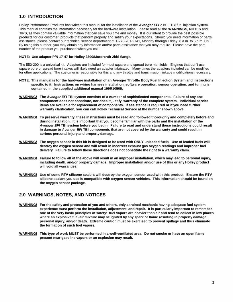
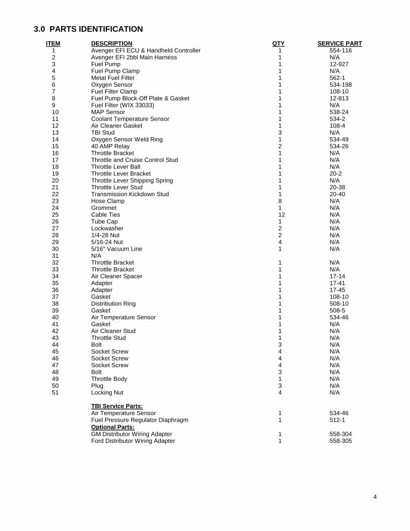
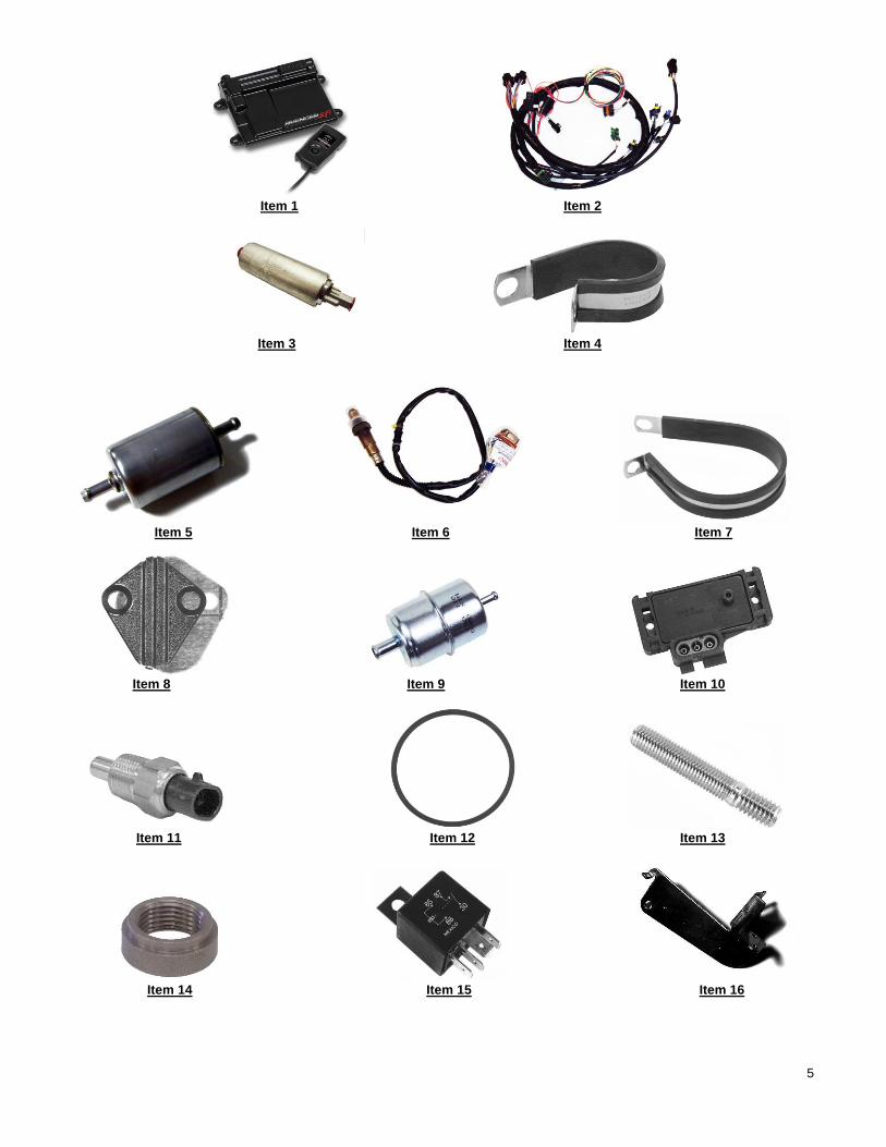
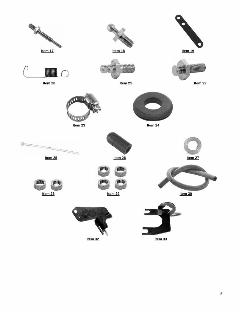
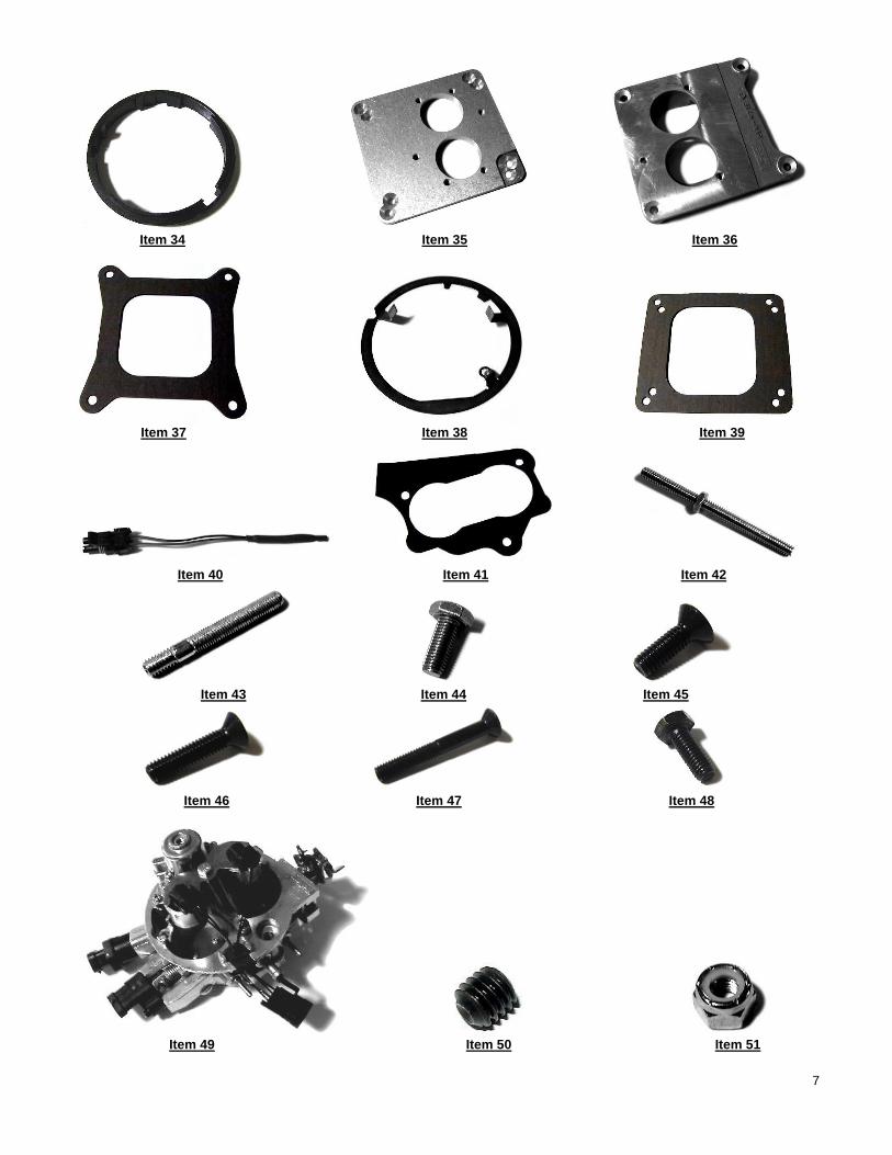
3.0 PARTS IDENTIFICATION
ITEM DESCRIPTION QTY SERVICE PART 1 Avenger EFI ECU & Handheld Controller 1 554-116 2 Avenger EFI 2bbl Main Harness 1 N/A 3 Fuel Pump 1 12-927 4 Fuel Pump Clamp 1 N/A 5 Metal Fuel Filter 1 562-1 6 Oxygen Sensor 1 534-198 7 Fuel Filter Clamp 1 108-10 8 Fuel Pump Block-Off Plate & Gasket 1 12-813 9 Fuel Filter (WIX 33033) 1 N/A 10 MAP Sensor 1 538-24 11 Coolant Temperature Sensor 1 534-2 12 Air Cleaner Gasket 1 108-4 13 TBI Stud 3 N/A 14 Oxygen Sensor Weld Ring 1 534-49 15 40 AMP Relay 2 534-26 16 Throttle Bracket 1 N/A 17 Throttle and Cruise Control Stud 1 N/A 18 Throttle Lever Ball 1 N/A 19 Throttle Lever Bracket 1 20-2 20 Throttle Lever Shipping Spring 1 N/A 21 Throttle Lever Stud 1 20-38 22 Transmission Kickdown Stud 1 20-40 23 Hose Clamp 8 N/A 24 Grommet 1 N/A 25 Cable Ties 12 N/A 26 Tube Cap 1 N/A 27 Lockwasher 2 N/A 28 1/4-28 Nut 2 N/A 29 5/16-24 Nut 4 N/A 30 5/16" Vacuum Line 1 N/A 31 N/A 32 Throttle Bracket 1 N/A 33 Throttle Bracket 1 N/A 34 Air Cleaner Spacer 1 17-14 35 Adapter 1 17-41 36 Adapter 1 17-45 37 Gasket 1 108-10 38 Distribution Ring 1 508-10 39 Gasket 1 508-5 40 Air Temperature Sensor 1 534-46 41 Gasket 1 N/A 42 Air Cleaner Stud 1 N/A 43 Throttle Stud 1 N/A 44 Bolt 3 N/A 45 Socket Screw 4 N/A 46 Socket Screw 4 N/A 47 Socket Screw 4 N/A 48 Bolt 3 N/A 49 Throttle Body 1 N/A 50 Plug 3 N/A 51 Locking Nut 4 N/A
TBI Service Parts: Air Temperature Sensor 1 534-46 Fuel Pressure Regulator Diaphragm 1 512-1
Optional Parts: GM Distributor Wiring Adapter 1 558-304 Ford Distributor Wiring Adapter 1 558-305
5
Item 1 Item 2
Item 3 Item 4
Item 5 Item 6 Item 7
Item 8 Item 9 Item 10
Item 11 Item 12 Item 13
Item 14 Item 15 Item 16
6
Item 17 Item 18 Item 19
Item 20 Item 21 Item 22
Item 23 Item 24
Item 25 Item 26 Item 27
Item 28 Item 29 Item 30
Item 32 Item 33
7
Item 34 Item 35 Item 36
Item 37 Item 38 Item 39
Item 40 Item 41 Item 42
Item 43 Item 44 Item 45
Item 46 Item 47 Item 48
Item 49 Item 50 Item 51
8
5.0 ADDITIONAL ITEMS REQUIRED FOR INSTALLATION
3/8" fuel hose (must meet SAE J30) 5/16" fuel hose (must meet SAE J30)
5/16" steel fuel line (must meet SAE J526) 0-30 psi fuel gauge or Holley Pressure Transducer
Tee fitting for fuel gauge If an intake adapter other than the included square bore and spread bore adapters are needed, one must be fabricated by the customer. It is possible a new throttle and transmission cable bracket may be necessary.
6.0 TOOLS REQUIRED FOR INSTALLATION
Standard wrench set Small blade screwdriver 5/32” Allen wrench
Medium blade screwdriver #2 Phillips screwdriver Digital Volt-Ohm meter
Drill and assorted bit sizes Hole saw (2”) Terminal crimping tool
Engine tachometer 10” adjustable wrench Utility knife
Factory Service Manual for your vehicle
An assistant is necessary for some installation and adjustment procedures and should be present for safety reasons.
7.0 REMOVAL OF EXISTING FUEL SYSTEM 1. Disconnect the battery and remove the air cleaner. 2. Before disconnecting any vacuum hoses, it is a good idea to sketch out the vacuum hose routing. Using masking tape
and a permanent marker, mark all the vacuum hoses, vacuum sources, and ports before removing the old fuel delivery system.
3. Remove and discard the fuel line that connects the fuel delivery system from the fuel pump. This will not be needed in the
installation. 4. Disconnect and plug the inlet fuel line that runs from the gas tank to the fuel pump. This will prevent fuel spillage and
foreign matter or dirt from entering the fuel line.
DANGER! BEFORE DISCONNECTING OR REMOVING FUEL LINES, ENSURE THE ENGINE IS COLD. DO NOT SMOKE.
EXTINGUISH ALL OPEN FLAMES. AN OPEN FLAME, SPARK, OR EXTREME HEAT NEAR GASOLINE CAN
RESULT IN A FIRE OR EXPLOSION CAUSING PROPERTY DAMAGE, SERIOUS INJURY, AND/OR DEATH. 5. The fuel delivery system can now be removed. Holley recommends removing the mechanical fuel pump, if so equipped,
and blocking-off the fuel pump mount using the provided fuel pump block off plate. The Avenger EFI TBI system kit includes a block-off plate that will fit small and big block Chevrolet and Chrysler engines. If the block-off plate does not fit your engine, a block-off plate may have to be purchased from a local performance parts supplier.
6. If required, replace the intake manifold at this time. Proceed to step seven if this is not required. TO USE THE INCLUDED
INTAKE ADAPTERS, A 4-BARREL STOCK OR AFTERMARKET INTAKE MANIFOLD IS REQUIRED. 7. Place clean shop towels or rags into the manifold opening to prevent dirt or debris from entering the engine. Keep
exposed ends of the vacuum and fuel lines free from dirt.
WARNING! Failure to cover the intake opening with a clean towel could result in dirt or debris entering the engine.
Dirt or debris in the induction system can cause engine damage, which may necessitate a complete
engine overhaul.
8. Remove all traces of the old gasket material from the TBI mounting flange. DO NOT gouge the intake manifold sealing surface during removal of old gasket material. Failure to remove all traces of the old gasket material will result in vacuum leaks that will be difficult to detect later. Sealing flanges must be clean and dry before installation.
9. Remove the shop towels from the intake and vacuum out the intake channel to ensure no dirt or debris is left in the intake
system. Place a shop towel over the entire intake opening until you are ready to install the new Avenger EFI TBI.
9
8.0 Avenger EFI TBI SYSTEM INSTALLATION
8.1 Throttle Body Installation
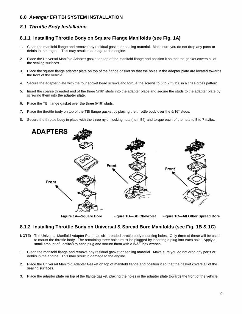
8.1.1 Installing Throttle Body on Square Flange Manifolds (see Fig. 1A) 1. Clean the manifold flange and remove any residual gasket or sealing material. Make sure you do not drop any parts or
debris in the engine. This may result in damage to the engine. 2. Place the Universal Manifold Adapter gasket on top of the manifold flange and position it so that the gasket covers all of
the sealing surfaces. 3. Place the square flange adapter plate on top of the flange gasket so that the holes in the adapter plate are located towards
the front of the vehicle. 4. Secure the adapter plate with the four socket head screws and torque the screws to 5 to 7 ft./lbs. in a criss-cross pattern. 5. Insert the coarse threaded end of the three 5/16” studs into the adapter place and secure the studs to the adapter plate by
screwing them into the adapter plate. 6. Place the TBI flange gasket over the three 5/16” studs. 7. Place the throttle body on top of the TBI flange gasket by placing the throttle body over the 5/16” studs. 8. Secure the throttle body in place with the three nylon locking nuts (item 54) and torque each of the nuts to 5 to 7 ft./lbs.
Figure 1A—Square Bore Figure 1B—SB Chevrolet Figure 1C—All Other Spread Bore
8.1.2 Installing Throttle Body on Universal & Spread Bore Manifolds (see Fig. 1B & 1C)
NOTE: The Universal Manifold Adapter Plate has six threaded throttle body mounting holes. Only three of these will be used to mount the throttle body. The remaining three holes must be plugged by inserting a plug into each hole. Apply a small amount of Loctite® to each plug and secure them with a 5/32” hex wrench.
1. Clean the manifold flange and remove any residual gasket or sealing material. Make sure you do not drop any parts or
debris in the engine. This may result in damage to the engine. 2. Place the Universal Manifold Adapter Gasket on top of manifold flange and position it so that the gasket covers all of the
sealing surfaces. 3. Place the adapter plate on top of the flange gasket, placing the holes in the adapter plate towards the front of the vehicle.
10
NOTE: On Small Block Chevrolet applications with stock intake manifolds, the adapter plate should be installed so that the adapter plate’s bores are located over the large secondary bores on the manifold. If you experience problems with the fit of the universal adapter plate, Holley recommends the installation of part #17-6, Spread Bore Adapter, underneath the Universal adapter plate. Use Holley adapter 17-47 for Holley 2300/Motorcraft 2 bbl flange.
NOTE: If you are using an aftermarket manifold with a Small Block Chevrolet application, position the adapter plate bores so that they are located towards the front of the intake manifold. On all other applications, except for those described, position the adapter plate bores so that they are located towards the front of the intake manifold.
NOTE: On stock Big Block Chevrolet applications, the throttle body must be mounted towards the front of the manifold, even though the bore holes will not line up correctly. This is necessary to prevent the front cylinders from running too lean. If you experience problems with the fit of the universal adapter plate, Holley recommends the installation of part #17-6, Spread Bore Adapter, underneath the Universal Adapter Plate.
4. Secure the adapter plate to the manifold with the four socket-head screws and torque them 5 to 7 ft./lbs. (60-84 in./lbs.) in
a criss-cross pattern. 5. Insert the coarse threaded end of the three 5/16” studs into the adapter plate and secure the studs to the adapter plate by
screwing the studs into the adapter plate. 6. Place the TBI flange gasket over the three 5/16” studs. 7. Place the throttle body on top of the TBI flange gasket by placing the throttle body over the 5/16” studs. 8. Secure the throttle body in place with the three locking nuts and torque each to 5-7 ft./lbs.
8.1.3 Installing Throttle Body on Other Manifolds This system can be installed on any 4, 6, or 8 cylinder even fire engine. If an adapter plate is not available for the application, an existing spacer will have to be modified or a new one made. In many cases one of the existing adapter plates can be modified to fit other engines. If this does not work, a custom adapter will have to be machined.
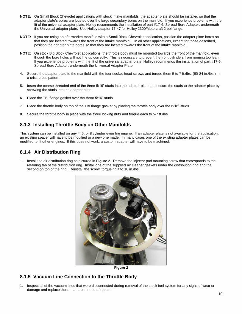
8.1.4 Air Distribution Ring
1. Install the air distribution ring as pictured in Figure 2. Remove the injector pod mounting screw that corresponds to the retaining tab of the distribution ring. Install one of the supplied air cleaner gaskets under the distribution ring and the second on top of the ring. Reinstall the screw, torqueing it to 18 in./lbs.
Figure 2
8.1.5 Vacuum Line Connection to the Throttle Body 1. Inspect all of the vacuum lines that were disconnected during removal of the stock fuel system for any signs of wear or
damage and replace those that are in need of repair.
11
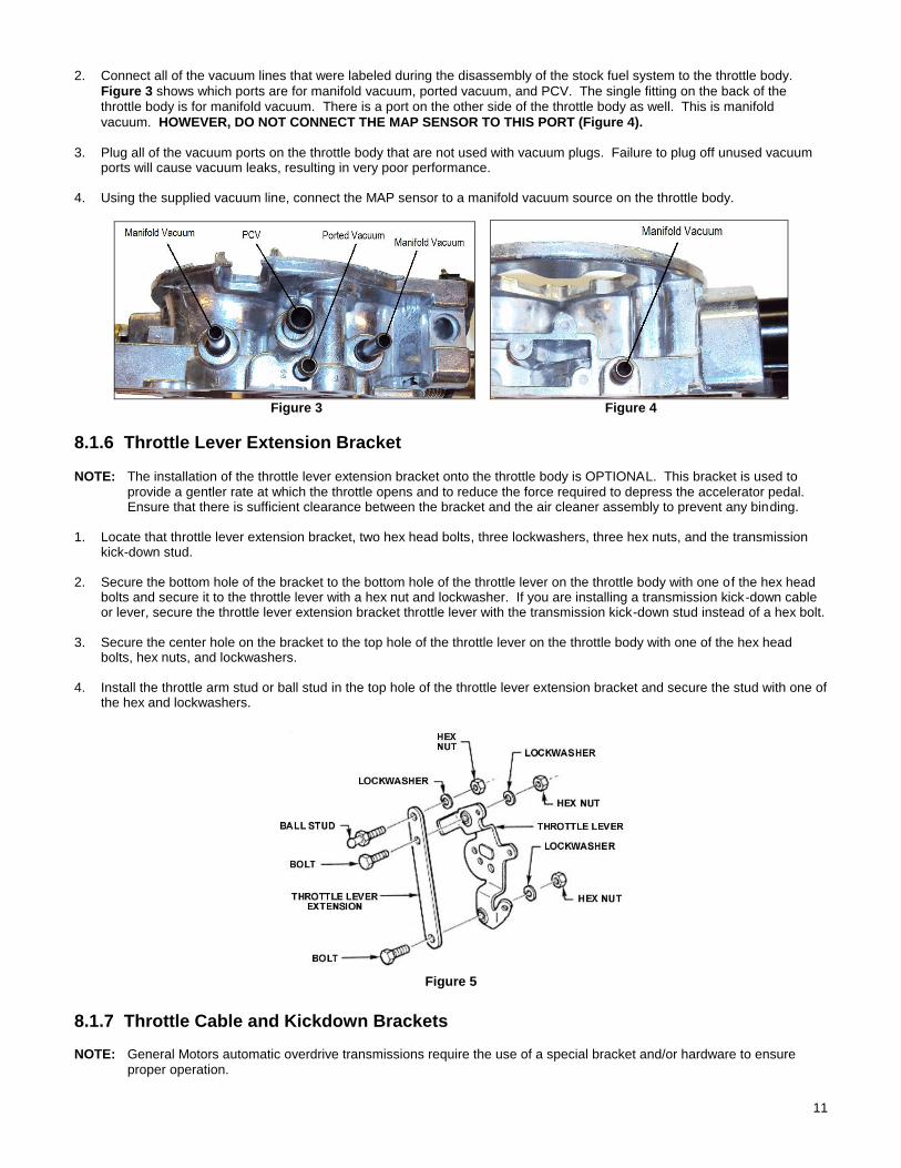
2. Connect all of the vacuum lines that were labeled during the disassembly of the stock fuel system to the throttle body.
Figure 3 shows which ports are for manifold vacuum, ported vacuum, and PCV. The single fitting on the back of the throttle body is for manifold vacuum. There is a port on the other side of the throttle body as well. This is manifold
vacuum. HOWEVER, DO NOT CONNECT THE MAP SENSOR TO THIS PORT (Figure 4). 3. Plug all of the vacuum ports on the throttle body that are not used with vacuum plugs. Failure to plug off unused vacuum
ports will cause vacuum leaks, resulting in very poor performance. 4. Using the supplied vacuum line, connect the MAP sensor to a manifold vacuum source on the throttle body.
Figure 3 Figure 4
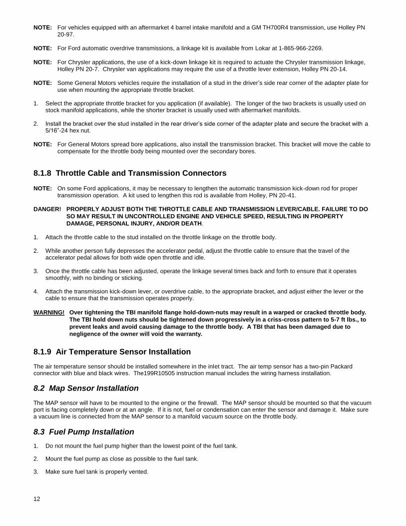
8.1.6 Throttle Lever Extension Bracket
NOTE: The installation of the throttle lever extension bracket onto the throttle body is OPTIONAL. This bracket is used to provide a gentler rate at which the throttle opens and to reduce the force required to depress the accelerator pedal. Ensure that there is sufficient clearance between the bracket and the air cleaner assembly to prevent any binding.
1. Locate that throttle lever extension bracket, two hex head bolts, three lockwashers, three hex nuts, and the transmission
kick-down stud. 2. Secure the bottom hole of the bracket to the bottom hole of the throttle lever on the throttle body with one of the hex head
bolts and secure it to the throttle lever with a hex nut and lockwasher. If you are installing a transmission kick-down cable or lever, secure the throttle lever extension bracket throttle lever with the transmission kick-down stud instead of a hex bolt.
3. Secure the center hole on the bracket to the top hole of the throttle lever on the throttle body with one of the hex head
bolts, hex nuts, and lockwashers. 4. Install the throttle arm stud or ball stud in the top hole of the throttle lever extension bracket and secure the stud with one of
the hex and lockwashers.
Figure 5
8.1.7 Throttle Cable and Kickdown Brackets
NOTE: General Motors automatic overdrive transmissions require the use of a special bracket and/or hardware to ensure proper operation.
12
NOTE: For vehicles equipped with an aftermarket 4 barrel intake manifold and a GM TH700R4 transmission, use Holley PN 20-97.
NOTE: For Ford automatic overdrive transmissions, a linkage kit is available from Lokar at 1-865-966-2269.
NOTE: For Chrysler applications, the use of a kick-down linkage kit is required to actuate the Chrysler transmission linkage, Holley PN 20-7. Chrysler van applications may require the use of a throttle lever extension, Holley PN 20-14.
NOTE: Some General Motors vehicles require the installation of a stud in the driver’s side rear corner of the adapter plate for use when mounting the appropriate throttle bracket.
1. Select the appropriate throttle bracket for you application (if available). The longer of the two brackets is usually used on
stock manifold applications, while the shorter bracket is usually used with aftermarket manifolds. 2. Install the bracket over the stud installed in the rear driver’s side corner of the adapter plate and secure the bracket with a
5/16”-24 hex nut.
NOTE: For General Motors spread bore applications, also install the transmission bracket. This bracket will move the cable to compensate for the throttle body being mounted over the secondary bores.
8.1.8 Throttle Cable and Transmission Connectors
NOTE: On some Ford applications, it may be necessary to lengthen the automatic transmission kick-down rod for proper transmission operation. A kit used to lengthen this rod is available from Holley, PN 20-41.
DANGER! PROPERLY ADJUST BOTH THE THROTTLE CABLE AND TRANSMISSION LEVER/CABLE. FAILURE TO DO
SO MAY RESULT IN UNCONTROLLED ENGINE AND VEHICLE SPEED, RESULTING IN PROPERTY
DAMAGE, PERSONAL INJURY, AND/OR DEATH. 1. Attach the throttle cable to the stud installed on the throttle linkage on the throttle body. 2. While another person fully depresses the accelerator pedal, adjust the throttle cable to ensure that the travel of the
accelerator pedal allows for both wide open throttle and idle. 3. Once the throttle cable has been adjusted, operate the linkage several times back and forth to ensure that it operates
smoothly, with no binding or sticking. 4. Attach the transmission kick-down lever, or overdrive cable, to the appropriate bracket, and adjust either the lever or the
cable to ensure that the transmission operates properly.
WARNING! Over tightening the TBI manifold flange hold-down-nuts may result in a warped or cracked throttle body.
The TBI hold down nuts should be tightened down progressively in a criss-cross pattern to 5-7 ft lbs., to
prevent leaks and avoid causing damage to the throttle body. A TBI that has been damaged due to
negligence of the owner will void the warranty.
8.1.9 Air Temperature Sensor Installation The air temperature sensor should be installed somewhere in the inlet tract. The air temp sensor has a two-pin Packard connector with blue and black wires. The199R10505 instruction manual includes the wiring harness installation.
8.2 Map Sensor Installation The MAP sensor will have to be mounted to the engine or the firewall. The MAP sensor should be mounted so that the vacuum port is facing completely down or at an angle. If it is not, fuel or condensation can enter the sensor and damage it. Make sure a vacuum line is connected from the MAP sensor to a manifold vacuum source on the throttle body.
8.3 Fuel Pump Installation
1. Do not mount the fuel pump higher than the lowest point of the fuel tank.
2. Mount the fuel pump as close as possible to the fuel tank.
3. Make sure fuel tank is properly vented.
13
DANGER! NEVER GET UNDER A VEHICLE SUPPORTED ONLY BY A JACK. SERIOUS INJURY OR DEATH CAN
RESULT FROM VEHICLES FALLING OFF OF JACKS. BEFORE WORKING UNDERNEATH A VEHICLE,
SUPPORT IT SOLIDLY WITH JACK STANDS.
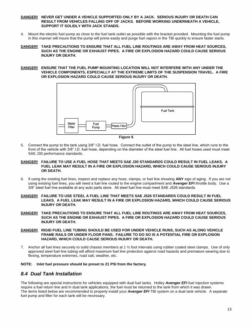
4. Mount the electric fuel pump as close to the fuel tank outlet as possible with the bracket provided. Mounting the fuel pump in this manner will insure that the pump will prime easily and purge fuel vapors in the TBI quickly to ensure faster starts.
DANGER! TAKE PRECAUTIONS TO ENSURE THAT ALL FUEL LINE ROUTINGS ARE AWAY FROM HEAT SOURCES,
SUCH AS THE ENGINE OR EXHAUST PIPES. A FIRE OR EXPLOSION HAZARD COULD CAUSE SERIOUS
INJURY OR DEATH.
DANGER! ENSURE THAT THE FUEL PUMP MOUNTING LOCATION WILL NOT INTERFERE WITH ANY UNDER THE
VEHICLE COMPONENTS, ESPECIALLY AT THE EXTREME LIMITS OF THE SUSPENSION TRAVEL. A FIRE
OR EXPLOSION HAZARD COULD CAUSE SERIOUS INJURY OR DEATH.
Figure 6
5. Connect the pump to the tank using 3/8” I.D. fuel hose. Connect the outlet of the pump to the steel line, which runs to the front of the vehicle with 3/8” I.D. fuel hose, depending on the diameter of the steel fuel line. All fuel hoses used must meet SAE J30 performance standards.
DANGER! FAILURE TO USE A FUEL HOSE THAT MEETS SAE J30 STANDARDS COULD RESULT IN FUEL LEAKS. A
FUEL LEAK MAY RESULT IN A FIRE OR EXPLOSION HAZARD, WHICH COULD CAUSE SERIOUS INJURY
OR DEATH.
6. If using the existing fuel lines, inspect and replace any hose, clamps, or fuel line showing ANY sign of aging. If you are not
using existing fuel lines, you will need a fuel line routed to the engine compartment and Avenger EFI throttle body. Use a 3/8” steel fuel line available at any auto parts store. All steel fuel line must meet SAE J526 standards.
DANGER! FAILURE TO USE STEEL A FUEL LINE THAT MEETS SAE J526 STANDARDS COULD RESULT IN FUEL
LEAKS. A FUEL LEAK MAY RESULT IN A FIRE OR EXPLOSION HAZARD, WHICH COULD CAUSE SERIOUS
INJURY OR DEATH.
DANGER! TAKE PRECAUTIONS TO ENSURE THAT ALL FUEL LINE ROUTINGS ARE AWAY FROM HEAT SOURCES,
SUCH AS THE ENGINE OR EXHAUST PIPES. A FIRE OR EXPLOSION HAZARD COULD CAUSE SERIOUS
INJURY OR DEATH.
DANGER! RIGID FUEL LINE TUBING SHOULD BE USED FOR UNDER VEHICLE RUNS, SUCH AS ALONG VEHICLE
FRAME RAILS OR UNDER FLOOR PANS. FAILURE TO DO SO IS A POTENTIAL FIRE OR EXPLOSION
HAZARD, WHICH COULD CAUSE SERIOUS INJURY OR DEATH.
7. Anchor all fuel lines securely to solid chassis members at 1 ½ foot intervals using rubber coated steel clamps. Use of only approved steel fuel line tubing will afford maximum fuel line protection against road hazards and premature wearing due to flexing, temperature extremes, road salt, weather, etc.
NOTE: Inlet fuel pressure should be preset to 21 PSI from the factory.
8.4 Dual Tank Installation The following are special instructions for vehicles equipped with dual fuel tanks. Holley Avenger EFI fuel injection systems require a fuel return line and in dual tank applications, the fuel must be returned to the tank from which it was drawn. The items listed below are recommended to properly install your Avenger EFI TBI system on a dual tank vehicle. A separate fuel pump and filter for each tank will be necessary.
14
Holley offers these items in a kit, part number 534-37.
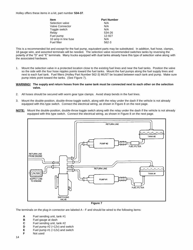
Item Part Number Selection valve N/A Valve Connector N/A Toggle switch N/A Relay 534-26 Fuel pump 12-927 10 amp in line fuse N/A Fuel filter 562-3 This is a recommended list and except for the fuel pump, equivalent parts may be substituted. In addition, fuel hose, clamps, 18 gauge wire, and assorted terminals will be needed. The selection valve recommended switches tanks by reversing the polarity of the “D” and “E” terminals. Many trucks equipped with dual tanks already have this type of selection valve along with the associated hardware. 1. Mount the selection valve in a protected location close to the existing fuel lines and near the fuel tanks. Position the valve
so the side with the four hose nipples points toward the fuel tanks. Mount the fuel pumps along the fuel supply lines and next to each fuel tank. Fuel filters (Holley Part Number 562-3) MUST be located between each tank and pump. Make sure pump inlets point toward the tanks. (See Figure 7).
WARNING! The supply and return hoses from the same tank must be connected next to each other on the selection
valve. 2. All hoses should be secured with worm gear type clamps. Avoid sharp bends in the fuel lines. 3. Mount the double-position, double-throw toggle switch, along with the relay under the dash if the vehicle is not already
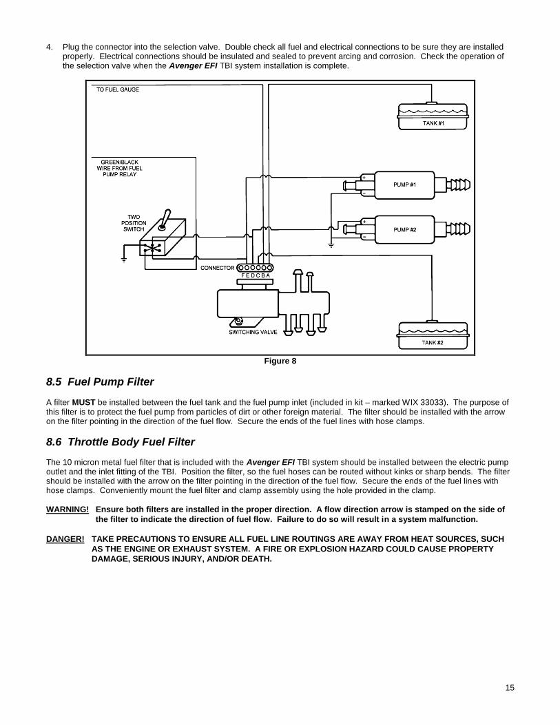
equipped with this type switch. Connect the electrical wiring, as shown in Figure 8 on the next page.
NOTE: Mount the double-position, double-throw toggle switch along with the relay under the dash if the vehicle is not already equipped with this type switch. Connect the electrical wiring, as shown in Figure 8 on the next page.
Figure 7
The terminals on the plug-in connector are labeled A - F and should be wired to the following items:
A Fuel sending unit, tank #1
B Fuel gauge at dash
C Fuel sending unit, tank #2
D Fuel pump #2 (+12v) and switch
E Fuel pump #1 (+12v) and switch
F Not used
15
4. Plug the connector into the selection valve. Double check all fuel and electrical connections to be sure they are installed
properly. Electrical connections should be insulated and sealed to prevent arcing and corrosion. Check the operation of the selection valve when the Avenger EFI TBI system installation is complete.
Figure 8
8.5 Fuel Pump Filter
A filter MUST be installed between the fuel tank and the fuel pump inlet (included in kit – marked WIX 33033). The purpose of this filter is to protect the fuel pump from particles of dirt or other foreign material. The filter should be installed with the arrow on the filter pointing in the direction of the fuel flow. Secure the ends of the fuel lines with hose clamps.
8.6 Throttle Body Fuel Filter The 10 micron metal fuel filter that is included with the Avenger EFI TBI system should be installed between the electric pump outlet and the inlet fitting of the TBI. Position the filter, so the fuel hoses can be routed without kinks or sharp bends. The filter should be installed with the arrow on the filter pointing in the direction of the fuel flow. Secure the ends of the fuel lines with hose clamps. Conveniently mount the fuel filter and clamp assembly using the hole provided in the clamp.
WARNING! Ensure both filters are installed in the proper direction. A flow direction arrow is stamped on the side of
the filter to indicate the direction of fuel flow. Failure to do so will result in a system malfunction.
DANGER! TAKE PRECAUTIONS TO ENSURE ALL FUEL LINE ROUTINGS ARE AWAY FROM HEAT SOURCES, SUCH
AS THE ENGINE OR EXHAUST SYSTEM. A FIRE OR EXPLOSION HAZARD COULD CAUSE PROPERTY
DAMAGE, SERIOUS INJURY, AND/OR DEATH.
16
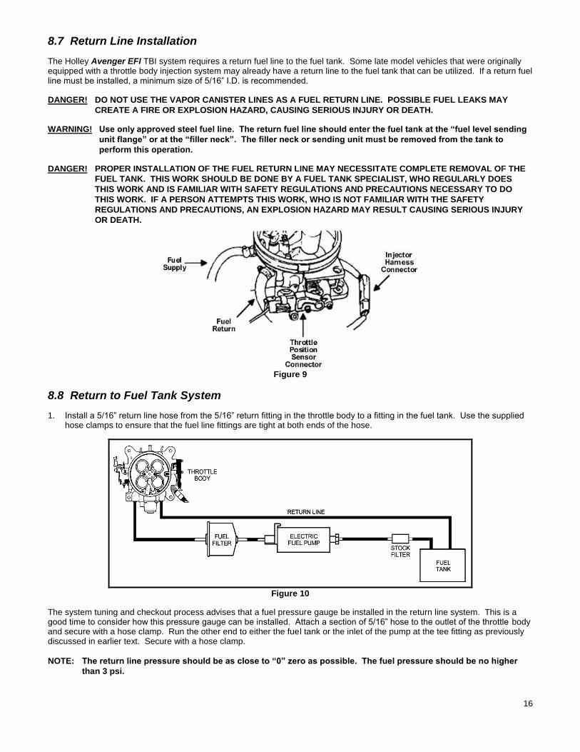
8.7 Return Line Installation
The Holley Avenger EFI TBI system requires a return fuel line to the fuel tank. Some late model vehicles that were originally equipped with a throttle body injection system may already have a return line to the fuel tank that can be utilized. If a return fuel line must be installed, a minimum size of 5/16” I.D. is recommended.
DANGER! DO NOT USE THE VAPOR CANISTER LINES AS A FUEL RETURN LINE. POSSIBLE FUEL LEAKS MAY
CREATE A FIRE OR EXPLOSION HAZARD, CAUSING SERIOUS INJURY OR DEATH.
WARNING! Use only approved steel fuel line. The return fuel line should enter the fuel tank at the “fuel level sending
unit flange” or at the “filler neck”. The filler neck or sending unit must be removed from the tank to
perform this operation.
DANGER! PROPER INSTALLATION OF THE FUEL RETURN LINE MAY NECESSITATE COMPLETE REMOVAL OF THE
FUEL TANK. THIS WORK SHOULD BE DONE BY A FUEL TANK SPECIALIST, WHO REGULARLY DOES
THIS WORK AND IS FAMILIAR WITH SAFETY REGULATIONS AND PRECAUTIONS NECESSARY TO DO
THIS WORK. IF A PERSON ATTEMPTS THIS WORK, WHO IS NOT FAMILIAR WITH THE SAFETY
REGULATIONS AND PRECAUTIONS, AN EXPLOSION HAZARD MAY RESULT CAUSING SERIOUS INJURY
OR DEATH.
Figure 9
8.8 Return to Fuel Tank System
1. Install a 5/16” return line hose from the 5/16” return fitting in the throttle body to a fitting in the fuel tank. Use the supplied hose clamps to ensure that the fuel line fittings are tight at both ends of the hose.
Figure 10
The system tuning and checkout process advises that a fuel pressure gauge be installed in the return line system. This is a good time to consider how this pressure gauge can be installed. Attach a section of 5/16” hose to the outlet of the throttle body and secure with a hose clamp. Run the other end to either the fuel tank or the inlet of the pump at the tee fitting as previously discussed in earlier text. Secure with a hose clamp.
NOTE: The return line pressure should be as close to “0” zero as possible. The fuel pressure should be no higher
than 3 psi.
17
8.9 Fuel Line Connections to the Throttle Body
WARNING! The fuel pressure in the fuel return line MUST be less than 3 PSI for the system to operate properly. Fuel
return line pressure of 3 PSI or more will result from the return line being too small, a restriction in the
line, or too many bends. Return fuel pressure in excess of 3 PSI may result in an excessive fuel condition
(flooding) which may cause stalling or hard starting. 1. Locate the fuel inlet fitting on the throttle body. It is located on the driver’s side of the vehicle with the fuel fittings facing the
rear of the vehicle. 2. Attach the fuel supply line to the fuel inlet fitting on the throttle body with 3/8” ID J30 fuel hose and secure the fuel supply
line to the fitting with a hose clamp. 3. Locate the fuel outlet fitting on the throttle body. It is located on the passenger side of the vehicle with the fuel fitting facing
the rear of the vehicle. 4. Attach the fuel return line to the fuel return outlet fitting on the throttle body with 5/16” ID J30 fuel hose and secure the fuel
return line to the fitting with a hose clamp.
8.10 Oxygen Sensor Installation
It is recommended to mount the oxygen sensor as close as possible, where one bank of cylinders merge together. If an OEM mounting location is available, use it. With stock cast iron manifolds, the sensor can be mounted in the exhaust pipe, right after the cast iron manifold in the exhaust pipe or possibly in the end of the manifold itself. If the vehicle has “shorty” headers, the sensor can be mounted in the collector of the headers.
If the vehicle has long tube headers, the sensor can be mounted in the collector, but the temperature will likely be too low at idle for proper operation. A fix for this, if proper closed loop operation does not occur, is to run open loop at lower engine speeds, until enough heat is available for proper operation. This is programmable in the ECU. Other factors, such as camshaft specifications, will affect how well closed loop operation occurs at low engine speeds and loads.
8.10.1 Oxygen Sensor Mounting Procedure
NOTE: Never run the engine with the oxygen sensor installed if it is not plugged in and powered by the ECU, or it will be damaged. If you need to plug the hole temporarily, use an O2 sensor plug or a spark plug with an 18mm thread.
NOTE: Someone with experience in welding exhaust systems should install the oxygen sensor boss. Any competent exhaust shop is able to perform this task at a minimum cost.
WARNING! Use only unleaded fuel when operating an oxygen sensor. Use of leaded fuels will destroy the oxygen
sensor and will result in incorrect exhaust gas oxygen-content readings.
WARNING! Use of some RTV silicone sealers will destroy the oxygen sensor used with this product. Ensure the RTV
silicone sealant you use is compatible with oxygen sensor vehicles. This information should be found on
the oxygen sensor package.
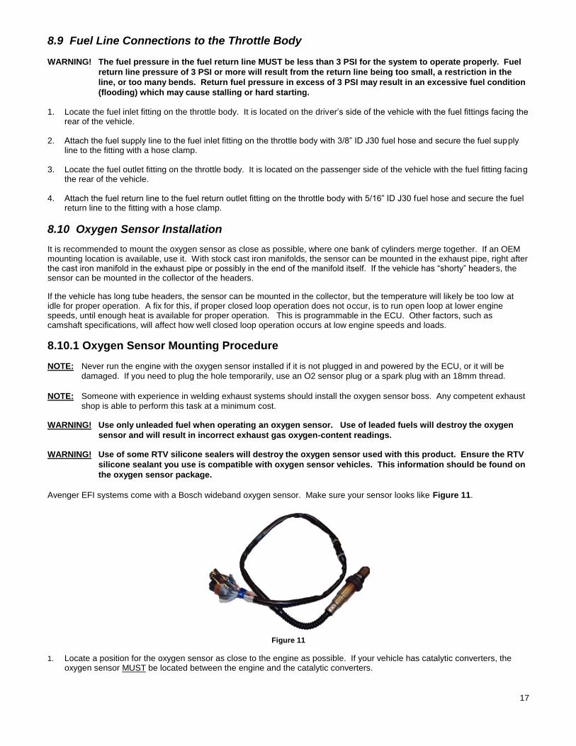
Avenger EFI systems come with a Bosch wideband oxygen sensor. Make sure your sensor looks like Figure 11.
Figure 11
1. Locate a position for the oxygen sensor as close to the engine as possible. If your vehicle has catalytic converters, the oxygen sensor MUST be located between the engine and the catalytic converters.
18
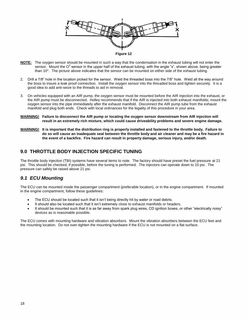
Figure 12
NOTE: The oxygen sensor should be mounted in such a way that the condensation in the exhaust tubing will not enter the sensor. Mount the O
2 sensor in the upper half of the exhaust tubing, with the angle “x”, shown above, being greater
than 10°. The picture above indicates that the sensor can be mounted on either side of the exhaust tubing.
2. Drill a 7/8” hole in the location picked for the sensor. Weld the threaded boss into the 7/8” hole. Weld all the way around
the boss to insure a leak proof connection. Install the oxygen sensor into the threaded boss and tighten securely. It is a good idea to add anti-seize to the threads to aid in removal.
3. On vehicles equipped with an AIR pump, the oxygen sensor must be mounted before the AIR injection into the exhaust, or
the AIR pump must be disconnected. Holley recommends that if the AIR is injected into both exhaust manifolds; mount the oxygen sensor into the pipe immediately after the exhaust manifold. Disconnect the AIR pump tube from the exhaust manifold and plug both ends. Check with local ordinances for the legality of this procedure in your area.
WARNING! Failure to disconnect the AIR pump or locating the oxygen sensor downstream from AIR injection will
result in an extremely rich mixture, which could cause driveability problems and severe engine damage.
WARNING! It is important that the distribution ring is properly installed and fastened to the throttle body. Failure to
do so will cause an inadequate seal between the throttle body and air cleaner and may be a fire hazard in
the event of a backfire. Fire hazard can result in property damage, serious injury, and/or death.
9.0 THROTTLE BODY INJECTION SPECIFIC TUNING The throttle body injection (TBI) systems have several items to note. The factory should have preset the fuel pressure at 21 psi. This should be checked, if possible, before the tuning is performed. The injectors can operate down to 10 psi. The pressure can safely be raised above 21 psi.
9.1 ECU Mounting The ECU can be mounted inside the passenger compartment (preferable location), or in the engine compartment. If mounted in the engine compartment, follow these guidelines:
The ECU should be located such that it isn’t being directly hit by water or road debris.
It should also be located such that it isn’t extremely close to exhaust manifolds or headers.
It should be mounted such that it is as far away from spark plug wires, CD ignition boxes, or other “electrically noisy” devices as is reasonable possible.
The ECU comes with mounting hardware and vibration absorbers. Mount the vibration absorbers between the ECU feet and the mounting location. Do not over-tighten the mounting hardware if the ECU is not mounted on a flat surface.
19
10.0 WIRING The following overviews how to properly install the wiring harnesses for this system.
10.1 Important Wiring “Do’s and Don’ts”
An EFI system depends heavily on being supplied a clean and constant voltage source. The grounds of an electrical system are just as important as the power side.
Avenger ECU’s contain multiple processing devices that require clean power and ground sources. The wiring harnesses for them must be installed in such a manner that they are separated from “dirty” power and ground sources.
DO’S
Install the main power and ground directly to the battery.
Keep sensor wiring away from high voltage or “noisy/dirty” components and wiring, especially secondary ignition wiring (plug wires), ignition boxes and associated wiring.
Properly solder and heat shrink any wire connections.
It is critical that the engine has a proper ground connection to the battery and chassis.
DON’TS
NEVER run high voltage or “noisy/dirty” wires in parallel (bundle/loom together) with any EFI sensor wiring. If wires need to cross, try to do so at an angle.
Do not use the electric fan outputs to directly power a fan. They must only trigger a relay.
Do not use improper crimping tools.
Don’t use things like “t-taps”, etc. Use solder and heat shrink.
It is never recommended to splice/share signal wires (such as TPS, etc) between different electronic control units.
11.0 WIRING HARNESS INSTALLATION
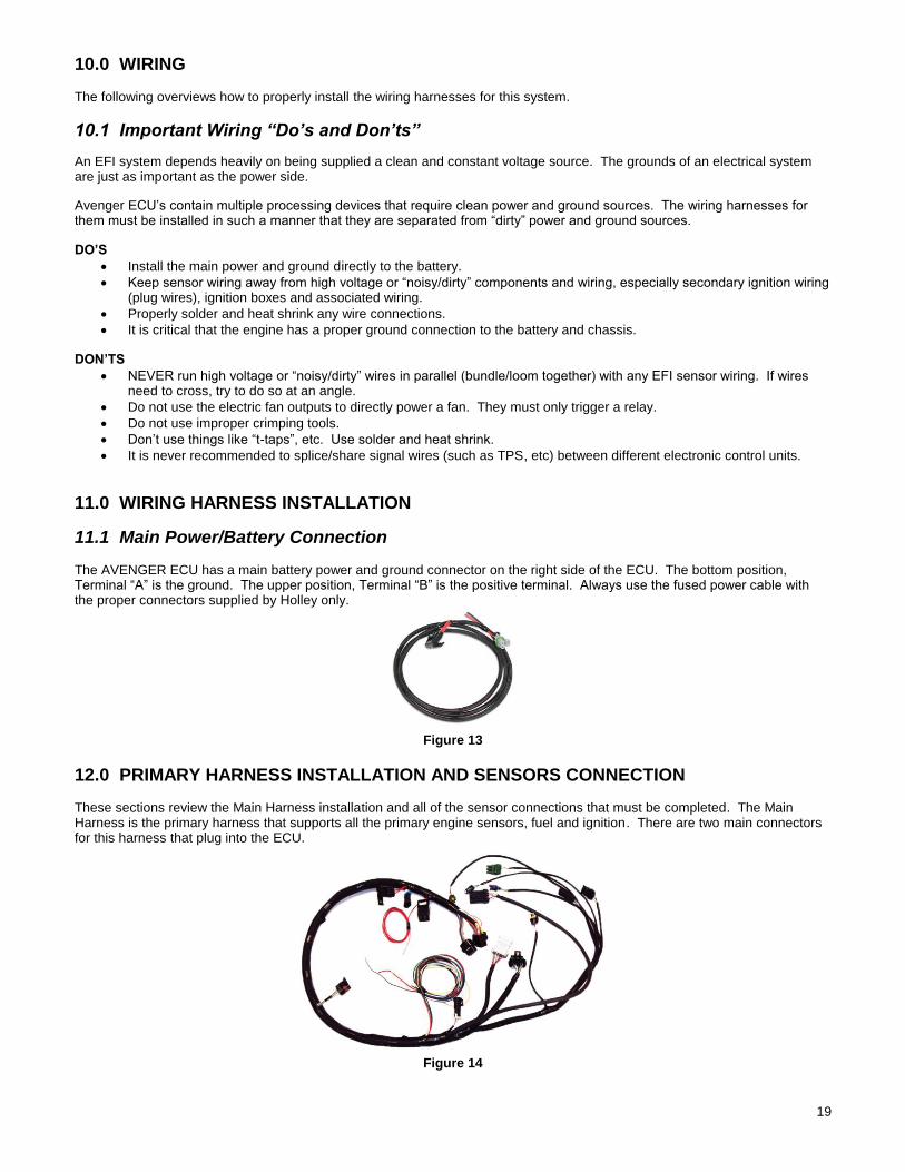
11.1 Main Power/Battery Connection The AVENGER ECU has a main battery power and ground connector on the right side of the ECU. The bottom position, Terminal “A” is the ground. The upper position, Terminal “B” is the positive terminal. Always use the fused power cable with the proper connectors supplied by Holley only.
Figure 13
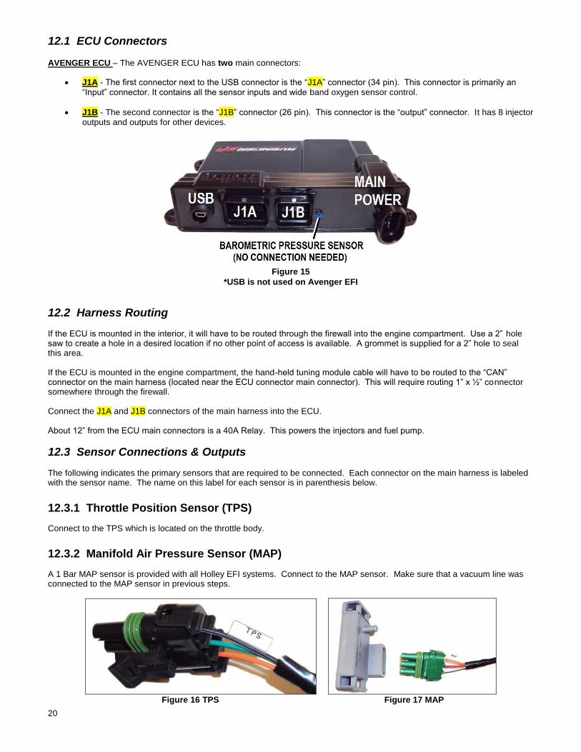
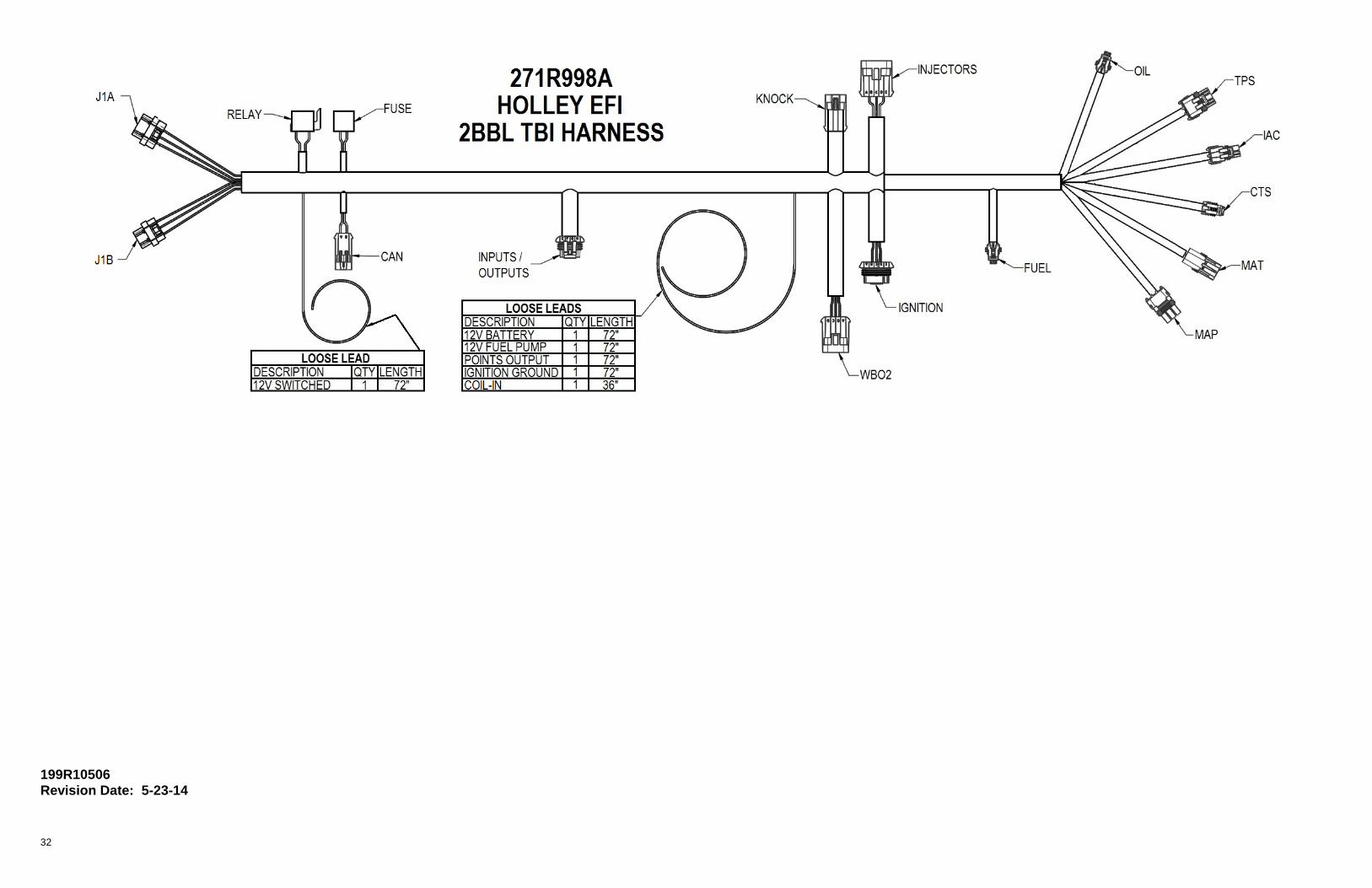
12.0 PRIMARY HARNESS INSTALLATION AND SENSORS CONNECTION These sections review the Main Harness installation and all of the sensor connections that must be completed. The Main Harness is the primary harness that supports all the primary engine sensors, fuel and ignition. There are two main connectors for this harness that plug into the ECU.
Figure 14
20
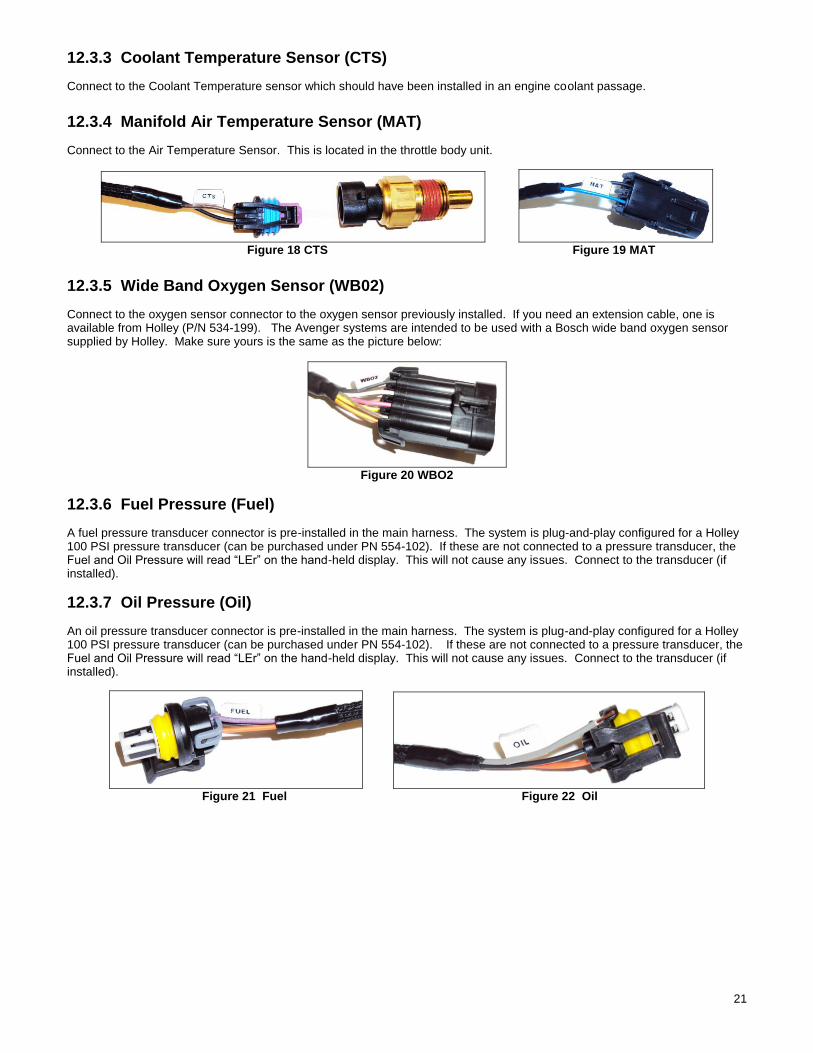
12.1 ECU Connectors
AVENGER ECU – The AVENGER ECU has two main connectors:
J1A - The first connector next to the USB connector is the “J1A” connector (34 pin). This connector is primarily an “Input” connector. It contains all the sensor inputs and wide band oxygen sensor control.
J1B - The second connector is the “J1B” connector (26 pin). This connector is the “output” connector. It has 8 injector outputs and outputs for other devices.
Figure 15
*USB is not used on Avenger EFI
12.2 Harness Routing If the ECU is mounted in the interior, it will have to be routed through the firewall into the engine compartment. Use a 2” hole saw to create a hole in a desired location if no other point of access is available. A grommet is supplied for a 2” hole to seal this area. If the ECU is mounted in the engine compartment, the hand-held tuning module cable will have to be routed to the “CAN” connector on the main harness (located near the ECU connector main connector). This will require routing 1” x ½” connector somewhere through the firewall. Connect the J1A and J1B connectors of the main harness into the ECU. About 12” from the ECU main connectors is a 40A Relay. This powers the injectors and fuel pump.
12.3 Sensor Connections & Outputs The following indicates the primary sensors that are required to be connected. Each connector on the main harness is labeled with the sensor name. The name on this label for each sensor is in parenthesis below.
12.3.1 Throttle Position Sensor (TPS)
Connect to the TPS which is located on the throttle body.
12.3.2 Manifold Air Pressure Sensor (MAP)
A 1 Bar MAP sensor is provided with all Holley EFI systems. Connect to the MAP sensor. Make sure that a vacuum line was connected to the MAP sensor in previous steps.
Figure 16 TPS Figure 17 MAP
21
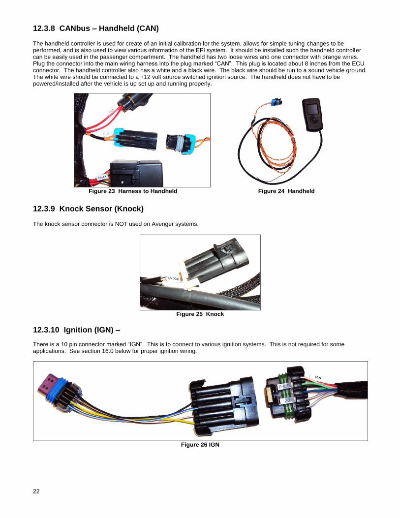
12.3.3 Coolant Temperature Sensor (CTS)
Connect to the Coolant Temperature sensor which should have been installed in an engine coolant passage.
12.3.4 Manifold Air Temperature Sensor (MAT)
Connect to the Air Temperature Sensor. This is located in the throttle body unit.
Figure 18 CTS Figure 19 MAT
12.3.5 Wide Band Oxygen Sensor (WB02)
Connect to the oxygen sensor connector to the oxygen sensor previously installed. If you need an extension cable, one is available from Holley (P/N 534-199). The Avenger systems are intended to be used with a Bosch wide band oxygen sensor supplied by Holley. Make sure yours is the same as the picture below:
Figure 20 WBO2
12.3.6 Fuel Pressure (Fuel)
A fuel pressure transducer connector is pre-installed in the main harness. The system is plug-and-play configured for a Holley 100 PSI pressure transducer (can be purchased under PN 554-102). If these are not connected to a pressure transducer, the Fuel and Oil Pressure will read “LEr” on the hand-held display. This will not cause any issues. Connect to the transducer (if installed).
12.3.7 Oil Pressure (Oil)
An oil pressure transducer connector is pre-installed in the main harness. The system is plug-and-play configured for a Holley 100 PSI pressure transducer (can be purchased under PN 554-102). If these are not connected to a pressure transducer, the Fuel and Oil Pressure will read “LEr” on the hand-held display. This will not cause any issues. Connect to the transducer (if installed).
Figure 21 Fuel Figure 22 Oil
22
12.3.8 CANbus – Handheld (CAN) The handheld controller is used for create of an initial calibration for the system, allows for simple tuning changes to be performed, and is also used to view various information of the EFI system. It should be installed such the handheld controller can be easily used in the passenger compartment. The handheld has two loose wires and one connector with orange wires. Plug the connector into the main wiring harness into the plug marked “CAN”. This plug is located about 8 inches from the ECU connector. The handheld controller also has a white and a black wire. The black wire should be run to a sound vehicle ground. The white wire should be connected to a +12 volt source switched ignition source. The handheld does not have to be powered/installed after the vehicle is up set up and running properly.
Figure 23 Harness to Handheld Figure 24 Handheld
12.3.9 Knock Sensor (Knock) The knock sensor connector is NOT used on Avenger systems.
Figure 25 Knock
12.3.10 Ignition (IGN) – There is a 10 pin connector marked “IGN”. This is to connect to various ignition systems. This is not required for some applications. See section 16.0 below for proper ignition wiring.
Figure 26 IGN
23
13.0 PRIMARY OUTPUTS
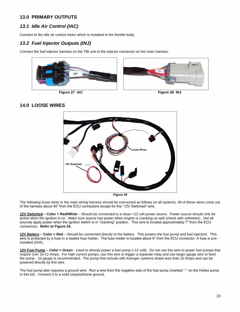
13.1 Idle Air Control (IAC)
Connect to the idle air control motor which is installed in the throttle body.
13.2 Fuel Injector Outputs (INJ)
Connect the fuel injector harness on the TBI unit to the injector connector on the main harness.
Figure 27 IAC Figure 28 INJ
14.0 LOOSE WIRES
Figure 29
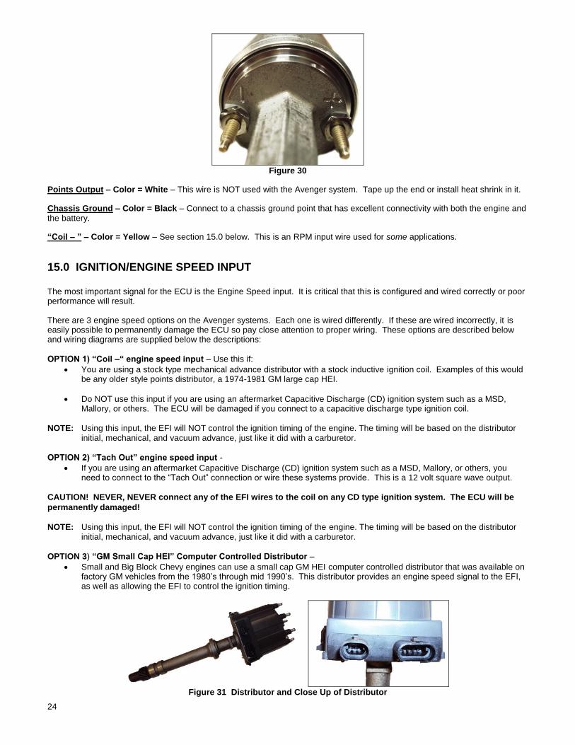
The following loose wires in the main wiring harness should be connected as follows on all systems. All of these wires come out of the harness about 40” from the ECU connectors except for the “12V Switched” wire.
12V Switched – Color = Red/White – Should be connected to a clean +12 volt power source. Power source should only be active when the ignition is on. Make sure source has power when engine is cranking as well (check with voltmeter). Not all sources apply power when the ignition switch is in “cranking” position. This wire is located approximately 7” from the ECU
connectors. Refer to Figure 24.
12V Battery – Color = Red – Should be connected directly to the battery. This powers the fuel pump and fuel injectors. This wire is protected by a fuse in a sealed fuse holder. The fuse holder is located about 9” from the ECU connector. A fuse is pre-installed (20A).
12V Fuel Pump – Color = Green - Used to directly power a fuel pump (+12 volt). Do not use this wire to power fuel pumps that require over 10-12 Amps. For high current pumps, use this wire to trigger a separate relay and use larger gauge wire to feed the pump - 10 gauge is recommended. The pump that include with Avenger systems draws less than 10 Amps and can be powered directly by this wire. The fuel pump also requires a ground wire. Run a wire from the negative side of the fuel pump (marked “-“ on the Holley pump in this kit). Connect it to a solid chassis/frame ground.
24
Figure 30
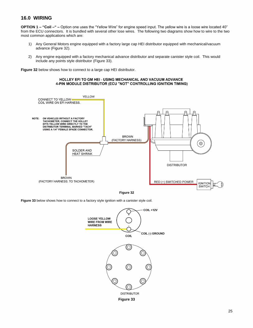
Points Output – Color = White – This wire is NOT used with the Avenger system. Tape up the end or install heat shrink in it.
Chassis Ground – Color = Black – Connect to a chassis ground point that has excellent connectivity with both the engine and the battery.
“Coil – ” – Color = Yellow – See section 15.0 below. This is an RPM input wire used for some applications.
15.0 IGNITION/ENGINE SPEED INPUT The most important signal for the ECU is the Engine Speed input. It is critical that this is configured and wired correctly or poor performance will result. There are 3 engine speed options on the Avenger systems. Each one is wired differently. If these are wired incorrectly, it is easily possible to permanently damage the ECU so pay close attention to proper wiring. These options are described below and wiring diagrams are supplied below the descriptions:
OPTION 1) “Coil –“ engine speed input – Use this if:
You are using a stock type mechanical advance distributor with a stock inductive ignition coil. Examples of this would be any older style points distributor, a 1974-1981 GM large cap HEI.
Do NOT use this input if you are using an aftermarket Capacitive Discharge (CD) ignition system such as a MSD, Mallory, or others. The ECU will be damaged if you connect to a capacitive discharge type ignition coil.
NOTE: Using this input, the EFI will NOT control the ignition timing of the engine. The timing will be based on the distributor initial, mechanical, and vacuum advance, just like it did with a carburetor.
OPTION 2) “Tach Out” engine speed input -
If you are using an aftermarket Capacitive Discharge (CD) ignition system such as a MSD, Mallory, or others, you need to connect to the “Tach Out” connection or wire these systems provide. This is a 12 volt square wave output.
CAUTION! NEVER, NEVER connect any of the EFI wires to the coil on any CD type ignition system. The ECU will be
permanently damaged!
NOTE: Using this input, the EFI will NOT control the ignition timing of the engine. The timing will be based on the distributor initial, mechanical, and vacuum advance, just like it did with a carburetor.
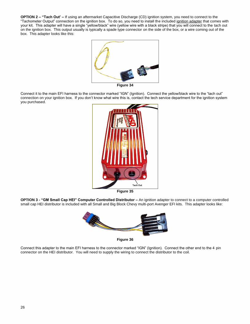
OPTION 3) “GM Small Cap HEI” Computer Controlled Distributor –
Small and Big Block Chevy engines can use a small cap GM HEI computer controlled distributor that was available on factory GM vehicles from the 1980’s through mid 1990’s. This distributor provides an engine speed signal to the EFI, as well as allowing the EFI to control the ignition timing.
Figure 31 Distributor and Close Up of Distributor
25
16.0 WIRING
OPTION 1 – “Coil –“ – Option one uses the “Yellow Wire” for engine speed input. The yellow wire is a loose wire located 40” from the ECU connectors. It is bundled with several other lose wires. The following two diagrams show how to wire to the two most common applications which are:
1) Any General Motors engine equipped with a factory large cap HEI distributor equipped with mechanical/vacuum advance (Figure 32).
2) Any engine equipped with a factory mechanical advance distributor and separate canister style coil. This would include any points style distributor (Figure 33).
Figure 32 below shows how to connect to a large cap HEI distributor.
Figure 32
Figure 33 below shows how to connect to a factory style ignition with a canister style coil.
Figure 33
26
OPTION 2 – “Tach Out’ – If using an aftermarket Capacitive Discharge (CD) ignition system, you need to connect to the “Tachometer Output” connection on the ignition box. To do so, you need to install the included ignition adapter that comes with your kit. This adapter will have a single “yellow/black” wire (yellow wire with a black stripe) that you will connect to the tach out on the ignition box. This output usually is typically a spade type connector on the side of the box, or a wire coming out of the box. This adapter looks like this:
Figure 34
Connect it to the main EFI harness to the connector marked “IGN” (Ignition). Connect the yellow/black wire to the “tach out” connection on your ignition box. If you don’t know what wire this is, contact the tech service department for the ignition system you purchased.
Figure 35
OPTION 3 - “GM Small Cap HEI” Computer Controlled Distributor – An ignition adapter to connect to a computer controlled small cap HEI distributor is included with all Small and Big Block Chevy multi-port Avenger EFI kits. This adapter looks like:
Figure 36
Connect this adapter to the main EFI harness to the connector marked “IGN” (Ignition). Connect the other end to the 4 pin connector on the HEI distributor. You will need to supply the wiring to connect the distributor to the coil.
27
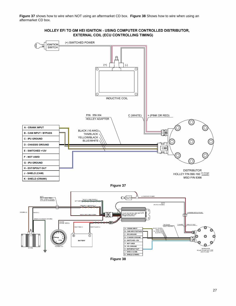
Figure 37 shows how to wire when NOT using an aftermarket CD box. Figure 38 Shows how to wire when using an aftermarket CD box.
Figure 37
Figure 38
28
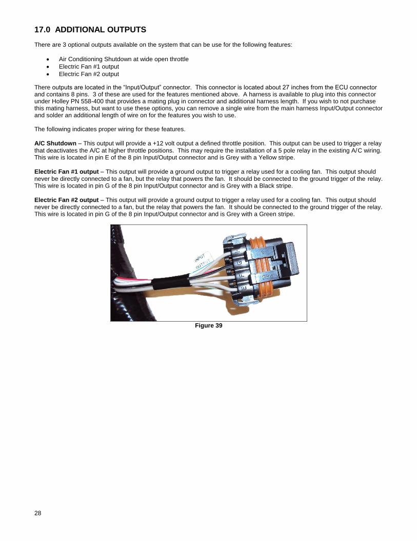
17.0 ADDITIONAL OUTPUTS There are 3 optional outputs available on the system that can be use for the following features:
Air Conditioning Shutdown at wide open throttle
Electric Fan #1 output
Electric Fan #2 output
There outputs are located in the “Input/Output” connector. This connector is located about 27 inches from the ECU connector and contains 8 pins. 3 of these are used for the features mentioned above. A harness is available to plug into this connector under Holley PN 558-400 that provides a mating plug in connector and additional harness length. If you wish to not purchase this mating harness, but want to use these options, you can remove a single wire from the main harness Input/Output connector and solder an additional length of wire on for the features you wish to use. The following indicates proper wiring for these features.
A/C Shutdown – This output will provide a +12 volt output a defined throttle position. This output can be used to trigger a relay that deactivates the A/C at higher throttle positions. This may require the installation of a 5 pole relay in the existing A/C wiring. This wire is located in pin E of the 8 pin Input/Output connector and is Grey with a Yellow stripe.
Electric Fan #1 output – This output will provide a ground output to trigger a relay used for a cooling fan. This output should never be directly connected to a fan, but the relay that powers the fan. It should be connected to the ground trigger of the relay. This wire is located in pin G of the 8 pin Input/Output connector and is Grey with a Black stripe.
Electric Fan #2 output – This output will provide a ground output to trigger a relay used for a cooling fan. This output should never be directly connected to a fan, but the relay that powers the fan. It should be connected to the ground trigger of the relay. This wire is located in pin G of the 8 pin Input/Output connector and is Grey with a Green stripe.
Figure 39
29
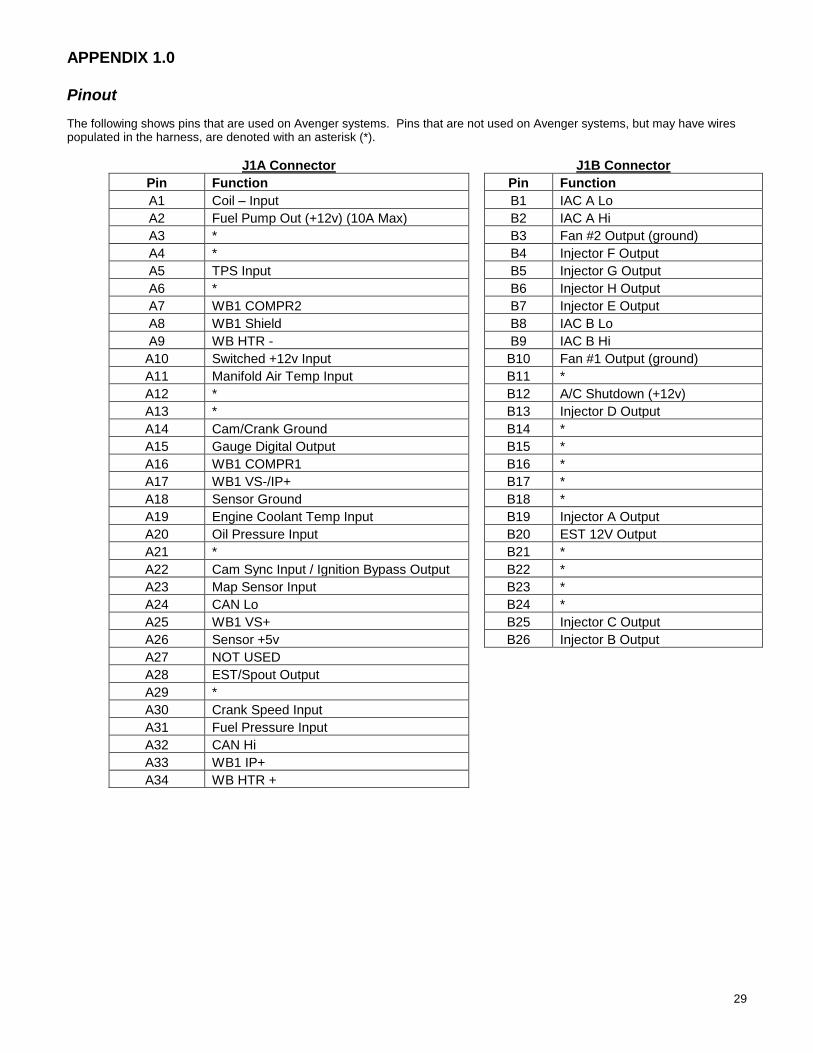
APPENDIX 1.0 Pinout
The following shows pins that are used on Avenger systems. Pins that are not used on Avenger systems, but may have wires populated in the harness, are denoted with an asterisk (*).
J1A Connector J1B Connector
Pin Function Pin Function
A1 Coil – Input B1 IAC A Lo
A2 Fuel Pump Out (+12v) (10A Max) B2 IAC A Hi
A3 * B3 Fan #2 Output (ground)
A4 * B4 Injector F Output
A5 TPS Input B5 Injector G Output
A6 * B6 Injector H Output
A7 WB1 COMPR2 B7 Injector E Output
A8 WB1 Shield B8 IAC B Lo
A9 WB HTR - B9 IAC B Hi
A10 Switched +12v Input B10 Fan #1 Output (ground)
A11 Manifold Air Temp Input B11 *
A12 * B12 A/C Shutdown (+12v)
A13 * B13 Injector D Output
A14 Cam/Crank Ground B14 *
A15 Gauge Digital Output B15 *
A16 WB1 COMPR1 B16 *
A17 WB1 VS-/IP+ B17 *
A18 Sensor Ground B18 *
A19 Engine Coolant Temp Input B19 Injector A Output
A20 Oil Pressure Input B20 EST 12V Output
A21 * B21 *
A22 Cam Sync Input / Ignition Bypass Output B22 *
A23 Map Sensor Input B23 *
A24 CAN Lo B24 *
A25 WB1 VS+ B25 Injector C Output
A26 Sensor +5v B26 Injector B Output
A27 NOT USED
A28 EST/Spout Output
A29 *
A30 Crank Speed Input
A31 Fuel Pressure Input
A32 CAN Hi
A33 WB1 IP+
A34 WB HTR +

30
Holley Technical Support
1801 Russellville Road
Bowling Green, KY 42101
Phone: 1-270-781-9741
Fax: 1-270-781-9772
For online help, please refer to the Tech
Service section of our website:
www.holley.com
199R10506 wf Revision Date: 5-15-14
31
32
199R10506
Revision Date: 5-23-14