Embed Size (px)
Citation preview
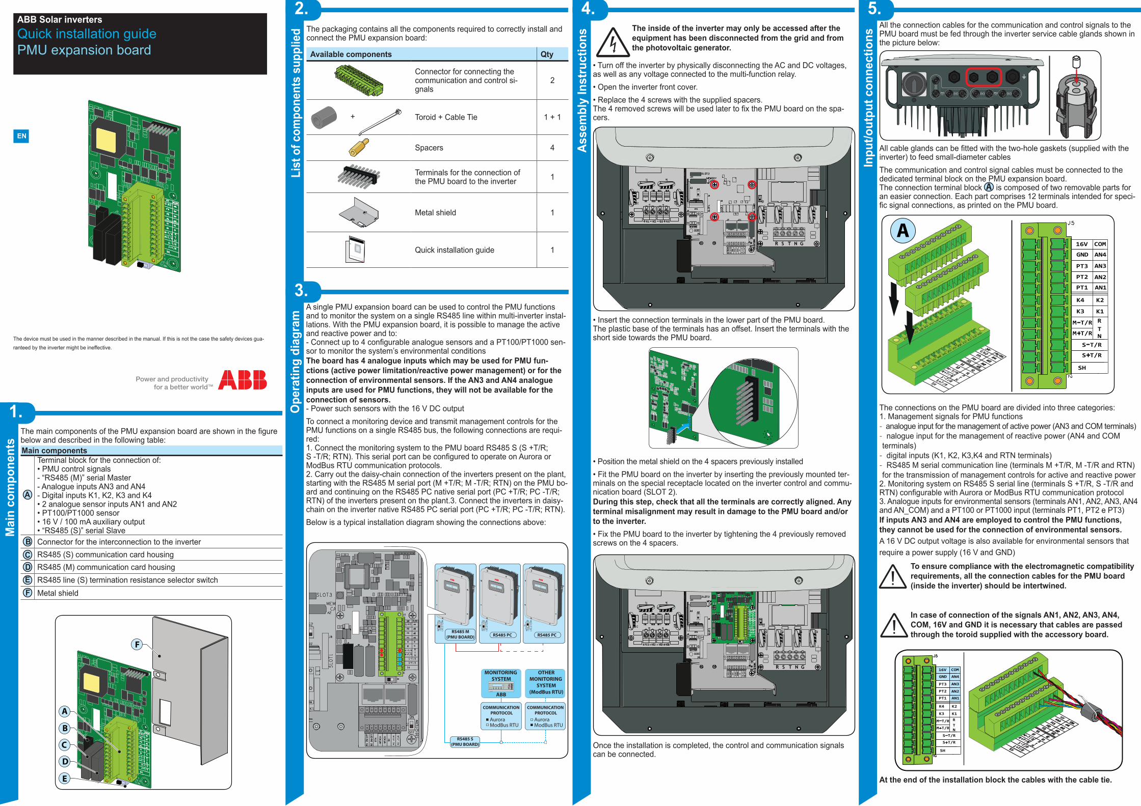
ABB Solar invertersQuick installation guidePMU expansion board
EN
The device must be used in the manner described in the manual. If this is not the case the safety devices gua-ranteed by the inverter might be ineffective.
1.
2.
3.
4. 5.
Asse
mbl
y In
stru
ctio
ns
Inpu
t/out
put c
onne
ctio
ns
Mai
n co
mpo
nent
s
List
of c
ompo
nent
s su
pplie
dO
pera
ting
diag
ram
The main components of the PMU expansion board are shown in the figure below and described in the following table:Main components
A
Terminal block for the connection of:• PMU control signals- “RS485 (M)” serial Master- Analogue inputs AN3 and AN4- Digital inputs K1, K2, K3 and K4• 2 analogue sensor inputs AN1 and AN2• PT100/PT1000 sensor• 16 V / 100 mA auxiliary output• “RS485 (S)” serial Slave
B Connector for the interconnection to the inverterC RS485 (S) communication card housingD RS485 (M) communication card housingE RS485 line (S) termination resistance selector switchF Metal shield
All the connection cables for the communication and control signals to the PMU board must be fed through the inverter service cable glands shown in the picture below:
All cable glands can be fitted with the two-hole gaskets (supplied with the inverter) to feed small-diameter cablesThe communication and control signal cables must be connected to the dedicated terminal block on the PMU expansion board. The connection terminal block A is composed of two removable parts for an easier connection. Each part comprises 12 terminals intended for speci-fic signal connections, as printed on the PMU board.
K3 K1RM T/R
M T/RTN
S T/R
S T/R
SH
PT1
K4 K2
AN1
16V COM
PT3
GND AN4
AN3
PT2 AN2
A
The connections on the PMU board are divided into three categories:1. Management signals for PMU functions - analogue input for the management of active power (AN3 and COM terminals) - nalogue input for the management of reactive power (AN4 and COM terminals) - digital inputs (K1, K2, K3,K4 and RTN terminals) - RS485 M serial communication line (terminals M +T/R, M -T/R and RTN) for the transmission of management controls for active and reactive power
2. Monitoring system on RS485 S serial line (terminals S +T/R, S -T/R and RTN) configurable with Aurora or ModBus RTU communication protocol3. Analogue inputs for environmental sensors (terminals AN1, AN2, AN3, AN4 and AN_COM) and a PT100 or PT1000 input (terminals PT1, PT2 e PT3)If inputs AN3 and AN4 are employed to control the PMU functions, they cannot be used for the connection of environmental sensors. A 16 V DC output voltage is also available for environmental sensors that require a power supply (16 V and GND)
To ensure compliance with the electromagnetic compatibility requirements, all the connection cables for the PMU board (inside the inverter) should be intertwined.
In case of connection of the signals AN1, AN2, AN3, AN4, COM, 16V and GND it is necessary that cables are passed through the toroid supplied with the accessory board.
16VK3 K1
RM T/R
M T/RTN
S T/R
S T/R
SH
PT1
K4 K2
AN1
16V COM
PT3
GND AN4
AN3
PT2 AN2
At the end of the installation block the cables with the cable tie.
A single PMU expansion board can be used to control the PMU functions and to monitor the system on a single RS485 line within multi-inverter instal-lations. With the PMU expansion board, it is possible to manage the active and reactive power and to:- Connect up to 4 configurable analogue sensors and a PT100/PT1000 sen-sor to monitor the system’s environmental conditionsThe board has 4 analogue inputs which may be used for PMU fun-ctions (active power limitation/reactive power management) or for the connection of environmental sensors. If the AN3 and AN4 analogue inputs are used for PMU functions, they will not be available for the connection of sensors.- Power such sensors with the 16 V DC outputTo connect a monitoring device and transmit management controls for the PMU functions on a single RS485 bus, the following connections are requi-red:1. Connect the monitoring system to the PMU board RS485 S (S +T/R; S -T/R; RTN). This serial port can be configured to operate on Aurora or ModBus RTU communication protocols.2. Carry out the daisy-chain connection of the inverters present on the plant, starting with the RS485 M serial port (M +T/R; M -T/R; RTN) on the PMU bo-ard and continuing on the RS485 PC native serial port (PC +T/R; PC -T/R; RTN) of the inverters present on the plant.3. Connect the inverters in daisy-chain on the inverter native RS485 PC serial port (PC +T/R; PC -T/R; RTN).Below is a typical installation diagram showing the connections above:
RS485 PCRS485 M
(PMU BOARD) RS485 PC
Aurora
COMMUNICATION PROTOCOL
ModBus RTUAuroraModBus RTU
MONITORING SYSTEM
ABB
OTHERMONITORING
SYSTEM(ModBus RTU)
COMMUNICATION PROTOCOL
RS485 S(PMU BOARD)
PVI-AEC-EVO
Power ON
Bus ON
Fault
A
B
SD C
ard
V DC: 18-48 VIN
Ta(°C): -20 to +55
TRIO
POWER ALARM GFI ESC UP DOWN ENTER
TRIO
POWER ALARM GFI ESC UP DOWN ENTER
TRIO
POWER ALARM GFI ESC UP DOWN ENTER
1
J3 J2
J5
S4
J6
16V
The inside of the inverter may only be accessed after the equipment has been disconnected from the grid and from the photovoltaic generator.
• Turn off the inverter by physically disconnecting the AC and DC voltages, as well as any voltage connected to the multi-function relay.• Open the inverter front cover. • Replace the 4 screws with the supplied spacers. The 4 removed screws will be used later to fix the PMU board on the spa-cers.
1
R S T N G
• Insert the connection terminals in the lower part of the PMU board.The plastic base of the terminals has an offset. Insert the terminals with the short side towards the PMU board.
• Position the metal shield on the 4 spacers previously installed• Fit the PMU board on the inverter by inserting the previously mounted ter-minals on the special receptacle located on the inverter control and commu-nication board (SLOT 2).During this step, check that all the terminals are correctly aligned. Any terminal misalignment may result in damage to the PMU board and/or to the inverter.• Fix the PMU board to the inverter by tightening the 4 previously removed screws on the 4 spacers.
1
R S T N G
J3 J2
J5
S4
J6
Once the installation is completed, the control and communication signals can be connected.
LAB
1
J6
16
15
2
1
The packaging contains all the components required to correctly install and connect the PMU expansion board:
Available components Qty
Connector for connecting the communication and control si-gnals
2
+ Toroid + Cable Tie 1 + 1
Spacers 4
Terminals for the connection of the PMU board to the inverter 1
Metal shield 1
In addition to what is explained in this guide, the safety and installation information provided in the installation manual must be read and followed.
The technical documentation and the interface and management software for the product are available at the website.
XXXXXXXXXXXXXXXXXXX
XXXXXXXXXXXXXXXXXXX
ABB solar inverters
Quick installation guide 1
LAB
1
J6
16
15
2
1
B
F
A
C
D
E

Contact uswww.abb.com/solarinverters
PMU expansion board-Quick Installation Guide EN-RevCEFFECTIVE 2014-02-12
© Copyright 2014 ABB. All Rights Reserved.Specifications subject to change without notice.
8.
Char
acte
ristic
s an
d te
chni
cal d
ata
7.
PMU
oper
atio
n
PMU
oper
atio
n The PMU board runs the active power limitation and reactive power mana-gement functions in different operation modes. Each mode allows to mana-ge and “translate” the digital input states and the analogue input levels into corresponding controls, which are then transmitted via the RS485 M serial port to one or more inverters connected to the RS485 bus, without interfe-ring with the operation of any monitoring device that may be connected to the same bus. The PMU controls are effectively transmitted as broadcast commands, with the PMU interrupting for a few milliseconds the commu-nication line used for monitoring in order to send the PMU function control signals.
• The active power control is defined (based on the chosen operation mode) either by the state of the digital inputs or by the level of analogue input AN3.• The active and reactive power management controls transmitted to the inverters connected to the RS485 M line define:- Set point: set point for the active and reactive power- Smooth time: the time the inverter requires to reach the new (active and/or reactive) power set point - Timeout: the time during which the inverter holds the set point (60 sec.)
The table below illustrates the active power limitation / reactive power mana-gement modes that can be selected on the inverter display:Display-ed name Operation Inputs
Mode 0 No PMU function selected -Mode 1 4-step active power reduction K1, K2, K3, K4Mode 2 Active power reduction via analogue inputs AN3
Mode 3 4-step active power reduction K1, K2, K3, K4Reactive power control via analogue inputs AN4 (Type 2)
Mode 4 Active power reduction via analogue inputs AN3Reactive power control via analogue inputs AN4 (Type 2)
Mode 5 4-step active power reduction K1, K2, K3, K4Reactive power control via analogue inputs AN4 (Type 4)
Mode 6 Active power reduction via analogue inputs AN3Reactive power control via analogue inputs AN4 (Type 4)
Mode 7 Reactive power control via analogue inputs AN4 (Type 2)Mode 8 Reactive power control via analogue inputs AN4 (Type 4)
Mode 9 11-step active power reduction K1, K2, K3, K4Reactive power control via analogue inputs AN4 (Type 4)
Mode 10 Active power reduction via analogue inputs AN3 Reactive power control via analogue inputs AN4 (Type 4)
- 4-step active power control via digital inputs This control type is used in operation modes 1, 3, 5.The digital inputs used for the active power limitation function are K1, K2, K3 and K4
K1 K2 K3 K4 Maximum active power as % of the inverter nominal power
Closed Open Open Open 100Open Closed Open Open 60Open Open Closed Open 30Open Open Open Closed 0
- 11-step active power control via digital inputs.This control type is used in operation mode 9.The digital inputs used for the active power limitation function are K1, K2, K3 and K4
K1 K2 K3 K4 Maximum active power as % of the inverter nominal power
Open Closed Open Closed 100Closed Open Open Closed 90Open Open Open Closed 80Closed Closed Closed Open 70Open Closed Closed Open 60Closed Open Closed Open 50Open Open Closed Open 40Closed Closed Open Open 30Open Closed Open Open 20Closed Open Open Open 15Closed Closed Open Closed 0
- Active power control via analogue input (AN3).This control type is used in operation modes 2, 4, 6, 10.The analogue input used for the active power limitation function is AN3.This control dynamically manages the output active power based on the level of the input analogue signal. This can be either a current (4...20 mA) or a vol-tage (0...10 V) signal.The inverter nominal output power limitation is applied as shown in the cha-racteristics below (left → current input; right → voltage input):
Input current AN3 (mA)
Nom
inal
Pou
t (%
)
Nom
inal
Pou
t (%
)
0
10
20
30
40
50
60
70
80
90
100
4 6 8 10 12 14 16 18 20
Input Voltage AN3 (V)
0
10
20
30
40
50
60
70
80
90
100
0 2 4 6 8 10
- Reactive power control via analogue input (AN4).This control type is used in operation modes 3, 4, 5, 6, 7, 8, 9 and 10. The management modes follow different behaviours, as described below.The analogue input for the reactive power control function is AN4.This control dynamically manages the reactive power based on the level of the input analogue signal. This can be either a current (4...20 mA) or a volta-ge (0...10 V) signal.2 reactive power management modes are available:Type 2 → Fixed tan(ϕ), based on the instantaneous output powerType 4 → Fixed cos(ϕ), based on the instantaneous output power
The inverter reactive power management is applied as shown in the cha-racteristics below (left → current input; right → voltage input):
Operation Type 2
Input current AN4 (mA)
4 6 8 10 12 14 16 18 20
0.050.00
0.10
0.15
0.20
0.25
0.30
0.35
0.40
0.45
0.50
0.55
0.050.00
0.10
0.15
0.20
0.25
0.30
0.35
0.40
0.45
0.50
0.55
Input Voltage AN4 (V)
TanΦTanΦ
0 21 3 4 5 6 7 8 9 10
Capacitive reactive power
TanΦ<0
Inductive reactive power
TanΦ>0
Capacitive reactive power
TanΦ<0
Inductive reactive power
TanΦ>0
Operation Type 4
Input current AN4 (mA)
4 6 8 10 12 14 16 18 20
0.900.89
0.91
0.92
0.93
0.94
0.95
0.96
0.97
0.98
0.99
1.00
Input Voltage AN4 (V)
CosΦCosΦ
0 21 3 4 5 6 7 8 9 10
0.900.89
0.91
0.92
0.93
0.94
0.95
0.96
0.97
0.98
0.99
1.00Capacitive
reactive power
CosΦ<0
Inductive reactive power
CosΦ>0
Capacitive reactive power
CosΦ<0
Inductive reactive power
CosΦ>0
6.O
n-di
spla
y co
nfigu
ratio
n Upon starting the inverter for the first time after the PMU board has been installed, a new “PMU Board” section is added to the SETTINGS menu, with the following tree:
PMU Board
RS485 Slave
Address RS485
Protocol
Aurora (Slave)Mod Bus RTUAurora (Bridge)
No selectIRRIRR-T...Manual
24004800...
I/VGainOffsetUnit
Baud Rate
Mode 0Mode 1 Mode 2...
PMU Mode
Analog Input
AN1
AN2
AN3
AN4
PT100/PT1000
*1
*2
*4
*3
• “RS485 Slave” section - View of the RS485 address for the RS485 S line (if more than one PMU board is installed) - Sets the communication protocol (Aurora or ModBus RTU) - *1 Sets the communication line baud rate, configurable only if the “ModBus RTU” protocol is selected
• “PMU Mode” sectionSets the PMU to the desired operation mode The table in the following section shows the modes
• “Analogue Input” sectionAssigns each analogue input (AN1, AN2, AN3 and AN4) to the relevant environmental sensor connected, choosing from a list of ABB sensors.In case the connected sensor does not appear in the list, the configuration parameters (sensor type: voltage/current; gain; offset; measurement unit) can be set manually (“Manual”).
It also allows setting the input to PT100 or PT1000 mode, based on the type of the connected sensor
*2,*3 If AN3 and AN4 analogue inputs are used to control PMU fun-ctions, you can set the type of input (current or voltage)
*4 Settings available by selecting “Manual” from the list of available sensors
RS485 M - Master serial port (PMU)
Communication protocol Aurora
Serial interface RS485 Half-duplex
Baud Rate 19200 bps
Maximum number of inverters on the 485 bus 32
Maximum line length 1 km with shielded cable
RS485 S - Slave serial port(Monitoring)
Communication protocol Configurable:Aurora or ModBus RTU
Serial interface RS485 Half-duplex
Baud Rate (Aurora protocol) 19200 bps
Baud Rate (ModBus RTU protocol)Configurable from 2400 to
115200Default: 19200 bps
Maximum number of inverters on the 485 bus 32
Maximum line length 1 km with shielded cable
Analogue inputs
Number of inputs4 configurable analogue inputs(1) and 1 PT100/PT1000 input
Input type Configurable: current or voltage
Input current range 4...20mA
Input voltage range 0...10Vdc
16 V DC output
Output voltage 16Vdc
Output current 150mA
Digital inputs
Number of inputs 4
Input activation Contact active whenshorted to ground (RTN)
Nominal voltage 15Vdc
Output current 50mA
1. If analogue inputs AN3 and AN4 are used to control the PMU, the num-ber of analogue inputs available for the connection of environmental sen-sors is reduced to 2 (AN1 and AN2)


![An3 Analiza Econ Financ Probleme[1]](https://img.pdfslide.us/doc/110x75/5571f26449795947648c8744/an3-analiza-econ-financ-probleme1.jpg)