Embed Size (px)
Citation preview
Phone: (949) 679-5712 Fax: (949) 420-2134
17901 Von Karman Avenue, Suite 600, Irvine, CA 92614, USA
Email: [email protected]
© 2015 Optix Communications, Inc.
http://www.OptixCom.com
http://www.OpticalTransceiver.com
Page 1
10/2014
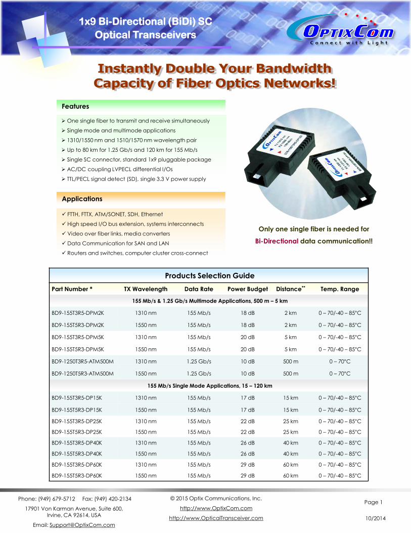
Products Selection Guide
Part Number * TX Wavelength Data Rate Power Budget Distance** Temp. Range
155 Mb/s & 1.25 Gb/s Multimode Applications, 500 m – 5 km
BD9-155T3R5-DPM2K 1310 nm 155 Mb/s 18 dB 2 km 0 – 70/-40 – 85°C
BD9-155T5R3-DPM2K 1550 nm 155 Mb/s 18 dB 2 km 0 – 70/-40 – 85°C
BD9-155T3R5-DPM5K 1310 nm 155 Mb/s 20 dB 5 km 0 – 70/-40 – 85°C
BD9-155T5R3-DPM5K 1550 nm 155 Mb/s 20 dB 5 km 0 – 70/-40 – 85°C
BD9-1250T3R5-ATM500M 1310 nm 1.25 Gb/s 10 dB 500 m 0 – 70°C
BD9-1250T5R3-ATM500M 1550 nm 1.25 Gb/s 10 dB 500 m 0 – 70°C
155 Mb/s Single Mode Applications, 15 – 120 km
BD9-155T3R5-DP15K 1310 nm 155 Mb/s 17 dB 15 km 0 – 70/-40 – 85°C
BD9-155T5R3-DP15K 1550 nm 155 Mb/s 17 dB 15 km 0 – 70/-40 – 85°C
BD9-155T3R5-DP25K 1310 nm 155 Mb/s 22 dB 25 km 0 – 70/-40 – 85°C
BD9-155T5R3-DP25K 1550 nm 155 Mb/s 22 dB 25 km 0 – 70/-40 – 85°C
BD9-155T3R5-DP40K 1310 nm 155 Mb/s 26 dB 40 km 0 – 70/-40 – 85°C
BD9-155T5R3-DP40K 1550 nm 155 Mb/s 26 dB 40 km 0 – 70/-40 – 85°C
BD9-155T3R5-DP60K 1310 nm 155 Mb/s 29 dB 60 km 0 – 70/-40 – 85°C
BD9-155T5R3-DP60K 1550 nm 155 Mb/s 29 dB 60 km 0 – 70/-40 – 85°C
One single fiber to transmit and receive simultaneously
Single mode and multimode applications
1310/1550 nm and 1510/1570 nm wavelength pair
Up to 80 km for 1.25 Gb/s and 120 km for 155 Mb/s
Single SC connector, standard 1x9 pluggable package
AC/DC coupling LVPECL differential I/Os
TTL/PECL signal detect (SD), single 3.3 V power supply
FTTH, FTTX, ATM/SONET, SDH, Ethernet
High speed I/O bus extension, systems interconnects
Video over fiber links, media converters
Data Communication for SAN and LAN
Routers and switches, computer cluster cross-connect
Only one single fiber is needed for
Bi-Directional data communication!!
Features
Applications
1x9 Bi-Directional (BiDi) SC
Optical Transceivers
Phone: (949) 679-5712 Fax: (949) 420-2134
17901 Von Karman Avenue, Suite 600, Irvine, CA 92614, USA
Email: [email protected]
© 2015 Optix Communications, Inc.
http://www.OptixCom.com
http://www.OpticalTransceiver.com
Page 2
10/2014
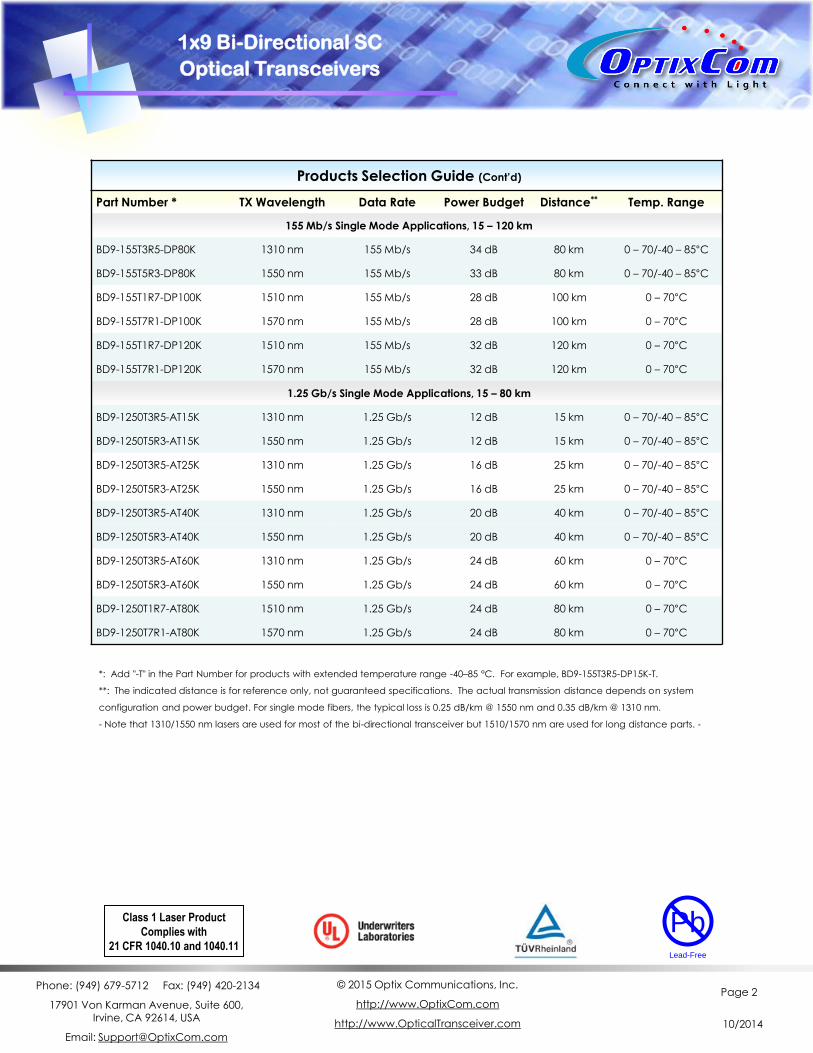
*: Add "-T" in the Part Number for products with extended temperature range -40–85 °C. For example, BD9-155T3R5-DP15K-T.
**: The indicated distance is for reference only, not guaranteed specifications. The actual transmission distance depends on system
configuration and power budget. For single mode fibers, the typical loss is 0.25 dB/km @ 1550 nm and 0.35 dB/km @ 1310 nm.
- Note that 1310/1550 nm lasers are used for most of the bi-directional transceiver but 1510/1570 nm are used for long distance parts. -
Products Selection Guide (Cont’d)
Part Number * TX Wavelength Data Rate Power Budget Distance** Temp. Range
155 Mb/s Single Mode Applications, 15 – 120 km
BD9-155T3R5-DP80K 1310 nm 155 Mb/s 34 dB 80 km 0 – 70/-40 – 85°C
BD9-155T5R3-DP80K 1550 nm 155 Mb/s 33 dB 80 km 0 – 70/-40 – 85°C
BD9-155T1R7-DP100K 1510 nm 155 Mb/s 28 dB 100 km 0 – 70°C
BD9-155T7R1-DP100K 1570 nm 155 Mb/s 28 dB 100 km 0 – 70°C
BD9-155T1R7-DP120K 1510 nm 155 Mb/s 32 dB 120 km 0 – 70°C
BD9-155T7R1-DP120K 1570 nm 155 Mb/s 32 dB 120 km 0 – 70°C
1.25 Gb/s Single Mode Applications, 15 – 80 km
BD9-1250T3R5-AT15K 1310 nm 1.25 Gb/s 12 dB 15 km 0 – 70/-40 – 85°C
BD9-1250T5R3-AT15K 1550 nm 1.25 Gb/s 12 dB 15 km 0 – 70/-40 – 85°C
BD9-1250T3R5-AT25K 1310 nm 1.25 Gb/s 16 dB 25 km 0 – 70/-40 – 85°C
BD9-1250T5R3-AT25K 1550 nm 1.25 Gb/s 16 dB 25 km 0 – 70/-40 – 85°C
BD9-1250T3R5-AT40K 1310 nm 1.25 Gb/s 20 dB 40 km 0 – 70/-40 – 85°C
BD9-1250T5R3-AT40K 1550 nm 1.25 Gb/s 20 dB 40 km 0 – 70/-40 – 85°C
BD9-1250T3R5-AT60K 1310 nm 1.25 Gb/s 24 dB 60 km 0 – 70°C
BD9-1250T5R3-AT60K 1550 nm 1.25 Gb/s 24 dB 60 km 0 – 70°C
BD9-1250T1R7-AT80K 1510 nm 1.25 Gb/s 24 dB 80 km 0 – 70°C
BD9-1250T7R1-AT80K 1570 nm 1.25 Gb/s 24 dB 80 km 0 – 70°C
Class 1 Laser Product
Complies with
21 CFR 1040.10 and 1040.11
Pb
Lead-Free
1x9 Bi-Directional SC
Optical Transceivers

Phone: (949) 679-5712 Fax: (949) 420-2134
17901 Von Karman Avenue, Suite 600, Irvine, CA 92614, USA
Email: [email protected]
© 2015 Optix Communications, Inc.
http://www.OptixCom.com
http://www.OpticalTransceiver.com
Page 3
10/2014
1x9 Bi-Directional (BiDi) Transceivers
Description
The bi-directional (BIDI) transceiver product is unique in
that only one single fiber (single mode or multimode) is
required to transmit and receive signals simultaneously.
That means the total bandwidth capacity of an existing
cable infrastructure can be doubled instantly. The
typical design of a BIDI transceiver uses a 1310 nm LD to
transmit and 1550 nm PD to receive, and vice versa for
the matching one (1310 nm to receive and 1550 nm to
transmit) at the other end to make a complete link.
OptixCom’s BIDI transceivers utilize advanced filter
optics to separate the two wavelength with more than
45 dB of isolation. The products use industry standard
1x9 pluggable package. These transceivers operate at
155 Mb/s for 2 - 5 km transmission distance with
multimode fibers. The products are RoHS compliant.
Key Features
Applications
FTTH, Ethernet, ATM/SONET , SDH STM-1
High speed I/O for file server
Video over fiber links
Media converter, bus extension
Central offices routers and switches
Mass storage systems interconnect
Computer cluster cross-connect
Multimode, 155 M/s data rate
TX 1310/RX 1550 and TX 1550/RX1310 matching pair
2 – 5 km reach and single 3.3 V power supply
18 – 20 dB power budget
Industry standard 1x9 pluggable package
Single SC connector optical interface
DC coupling LVPECL differential I/O logics
LVPECL Signal detect to monitor optical signals
-40 – 85 °C extended temperatures available
RoHS compliant
BD9-155T3R5-DPMXK BD9-155T5R3-DPMXK
(X = 2, 5)
Ordering Information
Part Number: BD9-155T3R5-DPMXK
Description:
155 Mb/s, Multimode, 1x9 BIDI Transceiver, TX 1310
nm and RX 1550 nm, X km reach, 0 – 70 °C.
Part Number: BD9-155T5R3-DPMXK
Description:
155 Mb/s, Multimode, 1x9 BIDI Transceiver, TX 1550
nm and RX 1310 nm, X km reach, 0 – 70 °C.
* Add "-T" in the Part Number for extended temperature
range -40 – 85 °C, i.e., BD9-155T3R5-DPM5K-T.
Operating Conditions
Parameter Min. Typical Max. Units
Operate Temperature 0 25 70 °C
- T Transceivers -40 25 85 °C
Data Rate --- 155 200 Mb/s
Supply Voltage 3.1 3.3 3.5 V
155 Mb/s, 1x9 SC Package, BIDI
TX1310/RX1550, TX1550/RX1310 nm
Multimode, 2 – 5 km Distance
155 Mb/s, 223-1 NRZ Data Eye Pattern
TX RX
Pb
Lead-Free
Phone: (949) 679-5712 Fax: (949) 420-2134
17901 Von Karman Avenue, Suite 600, Irvine, CA 92614, USA
Email: [email protected]
© 2015 Optix Communications, Inc.
http://www.OptixCom.com
http://www.OpticalTransceiver.com
Page 4
10/2014
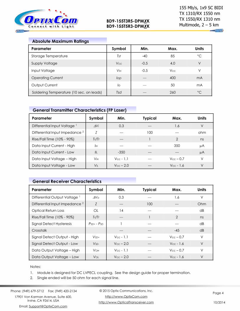
Absolute Maximum Ratings
Parameter Symbol Min. Max. Units
Storage Temperature Tst -40 85 °C
Supply Voltage Vcc -0.5 4.0 V
Input Voltage VIN -0.5 Vcc V
Operating Current Iop --- 400 mA
Output Current Io --- 50 mA
Soldering Temperature (10 sec. on leads) Tsd --- 260 °C
General Transmitter Characteristics (FP Laser)
Parameter Symbol Min. Typical Max. Units
Differential Input Voltage 1 DVi 0.3 --- 1.6 V
Differential Input Impedance 2 Z --- 100 --- ohm
Rise/Fall Time (10% - 90%) Tr/Tf --- 1 2 ns
Data Input Current - High IIH --- --- 350 mA
Data Input Current - Low IIL -350 --- --- mA
Data Input Voltage – High VIH Vcc - 1.1 --- Vcc – 0.7 V
Data Input Voltage - Low VIL Vcc – 2.0 --- Vcc - 1.6 V
Notes:
1. Module is designed for DC LVPECL coupling. See the design guide for proper termination.
2. Single ended will be 50 ohm for each signal line.
155 Mb/s, 1x9 SC BIDI
TX 1310/RX 1550 nm
TX 1550/RX 1310 nm
Multimode, 2 – 5 km BD9-155T3R5-DPMXK BD9-155T5R3-DPMXK
General Receiver Characteristics
Parameter Symbol Min. Typical Max. Units
Differential Output Voltage 1 DVo 0.3 --- 1.6 V
Differential Input Impedance 2 Z --- 100 --- Ohm
Optical Return Loss OL 14 --- --- dB
Rise/Fall Time (10% - 90%) Tr/Tf --- 1 2 ns
Signal Detect Hysteresis PSD+ - PSD 1 --- --- dB
Crosstalk --- --- -45 dB
Signal Detect Output - High VSD+ Vcc - 1.1 --- Vcc – 0.7 V
Signal Detect Output - Low VSD- Vcc – 2.0 --- Vcc - 1.6 V
Data Output Voltage – High VOH Vcc - 1.1 --- Vcc – 0.7 V
Data Output Voltage – Low VOL Vcc – 2.0 --- Vcc - 1.6 V
Phone: (949) 679-5712 Fax: (949) 420-2134
17901 Von Karman Avenue, Suite 600, Irvine, CA 92614, USA
Email: [email protected]
© 2015 Optix Communications, Inc.
http://www.OptixCom.com
http://www.OpticalTransceiver.com
Page 5
10/2014
155 Mb/s, 1x9 SC BIDI
TX 1310/RX 1550 nm
TX 1550/RX 1310 nm
Multimode, 2 km, 18 dB BD9-155T3R5-DPM2K BD9-155T5R3-DPM2K
--------------------------- BD9-155T3R5-DPM2K-T BD9-155T5R3-DPM2K-T
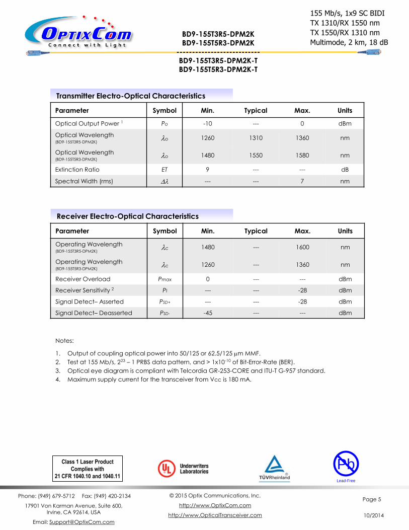
Transmitter Electro-Optical Characteristics
Parameter Symbol Min. Typical Max. Units
Optical Output Power 1 Po -10 --- 0 dBm
Optical Wavelength (BD9-155T3R5-DPM2K)
lo 1260 1310 1360 nm
Optical Wavelength (BD9-155T5R3-DPM2K)
lo 1480 1550 1580 nm
Extinction Ratio ET 9 --- --- dB
Spectral Width (rms) Dl --- --- 7 nm
Receiver Electro-Optical Characteristics
Parameter Symbol Min. Typical Max. Units
Operating Wavelength (BD9-155T3R5-DPM2K)
lc 1480 --- 1600 nm
Operating Wavelength (BD9-155T5R3-DPM2K)
lc 1260 --- 1360 nm
Receiver Overload Pmax 0 --- --- dBm
Receiver Sensitivity 2 PI --- --- -28 dBm
Signal Detect– Asserted PSD+ --- --- -28 dBm
Signal Detect– Deasserted PSD- -45 --- --- dBm
Notes:
1. Output of coupling optical power into 50/125 or 62.5/125 mm MMF.
2. Test at 155 Mb/s, 223 – 1 PRBS data pattern, and > 1x10⁻¹⁰ of Bit-Error-Rate (BER).
3. Optical eye diagram is compliant with Telcordia GR-253-CORE and ITU-T G-957 standard.
4. Maximum supply current for the transceiver from Vcc is 180 mA.
Class 1 Laser Product
Complies with
21 CFR 1040.10 and 1040.11
Pb
Lead-Free
Phone: (949) 679-5712 Fax: (949) 420-2134
17901 Von Karman Avenue, Suite 600, Irvine, CA 92614, USA
Email: [email protected]
© 2015 Optix Communications, Inc.
http://www.OptixCom.com
http://www.OpticalTransceiver.com
Page 6
10/2014
155 Mb/s, 1x9 SC BIDI
TX 1310/RX 1550 nm
TX 1550/RX 1310 nm
Multimode, 5 km, 20 dB
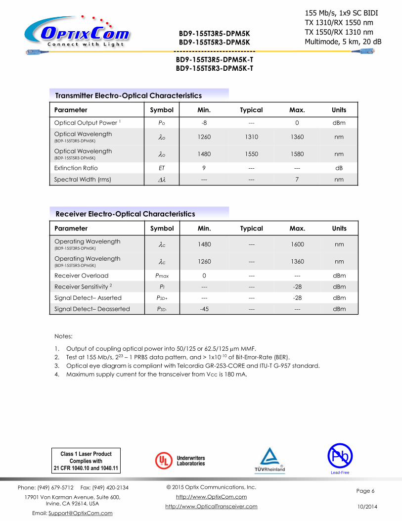
Transmitter Electro-Optical Characteristics
Parameter Symbol Min. Typical Max. Units
Optical Output Power 1 Po -8 --- 0 dBm
Optical Wavelength (BD9-155T3R5-DPM5K)
lo 1260 1310 1360 nm
Optical Wavelength (BD9-155T5R3-DPM5K)
lo 1480 1550 1580 nm
Extinction Ratio ET 9 --- --- dB
Spectral Width (rms) Dl --- --- 7 nm
Receiver Electro-Optical Characteristics
Parameter Symbol Min. Typical Max. Units
Operating Wavelength (BD9-155T3R5-DPM5K)
lc 1480 --- 1600 nm
Operating Wavelength (BD9-155T5R3-DPM5K)
lc 1260 --- 1360 nm
Receiver Overload Pmax 0 --- --- dBm
Receiver Sensitivity 2 PI --- --- -28 dBm
Signal Detect– Asserted PSD+ --- --- -28 dBm
Signal Detect– Deasserted PSD- -45 --- --- dBm
Notes:
1. Output of coupling optical power into 50/125 or 62.5/125 mm MMF.
2. Test at 155 Mb/s, 223 – 1 PRBS data pattern, and > 1x10⁻¹⁰ of Bit-Error-Rate (BER).
3. Optical eye diagram is compliant with Telcordia GR-253-CORE and ITU-T G-957 standard.
4. Maximum supply current for the transceiver from Vcc is 180 mA.
Class 1 Laser Product
Complies with
21 CFR 1040.10 and 1040.11
Pb
Lead-Free
BD9-155T3R5-DPM5K BD9-155T5R3-DPM5K
--------------------------- BD9-155T3R5-DPM5K-T BD9-155T5R3-DPM5K-T
Phone: (949) 679-5712 Fax: (949) 420-2134
17901 Von Karman Avenue, Suite 600, Irvine, CA 92614, USA
Email: [email protected]
© 2015 Optix Communications, Inc.
http://www.OptixCom.com
http://www.OpticalTransceiver.com
Page 7
10/2014
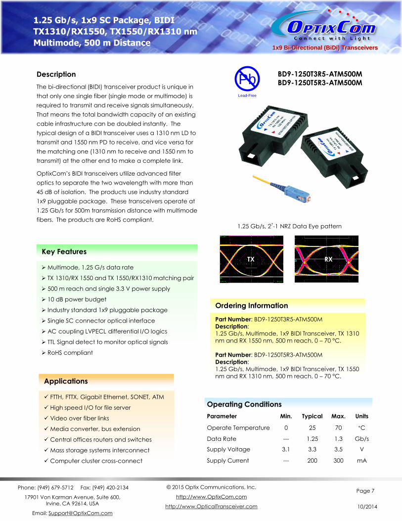
1x9 Bi-Directional (BiDi) Transceivers
Description
The bi-directional (BIDI) transceiver product is unique in
that only one single fiber (single mode or multimode) is
required to transmit and receive signals simultaneously.
That means the total bandwidth capacity of an existing
cable infrastructure can be doubled instantly. The
typical design of a BIDI transceiver uses a 1310 nm LD to
transmit and 1550 nm PD to receive, and vice versa for
the matching one (1310 nm to receive and 1550 nm to
transmit) at the other end to make a complete link.
OptixCom’s BIDI transceivers utilize advanced filter
optics to separate the two wavelength with more than
45 dB of isolation. The products use industry standard
1x9 pluggable package. These transceivers operate at
1.25 Gb/s for 500m transmission distance with multimode
fibers. The products are RoHS compliant.
Key Features
Multimode, 1.25 G/s data rate
TX 1310/RX 1550 and TX 1550/RX1310 matching pair
500 m reach and single 3.3 V power supply
10 dB power budget
Industry standard 1x9 pluggable package
Single SC connector optical interface
AC coupling LVPECL differential I/O logics
TTL Signal detect to monitor optical signals
RoHS compliant
BD9-1250T3R5-ATM500M BD9-1250T5R3-ATM500M
Ordering Information
Part Number: BD9-1250T3R5-ATM500M
Description:
1.25 Gb/s, Multimode, 1x9 BIDI Transceiver, TX 1310
nm and RX 1550 nm, 500 m reach, 0 – 70 °C.
Part Number: BD9-1250T5R3-ATM500M
Description:
1.25 Gb/s, Multimode, 1x9 BIDI Transceiver, TX 1550
nm and RX 1310 nm, 500 m reach, 0 – 70 °C.
Operating Conditions
Parameter Min. Typical Max. Units
Operate Temperature 0 25 70 °C
Data Rate --- 1.25 1.3 Gb/s
Supply Voltage 3.1 3.3 3.5 V
Supply Current --- 200 300 mA
1.25 Gb/s, 1x9 SC Package, BIDI
TX1310/RX1550, TX1550/RX1310 nm
Multimode, 500 m Distance
Pb
Lead-Free
TX RX
1.25 Gb/s, 27-1 NRZ Data Eye pattern
Applications
FTTH, FTTX, Gigabit Ethernet, SONET, ATM
High speed I/O for file server
Video over fiber links
Media converter, bus extension
Central offices routers and switches
Mass storage systems interconnect
Computer cluster cross-connect
Phone: (949) 679-5712 Fax: (949) 420-2134
17901 Von Karman Avenue, Suite 600, Irvine, CA 92614, USA
Email: [email protected]
© 2015 Optix Communications, Inc.
http://www.OptixCom.com
http://www.OpticalTransceiver.com
Page 8
10/2014
Absolute Maximum Ratings
Parameter Symbol Min. Max. Units
Storage Temperature Tst -40 85 °C
Supply Voltage Vcc -0.5 6.0 V
Input Voltage VIN -0.5 Vcc V
Operating Current Iop --- 400 mA
Output Current Io --- 50 mA
Soldering Temperature (10 sec. on leads) Tsd --- 260 °C
1.25 Gb/s, 1x9 SC BIDI
TX 1310/RX 1550 nm
TX 1550/RX 1310 nm
Multimode, 500m BD9-1250T3R5-ATM500M BD9-1250T5R3-ATM500M
General Transmitter Characteristics (FP Laser)
Parameter Symbol Min. Typical Max. Units
Differential Input Voltage 1 DVi 0.3 --- 1.6 V
Differential Input Impedance 2 Z --- 100 --- ohm
Relative Intensity Noise RIN --- --- -120 dB/Hz
Rise/Fall Time (20% - 80%) Tr/Tf --- --- 260 ps
Data Input Current - High IIH --- --- 350 mA
Data Input Current - Low IIL -350 --- --- mA
Side Mode Suppression Ratio SMSR 30 --- --- dB
Notes:
1. Module is designed for AC LVPECL coupling. See the design guide for proper termination.
2. Single ended will be 50 ohm for each signal line.
General Receiver Characteristics
Parameter Symbol Min. Typical Max. Units
Differential Output Voltage 1 DVo 1.0 --- 1.8 V
Differential Input Impedance 2 Z --- 100 --- Ohm
Optical Return Loss OL 14 --- --- dB
Rise/Fall Time (20% - 80%) Tr/Tf --- --- 350 ps
Signal Detect Hysteresis PSD+ - PSD 1 --- --- dB
Crosstalk --- --- -45 dB
Signal Detect Output - High VSD+ 2.4 --- Vcc V
Signal Detect Output - Low VSD- 0 --- 0.5 V
Phone: (949) 679-5712 Fax: (949) 420-2134
17901 Von Karman Avenue, Suite 600, Irvine, CA 92614, USA
Email: [email protected]
© 2015 Optix Communications, Inc.
http://www.OptixCom.com
http://www.OpticalTransceiver.com
Page 9
10/2014
Transmitter Electro-Optical Characteristics
Parameter Symbol Min. Typical Max. Units
Optical Output Power 1 Po -8 --- 0 dBm
Optical Wavelength (BD9-1250T3R5-ATM500M)
lo 1260 1310 1360 nm
Optical Wavelength (BD9-1250T5R3-ATM500M)
lo 1480 1550 1580 nm
Extinction Ratio ET 9 --- --- dB
Spectral Width (rms) Dl --- --- 4 nm
Receiver Electro-Optical Characteristics
Parameter Symbol Min. Typical Max. Units
Operating Wavelength (BD9-1250T3R5-ATM500M)
lc 1500 --- 1600 nm
Operating Wavelength (BD9-1250T5R3-ATM500M)
lc 1260 --- 1360 nm
Receiver Overload Pmax 0 --- --- dBm
Receiver Sensitivity 2 PI --- --- -18 dBm
Signal Detect– Asserted PSD+ --- --- -18 dBm
Signal Detect– Deasserted PSD- -35 --- --- dBm
Notes:
1. Output of coupling optical power into 50/125 or 62.5/125 mm MMF.
2. Test at 1.25 Gb/s, 27 – 1 PRBS data pattern, and > 1x10-12 of Bit-Error-Rate (BER).
3. Optical eye diagram is compliant with IEEE 802.3z standard.
4. Maximum supply current for the transceiver from Vcc is 300 mA.
Class 1 Laser Product
Complies with
21 CFR 1040.10 and 1040.11
Pb
Lead-Free
1.25 Gb/s, 1x9 SC BIDI
TX 1310/RX 1550 nm
TX 1550/RX 1310 nm
Multimode, 500m BD9-1250T3R5-ATM500M BD9-1250T5R3-ATM500M
Phone: (949) 679-5712 Fax: (949) 420-2134
17901 Von Karman Avenue, Suite 600, Irvine, CA 92614, USA
Email: [email protected]
© 2015 Optix Communications, Inc.
http://www.OptixCom.com
http://www.OpticalTransceiver.com
Page 10
10/2014
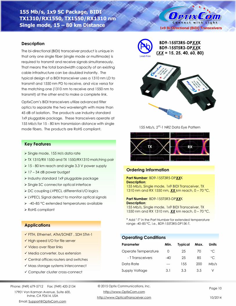
1x9 Bi-Directional (BiDi) Transceivers
Description
The bi-directional (BIDI) transceiver product is unique in
that only one single fiber (single mode or multimode) is
required to transmit and receive signals simultaneously.
That means the total bandwidth capacity of an existing
cable infrastructure can be doubled instantly. The
typical design of a BIDI transceiver uses a 1310 nm LD to
transmit and 1550 nm PD to receive, and vice versa for
the matching one (1310 nm to receive and 1550 nm to
transmit) at the other end to make a complete link.
OptixCom’s BIDI transceivers utilize advanced filter
optics to separate the two wavelength with more than
45 dB of isolation. The products use industry standard
1x9 pluggable package. These transceivers operate at
155 Mb/s for 15 - 80 km transmission distance with single
mode fibers. The products are RoHS compliant.
Key Features
Applications
FTTH, Ethernet, ATM/SONET , SDH STM-1
High speed I/O for file server
Video over fiber links
Media converter, bus extension
Central offices routers and switches
Mass storage systems interconnect
Computer cluster cross-connect
Single mode, 155 M/s data rate
TX 1310/RX 1550 and TX 1550/RX1310 matching pair
15 - 80 km reach and single 3.3 V power supply
17 – 34 dB power budget
Industry standard 1x9 pluggable package
Single SC connector optical interface
DC coupling LVPECL differential I/O logics
LVPECL Signal detect to monitor optical signals
-40–85 °C extended temperatures available
RoHS compliant
BD9-155T3R5-DPXXK BD9-155T5R3-DPXXK
(XX = 15, 25, 40, 60, 80)
Ordering Information
Part Number: BD9-155T3R5-DPXXK
Description:
155 Mb/s, Single mode, 1x9 BIDI Transceiver, TX
1310 nm and RX 1550 nm, XX km reach, 0 – 70 °C.
Part Number: BD9-155T5R3-DPXXK
Description:
155 Mb/s, Single mode, 1x9 BIDI Transceiver, TX
1550 nm and RX 1310 nm, XX km reach, 0 – 70 °C.
* Add "-T" in the Part Number for extended temperature
range -40–85 °C, i.e., BD9-155T3R5-DP15K-T.
Operating Conditions
Parameter Min. Typical Max. Units
Operate Temperature 0 25 70 °C
- T Transceivers -40 25 85 °C
Data Rate --- 155 200 Mb/s
Supply Voltage 3.1 3.3 3.5 V
155 Mb/s, 1x9 SC Package, BIDI
TX1310/RX1550, TX1550/RX1310 nm
Single mode, 15 – 80 km Distance
TX RX
Pb
Lead-Free
155 Mb/s, 223-1 NRZ Data Eye Pattern
Phone: (949) 679-5712 Fax: (949) 420-2134
17901 Von Karman Avenue, Suite 600, Irvine, CA 92614, USA
Email: [email protected]
© 2015 Optix Communications, Inc.
http://www.OptixCom.com
http://www.OpticalTransceiver.com
Page 11
10/2014
Absolute Maximum Ratings
Parameter Symbol Min. Max. Units
Storage Temperature Tst -40 85 °C
Supply Voltage Vcc -0.5 4.0 V
Input Voltage VIN -0.5 Vcc V
Operating Current Iop --- 400 mA
Output Current Io --- 50 mA
Soldering Temperature (10 sec. on leads) Tsd --- 260 °C
General Transmitter Characteristics
Parameter Symbol Min. Typical Max. Units
Differential Input Voltage 1 DVi 0.3 --- 1.6 V
Differential Input Impedance 2 Z --- 100 --- ohm
Relative Intensity Noise RIN --- --- -120 dB/Hz
Rise/Fall Time (10% - 90%) Tr/Tf --- 1 2 ns
Data Input Current - High IIH --- --- 350 mA
Data Input Current - Low IIL -350 --- --- mA
Data Input Voltage – High VIH Vcc - 1.1 --- Vcc – 0.7 V
Data Input Voltage - Low VIL Vcc – 2.0 --- Vcc - 1.6 V
Notes:
1. Module is designed for DC LVPECL coupling. See the design guide for proper termination.
2. Single ended will be 50 ohm for each signal line.
155 Mb/s, 1x9 SC BIDI
TX 1310/RX 1550 nm
TX 1550/RX 1310 nm
Single mode, 15 – 80 km BD9-155T3R5-DPXXK BD9-155T5R3-DPXXK
General Receiver Characteristics
Parameter Symbol Min. Typical Max. Units
Differential Output Voltage 1 DVo 0.3 --- 1.6 V
Differential Input Impedance 2 Z --- 100 --- Ohm
Optical Return Loss OL 14 --- --- dB
Rise/Fall Time (10% - 90%) Tr/Tf --- 1 2 ns
Signal Detect Hysteresis PSD+ - PSD 1 --- --- dB
Crosstalk --- --- -45 dB
Signal Detect Output - High VSD+ Vcc - 1.1 --- Vcc – 0.7 V
Signal Detect Output - Low VSD- Vcc – 2.0 --- Vcc - 1.6 V
Data Output Voltage – High VOH Vcc - 1.1 --- Vcc – 0.7 V
Data Output Voltage – Low VOL Vcc – 2.0 --- Vcc - 1.6 V
Phone: (949) 679-5712 Fax: (949) 420-2134
17901 Von Karman Avenue, Suite 600, Irvine, CA 92614, USA
Email: [email protected]
© 2015 Optix Communications, Inc.
http://www.OptixCom.com
http://www.OpticalTransceiver.com
Page 12
10/2014
155 Mb/s, 1x9 SC BIDI
TX 1310/RX 1550 nm
TX 1550/RX 1310 nm
Single mode, 15 km, 17 dB
Transmitter Electro-Optical Characteristics (FP Laser)
Parameter Symbol Min. Typical Max. Units
Optical Output Power 1 Po -14 --- -8 dBm
Optical Wavelength (BD9-155T3R5-DP15K)
lo 1260 1310 1360 nm
Optical Wavelength (BD9-155T5R3-DP15K)
lo 1480 1550 1580 nm
Extinction Ratio ET 9 --- --- dB
Spectral Width (rms) (BD9-155T3R5-DP15K)
Dl --- --- 4 nm
Spectral Width (rms) (BD9-155T5R3-DP15K)
Dl --- --- 3 nm
Receiver Electro-Optical Characteristics
Parameter Symbol Min. Typical Max. Units
Operating Wavelength (BD9-155T3R5-DP15K)
lc 1480 --- 1600 nm
Operating Wavelength (BD9-155T5R3-DP15K)
lc 1260 --- 1360 nm
Receiver Overload Pmax 0 --- --- dBm
Receiver Sensitivity 2 PI --- --- -31 dBm
Signal Detect– Asserted PSD+ --- --- -31 dBm
Signal Detect– Deasserted PSD- -45 --- --- dBm
Notes:
1. Output of coupling optical power into 9/125 mm SMF.
2. Test at 155 Mb/s, 223 – 1 PRBS data pattern, and > 1x10⁻¹⁰ of Bit-Error-Rate (BER).
3. Optical eye diagram is compliant with Telcordia GR-253-CORE and ITU-T G-957 standard.
4. Maximum supply current for the transceiver from Vcc is 200 mA.
Class 1 Laser Product
Complies with
21 CFR 1040.10 and 1040.11
Pb
Lead-Free
BD9-155T3R5-DP15K BD9-155T5R3-DP15K
--------------------------- BD9-155T3R5-DP15K-T BD9-155T5R3-DP15K-T
Phone: (949) 679-5712 Fax: (949) 420-2134
17901 Von Karman Avenue, Suite 600, Irvine, CA 92614, USA
Email: [email protected]
© 2015 Optix Communications, Inc.
http://www.OptixCom.com
http://www.OpticalTransceiver.com
Page 13
10/2014
Transmitter Electro-Optical Characteristics (FP Laser)
Parameter Symbol Min. Typical Max. Units
Optical Output Power 1 Po -9 --- -3 dBm
Optical Wavelength (BD9-155T3R5-DP25K)
lo 1260 1310 1360 nm
Optical Wavelength (BD9-155T5R3-DP25K)
lo 1480 1550 1580 nm
Extinction Ratio ET 9 --- --- dB
Spectral Width (rms) (BD9-155T3R5-DP25K)
Dl --- --- 4 nm
Spectral Width (rms) (BD9-155T5R3-DP25K)
Dl --- --- 3 nm
Receiver Electro-Optical Characteristics
Parameter Symbol Min. Typical Max. Units
Operating Wavelength (BD9-155T3R5-DP25K)
lc 1480 --- 1600 nm
Operating Wavelength (BD9-155T5R3-DP25K)
lc 1260 --- 1360 nm
Receiver Overload Pmax 0 --- --- dBm
Receiver Sensitivity 2 PI --- --- -31 dBm
Signal Detect– Asserted PSD+ --- --- -31 dBm
Signal Detect– Deasserted PSD- -45 --- --- dBm
Notes:
1. Output of coupling optical power into 9/125 mm SMF.
2. Test at 155 Mb/s, 223 – 1 PRBS data pattern, and > 1x10⁻¹⁰ of Bit-Error-Rate (BER).
3. Optical eye diagram is compliant with Telcordia GR-253-CORE and ITU-T G-957 standard.
4. Maximum supply current for the transceiver from Vcc is 200 mA.
Class 1 Laser Product
Complies with
21 CFR 1040.10 and 1040.11
Pb
Lead-Free
BD9-155T3R5-DP25K BD9-155T5R3-DP25K
--------------------------- BD9-155T3R5-DP25K-T BD9-155T5R3-DP25K-T
155 Mb/s, 1x9 SC BIDI
TX 1310/RX 1550 nm
TX 1550/RX 1310 nm
Single mode, 25 km, 22 dB
Phone: (949) 679-5712 Fax: (949) 420-2134
17901 Von Karman Avenue, Suite 600, Irvine, CA 92614, USA
Email: [email protected]
© 2015 Optix Communications, Inc.
http://www.OptixCom.com
http://www.OpticalTransceiver.com
Page 14
10/2014
Transmitter Electro-Optical Characteristics (DFB Laser)
Parameter Symbol Min. Typical Max. Units
Optical Output Power 1 Po -8 --- 0 dBm
Optical Wavelength (BD9-155T3R5-DP40K)
lo 1280 1310 1355 nm
Optical Wavelength (BD9-155T5R3-DP40K)
lo 1530 1550 1570 nm
Extinction Ratio ET 9 --- --- dB
Spectral Width (rms) (BD9-155T3R5-DP40K)
Dl --- --- 2.5 nm
Spectral Width (-20 dB) (BD9-155T5R3-DP40K)
Dl --- --- 1 nm
Side Mode Suppression Ratio SMSR 30 --- --- dB
Receiver Electro-Optical Characteristics
Parameter Symbol Min. Typical Max. Units
Operating Wavelength (BD9-155T3R5-DP40K)
lc 1480 --- 1600 nm
Operating Wavelength (BD9-155T5R3-DP40K)
lc 1260 --- 1360 nm
Receiver Overload Pmax 0 --- --- dBm
Receiver Sensitivity 2 PI --- --- -34 dBm
Signal Detect– Asserted PSD+ --- --- -34 dBm
Signal Detect– Deasserted PSD- -45 --- --- dBm
Notes:
1. Output of coupling optical power into 9/125 mm SMF.
2. Test at 155 Mb/s, 223 – 1 PRBS data pattern, and > 1x10⁻¹⁰ of Bit-Error-Rate (BER).
3. Optical eye diagram is compliant with Telcordia GR-253-CORE and ITU-T G-957 standard.
4. Maximum supply current for the transceiver from Vcc is 250 mA.
Class 1 Laser Product
Complies with
21 CFR 1040.10 and 1040.11
Pb
Lead-Free
BD9-155T3R5-DP40K BD9-155T5R3-DP40K
--------------------------- BD9-155T3R5-DP40K-T BD9-155T5R3-DP40K-T
155 Mb/s, 1x9 SC BIDI
TX 1310/RX 1550 nm
TX 1550/RX 1310 nm
Single mode, 40 km, 26 dB
Phone: (949) 679-5712 Fax: (949) 420-2134
17901 Von Karman Avenue, Suite 600, Irvine, CA 92614, USA
Email: [email protected]
© 2015 Optix Communications, Inc.
http://www.OptixCom.com
http://www.OpticalTransceiver.com
Page 15
10/2014
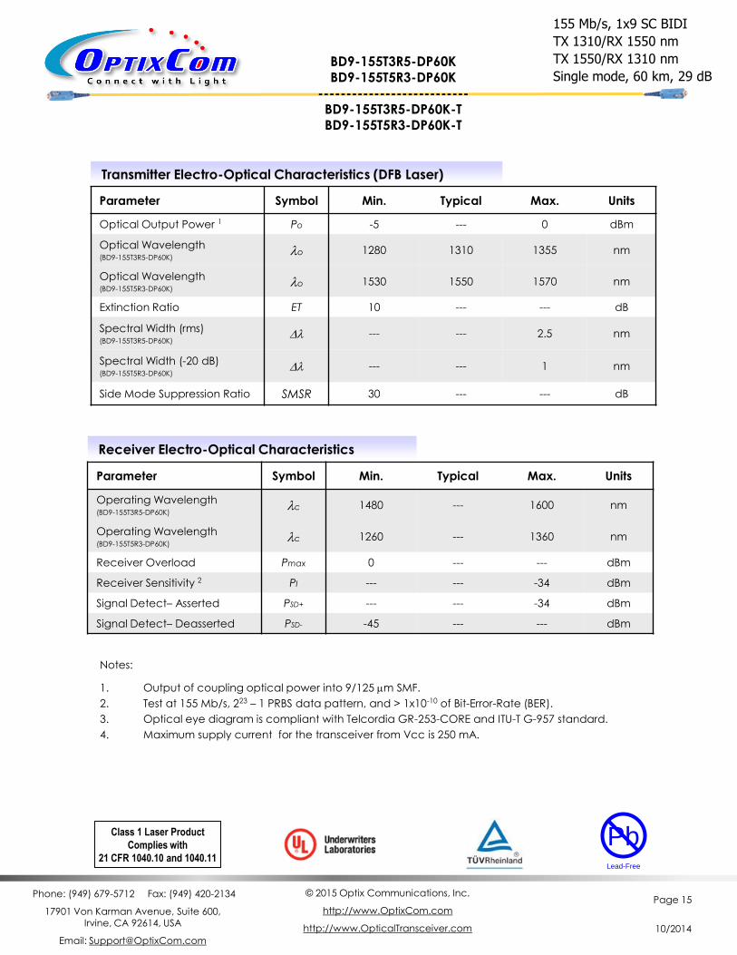
Transmitter Electro-Optical Characteristics (DFB Laser)
Parameter Symbol Min. Typical Max. Units
Optical Output Power 1 Po -5 --- 0 dBm
Optical Wavelength (BD9-155T3R5-DP60K)
lo 1280 1310 1355 nm
Optical Wavelength (BD9-155T5R3-DP60K)
lo 1530 1550 1570 nm
Extinction Ratio ET 10 --- --- dB
Spectral Width (rms) (BD9-155T3R5-DP60K)
Dl --- --- 2.5 nm
Spectral Width (-20 dB) (BD9-155T5R3-DP60K)
Dl --- --- 1 nm
Side Mode Suppression Ratio SMSR 30 --- --- dB
Receiver Electro-Optical Characteristics
Parameter Symbol Min. Typical Max. Units
Operating Wavelength (BD9-155T3R5-DP60K)
lc 1480 --- 1600 nm
Operating Wavelength (BD9-155T5R3-DP60K)
lc 1260 --- 1360 nm
Receiver Overload Pmax 0 --- --- dBm
Receiver Sensitivity 2 PI --- --- -34 dBm
Signal Detect– Asserted PSD+ --- --- -34 dBm
Signal Detect– Deasserted PSD- -45 --- --- dBm
Notes:
1. Output of coupling optical power into 9/125 mm SMF.
2. Test at 155 Mb/s, 223 – 1 PRBS data pattern, and > 1x10⁻¹⁰ of Bit-Error-Rate (BER).
3. Optical eye diagram is compliant with Telcordia GR-253-CORE and ITU-T G-957 standard.
4. Maximum supply current for the transceiver from Vcc is 250 mA.
Class 1 Laser Product
Complies with
21 CFR 1040.10 and 1040.11
Pb
Lead-Free
BD9-155T3R5-DP60K BD9-155T5R3-DP60K
--------------------------- BD9-155T3R5-DP60K-T BD9-155T5R3-DP60K-T
155 Mb/s, 1x9 SC BIDI
TX 1310/RX 1550 nm
TX 1550/RX 1310 nm
Single mode, 60 km, 29 dB
Phone: (949) 679-5712 Fax: (949) 420-2134
17901 Von Karman Avenue, Suite 600, Irvine, CA 92614, USA
Email: [email protected]
© 2015 Optix Communications, Inc.
http://www.OptixCom.com
http://www.OpticalTransceiver.com
Page 16
10/2014
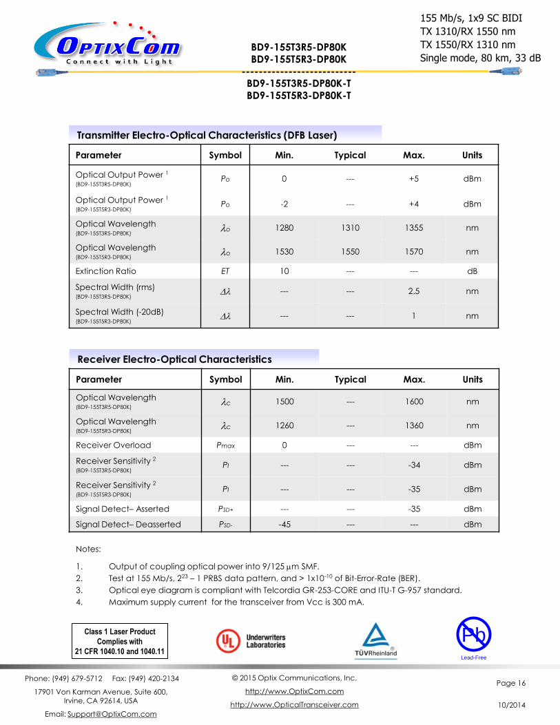
Transmitter Electro-Optical Characteristics (DFB Laser)
Parameter Symbol Min. Typical Max. Units
Optical Output Power 1
(BD9-155T3R5-DP80K) Po 0 --- +5 dBm
Optical Output Power 1
(BD9-155T5R3-DP80K) Po -2 --- +4 dBm
Optical Wavelength (BD9-155T3R5-DP80K)
lo 1280 1310 1355 nm
Optical Wavelength (BD9-155T5R3-DP80K)
lo 1530 1550 1570 nm
Extinction Ratio ET 10 --- --- dB
Spectral Width (rms) (BD9-155T3R5-DP80K)
Dl --- --- 2.5 nm
Spectral Width (-20dB) (BD9-155T5R3-DP80K)
Dl --- --- 1 nm
Receiver Electro-Optical Characteristics
Parameter Symbol Min. Typical Max. Units
Optical Wavelength (BD9-155T3R5-DP80K)
lc 1500 --- 1600 nm
Optical Wavelength (BD9-155T5R3-DP80K)
lc 1260 --- 1360 nm
Receiver Overload Pmax 0 --- --- dBm
Receiver Sensitivity 2
(BD9-155T3R5-DP80K) PI --- --- -34 dBm
Receiver Sensitivity 2
(BD9-155T5R3-DP80K) PI --- --- -35 dBm
Signal Detect– Asserted PSD+ --- --- -35 dBm
Signal Detect– Deasserted PSD- -45 --- --- dBm
Class 1 Laser Product
Complies with
21 CFR 1040.10 and 1040.11
Pb
Lead-Free
Notes:
1. Output of coupling optical power into 9/125 mm SMF.
2. Test at 155 Mb/s, 223 – 1 PRBS data pattern, and > 1x10⁻¹⁰ of Bit-Error-Rate (BER).
3. Optical eye diagram is compliant with Telcordia GR-253-CORE and ITU-T G-957 standard.
4. Maximum supply current for the transceiver from Vcc is 300 mA.
BD9-155T3R5-DP80K BD9-155T5R3-DP80K
--------------------------- BD9-155T3R5-DP80K-T BD9-155T5R3-DP80K-T
155 Mb/s, 1x9 SC BIDI
TX 1310/RX 1550 nm
TX 1550/RX 1310 nm
Single mode, 80 km, 33 dB

Phone: (949) 679-5712 Fax: (949) 420-2134
17901 Von Karman Avenue, Suite 600, Irvine, CA 92614, USA
Email: [email protected]
© 2015 Optix Communications, Inc.
http://www.OptixCom.com
http://www.OpticalTransceiver.com
Page 17
10/2014
1x9 Bi-Directional (BiDi) Transceivers
Description
The bi-directional (BIDI) transceiver product is unique in
that only one single fiber (single mode or multimode) is
required to transmit and receive signals simultaneously.
That means the total bandwidth capacity of an existing
cable infrastructure can be doubled instantly. The
typical design of a BIDI transceiver uses a 1510 nm LD to
transmit and 1570 nm PD to receive, and vice versa for
the matching one (1510 nm to receive and 1570 nm to
transmit) at the other end to make a complete link.
OptixCom’s BIDI transceivers utilize advanced filter
optics to separate the two wavelength with more than
45 dB of isolation. The products use industry standard
1x9 pluggable package. These transceivers operate at
155 Mb/s for 100 - 120 km transmission distance with
single mode fibers. The products are RoHS compliant.
Key Features
Applications
FTTH, Ethernet, ATM/SONET , SDH STM-1
High speed I/O for file server
Video over fiber links
Media converter, bus extension
Central offices routers and switches
Mass storage systems interconnect
Computer cluster cross-connect
Single mode, 155 M/s data rate
TX 1510/RX 1570 and TX 1570/RX1510 matching pair
100 - 120 km reach and single 3.3 V power supply
28 – 32 dB power budget
Industry standard 1x9 pluggable package
Single SC connector optical interface
DC coupling LVPECL differential I/O logics
LVPECL Signal detect to monitor optical signals
RoHS compliant
BD9-155T1R7-DPXXXK BD9-155T7R1-DPXXXK
(XXX = 100, 120)
Ordering Information
Part Number: BD9-155T1R7-DPXXXK
Description:
155 Mb/s, Single mode, 1x9 BIDI Transceiver, TX
1510 nm and RX 1570 nm, XXX km reach, 0 – 70 °C.
Part Number: BD9-155T7R1-DPXXXK
Description:
155 Mb/s, Single mode, 1x9 BIDI Transceiver, TX
1570 nm and RX 1510 nm, XXX km reach, 0 – 70 °C.
Operating Conditions
Parameter Min. Typical Max. Units
Operate Temperature 0 25 70 °C
Data Rate --- 155 200 Mb/s
Supply Voltage 3.1 3.3 3.5 V
Supply Current --- 200 300 mA
155 Mb/s, 1x9 SC Package, BIDI
TX1510/RX1570, TX1570/RX1510 nm
Single mode, 100 – 120 km Distance
TX RX
Pb
Lead-Free
155 Mb/s, 223-1 NRZ Data Eye Pattern
Phone: (949) 679-5712 Fax: (949) 420-2134
17901 Von Karman Avenue, Suite 600, Irvine, CA 92614, USA
Email: [email protected]
© 2015 Optix Communications, Inc.
http://www.OptixCom.com
http://www.OpticalTransceiver.com
Page 18
10/2014
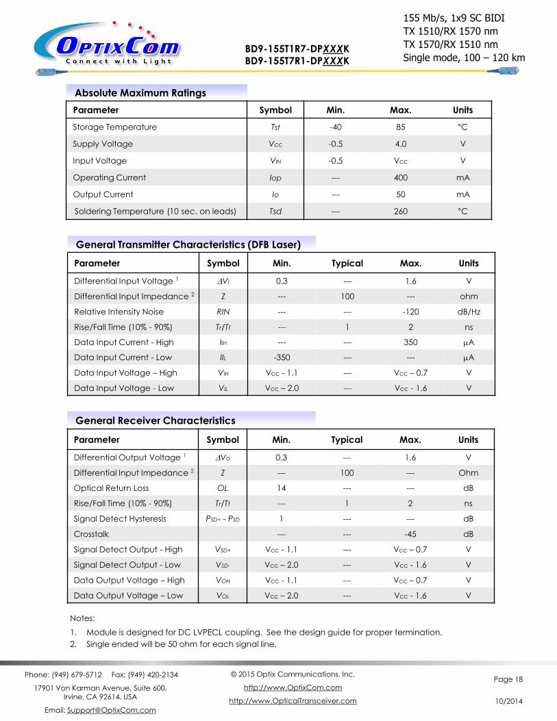
Absolute Maximum Ratings
Parameter Symbol Min. Max. Units
Storage Temperature Tst -40 85 °C
Supply Voltage Vcc -0.5 4.0 V
Input Voltage VIN -0.5 Vcc V
Operating Current Iop --- 400 mA
Output Current Io --- 50 mA
Soldering Temperature (10 sec. on leads) Tsd --- 260 °C
General Transmitter Characteristics (DFB Laser)
Parameter Symbol Min. Typical Max. Units
Differential Input Voltage 1 DVi 0.3 --- 1.6 V
Differential Input Impedance 2 Z --- 100 --- ohm
Relative Intensity Noise RIN --- --- -120 dB/Hz
Rise/Fall Time (10% - 90%) Tr/Tf --- 1 2 ns
Data Input Current - High IIH --- --- 350 mA
Data Input Current - Low IIL -350 --- --- mA
Data Input Voltage – High VIH Vcc - 1.1 --- Vcc – 0.7 V
Data Input Voltage - Low VIL Vcc – 2.0 --- Vcc - 1.6 V
Notes:
1. Module is designed for DC LVPECL coupling. See the design guide for proper termination.
2. Single ended will be 50 ohm for each signal line.
155 Mb/s, 1x9 SC BIDI
TX 1510/RX 1570 nm
TX 1570/RX 1510 nm
Single mode, 100 – 120 km BD9-155T1R7-DPXXXK BD9-155T7R1-DPXXXK
General Receiver Characteristics
Parameter Symbol Min. Typical Max. Units
Differential Output Voltage 1 DVo 0.3 --- 1.6 V
Differential Input Impedance 2 Z --- 100 --- Ohm
Optical Return Loss OL 14 --- --- dB
Rise/Fall Time (10% - 90%) Tr/Tf --- 1 2 ns
Signal Detect Hysteresis PSD+ - PSD 1 --- --- dB
Crosstalk --- --- -45 dB
Signal Detect Output - High VSD+ Vcc - 1.1 --- Vcc – 0.7 V
Signal Detect Output - Low VSD- Vcc – 2.0 --- Vcc - 1.6 V
Data Output Voltage – High VOH Vcc - 1.1 --- Vcc – 0.7 V
Data Output Voltage – Low VOL Vcc – 2.0 --- Vcc - 1.6 V

Phone: (949) 679-5712 Fax: (949) 420-2134
17901 Von Karman Avenue, Suite 600, Irvine, CA 92614, USA
Email: [email protected]
© 2015 Optix Communications, Inc.
http://www.OptixCom.com
http://www.OpticalTransceiver.com
Page 19
10/2014
Transmitter Electro-Optical Characteristics
Parameter Symbol Min. Typical Max. Units
Optical Output Power 1 Po -5 --- +2 dBm
Optical Wavelength (BD9-155T1R7-DP100K)
lo 1500 1510 1520 nm
Optical Wavelength (BD9-155T7R1-DP100K)
lo 1560 1570 1580 nm
Extinction Ratio ET 9 --- --- dB
Spectral Width (rms) Dl --- --- 1 nm
Receiver Electro-Optical Characteristics
Parameter Symbol Min. Typical Max. Units
Operating Wavelength (BD9-155T1R7-DP100K)
lc 1560 1570 1580 nm
Operating Wavelength (BD9-155T7R1-DP100K)
lc 1500 1510 1520 nm
Receiver Overload Pmax 0 --- --- dBm
Receiver Sensitivity 2 PI --- --- -33 dBm
Signal Detect– Asserted PSD+ --- --- -33 dBm
Signal Detect– Deasserted PSD- -45 --- --- dBm
Notes:
1. Output of coupling optical power into 9/125 mm SMF.
2. Test at 155 Mb/s, 223 – 1 PRBS data pattern, and > 1x10⁻¹⁰ of Bit-Error-Rate (BER).
3. Optical eye diagram is compliant with Telcordia GR-253-CORE and ITU-T G-957 standard.
4. Maximum supply current for the transceiver from Vcc is 300 mA.
Class 1 Laser Product
Complies with
21 CFR 1040.10 and 1040.11
Pb
Lead-Free
155 Mb/s, 1x9 SC BIDI
TX 1510/RX 1570 nm
TX 1570/RX 1510 nm
Single mode, 100 km BD9-155T1R7-DP100K BD9-155T7R1-DP100K
Phone: (949) 679-5712 Fax: (949) 420-2134
17901 Von Karman Avenue, Suite 600, Irvine, CA 92614, USA
Email: [email protected]
© 2015 Optix Communications, Inc.
http://www.OptixCom.com
http://www.OpticalTransceiver.com
Page 20
10/2014
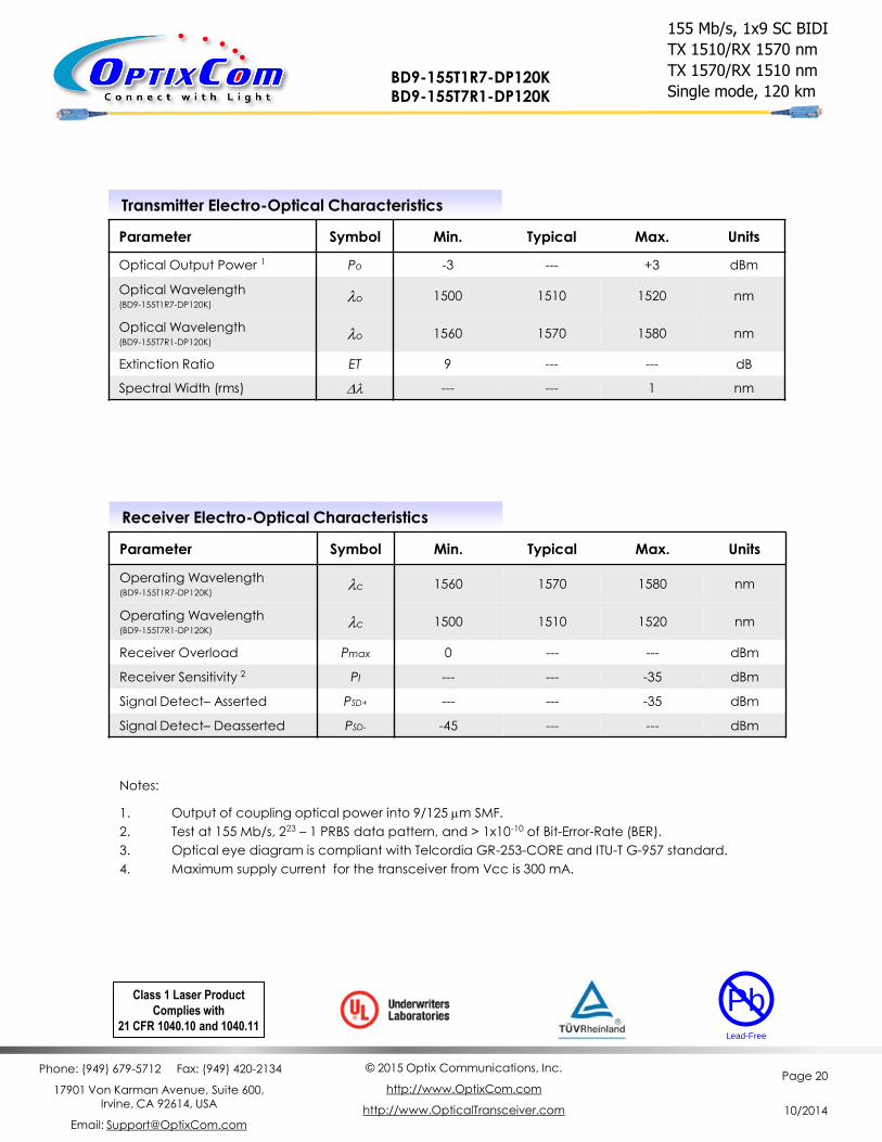
Transmitter Electro-Optical Characteristics
Parameter Symbol Min. Typical Max. Units
Optical Output Power 1 Po -3 --- +3 dBm
Optical Wavelength (BD9-155T1R7-DP120K)
lo 1500 1510 1520 nm
Optical Wavelength (BD9-155T7R1-DP120K)
lo 1560 1570 1580 nm
Extinction Ratio ET 9 --- --- dB
Spectral Width (rms) Dl --- --- 1 nm
Receiver Electro-Optical Characteristics
Parameter Symbol Min. Typical Max. Units
Operating Wavelength (BD9-155T1R7-DP120K)
lc 1560 1570 1580 nm
Operating Wavelength (BD9-155T7R1-DP120K)
lc 1500 1510 1520 nm
Receiver Overload Pmax 0 --- --- dBm
Receiver Sensitivity 2 PI --- --- -35 dBm
Signal Detect– Asserted PSD+ --- --- -35 dBm
Signal Detect– Deasserted PSD- -45 --- --- dBm
Notes:
1. Output of coupling optical power into 9/125 mm SMF.
2. Test at 155 Mb/s, 223 – 1 PRBS data pattern, and > 1x10⁻¹⁰ of Bit-Error-Rate (BER).
3. Optical eye diagram is compliant with Telcordia GR-253-CORE and ITU-T G-957 standard.
4. Maximum supply current for the transceiver from Vcc is 300 mA.
Class 1 Laser Product
Complies with
21 CFR 1040.10 and 1040.11
Pb
Lead-Free
155 Mb/s, 1x9 SC BIDI
TX 1510/RX 1570 nm
TX 1570/RX 1510 nm
Single mode, 120 km BD9-155T1R7-DP120K BD9-155T7R1-DP120K

Phone: (949) 679-5712 Fax: (949) 420-2134
17901 Von Karman Avenue, Suite 600, Irvine, CA 92614, USA
Email: [email protected]
© 2015 Optix Communications, Inc.
http://www.OptixCom.com
http://www.OpticalTransceiver.com
Page 21
10/2014
1x9 Bi-Directional (BiDi) Transceivers
Description
The bi-directional (BIDI) transceiver product is unique in
that only one single fiber (single mode or multimode) is
required to transmit and receive signals simultaneously.
That means the total bandwidth capacity of an existing
cable infrastructure can be doubled instantly. The
typical design of a BIDI transceiver uses a 1310 nm LD to
transmit and 1550 nm PD to receive, and vice versa for
the matching one (1310 nm to receive and 1550 nm to
transmit) at the other end to make a complete link.
OptixCom’s BIDI transceivers utilize advanced filter
optics to separate the two wavelength with more than
45 dB of isolation. The products use industry standard
1x9 pluggable package. These transceivers operate at
1.25 Gb/s for 15 - 60 km transmission distance with single
mode fibers. The products are RoHS compliant.
Key Features
Single mode, 1.25 G/s data rate
TX 1310/RX 1550 and TX 1550/RX1310 matching pair
15 - 60 km reach and single 3.3 V power supply
12 – 24 dB power budget
Industry standard 1x9 pluggable package
Single SC connector optical interface
AC coupling LVPECL differential I/O logics
TTL Signal detect to monitor optical signals
-40–85 °C operating temperatures available
RoHS compliant
BD9-1250T3R5-ATXXK BD9-1250T5R3-ATXXK (XX = 15, 25, 40, 60)
Ordering Information
Part Number: BD9-1250T3R5-ATXXK
Description:
1.25 Gb/s single mode, 1x9 BIDI Transceiver, TX
1310 nm and RX 1550 nm, XX km reach, 0 – 70 °C.
Part Number: BD9-1250T5R3-ATXXK
Description:
1.25 Gb/s single mode, 1x9 BIDI Transceiver, TX
1550 nm and RX 1310 nm, XX km reach, 0 – 70 °C.
* Add "-T" in the Part Number for extended temperature
range -40–85 °C, i.e., BD9-1250T3R5-AT15K-T.
Operating Conditions
Parameter Min. Typical Max. Units
Operate Temperature 0 25 70 °C
- T Transceivers -40 25 85 °C
Data Rate --- 1.25 1.3 Gb/s
Supply Voltage 3.1 3.3 3.5 V
1.25 Gb/s, 1x9 SC Package, BIDI
TX1310/RX1550, TX1550/RX1310 nm
Single mode, 15 – 60 km Distance
Pb
Lead-Free
TX RX
Applications
FTTH, FTTX, Gigabit Ethernet
High speed I/O for file server
Video over fiber links
Media converter, bus extension
Central offices routers and switches
Mass storage systems interconnect
Computer cluster cross-connect
1.25 Gb/s, 27-1 NRZ Data Eye pattern
Phone: (949) 679-5712 Fax: (949) 420-2134
17901 Von Karman Avenue, Suite 600, Irvine, CA 92614, USA
Email: [email protected]
© 2015 Optix Communications, Inc.
http://www.OptixCom.com
http://www.OpticalTransceiver.com
Page 22
10/2014
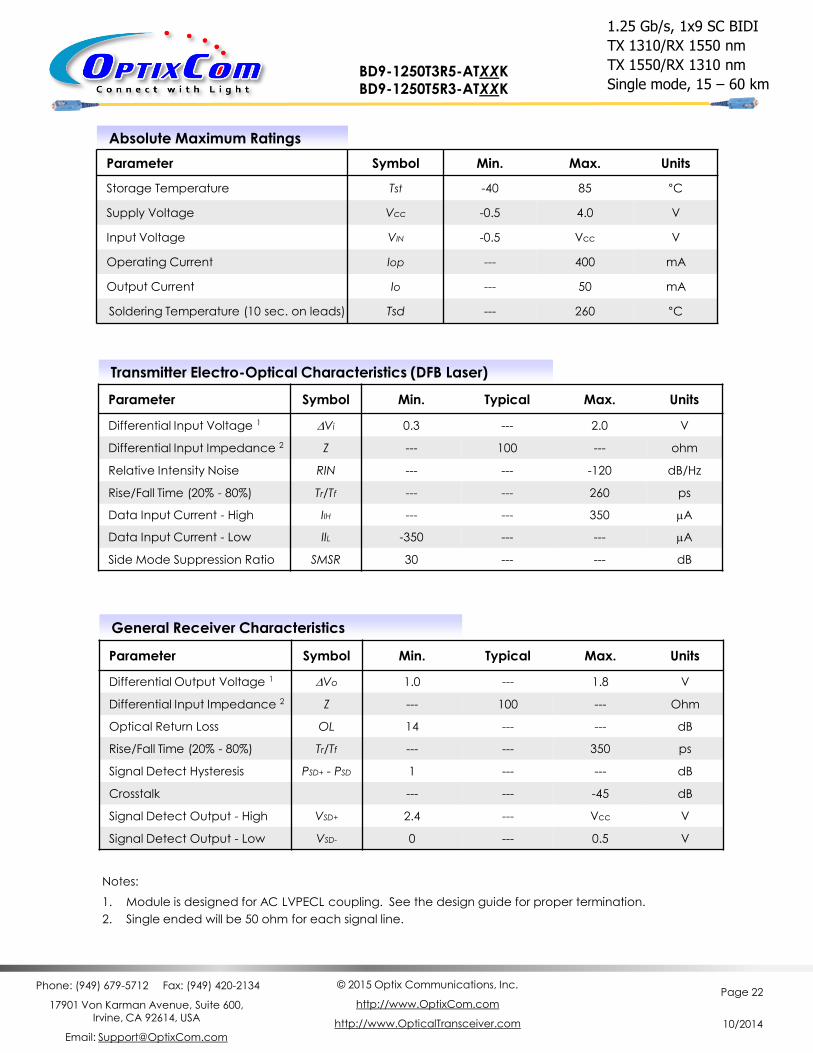
Absolute Maximum Ratings
Parameter Symbol Min. Max. Units
Storage Temperature Tst -40 85 °C
Supply Voltage Vcc -0.5 4.0 V
Input Voltage VIN -0.5 Vcc V
Operating Current Iop --- 400 mA
Output Current Io --- 50 mA
Soldering Temperature (10 sec. on leads) Tsd --- 260 °C
Transmitter Electro-Optical Characteristics (DFB Laser)
Parameter Symbol Min. Typical Max. Units
Differential Input Voltage 1 DVi 0.3 --- 2.0 V
Differential Input Impedance 2 Z --- 100 --- ohm
Relative Intensity Noise RIN --- --- -120 dB/Hz
Rise/Fall Time (20% - 80%) Tr/Tf --- --- 260 ps
Data Input Current - High IIH --- --- 350 mA
Data Input Current - Low IIL -350 --- --- mA
Side Mode Suppression Ratio SMSR 30 --- --- dB
Notes:
1. Module is designed for AC LVPECL coupling. See the design guide for proper termination.
2. Single ended will be 50 ohm for each signal line.
1.25 Gb/s, 1x9 SC BIDI
TX 1310/RX 1550 nm
TX 1550/RX 1310 nm
Single mode, 15 – 60 km BD9-1250T3R5-ATXXK BD9-1250T5R3-ATXXK
General Receiver Characteristics
Parameter Symbol Min. Typical Max. Units
Differential Output Voltage 1 DVo 1.0 --- 1.8 V
Differential Input Impedance 2 Z --- 100 --- Ohm
Optical Return Loss OL 14 --- --- dB
Rise/Fall Time (20% - 80%) Tr/Tf --- --- 350 ps
Signal Detect Hysteresis PSD+ - PSD 1 --- --- dB
Crosstalk --- --- -45 dB
Signal Detect Output - High VSD+ 2.4 --- Vcc V
Signal Detect Output - Low VSD- 0 --- 0.5 V
Phone: (949) 679-5712 Fax: (949) 420-2134
17901 Von Karman Avenue, Suite 600, Irvine, CA 92614, USA
Email: [email protected]
© 2015 Optix Communications, Inc.
http://www.OptixCom.com
http://www.OpticalTransceiver.com
Page 23
10/2014
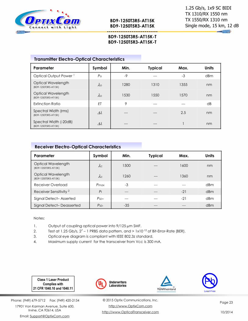
Transmitter Electro-Optical Characteristics
Parameter Symbol Min. Typical Max. Units
Optical Output Power 1 Po -9 --- -3 dBm
Optical Wavelength (BD9-1250T3R5-AT15K)
lo 1280 1310 1355 nm
Optical Wavelength (BD9-1250T5R3-AT15K)
lo 1530 1550 1570 nm
Extinction Ratio ET 9 --- --- dB
Spectral Width (rms) (BD9-1250T3R5-AT15K)
Dl --- --- 2.5 nm
Spectral Width (-20dB) (BD9-1250T5R3-AT15K)
Dl --- --- 1 nm
Receiver Electro-Optical Characteristics
Parameter Symbol Min. Typical Max. Units
Optical Wavelength (BD9-1250T3R5-AT15K)
lc 1500 --- 1600 nm
Optical Wavelength (BD9-1250T5R3-AT15K)
lc 1260 --- 1360 nm
Receiver Overload Pmax -3 --- --- dBm
Receiver Sensitivity 2 PI --- --- -21 dBm
Signal Detect– Asserted PSD+ --- --- -21 dBm
Signal Detect– Deasserted PSD- -35 --- --- dBm
Notes:
1. Output of coupling optical power into 9/125 mm SMF.
2. Test at 1.25 Gb/s, 27 – 1 PRBS data pattern, and > 1x10-12 of Bit-Error-Rate (BER).
3. Optical eye diagram is compliant with IEEE 802.3z standard.
4. Maximum supply current for the transceiver from Vcc is 300 mA.
1.25 Gb/s, 1x9 SC BIDI
TX 1310/RX 1550 nm
TX 1550/RX 1310 nm
Single mode, 15 km, 12 dB
Class 1 Laser Product
Complies with
21 CFR 1040.10 and 1040.11
Pb
Lead-Free
BD9-1250T3R5-AT15K BD9-1250T5R3-AT15K
--------------------------- BD9-1250T3R5-AT15K-T BD9-1250T5R3-AT15K-T
Phone: (949) 679-5712 Fax: (949) 420-2134
17901 Von Karman Avenue, Suite 600, Irvine, CA 92614, USA
Email: [email protected]
© 2015 Optix Communications, Inc.
http://www.OptixCom.com
http://www.OpticalTransceiver.com
Page 24
10/2014
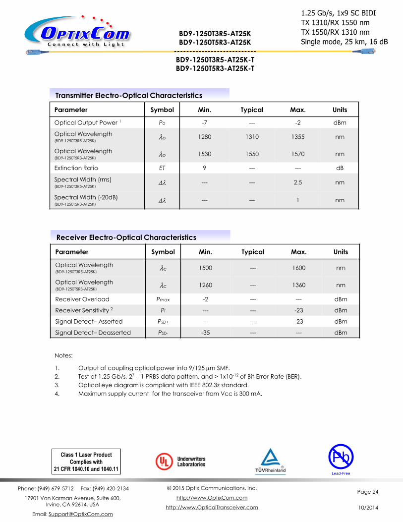
Transmitter Electro-Optical Characteristics
Parameter Symbol Min. Typical Max. Units
Optical Output Power 1 Po -7 --- -2 dBm
Optical Wavelength (BD9-1250T3R5-AT25K)
lo 1280 1310 1355 nm
Optical Wavelength (BD9-1250T5R3-AT25K)
lo 1530 1550 1570 nm
Extinction Ratio ET 9 --- --- dB
Spectral Width (rms) (BD9-1250T3R5-AT25K)
Dl --- --- 2.5 nm
Spectral Width (-20dB) (BD9-1250T5R3-AT25K)
Dl --- --- 1 nm
Receiver Electro-Optical Characteristics
Parameter Symbol Min. Typical Max. Units
Optical Wavelength (BD9-1250T3R5-AT25K)
lc 1500 --- 1600 nm
Optical Wavelength (BD9-1250T5R3-AT25K)
lc 1260 --- 1360 nm
Receiver Overload Pmax -2 --- --- dBm
Receiver Sensitivity 2 PI --- --- -23 dBm
Signal Detect– Asserted PSD+ --- --- -23 dBm
Signal Detect– Deasserted PSD- -35 --- --- dBm
Notes:
1. Output of coupling optical power into 9/125 mm SMF.
2. Test at 1.25 Gb/s, 27 – 1 PRBS data pattern, and > 1x10-12 of Bit-Error-Rate (BER).
3. Optical eye diagram is compliant with IEEE 802.3z standard.
4. Maximum supply current for the transceiver from Vcc is 300 mA.
1.25 Gb/s, 1x9 SC BIDI
TX 1310/RX 1550 nm
TX 1550/RX 1310 nm
Single mode, 25 km, 16 dB
Class 1 Laser Product
Complies with
21 CFR 1040.10 and 1040.11
Pb
Lead-Free
BD9-1250T3R5-AT25K BD9-1250T5R3-AT25K
--------------------------- BD9-1250T3R5-AT25K-T BD9-1250T5R3-AT25K-T
Phone: (949) 679-5712 Fax: (949) 420-2134
17901 Von Karman Avenue, Suite 600, Irvine, CA 92614, USA
Email: [email protected]
© 2015 Optix Communications, Inc.
http://www.OptixCom.com
http://www.OpticalTransceiver.com
Page 25
10/2014
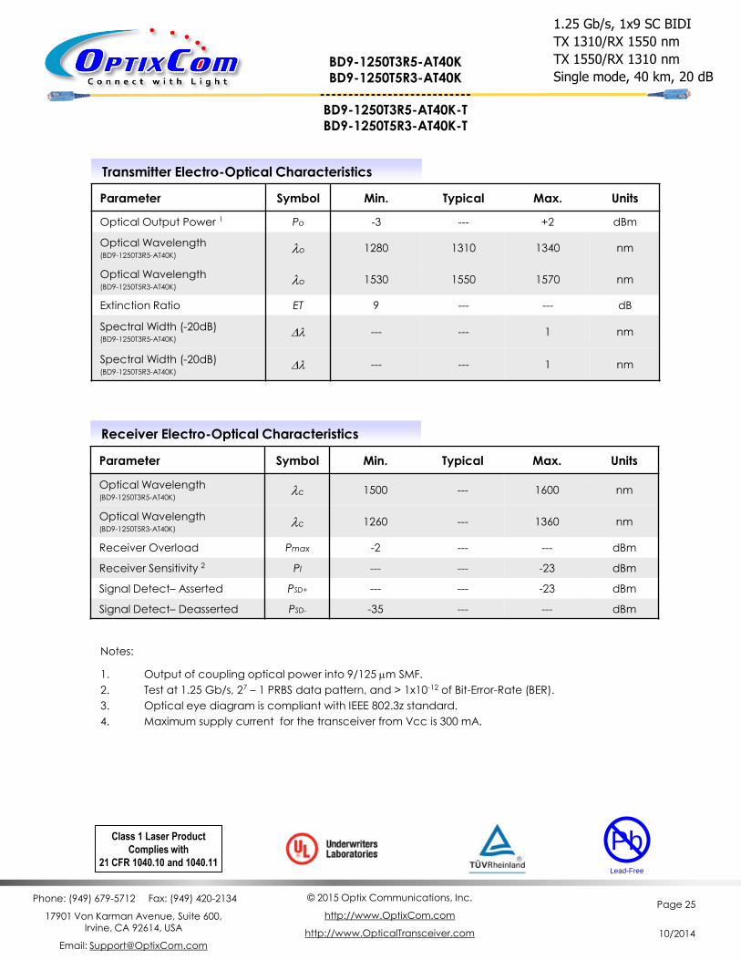
Transmitter Electro-Optical Characteristics
Parameter Symbol Min. Typical Max. Units
Optical Output Power 1 Po -3 --- +2 dBm
Optical Wavelength (BD9-1250T3R5-AT40K)
lo 1280 1310 1340 nm
Optical Wavelength (BD9-1250T5R3-AT40K)
lo 1530 1550 1570 nm
Extinction Ratio ET 9 --- --- dB
Spectral Width (-20dB) (BD9-1250T3R5-AT40K)
Dl --- --- 1 nm
Spectral Width (-20dB) (BD9-1250T5R3-AT40K)
Dl --- --- 1 nm
Receiver Electro-Optical Characteristics
Parameter Symbol Min. Typical Max. Units
Optical Wavelength (BD9-1250T3R5-AT40K)
lc 1500 --- 1600 nm
Optical Wavelength (BD9-1250T5R3-AT40K)
lc 1260 --- 1360 nm
Receiver Overload Pmax -2 --- --- dBm
Receiver Sensitivity 2 PI --- --- -23 dBm
Signal Detect– Asserted PSD+ --- --- -23 dBm
Signal Detect– Deasserted PSD- -35 --- --- dBm
Notes:
1. Output of coupling optical power into 9/125 mm SMF.
2. Test at 1.25 Gb/s, 27 – 1 PRBS data pattern, and > 1x10-12 of Bit-Error-Rate (BER).
3. Optical eye diagram is compliant with IEEE 802.3z standard.
4. Maximum supply current for the transceiver from Vcc is 300 mA.
1.25 Gb/s, 1x9 SC BIDI
TX 1310/RX 1550 nm
TX 1550/RX 1310 nm
Single mode, 40 km, 20 dB
Class 1 Laser Product
Complies with
21 CFR 1040.10 and 1040.11
Pb
Lead-Free
BD9-1250T3R5-AT40K BD9-1250T5R3-AT40K
--------------------------- BD9-1250T3R5-AT40K-T BD9-1250T5R3-AT40K-T
Phone: (949) 679-5712 Fax: (949) 420-2134
17901 Von Karman Avenue, Suite 600, Irvine, CA 92614, USA
Email: [email protected]
© 2015 Optix Communications, Inc.
http://www.OptixCom.com
http://www.OpticalTransceiver.com
Page 26
10/2014
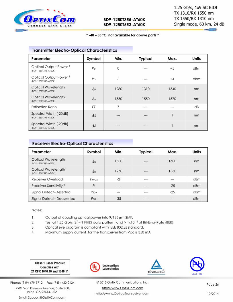
Transmitter Electro-Optical Characteristics
Parameter Symbol Min. Typical Max. Units
Optical Output Power 1
(BD9-1250T3R5-AT60K) Po 0 --- +5 dBm
Optical Output Power 1
(BD9-1250T5R3-AT60K) Po -1 --- +4 dBm
Optical Wavelength (BD9-1250T3R5-AT60K)
lo 1280 1310 1340 nm
Optical Wavelength (BD9-1250T5R3-AT60K)
lo 1530 1550 1570 nm
Extinction Ratio ET 7 --- --- dB
Spectral Width (-20dB) (BD9-1250T3R5-AT60K)
Dl --- --- 1 nm
Spectral Width (-20dB) (BD9-1250T5R3-AT60K)
Dl --- --- 1 nm
Receiver Electro-Optical Characteristics
Parameter Symbol Min. Typical Max. Units
Optical Wavelength (BD9-1250T3R5-AT60K)
lc 1500 --- 1600 nm
Optical Wavelength (BD9-1250T5R3-AT60K)
lc 1260 --- 1360 nm
Receiver Overload Pmax -2 --- --- dBm
Receiver Sensitivity 2 PI --- --- -25 dBm
Signal Detect– Asserted PSD+ --- --- -25 dBm
Signal Detect– Deasserted PSD- -35 --- --- dBm
Notes:
1. Output of coupling optical power into 9/125 mm SMF.
2. Test at 1.25 Gb/s, 27 – 1 PRBS data pattern, and > 1x10-12 of Bit-Error-Rate (BER).
3. Optical eye diagram is compliant with IEEE 802.3z standard.
4. Maximum supply current for the transceiver from Vcc is 350 mA.
1.25 Gb/s, 1x9 SC BIDI
TX 1310/RX 1550 nm
TX 1550/RX 1310 nm
Single mode, 60 km, 24 dB
Class 1 Laser Product
Complies with
21 CFR 1040.10 and 1040.11
Pb
Lead-Free
* -40 – 85 °C not available for above parts *
BD9-1250T3R5-AT60K BD9-1250T5R3-AT60K
---------------------------
Phone: (949) 679-5712 Fax: (949) 420-2134
17901 Von Karman Avenue, Suite 600, Irvine, CA 92614, USA
Email: [email protected]
© 2015 Optix Communications, Inc.
http://www.OptixCom.com
http://www.OpticalTransceiver.com
Page 27
10/2014
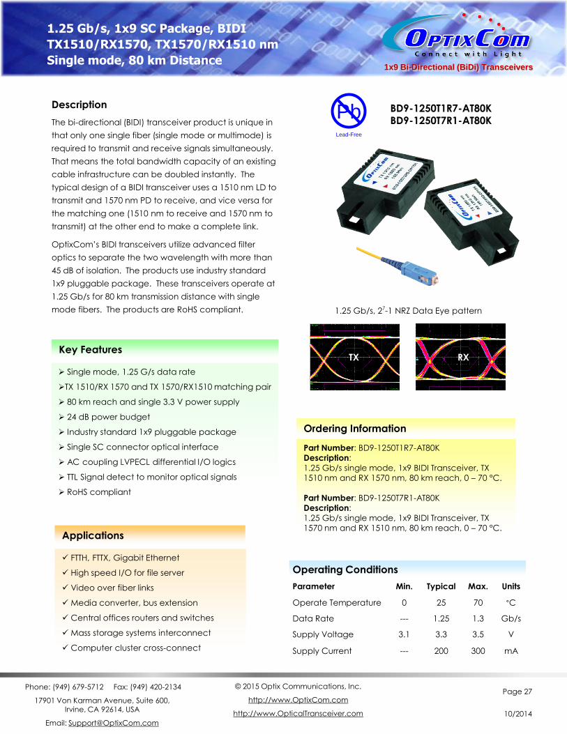
1x9 Bi-Directional (BiDi) Transceivers
Description
The bi-directional (BIDI) transceiver product is unique in
that only one single fiber (single mode or multimode) is
required to transmit and receive signals simultaneously.
That means the total bandwidth capacity of an existing
cable infrastructure can be doubled instantly. The
typical design of a BIDI transceiver uses a 1510 nm LD to
transmit and 1570 nm PD to receive, and vice versa for
the matching one (1510 nm to receive and 1570 nm to
transmit) at the other end to make a complete link.
OptixCom’s BIDI transceivers utilize advanced filter
optics to separate the two wavelength with more than
45 dB of isolation. The products use industry standard
1x9 pluggable package. These transceivers operate at
1.25 Gb/s for 80 km transmission distance with single
mode fibers. The products are RoHS compliant.
Key Features
Single mode, 1.25 G/s data rate
TX 1510/RX 1570 and TX 1570/RX1510 matching pair
80 km reach and single 3.3 V power supply
24 dB power budget
Industry standard 1x9 pluggable package
Single SC connector optical interface
AC coupling LVPECL differential I/O logics
TTL Signal detect to monitor optical signals
RoHS compliant
BD9-1250T1R7-AT80K BD9-1250T7R1-AT80K
Ordering Information
Part Number: BD9-1250T1R7-AT80K
Description:
1.25 Gb/s single mode, 1x9 BIDI Transceiver, TX
1510 nm and RX 1570 nm, 80 km reach, 0 – 70 °C.
Part Number: BD9-1250T7R1-AT80K
Description:
1.25 Gb/s single mode, 1x9 BIDI Transceiver, TX
1570 nm and RX 1510 nm, 80 km reach, 0 – 70 °C.
1.25 Gb/s, 1x9 SC Package, BIDI
TX1510/RX1570, TX1570/RX1510 nm
Single mode, 80 km Distance
Pb
Lead-Free
TX RX
Applications
FTTH, FTTX, Gigabit Ethernet
High speed I/O for file server
Video over fiber links
Media converter, bus extension
Central offices routers and switches
Mass storage systems interconnect
Computer cluster cross-connect
1.25 Gb/s, 27-1 NRZ Data Eye pattern
Operating Conditions
Parameter Min. Typical Max. Units
Operate Temperature 0 25 70 °C
Data Rate --- 1.25 1.3 Gb/s
Supply Voltage 3.1 3.3 3.5 V
Supply Current --- 200 300 mA
Phone: (949) 679-5712 Fax: (949) 420-2134
17901 Von Karman Avenue, Suite 600, Irvine, CA 92614, USA
Email: [email protected]
© 2015 Optix Communications, Inc.
http://www.OptixCom.com
http://www.OpticalTransceiver.com
Page 28
10/2014
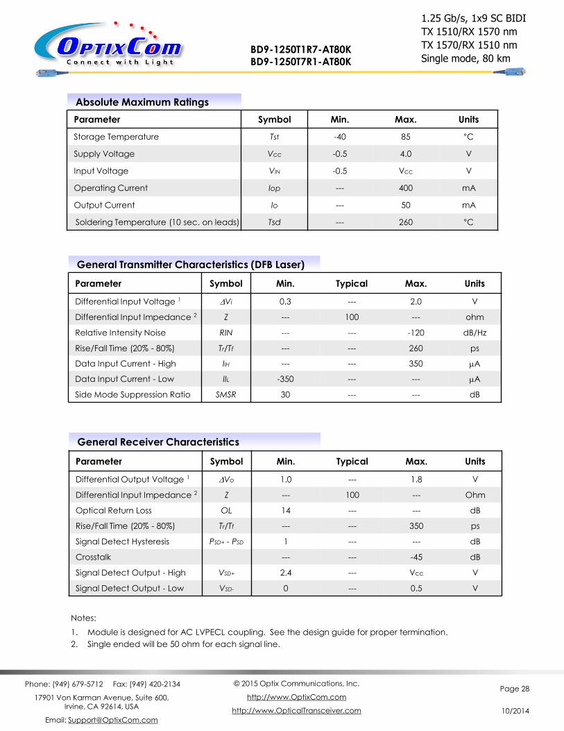
Absolute Maximum Ratings
Parameter Symbol Min. Max. Units
Storage Temperature Tst -40 85 °C
Supply Voltage Vcc -0.5 4.0 V
Input Voltage VIN -0.5 Vcc V
Operating Current Iop --- 400 mA
Output Current Io --- 50 mA
Soldering Temperature (10 sec. on leads) Tsd --- 260 °C
General Transmitter Characteristics (DFB Laser)
Parameter Symbol Min. Typical Max. Units
Differential Input Voltage 1 DVi 0.3 --- 2.0 V
Differential Input Impedance 2 Z --- 100 --- ohm
Relative Intensity Noise RIN --- --- -120 dB/Hz
Rise/Fall Time (20% - 80%) Tr/Tf --- --- 260 ps
Data Input Current - High IIH --- --- 350 mA
Data Input Current - Low IIL -350 --- --- mA
Side Mode Suppression Ratio SMSR 30 --- --- dB
Notes:
1. Module is designed for AC LVPECL coupling. See the design guide for proper termination.
2. Single ended will be 50 ohm for each signal line.
1.25 Gb/s, 1x9 SC BIDI
TX 1510/RX 1570 nm
TX 1570/RX 1510 nm
Single mode, 80 km BD9-1250T1R7-AT80K BD9-1250T7R1-AT80K
General Receiver Characteristics
Parameter Symbol Min. Typical Max. Units
Differential Output Voltage 1 DVo 1.0 --- 1.8 V
Differential Input Impedance 2 Z --- 100 --- Ohm
Optical Return Loss OL 14 --- --- dB
Rise/Fall Time (20% - 80%) Tr/Tf --- --- 350 ps
Signal Detect Hysteresis PSD+ - PSD 1 --- --- dB
Crosstalk --- --- -45 dB
Signal Detect Output - High VSD+ 2.4 --- Vcc V
Signal Detect Output - Low VSD- 0 --- 0.5 V
Phone: (949) 679-5712 Fax: (949) 420-2134
17901 Von Karman Avenue, Suite 600, Irvine, CA 92614, USA
Email: [email protected]
© 2015 Optix Communications, Inc.
http://www.OptixCom.com
http://www.OpticalTransceiver.com
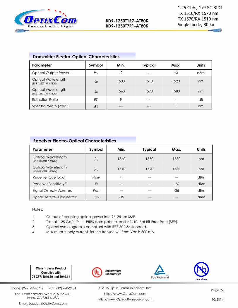
Page 29
10/2014
Transmitter Electro-Optical Characteristics
Parameter Symbol Min. Typical Max. Units
Optical Output Power 1 Po -2 --- +3 dBm
Optical Wavelength (BD9-1250T1R7-AT80K)
lo 1500 1510 1520 nm
Optical Wavelength (BD9-1250T7R1-AT80K)
lo 1560 1570 1580 nm
Extinction Ratio ET 9 --- --- dB
Spectral Width (-20dB) Dl --- --- 1 nm
Receiver Electro-Optical Characteristics
Parameter Symbol Min. Typical Max. Units
Optical Wavelength (BD9-1250T1R7-AT80K)
lc 1560 1570 1580 nm
Optical Wavelength (BD9-1250T7R1-AT80K)
lc 1510 1520 1530 nm
Receiver Overload Pmax -1 --- --- dBm
Receiver Sensitivity 2 PI --- --- -26 dBm
Signal Detect– Asserted PSD+ --- --- -26 dBm
Signal Detect– Deasserted PSD- -35 --- --- dBm
Notes:
1. Output of coupling optical power into 9/125 mm SMF.
2. Test at 1.25 Gb/s, 27 – 1 PRBS data pattern, and > 1x10-12 of Bit-Error-Rate (BER).
3. Optical eye diagram is compliant with IEEE 802.3z standard.
4. Maximum supply current for the transceiver from Vcc is 300 mA.
Class 1 Laser Product
Complies with
21 CFR 1040.10 and 1040.11
Pb
Lead-Free
1.25 Gb/s, 1x9 SC BIDI
TX 1510/RX 1570 nm
TX 1570/RX 1510 nm
Single mode, 80 km BD9-1250T1R7-AT80K BD9-1250T7R1-AT80K