Embed Size (px)
Citation preview

1HMC VLSI Lab
Very High Radix Montgomery Very High Radix Montgomery MultiplicationMultiplicationDavid Harris, Kyle Kelley and Ted Jiang
Harvey Mudd College
Claremont, CA
Supported by Intel Circuit Research Labs

2HMC VLSI Lab
OutlineOutline• RSA Encryption• Montgomery Multiplication• Radix 2 Implementations
– Tenca-Koç Radix 2– Improved Radix 2
• Very High Radix Implementations– Very High Radix– Parallel Very High Radix– Quotient Pipelining
• Results• Future Work

3HMC VLSI Lab
RSA EncryptionRSA Encryption
• Most widely used public key system.– Good for encryption and signatures.– Invented by Rivest, Shamir, Adleman (1978)
• Public e and private d keys are long #s– n = 256-2048+ bits– Satisfy xde mod M = x for all x– Finding d from e is as hard as factoring M
• Encryption: B = Ae mod M• Decryption: C = Bd mod M = Aed = A

4HMC VLSI Lab
RSA DerivationRSA Derivation
• Choose two large random primes p, q• M = pq• Totient: = (p-1)(q-1)• Public key e
– e is coprime to
• Private key d – such that de = 1 mod
• Then xed mod M = x – According to Fermat’s Little Theorem

5HMC VLSI Lab
Cryptographic AlgorithmsCryptographic Algorithms
• DES, AES– Symmetric key algorithms
• Require exchange of secret key
– Computationally efficient
• RSA, ECC– Public key algorithms
• No key exchange needed (e.g. ecommerce)
– Computationally expensive– Use public key to exchange symmetric
key
6HMC VLSI Lab
Modular ExponentiationModular Exponentiation
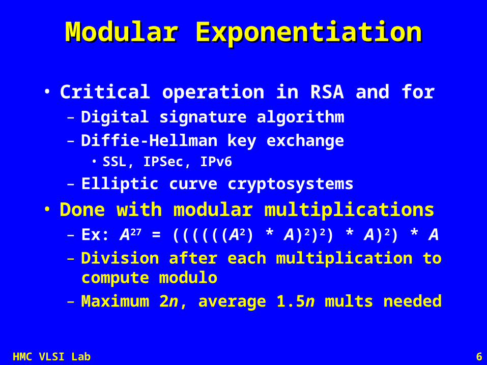
• Critical operation in RSA and for– Digital signature algorithm– Diffie-Hellman key exchange
• SSL, IPSec, IPv6
– Elliptic curve cryptosystems
• Done with modular multiplications– Ex: A27 = ((((((A2) * A)2)2) * A)2) * A– Division after each multiplication to compute
modulo– Maximum 2n, average 1.5n mults needed

7HMC VLSI Lab
Binary Extension FieldsBinary Extension Fields
• Building blocks are polynomials in x– Operations performed modulo some
irreducible polynomial f(x) of degree n– Arithmetic done modulo 2– Called GF(2n)
• Example: GF(23)– 0, 1, x, x+1, x2, x2+1, x2+x, x2+x+1
• Computation is the same as GF(p)– Except that no carries are propagated

8HMC VLSI Lab
Montgomery MultiplicationMontgomery Multiplication
• Faster way to do modular exponentation– Operate on Montgomery residues– Division becomes a simple shift– Requires conversion to and from
residues only once per exponentiation

9HMC VLSI Lab
Montgomery ResiduesMontgomery Residues
• Let the modulus M be an odd n-bit integer– 2n-1 < M < 2n
• Define R = 2n
• Define the M-residue of an integer A < M as– AA = AR mod M
• There is a one-to-one correspondence between integers and M-residues for
0 < A < M-1

10HMC VLSI Lab
Montgomery MultiplicatonMontgomery Multiplicaton
• DefineZ = MM(X, Y) = X Y R-1 mod M
• Where R-1 is the inverse of R mod M: R-1R = 1 (mod M)
• Montgomery Mult finds residue of Z = XY mod MZ = X Y R-1 mod M
= (XR) (YR) R-1 mod M
= XYR mod M
= ZR mod M

11HMC VLSI Lab
Montgomery ReductionMontgomery Reduction
Precompute M’ satisfying RR-1 – MM’ = 1
Convert mult and mod to 3 mult and shift
Multiply: Z = X × Y
Reduce: reduce = Z × M’ mod R
Z = [Z + reduce × M] / R
Normalize: if Z ≥ M then Z = Z – M
Why is Z + Reduce × M divisible by R?
Mult
Mult
Mult Shift for R-1
Drop bits
12HMC VLSI Lab
Reduction ProofReduction Proof
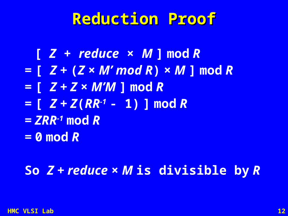
[ Z + reduce × M ] mod R= [ Z + (Z × M’ mod R) × M ] mod R= [ Z + Z × M’M ] mod R= [ Z + Z(RR-1 - 1) ] mod R= ZRR-1 mod R= 0 mod R
So Z + reduce × M is divisible by R

13HMC VLSI Lab
More Comments on M’More Comments on M’
• RR-1 – MM’ = 1 – Implies M’ -M-1 mod R– M’ is odd
• M’ is precomputed from M using the extended Euclidian algorithm– M is held constant over many mults
• Only least significant v bits of M’ are needed when computing in radix 2v
– Dusse & Kaliski, Eurocrypt ’90s

14HMC VLSI Lab
CPU Crypto AcceleratorsCPU Crypto Accelerators
• VIA Esther Padlock Hardware Security– Montgomery Multiplier < 0.5 mm2 die area– Accessed by x86 instruction– 256b - 32Kb keys in 128 bit granularity– Also supports AES
• SmartMIPS Smart Card Extensions– RSA, ECC, AES applications– GF(2n) multiply, MAC instructions– Carry propagation for multiword adds– AES permutations and rotations
• Intel LaGrande Technology– Trusted computing

15HMC VLSI Lab
Embedded Crypto AcceleratorsEmbedded Crypto Accelerators
3COM Router 5000 Series Encryption Accelerator
IBM PCI SSL Cryptography Accelerator

16HMC VLSI Lab
Radix 2 AlgorithmRadix 2 Algorithm
• In radix 2, process one bit of X per step– Reduction becomes trivial because M’ mod 2 = 1– Two multiplies and one shift per step
Z = 0for i = 0 to n-1
Z = Z + Xi × Y
reduce = Z0 trivial
Z = Z + reduce × M make Z divisible by 2
Z = Z/2if Z ≥ M then Z = Z – M final Mod M
Z = X × Y
reduce = Z × M’ mod R
Z = [Z + reduce × M] / R
if Z ≥ M then Z = Z – M

17HMC VLSI Lab
Final ModuloFinal Modulo
• Result before last step in range – 0 Z < 2M– Reducing Z-M at the end is a hassle
• Allow 0 X, Y < 2M to avoid reduction– Then if R > 4M, 0 Z < 2M– Hence add two bits to R to avoid
subtraction at end of each step
Walter, Electronic Letters ’99

18HMC VLSI Lab
ConversionConversion
• Conversion of integers to/from Montgomery residues takes one MM operation (if r2 mod M is precomputed and saved):
• Modular exponentiation takes two conversion steps and ~2n multiplication steps.
xMrxrMrxxMMx
MxrMrxrrxMMx
mod 1 mod1)1,(
mod mod),(11
122

19HMC VLSI Lab
Reconfigurable HardwareReconfigurable Hardware
• Building hardwired n-bit unit is limiting– Slow for large n– Not scalable to different n
• Better to design for w-bit words– Break n-bit operand into e w-bit words
• e = n/w
– This is called scalable
• Also handle both GF(p) and GF(2n)– Requires conditionally killing carries– Called unified

20HMC VLSI Lab
Tenca-Koç Montgomery MultiplierTenca-Koç Montgomery Multiplier
Z = 0
for i = 0 to n-1
(Ca, Z0) = Z0 + Xi × Y0
reduce = Z0
(Cb, Z0) = Z0 + reduce × M0
for j = 1 to e
(Ca,Zj) = Zj + Ca + Xi × Yj
(Cb,Zj) = Zj + Cb + reduce × Mj
Zj-1 = (Zj0, Zj-1
w-1:1)
M = (M(e-1), …, M1, M0), Y = (Y(e-1), …, Y1, Y0), Z = (Z(e-1), …, Z1, Z0), X = (Xn-1, …, X1, X0)
Tenca, Koçç, Trans. Computers, 2003
21HMC VLSI Lab
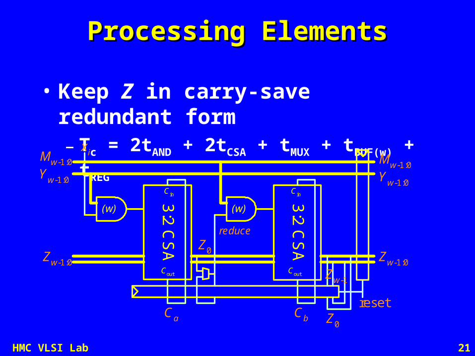
Processing ElementsProcessing Elements
• Keep Z in carry-save redundant form– Tc = 2tAND + 2tCSA + tMUX + tBUF(w) + tREG
3:2C
SA
3:2C
SA
(w)
Cin
Cb
xi
Zw-1:0
Yw-1:0
Mw-1:0
Ca
Cout
Cin
Cout
reset
(w)
Z0
Zw-1
Z0
Zw-1:0
Mw-1:0
Yw-1:0
reduce

22HMC VLSI Lab
ParallelismParallelism
• Two dimensions of parallelism:– Width of processing element w– Number of pipelined PEs p
• Multiply takes k = n/p kernel cycles
FIFO
0YM
Mem
X Mem
PE1 PE2 PE3 PE p
SequenceControl
Result
Z
MY
xKernel
Z’

23HMC VLSI Lab
Pipeline TimingPipeline Timing
Ker
nel
Cyc
le 1
Case I: e > 2p-1e = 4, p = 2
Case II: e < 2p-1e = 4, p = 4
tim
e
spacePE1 PE2
1 x0
x1
x0
x1
x0
x1
x0
x1
x3
x3
x3
x3
x2
x2
x2
x2
2
3
4
5
6
7
8
9
10
11
12
13
Ker
nel
Cyc
le 2
PE1 PE2 PE3 PE4
KernelStall
MYw-1:0Zw-2:-1
MY2w-1:wZ2w-2:w-1
MY3w-1:2wZ3w-2:2w-1
MY4w-1:3wZ4w-2:3w-1
MYw-1:0Zw-2:-1
MY2w-1:wZ2w-2:w-1
MY3w-1:2wZ3w-2:2w-1
MY4w-1:3wZ4w-2:3w-1
MYw-1:0Zw-2:-1
MY2w-1:wZ2w-2:w-1
MY3w-1:2wZ3w-2:2w-1
MY4w-1:3wZ4w-2:3w-1
MYw-1:0Zw-2:-1
MY2w-1:wZ2w-2:w-1
MY3w-1:2wZ3w-2:2w-1
MY4w-1:3wZ4w-2:3w-1
x1
MY5w-1:4wZ5w-2:4w-1
x0
MY5w-1:4wZ5w-2:4w-1
x3
MY5w-1:4wZ5w-2:4w-1
x2
MY5w-1:4wZ5w-2:4w-1
x0
x0
x0
x0
MYw-1:0Zw-2:-1
MY2w-1:wZ2w-2:w-1
MY3w-1:2wZ3w-2:2w-1
MY4w-1:3wZ4w-2:3w-1
x0
MY5w-1:4wZ5w-2:4w-1
MYw-1:0Zw-2:-1
MY2w-1:wZ2w-2:w-1
MY3w-1:2wZ3w-2:2w-1
MY4w-1:3wZ4w-2:3w-1
MY5w-1:4wZ5w-2:4w-1
MYw-1:0Zw-2:-1
MY2w-1:wZ2w-2:w-1
MY3w-1:2wZ3w-2:2w-1
MY4w-1:3wZ4w-2:3w-1
MY5w-1:4wZ5w-2:4w-1
MYw-1:0Zw-2:-1
MY2w-1:wZ2w-2:w-1
MY3w-1:2wZ3w-2:2w-1
MY4w-1:3wZ4w-2:3w-1
MY5w-1:4wZ5w-2:4w-1
x1
x2
x3
x1
x2
x3
x1
x2
x3
x1
x2
x3
x1
x2
x3
x0
x0
x0
x0
MYw-1:0Zw-2:-1
MY2w-1:wZ2w-2:w-1
MY3w-1:2wZ3w-2:2w-1
MY4w-1:3wZ4w-2:3w-1
x0
MY5w-1:4wZ5w-2:4w-1
MYw-1:0Zw-2:-1
MY2w-1:wZ2w-2:w-1
MY3w-1:2wZ3w-2:2w-1
MY4w-1:3wZ4w-2:3w-1
MY5w-1:4wZ5w-2:4w-1
MYw-1:0Zw-2:-1
MY2w-1:wZ2w-2:w-1
MY3w-1:2wZ3w-2:2w-1
MY4w-1:3wZ4w-2:3w-1
MY5w-1:4wZ5w-2:4w-1
MYw-1:0Zw-2:-1
MY2w-1:wZ2w-2:w-1
MY3w-1:2wZ3w-2:2w-1
MY4w-1:3wZ4w-2:3w-1
MY5w-1:4wZ5w-2:4w-1
x1
x2
x3
x1
x2
x3
x1
x2
x3
x1
x2
x3
x1
x2
x3
Ker
nel
Cyc
le 1
Ker
nel
Cyc
le 2
14
15
16
17
18
19
20
24HMC VLSI Lab
QueueQueue
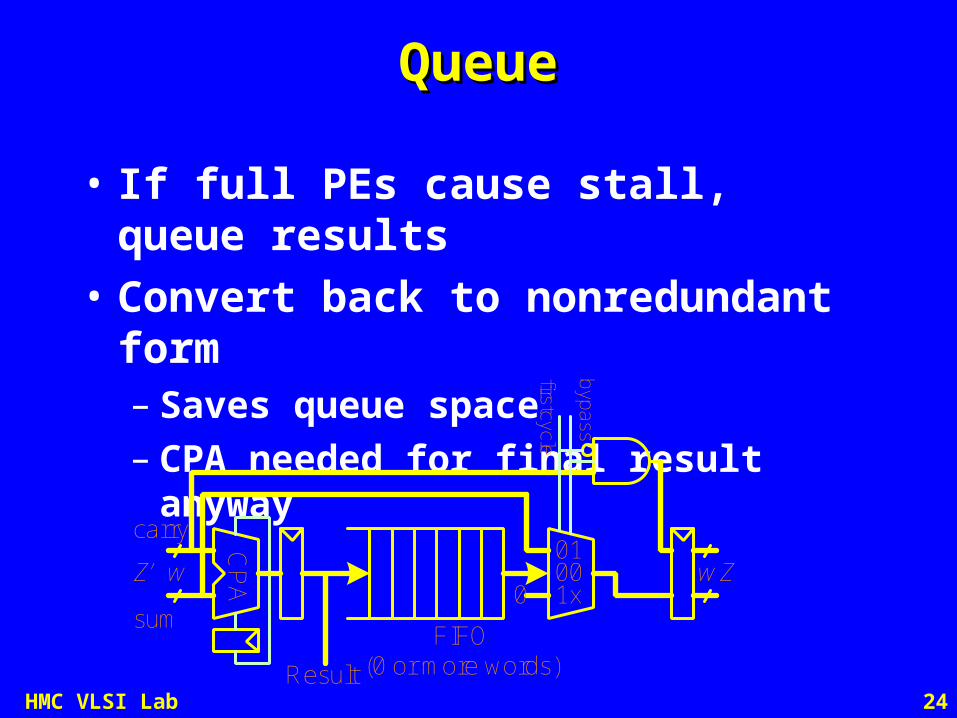
• If full PEs cause stall, queue results
• Convert back to nonredundant form– Saves queue space– CPA needed for final result anyway
Z’ Z
Result
FIFO(0 or more words)
firstcycle
byp
ass
1x0
0100w w
sum
carry CP
A

25HMC VLSI Lab
Improved DesignImproved Design
• Don’t wait two cycles for MSB• Kick off dependent operation right away
on the available bits• Take extra cycle(s) at the end to handle
the extra bits• For p processing elements, cycle count
reduces from 2p to p + (p/w)
Harris, Krishnamurthy, Anders, Mathew, Hsu, Arith 2005.

26HMC VLSI Lab
Improved PEImproved PE
• Left-shift M and Y – Rather than right-shift Z
• Same amount of hardware
3:2C
SA
3:2C
SA
(w)Cin
Cb
xi
reduce
Zw-1:0
Mw-1:0Yw-1:0
M-1
Zw-2:-1
Yw-2:-1
Mw-2:-1
Mw-1
Ca
Cout
Cin
Cout
reset
(w)
Yw-1
Y-1
Z0

27HMC VLSI Lab
Pipeline TimingPipeline Timing
Ker
nel
Cyc
le 1
Case I: e > p+1e = 4, p = 2
Case II: e < p+1e = 4, p = 4
tim
espace
PE1 PE2
1 MYw-1:0Zw-2:-1
x0
MYw-2:-1Zw-3:-2
x1MY2w-1:wZ2w-2:w-1
x0
MY2w-2:w-1Z2w-3:w-2
x1MY3w-1:2wZ3w-2:2w-1
x0
MY3w-2:2w-1Z3w-3:2w-2
x1MY4w-1:3wZ4w-2:3w-1
x0
MY4w-2:3w-1Z4w-3:3w-2
x1
x3
x3
x3
x3
x2
x2
x2
x2
2
3
4
5
6
7
8
9
10
11
12
13
Ker
nel
Cyc
le 2
Ker
nel
Cyc
le 1
PE1 PE2x0
x1x0
x1x0
x1x0
x1
MYw-3:-2Zw-4:-3
x2
MY2w-3:w-2Z2w-4:w-3
x2
MY3w-3:2w-2Z3w-4:2w-3
x2
MY4w-3:3w-2Z4w-4:3w-3
x2
MYw-4:-3Zw-5:-4
x3
MY2w-4:w-3Z2w-5:w-4
x3
MY3w-4:2w-3Z3w-5:2w-4
x3
MY4w-4:3w-3Z4w-5:3w-4
x3
PE3 PE4
Ker
nel
Cyc
le 2 x4
x5x4
x4
x4
x6
x7
Kernel StallMYw-1:0Zw-2:-1
MYw-2:-1Zw-3:-2
MY2w-1:wZ2w-2:w-1
MY2w-2:w-1Z2w-3:w-2
MY3w-1:2wZ3w-2:2w-1
MY3w-2:2w-1Z3w-3:2w-2
MY4w-1:3wZ4w-2:3w-1
MY4w-2:3w-1Z4w-3:3w-2
MYw-1:0Zw-2:-1
MYw-2:-1Zw-3:-2
MY2w-1:wZ2w-2:w-1
MY2w-2:w-1Z2w-3:w-2
MY3w-1:2wZ3w-2:2w-1
MY3w-2:2w-1Z3w-3:2w-2
MY4w-1:3wZ4w-2:3w-1
MY4w-2:3w-1Z4w-3:3w-2
MYw-1:0Zw-2:-1
MYw-2:-1Zw-3:-2
MY2w-1:wZ2w-2:w-1
MY2w-2:w-1Z2w-3:w-2
MY3w-1:2wZ3w-2:2w-1
MY3w-2:2w-1Z3w-3:2w-2
MY4w-1:3wZ4w-2:3w-1
MY4w-2:3w-1Z4w-3:3w-2
MYw-3:-2Zw-4:-3
MY2w-3:w-2Z2w-4:w-3
MY3w-3:2w-2Z3w-4:2w-3
MY4w-3:3w-2Z4w-4:3w-3
MYw-4:-3Zw-5:-4
MY3w-4:2w-3Z3w-5:2w-4
MY4w-4:3w-3Z4w-5:3w-4
MY2w-4:w-3Z2w-5:w-4
x5
x6
x7
x5
x6
x7
x5
x6
x7
MY5w-1:4wZ5w-2:4w-1
x0
MY5w-2:4w-1Z5w-3:4w-2
x1
14
MY5w-1:4wZ5w-2:4w-1
x2
MY5w-2:4w-1Z5w-3:4w-2
x3
x0
MY5w-3:4w-2Z5w-4:4w-3
x2
MY5w-4:4w-3Z5w-5:4w-4
x3
MY5w-1:4wZ5w-2:4w-1
x1MY5w-2:4w-1Z5w-3:4w-2
x4
MY5w-3:4w-2Z5w-4:4w-3
x6
MY5w-4:4w-3Z5w-5:4w-4
x7
MY5w-1:4wZ5w-2:4w-1
MY5w-2:4w-1Z5w-3:4w-2
x5

28HMC VLSI Lab
LatencyLatency
• Tenca-Koç
k(e+1) + 2(p-1) n > 2pw – w k(2p+1) + e - 2 n 2pw – w
• Improved Design
(k+1)(e+1) + p-2 n > pw k(p+1) + 2e - 1 n pw
29HMC VLSI Lab
BreakBreak

30HMC VLSI Lab
BreakBreak

31HMC VLSI Lab
BreakBreak

32HMC VLSI Lab
Very High RadixVery High Radix
• Handle many bits of X at a time– Radix 2v processes v bits of X
• Only f = n/v outer loop iterations needed• k = n/pv kernel cycles with p PEs
– Hardware changes• w bit AND v w bit multiplier• Right shift by v bits after each step
– Use v w so bits are available to shift
• Cycle time gets longer
– Reduce becomes more complicated• Must drive v lsbs to 0

33HMC VLSI Lab
Very High Radix AlgorithmVery High Radix Algorithm
Z = 0
for i = 0 to f-1
Z = Z + Xi × Y reduce = (M’ × Z) mod 2v reduce bottom v bits
Z = Z + reduce × M
Z = Z / 2v
Z = X × Y
reduce = Z × M’ mod R
Z = [Z + reduce × M] / R

34HMC VLSI Lab
Scalable Very High Radix MMScalable Very High Radix MM
Z = 0
for i = 0 to f-1
(CA, Z0) = Z0 + X0 × Y0
reduce = (M’ × Z0) mod 2v only reduce bottom v bits
(CB, Z0) = Z0 + reduce × M0
for j = 1 to e + (v + 1) / w - 1 (CA, Zj) = Zj + CA + Xi × Yj
(CB, Zj) = Zj + CB + reduce × Mj
Zj-1 = (Zjv-1:0, Zj-1
w-1:v)
2 mul, 1 shift
in inner loop

35HMC VLSI Lab
Very High Radix PEVery High Radix PE
Z
*
X
Y
reduce
M
M'
v
v+w0
1*
1 0CA CB
w
w
v
v v
w+1
w w
v+w
w+1
v+w
YMZ to next PE
Y
first
first to next PE
v+w
w w
vv
v
w-vMAC MAC
upper
low
er
v
Kelley, Harris IWSOC 2005Kelley, Harris IWSOC 2005

36HMC VLSI Lab
Pipeline TimingPipeline Timing
Each MAC is given a full cycle
Tc = tMUL(v,w) + tCPA(v+w) + tmux + tREG
Two MAC columns for each PE
Four cycle latency between PEs:
1) Z0 = Xi × Y0
2) reduce = M’ × Z0 mod 2v
3) Z0 = Z0 + reduce × M0
4) Z1 = Z1 + reduce × M1, shift into Z0
Zw-1:0
reduce
Xv-1:0
Yw-1:0
Zw-1:0
Y2w-1:w
Z2w-1:w
Y3w-1:2w
Z3w-1:2w
Y4w-1:3w
Z4w-1:3w
Y 5w-1:4w
Z5w-1:4w
Y6w-1:5w
Z6w-1:5w
Mw-1:0
Zw-1:0
Y2w-1:w
Z2w-1:w
M3w-1:2w
Z3w-1:2w
M4w-1:3w
Z4w-1:3w
M5w-1:4w
Z5w-1:4w
M6w-1:5w
Z6w-1:5w
Zw-1:0
reduce
X 2v-1:v
Yw-1:0
Zw-1:0
Y2w-1:w
Z2w-1:w
Y3w-1:2w
Z3w-1:2w
Y4w-1:3w
Z4w-1:3w
Y5w-1:4w
Z5w-1:4w
Y6w-1:5w
Z6w-1:5w
Mw-1:0
Zw-1:0
M2w-1:w
Z2w-1:w
M3w-1:2w
Z3w-1:2w
M4w-1:3w
Z4w-1:3w
M5w-1:4w
Z5w-1:4w
M6w-1:5w
Z6w-1:5w
Zw-1:0
reduce
Yw-1:0
Zw-1:0
Y2w-1:w
Z2w-1:w
Y3w-1:2w
Z3w-1:2w
Y4w-1:3w
Z4w-1:3w
Y5w-1:4w
Z5w-1:4w
Y6w-1:5w
Z6w-1:5w
Mw-1:0
Zw-1:0
M2w-1:w
Z2w-1:w
M3w-1:2w
Z3w-1:2w
M4w-1:3w
Z4w-1:3w
M5w-1:4w
Z5w-1:4w
M6w-1:5w
Z6w-1:5w
X3v-1:2v
Zw-1:0
reduce
Yw-1:0
Zw-1:0
Y2w-1:w
Z2w-1:w
Y 3w-1:2w
Z3w-1:2w
Y4w-1:3w
Z4w-1:3w
Y5w-1:4w
Z5w-1:4w
Mw-1:0
Zw-1:0
M2w-1:w
Z2w-1:w
M3w-1:2w
Z3w-1:2w
Yw-1:0
Zw-1:0
Ker
nelS
tall
PE 1 PE 2 PE 3
Ke
rnel
Cyc
le1
Ke
rnel
Cyc
le2
X4v-1:3v
X5v-1:4v
… … … … … …
1
Cycle #
2
3
4
5
6
7
8
9
10
11
12
13
14
15
16
17
18

37HMC VLSI Lab
Very High Radix LatencyVery High Radix Latency
k(e + 3) + 4(p - 1) + 2 n > 4pw – 2w k(4p + 1) + (e - 1) n 4pw – 2w
• Design limited for small n by 4-cycle latency between PEs

38HMC VLSI Lab
Parallel Very High RadixParallel Very High Radix
• Eliminate two of the cycles– Multiplication to compute reduce
• By precomputing M = M’ × M mod R
– Dependency of Z0 on reduce• By prescaling X by 2v so Z0 = 0
• Math proposed by Orup Arith95– But no scalable very high radix HW
~

39HMC VLSI Lab
Improvement 1: Eliminate MultiplyImprovement 1: Eliminate Multiply
Z = 0
for i = 0 to f-1
Z = Z + Xi × Y
Z = Z + Z0 × M M = (M’ mod 2v)M mod R
Z = Z / 2v
M = M’ × M mod R (precompute)
Z = X × Y
Z = [Z + Z × M] / R
Z = X × Y
reduce = Z × M’ mod R
Z = [Z + reduce × M] / R~
~
~
~

40HMC VLSI Lab
Improvement 2: Prescale X by 2Improvement 2: Prescale X by 2vv
Z = 0
for i = 0 to f
Z = Z + 2vXi × Y + Z0 × M
Z = Z / 2v
Z = 0
for i = 0 to f
Z = (Z + Z0 × M) / 2v + Xi × Y
Z = 0
for i = 0 to f-1
Z = Z + Xi × Y
Z = Z + Z0 × M
Z = Z / 2v
~
~
~
Because Z0 is independent of 2vXi
Final result in range 0 Z < 2n+v+1
- avoid final small mod in successive mults by using larger R
One more iteration

41HMC VLSI Lab
Improvement 3: Avoid LSW addImprovement 3: Avoid LSW add
Z = 0
for i = 0 to f
Z = (Z + Z0 × M) / 2v + Xi × Y
Z = 0
for i = 0 to f
reduce = Z0
Z = Z >> v + reduce × M + Xi × Y
~
M + 1M =
~
2v
(Z + Z0 × M) / 2v
= Z >> v + (Z0 × M + Z mod 2v) / 2v
= Z >> v + (Z0 × (M+1)) / 2v
= Z >> v + Z0 × M
~
~
~
M M’M -1 mod 2v
So M + 1 is divisible
~
~

42HMC VLSI Lab
Scalable Parallel Very High RadixScalable Parallel Very High Radix
Z = 0
for i = 0 to f
C = 0
reduce = Z0
for j = 0 to e + v/w (C, Zj) = Zj + C + reduce × Mj
+ Xi × Yj
Zj-1 = (Zjv-1:0, Zj-1
w-1:v)

43HMC VLSI Lab
Parallel Very High Radix PEParallel Very High Radix PE
Kelley, Harris Asilomar 2005Kelley, Harris Asilomar 2005

44HMC VLSI Lab
Pipeline TimingPipeline Timing
Xv-1:0
Yw-1:0
Zw-1:0
Y2w-1:w
Z2w-1:w
Y3w-1:2w
Z3w-1:2w
Y4w-1:3w
Z4w-1:3w
Y5w-1:4w
Z5w-1:4w
Y6w-1:5w
Z6w-1:5w
Yw-1:0
Zw-1:0
Y2w-1:w
Z2w-1:w
Y3w-1:2w
Z3w-1:2w
Y4w-1:3w
Z4w-1:3w
Y5w-1:4w
Z5w-1:4w
Ker
nel S
tall
PE 1 PE 2 PE 3
Ke
rne
l Cyc
le 1
Ke
rne
l Cyc
le 2
X5v-1:4v
… … … …
1
Cycle #
2
3
4
5
6
7
8
9
10
11
12
13
14
15
X2v-1:v
Yw-1:0
Zw-1:0
Y2w-1:w
Z2w-1:w
Y3w-1:2w
Z3w-1:2w
Y4w-1:3w
Z4w-1:3w
Y5w-1:4w
Z5w-1:4w
Y6w-1:5w
Z6w-1:5w
X3v-1:2v
Yw-1:0
Zw-1:0
Z3w-1:2w
Y4w-1:3w
Z4w-1:3w
Y5w-1:4w
Y6w-1:5w
Z6w-1:5w
X4v-1:3v
Yw-1:0
Zw-1:0
Y2w-1:w
Z2w-1:w
Y3w-1:2w
Z3w-1:2w
Y4w-1:3w
Z4w-1:3w
Y5w-1:4w
Z5w-1:4w
Y6w-1:5w
Z6w-1:5w
PE 4
Y2w-1:w
Z2w-1:w
Y3w-1:2w
Z5w-1:4w
X6v-1:5v
Yw-1:0
Zw-1:0
Y2w-1:w
Z2w-1:w
Y3w-1:2w
Z3w-1:2w
X7v-1:6v
Yw-1:0
Zw-1:0
Two cycle latency between PEs:
1) Z0 = Z0 + Xi × Y0 + reduce × M0
2) Z1 = Z1 + Xi × Y1 + reduce × M1,
shift into Z0
Tc = tMUL(v,w) + 2tCSA + tCPA(v+w) + tREG

45HMC VLSI Lab
Parallel Very High Radix LatencyParallel Very High Radix Latency
k(e+1) + e+1 + 2(f mod p) n > 2pw – v k(2p+1) + e+1 + 2(f mod p) n 2pw
– v

46HMC VLSI Lab
Quotient PipeliningQuotient Pipelining
• Reduce depends on previous Z– Pipeline reduce calculation to avoid
reduce being on the critical path– Parallel Very High Radix can be viewed
as 0-stage Quotient Pipeline architecture

47HMC VLSI Lab
00-stage Quotient Pipelining-stage Quotient Pipelining
• Parallel Very High Radix
– reduce × Mj and Xi ×
Yj occurs simultaneously
– Require reduce in non-redundant form
– Solution: Delay reduce × Mj
calculation by d PE’s: d-stage delay Quotient Pipelining

48HMC VLSI Lab
dd-Stage Delay Quotient Pipelining-Stage Delay Quotient Pipelining
• Parallel Design– M = (M’ mod 2v) × M >> v
– reduce produced by PEi is used by PEi+1
• Quotient Pipelining– M = (M’ mod 2v(d+1)) × M >> v(d+1)– Where d is the # of delay stages
– Reduce produced by PEi is used by PEi+1+d
• Parallel: d = 0-Stage Quotient Pipelining

49HMC VLSI Lab
1-Stage Quotient Pipelined Algorithm1-Stage Quotient Pipelined Algorithm
Z = 0 oldreduce = 0for i = 0 to f
reduce = Z0
Z = Z >> v + oldreduce × M + Xi × Y
oldreduce = reduceZ = Z << v + oldreduce

50HMC VLSI Lab
1-Stage Scalable Quotient Pipelining1-Stage Scalable Quotient Pipelining
Z = 0 oldreduce = 0for i = 0 to f
C = 0reduce = Z0
for j = 0 to e (C, Zj) = (Zj
v-1:0, Zj-1w- 1:v) +
oldreduce × Mj + Xj × Yj + Coldreduce = reduce
Z = Z << v + oldreduce

51HMC VLSI Lab
Quotient Pipelined PEQuotient Pipelined PE
Y
first
Z
X
*
3:2
CS
A
3:2
CS
A
3:2
CS
A
3:2
CS
A
Z
C
* OldReduce
Up
pe
rL
ow
er
OldReduce
M M
Y
first
w
v+w
w
w
v
v
w
v+1
v+1
v
v
w-v
w-v
OldReduce*MOldReduce*M
52HMC VLSI Lab
Quotient Pipelined PerformanceQuotient Pipelined Performance
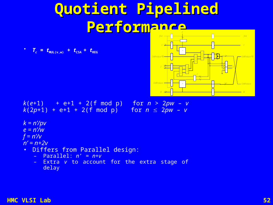
• Tc = tMUL(v,w) + tCSA + tREG
k(e+1) + e+1 + 2(f mod p) for n > 2pw – v k(2p+1) + e+1 + 2(f mod p) for n 2pw – v
k = n’/pve = n’/wf = n’/vn’ = n+2v• Differs from Parallel design:
– Parallel: n’ = n+v– Extra v to account for the extra stage of delay
Y
first
Z
X
*
3:2
CS
A
3:2
CS
A
3:2
CS
A
3:2
CS
A
Z
C
* OldReduce
Up
per
Low
er
OldReduce
M M
Y
first
w
v+w
w
w
v
v
w
v+1
v+1
v
v
w-v
w-v
OldReduce*MOldReduce*M

53HMC VLSI Lab
Comparison of LatenciesComparison of Latencies
• Tenca-Koç Radix 2n2/wp + n/p + 2p – 2 n > 2wp – w 2n + n/p + n/w – 2 n 2wp – w
• Improved Radix 2n2/wp + n/w + n/p + p – 1 n > wpn + n/p + 2n/w – 1 n wp
• Very High Radixn2/wpv + 3n/pv + 4p – 2 n > 4wp – 2w 4n/v + n/pv + n/w - 1 n 4wp – 2w
• Parallel Very High Radixn2/wpv + n/pv + n/w + 1 n > 2wp – v 2n/v + n/pv + n/w + 1 n 2wp – v

54HMC VLSI Lab
Latency vs. # of PEsLatency vs. # of PEs
• Assume w = 16, v = 1 or 16• Let m = wvp be the amount of HW• For small m
– All similar– Cycles m
• For large m– Saturates– High radix
is better10
100
1000
10000
100000
10 100 1000 10000 100000
m = wpv
cycles
tk (256)
tk (1024)
imp (256)
imp(1024)
high(256)
high(1024)
parallel(256)
parallel(1024)
55HMC VLSI Lab
Comparison of Cycle TimesComparison of Cycle Times
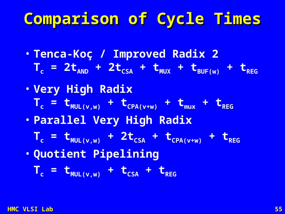
• Tenca-Koç / Improved Radix 2Tc = 2tAND + 2tCSA + tMUX + tBUF(w) + tREG
• Very High RadixTc = tMUL(v,w) + tCPA(v+w) + tmux + tREG
• Parallel Very High Radix
Tc = tMUL(v,w) + 2tCSA + tCPA(v+w) + tREG
• Quotient Pipelining
Tc = tMUL(v,w) + tCSA + tREG

56HMC VLSI Lab
Synthesis ResultsSynthesis Results
• Xilinx Virtex II Pro XC2V250-6– ~5n RAM bits needed for X, Y, M, Z, FIFO
Arch Freq (MHz)
LUTs/PE
Regs/PE
16 × 16 Mults/PE
RAM
Improved Radix 2
144 85
69
0 5n
Very High Radix
107 178
218
2 5n
Parallel Very High Radix
107 133
147
2 5n
Quotient
Pipelined
138 238
226
2 5n

57HMC VLSI Lab
Exponentiation TimesExponentiation Times
• On average, 1.5n + 2 Montgomery multiplies are needed for modular exponentiation– Texp = Tc * latency(n, w, v, p) * (1.5n + 2)

58HMC VLSI Lab
Hardware ResultsHardware Results
Arch Freq (MHz) p n Latency (cycles) Texp (ms)
Improved Radix 2
w = 16
144 16 256 303 0.811024 4239 45.3
64 256 291 0.781024 1167 12.5
Very High Radix
w = v = 16
107 4 256 90 0.321024 1086 15.6
16 256 80 0.281024 330 4.74
Parallel Very High Radix
w = v = 16
107 4 256 85 0.311024 1105 15.9
16 256 50 0.181024 325 4.67
Quotient
Pipelined
w = v = 16
138 4 256 95 0.261024 1139 12.7
16 256 53 0.151024 334 3.72

59HMC VLSI Lab
Athena TeraFire 5008Athena TeraFire 5008
• 5.5 ms 1024-bit exponentiation
• 95 Kgates IP block

60HMC VLSI Lab
Software ResultsSoftware Results
• 1024 bit modular exponentiation– 2.4 GHz Pentium 4, FLINT/C library
• 92 ms without Montgomery’s alg• 41 ms with Montgomery’s alg
– 2.4 GHz Pentium 4, GMP library• 25 ms with Karatsuba’s algs
– 80 MHz ARM• 876 ms with Montgomery’s alg

61HMC VLSI Lab
SummarySummary
• Latency (cycles)– Comparable per full adder for all designs when p small– Saturates when p gets too big
• Improved radix 2 design 2x better than T-K
• Very high radix even better (by v/4 or v/2)
• Cycle Time– Worse for very high radix– But only slightly so on FPGAs with efficient multiplier
hardware
• Total Time– Radix 2 best when little HW is available– Radix 216 attractive for FPGAs for minimum latency when
plenty of HW is available

62HMC VLSI Lab
Future WorkFuture Work
• Better pipelining of parallel design
• Radix 2 parallel design
• Radix 4/8 with precomputed multiples
• Karatsuba Algorithm
• Side channel attack countermeasures
• Reconfigurable Logic on CPUs

63HMC VLSI Lab
Pipelining Parallel DesignPipelining Parallel Design
Y
first
Z
X
*
3:2 CS
A
3:2 CS
A
3:2 CS
A
3:2 CS
A
Z
C
Reduce
Upper
Lower
Reduce
M M
Y
first
w
w
w
v
v
w
v+1
v+1
v
v
w-v
w-v
*
Tc = tMUL(v,w) + 2tCSA + tREG

64HMC VLSI Lab
Parallel Radix 2Parallel Radix 2
• Tc = tAND + 2tCSA + tREG
Z = 0
for i = 0 to n
C = 0
reduce = Z0
for j = 0 to e
(C, Zj) = Zj + C + reduce × Mj + Xi × Yj
Zj-1 = (Zj0, Zj-1
w-1:1)
3:2
CS
A
3:2
CS
A
(w)
Cin
xi
reduce
Z
MY
Z
YM
Cout
Cin
Cout
(w)

65HMC VLSI Lab
Radix 4/8 with Precomputed MultiplesRadix 4/8 with Precomputed Multiples
• Todorov & Twalbeh extended T-K to radix 4/8– Precompute multiples of Y, M– Use mux instead of AND / MUL
• Improve latency using right shifts
• Does Booth encoding help?
• Tc = tMUX + 2tCSA + tREG

66HMC VLSI Lab
Karatsuba AlgorithmKaratsuba Algorithm
• “The Karatsuba multiplication arouses our curiosity, since it seems simple, and one could pleasantly occupy a (preferably rainy) Sunday afternoon trying it out.”– M. Welschenbach, Cryptography in C and C++
• A = A12n + A0; B = B12n + B0
• Regular Multiplication (O(n2))– AB = 22nA1B1 + 2n(A0B1 + A1B0) + A0B0
• Karatsuba Multiplication (O(n1.585))– C0 = A0B0; C1 = A1B1; C2 = (A0 + A1)(B0 + B1) – C0 – C1
– AB = 22nC1 + 2nC2 + C0
67HMC VLSI Lab
Side Channel AttacksSide Channel Attacks
• Monitor chip activity to try deducing private key– Timing– Current consumption– Photon emissions
• How vulnerable is very high radix MM to side channel attacks?
• How can it be improved?– CVSL, other differential logic families?– Differential registers– Inherent symmetry of addition & multiplication

68HMC VLSI Lab
Reconfigurable Logic on CPUReconfigurable Logic on CPU
• Add FPGA for dynamically reconfigurable accelerators– ~1000 transistors / 4-input LUT
• Differentiates Intel from competition by unique reconfigurable logic fabric

69HMC VLSI Lab
ApplicationsApplications
• Montgomery Mult – RSA, ECC, Diffie-Hellman Key Exchange
• AES accelerator – symmetric key crypto
• Viterbi decoder • Pattern matching
– Genome BLAST, Google, network security
• DSP accelerators – photoshop filters, video encoding

70HMC VLSI Lab
ExampleExample
Montecito
2 cores 28.5M Tran each
24MB L3$ 1550M Transistors
Alternative
2 cores 20MB L3$
1300M Transistors250 KLUT FPGA
250M Transistors
FPGA
FPGA

71HMC VLSI Lab
Superblock OrganizationSuperblock Organization
• Each contain substantial resources– CLBs, memories, multipliers, etc.
• Chip provides one or more superblock– Accelerators are compiled for one or
more Superblocks– Easy reconfiguration without recompile– “Memory manager” controls how many
can be downloaded at a time

72HMC VLSI Lab
ConclusionsConclusions
• High radix best when multipliers are cheap– Is this a research direction of relevance to
Intel?
• Focus of future research– Low radix improvements– Side channel security– FPGA coprocessor architectures– Other Discussion ?