Embed Size (px)
Citation preview
Reciprocity-induced symmetry in the round-trip transmission through complex systems
SZU-YU LEE,1,2 VICENTE J. PAROT,1 BRETT E. BOUMA,1,2,3
AND MARTIN VILLIGER1,*
1Harvard Medical School and Massachusetts General Hospital, Wellman Center for Photomedicine, Boston, MA 02114, USA 2 Harvard-MIT Health Sciences and Technology, Massachusetts Institute of Technology, Cambridge, MA 02139, USA 3 Institute for Medical Engineering and Science, Massachusetts Institute of Technology, Cambridge, MA 02139, USA
*Corresponding author: *[email protected]
Abstract:
Reciprocity is a fundamental principle of wave physics and directly relates to the symmetry in the transmission through
a system when interchanging the input and output. The coherent transmission matrix (TM) is a convenient method to
characterize wave transmission through general media. Here we demonstrate the optical reciprocal nature of complex
media by exploring their TM properties. We measured phase-corrected TMs of forward and round-trip propagation in
a single polarization state through a looped 1m-long step-index optical multimode fiber (MMF) to experimentally
verify a transpose relationship between forward and backward transmission. This symmetry impedes straightforward
MMF calibration from proximal measurements of the round-trip TM. Furthermore, we show how focusing through
the MMF with digital optical phase conjugation is compromised by system loss, since time reversibility relies on
power conservation. These insights may inform development of new imaging techniques through complex media and
coherent control of waves in photonic systems.
I. Introduction
The bi-directional transmission through photonic systems is governed by the universal Lorentz reciprocity (or
Helmholtz reciprocity), which states that light propagating along a reversed path experiences the exact same
transmission coefficient as in the forward direction, independent of the path complexity [1,2] or the presence of loss
[3–5]. In the linear regime, this suggests a definite relation, or symmetry, between the forward and the backward
transmission when interchanging the source and detector. This symmetry not only underlies the behavior of common
optical components like polarizers, beam-splitters, and wave-plates, but also engenders surprising physical phenomena
in complex systems such as coherent backscattering (or weak localization) and Anderson localization [6,7]. Optical
phase conjugation is a well-known consequence of this symmetry in loss-free systems, whereby an original light
distribution is replicated by reversing the propagation direction of the detected field while conjugating its wave-front.
Digital optical phase conjugation (DOPC) has been well established for focusing and imaging through complex or
disordered media, including multimode fibers (MMFs) [8–11]. However, the more general underlying transmission
symmetry of bi-directional light transmission through complex systems and its implications have not been explicitly
demonstrated and discussed.
Light transmission through MMFs is typically considered a chaotic process, as the modal scrambling results in the
generation of random speckle patterns at the output [12]. MMFs are of particular interest for studying optical transport
in complex media due to their finite degrees of freedom (DOF) and optical energy confinement. Owing to their high
data transmission capacity in an ultra-small footprint, MMFs have gained significant attention and hold great promise
for optical communication and biomedical endoscopic applications [13,14]. For instance, once measured, the
apparently chaotic transmission through a MMF can be harnessed to relay image information from the distal to the
proximal fiber end, enabling the reconstruction of an image of the distal object [15–17]. Nevertheless, imaging through
MMFs remains technically challenging, and exploring fundamental properties of MMF light transmission may help
develop new strategies to advance MMF-based imaging and endoscopy [18].
In the present study, we investigate MMF transmission properties using a monochromatic coherent transmission
matrix (TM) formalism [19,20] and experimentally demonstrate the transpose symmetry between the forward and
backward TMs in this complex medium imposed by general optical reciprocity. The TM description is a subpart of
the common scattering matrix formalism [1,21,22] and offers a simpler framework that decouples the input and output
channels. We also show that while DOPC enables focusing through MMF, the focusing performance declines with
increasing loss since the time reversibility is corrupted when power is not conserved. Finally, we discuss the
implications of the resulting transpose symmetry on calibrating MMF transmission with only access to the proximal
Th
is is
the au
thor’s
peer
revie
wed,
acce
pted m
anus
cript.
How
ever
, the o
nline
versi
on of
reco
rd w
ill be
diffe
rent
from
this v
ersio
n onc
e it h
as be
en co
pyed
ited a
nd ty
pese
t. PL
EASE
CIT
E TH
IS A
RTIC
LE A
S DO
I: 10.1
063/5
.0021
285
side, which is critical for practical MMF imaging. The gained insights are readily applicable to general electromagnetic
transport in complex and disordered media.
II. Results
2.1 Measuring the single-pass forward Tfw and double-pass round-trip T2X of a MMF
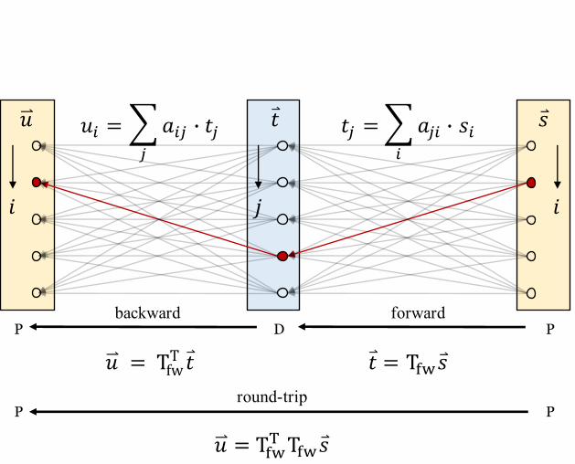
As shown in Fig. 1, the optical transmission through a general medium from an input surface to an output surface can
be expressed by a TM, where each element is a complex coefficient specifying the amplitude and phase evolution of
the transmitted monochromatic field between the corresponding pair of input and output spatial channels. The spatial
channels correspond to the sampling locations on the input and output surfaces, respectively, and are assumed to be
sufficiently dense to correctly sample the electromagnetic fields. We can then express forward light transmission, Tfw,
from the proximal to distal end as
𝑡 = Tfw𝑠, (1)
where 𝑡 and 𝑠 are vectorized representations of the distal output field and proximal input field, respectively. If 𝑡 and 𝑠
are ordered first by the spatial modes, and then by polarization, Tfw can be partitioned into four blocks
Tfw = [TXH TXV
TYH TYV], (2)
where the subscripts X, Y and H, V denote two orthogonal polarization states on the distal and proximal side,
respectively. The backward light transmission from the distal to proximal end can be written as
�⃑⃑� = Tbw𝑡, (3)
where �⃑⃑� and 𝑡 are the proximal output field and distal input field, respectively. According to the reciprocity theorem,
light propagating along the reversed path between input and output will experience the same transmission coefficient
as in the forward direction. In the context of Jones matrices, which describe the relation between the polarization states
of the input and the output field propagating through an optical system, de Hoop’s notion of reciprocity manifests as
a transpose relationship between the Jones matrices describing forward and reverse transmissions [2]. By analogy with
the Jones matrix formalism, when interchanging the input and output spatial channels of the medium, reciprocity
instructs that Tbw is the transpose of Tfw:
Tbw = TTfw = [
TXHT TYH
T
TXVT TYV
T], (4)
where the superscript T indicates the regular matrix transpose. Also, since sequential light transmission is modeled as
TM multiplication, the round-trip transmission through the same medium, T2X (light transmits to and is reflected from
the distal side, then travels back to the proximal side) equals the product of Tbw and Tfw:
T2X = TbwTfw = TTfwTfw, (5)
making T2X a transpose symmetric matrix,
T2X = [TXH
T TXH + TYHT TYH TXH
T TXV + TYHT TYV
TXVT TXH + TYV
T TYH TXVT TXV + TYV
T TYV
] = TT2X. (6)
Of note, the two on-diagonal blocks are self-transpose-symmetric, and the two off-diagonal blocks are instead the
transpose of each other.
Th
is is
the au
thor’s
peer
revie
wed,
acce
pted m
anus
cript.
How
ever
, the o
nline
versi
on of
reco
rd w
ill be
diffe
rent
from
this v
ersio
n onc
e it h
as be
en co
pyed
ited a
nd ty
pese
t. PL
EASE
CIT
E TH
IS A
RTIC
LE A
S DO
I: 10.1
063/5
.0021
285
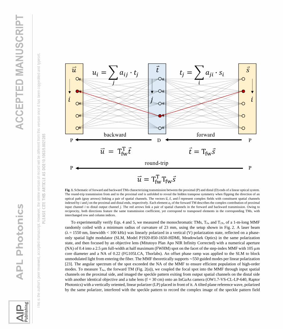
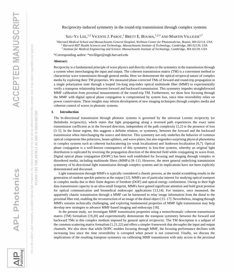
Fig. 1. Schematic of forward and backward TMs characterizing transmission between the proximal (P) and distal (D) ends of a linear optical system.
The round-trip transmission from and to the proximal end is unfolded to reveal the hidden transpose symmetry when flipping the direction of an
optical path (gray arrows) linking a pair of spatial channels. The vectors �⃑⃑�, 𝑠, and 𝑡 represent complex fields with constituent spatial channels
indexed by i and j on the proximal and distal ends, respectively. Each element aji of the forward TM describes the complex contribution of proximal
input channel i to distal output channel j. The red arrows link a pair of spatial channels in the forward and backward transmission. Owing to
reciprocity, both directions feature the same transmission coefficient, yet correspond to transposed elements in the corresponding TMs, with
interchanged row and column indices.
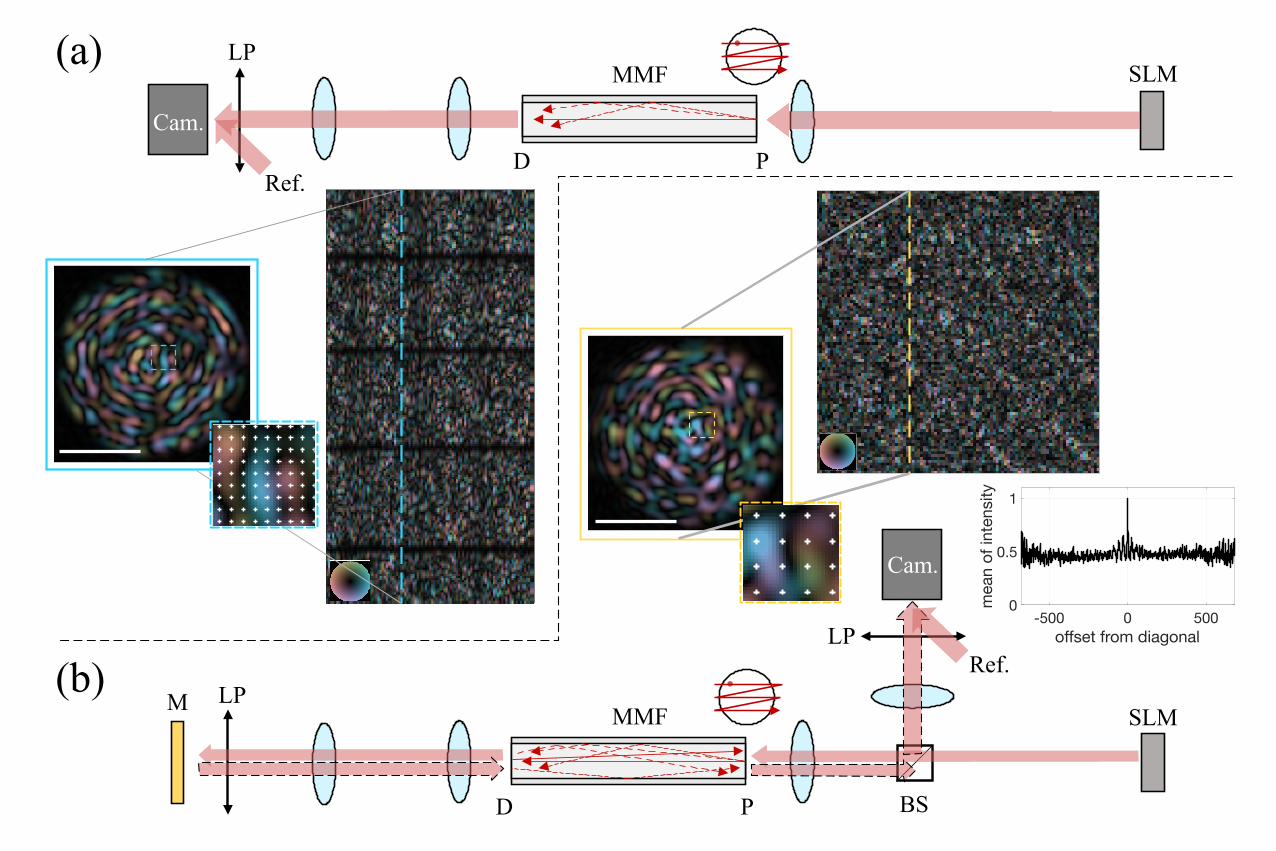
To experimentally verify Eqs. 4 and 5, we measured the monochromatic TMs, Tfw and T2X, of a 1-m-long MMF
randomly coiled with a minimum radius of curvature of 23 mm, using the setup shown in Fig. 2. A laser beam
(λ = 1550 nm, linewidth < 100 kHz) was linearly polarized in a vertical (V) polarization state, reflected on a phase-
only spatial light modulator (SLM, Model P1920-850-1650-HDMI, Meadowlark Optics) in the same polarization
state, and then focused by an objective lens (Mitutoyo Plan Apo NIR Infinity Corrected) with a numerical aperture
(NA) of 0.4 into a 2.5 µm full-width at half maximum (FWHM) spot on the facet of the step-index MMF with 105 m
core diameter and a NA of 0.22 (FG105LCA, Thorlabs). An offset phase ramp was applied to the SLM to block
unmodulated light from entering the fiber. The MMF theoretically supports ∼550 guided modes per linear polarization
[23]. The angular spectrum of the spot exceeded the NA of the MMF to ensure efficient population of high-order
modes. To measure Tfw, the forward TM (Fig. 2(a)), we coupled the focal spot into the MMF through input spatial
channels on the proximal side, and imaged the speckle pattern exiting from output spatial channels on the distal side
with another identical objective and a tube lens (f = 30 cm) onto an InGaAs camera (OW1.7-VS-CL-LP-640, Raptor
Photonics) with a vertically oriented, linear polarizer (LP) placed in front of it. A tilted plane reference wave, polarized
by the same polarizer, interfered with the speckle pattern to record the complex image of the speckle pattern field
Th
is is
the au
thor’s
peer
revie
wed,
acce
pted m
anus
cript.
How
ever
, the o
nline
versi
on of
reco
rd w
ill be
diffe
rent
from
this v
ersio
n onc
e it h
as be
en co
pyed
ited a
nd ty
pese
t. PL
EASE
CIT
E TH
IS A
RTIC
LE A
S DO
I: 10.1
063/5
.0021
285
through off-axis holography in the V polarization state. If we consider the V polarizers at the proximal and distal sides
as part of the system whose TM we are measuring, then TYV = TVV and Tfw becomes:
Tfw = [0 0
0 TVV]. (7)
To release digital storage burden, we down-sampled the complex image at a defined grid of 2637 positions. To
uniformly probe all MMF guided modes, this procedure was repeated in an oversampling fashion for a dense grid of
695 equally spaced illuminating foci sequentially generated by phase gradients on the SLM. Rearranging column by
column the ensemble of vectorized complex output images recorded over all input spatial channels constructed the
Tfw representing the linear transformation of light traveling from the proximal facet to the distal facet. Due to the
difference in the number of input and output sampling positions, the Tfw is a tall rectangular matrix.
For measuring T2X, the double-pass TM, as shown in Fig. 2(b), we again sequentially coupled light into the MMF
from the proximal end through the same set of input spatial channels. On the distal side, we replaced the camera used
for measuring in the forward transmission with a gold-coated mirror to reflect the light back into the MMF. The same
V linear polarizer, previously in front of the camera and now in front of the gold-coated mirror, was necessary to
maintain the identical Tfw and avoid polarization cross-talk. In general, the spatial and polarization DOF are coupled
through mode mixing during light propagation in the MMF, and the MMF output polarization states are different from
the input polarization state [24]. With the distal and proximal V linear polarizers, we measure the transmission from
a V linear input polarization state into a V linear output polarization state, both for the forward and the double-pass
TMs. The T2X of Eq. 6 simplifies in this case to:
T2X = [0 0
0 TVVT TVV
]. (8)
On the proximal side, we recorded the round-trip transmission by decoupling its path from the illumination with a
non-polarizing beam-splitter. To preserve the symmetry between the illumination and the detection configurations and
to obtain a square matrix T2X, we sampled the recorded output fields at the 695 positions defined by the input focus
positions. Furthermore, to mitigate specular reflections at both the distal and proximal facets, wedge prism mounting
shims (SM1W1122, Thorlabs) filled with index-matching gel (G608N3, Thorlabs) were used to cover both facets for
measurements of forward and double-pass TMs. Intriguingly, the round-trip measurements through individual
proximal spatial channels allow us to observe the coherent backscattering effect, which guarantees constructive
interference in pairs of time-reversed optical paths, and thus light is statistically twice as likely to exit through the
same spatial channel that it used to couple into the fiber than through any other output channel [6]. In the TM
formalism, this corresponds to a ratio of two between the mean intensities of the main diagonal and off-diagonal
elements in T2X, as plotted in Fig. 2(b). Mathematically, if we assume the elements in Tfw feature independent real and
imaginary parts following identical normal distributions, then Eq. 5 states that T2X is the same as a pseudo-covariance
matrix (or relation matrix) of proper complex random vectors [25,26], resulting in the factor of two due to Gaussian
statistics.
In our experiments, we used a single polarization for illumination and detection to avoid the experimental
complexity of measuring polarization-resolved TMs [27]. Furthermore, the X and Y polarization states at the distal
side were identical to the H and V polarizations at the proximal side. Measuring the round-trip TM without the distal
V polarizer would still result in a transpose symmetric matrix T2X, but the coupling between the polarization states
would create a second term TTHVTHV. Hence, the distal V polarizer was required when measuring the round-trip TM to
be able to relate T2X to the measured TVV of Tfw. The polarization degree of freedom simply extends the DOF of the
spatial modes, and in analogy to the partition of the transmission matrix into the four polarization blocks of Eq. 5, we
could also partition TVV into any two subsets of input and output spatial modes. Thus, TVV can likewise be defined as
being composed by four blocks, which express the transmissions from the two input subsets to the two output subsets.
The measured round-trip matrix TTVVTVV contains two on-diagonal blocks that are self-transpose-symmetric and two
off-diagonal blocks that are the transpose of each other. By extension, the experimentally verified symmetry relation
holds for any combination of spatial channels and polarization states and holds without loss of generality.
Th
is is
the au
thor’s
peer
revie
wed,
acce
pted m
anus
cript.
How
ever
, the o
nline
versi
on of
reco
rd w
ill be
diffe
rent
from
this v
ersio
n onc
e it h
as be
en co
pyed
ited a
nd ty
pese
t. PL
EASE
CIT
E TH
IS A
RTIC
LE A
S DO
I: 10.1
063/5
.0021
285
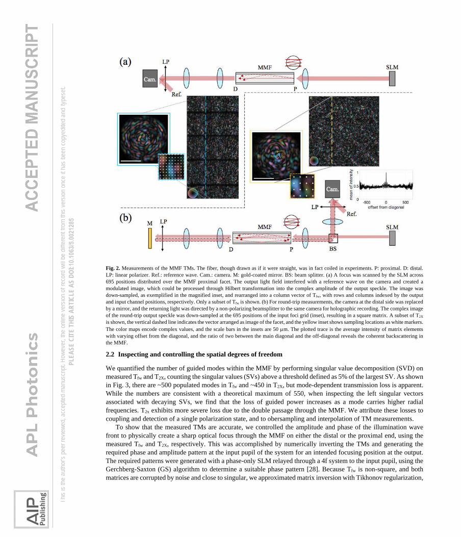
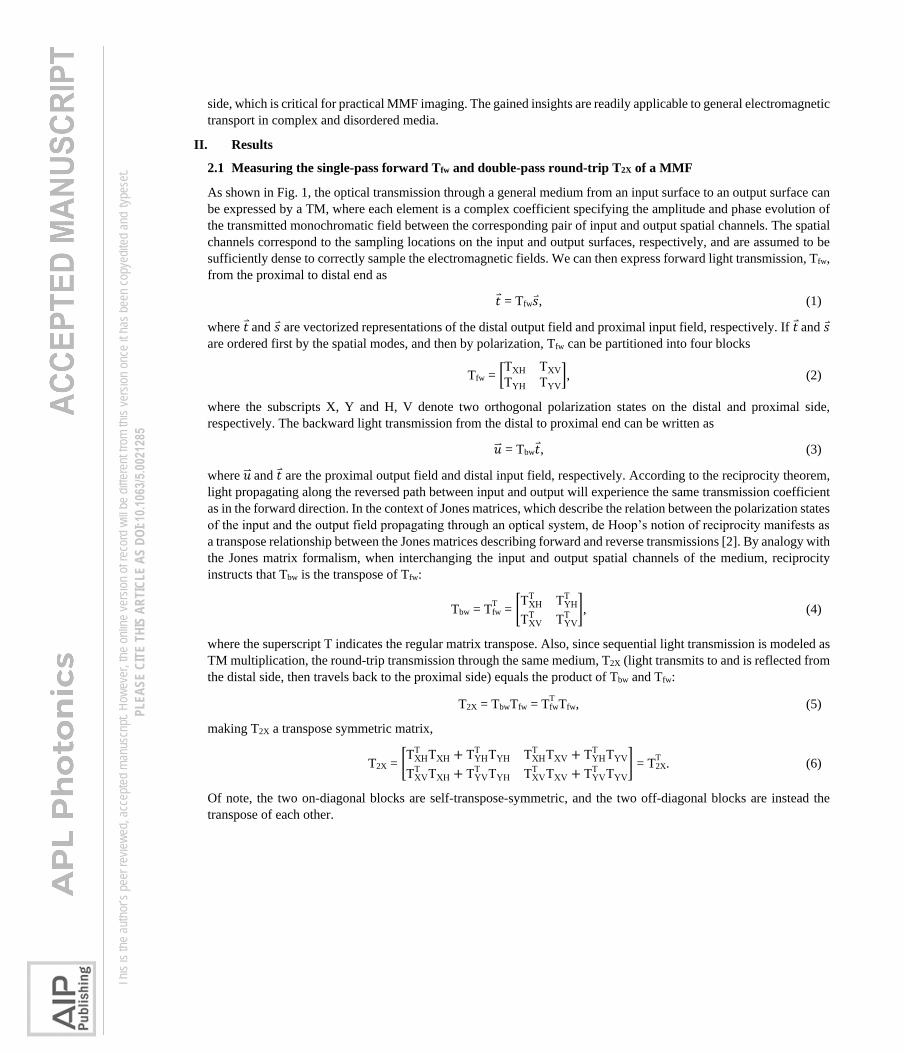
Fig. 2. Measurements of the MMF TMs. The fiber, though drawn as if it were straight, was in fact coiled in experiments. P: proximal. D: distal.
LP: linear polarizer. Ref.: reference wave. Cam.: camera. M: gold-coated mirror. BS: beam splitter. (a) A focus was scanned by the SLM across
695 positions distributed over the MMF proximal facet. The output light field interfered with a reference wave on the camera and created a
modulated image, which could be processed through Hilbert transformation into the complex amplitude of the output speckle. The image was
down-sampled, as exemplified in the magnified inset, and rearranged into a column vector of Tfw, with rows and columns indexed by the output
and input channel positions, respectively. Only a subset of Tfw is shown. (b) For round-trip measurements, the camera at the distal side was replaced
by a mirror, and the returning light was directed by a non-polarizing beamsplitter to the same camera for holographic recording. The complex image
of the round-trip output speckle was down-sampled at the 695 positions of the input foci grid (inset), resulting in a square matrix. A subset of T2X
is shown, the vertical dashed line indicates the vector arranged as image of the facet, and the yellow inset shows sampling locations as white markers.
The color maps encode complex values, and the scale bars in the insets are 50 m. The plotted trace is the average intensity of matrix elements
with varying offset from the diagonal, and the ratio of two between the main diagonal and the off-diagonal reveals the coherent backscattering in
the MMF.
2.2 Inspecting and controlling the spatial degrees of freedom
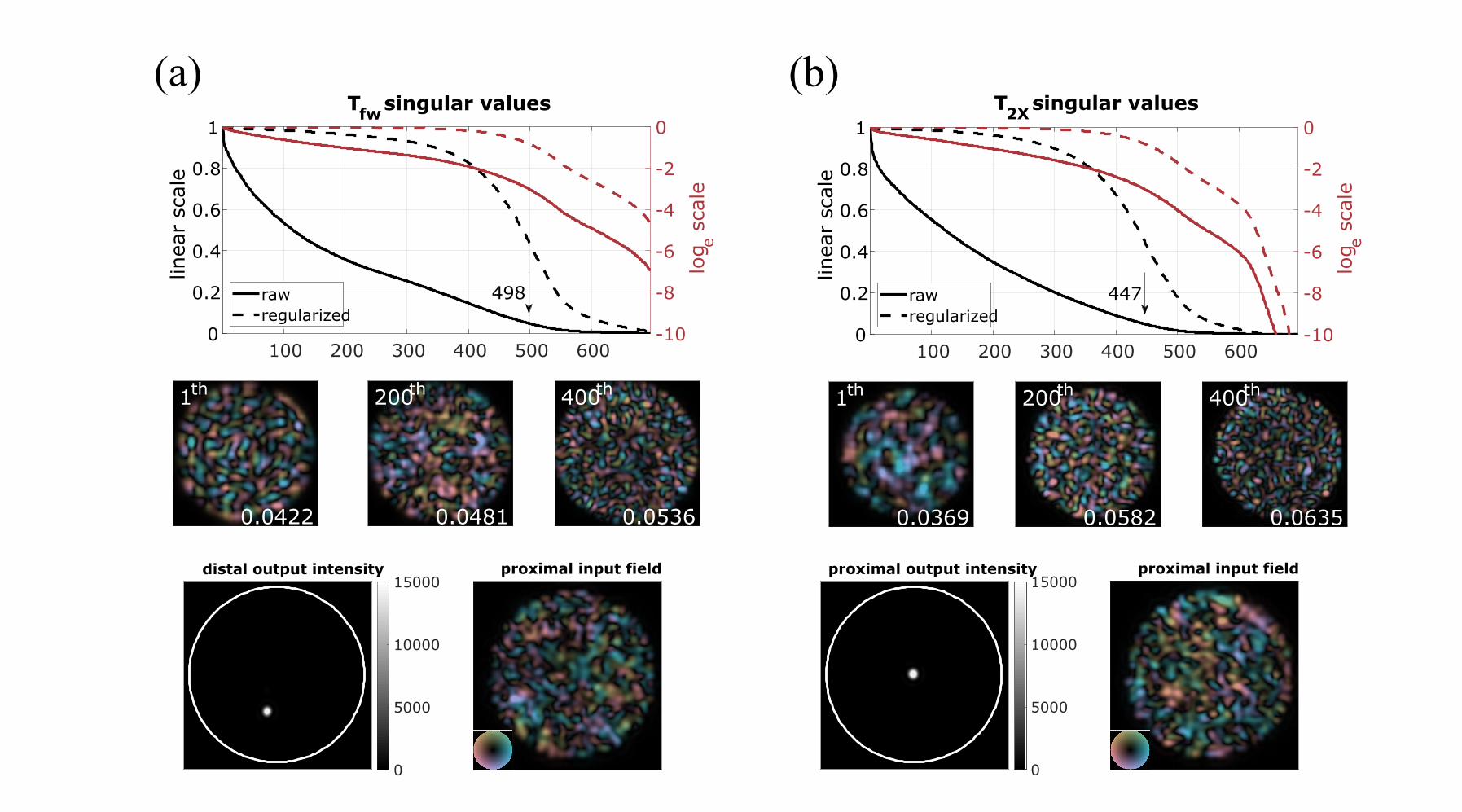
We quantified the number of guided modes within the MMF by performing singular value decomposition (SVD) on
measured Tfw and T2X, counting the singular values (SVs) above a threshold defined as 5% of the largest SV. As shown
in Fig. 3, there are ~500 populated modes in Tfw and ~450 in T2X, but mode-dependent transmission loss is apparent.
While the numbers are consistent with a theoretical maximum of 550, when inspecting the left singular vectors
associated with decaying SVs, we find that the loss of guided power increases as a mode carries higher radial
frequencies. T2x exhibits more severe loss due to the double passage through the MMF. We attribute these losses to
coupling and detection of a single polarization state, and to obersampling and interpolation of TM measurements.
To show that the measured TMs are accurate, we controlled the amplitude and phase of the illumination wave
front to physically create a sharp optical focus through the MMF on either the distal or the proximal end, using the
measured Tfw and T2X, respectively. This was accomplished by numerically inverting the TMs and generating the
required phase and amplitude pattern at the input pupil of the system for an intended focusing position at the output.
The required patterns were generated with a phase-only SLM relayed through a 4f system to the input pupil, using the
Gerchberg-Saxton (GS) algorithm to determine a suitable phase pattern [28]. Because Tfw is non-square, and both
matrices are corrupted by noise and close to singular, we approximated matrix inversion with Tikhonov regularization,
Th
is is
the au
thor’s
peer
revie
wed,
acce
pted m
anus
cript.
How
ever
, the o
nline
versi
on of
reco
rd w
ill be
diffe
rent
from
this v
ersio
n onc
e it h
as be
en co
pyed
ited a
nd ty
pese
t. PL
EASE
CIT
E TH
IS A
RTIC
LE A
S DO
I: 10.1
063/5
.0021
285
T-1 (tik), with the regularization parameter, 𝛾, chosen as 10% of the greatest SV. This is justified based on the L-curve
method [29]. The product of Tfw with its regularized inverse is identical to the multiplication of a modified TM with
its Hermitian transpose. The modification consists of rescaling each SV, 𝜎, of the TM by 1 √𝜎2 + 𝛾2⁄ , and is shown
in dashed curves (labeled as “regularized”) in Fig. 3. Examples of the V polarization of the created foci are shown in
the bottom row of Fig. 3, with ~4 µm average FWHM. We defined a focus contrast (FC) as the ratio of the peak
intensity at the focal point over the average intensity across all output spatial channels to evaluate the focusing
performance. This FC metric is similar to the enhancement factor defined by Vellekoop et al. [30,31], but it is bounded
by the number of guided modes in the MMF even in a lossless condition and expresses accurately what fraction of the
DOFs is effectively controlled. The average FCs for distal and proximal focusing were ~205.7 and ~148.3, respectively.
Whereas the maximal FC, calculated when assuming the total power is concentrated in a single output spatial channel,
would be 550 given the theoretical number of modes per polarization, the experimental FCs are limited by several
factors such as the MMF loss, finite persistence time of the system, the measurement noise, the imperfect wave-front
shaping, and the finite camera dynamic range. Despite the discrepancy between the experimental and theoretical values,
the achieved FCs agree with the quantified number of modes, suggesting that we were reasonably exploiting the
available DOF.
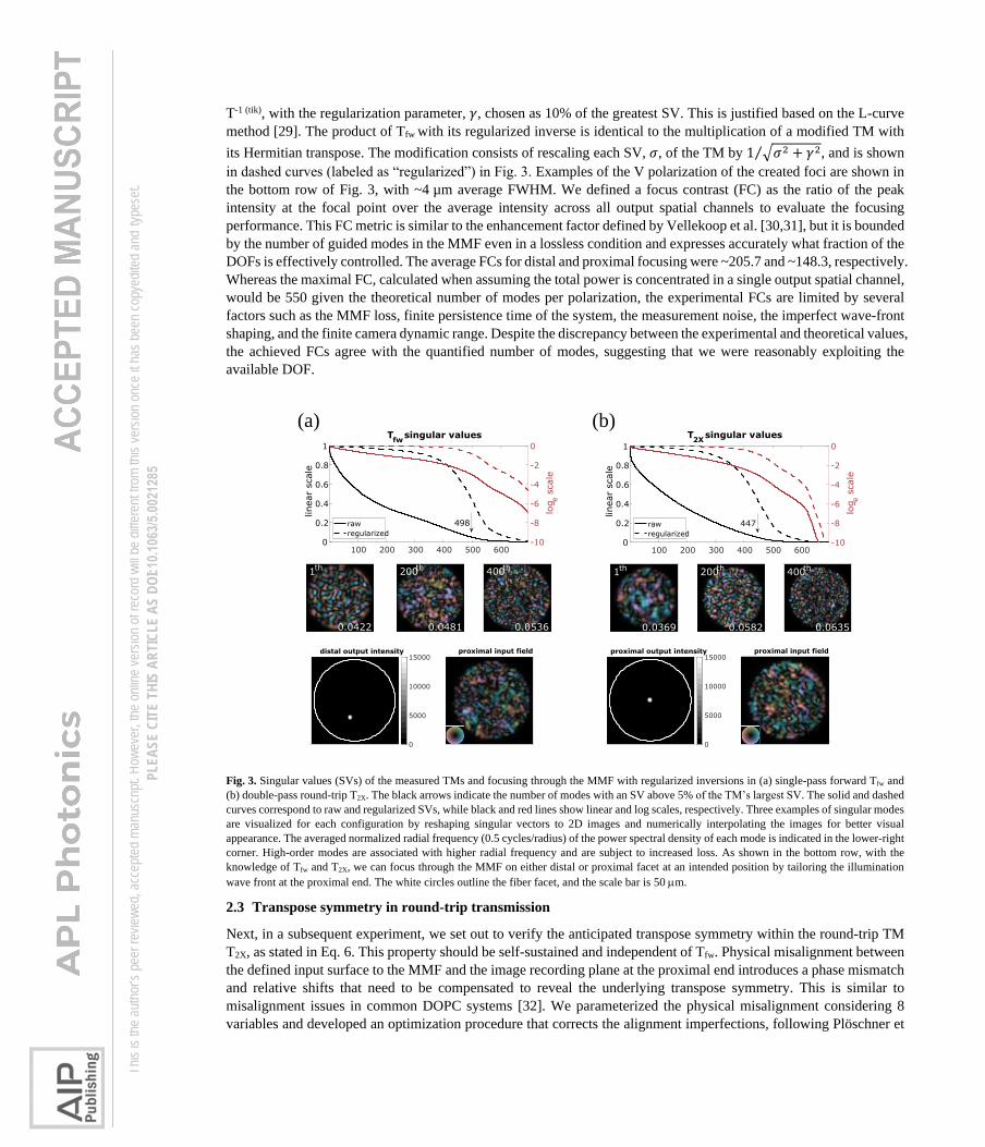
Fig. 3. Singular values (SVs) of the measured TMs and focusing through the MMF with regularized inversions in (a) single-pass forward Tfw and
(b) double-pass round-trip T2X. The black arrows indicate the number of modes with an SV above 5% of the TM’s largest SV. The solid and dashed
curves correspond to raw and regularized SVs, while black and red lines show linear and log scales, respectively. Three examples of singular modes
are visualized for each configuration by reshaping singular vectors to 2D images and numerically interpolating the images for better visual
appearance. The averaged normalized radial frequency (0.5 cycles/radius) of the power spectral density of each mode is indicated in the lower-right
corner. High-order modes are associated with higher radial frequency and are subject to increased loss. As shown in the bottom row, with the
knowledge of Tfw and T2X, we can focus through the MMF on either distal or proximal facet at an intended position by tailoring the illumination
wave front at the proximal end. The white circles outline the fiber facet, and the scale bar is 50 m.
2.3 Transpose symmetry in round-trip transmission
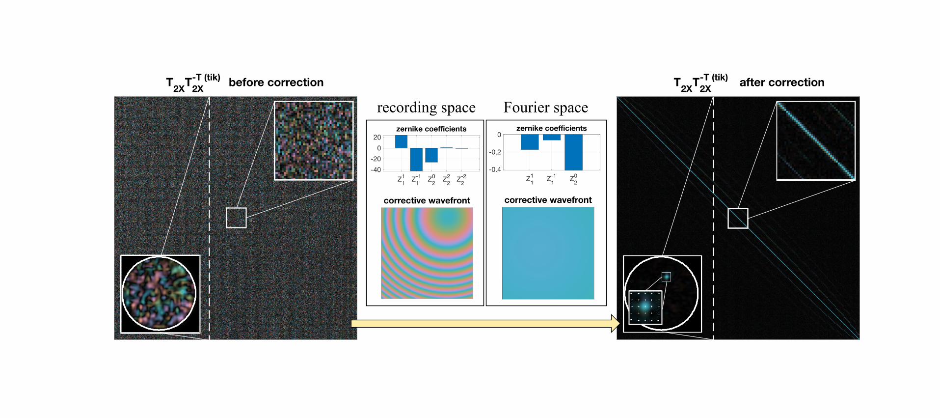
Next, in a subsequent experiment, we set out to verify the anticipated transpose symmetry within the round-trip TM
T2X, as stated in Eq. 6. This property should be self-sustained and independent of Tfw. Physical misalignment between
the defined input surface to the MMF and the image recording plane at the proximal end introduces a phase mismatch
and relative shifts that need to be compensated to reveal the underlying transpose symmetry. This is similar to
misalignment issues in common DOPC systems [32]. We parameterized the physical misalignment considering 8
variables and developed an optimization procedure that corrects the alignment imperfections, following Plöschner et
proximal output intensity
0
5000
10000
15000proximal input field
0
0.1
0.2
0.3
0.4
0.5
0.6
0.7
0.8
0.9
1
distal output intensity
0
5000
10000
15000proximal input field
0
0.1
0.2
0.3
0.4
0.5
0.6
0.7
0.8
0.9
1
100 200 300 400 500 6000
0.2
0.4
0.6
0.8
1
linear
scale
-10
-8
-6
-4
-2
0
loge s
cale
T2X
singular values
447raw
regularized
100 200 300 400 500 6000
0.2
0.4
0.6
0.8
1
linear
scale
-10
-8
-6
-4
-2
0
loge s
cale
Tfw
singular values
498raw
regularized
(a) (b)
400th
0.0635
1th
0.0369
200th
0.0582
1th
0.0422
200th
0.0481
400th
0.0536
Th
is is
the au
thor’s
peer
revie
wed,
acce
pted m
anus
cript.
How
ever
, the o
nline
versi
on of
reco
rd w
ill be
diffe
rent
from
this v
ersio
n onc
e it h
as be
en co
pyed
ited a
nd ty
pese
t. PL
EASE
CIT
E TH
IS A
RTIC
LE A
S DO
I: 10.1
063/5
.0021
285
al. [27]. To address the phase mismatch, we applied a two-dimensional (2D) phase term constituted by Zernike
polynomials in the recording space of the output spatial channels. This corresponds to a diagonal phase-only matrix
left-multiplied with T2X. The Zernike orders correspond to 2D tilts, defocus, and 2D astigmatisms. To register the
positional shifts, we applied another phase term with 2D tilts and defocus in the Fourier space of the output spatial
channels of T2X, as this is the same as lateral and axial translation of the observation coordinates. This correction is
equivalent to convolving the output spatial channels with a complex and offset point spread function. In the TM
formalism, this is a further left-multiplication of T2X with a Toeplitz matrix. The Zernike coefficients were determined
by minimizing the error |T’T2X – T’
2X|2, where T’2X is the corrected T2X, and |·|2 is the squared Frobenius matrix norm.
Without correction, the initial error, normalized by |T2X|2, was 200%. With correction, the normalized error was
reduced to 23%. For comparison, we found a 15% residual error when computing the normalized squared Frobenius
norm of the difference between two sequentially measured round-trip TMs of the identical MMF transmission. To
investigate transpose symmetry, we verified the diagonal localization in the product of the matrix by its inverse
transpose. The product of the uncorrected T2X with its Tikhonov regularized transpose matrix inversion T2X−T (tik)
is a
chaotic matrix due to the disordered interference between populated modes caused by the physical misalignment (Fig.
4). However, after applying the correction, the product of T’2X with T’2X
–T (tik) became close to the identity matrix, with
the integrated on-diagonal energy over the total matrix energy improving from 0.24% to 43.5%. As benchmark, the
same metric applied to a perfectly symmetric TM, (T’T2X + T’
2X)/2, resulted in 59.2% on-diagonal energy, limited by
the regularized matrix inversion. These results show that the phase-corrected round-trip TM matches its transpose,
thus demonstrating its transpose symmetry.
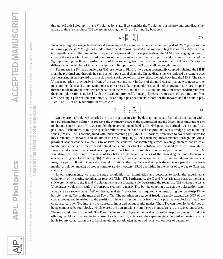
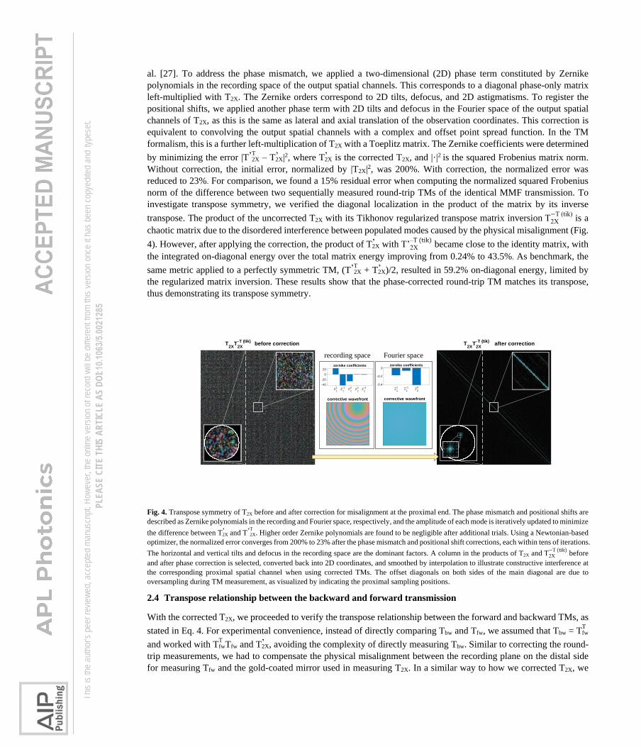
Fig. 4. Transpose symmetry of T2X before and after correction for misalignment at the proximal end. The phase mismatch and positional shifts are
described as Zernike polynomials in the recording and Fourier space, respectively, and the amplitude of each mode is iteratively updated to minimize
the difference between T’2X and T’T
2X. Higher order Zernike polynomials are found to be negligible after additional trials. Using a Newtonian-based
optimizer, the normalized error converges from 200% to 23% after the phase mismatch and positional shift corrections, each within tens of iterations.
The horizontal and vertical tilts and defocus in the recording space are the dominant factors. A column in the products of T2X and T2X
−T (tik) before
and after phase correction is selected, converted back into 2D coordinates, and smoothed by interpolation to illustrate constructive interference at
the corresponding proximal spatial channel when using corrected TMs. The offset diagonals on both sides of the main diagonal are due to
oversampling during TM measurement, as visualized by indicating the proximal sampling positions.
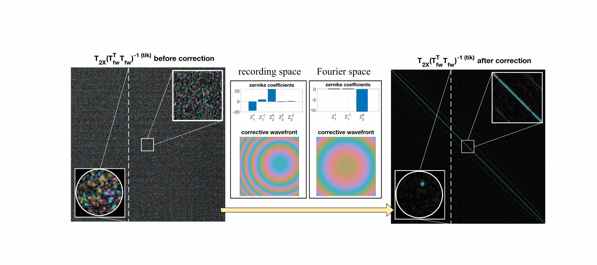
2.4 Transpose relationship between the backward and forward transmission
With the corrected T2X, we proceeded to verify the transpose relationship between the forward and backward TMs, as
stated in Eq. 4. For experimental convenience, instead of directly comparing Tbw and Tfw, we assumed that Tbw = TTfw
and worked with TTfwTfw and T’
2X, avoiding the complexity of directly measuring Tbw. Similar to correcting the round-
trip measurements, we had to compensate the physical misalignment between the recording plane on the distal side
for measuring Tfw and the gold-coated mirror used in measuring T2X. In a similar way to how we corrected T2X, we
zernike coefficients
Z1
1Z
1
-1Z
2
0Z
2
2Z
2
-2-40
-20
0
20
corrective wavefront
zernike coefficients
Z1
1Z
1
-1Z
2
0-0.4
-0.2
0
corrective wavefront
recording space Fourier space
T2X
T2X
-T (tik) before correction T
2XT
2X
-T (tik) after correction
Th
is is
the au
thor’s
peer
revie
wed,
acce
pted m
anus
cript.
How
ever
, the o
nline
versi
on of
reco
rd w
ill be
diffe
rent
from
this v
ersio
n onc
e it h
as be
en co
pyed
ited a
nd ty
pese
t. PL
EASE
CIT
E TH
IS A
RTIC
LE A
S DO
I: 10.1
063/5
.0021
285
applied phase terms to the recording and Fourier spaces of the output spatial channels of Tfw. In this case, we aimed
to minimize the error |T’2X – T’
TfwT’
fw|2, where T’fw is the corrected Tfw. Fig. 5 shows that the misalignment, characterized
by the amplitude of the Zernike polynomials, was quite different from that encountered in T2X. Without correction to
Tfw, the initial error, normalized by |T’2X|2, was 101%, and the product of T’
2X and (TTfwTfw)-1 (tik) appeared far from a
diagonal matrix, implying low resemblance between T’2X and T
TfwTfw. Clearly, the random background denotes that the
physical misalignment caused undesired interference over all spatial channels. Crucially, the normalized error reduced
to 27.7% after correction, which is again close to the experimental benchmark of 15%. Additionally, the resultant
product closely resembled the identity matrix, with its integrated on-diagonal energy over the total matrix energy
improving from 0.27% to 36.6%. The product of T’2X with its regularized inverse reached 56.8% on-diagonal energy.
Therefore, we conclude that T’2X and T’
TfwT’
fw, at least as measured in a single polarization state, are identical to each
other, as stated in Eq. 5, which implies that the backward transmission Tbw is the same as TTfw, as described in Eq. 4.
This provides evidence of general optical reciprocity and the ensuing transpose symmetry for transmission through a
MMF, which serves as a convenient model for general complex media.
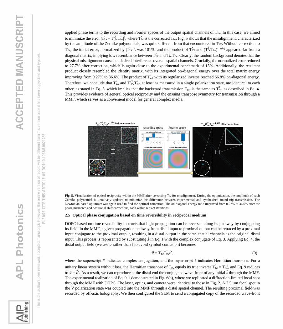
Fig. 5. Visualization of optical reciprocity within the MMF after correcting Tfw for misalignment. During the optimization, the amplitude of each
Zernike polynomial is iteratively updated to minimize the difference between experimental and synthesized round-trip transmission. The
Newtonian-based optimizer was again used to find the optimal correction. The on-diagonal energy ratio improved from 0.27% to 36.6% after the
phase mismatch and positional shift corrections, each within tens of iterations.
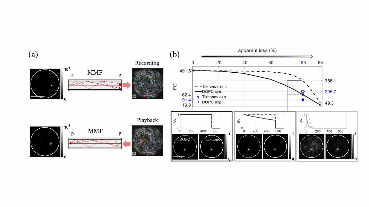
2.5 Optical phase conjugation based on time reversibility in reciprocal medium
DOPC based on time reversibility instructs that light propagation can be reversed along its pathway by conjugating
its field. In the MMF, a given propagation pathway from distal input to proximal output can be retraced by a proximal
input conjugate to the proximal output, resulting in a distal output in the same spatial channels as the original distal
input. This process is represented by substituting 𝑠 in Eq. 1 with the complex conjugate of Eq. 3. Applying Eq. 4, the
distal output field (we use �⃑� rather than 𝑡 to avoid symbol confusion) becomes
�⃑� = TfwT†fw𝑡*, (9)
where the superscript * indicates complex conjugation, and the superscript † indicates Hermitian transpose. For a
unitary linear system without loss, the Hermitian transpose of Tfw equals its true inverse T†fw = Tfw
-1, and Eq. 9 reduces
to �⃑� = 𝑡*. As a result, we can reproduce at the distal end the conjugated wave-front of any initial 𝑡 through the MMF.
The experimental realization of Eq. 9 is demonstrated in Fig. 6(a), where we replicated a diffraction-limited focal spot
through the MMF with DOPC. The laser, optics, and camera were identical to those in Fig. 2. A 2.5 µm focal spot in
the V polarization state was coupled into the MMF through a distal spatial channel. The resulting proximal field was
recorded by off-axis holography. We then configured the SLM to send a conjugated copy of the recorded wave-front
corrective wavefront
zernike coefficients
Z1
1Z
1
-1Z
2
0
-10
-5
0
corrective wavefront
zernike coefficients
Z1
1Z
1
-1Z
2
0Z
2
2Z
2
-2-20
0
20
T2X
(Tfw
TT
fw)-1 (tik)
before correction T2X
(Tfw
TT
fw)-1 (tik)
after correction
recording space Fourier space
Th
is is
the au
thor’s
peer
revie
wed,
acce
pted m
anus
cript.
How
ever
, the o
nline
versi
on of
reco
rd w
ill be
diffe
rent
from
this v
ersio
n onc
e it h
as be
en co
pyed
ited a
nd ty
pese
t. PL
EASE
CIT
E TH
IS A
RTIC
LE A
S DO
I: 10.1
063/5
.0021
285
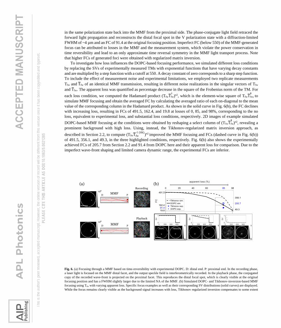
in the same polarization state back into the MMF from the proximal side. The phase-conjugate light field retraced the
forward light propagation and reconstructs the distal focal spot in the V polarization state with a diffraction-limited
FWHM of ~4 µm and an FC of 91.4 at the original focusing position. Imperfect FC (below 550) of the MMF-generated
focus can be attributed to losses in the MMF and the measurement system, which violate the power conservation in
time reversibility and lead to an only approximate time reversal symmetry in the MMF light transport process. Note
that higher FCs of generated foci were obtained with regularized matrix inversion.
To investigate how loss influences the DOPC-based focusing performance, we simulated different loss conditions
by replacing the SVs of experimentally measured TMs with exponential functions that have varying decay constants
and are multiplied by a step function with a cutoff at 550. A decay constant of zero corresponds to a sharp step function.
To include the effect of measurement noise and experimental limitations, we employed two replicate measurements
Tfw and T̃fw of an identical MMF transmission, resulting in different noise realizations in the singular vectors of Tfw
and T̃fw. The apparent loss was quantified as percentage decrease in the square of the Frobenius norm of the TM. For
each loss condition, we computed the Hadamard product (TfwT̃†fw)º2, which is the element-wise square of TfwT̃
††fw, to
simulate MMF focusing and obtain the averaged FC by calculating the averaged ratio of each on-diagonal to the mean
value of the corresponding column in the Hadamard product. As shown in the solid curve in Fig. 6(b), the FC declines
with increasing loss, resulting in FCs of 491.5, 162.4, and 19.8 at losses of 0, 85, and 98%, corresponding to the no
loss, equivalent to experimental loss, and substantial loss conditions, respectively. 2D images of example simulated
DOPC-based MMF focusing at the conditions were obtained by reshaping a select column of (TfwT̃††fw)º2, revealing a
prominent background with high loss. Using, instead, the Tikhonov-regularized matrix inversion approach, as
described in Section 2.2, to compute (TfwT̃fw
-1 (tik))º2 improved the MMF focusing and FCs (dashed curve in Fig. 6(b))
of 491.5, 356.1, and 49.3, in the three highlighted conditions, respectively. Fig. 6(b) also shows the experimentally
achieved FCs of 205.7 from Section 2.2 and 91.4 from DOPC here and their apparent loss for comparison. Due to the
imperfect wave-front shaping and limited camera dynamic range, the experimental FCs are inferior.
Fig. 6. (a) Focusing through a MMF based on time-reversibility with experimental DOPC. D: distal end. P: proximal end. In the recording phase,
a laser light is focused on the MMF distal facet, and the output speckle field is interferometrically recorded. In the playback phase, the conjugated
copy of the recorded wave-front is projected on the proximal facet. This reproduces the distal focal spot, which is clearly visible at the original
focusing position and has a FWHM slightly larger due to the limited NA of the MMF. (b) Simulated DOPC- and Tikhonov-inversion-based MMF
focusing using Tfw with varying apparent loss. Specific focus examples as well as their corresponding SV distributions (solid curves) are displayed.
While the focus remains clearly visible as the background signal increases with loss, Tikhonov regularized inversion compensates to some extent
PD MMF
(a) (b)Recording
Playback
PDMMF
DOPC Tikhonov
Th
is is
the au
thor’s
peer
revie
wed,
acce
pted m
anus
cript.
How
ever
, the o
nline
versi
on of
reco
rd w
ill be
diffe
rent
from
this v
ersio
n onc
e it h
as be
en co
pyed
ited a
nd ty
pese
t. PL
EASE
CIT
E TH
IS A
RTIC
LE A
S DO
I: 10.1
063/5
.0021
285
for the mode-dependent loss (dashed curves) and improves the FCs, depending on the loss condition. The white circles outline the fiber facet, and
the scale bars are 50 m.
III. Discussion
Optical reciprocity is a universal principle within linear, non-magnetic, and static media, even in the presence of loss.
It has been previously shown in various formalisms and contexts [1,2,33,34] and extends to complex media such as a
MMF. We investigated symmetry constraints that reciprocity imposes on bi-directional light transport through a MMF
and measured the forward and double-pass TMs, Tfw and T2X, to demonstrate that TT2X = T2X and T2X = T
TfwTfw. The
round-trip transmission reveals a transpose symmetry, and the backward transmission presents a transpose relationship
to the forward transmission. Experimentally we used a single polarization state for illumination and detection and
hence our measurements correspond only to a subset of the full modes supported by the MMF. Since there is no
fundamental difference between spatial and polarization DOF, we assume this symmetry to also hold for polarization-
resolved TMs. We also showed that focusing through a MMF with DOPC, which relies on time reversibility by
assuming a loss-free transmission, may have limitation when in practice the transmission suffers from non-negligible
loss. This means that reciprocity alone is insufficient for time reversibility, which furthermore requires the absence of
losses.
When the MMF is truly loss-free, and we have a fully sampled Tfw with uniform SVs, the number of degrees of
control is the same as the number of available DOF. In this case, TfwT†fw is a low-pass filtered identity matrix,
suggesting that we can focus through the MMF based on DOPC and achieve an FC close to the number of guided
modes. Noise is the only limiting factor, and DOPC- and Tikhonov-inversion based MMF focusing have the same
performance. In our experimental condition, the MMF may leak some of the modes, and only measuring a single
polarization state intrinsically eliminates all power in the orthogonal polarization states. Nevertheless, using DOPC
we could still generate a focal spot with an FC of 91.4 through a lossy MMF, treating the transmission as an
approximately unitary system, for which T†fw ~ Tfw
-1. On the other hand, experimental focusing through the MMF with
regularized TM inversion achieved a better FC of more than 200. This is because the Tikhonov regularization
numerically compensates the mode-dependent loss and creates a balanced constructive interference, providing a better
focusing performance. However, if the MMF transmission is dissipative, TfwT†fw is far from an identity matrix, and the
generated focus with DOPC barely stands out from the speckle background. In this regime, using Tikhonov
regularization may only have modest benefit, since it only compensates for SVs experiencing modest loss. The DOF
corresponding to SVs smaller than the regularization parameter remain uncontrolled and do not contribute to the
constructive interference at intended focus locations.
The implementation of a flexible MMF endoscope remains technically challenging despite recently proposed
strategies [27,35–40], and the lack of flexibility is the enduring bottleneck for MMF imaging applications. Because
the TMs of MMFs are notoriously sensitive to physical fiber deformation [27], a flexible MMF endoscope would
demand repeated on-site calibration without open distal access in practical endoscopic settings. Imaging through
MMFs with certain flexibility based on data-driven approaches has been reported, yet relying on a transmissive regime
that requires open distal access [38,39]. Although calibrating a MMF with only proximal access is a desirable strategy,
robust experimental MMF proximal calibration methods remain to be demonstrated. Understanding the reciprocal
nature of light propagation through a MMF and the underlying symmetry constraints may help tackle this challenge.
In the context of proximal MMF calibration, where measurement of T2X may be available, the demonstrated symmetry
constraint precludes straightforward recovery of Tfw or Tbw, which is needed for imaging through the MMF
[15,27,41,42]. To appreciate this limitation, we can factor Tfw into its symmetric and anti-symmetric part based on the
second polar decomposition [43],
Tfw = AL, (10)
where A is orthogonal (AT = A-1), and L is transpose symmetric (LT = L). In this case Eq. 5 becomes
T2X = L2. (11)
The orthogonal parts cancel each other upon forward and backward transmission, preserving only the symmetric part
in the round-trip transmission measurement. Eq. 11 states a fundamental restriction: while the symmetric part of Tfw
can be uniquely retrieved by taking the matrix square-root of the proximally measured T2X [44], if it has no negative
Th
is is
the au
thor’s
peer
revie
wed,
acce
pted m
anus
cript.
How
ever
, the o
nline
versi
on of
reco
rd w
ill be
diffe
rent
from
this v
ersio
n onc
e it h
as be
en co
pyed
ited a
nd ty
pese
t. PL
EASE
CIT
E TH
IS A
RTIC
LE A
S DO
I: 10.1
063/5
.0021
285
real eigenvalues, the orthogonal part, A, vanishes due to the intrinsic propagation property imposed by the optical
reciprocity. Put differently, although a square, complex-valued matrix of dimension M has 2M2 unknown coefficients,
the transpose symmetry reduces this number to M2 + M, masking the additional M2 – M of the orthogonal component.
This leads to symmetric degeneracy of Tfw even though T2X is known. This explains why Tfw cannot be directly
retrieved from T2X, which complicates strategies for MMF proximal calibration methods.
Previously, Takagi matrix factorization has been proposed to help in recovering Tfw from proximal measurements
[37]. A carefully engineered static reflector installed at the distal end of a MMF can provide distinctive reflectivity on
individual distal spatial channels, which augments Eq. 5 to
T2X = TTfwRTfw, (12)
where R is a real-valued diagonal matrix with sortable on-diagonal elements. By performing Takagi factorization on
the accessible T2X and leveraging the transpose symmetry, we have
T2X = UTU, (13)
where U is a unitary matrix, and is a real-valued diagonal matrix. If the MMF is loss-free, this would suggest R =
and Tfw = DU, where D is an unknown diagonal matrix with entries that are ± 1 and might be estimated with prior
knowledge. Unfortunately, as shown in Fig. 3, Tfw is generally lossy, which compromises this strategy. Based on our
findings and arguments, breaking the intrinsic transpose symmetry in the round-trip transmission, installing a
calibration element capable of several realizations at the MMF distal end, or introducing new constraints by measuring
multispectral round-trip transmission to resolve the degeneracy issue might be the most viable solution towards a
flexible MMF endoscope [6,37,40]. Since reciprocity is ubiquitous, the symmetry principle may also inform non-
invasive imaging, coherent wave-control through highly scattering tissues, and electromagnetic communications.
In conclusion, optical reciprocity imposes a symmetry on the bi-directional propagation through a general complex
medium regardless of the path complexity or loss. We experimentally demonstrated this symmetry in a looped 1-m-
long step-index MMF by measuring the forward and round-trip transmissions. The symmetry prohibits direct retrieval
of the forward TM from a round-trip measurement. Thus MMF endoscopy in a practical setting is fundamentally
complicated due to the need to calibrate the MMF without distal access. The insights of light transport within a MMF
obtained here may stimulate improved strategies for flexible MMF endoscopy and facilitate efficient sensing and
imaging techniques through complex or disordered media.
IV. Acknowledgements
Research in this publication was supported by the National Institute of Biomedical Imaging and Bioengineering of the
National Institutes of Health, award P41 EB015903. VJP was supported by the OSA Deutsch fellowship.
V. Data availability
The data that support the findings of this study are available from the corresponding author upon reasonable request.
References:
1. H. A. Haus, Waves and Fields in Optoelectronics (Prentice-Hall, 1984).
2. R. J. Potton, "Reciprocity in optics," Reports Prog. Phys. 67(5), 717–754 (2004).
3. L. Onsager, "Reciprocal Relations in Irreversible Processes. I.," Phys. Rev. 37(4), 405–426 (1931).
4. H. B. G. Casimir, "Reciprocity Theorems and Irreversible Processes," Proc. IEEE 51(11), 1570–1573 (1963).
5. M. G. Silveirinha, "Hidden time-reversal symmetry in dissipative reciprocal systems," Opt. Express 27(10), 14328 (2019).
6. Y. Bromberg, B. Redding, S. M. Popoff, and H. Cao, "Control of coherent backscattering by breaking optical reciprocity," Phys. Rev.
A 93(2), 1–16 (2016).
7. D. S. Wiersma, "Breaking reciprocity," Nat. Photonics 6(8), 506–507 (2012).
8. M. Cui and C. Yang, "Implementation of a digital optical phase conjugation system and its application to study the robustness of
turbidity suppression by phase conjugation," Opt. Express 18(4), 3444–3455 (2010).
9. I. N. Papadopoulos, S. Farahi, C. Moser, and D. Psaltis, "Focusing and scanning light through a multimode optical fiber using digital
phase conjugation," Opt. Express 20(10), 10583–10590 (2012).
10. Z. Yaqoob, D. Psaltis, M. S. Feld, and C. Yang, "Optical phase conjugation for turbidity suppression in biological samples," Nat.
Photonics 2(2), 110–115 (2008).
11. I. M. Vellekoop, M. Cui, and C. Yang, "Digital optical phase conjugation of fluorescence in turbid tissue," Appl. Phys. Lett. 101(8),
81108 (2012).
12. A. P. Mosk, A. Lagendijk, G. Lerosey, and M. Fink, "Controlling waves in space and time for imaging and focusing in complex
media," Nat. Photonics 6(5), 283–292 (2012).
13. D. Psaltis and C. Moser, "Imaging with Multimode Fibers," Opt. Photonics News (January), 14–16 (2010).
Th
is is
the au
thor’s
peer
revie
wed,
acce
pted m
anus
cript.
How
ever
, the o
nline
versi
on of
reco
rd w
ill be
diffe
rent
from
this v
ersio
n onc
e it h
as be
en co
pyed
ited a
nd ty
pese
t. PL
EASE
CIT
E TH
IS A
RTIC
LE A
S DO
I: 10.1
063/5
.0021
285
14. D. J. Richardson, J. M. Fini, and L. E. Nelson, "Space-division multiplexing in optical fibres," Nat. Photonics 7(5), 354–362 (2013).
15. Y. Choi, C. Yoon, M. Kim, T. D. Yang, C. Fang-Yen, R. R. Dasari, K. J. Lee, and W. Choi, "Scanner-free and wide-field endoscopic
imaging by using a single multimode optical fiber," Phys. Rev. Lett. 109(20), 1–5 (2012).
16. T. Čižmár and K. Dholakia, "Exploiting multimode waveguides for pure fibre-based imaging," Nat. Commun. 3, (2012).
17. P. Caramazza, O. Moran, R. Murray-Smith, and D. Faccio, "Transmission of natural scene images through a multimode fibre," Nat.
Commun. 10(1), 2029 (2019).
18. S. Li, S. A. R. Horsley, T. Tyc, T. Cizmar, and D. B. Phillips, "Guide-star assisted imaging through multimode optical fibres," arXiv
2005.06445, (2020).
19. S. M. Popoff, G. Lerosey, R. Carminati, M. Fink, A. C. Boccara, and S. Gigan, "Measuring the Transmission Matrix in Optics: An
Approach to the Study and Control of Light Propagation in Disordered Media," Phys. Rev. Lett. 104(10), 100601 (2010).
20. S. Popoff, G. Lerosey, M. Fink, A. C. Boccara, and S. Gigan, "Image transmission through an opaque material," Nat. Commun. 1(1), 81
(2010).
21. S. M. Popoff, G. Lerosey, R. Carminati, M. Fink, A. C. Boccara, and S. Gigan, "Measuring the transmission matrix in optics: An
approach to the study and control of light propagation in disordered media," Phys. Rev. Lett. 104(10), 1–4 (2010).
22. D. Jalas, A. Petrov, M. Eich, W. Freude, S. Fan, Z. Yu, R. Baets, M. Popović, A. Melloni, J. D. Joannopoulos, M. Vanwolleghem, C. R.
Doerr, and H. Renner, "What is — and what is not — an optical isolator," Nat. Photonics 7(8), 579–582 (2013).
23. A. Yariv and P. Yeh, Photonics : Optical Electronics in Modern Communications (Oxford University Press, 2007).
24. W. Xiong, C. W. Hsu, Y. Bromberg, J. E. Antonio-Lopez, R. Amezcua Correa, and H. Cao, "Complete polarization control in
multimode fibers with polarization and mode coupling," Light Sci. Appl. 7(1), 54 (2018).
25. F. D. Neeser and J. L. Massey, "Proper complex random processes with applications to information theory," IEEE Trans. Inf. Theory
39(4), 1293–1302 (1993).
26. B. Picinbono, "Second-order complex random vectors and normal distributions," IEEE Trans. Signal Process. 44(10), 2637–2640
(1996).
27. M. Plöschner, T. Tyc, and T. Čižmár, "Seeing through chaos in multimode fibres," Nat. Photonics 9(8), 529–535 (2015).
28. G. Yang, B. Dong, B. Gu, J. Zhuang, and O. K. Ersoy, "Gerchberg–Saxton and Yang–Gu algorithms for phase retrieval in a nonunitary
transform system: a comparison," Appl. Opt. 33(2), 209–218 (1994).
29. P. C. Hansen, The L-Curve and Its Use in the Numerical Treatment of Inverse Problems (WIT Press, 2000).
30. I. M. Vellekoop and A. P. Mosk, "Universal Optimal Transmission of Light Through Disordered Materials," Phys. Rev. Lett. 101(12),
120601 (2008).
31. I. M. Vellekoop, "Feedback-based wavefront shaping," Opt. Express 23(9), 12189 (2015).
32. M. Jang, H. Ruan, H. Zhou, B. Judkewitz, and C. Yang, "Method for auto-alignment of digital optical phase conjugation systems based
on digital propagation," Opt. Express 22(12), 14054 (2014).
33. Z. Sekera, "Scattering Matrices and Reciprocity Relationships for Various Representations of the State of Polarization," J. Opt. Soc.
Am. 56(12), 1732–1740 (1966).
34. P. P. Khial, A. D. White, and A. Hajimiri, "Nanophotonic optical gyroscope with reciprocal sensitivity enhancement," Nat. Photonics
12(11), 671–675 (2018).
35. A. M. Caravaca Aguirre, E. Niv, D. B. Conkey, and R. Piestun, "Real time focusing through a perturbed multimode fiber," Imaging
Appl. Opt. CTh2B.4 (2013).
36. S. Farahi, D. Ziegler, I. N. Papadopoulos, D. Psaltis, and C. Moser, "Dynamic bending compensation while focusing through a
multimode fiber," Opt. Express 21(19), 22504 (2013).
37. R. Y. Gu, R. N. Mahalati, and J. M. Kahn, "Design of flexible multi-mode fiber endoscope," Opt. Express 23(21), 26905 (2015).
38. J. Zhao, Y. Sun, Z. Zhu, J. E. Antonio-Lopez, R. A. Correa, S. Pang, and A. Schülzgen, "Deep Learning Imaging through Fully-
Flexible Glass-Air Disordered Fiber," ACS Photonics 5(10), 3930–3935 (2018).
39. P. Fan, T. Zhao, and L. Su, "Deep learning the high variability and randomness inside multimode fibers," Opt. Express 27(15), 20241
(2019).
40. G. S. D. Gordon, M. Gataric, A. G. C. P. Ramos, R. Mouthaan, C. Williams, J. Yoon, T. D. Wilkinson, and S. E. Bohndiek,
"Characterizing Optical Fiber Transmission Matrices Using Metasurface Reflector Stacks for Lensless Imaging without Distal Access,"
Phys. Rev. X 9(4), 41050 (2019).
41. D. Loterie, S. Farahi, I. Papadopoulos, A. Goy, D. Psaltis, and C. Moser, "Digital confocal microscopy through a multimode fiber,"
Opt. Express 23(18), 23845 (2015).
42. N. Borhani, E. Kakkava, C. Moser, and D. Psaltis, "Learning to see through multimode fibers," Optica 5(8), 960–966 (2018).
43. R. Bhatia, "The bipolar decomposition," Linear Algebra Appl. 439(10), 3031–3037 (2013).
44. C. R. Johnson, K. Okubo, and R. Reams, "Uniqueness of matrix square roots and an application," Linear Algebra Appl. 323, 51–60
(2001).
Th
is is
the au
thor’s
peer
revie
wed,
acce
pted m
anus
cript.
How
ever
, the o
nline
versi
on of
reco
rd w
ill be
diffe
rent
from
this v
ersio
n onc
e it h
as be
en co
pyed
ited a
nd ty
pese
t. PL
EASE
CIT
E TH
IS A
RTIC
LE A
S DO
I: 10.1
063/5
.0021
285
PP Dforward
𝑡 = T%&𝑠
𝑖𝑗𝑖
𝑡* =+𝑎*--
. 𝑠-
backward
𝑢 = TfwT 𝑡
𝑢- = +𝑎-**
. 𝑡*
round-trip
𝑢 = T%&3 T%&𝑠PP
𝑡 𝑠𝑢
(a)
(b)
Cam.
LPMMF
D P
Cam.
MMF
D P
LPM
BS
SLM
Ref.
Ref.
SLM
LP-500 0 500
offset from diagonal
0
0.5
1
mea
n of
inte
nsity
proximal output intensity
0
5000
10000
15000proximal input field
0
0.1
0.2
0.3
0.4
0.5
0.6
0.7
0.8
0.9
1distal output intensity
0
5000
10000
15000proximal input field
0
0.1
0.2
0.3
0.4
0.5
0.6
0.7
0.8
0.9
1
100 200 300 400 500 6000
0.2
0.4
0.6
0.8
1
linea
r sc
ale
-10
-8
-6
-4
-2
0
log e
scal
e
T2X singular values
447rawregularized
100 200 300 400 500 6000
0.2
0.4
0.6
0.8
1
linea
r sc
ale
-10
-8
-6
-4
-2
0
log e
scal
e
Tfw singular values
498rawregularized
(a) (b)
400th
0.0635
1th
0.0369
200th
0.0582
1th
0.0422
200th
0.0481
400th
0.0536
zernikecoefficients
Z11 Z
1-1 Z
20 Z
22 Z
2-2
-40
-20
0
20
correctivewavefront
zernikecoefficients
Z11 Z
1-1 Z
20
-0.4
-0.2
0
correctivewavefront
recording space Fourier space
T2X
T2X-T(tik) before correction T
2XT2X-T(tik) after correction
correctivewavefront
zernikecoefficients
Z11 Z
1-1 Z
20
-10
-5
0
correctivewavefront
zernikecoefficients
Z11 Z
1-1 Z
20 Z
22 Z
2-2
-20
0
20
T2X(T
fwT T
fw)-1(tik) beforecorrection T
2X(T
fwT T
fw)-1(tik) aftercorrection
recording space Fourier space
PD MMF
(a) (b)Recording
Playback
PDMMF
DOPC Tikhonov