Embed Size (px)
Citation preview

Vot, +MR 21, NUMRRR $ QOToBER, 19 19
. . .157sica. . .. .1eery eI.' . ~ erromagnetic .DomainsCHARLES KITTKL
Bel/ Telephone Laboratories, Murray Hill, 1Vew Jersey
1. Survey of Domain Theory1.1 Introduction1.2 The domain assumption1.3 The origin of domains1.4 Coercive force, hysteresis, and reversible permeability
2. Contributions to the Domain Energy2.1 Exchange2.2 Magnetocrystalline (anisotropy)2.3 Magnetoelastic2.4 Magnetostatic
3. The Bloch Wall3.1 Introductory remarks3.2 Estimate of thickness and energy of Sloch wall3.3 180' walls in (100) plane of iron
4. Theoretical Domain Structure4.1 Introduction4.2 Flux closure domain configurations
5. Experimental Studies of Domains5.1 Powder pattern technique5.2 Powder pattern results
6. Magnetic Properties of Small Particles6.1 Critical particle size for single domain behavior6.2 Coercive force of small particles
7. Initial Permeability and Coercive Force7.1 General remarks7.2 Kersten inclusion theory7.3 Strain theory7.4 Neel magnetization Quctuation theory
Appendix A: Mathematical expressions for the anisotropy ofcubic crystals.
Appendix 8: Magnetic interaction energy of dipoles on a cubiclattice.
Appendix C: List of Symbols.
1. SURVEY OF DOMAIN THEORY
1.1 Introduction' 'N recent years there has been a major growth of thei. body of experimental and theoretical knowledgeregarding the origin and behavior of ferromagneticdomains. We possess now a general theoretical founda-tion for the subject, a foundation which is intellectuallysatisfying and which has been verified experimentallyin considerable detail in several simple situations inferromagnetic single crystals and, in less detail, in veryfine ferromagnetic powders. The results which have
5
been obtained confirm the theory in all essential aspectsand thus give one conhdence that the more complicatedsituations obtaining in polycrystalline materials maybe understood, at least in qualitative terms, on thebasis of existing theory.
The present paper is undertaken as a comprehensivereview of the physical principles of domain theory andof the crucial experiments which bear directly on thefoundations of the subject. The theory of the origin ofdomains is not treated adequately in the existing text-'books on ferromagnetism; for example, none of theexisting textbooks' discusses the original paper in thisfield, written by Landau and Lifshitz in 1935.
The organization of the present paper falls into twostages. There is erst an introductory survey whichdescribes the basic physical concepts of domain theoryin general non-mathematical terms. The ideas are thendeveloped in detail in the subsequent sections of thepaper.
1.2 The Domain Assumption
The essential aspects of ferromagnetism are illus-trated by the implications of the following experimentalfact
It is possible to change the oner all magnetization -of asuitably prepared ferromagnetic specimen from an initialvalue of zero (in the absence of an applied magnetic geld)to a saturation value of the order of 1000 gauss, by the
application of a geld whose strength may be of the order
of 0.01 oersteds
Such a magnetization curve is shown in Pig. j.. Themagnetization is defined as the magnetic moment perunit volume. The ordinate axis of the curve is, however,Qux density, which in this case is closely equal to 4xtimes the magnetization,
~ A Russian book has just appeared which gives a brief treat-ment of this subject (Vonsovsky and Shur, 1948). (An alphabeticlist of all references is given at the end of this article. )
41

CHARLES K I TTE L
x f0320
12
c/l
0.X
Cl 4
-16
The fact just referred to contains two significantobservations:
(a) It is possible in some cases to attain saturation magnetiza-tion by the application of a very weak magnetic Geld.
(b) It is possible for the magn. etization gf the same specimento be zero in zero (or nearly zero) applied 6eld.
The first observation is remarkable since it is knownfrom the study of paramagnetism that the applicationof a field of 0.01 oersted has an entirely negligibleeffect on the magnetization of a system of free and
(o)PARAMAGNETIC SALT
{OR FERROMAGNETASOVE CURIE POINT)
(e)FERROM AGNET
AT VERY LOW TEMPERATURE
(c)FERROMAGNET
AT LOW TEMPERATURE
{d)FERRONIAGNET
JUST BELOW CURiE POINT
FIG. 2. Orientation of magnetic moments of electrons inparamagnetic and ferromagnetic materials.
-20-0.08 ~06 -0.04 -0.02 0 0.02 0.04 0.06 0.08
H IN OERSTEDS
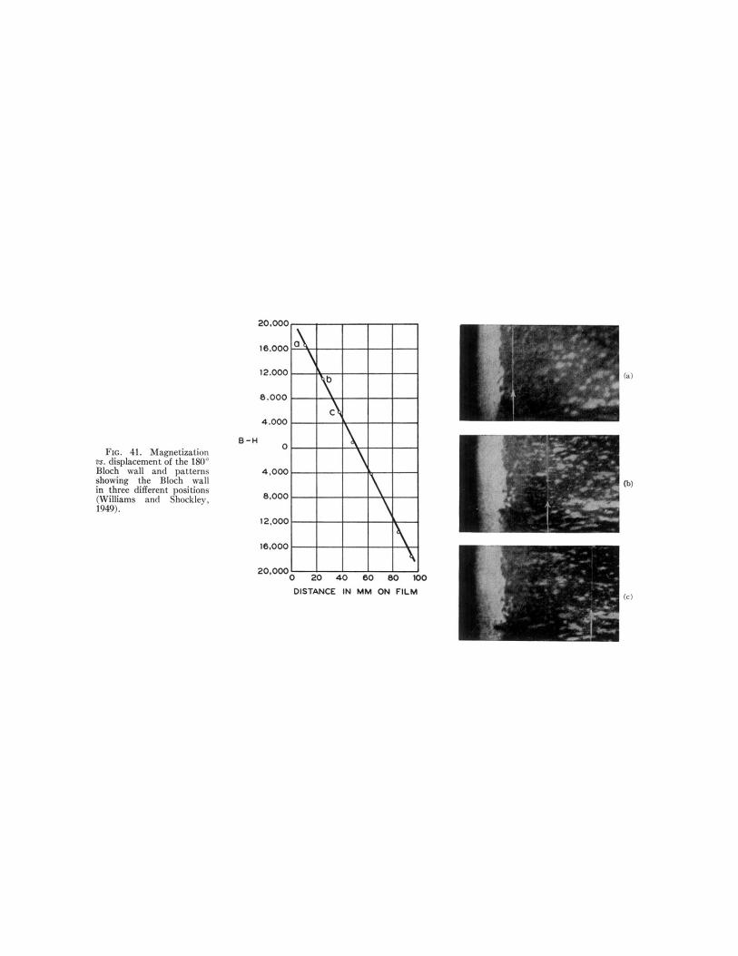
FIG. 1. Magnetization curve of single crystal of silicon iron. The8 scale is only approximate. (Williams and Shockley, 1949.)
independent elementary magnetic moments. For ex-ample, at room temperature a field of 0.01 oersted willincrease the magnetization of a paramagnetic salt suchas ferrous sulfate (FeS04) by about 10 ' gauss, ascompared with 10' gauss in the ferromagnetic specimen.The small e8ect in the case of the paramagnetic salt isknown to be caused by thermal agitation which acts tooppose the ordering inQuence of the applied magneticfield. In the paramagnetic salt electively only onemagnetic moment in 10' is "oriented" by a field of0.01 oersted, so that the distribution of magneticmoment directions remains essentially random. Thishigh degree of chaos is, as we have said, the result ofthe predominant role played by thermal agitation ina system where the electron magnetic moments areindependent, without important mutual interactions.
Pierre gneiss (1907) pointed out that the difficultycaused by thermal agitation could be largely circum-vented if one postulated in ferromagnetic materials theexistence of a powerful internal "molecular" field; wedescribe this now as a mutual interaction betweenelectrons which would tend to line up the magneticmoments parallel to one another.
The required magnitude for the Weiss molecular fieldmay be estimated readily. At the Curie temperatureT, the thermal energy kT. of an electron spin is ofthe same order of magnitude as the interaction energyp~H J of the Inagnetic moment p~ of an electron actedon by the effective molecular field H J ..
kT~= p~Hm~, (1.2.1)
' A list of symbols is given in Appendix C.
so that'
H y= I4T./14m =10 "10'/10 "=10' oersteds. (1.2.2)
This is an exceedingly powerful effective held; it isabout twenty times more intense than any actualmagnetic Geld produced in a laboratory. At tempera-tures below the Curie temperature the eBect of themolecular field outweighs the thermal fluctuation energyand the specimen is accordingly ferromagnetic. Mag-netic moment orientations in paramagnetic and ferro-magnetic materials are illustrated schematically byFig. 2; the variation of the saturation magnetization ofiron as a function of temperature is plotted in Fig. 3.
It is known now that the origin of the molecularfield lies in the quantum-mechanical exchange force;another and better known manifestation of this forceis the chemical valence bond, although in the case ofthe chemical bond the exchange force usually tends tomake the spins of neighboring electrons anti-parallel,instead of parallel as in the case of ferromagnetism.Weiss himself did not make any specific predictionsabout the origin of the molecular field, but he did pointout that the ordinary magnetic moment interactionbetween electrons is much too weak to account for themolecular field. The magnetic held at one lattice point

P H YS I CAL THEORY OF F E RROMAGNE TI C DOM A I NS
arising from the magnetic moment of an electron at aneighboring lattice point is of the order of
).0~ ~
10 "p,g
H= —=r3 (2X 10-')'
= 1000 oersteds, (1.2.3)
which is smaller than the effective molecular field H ~
by a factor of the order of 10 4. The magnetic momentinteraction by itself would lead to a Curie temperaturein the neighborhood of 0.1'K. The situation is quitediferent in dielectric materials, as the order of magni-tude of electric dipole moments is. about 100 timeslarger than magnetic dipole moments, leading to inter-action energies 10' larger. It is therefore not surprisingto find materials which are ferroelectric at room temper-ature, as a result of electric dipole interactions.
We have now seen how the existence of the powerfulWeiss molecular field enables saturation magnetizationto be obtained. How then do we explain statement (b)above, that it is possible for the magnetization to bezero in zero applied field? It seems at first sight contra-dictory, in view of the 10' oersted molecular field, tosuppose that a 10 ' oersted applied field can alter themagnetic moment of the specimen by an appreciableamount.
Weiss extricated the theory from this difficulty bymaking the assumption that actual specimens arecomposed of a number of small regions called domains,within each of which the local magnetization is satu-rated; the directions of magnetization of differentdomains need not necessarily be parallel, however. Aschematic arrangement of domains with zero resultantmagnetic moment is shown in Fig. 4a for a singlecrystal. In polycrystalline samples it was imagined byearly workers that each crystallite might contain asingle domain, and that the resultant magnetic momentcould be zero by virtue of a random distribution ofgrain axes, as indicated in Fig. 4b.
The increase in the value of the resultant magneticmoment of the specimen under the action of an appliedmagnetic field may be imagined to take place on thedomain theory by two independent processes, as wassuggested by R. Becker: by an increase in the volumeof domains which are favorably oriented with respectto the field at the expense of unfavorably orienteddomains; or by rotation of the directions of magnetiza-tion towards the direction of the field. These twomethods by which the resultant magnetization maychange are shown in Fig. 5.
It turns out on closer examination that in weakfields the magnetization changes usually proceed bymeans of domain boundary displacements, so that thedomains change in size. In strong fields the magnetiza-tion usually changes by means of rotation of thedirection of magnetization. A typical magnetizationcurve is shown in Fig. 6, with the regions designatedin which each process is dominant.
0.8—
0.6—0'0
&ce0.4-
~ ~~ ~
~ 4
0.2—
0 I I I 1 I I
0.20 0.30 0.40 0.50 0.60 0.70 0.80TTc
FIG. 3. Saturation magnetization of iron as atemperature. At room temperature the saturationpercent below that obtaining at zero degrees Kelvin.
l
0.90 1.00
function ofvalue is 2.0
We therefore see that Weiss was able to explain theprincipal aspects of ferromagnetism by means of twoassumptions: the existence of the molecular field andthe existence of domain structure. Weiss did not justifyeither of these assumptions in terms of atomic forces.The explanation of the molecular field in terms ofexchange forces was contributed by Heisenberg in 1926,and the explanation of the origin of domains in termsof magnetic field energy was given by Landau andLifshitz in 1935.
We go on now to consider qualitatively the causesresponsible for the formation of domains.
/
t
FIG. 4. Schematic domainarrangements for zero resultantmagnetic moment in a singlecrystal (a) and in a polcrystal-line specimen (b). The domainstructure of the polycrystallinespecimen has been drawn forsimplicity as if each crystallitecontained only a single domain;this is not usually the case.
to)SINGLE CRYSTAL
(b)POLYCRYSTAL
1.3 The Origin of Domains
In this section we shall show that domain structureis a natural consequence of the various contributionsto the energy —exchange, anisotropy, and magnetic-of a ferromagnetic body. But first it is appropriate toconsider brieQy the experimental evidence for theexistence of domains. We have seen already that theexistence of domains may be inferred from the characterof the magnetization curve itself. But by far the most

CHARLES KITTEL
direct and cogent evidence of domain structure isfurnished by micro-photographs of domain boundariesobtained by the technique of magnetic powder patterns.This method, applied originally by Bitter (1931), hasin the hands of H. J. Williams and his collaborators(1947—49) provided ample and convincing proof thatdomains exist in the shapes and sizes expected theoreti-cally, and furthermore that they behave under appliedmechanical and magnetic forces as predicted by theory.
The powder pattern method consists in placing adrop of a colloidal suspension of finely divided ferro-magnetic material, such as magnetite, on the carefully-prepared surface of the ferromagnetic crystal understudy. It is found on observation through a microscopethat the colloid particles in the suspension become
UNMAGNETIZED
M AG NET IZ ED BYDOM A IN GROWTH
(BOUNDARY. DISPLACEMENT
FIG. 5. Funda-mental magneti-zation processes.
MAGNET IZED BYDOMAIN ROTATION
strongly concentrated about certain well-defined lineswhich represent the boundaries between domainsmagnetized in different directions. The reason whythe colloid particles concentrate near these boundariesis that in their vicinity there exist very strong localmagnetic fields which attract the magnetic particles.
A photograph of a relatively simple domain structurein iron is shown in Fig. 7, along with the interpretationderived from the photograph and from certain auxiliaryexperiments. A more complex type of domain structureis shown in Fig. 8; structures with this general "tree"character arise when the crystal surface is slightlyinclined with respect to a cube face; the explanation of
this structure has been given in detail by Williams,Bozorth, and Shockley (1949).
We may understand the origin of domains by con-sidering the structures shown in Fig. 9, each repre-senting a cross section through a ferromagnetic singlecrystal. In (a) we have a saturated configuration con-sisting of a single domain; as a consequence of themagnetic "poles" formed on the surfaces of the crystalthis configuration will have a high value of the magneticenergy (1/Sir) J'IPd V. The magnetic energy for asquare cross section will be of the order of I,'=10'ergs/cc; here I, denotes the saturation magnetization.
In (b) the magnetic energy has been reduced by afactor of roughly one-half as a result of dividing thecrystal into two domains magnetized in opposite direc-tions. The subdivision process may be carried furtheras in (c):with 1V domains it turns out that the magneticenergy is reduced (because of the reduced spatial exten-sion of the field) to approximately 1/X of the magneticenergy of the saturated configuration (a).
The subdivision process may be expected to continueuntil the energy required to establish an additionalboundary layer or interface, separating two domainsmagnetized oppositely, is greater than the reduction inmagnetic field energy consequent on the finer subdivi-sion. It may be appreciated that a boundary layer doesindeed have a certain amount of energy associated withit: on opposite sides of the boundary the magnetizationis directed in anti-parallel directions; now since theexchange forces favor parallel and oppose anti-paralleI.orientations of the magnetization, it will naturallyrequire the expenditure of energy to establish a bound-
ary layer. In Section 3 we shall calculate this energyafter an examination of the nature of the boundarylayer, and we shall find that the energy is of the orderof 1 erg/cm' of boundary surface. If then we supposetentatively that there are N=10' domains per centi-meter, the total boundary energy in a crystal cubeone cm on each edge will be of the order of 10' ergsand the magnetic energy will also be of the order of10' ergs. This situation represents approximately theequilibrium number of domains for the particular geo-
metrical arrarlgemerlt shove.It is possible to devise domain arrangements such
as (d) for which the magnetic energy is zero. In (d)the boundaries of the triangular prism domains (termed"domains of closure" ) near the end faces df the crystalmake equal angles —45'—with the magnetization inthe rectangular domains and with the magnetizationin the domains of closure: therefore the component ofmagnetization normal to the boundary is continuousacross the boundary, and no poles are formed anywherein the crystal. As there are no poles there is no magneticfield associated. with the magnetization, and we mayspeak of the Qux circuit being completed within thecrystal —thus giving rise to the phrase "domains ofclosure" for the domains near the surfaces of thecrystal which act to complete the Qux circuit.

P H YSI CAL THEORY OF FERROMAGNETI C DOMAINS
The extent to which the subdivision of the closureconfiguration (e) proceeds will depend on the energyrequirements of the domains of closure. It is notimmediately obvious that the optimum closure con-6guration of type (e) will necessarily have a lowerenergy than the optimum butt-end configuration oftype (c), and in fact approximations to both types oftermination are found in diGerent materials.
The energy required to form a domain of closure inan uniaxial crystal such as cobalt comes principallyfrom what is called the crystalline anisotropy energy.The anistropy energy tends to make the magnetizationof a domain line up along certain crystallographic axes.The axes thus favored are known as preferred axes, oraxes of easy magnetization. Such axes are well-estab-lished experimentally, and it is known that a consider-ably larger amount of energy may be required tosaturate a specimen along an arbitrary axis than alongone of the preferred axes. In cobalt the hexagonal axisof the crystal is the only preferred axis, and cobalt isaccordingly referred to as uniaxial. In iron, which iscubic, the preferred axes are the cube edges; in nickel,which is also cubic, the preferred axes are the bodydiagonals. Fig. 10 shows magnetization curves for Fe,Xi, and Co, in directions of easy and hard magnetiza-tion.
In cobalt, if the basic rectangular domains aremagnetized along the easy axis of magnetization, thenthe domains of closure wi11 by necessity be magnetizedin hard directions. In a cubic crystal such as iron it ispossible for both the basic domains and the closuredomains to be magnetized along di8erent easy axes.The energy expenditure in this case arises from mag-netostriction: since the closure domains are magnetizedalong different axes from the basic domains they willtend to be elongated by magnetostriction along differentaxes, and in order to fit the various domains togetherin the crystal structure we have to do work againstelastic forces.
The termination structures revealed by powderpatterns are often more complicated than the simplecases we have discussed. But the underlying principlesare always the same: domain structure has its origi iethe possibiLity of Lowering the energy of a system by goingfrom a saturated configuration such as (a) with highmagnetic energy to a domain configuration, such as (c)or (e), with a lower energy. The domain structuresfound are essentially induced by the presence of theexternal surfaces of the crystal, and it is therefore notunexpected to find that the domain structure may bealtered radically by changes in the crystal surfaces.
A particularly simple type of domain structure isshown in Fig. 11; this structure has been realized byWilliams and Shockley (1949) with a single crystal ofsilicon iron which was cut to the form of a hollowrectangle with legs accurately parallel to $001j andL010$ crystal axes. When the crystal is saturatedentirely in one sense the d.omain boun. daries are the
Frc. 6. Representative magnetization curve, shoveling the dominantmagnetization processes in the different regions of the curve.
Sise of Domains
An essential feature of the new viewpoint regardingdomains is that the size of domains in a single crystalis expected to be largely a function of the size and shapeof the crystal. That is, the "size" of a domain is not afundamental length of physics, but is rather fairlysensitive to the actual crystal in hand. The volume ofcertain superficial domain structures may be relativelysmall (say 10 ' cc), while the underlying domainstructure will usually contain larger domains ( 10 'cc, perhaps). The limit to domain size in a properly
s33+IIIliiiII ~~
I ',p
w» I Pj'j,
i
Ilg, gIIR
FIG. 7. Simple domain structure in Si-Fe single crystal,(Williams, Bozorth, siid Shockley. ) (&(500)
45' lines shown in (a); when part of the crystal ismagnetized clockwise and part counter-clockwise, thenthe square-shaped boundary in (b) is formed in addi-tion. Magnetization changes are then found to takeplace by the movement of the square-shaped boundary;it was observed that the flux changes for the magnetiza-tion curve plotted in Fig. 1 actually correspondedquantitatively to the displacements of domain wall.

546 CHARLES K I TTE L
FB'. 8. Complex domain structure in Si-Fe single crystal.(Williams, Bozorth, and Shockley. ) ()&500)
shaped crystal can be determined to order of magnitudemainly by the crystal size itself.
N N S SI
I
I
I
I
I
I
I
I
I
I
I
S S N N
S N S N
I
II
~' I&&i
&' I I
I I I
I
I
I I
I
II I g
N S N S
Polycrystalli rIe Materials
The greater part of this paper is directed specificallytowards understanding the domain structure of singlecrystals. The magnetic materials used commerciallyare, however, always polycrystalline; that is, eachspecimen is composed of a large number of smallcrystallites. In many materials the crystallites areoriented more or less at random, so that for somepurposes certain properties of the polycrystalline speci-men may be obtained by averaging the correspondingsingle crystal property over al1. directions. In othermaterials, in particular those subjected to cold working,
the crystallite axes are not necessarily distributed atrandom, but a considerable degree of orientation mayexist. For example, in the case of rolled iron tape' thecrystallites have a strong tendency to line up in such away that the rolling plane is a (001) plane, and therolling direction is a
I110j direction.
If there is a very high degree of orientation, thewhole polycrystalline specimen may be expected tobehave with respect to domain structure more or lessas a single crystal.
On the other hand, if the crystallites are oriented atrandom, so that there is a good chance that the direc-tions of easy magnetization of adjacent crystallitesmake fairly large angles with each other, then eachcrystallite may be expected to behave largely as if ititself were a single crystal isolated from the neighboringcrystallites.
We see then that, in principle, the size of a domainmay be either larger or smaller than the size of acrystal grain in polycrystalline material. It is, however,quite unusual to have a sufFiciently high degree oforientation with a single domain to encompass com-pletely several grains. Figure 12, which is due toWilliams, shows a case in which domain boundariesare practically continuous across more than one grain.
We may also get a certain amount of informationregarding domain dimensions in polycrystalline speci-mens by means of measurements of the depolarizationof polarized neutron beams passing through the ferro-magnetic specimen.
1.4 Coercive Force, Hysteresis, andReversible Permeability
The coercive force4 is perhaps the most sensitiveproperty of ferromagnetic materials which is subject toour control, and is one of the most important criteriain the selection of ferromagnetic materials for practicalapplications. The essential diQerence between materialfor permanent magnets and material for transformercores lies in the coercive force, which may range fromthe value of 600 oersteds in a loudspeaker magnet(Alnico V) and 20,000 in a special high stability magnet(Fe-Pt) to the value of 0.5 in a commercial powertransformer (Silicon-iron) or 0.004 in a pulse trans-former (Supermalloy). Thus the coercive force may bevaried over a range of 5&(10 .
(a) (b)
'rI
I
I
I
A,
y~/ ~~iY y Y
I
I I
II
I
I
I I lI
A
(e)Fro. 9. The origin of domains.
(c)3 Yager has given a beautiful demonstration of the orientation
anisotropy in rolled iron tape by means of a microwave resonanceexperiment.
4 The coercive force H, is defined customarily with reference tothe saturation hysteresis cycle (Fig. 13) as the value of themagnetizing field corresponding to the point B=O; that is, it isthe reverse field necessary to carry the induction from the satura-tion value down to zero. In theoretical work, however, it is oftenmore direct to consider the coercive force as the field correspondingto the point for which the magnetization I is zero —that is, whereB—H is zero; when used in this sense the coercive force is denotedby the symbol IH, . The distinction between H. and IH, is sig-nificant only for large values of the coercivity —of the same orde&as the saturation magnetization I,.

P H Y S I C A L T H E 0 R Y 0 F F E R R. 0 lVI A G N E T I C 0 0 NI A I N S 547
FIG. 10. Magnetization curvesfor single crystals of Fe, Ni, andCo. (Honda and Kaya, 1926;Kaya, 1928.)
1600 p 31001
[I t oj
~ 1200
z 800
400200
100
(goo]
Ni
1200
800
F1010]4oo
[0001]
00 200 400 600 0 100 200 300H IN OERSTKDS
00 2000 4000 6000 8000
The problem of the theory is to interpret the observedvalues of the coercivity in terms of the physical stateof the material and to predict methods by which thecoercivity may be increased in magnetically hardmaterials and decreased in magnetically soft materials.Several theories have been advanced (Becker, 1932;Kersten, 1938, 1943;Neel, 1946; Stoner and Wohlfarth,1947—48) and a certain amount of progress has beenmade, although the problem is beset with the usual
difhculty in explaining any material property which is
highly structure sensitive, namely, the difhculty indetermining quantitatively the relevant physical factors—such as impurities, lattice imperfections and internalstrains.
When we have understood the coercive force we will
be a long way towards understanding the saturationhysteresis loss at low frequencies, since the areaenclosed by the hysteresis loop (Fig. 13) is a'pproxi-
mately given by the product of the saturation induction8, times the coercive force. That is, the energy dissi-
pated on going once around a hysteresis loop is of theorder of B,H„to within a factor of 2 to 4. We may,therefore, devote our attention to the single factor H, .
The coercive force in "magnetically soft" (low II,)materials may be understood from the followingpicture: The total energy of a given specimen mayvary depending on the position of a domain boundary,as a result of local variations in internal strains,impurities, crystallite dimensions, etc. ; the variation isindicated schematically in I'ig. 14. In the absence ofan applied magnetic field the boundary will be situatedat some minimum position such as (A) in the figure.In the presence of a field the boundary will be unableto make a large displacement to the extreme right (D)unless the energy is increased by a sufhcient amount toenable the boundary to pass over the point 8 corre-sponding to the maximum boundary energy.
The increase in energy must be furnished by thereorientation of the local magnetization I, in the appliedfield H, and the value of H which suKces to reverseabout one-half of the magnetization of the specimenwill be the coercive field H..
Qualitatively this picture of the coercive processexplains the fact that the coercive force diminishes asthe (precipitated) impurity content decreases (Fig. 15)and also as internal strains are removed throughannealing; it also explains why it is that alloys con-
I
I
I
I
I
I
I
I
I
I
)II&I
I
I
I
I
I
I
I
I
I
I
I
I y
/
(b)
II
I
I
I
I
I
I
I
I
I
I/ I I&
I
I
I
I
II
I
II
I
I
I
FIG. 11. Simple domain structures in single crystal of iron inform of rectangular loop, with legs parallel to [001$ and [010jaxes.
taining a precipitated phase are Inagnetically hard.While there is little doubt of the general correctness ofour picture there remains the question of the detailedquantitative correlation of coercivity with specificphysical factors; the examination of this question wedefer until Section 7.
The coercive force of one type of magnetically hardmaterial may be understood from a quite diferentpicture; we refer to materials composed of very smallgrains or fine powders where each particle is alwaysmagnetized to saturation as a single domain. The factthat a suSciently small particle, with diameter lessthan 10 4 or 10—' cm, is composed of a single domain isa result of domain theory which has been confirmed byexperiment. It can be shown that with such very smallparticles the formation of a domain boundary isenergetically unfavorable: this is essentially becausetoo large a proportion of the volume of a small particlewould be contained within the wall —the wall thicknessbeing independent of the particle size.
If a small particle is constrained to remain as a singledomain it will not be possible for magnetization changesand reversal to take place by means of the process ofboundary displacement which usually requires rela-tively weak fields; instead the magnetization of theparticle must rotate as a whole (Fig. 16), a processwhich may require large fields depending on the ani-sotropy energy of the material or the shape of theparticle: this is because we must rotate the magnetiza-

CHARLES KI TTF L
II IR2I ~ P
. . . , +~N[~pi, n
PlRt~~J8 '-
=~iIiill8@Q
11661
I...&2:"'"'"'
$ lI'
0 IFVSii I ----
I I R'
6%6'IWkPQ
111~16 ~
6 .611
.sai~
, 122&2
@I ! 'I"-"I l'thha I Rl»-
III I 2 ~
'%P)62,~ ~ -12'" . "62'
I,.:.;=;-'l:44aSS W'1
' ~2 "2l~akF~ ~ II ~ a] I
26
m
'~&I I.III
Illa'
I
P II.
I I ggml P ——qII Il
pP"
2 ~ 12~ '—~ .-- .'%II I
611., I ~ K
g gP:I KRKh I'JR6~IQIRB2~2', :QNI 122265P
,121
III' I ll1 I
Frc. 12. Domain structure inpolycrystalline silicon iron grain-oriented (Williams). ()&500)
!12. "I
tion over the energy hump corresponding to a directionof hard magnetization.
The coercive force of fine iron particles is expectedtheoretically to be about 250 oersteds on the basis ofrotation opposed by the crystalline anisotropy energy,and this is of the order of the value reported by severalobservers. Similarly the high coercivities of the com-pounds MnBi (IH, &12,000) snd FePt (zII,=20,000)seem to be in line with the rotation concept, withanisotropy energy as the tactor opposing rotation.
—Bs
If the small particles possess an elongated shape we
may have a high coercivity because of the anisotropyof the energy in the demagnetizing field, even if thecrystalline anisotropy energy is low. That is, themagnetization tends to line up along the long axis ofthe specimen, and a strong field may have to be appliedto turn the magnetization through the short axis. Thisappears to be the explanation of the high coercive forceof the alloy FeCo in fine powder form; the alloy isknown to have a low anisotropy energy from singlecrystal measurements, so that the anisotropy energyalone cannot explain the observations, but the shapee6ect must be invoked.
Pro. 13. Definition of the coercive force.
Reversible Permeability
The extent of the range of field strength over whichthe permeability is reversible is determined by thedistance through which a domain boundary may movewithout passing over a peak in the curve of wall energyvs. distance; with reference to Fig. 14, one such regionof reversible permeability is the region CAB—whenthe domain boundary leaves this region it movesirreversibly to the extreme right or extreme left of thefigure.
The reversible permeability is determined by theirregularities of the curve of boundary energy vs.
displacement, and thus is determined by essentiallythe same physical conditions as the coercive force. Acomparison of the initial permeabilities p, ~ and thecoercive force II, for a wide range of magnetic ma-terials is shown in Fig. 17. It is seen that there is avery close correlation, materials with high coercivitieshaving low permeabilities, and vice versa.

PHYSICAL THEORY OF FERROMAGNETI C DOMAINS
Barhhagsem EeetSince many physicists have encountered the concept
of domain structure only in elementary textbooks, inconnection with discussions of the Barkhausen eGect,it may be well at this point to correct the widespreadnotion of the connection between the size of theBarkhausen discontinuities and the size of domains.Recent experiments of Williams and Shockley (1949)have shown quite clearly that there is usually no directconnection here, but that the Barkhausen discontinui-ties correspond to irregular fluctuations in the motionof a domain boundary (Bloch wall) under the influenceof an applied magnetic field, rather than to a completedomain reversal. Very pronounced and continuedBarkhausen noise has been observed attending themotion of a single domain wall. This discovery freesthe subject from the difFiculties which had been raisedby the earlier interpretation; for example, the apparent"domain volume" of 10 ' to 10 ' cc indicated by theBarkhausen eGect has no direct connection with actualdomain volumes, which may be very much greater.
Perroelectri c Domains
Certain dielectric crystals such as rochelle salt andbarium titanate show ferroelectric behavior —that is,regions of spontaneous electric polarization are found,analogous to the regions of spontaneous magnetizationin ferromagnetic crystals.
In some crystals of barium titanate arrangements offerroelectric domains have been found (Matthias andvon Hippel, 1948), which at 6rst suggest that theformation of ferroelectric domains is governed byelectrostatic energy, just as the formation of magneticdomains is governed by magnetostatic energy. How-ever, the electrostriction in barium titanate is 10—,which is considerably larger than the values of themagnetostriction ( 10 ') in ferromagnetic materials.It is therefore likely that the electrostriction will playan important role in ferroelectric domains, along withconsiderations of closure of electrical flux. There is alsothe possibility of charge neutralization by means offree charges in the atmosphere.
The saturation polarization in BaTi03 is approxi-mately 50,000 esu.
z
VLd
LI)
0VLLjzLILI
0I-
COORDINATE: NORMAL TO DOMAIN BOUNDARY
FrG. 14. Variation in energy of specimen as a functionof the position of the boundary.
and free.energy; the di8erence is important in ferro-magnetism only near the Curie point.
The most important equations for energy densityderived in the various parts of this section are summa-rized here, for a cubic crystal:
Exchange: f-= J~'Ev v'
Anisotropy: f&=E&(aPn2'+u2 n32+032~P)
Magnetoelastic: f .=—,'XT sin28
Magnetic: f „=—2H I (for self-energy)
(2.1.5)
(2.2.4)
(2.3.22)
(2.4.2)
V)O4JI-V)ecLLI
Here J is the exchange energy integral; y is the anglebetween the directions of neighboring spins S; Eq isthe anisotropy energy constant; cx&, o.2, n3 are the direc-tion cosines of the magnetization vector referred to thecrystal axes; X is the isotropic. magnetostriction, and 8is the angle between the tension T and the magnetiza-tion.
2. CONTRIBUTIONS TO THE DOMAIN ENERGY
The purpose of this section is to derive quantitativeexpressions for the several types of energy which enter
specifically into the theory of domain structure. Theenergies with which we are most particularly concernedand the symbols by which we denote the correspondingenergy density are: exchange energy, f, ; anisotropyenergy, f&,. magnetoelastic energy, f, ; and magneto-static energy, f„.All of these terms are necessary;commonly the omission of any one would cause pro-found modihcations in the nature of the domainstructure. We neglect the distinction between energy
00 40 60
PERCEl4T COPPER BY WEIGHT
FIG. 15. Effect of precipitated copper on the coercive force of iron(Kussmann and Scharnow, 1929).

550 CHARLES K I TT E L
H=PSYES H4 Hc f
FIG. 16. Magnetization changes in very small particles occur byrotation of the total magnetic moment of the particle.
saturation magnetizationRgff
(Bohr magneton)X (number of magnetic at,oms per unit volume)
Some typical values are given in Table I.A further question is that of the relationship between
the electrons responsible for ferromagnetism and theelectrons responsible for the electrical conductivity ofthe metal: are the same or diferent electrons responsiblefor the two processes' It appears likely that theelectrons responsible for the ferromagnetism make onlya minor contribution to the electrical conductivity. Inthe iron group of the periodic table the conductionelectrons are believed to come largely from the 4s shell,while the ferromagnetic electrons are in the 3d shell ofeach constituent atom; the 3d shell lies nearer to thenucleus and is more tightly bound than the 4s shell.
In this connection it may be noted that materials areknown which are strongly ferromagnetic, yet are verypoor electrical conductors. Compounds such as manga-nese ferrite MnO Fe203 and nickel ferrite NiO Fe203have values of saturation magnetization of the order of
2.1 Exchange Energy
Ke shall start the treatment of exchange energy witha preliminary discussion of the present picture of theorigin of ferromagnetism in relation to the electronicstructure of magnetic materials.
It is believed that nearly all of the magnetic momentof ferromagnetic substances arises from electron spinmotion, rather than from orbital motion of the electronaround a nucleus. This conclusion is indicated byresults of measurements of the magnetomechanicalratio. The magnetomechanical ratio is the ratio ofmagnetic moment to angular momentum, and the ratiois expected theoretically to be equal to e/mc for spinmotion, and e/2mc for orbital motion. The experi-mental observations, as summarized by Barnett (1944),are close to e/mc, with small but probably significantdeviations; from the deviations we may tentativelysuppose that the orbital motion electively contributessomething like 10 percent and the spin motion 90percent of the saturation magnetization. This conclu-sion is supported by the results of microwave resonanceexperiments (Kittel, 1949a). For most purposes theorbital contribution is neglected.
We next ask how many electron spins per atomparticipate in the magnetization. We may obtain theeffective number of Bohr magnetons per magneticatom from the relation
200 or more at room temperature, while their electricalresistivities are of the order of 10' to 10' ohm-cm. Bycomparison the resistivity of iron is about 10 ' ohm-cm.
In semi-conducting magnetic materials, such as theferrites, we are inclined to believe that both the 4selectrons and the ferromagnetic 3d electrons are moreor less fixed to individual atoms, rather than wanderingwidely throughout the crystal. It appears probablethat in more metallic materials the 4s electrons con-tribute largely to the conductivity, while the 3d elec-trons are largely localized as before. The results ofneutron polarization experiments also indicate that theelectrons with uncompensated spins are well-localizedin the crystal.
The principal difficulty with the model of 3d electronsfixed on individual atoms is that it does not immedi-
ately explain the non-integral values of the magnetonnumber obtaining in most substances. ' The alternativemodel of "collective" electron ferromagnetism empha-sizes the band concept according to which the 3delectrons may wander more or less freely throughoutthe entire crystal, and on' this picture the non-integralvalues of r4rt find an easy explanation (Table I).
Neither the atomic nor collective models takenseparately in their simplest form will give a completeand consistent description of all the numerous phe-nomena associated with ferromagnetism. We shall inthis paper employ the atomic model exclusively, notbecause of a firm belief in its universal applicability,but because on this model one may treat in a simpleway the quantity of most direct interest to domaintheory —the exchange energy due to gradual variationsin spin direction, such as occur within the boundarywall between domains. The good agreement whichobtains between the theoretical and the experimentalvalues of the surface energy of the boundary wall is,in fact, a significant achievement of the atomic model.It is, however, possible to give a quantitative treatmentof the boundary on the band picture, and this is accom-plished in a forthcoming paper by Herring and Kittel.
Exchange ErMrgy on the Atomic (HeitlerLondon;Heisenberg) Model
We shall work then with a model on which at eachlattice point of the crystal there is situated an atomwith total spin quantum number S, where 25 is equalto the number of unpaired electron spins in the atomand is an integer.
The relevant result of the quantum-mechanicaltreatment' of the many-electron problem may besummarized by saying that there is a term of electro-static origin, which does not enter on strictly classicaldynamics, in the energy of interaction between neigh-boring atoms, and this term tends to orient the electron
~ Van Vleck (1945) has pointed out that a slight variant of theHeisenberg model will account for non-integral values of theaverage magneton number.
6 See, for example, the reviews by Van Vleck (1945, 1947).

P H YSI CAL THEORY OF F E RROMAGN ETI C DOMA I NS
spins of the atoms either parallel or antiparallel to eachother —according to the algebraic sign of a certainenergy integral J, known as the exchange integral,which enters the problem. The usual convention is todefine J in such a way that when it is positive theenergy for parallel orientation of two spins is lowerthan the energy for antiparallel orientation by anamount 2J, for spin 2.
In this review we are taking for granted the existenceof an exchange interaction with the specified properties,as it is not possible in this space to develop the necessarybackground of quantum theory. We shall, however,give here a method whereby the exchange integral Jmay be related approximately to the Weiss molecularfield H,„j.Let us imagine that the electron spin of agiven atom and its s nearest neighbors are oriented inthe same direction. The exchange energy of the selectedatom is then equal to —2sJS'. The molecular field isessentially defined so that the energy of interaction—2Sp~H ~ of the magnetic moment of the atom withthe molecular field is equal to the exchange energy:
2sJS'= 2Sp~Hmg, (2.1.1)
Saturationmagnetization I&
Substance Room temp. O'K &~ ~~ (0 K)Density
gr/cc
Ferro-magnetic
Curietemp.'K
FeCoNiGdMnBiCu2MnAl
1707 17521400 1446485 510
1090 1980600 675430 (540)
2.2211.7160.6067.103.523.0
7.868.88.857.839.01 72++
10431388631289670*600
+ Extrapolated; limited by apparent phase transformation at 620'K.**Density refers to manganese atoms alone.
fundamental result of quantum theory and is thestarting point for our calculations of the exchangeenergy of configurations with varying spin directions.The equation is derived in many places, and we mayrefer again to the review by Van Vleck (1945).
For many purposes it turns out that we may thinkof the spin matrices as approximately related to classicalvectors, and in this sense we rewrite Eq. (2.1.3), as
TABLE I. Calculation of effective number n.yy of Bohr mag-netons per magnetic atom; and data on saturation magnetizationand Curie points.
so thatII r sSJ/IJ,~. —— (2.1.2)
z ..= —+2J,,S' cosy;,i)j
(2.1.4)
The effective coupling between spins caused by theexchange effect is equivalent to a potential energy ofthe form
Vg= —2J@S; S,, (2.1.3)
where J,; is the exchange integral connecting atoms iand j, and S; is the spin angular momentum of atom i,measured in multiples of h/2s. . This equation is a very
where y;; is the angle between the directions of the spinangular momentum vectors, understood in a classicalsense; m„ is now the exchange energy. The circum-stances and the extent to which the use of Eq. (2.1.4)is justifiable will be discussed in a separate publication;we may summarize the results by saying that thesemiclassical approximation is good when neighboringspins make only small angles with each other, as
105SUPE RMALLOY
104
1040 ALLOY
~ SENDUST
MUMETAL
~ 78 PERMALLOY~ HYDROGEN TREATED IRON
HI PER NIK
FIG. 17. Correlation be-tween the initial permea-bility and coercive force ofa wide range of magneticmaterials.
O
&- 10I-
d)
4J
4J~ 102
I-Z
10
i' HYPERSIL
~ S IL ICONIRON
i& IRONNICKEL0
~ 5 lo TUNGSTENSTEEL
RE MALLOY~VICALLOY I
AGNI CO 2ALNICO I
10 10
&i VECTOL ITEF ERRO —PLATINUM ~
10 1 10 10 10 10
COERC I VE FORCE, H C, IN OERSTEDS

CHARLEs KITTEL
within a domain boundary wall. In domain theory weare interested in the exchange energy only for con-Ggurations in which neighboring spins make smallangles with each other,
If we suppose that only interactions between nearestneighbors are important for the exchange energy andthat these interactions are equal, then
w~~= 2IS Q cos(po.i& j'
If neighboring spins make a small angle q;;«1 witheach other, then we have the important result
and the exchange energy between each pair of spins is
J= (0.15)(1043)k—160k, (2.1.14)
taking the spin as one.Another method, used by Lifshitz' (1944), is to relate
the experimental value of the constant C in the Blochlaw
involved in the statistical theories are reviewed byVan Vleck (1945, 1947). We summarize the results oftwo methods here. P. R. Weiss (1948) finds by anextension of the Bethe-Peierls method the results:
I=0.54kT, (simple cubic; spin i~) (2.1.12)
I=0.34kT, (body-centered cubic; spin —',) (2.1.13a)
7=0.15kT, (body-centered cubic; spin 1) (2.1.13b)
For lion,
Am;;—JS'y'. (2.1.6) I=Io(1—CTl) (2.1.15)
On summing over nearest neighbors on a body-centeredcubic lattice with lattice constant a,
Aw„~—2JS'a,'Q (n "Pn.) (2.1.8)
which may be manipulated into the form
&~ =2&S'~'PL(~n ')'+ (~n ")'+(|7n ')q (2.1.9)
by using the fact that
(2.1.10)
The exchange energy density becomes (taking accountof the two atoms per unit cell and taking care not tocount interactions twice):
f.,=A L(V'n, )'+ (V'n, )'+ (7'ns)'], (2.1.11)
where A =2JS'/a.We have now obtained two useful forms for the
exchange energy; namely Eqs. (2.1.6) and (2.1.11).The next problem is to relate the value of the exchangeintegral J which enters these equations to some experi-mental quantity which is strongly dependent on J,such as the Curie temperature or the variation of thesaturation magnetization with temperature. Here we
run head on into the fact that the accurate determina-tion of J from thermal data presupposes the existenceof an accurate statistical theory of ferromagnetism,and this we do not possess at present.
The mathematical details of the type of calculations
It is often convenient to express Eq. (2.1.5) in
another form. I et us suppose that the direction cosinesof the spin at lattice point r; are n, *, o.p, o.,'. Now thedirection cosines 0.;, a;&, o.,' at the neighboring latticepoint r; may be expanded in a Taylor series:
n ;*=n,*+.(x,;(8/», ;)+yg(B/By;, )+z,,(B/Bs,;) )n,'
for the temperature dependence of the saturationmagnetization at low temperatures, to the effectiveexchange integral by means of the equation (Bloch,1931;Moiler, 1933)
C = (0.0587/2S) (k/2SJ)'* (2.1.16)
for a body-centered cubic structure and spin S. Nowfrom the measurements of Fallot (1936) we have foriron C=3.5X10—' so that
J=205k,
for S=1, in fair agreement with Eq. (2.1.14) obtainedby a quite different method.
We shaB use the value J=205k resulting from theBloch theory since the spin wave picture is most closelyallied with the behavior of a domain boundary walland actually (as can be shown) leads to a value of A
independent of assumptions regarding the eBect ofinteractions from other than nearest neighbors.
Sy use of the above value the constant A in Eq.(2.1.11) becomes (with S=1):
2JS' 410k= 2.0&(10 ' ergs/cm. (2.1.18)
86X10
The measurements of Fallot (1936) indicate that for4 percent (by weight) Si-Fe one should use A—1.7&(10 ' ergs/cm. This composition corresponds approxi-mately to that used by H. J. Williams in his domainpattern studies; it is used rather than pure iron becausecrystals of pure iron are considerably more dificult topl oduce.
2.2 Anisotropy Energy
The anisotropy energy or, as it is sometimes called,the magnetocrystalline energy of a ferromagneticcrystal acts in such a way that the magnetizationtends to be directed along certain definite crystallo-
~ Several numerical errors in the work of Lifshitz are correctedin the present treatment,

PHYSICAL THEORY OF FERROMAGNETIC DOMAINS 553
graphic axes which, accordingly, are called Chrections ofeasy megeeHsatioe; while the directions along which it ismost dif5.cult to magnetize the crystal are called harddirections. It is found experimentally to require theexpenditure of a certain, and often considerable, amountof energy to magnetize a crystal to saturation in a harddirection, referred to the lower energy required tosaturate along a direction of easy magnetization. Theexcess energy required in the hard direction is theariisotropy ertergy
As an example of anisotropy energy we may considerthe case of cobalt, which is a hexagonal crystal. It isfound that the direction of the hexagonal axis is thedirection of easy magnetization (at room temperature),while all directions in the basal plane, normal to theaxis, are hard directions. The magnetization curves ofa single crystal of cobalt are shown in Iig. 10. Theenergy represented by the magnetization curve in thehard direction is given by J'IICI per unit volume andamounts to an excess energy of about 5&(10~ ergs/ccfor the curve shown.
Matherrtatical Represemtatiort of the Anisotropy Energy
We now consider the problem of determining thework done in magnetizing a cobalt crystal in a directionmaking an angle 0 with the hexagonal axis. It is naturalto expect that the anisotropy energy density fJr maybe represented by a series expansion of the form
X IO~ap
30I-
20(
Z IP0U&- p0I- —
I P0Z -20
-3030 40 50 60 70 80 90 IOO
PER CENT NIC KEL
FIG. 18. Anisotropy constants for face-centered Fe-Ni alloysat room temperature. Note the region of low anisotropy near70 percent nickel.
the restrictions imposed by cubic symmetry. For ex-ample, the expression for the anisotropy energy mustbe an even power of each n;, and it must be invariantunder interchanges of the o.; among themselves. Thelowest order combination satisfying the symmetryrequirements is nP+n2i+nP, but this is identicallyequal to unity and does not describe anisotropy effects.The next combination is of the fourth degree: 0,~'n2'
+nPnP+o. Po!ii, which is sometimes written 'in theequivalent form ni'+o. i+o.q. The equivalence' of thetwo forms follows from the relation
fx PE„'sini~——g, (2.2.1) 1= (Ap+ ct!i +o!g ) = (11 +o!i +As
+2(&Paa +o's &a +&a &1 ) &
where odd powers of sin8 have not been included since,by symmetry, the —0 direction is equivalent magneti-cally and crystallographically to the +0 direction; theE„'are constants, independent of 0. In cobalt it isactually found that a very good representation of theexperimental observations is given by the erst twoterms:
f~ E~' sin'0+Ei' ——sin'tt, (2.2.2)
where at room temperature
E~' =4.1)&10' ergs/cc Ei' 1.0)& 10' ergs/c——c. (2.2.3)
It is found unnecessary to include any terms whichdistinguish among directions in the basal plane, sothat the specifically hexagonal nature of the crystaldoes not emerge, but only the uniaxial character, in theanisotropy energy.
Iron is a cubic crystal, and the magnetization curves(Fig. 10) show that the cube edges [100], [010) and[001J are the directions of easy magnetization, whilethe body diagonals ([111]and equivalent axes) arehard directions. The excess work done in magnetizingalong [111)is about 1.4X10' ergs/cc at room temper-ature.
In attempting to represent the anisotropy energy ofiron in an arbitrary direction with direction cosinesa~, 0.2, n3 referred to the cube edges, we are guided by
whence
o'p&p+&u &i +&a &p= 2—
g (&s +o'a +&i ).The next term is of the sixth degree: n.'n2'a. 3'. This
is as far as one usually needs to go in fitting the observa-tions, so that for iron
fx= Ei(cxq (xi +o!icia +(xi txP)+Ego!PQ!i (xi (2.2.4)
where, at room temperature,
E~ ——4.2&&10' ergs/cc; Ei 1.5&&10' ergs/cc. (——2.2.5)
Other ways of writing the E& term are given in Ap-pendix A.
Physical Origin of the Artisotropy Energy
Before going more deeply into the experimental dataon anisotropy energy, we wish to consider the origin ofthe anisotropy energy in terms of interatomic inter-actions. Anisotropy energy in effect relates the directionof magnetization to the crystal axes. We may at theoutset point out three very important difhculties inthe way of understanding the origin of anisotropy:(a) the exchange energy by itself does not lead to anyanisotropy, regardless of the actual geometrical ani-sotropy of the crystal structure; (b) the magneticmoment interaction leads to only very small values of

CHARLES KIT TEL
600,000,
500,000
400,000
OV
300,000
200,000
IO0,OOO
0-400 -200
IRON
0 200 400 600 800 I 0OOTEMPERATURE IN DEGREES C
800,000
XO
600,0004J
Z
I-Z
400,000V)z0O
Q.0I-0 200,000V)
z
OBAND K+ WANDB
NICKEL
00 100 200 300
TEMPERATURE IN DEGRE ES K
400
X I06I2
8XI06
Vy 6tl)VK
z~4KL4X4J
6.0 2KIOVl
X0
K'~~a~~ 2
COBALT
8LIJ
Z6
Vdl
0
0-
MrI Bj.
-2"200 100 0 IOO 200
TEMPERATURE IN C300 400
-20 40 80 I20 160 200 240 280 320
TEMPERATURE IN DEGREES KELVIN
Fn. 19. Temperature dependence of the principal anisotropy constants of (a) iron, (b) nickel, (c) cobalt, (d) MnBi.
II= —2JQS,"S; (2.2.6)
and not at all to the angle between the spin and thecrystal structure; that is, we may rotate the wholespin system by any angle with respect to the crystalstructure without changing the exchange energy of thesystem.
The ordinary magnetic moment interaction betweenelectrons leads to too small values of the anisotropy.In Appendix 8 we prove that the magnetic dipolemoment interaction gives zero anisotropy for an un-strained cubic lattice; allowing a cubic lattice to deform
the anisotropy constants, much smaller than areobserved; (c) the anisotropy constants are found to bevery sensitive to temperature changes, and it is notunusual for even the sign of the constants to changebetween low and high temperatures.
First with regard to the exchange energy: the ex-change energy operator refers only to the angle betweenvarious spins:
spontaneously gives only very small values of theanisotropy —about 10 ' of the observed values in ironand nickel. In uniaxial crystals the dipole-dipole inter-action may contribute a small amount to the ani-sotropy energy, but the eGect is not usually significant.The anisotropy energy of the uniaxial crystal MnBi isof the order of 10' ergs/cc, while the dipole-dipoleenergy is only of the order of I,2, or less than 10' ergs/cc.Furthermore, the change in sign of the anisotropyconstant in the system of face-centered alloys of ironand nickel, as shown by Fig. 18, is not intelligible interms of magnetic dipole interactions.
The temperature dependence of the principal ani-sotropy constants of iron, nickel, cobalt, and thecompound MnBi is shown in Fig. 19; it is seen thatthe variations are quite erratic and discourage anysimple interpretation.
The origin of the anisotropy energy is believed atpresent (Sommerfeld and Bethe, 1933; Brooks, 1940;Van Vleck, 1947) to be the result of the combined

PH YSI CAL THEORY OF FERROMAGNETI C DOMAI NS 555
sects of spin-orbit interaction and the partial quench-ing of the orbital angular momentum (by inhomo-geneous crystalline electric fields and by orbital ex-change interaction with neighboring atoms). In otherlanguage, the magnetization of the crystal "sees" thecrystal lattice through the agency of the orbital motionof the electrons; the spin interacts with the orbitalmotion by means of the spin-orbit coupling and theorbital motion in turn interacts with the crystal struc-ture by means of the electrostatic fields and overlappingwave functions associated with neighboring atoms inthe lattice. The theory as developed along these lines isquite complicated, even when rather drastic approxi-mations are made. An excellent review of the presenttheoretical position is given by Van Vleck, 1947.
One result which may be anticipated from the theoryof anisotropy is that the magnetic anisotropy energywill tend to be large for crystals where the lattice ofmagnetic ions is of low symmetry, while the anisotropyenergy is expected on the whole to be low for crystallattices of high symmetry. This tentative rule is sug-gested by the fact that the anisotropy energy entersonly in a higher order approximation in a cubic crystalthan in a uniaxial crystal. The observational datasupport our hypothesis: the anisotropy energy of thecubic crystals Fe and Ni is of the order of 10' ergs/cc,while it is of the order of 10' ergs/cc for the hexagonalcrystals Co and MnBi and probably also of the orderof 10' ergs/cc for the ordered state of the alloy FePt inwhich the Fe atoms by themselves form- a trigonallattice. There is considerable interest in high anisotropyenergy in connection with the development of perma-nent magnet materials with high coercivity.
Experirnenta/ Data on Anisotropy Energy
of high permeability. For example, the permalloy andallied series of Fe-Mi alloys containing about 78 percentNi have exceptionally high permeabilities; in the caseof supermalloy the maximum permeability is of theorder of a million. Near 75 Ni—25 Fe the magneto-striction also is very low: this is another requirementfor high permeability. The exceptional properties ofthe Permalloys are attributable to the fact that boththe anisotropy and magnetostriction are small for theparticular alloy composition.
2.3 Magnetoelastic Energy
The magnetoelastic energy is that part of the energyof a crystal which arises from the interaction betweenthe magnetization and the mechanical strain of thelattice. The magnetoelastic energy is defined to bezero for an unstrained lattice.
The close physical relationship which exists betweenthe anisotropy and magnetostriction constants is notrevealed clearly in the standard discussions of theenergy relationships in ferromagnetics. It is of theprimary importance to recognize that there mill be mo
tznear rnagnetostrzction if the anisotropy energy is independent of the state of strain of the crystal. Magneto-striction occurs because the anisotropy energy dependson the strain in such a way that the stable state of thecrystal is deformed with respect to a cubic lattice.That is, a crystal will deform spontaneously if to doso will lower the (anisotropy) energy. We proceednow to examine the nature of the interaction betweenmagnetization and strain in cubic crystals, and toderive energetic relationships in terms of the experi-
5X10⁵
We review here brieAy a selection of the experimentalmaterial on anisotropy energy; for further data and adescription of measurement methods the useful sum-mary article by Bozorth (1937) may be consulted.
Iron-nickel alloys. —The anisotropy constant E& atroom temperature for the face-centered (y-phase) sys-tem Fe-Ni are plotted in Fig. 18.For pure Ni, E~= —3.4X10' ergs/cc and E2=5.0X10' ergs/cc; for pure Fe,Ez ——4.2X10z ergs/cc and Ez 1.5X10z ergs/cc-—.
Iron-cobalt alloys. —Results at room temperature forthe body-centered (n-phase) of the Fe-Co system areplotted in Fig. 20. For pure Co, w ich is hexagonal,E,'=4.1X10' ergs/cc and Ez' 1.0 10' ergs/cc. ——
Manganese coznpozznds At room.—temperature Guil-laud (1943) gives Ez'=8.9X10' ergs/cc and Ez' 2.7——X10' ergs/cc for MnBi; and Ez' 1.8X 10' ergs/cc an——dEz'=0.8X 10' ergs/cc for MnzSb.
The low values of the anisotropy energy for certainalloys, such as those having compositions near 75percent Ni and 25 percent Fe, and near 40 percent Coand 60 percent Fe, are of considerable importance inconnection v ith the development of magnetic materials
4'4
V
VCL' 0z
«4
-520 40
PERCENT COBALT
Fn. 20. Anisotropy constants for body-centeredFe-Co alloys at room temperature.
80

CHARLES K I TTE L
c»=2.41X10"ergs/cc;c&0 ——1.46 X10"ergs/cc;c44= 1.12 X 10 ergs/cc.
For nickel (Bozorth et at , 1949.)
c»——2.50X10"ergs/cc;c~0= 1.60X10"ergs/cc;c44= 1.185X10" ergs/cc.
(2.3.2)
The amisotropy erjergy density in an Nrsstrailed cubiccrystal is of the form (Section 2.2)
mental magnetostriction constants. We give a simpli6edtreatment of the standard discussions of Seeker andAkulov.
The elastic erIergy density in a cubic crystal is givenby (Love, 1944, p. 160)
f, t = 2c»(e„'+e»'+ e»')+ 0 c44(e»'+ e„,'+e„')+cq0(e»e„+e„e„+e,e») (2.3.1)
where the cg are elastic moduli and the e;; are strains, asde6ned by Love, p. 38. For iron (Kimura and Ohno,1934)
magnetization vector:
f E—(nPa0 +n0 u0 +u0 uP)+B~(aPe„+u0'e»+n Pe„)+B0(n&n2e»+usage„,+n0nge, .)+0cyy(eg +e» +eg )+ 0 c44(e,„'+e„,'+e„')
+c~0(e»e„+e„e„+e»e»). (2.3.6)
The equilibrium configuration of the crystal, that is,the stable state of strain, when magnetized in thedirection a may be found by minimizing f with respectto the e;,. The solutions for the e;; may finally beinterpreted in terms of the usual saturation magneto-striction constants X~pp and ) ~~~.
Furthermore, the solutions e;; of the minimal equa-tions depend on the direction cosines in such a waythat the energy in the equilibrium configuration maybe expressed in the form
f= (E+EE)(aPuP+n0'n0'+n0'nP) (2.3.7)
where DE is independent of 0. but is simply related tothe elastic moduli and the magnetoelastic couplingconstants.
fx——E(nPaP+n0'n0'+ n0'aP) (2.3.3) The Minima/ Eqmatioes
to the first order. Here E is a constant independent ofthe direction of saturation magnetization in the crystal;ca~, u~, u3 are the direction cosines of the direction ofmagnetization referred to the cubic axes. For iron,K=4.2X10' ergs/cc.
To express the dependence of the anisotropy energyon the strain we expand the energy in a Taylor's seriesin the strains:
The 6rst problem is to determine the values of thee;; which minimize f in Eq. (2.3.6):
Bf/Be„=B&nP+ C»e,+C&0(e»+e„)= 0,Bf/Be» =Bla2 +c»e»+c10(e„+e„)=0,Bf/Be» BqnP+ c»e„——+c~0(e„+e») =0, (2.3.8)Bf/Be,„=B0ugn0+c44e, „=0,Bf/Be„=B0aqn0+ C44e„=0,Bf/Be„,=B0n0n, + c44e„,=0
The solutions arefrc= (fx)0+2(Bfx/Beg) 0e',+
Here (fx)0 must satisfy cubic symmetry, but the terms(Bfx/Be;, )0e;; may have lower symmetry as these termsrefer to the deformed lattice.
Considering only the lowest order terms dependenton orientation, we may take from symmetry considera-tions
e,;=—B0n,n;/c44 (iWj). (2.3.10)
Relati orl, to MogrIetostri cti orI, Coestumts
The conventional first order magnetostriction equa-tion which is frequently used in the analysis of experi-mental measurements (on cubic crystals) is (Beckerand Derring, 1939)Bfx/Be» =B]n0
Bflc/Be.„=B2n jn2 ', (2.3.5)Bfx/Be..=B0n~n0,
Bfx/Be.,=B,np;Bfx/Be„=Bqn0,Bfx/Be„,=B0usn„. bl—= 0~100(a1'PP+n0'P0'+u0'l4' 0)—
+3Xggg( n, ,nPP 0+u, aP0A+u,uP,P,), (2.3.11)where 8& and 82 are constants which may in principlebe calculated knowing the details of the interactions inthe solid. The B's will be called mageetoetostic couplingcoestaets. For iron, as we shall see later, S~——2.9)&10'ergs/cc; B0—3.2X10' ergs/cc.
The result of combining the foregoing equations isgiven by the following expression for the part of thetotal energy density which depends on the strain andon the crystallographic direction of the saturation
where a= (a~, n0, n0) is a unit vector in the direction ofthe magnetization, g= (p~, p0, p0) is a unit vector in thedirection in which 8/ is measured; X]pp and ) ~~~ are thesaturation values of the longitudinal magnetostrictionin the directions L1007 and [1117 respectively. Wewish now to relate the magnetostriction constants happ
and )~~~ to what we have called the magnetoelastic
(2.3.4)eii B1LC10 ap(c»+2cy0)7/
L(c„—c„)(cgg+2cg0)], (2.3.9)

PH YSI CAL THEORY OF FERROMAGNETI C DOMAINS
st=—Ze P P'' (2.3.12)
since by definition of the strains (noting particularlythe definition of the shear strains used by Love):
coupling constants, 81 and 82, which have morefundamental signi6cance.
Now in terms of the strains we have readily
existence of magnetostriction would have no directeffect on the result of the anisotropy measurement.However, in practice one actually measures the ani-sotropy at contest stress, so that the lattice is allowedto deform under the action of magnetoelastic forces.
We consider the general expression (2.3.6) for theenergy, eliminate the strains through Eqs. (2.3.9) and(2.3.10), and express the 8's in terms of the )1's, andobtain finally
x'= (1+e..)x+-'2e y+-', e..sy = 2egox+ (1+cog)y+2e2 zs' = —
e2,.x+-2e„,y+ (1+e„)s,(2.3.13) where
I' = (E+&E)(C21'4222+422'423'+C33'al') (2.3.17)
hE= (9/4)[(cll —C12)Xioo' —2C44X111']. (2.3.18)whence
b(P) =2l bl=2P+e;;P, P;
+1y y &a z
C11 C12
82(~~—oP—.Po+~~*P*P.+~2~.PuP.)
c44
(2.3.15)(cl1+2C12) (cll C12)
from which Eq. (2.3.12) follows immediately.On substituting the values of the e;; given by Eqs.
(2.3.9) and (2.3.10) we have
For iron AE= —7.5X10² ergs/cc, so that here Il E/E—10 '. For nickel we have AE—2X10' ergs/cc, whenced,E/E—10 '.
IsotroPi c Magn etostricti on
It is often assumed for the sake of simplicity thatX1pp =F111=X; this is the case of "isotropic magneto-striction. " For Xi it is customary to take ) as —34X10 ' and, for Fe, X= —7)&10 ', although the isotropicassumption does not give in either case a very goodrepresentation of the experimental results.
Equation (2.3.11) reduces to
61—= p[(C31P1+422P2+a3P3)' 1/3]—, (2.3.19)
which may be written in the form of Eq. (2.3.11) if weset
81—= 32X[cos28—1/3], (2.3.20)2 8'
~1003 C11—C12
182~111
3 C44
(2.3.16)
Contribf4tion to AnisotroPy Energy
We now wish to show that the presence of magneto-striction gives rise to an apparent contribution to theanisotropy energy of the crystal. If experimentaldeterminations of the anisotropy energy could becarried out at coestarIt lattice dimensions —that is, on acrystal held at constant strain by clamping —then the
and drop a residual term which is constant with respectto 42 and g. We have thus succeeded in relating themagnetostriction constants X1pp and )111 to the straingradient of the anisotropy energy and to the elasticconstants of the crystal.
For iron, ) 100=19.5X10 ' and X111=—18.8X10 ' asthe result of experiment; using these values we calculate81 —2.9X10² ergs/cc, ——82= 6.4X10' ergs/cc. Fornickel, Amp= —46)&10 ' and X111=—25X10 '; we have81——6.2X10' ergs/cc, 82=9.0X10' ergs/cc. The valuesof the X's are from Becker and Doring (1939, pp.277—280).
where 0 is the angle between the magnetization and thedirection in which 8/ is measured. It is seen that thisexpression contains no reference to the crystal axes andis therefore isotropic.
It is of considerable importance to calculate thecontribution to the anisotropy energy caused by auniform tensile stress T applied to the specimen. Thestress components relative to the crystal axes of atension with direction cosines y1, 72, y3 are I';y, = Ty,~l„giving
2 44'7172 e* 2 [ 1171+ 12(72 +73 )]where the s's are elastic coefficients. The energy termsin Eq. (2.3.4) dependent on strain become
f~g= 81T[($11 $12)(421 Vl +C32 V2 +C33 73 )]82T$44(cKlc32 rl| 2+422cE3r2'r3+c2341'Iro+1) ~ (2.3.2 1)
If now we suppose ) 100=)111='A, we have, fromEq. (2.3.16),
82 (Cll C12) 281C44,
so that, using well-known relations between the c's ands's, and the relation
cos8= (ulyl+u2y2+c23y3),
where 8 is the angle between the magnetization and the

C HARLES K I TTE L
tL
rr
I
FIG. 2 j.. Model for thecalculation of the magnetic6eld energy of coplanarstrips of alternate sign.
Self En-ergy of a Permanent Magnet
When the Geld against which the work is being doneis not external, but is due to the magnetization itself,we have the usual factor of one-half coming in whichoccurs in all self-energy problems. It enters because wemust not count dipoles twice —the expression (2.4.6)when applied to self-energy effectively counts eachdipole once as a source of field and once as a magnetin the field. The correct result is
tension, we also have
f ,= ~'AT sin'8. (2.3.22) Etti psoidal Speci men
(2.4.7)
Terms independent of 8 have been dropped. We shallrequire this expression in Section 6.2.
If the specimen is in the form of an ellipsoid and ismagnetized along one of the principal axes, the self-fieldis given by
2.4 Magnetostatic Energy H= —EI, (2.4.8)
f„.,= —I H, (2.4.1)
per unit volume.(2) The self-energy of a permanent magnet in its
own field is
We shall not give a detailed discussion of the subjectof magnetic energy, for this would be a rather longstory, but we shall discuss several particular situationsof direct interest to domain theory. A more generaltreatment may be found in papers by Guggenheim(1936) and Fokker (1939).
Here we are concerned with:
(1) The energy of interaction of a permanent magnetwith a uniform external magnetic field:
where X is the demagnetizing factor. Values of E aretabulated in useful form by Osborn (1945). ThenEq. (2.4.7) becomes
f g= ,'iVI2. (2.4.9)
This relation is very useful.
Distribution of Poles on a P/ane
We consider the magnetic field energy of coplanarstrips of alternate sign (Fig. 21). Let the plane of thestrips be the (x, y) plane with the y axis parallel to theaxis of the strips; the width of a single strip is D andthe pole strength per unit area of strip is I. The mag-netic energy per unit area is, from Eq. (2.4.7),
f„.,= —(-,')I H, (2.4.2) o = —(1/2) H Idk. (2.4.10)
o-,g=0.8525I,'D, (2.4.4)
per unit area, where D is the width of a strip.(3) The eRect of finite anisotropy energy on Eq.
(2.4.4), which holds only for the case of infinite ani-sotropy energy (completely "frozen-in" spins):
o .,=l 2/(1+tr*)](0.8525I'D) t *=1+27rI2/E (2.4.5)
for glancing angles of the magnetization vector withrespect to the surface.
Interaction of Permanent Magnet with External Field
It is a familiar result that the energy of interactionof a permanent magnet dipole p with an external fieldH is given by the quantity —p H. The same resultholds for a rigid assembly of dipoles, so that themagnetic energy density may be written as
.,= —I H. (2.4.6)
per unit volume, which for an ellipsoid may be written
(2.4.3)
per unit volume, where T is the demagnetizing factor;and for parallel strips of poles of alternating sign,
Now the vertical or s-component of the magnetic fielddirectly below the plane of the strips is given by theI'ourier expansion of a square-wave of amplitude —2ml.The approximate solution of the Laplace equation is
H.= %2irIl (4/s. ) sinkx e+~'
+terms in odd multiples of k] (2.4.11)
where k= (~/D). For the present the harmonic termsin the expansion will be neglected. Then
=4P t e"*ds(lsinkxl).
The mean value oflsinkxl is 2/m. , so that
o =8I2D/n-', (2.4.12)
,=0.8525I,'D. (2.4.13)
which is the contribution from the first order termalone. The complete expression including the effect ofthe harmonic terms is obtained by multiplying byQn ', where the sum is over odd integers and isapproximately equal to 1.0517. We have finally

PHYSICAL THEORY OF FERROMAGNETI C DOMAI AS 559
We can easily treat along similar lines the energy ofan arbitrary periodic distribution of poles on a plane.Let p(x, y) be the surface pole density, which is sup-posed periodic in the fundamental area which is arectangle of sides 2~L, and 2mL, . Then p may beexpanded in a double Fourier series
p(x, y) =P PC „exp[i(mg+nq)), (2.4.14)
where $= /xL„&=y/L„, and
in a medium of permeability (p, 1, p), subject to theboundary condition that the diGerence in H, at thesurface shall be equal to &4xI, sin8. Suppose that thesolution for the potential problem for p 1 is y(x, s).For the actual problem we take the potential asAp(x, ns) for s)0 and as Ay(x, ps) for s(0. Then theequality of the surface charge in the two problems leadsto
An(8q/Bs), ~+pAP(8qr/Bs), 0
= 2(8q/Bs), =+, (2.4.20)
2w 2m A =2/(n+Py).C„„= I p(, g)e '~m&+. ~id dg (2 415)~2J J ' ' "' "' ' ' ' The condition that div E=O gives
0
(2.4.21)
The surface energy density turns out to be~**+P'v **=0, (2.4.22)
0 .,=~QQC C E (2.4.16)
which is satisfied for P=1; similarly n=1. Thus
A=2/(1+@). (2.4.23)
where- pm't'
I,-=I
—I+I —I(L) EL) . (2.4.17)
In this way we find that the energy of a checkerboardarray is
Since the potential is proportional to A, the magneticenergy is also proportional to A.
We consider the proper value to use for p—that is,the effective permeability for small displacements aboutan easy axis. For both cubic and uniaxial crystals(with K)0) we have
a g=0.53I2D (2.4.18)
0.=0.374I2D,
where the fundamental area is a square of side D inwhich there is imbedded a circle of radius D/(2m)&.
The p~-correct oe
The question of the energy of a pole distribution ona plane surface is not quite as simple as it may appearat first sight. The complication arises from the factthat the spins are not really "frozen-in" along thedirections of easy magnetization, but can deviate fromthese directions under the inhuence of the Geld causedby the pole distribution. Only for extremely high valuesof the anisotropy energy can the spins be considered asfrozen-in along the easy directions.
The corrections to the magnetostatic energy whichmust be made on this account will depend on theparticular situation. Various situations have been dis-cussed by Lifshitz, Keel, and Shockley. We follow thetreatment of Shockley (1948). We consider the case ofparallel strips of poles of alternating sign &I, sin0,where the easy axis makes a small angle 8 with thesurface of the crystal, as shown in Fig. 22. The responseof the magnetization to a magnetic held may bedescribed by three permeabilities p, p, and p, Herep„—1, since the magnetization in the x-direction cannotbe increased appreciably; and p —p„bysymmetry.
The problem is first to solve for the Geld distribution
where D is the side of each minor square.For a circle of one polarity imbedded in a square of
opposite polarity,(2.4.19)
fmag= —&I.qThe total energy E.p' —III,p is a minimum for
(2.4.24)
so that2Ep —III,=0,
y=HI, /2E.
(2.4.25)
(2.4.26)
Now the magnetization parallel to II is l,q, so that thesusceptibility is
y=I,p/H=I 2/2E, (2.4.27)
FIG. 22. Model for p* calculation.
where q is the angle (supposed to be small) betweenthe magnetization vector and the easy axis. If a mag-netic 6eld is applied perpendicular to the easy axis,

K»TE"CHARLES
t
I
l
tN NI
tI
tN N
, f~I'~ ~)P/
p~
I 'I I~i~ xf &I Ill& 6t ~p'
~g g ~g
/'
) a
/'//
!
I
It
l
II
t
wa&&.FlG. 23 The plough w
(3.1 .1)(Fq (2,1.6))
~„=JS'q'whence
;„,making a
(2.4.28)
r between t oe exchang~
I' &).&+=1+(2~ ~ '
the )or the exh each other;
t m measure
'. ""-"y . Vl-"« -,l.-dS- h"p",.ld""d hng,h.
The notatio P 'aused by an so op 'cab jlityeffective p
d 3 6 fpi Cpare 46 for Fe anp* are
LOCH ~PLLangle change
between each pa'
THE gL
ge energyRe~ ~s
the ex
(3.1.2
3 1 ggtj. od&ctog".
layer atoms is
=ps'(v w'&)'.
th transition
'LV ex
] atpms is
h wall" denptes'
ed in differ-
f the line «&
erm
ins m g
n e energ
The terd acent doma»
h (1932)' hohe total exch»g
.13)(3. .gs'po'/&.
ange o aa netization
further deve pb Landau an
d Kittel lf the tota
made y . Herring an
din tP a reven the exc an
layer werel (1944a); an44 Qee
correspon gh the wall, ththroug
ll y00 atpms lin thickness
l,,fs itz (19ed
is that e.
atoms t «entire on passing
h ugh a wad 'th k~ f
(t t e submittthe g]och wal .
netized of a line o& aT 1pp, as comp wl
The essentiabetween do
pntin- is of the-layer ~ thic
ll is inverse y
ja]. ideama lns mag
prder pfjckness ~
~ ~
s ln directiocur in one
n] pne ato —
pf a wa
cirections o
lane.
hange in sP'goes not occu
R ther the wall on yhange energy
3 13)) the wathe etc a
Kq, o
.diferent dlr .
le atomic pl way Since
h. thickness ql rppprtlon
us jump ac oill take place
n fpr the prppprtipt until it fjlled
'in egect of th
'naltotea siza ep
e
f direction w .23 The reas
i ht sp~~~d pufpr the restrai g '
th of t
change o .anes (F'g '
for a given m&g
ere it not o'mit the wi
an atomic pis the fact that
is the crystal, which acts to lm .
the wa]l
over ma ythe change 's
n e energy is
energy, w ictained within
t-
dua] nature p'
tion the excha gs ins anisptropy
. The splns conpf ea,sy magne-
spln di,d pver many p
sition layf m the ax
total c"angeis distribut'
translted away «m
the change istl
re largely dlrec
lpwer whenpccurs abrup y'
ex ression arethe change
eelthan when
be understoobeh» o'

PHVSICAL THEORY OF FERROMAGNETIC DOMAINS
ization, so that there is a certain amount of anisotropyenergy associated with the wall. The amount of ani-sotropy energy will be roughly proportional to thethickness of the wall, since the thickness is a measureof the total volume directed away from the axes ofeasy magnetization.
The actual thickness and energy of the transitionlayer is the result of a balance between the competingclaims of exchange energy and anisotropy energy, theformer tending to increase the thickness and the lattertending to decrease the thickness.
3.2 Estimate of Thickness and Enexgyof Bloch Wa11
We proceed to make a rough order of magnitudeestimate of the thickness and energy of a Bloch wall,deferring' until later detailed treatments of specificsituations and comparison with experimental results.
Let us consider a wall parallel to the cube face of asimple cubic lattice and separating domains magnetizedin opposite directions, as in Fig. 24. We wish to deter-mine the thickness of the wall in terms of the number.E of atomic planes contained within the wall, and wewish also to determine the energy per unit surfacearea, 0-„.
The energy per unit surface area may be representedto a good approximation as the sum of contributionsfrom exchange and anisotropy energies:
&w = &ex+ &anis. (3.2.1)
0„=7r'JS'/Na'. (3.2.2)
The exchange energy is given approximately by Eq.(3.1.3) for each line of atoms through the wall andnormal to the plane of the wall. There are 1/a' suchlines per unit area, where u is the lattice constant;whence
The total wall energy per unit area is
0;„=2m[JE. S'/a]'*
which in iron is of the order of magnitude
o=(k.T,E/a j»= [10 "10'/10 '$»= 1 erg/cm'.
(3.2.7)
It turns out that the exchange and anisotropy energycontributions are equal to each other.
In the above estimate we have rather arbitrarilysupposed that the total change in spin direction is.shared equally by each of the E atoms on a line throughthe wall; we have also used a very rough estimate of theanisotropy energy of the spin system within the wall.These approximations are dispensed with in the moreexact and rigorous treatment which follows.
3.3 180 Degree Walls in (100) Plane of Iron
We consider now in detail the important case of awall parallel to a (001) plane of iron, separating domainsmagnetized in opposite directions. The directions ofdomain magnetization may be taken as [100) and[100j, as shown in Fig. 24. Equivalent solutions forthe properties of the wall in this case were given byI.ifshitz (1944) and Neel (1944a).
We suppose that the rotation of the spin direction onpassing through the wall is such that the spiv directionslie in the plane of the wall; this is the result for thisspecific case of the more general requirement that thenormal component of the magnetization remain con-stant through the wall, so that no poles are formed.The absence of poles is decided by considerations ofminimum magnetostatic energy: it may be noted thatthe magnetostatic energy of a double layer IOOOA inthickness with surface pole density &I, per unit area1S
0 „=2+I,'d = (10)(10')(10 ') = 100 ergs/cm' (3.3.1)The anisotropy energy is of the order of the anisotropyconstant times the volume, or
0 ~~jg ~E'lVa
so that
which greatly exceeds the wall energy 0. =1 erg/cm'
(3 2 3) estimated above on the tacit assumption that thechange of spin direction takes place in such a way that
0. = (~'JS'/Na')+KNa
which is a minimum with respect to E when
(3.2.4)
=0= —(7r'J S'/N'a')+Ea, (3.2.5)
olN =$x'JS'/Ea')'. (3.2.6)
We have then the result that the thickness of thewall measured in atomic separations is approximatelyequal to the square root of the ratio of the exchangeintegral to the anisotropy energy per unit cell. Fororder of magnitude, in iron, [10
ohio]N= [kT./Ea'3»= [10 '3/10'10 "j»
=300 lattice constants= 1000A.
FIG. 24. j.80' wall parallel to the cube face of a cubic crystaland separating domains magnetized in opposite directions parallelto a cube edge.

562 CHARLES K ITTEL
~ 900
8
2o
2 800I-O4J
G
reduces to
sincef„=A (d8/ds)',
n~= cos9, n2= sine, n3 ——0.
The wall energy per unit area is then
(3.3.3)
2"I 3o'2
I-CO
[Esin'8 cos'8+A (d8/ds)'$ds, (3.3.4)
which may be written more compactly aslal
0oZ '-3 -2 -I 0 I 2 3 4
NORMALI2ED COORDINATE PERPENDICULAR TO PLANE OF WALL
VA/ K
[g(8)+A8' jds (3.3.5)
FIG. 25. Variation of spin direction within a 90 Bloch wall,as from L100] to [010]in the (001) plane.
the normal component of the magnetization is constanton passing through the wall.
The calculation of the properties of the wall will6rst be carried through neglecting magnetoelasticenergy; the eGect of the magnetoelastic energy associ-ated with the wall will be considered subsequently.
Let 8 be the angle between the spin direction and thex-axis. The anisotropy energy density in the x, y planeis then, according to Eq. (2.2.4),
fry =E(n 'n '+nrsn '+nssnss) =E sin 8 cos'8 (3.3.2)
since ns ——0. The exchange energy density (Eq. (2.1.11))
f.,=A[(Vn, )'y(Vn, )'+(Vn, )sj
by setting g(8) =E sin'8 cos'8 and 8'= d8/ds.In Eq. (3.3.5) 8 is to be determined as a function of
s to minimize the integral on the right. %e requiretherefore that the variation 80. be identically zero forany small variation 88:
[g'(8)88+2A8'd88/ds jds = 0. (3.3.6)
On integrating by parts, noting that
8'(d/ds) 88= (d/ds) (8'88) —88(d8'/d. ),and that 8'88 vanishes at both limits, we have
8o„= [g'(8) 2A (d8'/ds) —j88ds= 0; (3.3.7)
this equation can be identically satisfied over the rangeof s only if
g'(8) —2A (d8'/dz) =0. (3.3.8)
90
120
Z//A/K
60
90
This is the Euler equation of the problem.On multiplying by 8' and integrating over s between
—~ and z, we 6nd
g(8) =A (d8/ds)', (3.3.9)
since 0'=0 at s= —~. This relation shows that atevery point of the wall the local anisotropy energydensity g(8) is equal to the local exchange energydensity A(d8/ds)', it follows that in directions of highanisotropy energy neighboring spins make larger angleswith each other than in directions of low anisotropyenergy.
From Eq. (3.3.9) we have
-8
ds=+A(g(8))'
so that Eq. (3.3.5) becomes
~82
~.=2+A (g(8))Id8
(3.3.10)
Fzc. 26. Polar plot of variation of spin direction with a 180Sloch wall in iron; s is the coordinate normal to the plane of thewall; the plane of the wall is a (100) plane.
=2(EA) I~sin8 cos8~ d8 (3.3.11)
40

PHYSICAL THEORY OF FERROMAGNETIC DOMAINS 563
$0
IV0co N
LL
&. tA
~ t9
Z2 0$LLJ
O
V)0-4 Z
C/)V)LLJzOx
10-& ~
001102 10 104 105 10
ANISQTROPY ENERGY DENSITY IN FRGS/CM
10 610
FIG. 27. Approximate dependence of wall energy and wall thickness on crystalline anisotropy energy;exchange integral approximately as for iron. (180' wall)
o (Fe)=1.8 ergs/cm'. (3.3.13)
This is an important and basic result. Several remarksmay be made regarding the probable reliability of thisvalue for the energy of a 180 degree transition layer inan (001) plane.
(1) The anisotropy constant E2 is omitted becausethe associated energy term E2n&'n2'o. &' is zero in an(001) plane.
(2) Neel (1944) arrives at o = 1.4 ergs/crn' for thesame situation, as a result of using an estimate of theexchange interaction constant A obtained in a differentmanner (from the Curie point, using a Weiss field);any estimate of A must be regarded as somewhattentative, but we would like to suggest that the valuededuced from the experimental coefFicient in the BlochT' law should be used for wall energy calculations, asthe physical situation in a spin wave is quite similar tothat in a Bloch wall.
(3) It will be shown below that consideration ofmagnetoelastic energy has only a negligible effect onthe numerical value (Eq. (3.3.13)) of the wall energy iniron, although magnetostriction does have a profoundeffect on the thickness of the wall.
(4) For 3.85 percent SiFe we have approximatelyA=1.7X10 ' ergs/cm; E=2.8X10' ergs/cc; so thato„=1.4 ergs/cm'. This value is compatible with the
which gives the result
o =2(EA)'*.
Value of the Wall Energy
Now for iron A = 2.0X 10 ' ergs/cm from Eq.(2.1.18), while E~ ——4.2X10' ergs/cc, so that
rather rough experimental value deduced by Williams,Bozorth and Shockley (1949) based on domain patternmeasurements.
or
ds= (A/E)-'*sin0 cos0
(3.3.14)
s—so ——(A/E) l log(tan8/tan8O). (3.3.15)
Taking s'o=0 at OO=45', we have
s= (A/E)'* log tan0. (3.3.16)
This equation is plotted in Fig. 25 for the range 0(0(s./2. The s coordinate is plotted as a multiple of thefundamental length (A/E)' which is equal to 2.3X10 'cm, or 230A, in iron. Of the 90 degrees change shownon the vertical scale, 70 degrees takes place for As—3.5(A/E)'*, or (ds)~o =800A=280 lattice constants.The angle between successive spins is of the order of4 degree.
However, the expression 3.3.16 does not lead to aconvergent answer for even the approximate thicknessof a 180' wall; this is because the wall tends to splitup into two 90' walls, separated by an in6nite distance.The difFiculty is somewhat 6ctitious and is removed bythe effect of magnetostriction. A large domain can beformed at 90' between two antiparallel domains onlyat the expense of a considerable magnetoelastic energy:since each domain is elongated in the direction of itsmagnetization the 90' domain does not freely jibeacross its boundaries with the antiparallel domains, and
War Tbzcumess
The thickness of the wall may be found with thehelp of Eq. (3.3.10):
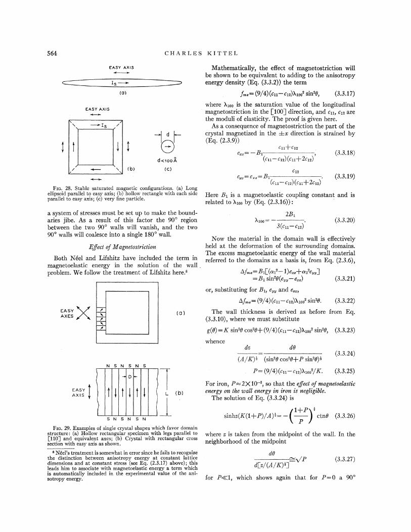
CHARLES KI TTEL
E:ASY AXIS
(a)
EASY AXIS
Mathematically, the effect of magnetostriction wi11
be shown to be equivalent to adding to the anisotropyenergy density (Eq. (3.3.2)) the term
f . (9/4) (crt —C12))ttpp2 sin'8, (3.3.17)
where X100 is the saturation value of the longitudinalmagnetostriction in the L100j direction, and c11, c12 arethe moduli of elasticity. The proof is given here.
As a consequence of magnetostriction the part of thecrystal magnetized in the &x direction is strained by(Eq. (2.3.9))
C11+C12
d«ooA(c)
e = —81(cl1 C12) (cl1+2C12)
e»= e» ——81(Cl1 C12) (Cll+ 2C12)
(3.3.18)
(3.3.19)
Fro. 28. Stable saturated magnetic configurations. (a) Longellipsoid parallel to easy axis; (b) hollow rectangle with each side Here 8& is a magnetoelastic coupling constant and isparallel to easy axis; (c}very Gne particle.
related to ) 100 by t',Kq. j2.3.16jj:a system of stresses must be set up to make the bound-aries jibe. As a result of this factor the 90' regionbetween the two 90' walls will vanish, and the two90' walls will coalesce into a single 180' wall.
Egect of cVageetostnction
Both Neel and Lifshitz have included the term inmagnetoelastic energy in the solution of the wallproblem. We follow the treatment of Lifshitz here. '
~1003(crt —C12)
(3.3.20)
~f„.=a,f(~, —1)e„+~2'e„„]=Bt sin'8(e„„—e„)
or, substituting for 81, e» and e„,(3.3.21)
Now the material in the domain wall is effectivelyheld at the deformation of the surrounding domains.The excess magnetoelastic energy of the wall materialreferred to the domains as a basis is, from Eq. (2.3.6),
Af, = (9/4) (c11—C12))trpp' sin'8. (3.3.22)
EASYAXES (a) The wall thickness is derived as before from Eq.
(3.3.10), where we must substitute
g(8) =E sin'8 cos28+ (9/4) (c11—c12))ttpp' sin'8, (3.3.23)
whence
N S N S N S(2/E) '* (sin'8 cos'8+P sin'8)'
(3.3.24)
P= (9/4)(c11—C12))ttpp /E. (3.3.25)
EASYAXIS
S N S N S N
For iron, P=2X10 ', so that the effect of mag22etoehastic
energy on the mull energy ie irorI, is negligible.The solution of Eq. (3.3.24) is
(1+Pp &
sinhs(E(1+P)/2) * = —I I
ctn8 (3.3.26)t. P )
FIG. 29. Examples of single crystal shapes which favor domainstructure: (a) Hollow rectangular specimen with legs parallel toL110j and equivalent axes; (b) Crystal with rectangular crosssection with easy axis as shown.
Noel's treatment is somewhat in error since he fails to recognizethe distinction between anisotropy energy at constant latticedimensions and at constant stress {see Eq. (2.3.17) above); thisleads him to associate with magnetoelastic energy a term whichis automatically included in the experimental value of the ani-sotropy energy.
Pd(./(a/E) &]
(3.3.27)
for P((1, which shows again that for I'=0 a 90'
where s is taken from the midpoint of the wall. In theneighborhood of the midpoint

PHYSICAL THEORY OF FE RROMAGNETI C DOMAI NS
domain may exist between the two halves of the wall.The angle variation is plotted in Fig. 26 for P= 2)& 10as for iron.
In Fig. 27 we give the approximate dependence of wallenergy and wall thickness on the crystalline anisotropyenergy. The exchange energy constant is taken as foriron: A=2X10 ' ergs/cm.
4. THEORETICAL DOMAIN STRUCTURES
4.1 Introduction
The size and shape of domains are not constantattributes of bulk ferromagnetic material but are func-tions of the dimensions and the orientation of theboundary surfaces of the crystals as well as of the stateof strain and of the magnetic field in tensity. Theessential reason why domains exist is that their forma-tion in general reduces the magnetic field energy whichwould be associated with a saturated magnetic con-Gguration.
The incentive that a given specimen has to formdomains will then depend on the magnitude of thedemagnetizing eBects associated with a single domainor saturated conGguration in the specimen. For example,all of the arrangements shown in Fig. 28 are stable.In (a) we have a long fine prolate spheroid with adirection of easy magnetization parallel to the shapeaxis; for sufficiently large values of the axial ratio thesaturated single domain configuration will have a lowertotal energy than an arrangement with domain struc-ture. That is, the decrease in magnetic energy accom-panying domain structure can be in this case less thanthe energy required to set up the requisite transitionlayers (Bloch walls) between domains.
In (b) we have a structure with four domains. Thereis no magnetic Geld energy here, since there are no polesanywhere (except for a relatively trivial pole strengthon the edges of the Bloch walls). The normal componentof the magnetization is continuous across the diagonalBloch walls shown as dotted lines, and this is thecondition that there be no poles on the walls. A crystalwith the domain structure discussed here has beenproduced by Williams and Shockley (1949).
In (c) we have a very fine particle, with a diameterof the order of (for iron) 100A or less. Here a singledomain structure is stable because the amount ofexchange energy required to set up a non-magneticconfiguration will exceed the magnetic energy of thesingle domain configuration. This inequality is onlyvalid for very small dimensions. There is considerableexperimental evidence for the stability of single domainstructure in small particles, as will be discussed in alater section.
The crystal shapes shown in Fig. 29 are, on the otherhand, favorable to domain structures along the linesindicated, provided always that the crystals are ofmacroscopic dimensions. We shall consider now theoptimum slab thickness D for a domain structure as
IX4JzLLI
DOMAIN WIDTH, D
FzG. 30. Energy of domain structure as functionof domain width D.
shown in (b) for a uniaxial crystal in the form of arectangular cylinder.
The area of Bloch wall is L/D per unit area of thecrystal surface, looked at from above, The wall energyis then
ol~=~wall+ ~magq
w =o„L/D+1.7I,'D,
(4 1 3)
(4.1.4)
0 +—
EASYAX!.S 1(
Xl-V-'V-~~
FzG. 31. Flu& closure domain configuration in uniazial crystal.
per unit, surface area, where o- is the surface energydensity of a Bloch wall. The magnetic field energyassociated with the parallel charged strips normal tothe paper is, according to Eq. (2.4.4),
wm, g——1.7I,'D
per unit surface area when both top and bottom surfacesare taken into account; here I, is the saturation magnet-ization. The variation of x,~~ and w „with D isplotted in Fig. 30. For large D the magnetic field energyis dominant, and for small D the wall energy is domi-nant.
The total energy per unit surface area is

566 CHARLES KITTEL
~I~PV'IWP&lfr~ll II'/ lQ/! lIlilIm II~~
)ieieeeeeeee I I ~ 5IISWI I M ~ ~ ~»
FIG. 32(h). Details of flux closure of "domain of closure" Q.
FiG. 32(a). Retouched photograph of domains of closurein Si-Fe crystal (Williams).
which is a minimum with respect to the domain widthD when
orBw/BD= —(o„L/D')+1.7I '=0,
D= [o.„L/(1.7I e)]'.
Therefore, the width is of the order of
(4.1.5)
(4.1.6)
D=[(2)(1)/(1.7)(1.7X10')']'*=10 ' cm (4.1.7)
for a crystal with X=1 cm. The domain width Dshould not be confused with the transition layer thick-ness 6 which is of the order of 10 ' cm.
The energy of the domain structure is
w =2[1.7I 'oL]'*-which is of the order of
(4.1.8)
w= 2[(1 7) (1.7X10')'(2) (1)]'=7 X 10' ergs/cm'. (4.1.9)
Since the crystal was taken with L=1 cm, the energyper unit volume is of the order of 7X10' ergs/cc,whereas the magnetic field energy density obtainingwith a saturated single domain structure would be ofthe order of I,'=10' ergs/cc. This shows that, quali-tatively, the formation of domairts has reduced the energy
of the system by a very considerable amountIf we had taken L= j.0 ' cm, as in a thin film, then
the energy density of the domain structure would alsohave been of the order of 10' ergs/cc, which is of thesame order as the magnetic energy density of thesaturated film. It becomes apparent that size plays animportant role in domain structure.
4.2 Flux Closure Domain Con6gurations
It is possible to devise a domain arrangement for therectangular slab just discussed which will have nomagnetic poles. Such an arrangement, first treated by
w,„,,=ED/2. (4.2.2)
The wall energy tends to increase the domain width,while the anisotropy energy tends to decrease the width.
The total energy is
w= (o L/D)+(ED/2) (4.2.3)
per unit area, and this is a minimum with respect tothe domain width D when
(Bw/BD) = (o„L/D')+(K/2) =—0. .
The condition for the minimum is then:
(4.2.4)
D= [2o„L/E]t (4.2.5)
FIG. 33. EGect of magnetostric-tion on domains of closure. Dottedcurve shows on exaggerated scalethe volume which would be occu-pied by the material in a domainof closure if the constraint exertedby the rest of the crystal wereremoved.
Landau and Lifshitz (1935) for a uniaxial crystal, isshown in Fig. 31. A similar structure (Fig. 32(a)) hasbeen observed by H. J. Williams on an iron crystal, inunpublished work. Iron is, however, cubic.
The "flux circuit" is completed entirely within thecrystal by means of the small triangular prisms on theupper and lower surfaces of the crystal. As shown inFig. 32(b) these domains of closure" transfer themagnetization lux from the upward-directed domainsto the downward-directed domains without any polesbeing formed. The absence of poles is the result of thecontinuity across the prism sides of the normal compo-nent of magnetization. We proceed to calculate theoptimum value of the domain width and the corre-sponding energy density. The wall energy per unit areaof the crystal surface is approximately
wwatt= &uL/D. (4.2.1)
The magnetic energy is zero, but the anisotropy energyis not zero (if the crystal is uniaxial). The volumecontained within the domains of closure is oriented in adirection of hard magnetization and involves an energyIC per unit volume, where E is the anisotropy constant.Per unit area of crystal surface on one side the volumein the domains of closure on both sides is D/2, so that

PHYSICAL THEORY OF FERROMAGNETIC DOMAINS 567
and the corresponding energy per unit area is
w =[2rr„I.E]'* (4.2.6)
The energy per unit volume is
fsetlLee s [20to%/~ 3 (4.2.7)
f=[(2)(2)(4X10s)/(1)]'=1.3X10s ergs/cc. (4.2.9)
For these values of the various constants the energyof the fiux closure con6guration Fig. 31 is somewhatlower than that of the simple slab con6guration Fig.29(b), but with increasing values of the ratio IC/I s
the domains of closure gradually open up and forE/I, '))1 the simple slab arrangement prevails.
Cubic Crystals with Positive Anisotropy Constant
In cubic crystals with the anisotropy constant E)0the directions of easy magnetization are the cube edges,so that in this case the direction of magnetization inthe domains of closure can be in an easy direction atthe same time that the magnetization in the basicslab-like domains (Fig. 31) is in another easy direction.It would appear then that the domain width will befree to increase almost without limit until the wholespecimen consists of four domains. Usually, however,this condition is not expected to occur because of theeGect of magnetostriction.
There will be in general a magnetostrictive energyassociated with the domains of closure. This resultsfrom the tendency of domains to change slightly inlength in the direction of magnetization, so thatdomains magnetized along different lines will- not fittogether smoothly except by the expenditure of elasticenergy in forcing the material to 6t together. Thedomains of closure, for example, may be regarded asbeing squeezed to join on to the basic domains, asshown in exaggerated form in Fig. 33.
In the case of a domain of closure the strain imposedby the basic domain structure is of the order of thelongitudinal magnetostriction constant happ as may beunderstood by referring back to Section 2.3. The elasticenergy density of the closure domains is then (approxi-mately)
If we arbitrarily substitute the approximate valuesof the constants for iron, and take the length I.as 1 cm,we have
D= [(2)(2)(1)/4X10s]''=3X10 ' cm (4.2.8)
FIG. 34. Domain branching nearthe crystal surface, as discussed byLifshitz. This structure would beexpected when the anisotropy ishigh, and related structures havebeen observed.
Numerically, for iron, with I.= 1 cm,
andD—[(4)(2) (1)/(10')j'=0.1 cm (4.2.13)
fq —[(2)(10')/(1)]'*=50 ergs/cc. (4.2.14)
General Case
The nature of the domain structure near the crystalsurfaces may actually be expected to be more compli-cated than the simple situations we have discussed.For example, I ifshitz has shown that the arrangementshown in Fig. 34 has under certain conditions a lowerenergy than the triangular prism arrangement. Thecomplete variational problem to find the nature of thedomain structure which minimizes the total energy hasnot been solved; instead we assume certain types ofdomains on the basis of physical insight, and thenminimize the energy with respect to one or moreadjustable parameters.
In general it is probably a fair approximation tosuppose that the total energy consists of two parts:one part being the energy of the Bloch walls, m «, and
fel 2cll)tloo i (4.2.10)
which is of the order of 500 ergs/cc in iron.For the situation in this type of cubic crystal we
have as the domain width
D= [40wL/cllX100 j (4.2.11)
and as the energy density of the domain structure
fdo [&wert%os IL] (4.2.12)FlG. 35. Powder pattern on hexagonal face of cobalt
single crystal (Williams).

CHARLES K I TTEL
30 KVELECTRONS HEXAGONAL FACE
PHOTOGRAPHICPLATE
FIG. 36(a). Arrangement for detecting surface magnetic6elds by electron scattering.
~mali=& L/D (4.2.15)
where I. is same characteristic average length, while
w,„~,„y„,i g(D)—— (4.2.16)
is some function of the slab width. The nature of thedependence is determined by the structure of thesurface domains. The minimum energy occurs for theslab width Do for which
(& I-/Dos)+g'(Do) =O. (4.2.17)
It is important to appreciate the fact that thedomain structures of most crystals fall naturally intotwo classifications, a superficial domain structure whichis connected with the local details of Aux closure on thecrystal surfaces, and the basic domain structure runningthrough most of the volume of the sample. The super-ficial structure very often assumes a highly complicated
the other part, m, &„f,„,t, the local energy associatedwith the outer surfaces of the crystal. We may supposethat for slab-like domains
pattern, such as shown in Fig. 8, whereas the under-lying basic structure in single crystals is believed to befairly simple in most cases (Fig. 7).
The width of the basic structure is determined bythe surface energy density g(D) of the superficial struc-ture and the wall energy o.„.The nature and scale ofthe superficial structure depends on the relative valuesof magnetic, anisotropy and magnetoelastic energiesat the crystal surface.
In cobalt the anisotropy energy is dominant and asa result the Aux closure is incomplete. A typical domainpattern obtained on a hexagonal face of a cobalt crystalis shown in Fig. 35. L. H. Germer (1942) has confirmedby electron beam methods the existence of strong localmagnetic fields of the order of 10,000 oersteds just atthe hexagonal face of a cobalt crystal. 30 kilovoltelectrons scattered from a hexagonal face produce on aphotographic plate an exceedingly complex pattern(Fig. 36) made up of curves or arcs interlaced in elabo-rate fashion. Iron and nickel crystals show no similarphenomenon, and it may be inferred that the magneticfields are very weak, as would be expected from domainarrangements in which the Aux circuit is closed insidethe crystal. The results for cobalt, of course, suggestthat the Qux circuit is not closed inside the crystal, inthis case, and this conclusion is in agreement withtheoretical expectation.
In the extreme case of very high anisotropy energyone may expect the domains to be slab-like over their
~ ~ I" sss I IR6IBSl
xiii
goal, %!5!Il+
NilII ~
,,BllPlf)'„
K,;
Fro. 36(b). Results obtained in scattering of electrons from the hexagonal face of a cobalt single crystal (Germer, 1942).

P H YS I CAL THEORY OF F E RROMAGN ET I C DOMAINS 569
entire extent, and there will then be no special super-ficial domains. In the other extreme, where the ani-sotropy and the magnetostriction are both zero, allsemblance of a discrete domain structure disappears,and the requirements of Aux closure are over-riding,except when signi6cant changes in direction of magnet-ization on a scale of 10 ' cm is required —in which casethe exchange energy must also be considered. Twopossible domain structures for this case are shown inFig. 37. The domains have swollen so that each domainoccupies a large part of the volume of the crystal.This limiting case may be expected to set in when thethickness of a Bloch wall becomes comparable with thecrystal dimensions. For a thickness of 10 ' cm, theanisotropy energy must be of the order of only oneerg/cc. It is barely possible that we are approachingsuch a situation in supermalloy in thin tape form(Bozorth, 1948).
%le have not discussed in this section the question ofdomain structure in the presence of applied magneticfields. The calculations proceed along the same generallines as above, and for details the reader may consultthe papers by Neel (1944c) and Kholodenko (1947).Hates and Neale (1949) have confirmed experimentallythe predicted dependence of domain width on appliedmagnetic Geld in the [011$direction in silicon iron.
S. EXPERIMENTAL STUDIES OF DOMAINS
In the preceding sections of this review the generaltheoretical basis of the structure of ferromagneticdomains has been described in considerable detail. Wenow discuss some aspects of the experimental basis ofthe theory.
There are a number of diGerent sources of experi-mental information concerning domain structure. Byfar the most important source, with regard to funda-mental understanding, is that of magnetic powderpatterns. The powder pattern technique was introducedby Bitter, Elmore and others, and finds its highestdevelopment in the definitive papers of Williams,Bozorth, and Shockley (1949) and Williams and Shock-ley (1949). The principle of the method is analyzed inSection 5.1, and a selection from the experimentalresults is discussed in Section 5.2. For further detailsthe reader is referred to the papers of Williams andhis collaborators.
Other experiments on domain structure include:
(a) Scattering of electron beams (Germer, 1942; Marton, 1948);(b) Depolarization of beams of polarized neutrons (Surgy,
Hughes, and %allace, 1948);(c) Sixtus and Tonks (1933) domains in stressed wires;(d) Dependence of magnetostriction and magnetoresistance on
applied field and stress (Bozorth, 1946).
(a)
Fxo. 37, Theoretical possibilities for domain structures in thelimit of zero anisotropy energy.
investigation. The liquid contains a colloidal suspensionof a fine ferromagnetic powder, which is usuallymagnetite with a particle size of the order of one micron.
We are now going to show that a great local concen-tration of particles in the colloid 61m is expected as aresult of variations in magnetic Geld at the edge of aBloch wall,
The magnetic particles are acted on by a force whenin the presence of an inhomogeneous magnetic field,and are drawn to the points on the surface of the samplewhere the magnetic 6eld intensity is highest. Actually,it appears as if the particles are in thermal equilibrium,so that the density distribution of particles in the liquid
32
28
24c~V)
0 20I-OZ
16
cA2.'
t2CI
5.1 Magnetic Powder Pattern Technique
The magnetic powder pattern technique consists inthe application of a thin liquid layer to the carefullyprepared surface of the ferromagnetic sample under
03 4x = &H/yT
Fzo. 38. Plot of particle density function (sinhx)/x vs, parameterx=pH/kT, where p is the magnetic moment of a single particle.

570 CHARLES K I TTE L
I?
Il'iI
particle makes with the field H. Here we assume thatthe particle has a permanent magnetic moment; also,we neglect particle-particle interactions. On averagingp(H, 8) over all angles 8, we get the mean value
1 t" &pH cos8ip(H) =—
~l exp~ — ~2z- sin8d8,kT )
MAGNETIZATION NOR MAL TO SCRATCH= (sinh(iiH/k T)/(liH/k T)). (5.1.2)
~ ~ ~
~ ~ ~
MAGNETIZATION PARALLEL TO SCRATCH
FIG. 39. Determination of the magnetization axis bymeans of the scratch technique.
is given by the Boltzmann distribution function. Thatis, the particle density p(H) at a point where the fieldintensity is H is related to the density p(0) where thefield is zero by the relation
p(H, 8) =p(0) exp(liH cos8/kT), (5.1.1)
where 8 is the angle the magnetic moment p of the
Fzo. 40. Drawing of colloid pattern on a (100) surface with aset of scratches parallePto the L010) axis. The magnetization isparallel to L010$';.in~regions where the scratches do not appear,and is parallel to L001j where the scratches are visible,
A plot of the function p(H) = (sinhx)/x, wherex=iiH/kT, is given in I'ig. 38. It is seen that theparticle density rises sharply when x is of the order of3 or greater; that is, when pIJ)3k'l. Taking, as arough estimate, I, for the particle as 400 and theparticle volume as 10 " cc, we must have a fieldvariation
3(1.4X10 ")(3X10')H) (3kT/ii) = =3X10 4 oersteds
(4X 10s)(10-»)
in order that an appreciable density variation mayoccur. For a particle volume of 10 "cc, correspondingapproximately to a diameter of 0.1 micron, the magneticfield variation must exceed 0.3 oersteds.
Now there are field variations at the surface of aferromagnetic crystal greatly exceeding 0.0003 or 0.3oersteds. On a crystal surface with a Aux closuredomain configuration, as in Fig. 31, there will be localfields along the lines where the plane of the Bloch wallsintersect the surface. As the change in spin directionwithin a Bloch wall occurs in the plane of the wall, it isevident that if we cut oG the wall, as we must do at thecrystal surface, then the spins in the wall will have acomponent of magnetization normal to the crystalsurface. ' That is, there will be a line of either S or 5poles wherever a Bloch wall comes out on the surfacesof the specimen. These lines of free poles produce amagnetic field which is quite adequate for the purposeof forming a dense line of colloid particles. As a verycrude estimate, we may consider the perpendicularintersection of a wall with the surface of a crystal ofiron to produce a pole density I, on a strip about 10 'cm wide, corresponding to a linear pole density
g= (1700)(10 ') =0.02 gauss/cm.
At a distance of one micron from the wall this producesa field H= 2g(r = 2(0.02)/10 '=400 oersteds.
This estimate shows that the field intensity due tothe edge of a Bloch wall is several orders of magnitudegreater than that needed to form a dense line of colloidparticles. Actually our estimate must be corrected forthe p*-eGect discussed in Section 2.4. That is, we mustallow for the fact that the line of poles rests on perme-able material, with permeability p*=1+2rrI.s/E. Thesolution to the boundary-value problem of the field dueto a line of poles on a uniform permeable half-plane
'gee Fig. 23,

PHYSICAL THEORY OI FERROMAGNETI C DOMAINS
20,000
12.000
8,000
4,000
FIG. 41. Magnetizationvs. displacement of the 180'Bloch wall and patternsshowing the Sloch wallin three different positions(Williams and Shockley,1949).
0
4,000
8,000
12,000
16,000
20,0000 20 40 60 80 )00DISTANCE IN MM ON FILM
shows that the 6eld in the air is reduced with respectto the free space field by the factor 2/(1+p~), which isequal to 0.047 for iron. The corrected field intensityat one micron distance is about 20 oersteds, which isstill ample for the formation of a dense line of colloidparticles, as is actually observed.
The theory of line formation has also (Kittel, 1949b)been developed for the case of colloid particles whichare not permanent magnets, but which are permeablespheres, as is probably more often the case.
Particle concentration will also occur, and often to agreat degree, in cases where there is not a Aux-closuredomain configuration, but where domains themselvescome to an abrupt end on the crystal surface. This isexpected to occur in materials of high anisotropy energy,and is in fact commonly found in cobalt and on a (111)plane of iron.
We have shown that large local concentrations ofcolloid particles occur on the faces of ferromagneticspecimens. These concentrations may be observed underan optical microscope, when the specimen is suitablyilluminated.
5.2 Selection of Results of Powder Pattern Work
We discuss now some of the results which haveemerged from powder pattern studies. We shall treatthese three topics:
1. Determination of direction of magnetization by scratchtechnique (Williams, 1947)
2. Correlation between magnetization changes and boundarydisplacement {Williams and Shocl~ley, 1949)
3. Dagger blade domains around cavities and crystal imper-&ections (Williams, 1947).
5.Z.1. 5cratch TechrIique
In the absence of a magnetic field the direction ofmagnetization of the domains will be along the axes ofeasy magnetization of the crystal. In an iron crystalthere are three axes of easy magne tization, thethree being mutually perpendicular and along the cubeedges.
In interpreting a powder pattern we wish to knowthe direction of magnetization in all parts of thepattern. We may determine the axis of the magnetiza-tion in some important cases by what is known as thescratch technique; and the setose is then determined byobserving the expansion or contraction of the domainwhen acted on by an external magnetic 6eld parallel tothe domain axis.
The scratch technique may be understood by refer-ence to an (001) surface of an iron crystal. The preferredaxes are parallel to [100] and [010]. If we make afine scratch on the surface parallel to [100], we shall
get colloid deposition on the scratch from domainsparallel to [010], but the scratch will not collectcolloid particles from domains parallel to [100].Thatis, colloid collects when the magnetization crosses thescratch, but not when the magnetization is parallel tothe scratch. The situation is made clear by Fig. 39.It is the leakage Qux that attracts the colloid particles,and there is no leakage when the magnetization isparallel to the scratch.
A drawing of a domain pattern demonstrating theeffect is shown in Fig. 40, which was obtained byWilliams (1947).

8 IISI' ~ l
.~ «?
?l'«:4 t.'
jj ss r I .'««?5'
'saIj I te
«y-r ~
mgj
Im Its
'%LQ4'j'''""''"""""i~ywiiij'j"'
i'i%'.-'
'" ""'::««» "'ll?iiPii ~i SISs
. %!F ?l?
jill S g?sih't
4:,:::.Hill «
= ""Ran'
I I I I!
I IQg ?H«
159' -' '-ltL-'~~
''ll l, ~m~ I le 'b~ I l'
«l
Ji':::i?rJ' II-.m': . &.
l?«
;:--~l]E;-
:,.':;:?~: .y
IK
«'?""-'.
,, ;,c, j:;:.:goal I I 8%e ~ jS Sl:.:8 Ihk'ak'it I„.rs LmlIkkr
ss
I@I?,„. sr?sJi II ~ I P. ~.-:.a",.A, II NII"t'?""
,.c;8
J I SII II '.
«?.st" . j~::;:::::,:::;.:::-:':::::::::.'::::3:.:.
' 5" ~~"'~""'-':.:"~:;:::::::::,:::::,-.,)P!.,":::,','««ll im'
.,p'A ~
?u?' ~ o. I I r«. :;.+ I l:,.~l' '?
~r?I?'y. J' 'i '
l l ~
IIJ
' '.s
iud 8'l~l K:-'::=:-:::=-."-':::&l ~::::':::::.:k::~&, ~..9 I rj
M I Sl I554cm
FIG. 42. Domain structure around cavities: the structure in the left-hand drawing was predicted by Neel (1944b) on energyconsiderations; the predicted pattern was found experimentally by Williams (1947).
5.Z.Z, Correlation betzeem 3Eagnetisatioe Charges aedBoundary Di sP/acemeut
In Fig. 11 we have given a sketch of the simpledomain structure found by Williams and Shockley(1949) in a single crystal of iron (containing a smallamount of silicon). Reversal of the magnetizationcircuit shown in Fig. 11 (a) proceeds by the formationand movement across the crystal of the Bloch wallshown in (b) in the form of a rectangle. The rectangleexpands or contracts in size according to the relativeamounts of Aux carried clockwise or counterclockwise.
If the wall shown goes straight through the crystal,then we would expect to find a linear relationshipbetween the change of magnetization and the displace-ment of the Bloch wall relative to the side of the crystal.This result is verified by the measurements shown inFig. 41. This experiment must be considered as one ofthe most fundamental experiments in the field offerromagnetism, as it shows that there is a directproportionality between wall displacement and net Aux.
5.Z.3. Domain Structure Around Cavities
Noel (1944b) pointed out that the presence of acavity in the magnetic material included in a domainwill give rise to a considerable amount of magnetostaticenergy because of the formation of E and S poles onopposite faces of the cavity. He suggested that a localdomain structure such as that shown in Fig. 42 would
form around the cavity, with a reduction in the totalenergy. The Keel structure has the effect of distributingthe poles along the curved portions of the boundaries.As the domain elongates the magnetostatic energydecreases and the wall energy increases, and thatstructure occurs for which the sum of the two energiesis a minimum.
Williams (1947) has found domain patterns of theexpected type around holes in a silicon iron crystal.
Measurement of the ratio of length to width of theWeel domains offers a possible experimental method fordetermining 0. , the surface energy density of a Blochwall. Values estimated in this way are of the correctorder of magnitude.
6. MAGNETIC PROPERTIES OFSMALL PARTICLES
If the specimen is cooled from above the Curie pointin field-free space, it is a matter of common observationthat the demagnetized state is the stable state in largeferromagnetic crystals. In the demagnetized statethe domains are oriented so that the magnetic Aux
circuit lies almost entirely within the specimen, and theoverall magnetic moment of the specimen is approxi-mately zero.
As the dimensions are diminished, the relative contri-butions of the various energy terms to the total domain
energy are changed, and surface energies become moreimportant than volume energies. The surface of the

P H YSI CAL THEORY OF F ERROMAGNETI C DOMA I NS 573
transition layer (Bloch wall) between domains is asurface energy, while the energy in the magnetic field(magnetostatic self-energy) is a volume energy. Whenvery small dimensions are reached, there will be a pointat which it is favorable energetically to do away withthe domain walls, so that the whole specimen becomesone domain and acts as a permanent magnet. This wasfirst predicted by Frenkel and Dorfman (1930), al-though in their note the surface energy of the boundarybetween domains is over-estimated by a factor of theorder of 50, leading to much too high values of thecritical dimensions for single domain behavior. Im-proved and corrected calculations were first publishedby Kittel (1946); followed by Neel (1947a) and Stonerand Wohlfarth (1947; 1948).
Experimental evidence of the intrinsic permanentmagnetization of small ferromagnetic particles wasdemonstrated first by Elmore (1938, 1941), althoughthe eAect had been suspected earlier, as for example byAntik and Kubyschkina (1934), on the basis of evidenceregarding the magnitude of the coercive force. The gen-eral agreement of experiment with theory in the smallparticle area is not as good as might be desired, but inmany cases it seems pretty clear that the theory is onthe right track. Complications due to agglomeration inactual materials have not been discussed adequately.
The single domain behavior of small particles prom-ises to be of great practical importance in connectionwith materials for permanent magnets. This is becauseof the very high values of the coercive force which it ispossible to obtain with single domains.
Similarly, single domain behavior is expected in verythin films (Kittel, 1946), and experimental evidence forthis is suggested by the recent work of Origo and Pizzo(1948) on the Barkhausen effect in thin films of Fe, Ni,and Co. They find that the Barkhausen eGect disap-pears when the thickness of the films is reduced to10 ' cm, in good agreement with the theoretical valueof the critical thickness for single domain behavior.
radius R, the energy is
w= fV = (1/2)(4n/3)'R'I ' (6.1.2)
and is approximately 24)&10' ergs for X=1 cm and24)&10 "ergs for 8=10 ' cm.
We now must consider the energy of simple arrange-ments of domains. If the anisotropy is low it appearsreasonable to take the circular configuration shown inFig. 43(a) as the most favorable Aux-closure configura-tion, whereas if the anisotropy is very high we mayexpect a situation as shown in (b) for a cubic crystaland as shown in (c) for a uniaxial crystaL These threecases will now be treated individually.
6.1.1 I.ow AmsotropyL
The energy here is largely in the form of exchangeenergy. Consider the spins on a circular ring of radiusr. There are 2~r/u spins on the ring, where u is thelength of a side of the unit cell. The total change inangle in going around once is 2x, so that the angle ybetween successive spins is
q =u/r,and
w„;„~=(1/2) J(u/r)2(2irr/u) = vrJu/r,
(6.1.3)
(6.1.4)
by Eq. (2.1.5), with S=1. Now consider the spheremade up of circular cylinders (Fig. 44), each one unitcell in thickness. The number of rings in a cylinder is(2/u)(R' —r')«, so that
(a3
FiG. 43. Types of simple domain arrangements in a smallsphere: (a) Applies for low anisotropy, (b) for high anisotropyin a cubic crystal, and (c) for high anisotropy in a uniaxial crystal.
6.1 Critical Particle Size for SingleDomain Behavior
w i 2'J(R——2 r2)«/r, —
~Bw,„i„„,= (2m J/u) [(R'—r')«/rjdr
(6.1.5)
f= 'IHIP =2~I '/3- (6.1.1)
for a sphere. The numerical value is approximately6X10' ergs/cc in the case of iron. For a sphere of
We shall consider a small spherical ferromagneticparticle of radius R; it is supposed for the sake ofconcreteness that the particle is a single crystal. Weare interested first of all in the critical particle size forwhich the energy of the single domain configuration islower than the energy of configurations in which thereis a domain structure tending towards Qux closure.
The energy density of the saturated single domaincon6guration is in the form of magnetostatic energy,and is equal to, from Eq. (2.4.3),
=(2%rJR/u)DB(2R/u) —1j (6.1.6)
or, per unit volume,
f,.= (3/2) (J/uR') )le(2R/u) —1]. (6.1.7)
This energy density depends on the size of the sphere.
rFn. 44. Decomposition of sphere intocircular cylindrical shells.

CHARLES KITTEL
CRYSTALAX IS
Fxc. 45. Geometrical situation forthe calculation of the coercive forceresulting from magnetocrystalline ani-sotropy, for the case of a uniaxialcrystal. ~uiall 2&m~+ ~ (6.1.9)
For an iron particle with J'=10 ' cm we have m, ll—14X10 "ergs; but the value of the critical radius isabout 0.7X10 cm, since
possible for the critical radius to exceed appreciablythe wall thickness. When this condition is satisfied thecritical radius may be calculated by use of the modelshown in Fig. 43(b). The energy here is essentially inthe form of wall energy and is equal to
f.~= 0.8X 10' ergs/cc.
The values of m may be compared with those calcu-lated following Eq. (6.1.2) for the saturated configura-tion. It is seen that the Aux-closure configuration has
by far the lower energy when the radius is 1 cm, butwhen the radius is 10 ' cm the saturated configurationhas the lower energy.
Thus for sufficiently small particles the saturatedconfiguration has a lower energy than the Qux-closureconfiguration. The critical radius E, is given by
(1/2)(47r/3)'Ec'I'= (irJR,/o) Lln(2R, /u) —1j, (6.1.8)
and is approximately inversely proportional to thesaturation magnetization. The value of the criticalradius for iron is ~10 ' cm.
An expression practically equivalent to Eq. (6.1.8)was first given by Neel (1947a).
6.1.2 High Anisotropy, Cubic Crystal
In the preceding calculation the anisotropy energyassociated with the Qux-closure configuration was neg-lected in comparison with the exchange energy; this isjustifiable if the critical radius is appreciably smallerthan the thickness of a Sloch wall in the material.This follows because the anisotropy and exchangeenergies are equal in a Bloch wall, but the exchangeenergy will be dominant if the change in spin directionis constrained to take place in a distance less than thewall thickness.
But if the anisotropy energy is high it may be
ThsLE Il. Maximum coercive forces of small particles due tovarious causes. (Complete orientation assumed; packing effectsneglected. ) T=2X10"dynes/cm'.
ExpressionFeCoNi
Anisotropy
2E/I,500
6000135
Shape
2m-I,10,7008,8003,150
Internal strain
AT/I.600600
4000
Using the value I/a=2X10 ' ergs/cm for iron fromEq. (2.1.18), we have
(a) 8=1 cmm„=1,3X10 4 ergs
(b) 2=10 ' cm
m.~=23X10 "ergs
which leads toR.=9o/4irI, '. . (6.1.12)
This is identical with Eq. (6.1.10). For MnBi we mayestimate
L20/(600)'j 4X 10—' cm,
while the wall thickness is of the order of 8=2&10 'cm, so that in this case the basic assumption b/R, ((1of the calculation is valid.
Similar calculations for fine wires and thin films, aswell as for fine particles, were given by Kittel (1946).
6.2 Coercive Force of Small Particles
We have just seen that the formation of domainboundaries is energetically unfavorable in the case ofsuf5ciently small particles. Now in the absence ofdomain boundaries changes of magnetization cannotproceed by the "easy" process of boundary displace-ment (Fig. 5) but must rather proceed exclusively bythe "hard" process of rotation of the total magneticmoment of the particle (Fig. 16).
When we have ruled out the possibility of boundarymovement we may obtain large increases in the coerciveforce by means of increasing the effective anisotropy ofthe specimen —that is, by making it as difficult aspossible to rotate the magnetization of the domain as awhole. This was pointed out Grst by Kittel in 1946.In order to reverse the direction of magnetization in asmall particle it is necessary that the magnetic energyacquired by the particle in the external magnetic Geld
be greater than the internal energy tending to preventrotation of the domain direction. The effective internalanisotropy will be high if the magnetocrystalline ani-sotropy energy is high (Kittel, 1946), or if the shape of
R,= (9/4~) (o. /I, ') (6.1.10)
as follows from equating Eq. (6.1.9) with Eq. (6.1.2).This value for the critical radius is less than the wallthickness so that the calculation is not applicable. Ifthe anisotropy energy were increased by a factor of 10or more, then the calculation would be applicable.
6.1.3 High Anisotropy, IIniaxial Crystal
For the model shown in Fig. 43(c) the energy balanceis roughly given by
(1/2) (1/2) (4n/3) 'E.'I 2+mrE, 'o= (1/2) (4s/3)'R'I ' (6.1.11)

PH YSI CAL THEORY OF FERROMAGNETI C DOMAINS
the particle is very elongated (Neel, 1947b), or if asevere strainis applied in an anisotropic manner (Stonerand Wohlfarth, 1947). The first of these causes is mostprobably responsible for the highest observed values ofthe coercive force, namely, 12,000 oersteds in MnBiand 20,000 oersteds in FePt.
We discuss now the coercive force due to each ofthese three causes separately. It is assumed in all casesthat only single domains occur. We first treat the caseof a single particle, and later consider the modificationsintroduced when a collection of particles are packedtogether densely. Table II compares the values of thecoercive force of fine particles of Fe, Co, and Ni, ascalculated for various mechanisms.
12,000
10,000
LLJ
O 8PPOx
6,ooo
04,ooo
0 2,000
00 2 4 6 8 10 12 14 16 I8 20
AXIAL RATIO
I'IG. 46. Coercive force in an iron particle due to anisotropy ofshape, as a function of the axial ratio of the particle.
fx=Ki sli18, (6.2.1)
according to Eq. (2.2.2); 8 is the angle between thecrystal axis and the direction of magnetization. Themagnetic energy density is, for an applied magneticfield Ho parallel to the crystal axis,
f„.,=HpI, cos8 (6.2.2)
where the choice of sign was made to correspond to afield direction opposite to the projection of magnetiza-tion on the crystal axis (Fig. 45).
The total energy is
f=Ki'sin'8+HpI, cos8 (6.2.3)
6.2.1 Coercive Force Resulting from MagnetocrystallineAnisotropy
The anisotropy energy density in a uniaxial crystalmay be written, to the first order,
usually oriented at random. In this case Neel (1947a)has shown that for cubic crystallites oriented at randomthe coercive force for the average hysteresis loop is
(H,)~„=0.64K/I, (6.2.10)
for E&0. This is about 160 oersteds for iron. If weassume the same factor for cobalt, which is uniaxial,we get (H,)~„=2500oersteds.
6.Z.Z Coercive Force Resulting from Anisotropyof Particie Shape
We suppose that the particle is in the shape of aprolate spheroid. We restrict the discussion to the case
and is a minimum with respect to 0 when e= 0 0-
orBf/88=0=2Ki'sin8cos8 —HpI, sin8 (6.2.4)
Hp=(2Ki'/I, ) cos8 (6.2.5)
which is a maximum (and therefore equal to thecoercive force) when 8=0. Thus,
H, =2Ki'/I, . (6.2.6) e =90' 0-
This result also applies to the case of cubic crystalsif the field is applied along a $001$ direction. For asmall 8 the anisotropy energy is
fK=K18
according to Eq. (A.3). The total energy is
f=Ki8'+HpI, cos8,
which is a minimum with respect to 8 when
8f/88=0=2Ki8 HpI sin8—which, in the limit 0=0, gives
H, =2Ki/I,
(6.2.7)
(6.2.8)
(6.2.9)
e =45' 0-
0H
2rrIS
Pro. 47. Magnetization curves for elongated particles, for theapplied field parallel, perpendicular, and at 45' to the long axis
In actual samples of powder materials the grains are of the particle.
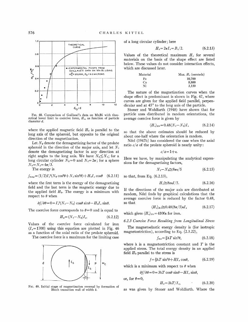
576 CHARLES Kl r rEL
I.O
THFORETICALCURVE
of a long circular cylinder; here
H, = 2prI, =8,/2. (6.2.13)08
069ux
U0.4
~ = EXPERIMENTAL POINTS FROMGUILLAUD S DATA ON Mn Bi. USING
Hc = 20 000 ~ dp = 9.0 MICRON S MatenalFeCoNi.
Max. H, (oersteds)
10)7008,8003,150
Values of the theoretical maximum H, for severalmaterials on the basis of the shape eAect are listedbelow. These values do not consider interaction eGects,which are discussed later.
0.2
00
dp d
10 '12
FIG. 48. Comparison of Guillaud's data on MnBi with theo-retical lower limit to coercive force, H„asfunction of particlediameter d.
where the applied magnetic field Hp is parallel to thelong axis of the spheroid, but opposite to the originaldirection of the magnetization.
Let N p denote the demagnetizing factor of the prolatespheroid in the direction of the major axis, and let N~denote the demagnetizing factor in any direction atright angles to the long axis. YVe have Np&N~, . for along circular cylinder Np=0 and N& ——2m,. for a sphereÃo= 1Vc=47r/3.
The energy is cVg—lIt'p=8v e/5 (6.2.15)
The nature of the magnetization curves when theshape e8ect is predominant is shown in Fig. 47, wherecurves are given for the applied field parallel, perpen-dicular and at 45' to the long axis of the particle.
Stoner and Wohlfarth (1948) have shown that forparticle axes distributed in random orientations, theaverage coercive force is given by
(H,)g, =0.48(1V(—cVp) I, (6.2.14)
so that the above estimates should be reduced byabout one-half where the orientation is random.
Neel (1947b) has considered the case when the axialratio c/a of the prolate spheroid is nearly unity:
c/8= 1+s.Here we have, by manipulating the analytical expres-sions for the demagnetizing factors,
f„„=(1/2)I, '(Xp cos'8+Nq sin'8)+HpI. cos8 (6.2.11) so that, from Eq. (6.2.13),
where the first term is the energy of the demagnetizingfield and the last term is the magnetic energy due tothe applied field Hp. The energy is a minimum withrespect to 0 when
Bf/88=0=I, '(X~ Np) cos8 sin8 ——HpI, sin8.
The coercive force corresponds to 0=0 and is equal to
H.= P~—&o)I' (6.2.12)
Values of the coercive force calculated for iron(I,=1700) using this equation are plotted in Fig. 46as a function of the axial ratio of the prolate spheroid.
The coercive force is a maximum for the limiting case
i[
I „p ~
fz,I'
H, 87reI/5— (6.2.16)
If the directions of the major axis are distributed atrandom, Neel finds by graphical calculations that theaverage coercive force is reduced by the factor 0.48,so that
(H,)g„—0.48(8v./5) eI,
which gives (H.)g,=4100e for iron.
(6.2.17)
6.Z.3 Coercive Force Resulting from Longitudinal Stress
The magnetoelastic energy density is (for isotropicmagnetostriction), according to Eq. (2.3.22),
f,= ssXT sin'8, (6.2.18)
f= sPXT sin'8+HI, cos8,
which is a minimum with respect to 0 when
Bf/88=0=3XT cos8 sin8 —HI, sin8,
or, for 0=0,
(6.2.19)
where X is a magnetostriction constant and T is theapplied stress. The total energy density in an appliedfield Hp parallel to the stress is
H, =3XT/I„ (6.2.20)FH;. 49. Initial stage of magnetization reversal by formation of
Bloch transition wall of width 8. as was given by Stoner and Wohnarth. Where the

PHYSICAL THEORY OF FERROMAGNETIC DOMAINS
stress is due to internal strains a reasonable upper limitto the stress is taken by these authors to be 200 kg/mm',or 2X10" dynes/cm'. The maximum coercive forcesfor iron, nickel, and cobalt are then 600, 4000, and 600,respectively.
6.ZA DePenderice of the Coercive Force ori, Particle Size
It is an experimental fact that the coercive forceincreases rather gradually as the particle size is de-creased. The variation of coercive force is probablymore gradual than can be accounted for by the disper-sion in the dimensions of the particles in any sample.The experimental results of Guillaud (1943) on finepowders of the compound MnBi are shown in Fig. 48;it is seen that there is a considerable variation incoercive force H, over the range of diameters from 3 to100 microns.
A rough theoretical explanation of this variation hasbeen given by Kittel (1948), using a model (Fig. 49)which applies to spherical particles of high anisotropymaterial.
We consider a small sphere magnetized to saturation;when the field H, is applied it is supposed that adomain wall forms as shown in Fig. 49. In this positionthe energy balance is given approximately by theequation
o(~p /4) =H,I, (m'p 8/8)+iI U(5/2d). (6.2.21)
Here 0- is the surface energy density of a Bloch wall,
p is the wall diameter, and 8 is the wall thickness; U isthe volume of the sphere. The term on the left approxi-mates the energy of formation of the wall; the firstterm on the right approximates the magnetic energy ofthe wall material in the applied field H„while thesecond term on the right is a crude estimate on dimen-sional grounds of the change in the magnetic self-energyof the sphere.
Using the geometrical relation p'=48d, we may writeEq. (6.2.21) in the form
H,/H;=1 —(d/d, ),where H,"=2o/8I, and do ——2. 4o/I 2 Now, from th.etheory of the Bloch wall, o (EkT,/u) & and
(kT,/Eu)', so that H," 2E/I„ in agreement withthe value obtained from domain rotation. For MnBi,we calculate H,"=40,000 and dp 7&&10 ' cm. Theestimated value of dp is uncertain by an order of magni-tude, because of the crudeness of the estimate of thechange in self-energy of the sphere. The theoreticalcurve plotted in Fig. 48 was fitted to the data usingH,"=20,000 and dp ——9&10 ' cm.
The present theory may be regarded as setting anapproximate looser limit to the coercive force as afunction of particle size—a lower limit because it is notclear without very detailed calculation that the situa-tion pictured in Fig. 49 actually corresponds to themaximum energy barrier for wall formation.
On this model the particle diameter for H, =H,"/2
10
Vz
x 104
X~A
0-UZ
IX4J
ILI
X 10
O
1010"7
27/ IS
10 6 10 10 4SURFACE ENERGY OF WALL / (SATURATION MAGNETIZATION) IN CM
FIG. 50. Approximate upper limit to particle diameter formanifestations of single domain behavior.
is given by
D= do/2 = 12o/Ia . ' (6.2.23)
This relation is plotted in Fig. 50; the coordinatescalculated for Fe, Co, Xi, and MnBi have been plottedas short lines, so as to suggest the approximate natureof the calculation. The particle diameter calculatedfrom Eq. (6.2.23) may be considered as an approximateupper limit for pronounced manifestations of singledomain behavior. The relation assumes a high aniso-tropy energy, so that it is not really applicable to nickeland iron.
1000
PRESSED PONDER70 Fe-30 C0
800
0600
~a0x
OIX0 400LLJ
0
0u 200
00 0.25 0.50
PACKING FACTOR0.75 &.00
FIG. 51. Effect of density of packing on the coercive force of70 Fe 30 Co 6ne powder magnets, according to Weil (1947).The packing factor is the fraction of the volume of the magnetwhich is 6lled by magnetic material.
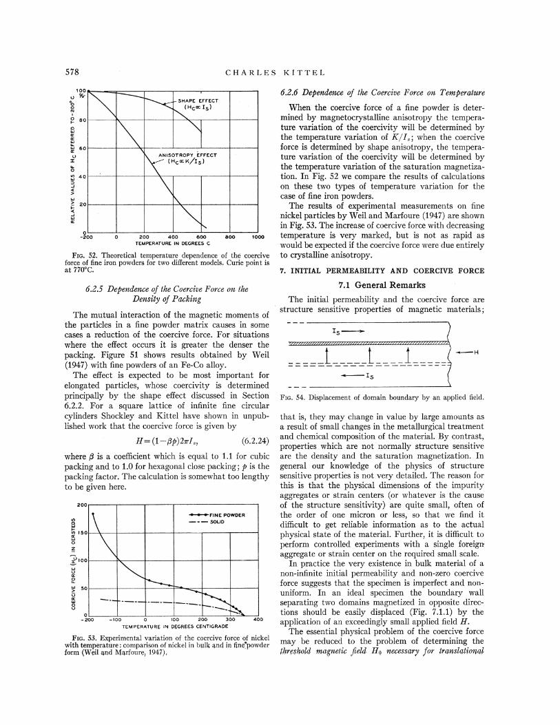
CHARLES K ITTEL
$00-v 9o
OO
I
0 eoCILJK
LsJ
60vx0'Q 40
20
4JlK
0-200
SHAPE EFFECT
200 400 600TEMPERATURE IN DEGREES C
800 1000
Fzc. 52. Theoretical temperature dependence of the coerciveforce of fine iron powders for two different models. Curie point isat 770'C;
200
IAOLLJ
u) IQOLLJ0Z
IOO
vLL'
0so
vLL.'
0v0
» 200
:FINE POWDER—-—SOUD
- IOO 0 IOO 200 300TENIPFRATVRK IN PMRK4$ CFNTIGRADE
400
FIG. 53. Experimental variation of the coercive force of nickelwith temperature: comparison of nickel in bulk and in tine"powderform (Weil and Marfoure, 1947),
6.Z.5 Dependence of the Coercive Force on the
Density of Paching
The mutual interaction of the magnetic moments ofthe particles in a fine powder matrix causes in somecases a reduction of the coercive force. For situationswhere the effect occurs it is greater the denser thepacking. Figure 51 shows results obtained by Weil(1947) with fine powders of an Fe-Co alloy.
The eGect is expected to be most important forelongated particles, whose coercivity is determinedprincipally by the shape eGect discussed in Section6.2.2. For a square lattice of infinite fine circularcylinders Shockley and Kittel have shown in unpub-lished work that the coercive force is given by
II= (1—Pp)2mI„ (6.2.24)
where P is a coefficient which is equal to 1.1 for cubicpacking and to 1.0 for hexagonal close packing; p is thepacking factor. The calculation is somewhat too lengthyto be given here.
6.Z.6 Dependence of the Coercive Force on Temperature
When the coercive force of a fine powder is deter-mined by magnetocrystalline anisotropy the tempera-ture variation of the coercivity will be determined bythe temperature variation of K/I„when the coerciveforce is determined by shape anisotropy, the tempera-ture variation of the coercivity will be determined bythe temperature variation of the saturation magnetiza-tion. In Fig. 52 we compare the results of calculationson these two types of temperature variation for thecase of fine iron powders.
The results of experimental measurements on finenickel particles by Weil and Marfoure (1947) are shownin Fig. 53. The increase of coercive force with decreasingtemperature is very marked, but is not as rapid aswould be expected if the coercive force were due entirelyto crystalline anisotropy.
V. INITIAL PERMEABILITY AND COERCIVE FORCE
7.1 General Remarks
The initial permeability and the coercive force arestructure sensitive properties of magnetic materials;
IsV////////////////////////////////////////////////////////r //'/'//A
FiG. 54. Displacement of domain boundary by an applied field.
that is, they may change in value by large amounts asa result of small changes in the metallurgical treatmentand chemical composition of the material. By contrast,properties which are not normally structure sensitiveare the density and the saturation magnetization. Ingeneral our knowledge of the physics of structuresensitive properties is not very detailed. The reason forthis is that the physical dimensions of the impurityaggregates or strain centers (or whatever is the causeof the structure sensitivity) are quite small, often ofthe order of one micron or less, so that we find itdificult to get reliable information as to the actualphysical state of the material. Further, it is dificult toperform controlled experiments with a single foreignaggregate or strain center on the required small scale.
In practice the very existence in bulk material of anon-infinite initial permeability and non-zero coerciveforce suggests that the specimen is imperfect and non-uniform. In an ideal specimen the boundary wallseparating two domains magnetized in opposite direc-tions should be easily displaced (Fig. 7.1.1) by theapplication of an exceedingly small applied field H.
The essential physical problem of the coercive forcemay be reduced to the problem of determining thethreshold magnetic geld IIs necessary for translational
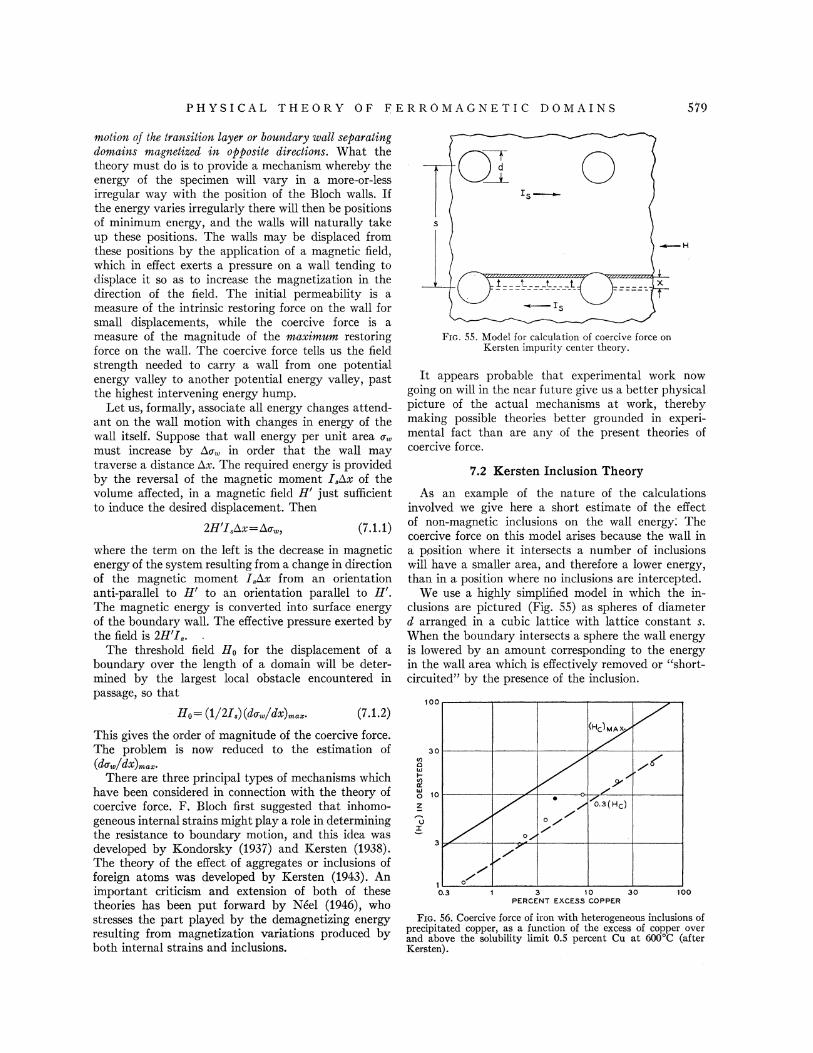
PHYSICAL THEORY OF F ERROMAGNETI C DOMAINS
motion of the transition layer or boundary wall separatingdomains magnetized in opposite directions. What thetheory must do is to provide a mechanism whereby theenergy of the specimen will vary in a more-or-lessirregular way with the position of the Bloch walls. Ifthe energy varies irregularly there will then be positionsof minimum energy, and the walls will naturally takeup these positions. The walls may be displaced fromthese positions by the application of a magnetic field,which in e8ect exerts a pressure on a wall tending todisplace it so as to increase the magnetization in thedirection of the field. The initial permeability is ameasure of the intrinsic restoring force on the wall forsmall displacements, while the coercive force is ameasure of the magnitude of the maximum restoringforce on the wall. The coercive force tells us the fieldstrength needed to carry a wall from one potentialenergy valley to another potential energy valley, pastthe highest intervening energy hump.
I.et us, formally, associate all energy changes attend-ant on the wall motion with changes in energy of thewall itself. Suppose that wall energy per unit area o.
must increase by 60;, in order that the wall maytraverse a distance d,x. The required energy is providedby the reversal of the magnetic moment I,hx of thevolume affected, in a magnetic field H' just sufhcientto induce the desired displacement. Then
2H'I, kx =Ao.„, (7.1.1)
where the term on the left is the decrease in magneticenergy of the system resulting from a change in directionof the magnetic moment I,dx from an orientationanti-parallel to H' to an orientation parallel to H'.The magnetic energy is converted into surface energyof the boundary wall. The effective pressure exerted bythe field is 2H'I, .
The threshold field Ho for the displacement of aboundary over the length of a domain will be deter-mined by the largest local obstacle encountered inpassage, so that
Po (1/2I.) (do /dx——)„., (7.1.2)
This gives the order of magnitude of the coercive force.The problem is now reduced to the estimation of(do /dx) ...
There are three principal types of mechanisms whichhave been considered in connection with the theory ofcoercive force. F. Bloch first suggested that inhomo-geneous internal strains might play a role in determiningthe resistance to boundary motion, and this idea wasdeveloped by Kondorsky (1937) and Kersten (1938).The theory of the effect of aggregates or inclusions offoreign atoms was developed by Kersten (1943). Animportant criticism and extension of both of thesetheories has been put forward by Neel (1946), whostresses the part played by the demagnetizing energyresulting from magnetization variations produced byboth internal strains and inclusions.
Frc. 55. Model for calculation of coercive force onKersten impurity center theory.
It appears probable that experimental work nowgoing on will in the near future give us a better physicalpicture of the actual mechanisms at work, therebymaking possible theories better grounded in experi-mental fact than are any of the present theories ofcoercive force.
100
300/)O4J
V)KLLI 10zVz
3
P'
~ 0.3(HC)
0 g
1
0.3 3 10 30PERCENT EXCESS COPPER
100
FIG. 56. Coercive force of iron with heterogeneous inclusions ofprecipitated copper, as a function of the excess of copper overand above the solubility limit 0.5 percent Cu at 600'C (afterKersten).
7.2 Kersten Inclusion Theory
As an example of the nature of the calculationsinvolved we give here a short estimate of the eGectof non-magnetic inclusions on the wall energy.
' Thecoercive force on this model arises because the wall ina position where it intersects a number of inclusionswill have a smaller area, and therefore a lower energy,than in a position where no inclusions are intercepted.
We use a highly simplified model in which the in-clusions are pictured (Fig. 55) as spheres of diameterd arranged in a cubic lattice with lattice constant s.When the boundary intersects a sphere the wall energyis lowered by an amount corresponding to the energyin the wall area which is effectively removed or "short-circuited" by the presence of the inclusion.
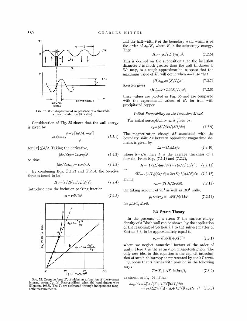
CHARLES KI TTEL
I
x
jj
-iREVER-
SIBLEE
I R REVERSIBLE
(a)
(b)Hp
Kersten gives(H,) „=(K/I, )n*.
(H,) ..=2.5(E/I, )ni;
(7.2.7)
(7.2.8)
these values are plotted in Fig. 56 and are comparedwith the experimental values of H, for iron withprecipitated copper.
and the half-width 8 of the boundary wall, which is ofthe order of o /E, where E is the anisotropy energy.Then
H, = (K'/I, ) (8/d) n*. (7.2.6)
This is derived on the supposition that the inclusiondiameter d is much greater than the wall thickness 6.We may, to a rough approximation, suppose that themaximum value of II, will occur when b=d, so that
FIG. 57. Wall displacement in presence of a sinusoidalstress distribution (Kersten).
Consideration of Fig. 55 shows that the wall energyis given by
s' —m L(d'/4) —x'jo(x) =op
$2
Initial Permeability orI, the Iecllsioe Model
The initial susceptibility xo is given by
gp = (dI/dx)/(dH/dx) . (7.2.9)
The magnetization change AI associated with theboundary shift Ax between oppositely magnetized do-mains is given by
for j x~ &d/2. Taking the derivative,
(do/dx) = 2ops x/ss
so that(do/dx) ..=oped/s'.
dZ =2I,Phx/s (7.2.10)
(7.2.2) where P=s/h; here ls is the average thickness of adomain. From Eqs. (7.1.1) and (7.2.2),
H = (1/2I, ) (do/dx) = 7r(o./I, ) (x/s'), (7.2.11)
By combining Eqs. (7.1.2) and (7.2.3), the coerciveforce is found to be dH =pr(o/I, ) (dx/s') = 27r(K/I, ) (h/s')dx (7.2.12)
H.= ( /2)( -/I. )(d/ ')~ ~
(7.2.4)Xp ——(pI ss/27rK6). (7.2.13)
Introduce now the inclusion packing fraction
n =xd'/6s' (7.2.5)
On taking account of 90' as well as 180' walls,
iup =47rxp ——1 6PI,'d/k8n'.
for po))1, d))8.
(7.2.14)
V)OLJ
K4JGzOx
7.3 Strain Theory
In the presence of a stress T the surface energydensity of a Bloch wall can be shown, by the applicationof the reasoning of Section 2.3 to the subject matter ofSection 3.3, to be approximately equal to
o. =2[A(E+XT)j' (7.3.1)
where we neglect numerical factors of the order ofunity. Here X is the saturation magnetostriction. Theonly new idea in this equation is the explicit introduc-tion of strain anisotropy as represented by the XT term.
Suppose that T varies with position in the followingway:
10 20T' IN KGJ'MIH2
30 T= Tp+hT sin2~x/l, (7.3.2)
FIG. 58. Coercive force P. of nickel as a function of the averageinternal stress T;: {a) Recrystallized wire, {b) hard drawn wire{Kersten, 1938).The T; are estimated through independent mag-netic measurements.
as shown in Fig. 57. Then
do„/dx=7 [a/(K+ZT)] '(dT/dx)-= (2mAAT/l)LA/(K+AT)]' cos2mx/l (7.3.3)

PHYSICAL THEORY OF FERROMAGNETIC DOMAINS 58i
which assumes the maximum value
(do/dx) .,= (2m.XET/l) [A/(E+) T)]'. (7.3.4)
This gives approximately
(7.3.5)
where 6 is the thickness of the Bloch wall and / is thescale of the stress variation.
From Eqs. (7.1.2) and (7.3.5),
(7.3.6)
S S
N N N
s
(a)
/
/
~slt
////
/
/
NN &S
Experimental results showing the dependence of II, onthe magnitude of the internal stress AT are given inFig. 58.
This sketchy calculation should be adequate to getacross the idea that the coercive force depends on themagnitude of the stress variation as a consequence ofthe dependence of the wall energy on stress. We mightexpect this mechanism to be of importance in materialwith high magnetostriction such as nickel. For furtherdetails it is suggested that the reader consult theoriginal papers of Kondorsky (1937) and Kersten(1938).
tv. = (1/2) (4v./3) (4v a'/3) I.', (7.4.1)
7.4 Neel Magnetization Fluctuation Theory
Neel (1944b, 1946) has suggested that the inclusionand strain theory calculations are seriously in error inseveral respects. First, the implicit assumption of aregular distribution of irregularities, as for example theassumption of inclusions on a cubic lattice, greatlyovervalues the coercive force for actual materials wherethe perturbations might be supposed to be more-or-lessrandom. Second, the assumption of rigid domain wallsalso acts to give too high values of the coercive force.When the appropriate corrections for these factors aremade the maximum coercive force yielded by thetheory, according to Xeel, is of the order of one oersted,which is much too small to account for the coercivityof many magnetic materials.
Neel points out that the magnetic energy associatedwith inclusions or stress variations may be considerablygreater than the changes in wall energy associated withthe same structure. Consider for example the twopositions of the wall shown in Fig. 59. In the position(a) the magnetic energy of the inclusion' in the formof a sphere of radius g is, from Eq. (2.4.3),
Fro. 59. Figure illustrating the dependence of magnetic energy ofan inclusion on the position of a boundary wall.
By a sophisticated development of this basic idea inthe 1946 paper, Xeel obtains
Iron: H, =2.1v+360v' oersteds, (7.4.3)
Nickel: H, =330v+ 97v' oersteds. (7.4.4)
Here L' is the fraction of the volume occupied byinclusions and v is the fraction of the volume subjectedto irregular internal stresses of magnitude 30 Kg/mm'.
The work of Williams and Shockley on an ironcrystal with simple domain structure suggests that theinteraction of the principal domain boundaries with thedagger blade domains (Section 5.2.3) around crystalimperfections plays an important part in determiningthe coercive force of this particular educated crystal. Itappears likely that further work of this character willgive a more satisfying physical basis to our under-standing of the mechanism of coercive force.
ACKNOWLEDGMENTS
I wish to thank those who have offered suggestionson the manuscript: in particular R. M. Bozorth, K. K.Darrow, J. K. Gait, A. N. Holden, L. Tisza, and J. H.Van Vleck. The photographs of domain patterns havebeen generously made available by H. J. Williams. J. G.Walker has been of constant help in organizing the6gures, and in this and other ways has shown to howhigh a value the multiplication factor of a technicalassistant can rise; Mrs. E. M. Sparks has been of similarservice in organizing the manuscript.
APPENDIX A
Mathematical Expressions for the Anisotropyof Cubic Crystals
The expression (Eq. (2.2.4))whereas the magnetic energy in position (b) is
xg= 0.46m, (7.4.2)
fK =+1(~12~22+~12~32+22~32) (A.1)
in the direction cosines n1, n2, n3 of the magnetization referred tothe cubic axes becomes
according to a potential theory calculation given inNeel's 1944 paper. The difference in energy betweenm and m~ is a measure of the field which must beapplied in order to make the wall move from position(a) to position (b).
f~= E1 sin20 cos20= 4'E1 sin20
in the (001) plane, where n3=0.For small a2, n3'.
f~~E.102
where e is the polar angle between n and the L100$ axis.
(A.2)
(A.s)

CHA RI.ES K I TTE L
If we write Eq. (A.1) in terms of a polar angle g and an azi-muthal angle q, then (Neel, 1944)
f~ =Xi(sin'g ——,' sin4g —
8 sin g cos4q) (A.4)
when the polar axis is a cube side; and
/ E(-; ='3+'t '3—3 i '3 3g (A 3)3
when the polar axis is a body diagonal; finally,
fx —,'E= 3$(1—4 sin'8+4 sin48)+ (6 sin'8 —4 sin48)sinsq—3 sin48 sin422$ (A.6)
when the polar axis is a face diagonal. The azimuthal angle q isreferred to a cube edge.
APPENDIX B
for a face-centered cubic lattice, where
3 1 5l4S=-z,'2 (Pym'+n')"' (P+m'+n')'f' (B 7)
For b.c.c., S=0.4; while for f.c.c., S=0.6. We have then for iron,which is body-centered,
Calculated: B3=—0.7X10' ergs/cc; B2=0.5X10' ergs/ccObserved: B3=—2.9X10' ergs/cc; B2 6 4X——10.' ergs/cc
and for nickel, which is face-centered,
Calculated: B3= —0.04X 10"ergs/cc; B2=0.03X 10' ergs/ccObserved: B3= 6.2 X10"ergs/cc; B2=9.0 X10' ergs/cc.
The comparison of calculated with observed values demonstratesthe inadequacy of dipole-dipole interactions.
Magnetic Interaction Energy of Dipoles ona Cubic Lattice
P+n '(m' —P)+o.P(n' —P)—3 Z'(P+m'+n')@' (B.3)
where we have omitted across terms in lm, ln, etc. , since theseobviously sum to zero. Now
l2 m2 n2= Z' = Z' (B.4)$~„(P+m+n') ~ $~ {P+m'+n )5~'
) (P+m'+n') "by symmetry, so that the terms in n2, n3 are identically zero,which leaves only a term independent of the direction of magnet-ization. There is therefore no anisotropy for a simple cubiclattice; the same result applies to body-centered and face-centered cubic lattices. It may further be seen that f=0.
If, however, we allow the lattice to deform spontaneously themagnetic dipole interaction will give rise to magnetostriction andthus, by an argument which we have given earlier, to an apparentand small contribution to the anisotropy. Becker (1930) hasshown that the magnetostriction resulting from dipole-dipoleinteractions is only about one-fifth of the observed magneto-striction in iron, while in nickel the magnetostriction calculatedon this basis does not agree with the observed value even inalgebraic sign. We, therefore, see that the magnetic dipole inter-action from saturation magnetization on a regular lattice explainsneither the observed anisotropy nor the observed magnetostric-tion.
On Becker's calculation the magnetoelastic coupling constants(Eq. (2.3.5)) are equal to
Bi=—6SI,'; B2=4SI,' (3.5)
for a body-centered cubic lattice, and
Bi=—3SI ' B2=2SI ' (8.6)
We propose to prove now the well-known fact that the magneticmoment interaction between dipoles on an infinite unstrainedcubic lattice gives no anisotropy energy. The magnetic interactionenergy between any two dipoles of the array is
p"p 3(p' r';)(p; r';)r rs
so that the total dipole interaction energy density of a saturatedsimple cubic lattice is
1 3(l~,+m, +~,)2
(12+2322+ N2) 3/2 (12+3/32+ N2) 3/2
where N is the number of dipoles per unit volume, n is the direc-tion of the magnetization, and r=(z, y, s)=(la, ma, Na) is thevector from the dipole at the origin to the dipole at the latticepoint (l, m, n). The first term in the sum does not contain anyreference to the direction of magnetization and therefore cannotgive anisotropy. The second term may be rewritten, using
nP=1 —n22 —nP, as
APPENDIX C
List of Symbols
B= Magnetic induction =H+4m I.H= Magnetic field intensity.
H y= Effective molecular field.I= Magnetization =Magnetic moment/volume.I,=Saturation magnetization.Io= Saturation magnetization at O'K.E=Anisotropy energy density constant.J=Exchange integral.
T,= Curie temperature.k=Boltzmann constant=1. 38X10 " ergs/degree abso-
lute.rr= (nr, n2, n2) = (n2, n„,32,)=direction cosines of magnet-
ization vector, referred to the crystal axes.xiii, &ioo= Saturation magnetostriction constants.
c», c», c44= Elastic moduli of cubic crystal.e;;=Components of strain.f= energy per unit volume= energy density.f„=exchange energy density.
f3333 anisotropy energy density.f,=magnetoelastic energy density.f „=magnetic energy density.f.3= elastic energy density.
Bi, B2=magnetoelastic coupling constants.N= number of atoms per unit volume.u = lattice constant.
0„=Bloch wall energy per unit area.q =angle between directions of adjacent spins.
n,fy= effective number of Bohr magnetons per atom.A = exchange energy constant.
/3/3 —Bohr magneton= 0.927 X 10 "ergs/oersted.T= stress; absolute temperature.g= linear pole density.S=spin quantum number.x= susceptibility per unit volume I/H.p =permeability = 1+4rx.
p*=effective permeability of a single domain for fields atright angles to the direction of domain magnetization;see Section 2.4.
BIBLIOGRAPHY
(Different papers by the same author in the same yearare distinguished by letters after the year, as in 1944b.)
I. Antik and T. Kubyschkina, Uber die Hysteresisverluste inQussigen Ferromagnetika (Amalgamen), Wiss. Ber. MoskauerStaatsuniversitat 2, 143-149 (1934).I. F. Bates and F. E. Neale, "A quantitative examination ofrecent ideas on domain structures, "Physica 15, 220—224 (1949).
S. J. Barnett, "New researches on magnetization by rotation andthe gyromagnetic ratios of ferromagnetic substances, " Proc.Am. Acad. Sci. 75, 109-129 (1944).
PHYSI CAL THEORY OF FERROMAGNF TI C DOMAINS
R. Seeker, Zur Theoric der Magnetisierungskurve, Zeits. f. Physik62, 253-269 (1930).
R. Becker, Elastische Spannungen und magnetische Eigen-schaften, Physik. Zeits. 33, 905-913 (1932}.
R. Becker and W. Doring, Ferromagnetismus (Verlag. JuliusSpringer, Berlin; reprinted J. W. Edwards, Ann Arbor, 1939).
F. Bitter, On inhomogeneities in the magnetization of ferro-magnetic materials, Phys. Rev. 38, 1903-1905 (1931).
F. Bloch, Zur Theorize des Ferromagnetismus, Zeits. f. Physik 61,206-219 (1930).
F. Bloch, Zur Theoric des Austauschproblems und der Remanen-zerscheinung der Ferromagnetika, Zeits. f. 'Physik 74, 295—335(1932).
R. M. Bozorth, Directional ferromagnetic properties of metals,J. App. Phys. 8, 575—588 (1937).
R. M. Bozorth, Magneto-resistance and domain theory of iron-nickel alloys, Phys. Rev. 70, 923 (1946}.
R. M. Bozorth, On magnetic remanence, Zeits. f. Physik 124,519-527 (1948).
Bozorth, Mason, McSkimin, and Walker, "Elastic constants andinternal loss of single nickel crystals, " Phys. Rev. 75, 1954(1949).
H. Brooks, "Ferromagnetic anisotropy and the itinerant electronmodel, " Phys. Rev. 58, 909-918 (1940).
Surgy, Hughes, and Wallace, Double transmission and depolar-ization of neutrons, Phys. Rev. 74, 1207 (1948).
A. Drigo and M. Pizzo, Particolari aspetti della magnetizzazionedi sottili pellicole ferromagnetiche, Il Nuovo Cimento 5, 1—11(1948).
W. C. Elmore, The magnetization of ferromagnetic colloids,Phys. Rev. 54, 1092-1095 (1938).
W. C. Elmore, Theory of the optical and magnetic properties offerromagnetic suspensions, Phys. Rev. 60, 593—596 (1941).
M. Fallot, Ferromagndtisme des alliages de fer, Annales' dePhysique 6, 305—387 (1936).
A. D. Fokker, Remark on the fundamental relations of thermo-magnetics, Physica 6, 791-796 {1939).
J. Frenkel and J. Dorfman, Spontaneous and induced magnetiza-tion in ferromagnetic bodies, Nature 126, 274—275 {1930).
L. H. Germer, Stray magnetic fields from cobalt, Phys. Rev. 62,295 (1942).
E. A. Guggenheim, On magnetic and electrostatic energy, Proc.Roy. Soc. A155, 49-70 {1936).
C. Guillaud, Ferromagnetisme des alliages binaires de manganese,Thesis, Strasbourg, 1943.
C. Herring and C. Kittel, Energy of a Bloch wall on the bandpicture, Phys. Rev. (to be submitted).
H. Honda and S. Kaya, Magnetization of single crystals of iron,Sci. Rep. Tohoku Univ. 1S, 721—753 (1926).
S. Kaya, On the magnetization of single crystals of nickel, Sci.Rep. Tohoku Univ. 17, 639—663 (1928a).
S. Kaya, On the magnetization of single crystals of cobalt, Sci.Rep. Tohoku Univ. 17, 1157—1177 {1928b).
M. Kersten, I'robleme der techmschen Magnetisierungskurve, ZurDeutung der Koerzitivkraft, edited by R. Becker (Verlag.Julius Springer, Berlin; reprinted J. W. Edwards, Ann Arbor,1938), pp. 42-72.
M. Kersten, Grundlagen earner Theoric der ferromagnetischenHystorese siad dor Koorsv'tvvfsruft (S. Hirzel, Leipzig; reprintedJ. W. Edwards, Ann Arbor, 1943).
L. Kholodenko, On the domain structure of ferromagnetic bodiesin the presence of a magnetic field (in Russian), J. Exp. Theo.Phys. USSR 17, 698—707 (1947).
R. Kimura and K. Ohno, On the elastic constants of singlecrystals of iron, Sci. Rep. Tohoku Univ. 23, 359-364 (1934).
C. Kittel, Theory of the structure of ferromagnetic domains infilms and small particles, Phys. Rev. 70, 965—97l. (1946).
C. Kittel, Domain theory and the dependence of the coerciveforce of Qne ferromagnetic powders on particle size, Phys. Rev.73, 810 (1948).
C. Kittel, Gyromagnetic ratios and splitting factors of ferro-magnetic substances, Phys. Rev. 76, 743 (1949a).
C. Kittel, Theory of the formation of powder patterns on ferro-magnetic crystals, Phys. Rev. 76, 1527 (1949b).
E. Kondorsky, On the nature of the coercive force and irreversiblechanges in magnetization, Physik. Zeit. Sow. 11,597—620 (1937).
A. Kussmann and B. Scharnow, Zeits. f. Physik 54, 1—15 (1929}.Uber die Koerzitivkraft. I. Teil. Koerzitivkraft und mechan-ische Harte.
L. Landau and E. Lifshitz, On the theory of the dispersion ofmagnetic permeability in ferromagnetic bodies, Physik. Zeits.Sowjetunion 8, 153-169 {1935).
E. Lifshitz, On the magnetic structure of iron, J. Phys. U.S.S.R.8, 337-346 (1944).
L. Marton, Ferromagnetic domain observation, Phys. Rev. 73,1475 {1948).
B.Matthias and A. von Hippel, Domain structure and dielectricresponse of barium titanate single crystals, Phys. Rev. 73,1378-1384 (1948).
C. Moiler, Zur Theoric der Austauschproblems und des Ferro-magnetismus bei tiefen Temperaturen, Zeits. f. Physik. 82,559-567 (1933).
L. Noel, Quelques propri6tes des parois de domaines 616mentairesferromagnbtiques, Cahiers de Physique 25, 1—20 (1944a}.
L. Neel, Effet des cavites et des inclusions sur le champ coercitif,Cahiers de Physique 25, 21-44 (1944b).
L. Neel, Les lois de 1 aimantation et de la subdivision en domaineselbmentaires d'un monocristal de fer, J. de phys. et rad. 5,241-251, 265-276 (1944c).
L. Neel, Bases d'une nouvelle theoric generale du champ coercitif,Annales Univ. Grenoble 22, 299—343 (1946).
L. Neel, Proprietes d'un ferromagnetique cubique en grains fins,Comptes rendus (Paris) 224, 1488—1490 (1947a).
L. Neel, Le champ coercitIf d'une poudre ferromagnetique cubiquea grains anisotropes, Comptes Rendus (Paris) 224, 1550-1551{1947b).
L. Neel, Theoric de 1'anisotropie a aimants traites a chaud dansun champ magnetique, Comptes Rendus (Paris) 225, 109-111(1947c}.
J. A. Osborn, Demagnetizing factors of the general ellipsoid,Phys. Rev. 67, 351—357 (1945).
W. Shockley, Energy calculations fox domains, Phys. Rev. 73,1246 (1948).
K. J. Sixtus and L. Tonks, Propagation of large Barkhausendiscontinuities, IV, Regions of reversed magnetization, Phys.Rev. 43, 931—940 (1933).
A. Sommerfeld and H. Bethe, Elektronentheorie der Metalle,Handbuch der Physik 24.2, 333—622 (1933).
E. C. Storier and E. P. %ohlfarth, Interpretation of high co-ercivity in ferromagnetic materials, Nature 160, 650 (1947).
E. C. Stoner and E. P. Wohlfarth, A mechanism of magnetichysteresis in heterogeneous alloys, Phil. Trans. A240, 599—644(1948).
J. H. Van Vleck, A survey of the theory of ferromagnetism, Rev.Mod. Phys. 17, 27-47 {1945).
J. H. Van Vleck, Quelques aspects de la theoric du magnetisme,Annales de 1'Institut Henri Poincare 10, 57—190 (1947).
S. V. Vonsovsky and J. S. Shur, Ferromagnetism (in Russian),(OGEZ, Moscow, 1948).
L. Weil, Variation du champ coercitif en fonction de la densityde poudres ferromagnetiques agglomerees, Comptes Rendus(Paris) 225, 229-230 (1947).
L. Weil and S. Marfoure, Variation thermique du champ coercitifdu nickel agglomere, J. de phys. et rad. 8, 358-361 (1947).
P. %eiss, L'hypothese du champ molbculaire et la propribt5ferromagnetique, J. de Phys. 6, 661—690 (1907).
P. R. %eiss, The application of the Bethe-Peierls method toferromagnetism, Phys. Rev. 74, 1493-1504 (1948).
H. J. Williams, Direction of domain magnetization in powderpatterns, Phys. Rev. 71, 646 (1947).
Williams, Bozorth, and Shockley, Magnetic domain patterns onsingle crystals of silicon iron, Phys. Rev. 75, 155-178 (1949).
H. J. Williams and W. Shockley, A simple domain structure inan iron crystal show'ing a direct correlation with the magnetiza-tion, Phys. Rev. 75, 178-183 (1949).
W. A. Yager, Phys. Rev. (to be submitted).