Embed Size (px)
Citation preview

Unit 1
Electronics
Name: Form:
2
Electronics Electronics is the study of components and techniques used to be able to build circuits controlled by electricity. An electronic system uses discrete components. Any electronic system is made up of three parts. The relationship between these parts is governed by the different variables, Voltage, Current and Resistance. Batteries
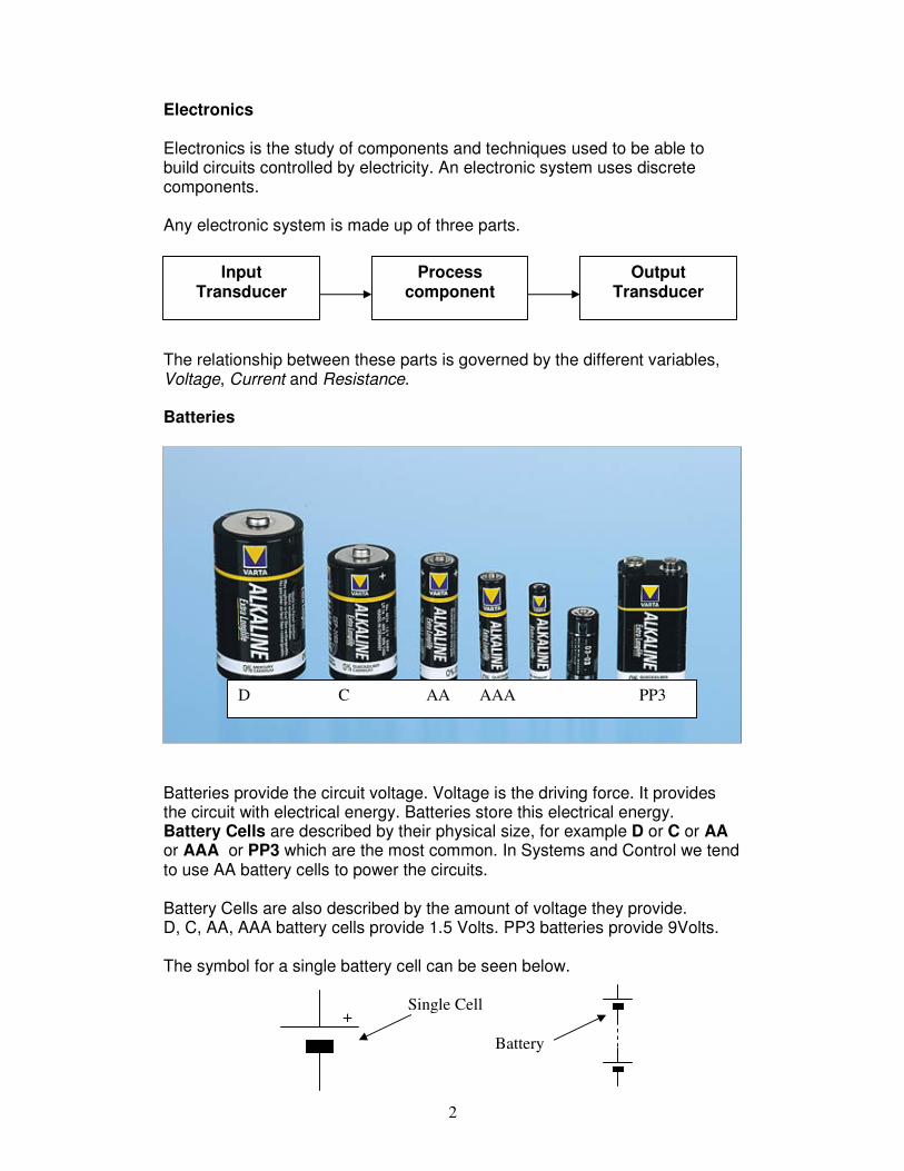
Batteries provide the circuit voltage. Voltage is the driving force. It provides the circuit with electrical energy. Batteries store this electrical energy. Battery Cells are described by their physical size, for example D or C or AA or AAA or PP3 which are the most common. In Systems and Control we tend to use AA battery cells to power the circuits. Battery Cells are also described by the amount of voltage they provide. D, C, AA, AAA battery cells provide 1.5 Volts. PP3 batteries provide 9Volts. The symbol for a single battery cell can be seen below.
Input Transducer
Output Transducer
Process component
D C AA AAA PP3
+ Single Cell
Battery
3
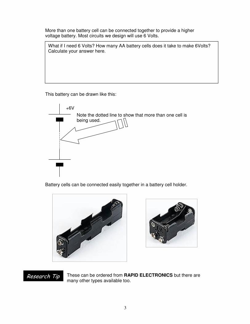
More than one battery cell can be connected together to provide a higher voltage battery. Most circuits we design will use 6 Volts. This battery can be drawn like this:
Battery cells can be connected easily together in a battery cell holder.
These can be ordered from RAPID ELECTRONICS but there are many other types available too.
What if I need 6 Volts? How many AA battery cells does it take to make 6Volts? Calculate your answer here.
+6V
Note the dotted line to show that more than one cell is being used.
Research Tip

4
Batteries How do I know if I am choosing the right battery?

5
Electronic Units V, I and R
What is Voltage? Voltage is the electro motive force of any circuit and is measured in Volts. A battery cell has two main specifications:
Physical size for example AA Voltage for example 1.5Volts
They can be connected together in series. Rapid Electronics provide battery holders for your projects. What is Current? If voltage is a force then current is a flow. Current is the amount of electrons flowing around the circuit being provided by the battery cells. What is current measured in? Current is measured in Amperes shortened to AMPS.
+6V
Conventional current flows out of the battery positive (RED) terminal through a circuit and back to the negative (BLACK) terminal. A circuit will resist the flow of this current, and therefore we can control the amount of current flowing around a circuit.
+6V
Colour in the POSITIVE and NEGATIVE wires the correct colours
POSITIVE, +Ve connection will be RED
NEGATIVE, -Ve connection will be BLACK

6
What if I need to draw a Circuit Diagram? How can I remember to draw a circuit diagram? Steps to drawing a circuit diagram
1. Start with a battery and draw this on the left hand side of your page. 2. Next add in +Ve Volts supply rail at the top of the space 3. Leave a reasonable gap 4. Then add the –Ve supply rail at the bottom of the space 5. Now add your input component 6. Next is the process component 7. Finally add in your output component. 8. Now draw in the wires to connect your circuit
MNEMONIC = Bat Rail + Gap – IN Proc Out Wires [BR+G-IPOW] Can I draw a series circuit that uses two switches and lights up a LED, remember an LED needs a resistor? Specifications:
Use a 6V battery Use two push button switches
Use a 330Ω resistor
HINT
SERIES:
Eastenders is a series

7
Can I …follow the steps again and draw a parallel circuit to light up an LED when one of two switches is pressed. Specifications:
Use a 6V battery Use two push button switches
Use a 330Ω resistor
HINT:
Parallel:
A ladder is parallel

8
FACTOID What if I get electrocuted? Did you know it only take 0.03A to flow across your heart to cause it to stop beating? That’s 3 100ths of an AMP! A Vacuum cleaner uses 8 Amps to work! Why do batteries go flat? When designing a circuit check that the batteries used will provide enough current for your circuit. What is Resistance? FACTOID: A resistor will resist or limit the flow of current around a circuit. They can be used to SET a particular voltage needed in a circuit.
Resistors are measured in OHMS, which has the symbol ΩΩΩΩ.
Resistors DO NOT STOP the flow of current. Each resistor has a particular colour code that tells us its resistance. How can I work out its resistance? Here is the key.
Colour Colour Band 1 Colour Band 2 Colour Band 3 Tolerance Black 0 0 nothing Brown 1 1 0 Gold = +/- 5% Red 2 2 00 Orange 3 3 000 Silver = +/- 10 % Yellow 4 4 0000 Great 5 5 00000
Blue 6 6 000000 Violet 7 7 0000000 Grey 8 8 00000000 White 9 9 000000000
ALWAYS read the resistor left to right with the tolerance band on the RIGHT
Brown Black Red Gold Band 1 Band 2 Band 3 Tolerance 1 0 00 +/- 5%
Therefore this resistor is 1000 Ω

9
Can you decode the resistors below USE A PENCIL 1 Brown Black Orange Gold 2 Brown Red Red Gold 3 Yellow Violet Black Gold 4 Orange Orange Brown Gold 5 Red Red Red Gold Now work back wards. Assume the tolerance band +/-5%
6) 27KΩ . Band 1 = 2 Band 2 = 7 Band 3 = K and K is 000 (1Kg is 1000grammes
likewise 1KΩ = 1000 Ohms. 2 = RED, 7=Violet, 000 = Orange Answer = RED VIOLET ORANGE GOLD
7) 100KΩ
8) 15Ω
9) 270Ω
10) 18KΩ

10
Draw and colour the following resistors all with a tolerance of +/-5%:
1. 1KΩ
2. 22KΩ
3. 330Ω
4. 10KΩ
5. 4K7Ω

11
Ohm’s Law Ohm’s law states the relationship between current (I measured in Amps),
voltage (V measured in Volts) and resistance (R measured in Ohms Ω) in any electrical circuit. It is given as: V = I x R R = V I I = V R So if we know two of these we can work out the other one. Question: Work out the value of the resistor R in the circuit below. What do we know? V = I = R = Which formula shall we use? R = V I Substitute in the values. R = 6 2 R = 3 Amps
+6V
2A
R Ω

12
Calculate the missing value
+V
1A
100 Ω
What is V? Put you workings here.
+6V
I
60 Ω
What is I? Put you workings here.
+4V
0.02
R
What is R? Put you workings here.

13
Designing using Ohm’s Law I need a resistor to limit the current flowing in an LED because the maximum an LED can take is 0.02A, any more and it will break. When an LED is switched on it will drop 2Volts across itself. This is the voltage needed to push the electrons through the LED. So a circuit with an LED will look like this.
V measured across R = 6 – 2 = 4Volts I flowing through R = 0.02A Therefore R = V I R = 4 0.02
R = 200 Ω
+6V
0.02A
2V
R Ω
Research Tip
If you are using LEDS In your coursework put this calculation in to prove you know how to design the value of correct resistors for your circuit.

14
Design a series circuit to switch on 2 LEDS using a 9Volt battery and a DPDT toggle switch.
Step 1 Draw the circuit diagram.
Step 2 Calculate the resistor needed for the circuit.
Build your circuit on a breadboard.

15
Self Assessment Quiz 1 - 10 minutes maximum 1 Match the following symbols with the correct names:
2. Calculate the Voltage in a circuit when I = 2 Amps and R = 220Ω 3. The current flowing through an LED has a limit, what is that limit? 4. What is resistance measured in? 5. Using the resistor colour code what colour bands would be found on the following, assume a tolerance of GOLD?
1K Ω
220 Ω
390 Ω
22K Ω
10K Ω
+
Battery cell Resistor LED

16
How do you connect up a sensor?
A sensor is a clever bit of technology; which uses a smart material. A sensor will detect a change in something and respond to that change in some way. Think of an LDR. It responds to changes in light. Think of a Thermistor. It responds to changes in temperature. But a component on its own is no good. It needs to be connected into a circuit. That’s where a potential divider circuit is used to make use of these changes.

17
What If… What if I connected an LED in series with an LDR would it light up when it got dark? Why …. Write a question you have about the circuit here

18
Potential Divider Circuits Two resistors connected in series will work as a potential (voltage) divider.
Try it using a bread board, 2 1K resistors, and a multimeter.
+6V
1KΩ
1KΩ 3V
6V
Multimeter set to 20V DC scale
Breadboard
Multimeter

19
Bread Boards A breadboard allows you to model your circuit without the need for solder. It consists of holes with copper strips underneath to connect the components. The holes are therefore connected together as shown by the lines on the picture. So your potential divider system would look like this.
RED
BLACK
1K
1K
Components connected
inside the breadboard

20
10KΩ
22KΩ
Using a Multimeter to test for DC Voltage
Set up this circuit on the Breadboard and measure V1
RED
BLACK
DC Range
+6V
V1
6V
Multimeter set to 20V DC scale
My V1 measurement is : ____________________ Volts

21
Crocodile clips Circuit for potential divider

22
Vs
Rtop
Rbot
Designing a Potential Divider Circuit
If Vs = 6 Volts and Rtop = 10K and Rbot = 22K Then we can use this formula to calculate the Voltage across Rb(bot) VRb = Vs x Rbot Rtop + Rbot VRb = 6 x 22
10 + 22 VRb = 6 x 22 32 VRb = 6 x 0.3125
VRb = 1.875 Volts
Your Turn Calculate VRb in the circuit below
6V
100K
1000K
Show your workings here

23
Self Assessment Quiz 2 - 10 minutes maximum What is a breadboard when used in electronics? Which range would you use on a Multimeter to measure a battery? Use a ruler to draw a potential divider circuit with Vs = 9V, Rt = 22K and Rb = 68K. Calculate the Voltage across Rb in your potential divider circuit.

24
Input Transducers The start of any system is the input. Find the symbols for each of the transducers listed below and add them to the mind map.
Input Transducer
Output Transducer
Process component
25
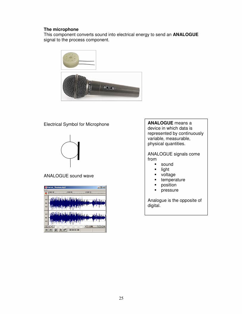
The microphone This component converts sound into electrical energy to send an ANALOGUE signal to the process component.
Electrical Symbol for Microphone ANALOGUE sound wave
ANALOGUE means a device in which data is represented by continuously variable, measurable, physical quantities. ANALOGUE signals come from
sound light voltage temperature position pressure
Analogue is the opposite of digital.

26
The Variable Resistor This component converts kinetic energy into electrical energy and sends an ANALOGUE signal of position to the process component.
Electrical symbol for a variable resistor.
Switches These components convert kinetic energy into electrical energy and send DIGITAL signals to the process component. In systems design micro switches are used to ‘sense’ the presence of doors, lids or any part of a machine to tell a process to activate/deactivate.
Other types of switches are used to control the power to a circuit – commonly referred to as ON/OFF switches and tend to be toggle or slide switches.
Push button
DPDT

27
Symbols for switches Switch Symbol Description Single Pole Single Throw SPST
A basic ON/OFF switch
Single Pole Single Throw SPST
Push button
Single Pole Double Throw SPDT
Micro switch
Double Pole Double Throw DPDT
Two reversing switches in one
Digital Signals A digital signal is either ON or OFF, there is no in between as with sound levels or light levels. Using BINARY a digital ON is known as a 1 and a digital OFF is known as a 0. Moisture Sensor A moisture sensor makes use of the conductivity of water. When water falls between two pieces of wire current will flow and the sensor sends a 1 signal to a process device.
SAQ Is a moisture sensor a Digital or Analogue component?
NC
NO
Wires to process device
Moisture sensor copper tracks
Is it wet? Yes or No 1 or 0 is sent to the process component
Symbol:

28
Thermistor A thermistor is a resistor that changes its resistance depending on the temperature. A NTC (Negative Temperature Coefficient) thermistor will decrease in resistance as temperature rises. A PTC (Positive Temperature Coefficient) thermistor will increase its resistance with the increase in temperature. A typical response of the NTC thermistor to temperature can be seen here.
-t o +t o
PTC NTC
This particular NTC thermistor is 10K @ 25oC However as temperature increases @ 43oC it is 5K

29
LDR Light Dependant Resistor. As light levels fall so the resistance increases.
A graph showing the relationship of light against resistance is shown below. SAQ Is an LDR analogue or digital? SAQ Is a thermistor analogue or digital?
Resistance
Light Level (Lux)
30
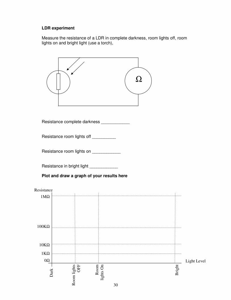
LDR experiment Measure the resistance of a LDR in complete darkness, room lights off, room lights on and bright light (use a torch), Resistance complete darkness ____________ Resistance room lights off __________ Resistance room lights on ____________ Resistance in bright light ____________ Plot and draw a graph of your results here
Ω
Light Level
Resistance
Bri
gh
t
Ro
om
lig
hts
On
Ro
om
lig
hts
OF
F
Dark
1MΩ
100KΩ
10KΩ
1KΩ
0Ω

31
Connecting Input Components Input components need to be INTERFACED (joined or connected to) with process components, and to do this we need to connect them into a potential divider circuit. We can then design the Input part to any circuit. A Darkness Sensor Circuit For example:
Connect up this circuit on a breadboard and measure VRb (Voltage across Resistor bottom) in complete darkness and in daylight. Bright Light (Torch) __________Volts Daylight reading _____________ Volts Complete Darkness ___________Volts This arrangement of the potential divider circuit will detect darkness.
If in darkness the LDR = 1,000,000 Ω Calculate VRb VRb = Vs x Rb Rt+Rb VRb = 6 x 1,000,000 1,010,000 VRb = 5.94V
+6 10K
VRb
32
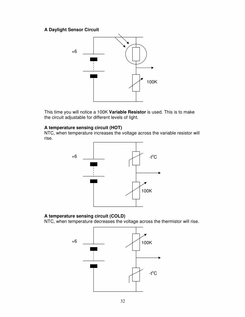
A Daylight Sensor Circuit
This time you will notice a 100K Variable Resistor is used. This is to make the circuit adjustable for different levels of light. A temperature sensing circuit (HOT) NTC, when temperature increases the voltage across the variable resistor will rise. A temperature sensing circuit (COLD) NTC, when temperature decreases the voltage across the thermistor will rise.
+6
100K
+6
100K
-toC
+6 100K
-toC

33
Connecting Switches Switch Sensing Circuit – Output when pressed This could be for micro switch, pressure mat, tilt switch or reed switch. Switch Sensing Circuit – Output when NOT pressed SAQ – Input Transducers 1 Which input component would you use to detect temperature? 1 2 What component is this symbol for? 2 3 When it gets dark the resistance of and LDR rises, TRUE or FALSE? 1
+6
10K
+6 10K
NC
NO

34
4 Circle the odd one out 1 Battery LDR Micro Switch Push Button Now give a reason why: 2 5 Circle the odd one out 1
LDR Thermistor Switch Moisture Sensor
Now give a reason why: 2 6 DPDT stands for Double Press Double Touch True or False 1 7 DPDT refers to Thermistors. True or False 1 8 Draw the symbol for a SPST switch. 2 9 Make a list of FOUR digital input components 4 10 What does Analogue mean? 2
[20]