Embed Size (px)
Citation preview
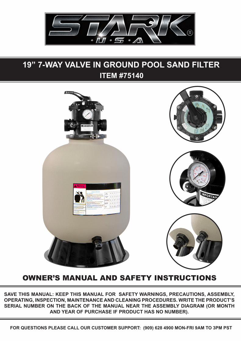
19” 7-WAY VALVE IN GROUND POOL SAND FILTER
SAVE THIS MANUAL: KEEP THIS MANUAL FOR SAFETY WARNINGS, PRECAUTIONS, ASSEMBLY, OPERATING, INSPECTION, MAINTENANCE AND CLEANING PROCEDURES. WRITE THE PRODUCT’S SERIAL NUMBER ON THE BACK OF THE MANUAL NEAR THE ASSEMBLY DIAGRAM (OR MONTH
AND YEAR OF PURCHASE IF PRODUCT HAS NO NUMBER).
OWNER’S MANUAL AND SAFETY INSTRUCTIONS
ITEM #75140
FOR QUESTIONS PLEASE CALL OUR CUSTOMER SUPPORT: (909) 628 4900 MON-FRI 9AM TO 3PM PST

IMPORTANT SAFETY INFORMATION
GENERAL SAFETY WARNINGSSERIOUS BODILY INJURY OR DEATH CAN RESULT IF THIS SAND FILTER IS NOT INSTALLED AND USED CORRECTLY. INSTALLERS, POOL OPERATORS AND POOL OWNERS MUST READ THESE WARNINGS AND ALL INSTRUCTIONS BEFORE USING THIS SAND FILTER.
SAFETY Most states and local codes regulate the construction, installation, and operation of public pools and spas, and the construction of residential pools and spas. It is important to comply with these codes, many of which directly regulate the installation and use of this product. Consult your local building and health codes for more information.
IMPORTANT: Attention Installer: This Installation and User’s Guide contains important information about the installation, operation and safe use of this sand filter. This Guide should be given to the owner and/or operator of this equipment.
1
The sand filter is designed to work with water temperature > 0° C and < than 45 0° C. The filter should never be operated outside of these temperatures or damage may occur. The installation should be carried out in accordance to the safety instructions of swimming pools and the specific instructions for each facility.
Failure to remove pressure test plugs and/or plugs used in winterization of the pool/spa from the suction outlets can result in an increase potential for suction entrapment.
To reduce the risk of injury, do not permit children to use or operate this sand filter.DO NOT store chemicals around your pool. Chemical spills and fumes can weaken swimming pools and/or spas.
Any modifications of this filter requires prior consent from the supplier’s original replacement and accessories authorized by the manufacturer to ensure a high level of safety. The supplier assumes no liability for any damage or injuries caused by unauthorized replacement parts and/or accessories. In the even of defective operation or fault, contact the supplier or the nearest authorized service agent.
Components such as the filtration system, pumps and heater must be positioned so as to prevent their being used as means of access to the pool by young children.
NEVER operate or test the circulation system at more than 40 PSI.
All electrical wiring MUST be performed by a qualified professional, and MUST conform to local codes and regulations.
Hazardous Pressure. Pool and spa water circulation systems operate under hazardous pressure during start up, normal operation, and after shut off. Stand clear of circulation system equipment during pump start up. Failure to follow safety and operation instructions could result in violent separation of the pump housing and cover, and/or filter housing and clamp due to pressure in the system, which could cause property damage, severe personal injury, or death. Before servicing pool and spa water circulation system, all system and pump controls must be in off position and filter manual air relief valve must be in open position. Before starting system pump, all system valves must be set in a position to allow system water to return back to the pool. DO NOT change filter control valve position while system pump is running. Before starting system pump, fully open filter manual air relief valve. DO NOT close filter manual air relief valve until a steady stream of water (not air or air and water) is discharged.

IMPORTANT SAFETY INFORMATION
2
HIGH PRESSURE FROM THE SAND FILTER CAN CAUSE SEVERE INJURY OR MAJOR PROPERTY DAMAGE DUE TO TANK SEPARATION. RELEASE ALL PRESSURE AND READ INSTRUCTIONS BEFORE WORKING ON THE SAND FILTER. IF THE FILTER CLAMP IS ADJUSTED UNDER PRESSURE, THE TANK CAN SEPARATE, CAUSING SERIOUS INJURY OR MAJOR PROPERTY DAMAGE.PUMPS REQUIRE HIGH VOLTAGE WHICH CAN SHOCK, BURN, OR CAUSE DEATH. BEFORE WORKING ON PUMP! ALWAYS DISCONNECT POWER TO THE POOL PUMP AT THE CIRCUIT BREAKER BEFORE SERVICING THE PUMP. FAILURE TO DO SO COULD RESULT IN DEATH OR SERIOUS INJURY TO SERVICE PERSON, POOL USERS OR OTHERS DUE TO ELECTRIC SHOCK.
The Virginia Graeme Baker Pool and Spa Safety Act imposes certain new requirements on owners and operators of swimming pools and spas. Pools or spas constructed on or after December 20, 2008, shall utilize:(A) No submerged suction outlets, a gravity drainage system with ASME/ANSI cover(s), one or more unblock-able outlets; or(B) A multiple main drain system without isolation capability with suction outlet covers that meet ASME/ANSI A112.19.8 Suction Fittings for Use in Swimming Pools, Wading Pools, Spas, andHot Tubs and either:(I) A safety vacuum release system (SVRS) meeting ASME/ANSI A112.19.17 Manufactured Safety Vacuum Release Systems (SVRS) for Residential and Commercial Swimming Pool, Spa, Hot Tub, and Wading Pool Suction Systems and/or ASTM F2387 Standard Specification for Manufactured Safety Vacuum Release Systems (SVRS) for Swimming Pools, Spas and Hot Tubs or(ii) A properly designed and tested suction-limiting vent system or(iii) An automatic pump shut-off system.Pools and spas constructed prior to December 20, 2008, with a single submerged suction outlet shall use a suction outlet cover that meets ASME/ANSI A112.19.8 and either:(A) A multiple main drain system without isolation capability, or(B) A safety vacuum release system (SVRS) meeting ASME/ANSI A112.19.17 and/or ASTM F2387, or(C) A properly designed and tested suction-limiting vent system, or(D) An automatic pump shut-off system, or(E) Disabled submerged outlets, or(F) Suction outlets shall be reconfigured into return inlets.
Separation Hazard. Failure to follow safety and operation instructions could result in violent separation of pump and/or filter components. Strainer cover must be properly secured to pump housing with strainer cover lock ring. Before servicing pool and spa circulation system, filters manual air relief valve must be in open position. DO NOT operate pool and spa circulation system if a system component is not assembled properly, damaged, or missing. DO NOT operate pool and spa circulation system unless filter manual air relief valve body is in locked position in filter upper body.
3
IMPORTANT SAFETY INFORMATION
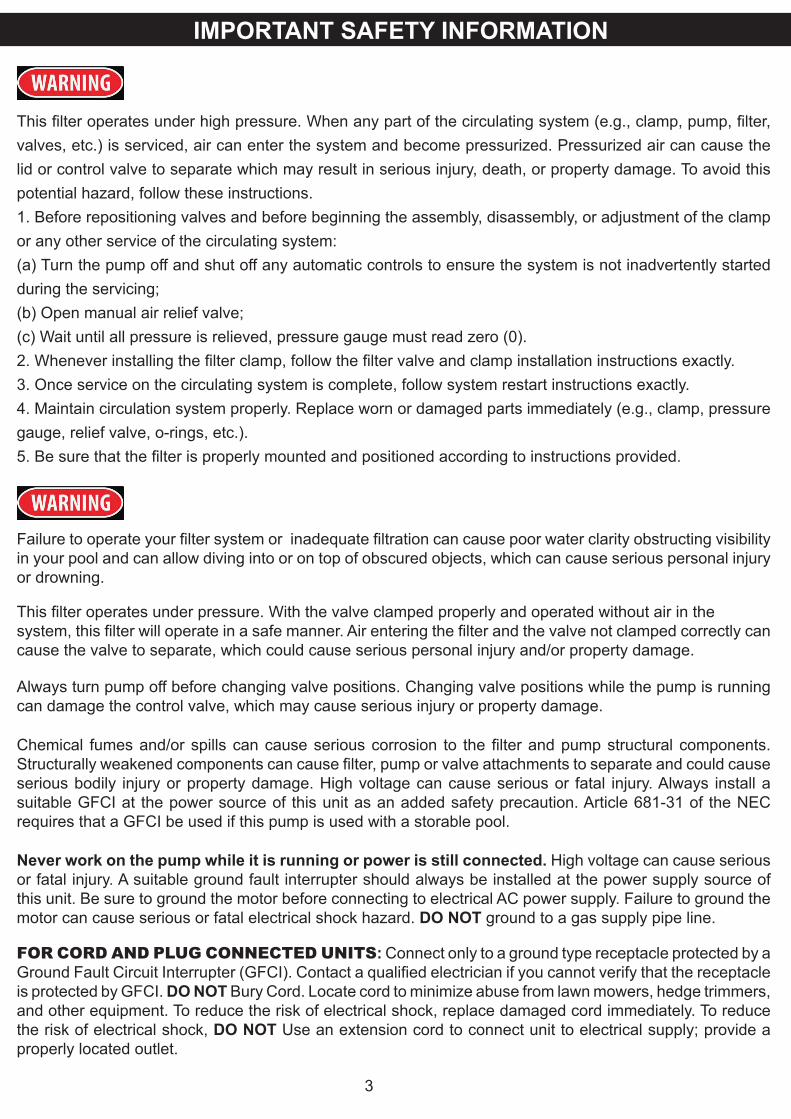
This filter operates under high pressure. When any part of the circulating system (e.g., clamp, pump, filter, valves, etc.) is serviced, air can enter the system and become pressurized. Pressurized air can cause the lid or control valve to separate which may result in serious injury, death, or property damage. To avoid this potential hazard, follow these instructions.1. Before repositioning valves and before beginning the assembly, disassembly, or adjustment of the clamp or any other service of the circulating system:(a) Turn the pump off and shut off any automatic controls to ensure the system is not inadvertently started during the servicing;(b) Open manual air relief valve;(c) Wait until all pressure is relieved, pressure gauge must read zero (0).2. Whenever installing the filter clamp, follow the filter valve and clamp installation instructions exactly.3. Once service on the circulating system is complete, follow system restart instructions exactly.4. Maintain circulation system properly. Replace worn or damaged parts immediately (e.g., clamp, pressure gauge, relief valve, o-rings, etc.).5. Be sure that the filter is properly mounted and positioned according to instructions provided.
Failure to operate your filter system or inadequate filtration can cause poor water clarity obstructing visibility in your pool and can allow diving into or on top of obscured objects, which can cause serious personal injury or drowning.
This filter operates under pressure. With the valve clamped properly and operated without air in thesystem, this filter will operate in a safe manner. Air entering the filter and the valve not clamped correctly can cause the valve to separate, which could cause serious personal injury and/or property damage.
Always turn pump off before changing valve positions. Changing valve positions while the pump is running can damage the control valve, which may cause serious injury or property damage.
Chemical fumes and/or spills can cause serious corrosion to the filter and pump structural components. Structurally weakened components can cause filter, pump or valve attachments to separate and could cause serious bodily injury or property damage. High voltage can cause serious or fatal injury. Always install a suitable GFCI at the power source of this unit as an added safety precaution. Article 681-31 of the NEC requires that a GFCI be used if this pump is used with a storable pool.
Never work on the pump while it is running or power is still connected. High voltage can cause serious or fatal injury. A suitable ground fault interrupter should always be installed at the power supply source of this unit. Be sure to ground the motor before connecting to electrical AC power supply. Failure to ground the motor can cause serious or fatal electrical shock hazard. DO NOT ground to a gas supply pipe line.
FOR CORD AND PLUG CONNECTED UNITS: Connect only to a ground type receptacle protected by a Ground Fault Circuit Interrupter (GFCI). Contact a qualified electrician if you cannot verify that the receptacle is protected by GFCI. DO NOT Bury Cord. Locate cord to minimize abuse from lawn mowers, hedge trimmers, and other equipment. To reduce the risk of electrical shock, replace damaged cord immediately. To reduce the risk of electrical shock, DO NOT Use an extension cord to connect unit to electrical supply; provide a properly located outlet.
4
SAND FILTRATION WORKING PRINCIPLEIncoming water from the piping system is automatically directed by the multi-port valve to the top of the filter bed. As the water is pumped through the filter sand, dirt and debris are trapped by the filter bed, and filtered out. The filter water is returned from the bottom of the filter tank., through the multi-port and back through the piping system .
PREPARATION BEFORE INSTALLATION1. Position the filter as close to the swimming pool / spa as possible.
2. The filter should be placed on a level concrete slab, very firm ground, or equivalent. Ensure that the ground will not subside to prevent any strain to the attached plumbing.
3. Position the filter so that the piping connections, Multi-Port Valve and winter drain is convenient and accessible for operation, servicing and winterizing.4. Ensure that the compliance label is facing the front to allow easy identification in the case ofservice difficulties.
INSTALLATION
INSTALLATIONWARNING: This product should be installed and serviced only by a qualified professional.
1. Put the filter tank on the base. Turn the filter tank to the right to tighten it. Position the outlet drain plugso it is facing outside for easy operation.
2. Before filling the filter media into the filter vessel, do a visual check of the laterals. Look for broken orloose laterals. Replace if necessary. The laterals of side-mount valve sand filter are all installed.
3. Match the Raised Point of the laterals to Folding Umbrella lateral holder, insert the laterals and turn90º clockwise. Listen for a sound to confirm the lateral is in place.
4. Make sure the air release hose is running along side the body of the lateral holder. One end of theair release hose MUST be out of the sand. DO NOT bury the air release hose in the sand.
5. To eliminate stress on the laterals, fill the filter vessel with enough water to provide a cushioningeffect when the filter sand is poured in.
6. Use Sand Shield to protect the filter top mount and make sure the central stem pipe has been fully covered.
7. Carefully pour the exact amount of sand into the filter vessel. DO NOT allow sand to go into the stem pipe. DO NOT damage the filter top mount or it can cause a leak.
8. Put the O-Ring on the top mount valve and then connect the valve on the filter vessel. Thestem pipe should be straight and aligned with the top mount valve. Tighten the flange clamp on thevalve. NOTE: The flange clamp should be in place and tight or it could cause injuries.
9. To connect the pump to the base, use the screws from the pump hardware pack.
10. Adjust the valve position. The pressure hose connects to the pump output/input valve.
11. The other two connection ends of the valve connect to the swimming pool and the drain outlet hose.
INSTALLATION
5
INSTALLATION NOTES1. Make sure the filter is operating under the working pressure and using a pressure control valve whenthe system is using a booster pump.2. To aid in winterization and maintenance it is recommended that a separate gate valve be installed.3. Minimize the length of pipe and the number of fittings to minimize friction loss to ensure maximumefficiency.4. Connect all plumbing to the Multi-port Valve taking care that all joints are glued or tightened securely to prevent leaking.5. To prevent breakage and damage to the pump and Multi-port Valve, use only pipe sealants specifically formulated for plastics.6. Ensure solvents are not excessively applied to fittings as this could run into O-Rings and create sealing problems.7. DO NOT over tighten fittings or adapters.
MULTI-PORT VALVE INSTALLATIONTop Mount Sand Filters are supplied with a screw down Multi-port Valve. Supplied with the Multi-port Valve are Flange clamp, screws and O-Ring.
1. Screw the barrel unions onto the threaded ports on the Multi-port Valve.
2. When rotating the Multi-port Valve into position on a Top Mount Filter, leave some leeway for betteralignment of plumbing.
3. Once the Multi-port Valve is in position and the plumbing is aligned, apply the thread tape to the barrel union thread.
4. Using a roll of Teflon tape, wrap the Teflon tape around the thread (tail) of the barrel union in a clockwise direction.
5. Screw the barrel union into the thread of the Multi-port Valve and hand tighten. The barrel union should be firmly threaded into the Multi-port Valve and there should be no play between the thread.
6. Once you have done this tighten the barrel union with an appropriate tool until it is tight.
7. Repeat steps until all barrel unions are firmly onto the Multi-port Valve.
8. Glue the plumbing to the Barrel unions and allow 24 hours for glue (solvent) to set before starting the filter.
9. Test the filter and check for leaks around the threads. If leaking occurs disconnect plumbing and repeat the steps 2 to 6 until the leak has stopped.
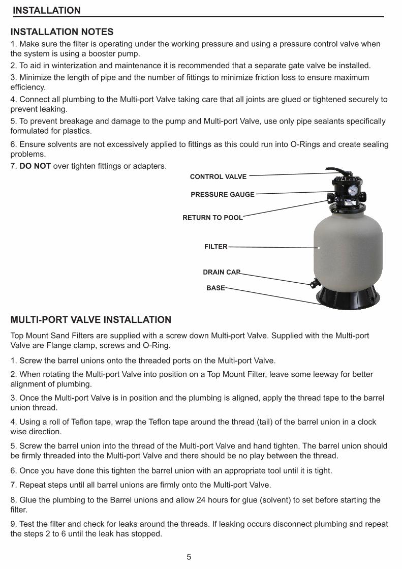
CONTROL VALVE
PRESSURE GAUGE
RETURN TO POOL
FILTER
BASE
DRAIN CAP

INSTALLATION
6
INITIAL STARTUP OF FILTERBe sure correct amount of filter media is in tank and that all connections have been made and are secure. The filter system should be installed, not more than 6 feet above pool water level, on a level concrete slab, very firm ground, or equivalent.1. Loading sand media. Filter sand media is loaded through the top opening of the filter.a. Loosen flange clamp and remove Filter Control Valve (if previously installed).b. Cap internal pipe with sand shield to prevent sand from entering it. Be sure pipe is securely in place in bottom under drain hub.c. We recommend filling tank approximately 1/2 way with water to provide a cushioning effect then the filter sand is poured in. This helps protect the under drain laterals from excessive shock. d. Carefully pour in correct amount and grade of filter sand, as specified on Table 1. (Be sure center piperemains centered in opening). Sand surface should be leveled and should come to within 6” of the top of the filter tank. Remove sand shield from internal pipe.2. Assemble Filter Control Valve to filter tank.a. Loosely pre-assemble both halves of the clamp with one screw and one nut, turning the nut 2 or 3 turns. Do not tighten. Wipe filter flange clean.b. Insert Filter Control Valve (with valve/flange 0-ring in place) into the tank neck, taking care that the center pipe slips into the hole in the bottom of the valve. Install clamp around tank and valve flange and assemble second screw and nut. Tighten just enough so that the valve may be rotated on tank for final positioning.c. Wrap two turns of Teflon pipe sealant tape manufactured for plastic pipe on the ¼” NPT male end of gauge. Carefully screw pressure gauge, into 1/4”NPT tapped hole in valve body. Do not over tighten.d. Connect pump to control valve opening marked PUMP according to instructions. After connections are made, tighten valve flange clamp with screwdriver, tapping around clamp with screwdriver handle to help seat valve flange clamp.3. Make return to pool pipe connection to control valve opening marked RETURN and complete other necessary plumbing connections, suction lines to pump, waste, etc.4. To prevent water leakage, be sure winter drain cap is securely in place and all pipe connections are tight.
BACKWASHING CONDITIONSWARNING: ALL SUCTION AND DISCHARGE VALVES MUST BE OPEN WHEN STARTING THE SYSTEM. FAILURE TO DO SO COULD CAUSE SEVERE PERSONAL INJURY.Once water flow is steady out the waste line, run the pump for at least 2 minutes. The initial back-washing of the filter is recommended to remove any impurities or fine sand particles in the sand media.1. Be sure correct amount of filter sand media is in tank and that all connections have been made and are secure. 2. Depress control valve handle and rotate to BACKWASH* position. (To prevent damage to control valve seal, always depress handle before turning.)3. Prime and start pump according to pump instructions (be sure all suction and return lines are open), allowing the filter tank to fill with water. 4. Turn pump off and set valve to RINSE position. Start pump and operate until water in sight glass is clear about 1/2 to 1 minute. Turn pump off, set valve to FILTER position and restart pump. Your filter is now operating in the normal filter mode, filtering particles from the pool water.5. Adjust pool suction and return valves to achieve desired flow. Check system and filter for water leaks and tighten connections, bolts, nuts, as required.6. Note the initial pressure gauge reading when the filter is clean. (It will vary from pool to pool depending upon the pump and general piping system). As the filter removes dirt and impurities from the pool water, the accumulation in the filter will cause the pressure to rise and flow to diminish. When the pressure gauge reading is 8-10 PSI (0.55-0.69 BAR) higher than the initial “clean” pressure you noted, it is time to backwash (clean) the filter (see BACKWASH under Filter Control Valve Functions.) NOTE: During initial clean-up of the pool water it may benecessary to backwash frequently due to the unusually heavy initial dirt load in the water. FILTER—Set valve to FILTER for normal filtering. Also use for regular vacuuming.BACKWASH—For cleaning filter. When filter pressure gauge rises 8-10 PSI (0.55-0.69 BAR) above start-up(clean pressure): Stop the pump, set valve to BACKWASH. Start pump and backwash until water in sight glass is clear. Approximately 2 minutes or less depending on dirt accumulation. Proceed to RINSE.
TROUBLESHOOTING / GUIDES
7
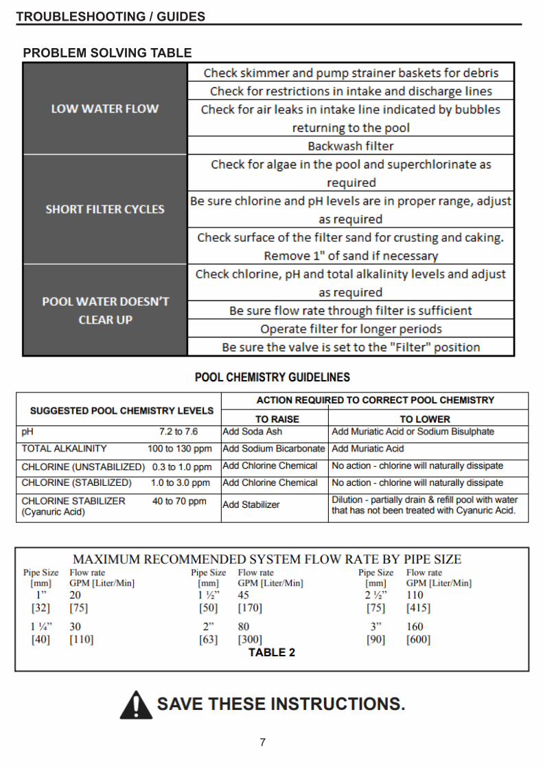
PROBLEM SOLVING TABLE
PLEASE READ THE FOLLOWING CAREFULLY
THE MANUFACTURER AND/OR DISTRIBUTOR HAS PROVIDED THE PARTS LIST AND ASSEMBLY DIAGRAM IN THIS MANUAL AS A REFERENCE TOOL ONLY. NEITHER THE MANUFACTURER OR DISTRIBUTOR MAKES ANY REPRESENTATION OR WARRANTY OF ANY KIND TO THE BUYER THAT HE OR SHE IS QUALIFIED TO MAKE ANY REPAIRS TO THE PRODUCT, OR THAT HE OR SHE IS QUALIFIED TO REPLACE ANY PARTS OF THE PRODUCT. IN FACT, THE MANUFACTURER AND/OR DISTRIBUTOR EXPRESSLY STATES THAT ALL REPAIRS AND PARTS REPLACEMENTS SHOULD BE UNDERTAKEN BY CERTIFIED AND LICENSED TECHNICIANS, AND NOT BY THE BUYER. THE BUYER ASSUMES ALL RISK AND LIABILITY ARISING OUT OF HIS OR HER REPAIRS TO THE ORIGINAL PRODUCT OR REPLACEMENT PARTS THERETO, OR ARISING OUT OF HIS OR HER INSTALLATION OF REPLACEMENT PARTS THERETO.
Note: Some parts are listed and shown for illustration purposes only and are not available individually as replacement parts.
Record Product’s Serial Number Here:Note: If product has no serial number, record month and year of purchase instead.
8
FEATURES
FEATURES AND SPECIFICATIONS
Flange clamp design allows 360 degree rotation of valve to simplify plumbingUnitized, corrosion-proof filter tank7 position Vari-Flo control valve with easy-to-use lever-action handleLarge pressure sand/water drain
Umbrella-fold self cleaning laterals
Max Water Temp 105F
Holds to 175lbs of sand
Max filter 24000 gallon per day (10 hr)
Max pressure 50ps
This pool sand filter is ideal for most in ground and above ground pools for filtering sand and clearing the water. It is able to apply for several water feature including fish ponds, fountains, water gardens. It features flange clamp design providing 360 degree rotation of valve for simplify plumbing.