Embed Size (px)
Citation preview
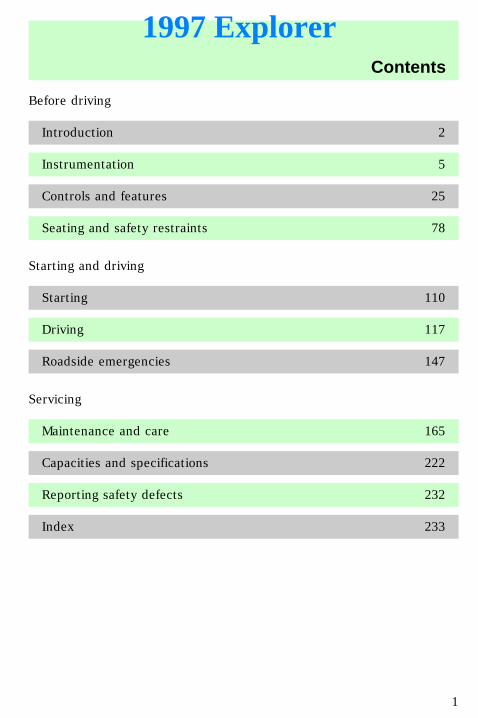
Before driving
Introduction 2
Instrumentation 5
Controls and features 25
Seating and safety restraints 78
Starting and driving
Starting 110
Driving 117
Roadside emergencies 147
Servicing
Maintenance and care 165
Capacities and specifications 222
Reporting safety defects 232
Index 233
Contents
1
1997 Explorer
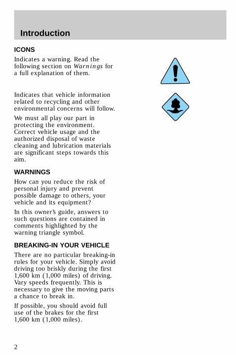
ICONSIndicates a warning. Read thefollowing section on Warnings fora full explanation of them.
Indicates that vehicle informationrelated to recycling and otherenvironmental concerns will follow.
We must all play our part inprotecting the environment.Correct vehicle usage and theauthorized disposal of wastecleaning and lubrication materialsare significant steps towards thisaim.
WARNINGSHow can you reduce the risk ofpersonal injury and preventpossible damage to others, yourvehicle and its equipment?
In this owner’s guide, answers tosuch questions are contained incomments highlighted by thewarning triangle symbol.
BREAKING-IN YOUR VEHICLEThere are no particular breaking-inrules for your vehicle. Simply avoiddriving too briskly during the first1,600 km (1,000 miles) of driving.Vary speeds frequently. This isnecessary to give the moving partsa chance to break in.
If possible, you should avoid fulluse of the brakes for the first1,600 km (1,000 miles).
com_icons.01
com_warn.01
com_breaking_vehicle.01
Introduction
2
From 1,600 km (1,000 miles)onwards you can graduallyincrease the performance of yourvehicle up to the permittedmaximum speeds.
INFORMATION ABOUT THISGUIDEThe information found in thisguide was in effect at the time ofprinting. Ford may change thecontents without notice andwithout incurring obligation.
SPECIAL NOTICES
Notice to owners of utility typevehiclesBefore you drive your vehicle,please read this owner’s guidecarefully. Your vehicle is not apassenger car. As with othervehicles of this type, failure tooperate this vehicle correctly mayresult in loss of control or anaccident. Be sure to read ControlTrac – Automatic Four–WheelDrive System (if equipped) in theDriving chapter as well as thespecial “Four Wheeling”supplement included with AWDand 4WD vehicles.
Using your vehicle as anambulance
Do not use this vehicle asan ambulance.
com_info_guide.01
uno_special_title
uno_notice_utility
uno_ambulance
uno_snowplow
Introduction
3
Using your vehicle as asnowplow
Do not use this vehicle forsnowplowing.
Introduction
4
0
1
2
34
5 6
H
C
F
E
OFF
20
10
30
4050 60 70
80
90
110
200
0 0 0 0 0 0
o o o o
10020
40
6080 100 120
140
160
180
UNLEADEDFUEL ONLY
RSM
SETACC
COASTOFF
ON
SRS
H
H
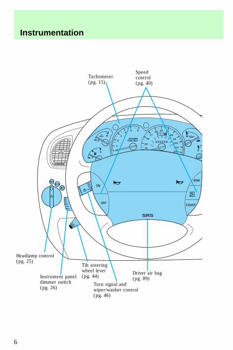
Speedcontrol(pg. 40)
Tachometer(pg. 15)
Driver air bag(pg. 89)
Turn signal andwiper/washer control(pg. 46)
Instrument paneldimmer switch(pg. 26)
Headlamp control(pg. 25)
Tilt steeringwheel lever(pg. 44)
Instrumentation
6
* if equipped
HI
LO OFF
REW1
FF2
SIDE 1-23
FM 1
VOL – PUSH ON
AMFM BASS TREB BAL FADE
AUTOSET
CLK
SEEK
TUNEDISCS
SCAN
4
DOLBY SYSTEM
EJ TAPE CD
COMP5
SHUFFLE6
PUSH
ODON/OFF
Rear wiper/washercontrol (pg. 37)
Fog lampcontrol*(pg. 27)
Electronic soundsystem; refer toAudio Guide (pg. 36)
Climate controls(pg. 28)
Gearshift (includesoverdrive button)(pg. 121)
Instrumentation
7
INSTRUMENT CLUSTERLIGHTS AND CHIMES
Speed control (if equipped)Illuminates when either the SETACC or RSM switches are pressedand remains illuminated until thespeed control is either disengagedor turned off.
O/D off indicatorO/DOFF illuminates when theTransmission Control Button onthe end of the gearshift lever ispressed and the D (Overdrive)mode is turned off.O/DOFF indicates the status of thetransmission and may flash steadilyif a malfunction is detected. If theflashing persists, have yourtransmission serviced by yourdealer or qualified servicetechnician as soon as possible.
If the condition persists, yourtransmission may be damaged.
C
0
1
2
34 5 6
RPMx1000ABS
! PBRAKE
CHECKENGINE
DOORAJAR
E
F
H H
H
P R N D 2 1 THEFT
SPEEDCONTROL
4WD
4WDLOW
O/DOFF
L
L
10 MPH
20
5060 70
30
4080
90
km/h
0 0 0
101
001
201
0 0 0 0 0 040
60
80 100120
140
160
18020
SPEEDCONT
O/DOFF
uno_lights_chimes_title
uno_speed_control
uno_od_off
uno_check_engine
Instrumentation
8
Check engineIlluminates when the engine’sEmission Control System requiresservice. It will also illuminate whenthe ignition key is in the Onposition and the engine is Off.
Anti-theft system (if equipped)Illuminates when the anti-theftsystem is arming and flashes whenthe anti-theft system is armed.
Turn signalIlluminates when the left or rightturn signal or the hazard lights areturned on.
Four wheel drive indicator(if equipped)Illuminates when four wheel driveis activated in the high rangemode.
Four wheel drive — low(if equipped)Illuminates when four wheel driveis activated in the low range mode.
CHECKENGINE
THEFT
4WD
4WDLOW
uno_anti-theft_alarm
com_turn_signal.01
uno_four_wheel
uno_4wd_low
uno_door_ajar
Instrumentation
9
Door ajarIlluminates when the ignitionswitch is in the ON or STARTposition and any door or theliftgate is open.
Check gageIlluminates when the key is in theON position and the engine coolanttemperature gauge, the engine oilpressure gauge and the fuel levelgauge need to be checked. Referto Engine coolant temperaturegauge, Engine oil pressure gaugeor Fuel gauge in theInstrumentation chapter for moreinformation.
Charging systemBriefly illuminates when theignition is turned on and theengine is off. The light alsoilluminates when the battery is notcharging properly, requiringelectrical system service.
Fuel resetIlluminates when the ignition keyis turned to the ON position andthe fuel pump shut-off switch hasbeen triggered. For moreinformation, refer to Fuel pumpshut-off switch in the Roadsideemergencies chapter.
DOORAJAR
CHECKGAGE
FUELRESET
uno_check_gage
com_charging_system.01
com_fuel_reset.01
com_safety_belt.01
Instrumentation
10
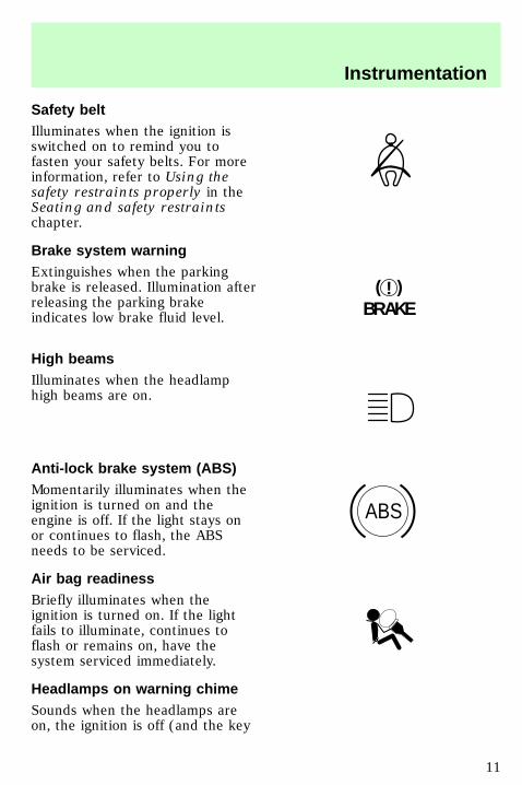
Safety beltIlluminates when the ignition isswitched on to remind you tofasten your safety belts. For moreinformation, refer to Using thesafety restraints properly in theSeating and safety restraintschapter.
Brake system warningExtinguishes when the parkingbrake is released. Illumination afterreleasing the parking brakeindicates low brake fluid level.
High beamsIlluminates when the headlamphigh beams are on.
Anti-lock brake system (ABS)Momentarily illuminates when theignition is turned on and theengine is off. If the light stays onor continues to flash, the ABSneeds to be serviced.
Air bag readinessBriefly illuminates when theignition is turned on. If the lightfails to illuminate, continues toflash or remains on, have thesystem serviced immediately.
Headlamps on warning chimeSounds when the headlamps areon, the ignition is off (and the key
!BRAKE
ABS
uno_brake_system
com_high_beams.01
com_anti-lock_brake.01
com_air_bag.01
uno_headlamps_chime
Instrumentation
11
is not in the ignition) and thedriver’s door is opened.
Key-in-ignition warning chimeSounds when the key is left in theignition in the Off/Lock or Accposition and the driver’s door isopened.
Safety belt warning chimeFor information on the safety beltwarning chime, refer to theSeating and safety restraintschapter.
Supplemental restraint system(SRS) warning chimeFor information on the SRSwarning chime, refer to theSeating and safety restraintschapter.
uno_key_chime
com_safety_chime.01
com_srs_chime.01
uno_gauges_title
Instrumentation
12

INSTRUMENT CLUSTERGAUGES
Engine coolant temperaturegaugeIndicates the temperature of theengine coolant. At normaloperating temperature, the needleremains within the “NORM” area. Ifit enters the red section, theengine is overheating. Switch offthe ignition and let it cool. Refer toChecking and adding enginecoolant in the Maintenance andcare chapter.
Engine oil pressure gaugeThis shows the engine oil pressurein the system. Sufficient pressureexists as long as the needleremains in the “NORM” range.
If the gauge indicates constantlylow pressure at normal enginespeed, refer to Checking andadding engine oil in theMaintenance and care chapter. Ifthe gauge indicates a low pressureand the engine oil level is correct,switch off the engine immediately
0RPMx1000
1
2
34
5 6
- +
H
H
L
L
H
C
F
E
0
20
10
30
4050 60 70
80
90
110
120
0 0 0 0 0 0
o o o o
10020
40
6080 100 120
140
160
180
MPH km/h
H
C
H
L
com_coolant_temperature.01
com_oil_pressure.01
Instrumentation
13
and have your vehicle checked atyour dealership or by a qualifiedtechnician.
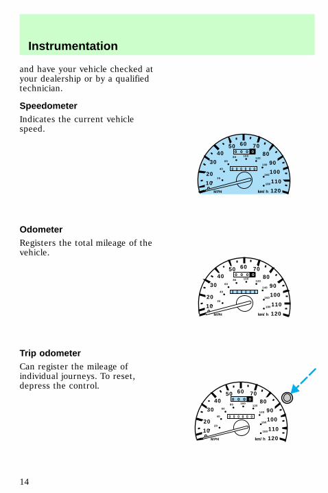
SpeedometerIndicates the current vehiclespeed.
OdometerRegisters the total mileage of thevehicle.
Trip odometerCan register the mileage ofindividual journeys. To reset,depress the control.
0
20
10
30
4050 60 70
80
90
110
120
0 0 0 0 0 0
o o o o
km/hMPH
10020
40
6080 100
120
140
160
180
0
20
10
30
4050 60 70
80
90
110
120
0 0 0 0 0 0
o o o o
100
km/hMPH
20
40
6080 100
120
140
160
180
0
20
10
30
4050 60 70
80
90
110
120
0 0 0 0 0 0
o o o o
100
km/hMPH
20
40
6080 100
120
140
160
180
com_speedometer.01
uno_odometer
uno_trip_odometer
uno_tachometer
Instrumentation
14
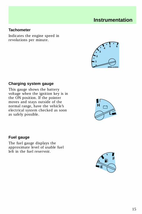
TachometerIndicates the engine speed inrevolutions per minute.
Charging system gaugeThis gauge shows the batteryvoltage when the ignition key is inthe ON position. If the pointermoves and stays outside of thenormal range, have the vehicle’selectrical system checked as soonas safely possible.
Fuel gaugeThe fuel gauge displays theapproximate level of usable fuelleft in the fuel reservoir.
0RPMx1000
1
2
34
5 6
- +H
L
F
E
uno_voltage
uno_fuel_gauge
uno_message_title
Instrumentation
15
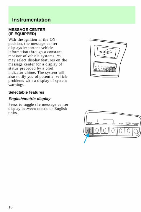
MESSAGE CENTER(IF EQUIPPED)With the ignition in the ONposition, the message centerdisplays important vehicleinformation through a constantmonitor of vehicle systems. Youmay select display features on themessage center for a display ofstatus preceded by a briefindicator chime. The system willalso notify you of potential vehicleproblems with a display of systemwarnings.
Selectable features
English/metric displayPress to toggle the message centerdisplay between metric or Englishunits.
ENGLISHMETRIC RANGE STATUS ECON RESET
SYSTEMCHECK
OIL CHANGERESET
FUEL
ENGLISHMETRIC RANGE STATUS ECON RESET
SYSTEMCHECK
OIL CHANGERESET
FUEL
uno_selectable_message
uno_metric_english
uno_fuel_range
Instrumentation
16
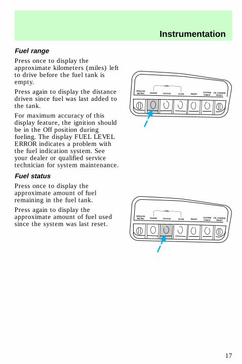
Fuel rangePress once to display theapproximate kilometers (miles) leftto drive before the fuel tank isempty.
Press again to display the distancedriven since fuel was last added tothe tank.
For maximum accuracy of thisdisplay feature, the ignition shouldbe in the Off position duringfueling. The display FUEL LEVELERROR indicates a problem withthe fuel indication system. Seeyour dealer or qualified servicetechnician for system maintenance.
Fuel statusPress once to display theapproximate amount of fuelremaining in the fuel tank.
Press again to display theapproximate amount of fuel usedsince the system was last reset.
ENGLISHMETRIC RANGE STATUS ECON RESET
SYSTEMCHECK
OIL CHANGERESET
FUEL
ENGLISHMETRIC RANGE STATUS ECON RESET
SYSTEMCHECK
OIL CHANGERESET
FUEL
uno_fuel_statusuno_fuel_economy
Instrumentation
17
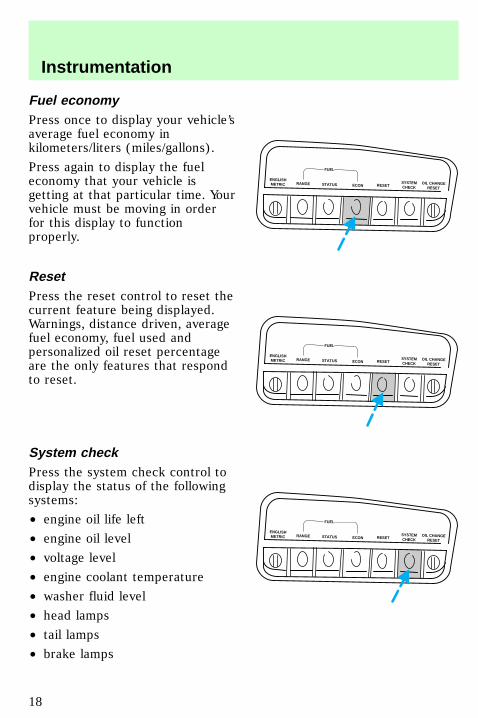
Fuel economyPress once to display your vehicle’saverage fuel economy inkilometers/liters (miles/gallons).
Press again to display the fueleconomy that your vehicle isgetting at that particular time. Yourvehicle must be moving in orderfor this display to functionproperly.
ResetPress the reset control to reset thecurrent feature being displayed.Warnings, distance driven, averagefuel economy, fuel used andpersonalized oil reset percentageare the only features that respondto reset.
System checkPress the system check control todisplay the status of the followingsystems:
• engine oil life left
• engine oil level
• voltage level
• engine coolant temperature
• washer fluid level
• head lamps
• tail lamps
• brake lamps
ENGLISHMETRIC RANGE STATUS ECON RESET
SYSTEMCHECK
OIL CHANGERESET
FUEL
ENGLISHMETRIC RANGE STATUS ECON RESET
SYSTEMCHECK
OIL CHANGERESET
FUEL
ENGLISHMETRIC RANGE STATUS ECON RESET
SYSTEMCHECK
OIL CHANGERESET
FUEL
uno_reset_system
uno_system_check
Instrumentation
18
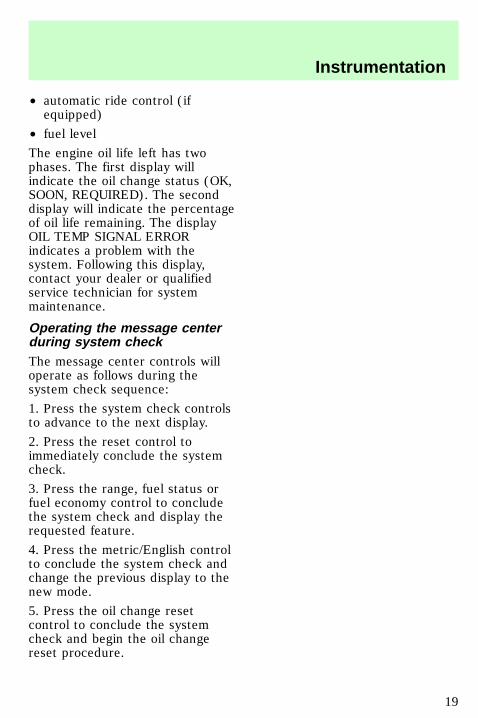
• automatic ride control (ifequipped)
• fuel level
The engine oil life left has twophases. The first display willindicate the oil change status (OK,SOON, REQUIRED). The seconddisplay will indicate the percentageof oil life remaining. The displayOIL TEMP SIGNAL ERRORindicates a problem with thesystem. Following this display,contact your dealer or qualifiedservice technician for systemmaintenance.
Operating the message centerduring system checkThe message center controls willoperate as follows during thesystem check sequence:
1. Press the system check controlsto advance to the next display.
2. Press the reset control toimmediately conclude the systemcheck.
3. Press the range, fuel status orfuel economy control to concludethe system check and display therequested feature.
4. Press the metric/English controlto conclude the system check andchange the previous display to thenew mode.
5. Press the oil change resetcontrol to conclude the systemcheck and begin the oil changereset procedure.
uno_operating_system
uno_oil_life_left
Instrumentation
19
Engine oil life leftThe engine oil left has two phases.The first display will indicate thepercentage the oil change status(OK, SOON, REQUIRED). Thesecond display will indicate thepercentage of oil life remaining.The display OIL TEMP SIGNALERROR indicates a problem withthe system. Following this display,contact your dealer or qualifiedservice technician for systemmaintenance.
Message center warnings
Check air ride systemThis warning message is displayedwhen an air suspension systemfault has been detected. If thiswarning message is displayed whiledriving, safety pull off the road. Ifthe vehicle is loaded beyond therecommended payload, the CHECKAIR RIDE SYSTEM message will bedisplayed. This is a normalcondition if the vehicle isoverloaded. To correct thiscondition:
1. Remove or redistribute the loadaccording to the recommendedmaximum requirements.
2. Turn the ignition from On to Offand back On again.
3. If the warning messagereappears, turn the airsuspension
ENGLISHMETRIC RANGE STATUS ECON RESET
SYSTEMCHECK
OIL CHANGERESET
FUEL
uno_warnings_title
uno_check_air_ride
Instrumentation
20
switch Off and have your vehicleserviced as soon as possible.
Air ride switch offThe air ride suspension switch isoff. Refer to Air suspensionsystem in the Controls andfeatures chapter for moreinformation.
Change oil soonThe engine oil life remaining is 5%or less. After you have the oilchanged, you must reset the M/COil Life Left feature as follows:
1. Turn the ignition to the On orAcc position.
2. Press and hold the OILCHANGE RESET control for fiveseconds. After a successful reset,the message center will display“OIL LIFE RESET TO 100%.”
You may also set a Personalized OilReset Procedure using thefollowing:
1. Turn the ignition to the ON orACC position.
2. Press and hold the OILCHANGE RESET control and pressthe RESET control while thedisplay is counting down the fiveseconds to reset. The display will
ENGLISHMETRIC RANGE STATUS ECON RESET
SYSTEMCHECK
OIL CHANGERESET
FUEL
uno_air_ride
uno_change_oil
Instrumentation
21
change to “START OIL LIFE ATXXX%.”
3. Press the OIL CHANGE RESETcontrol until the displayedpercentage is the Personalized OilReset Percentage you desire.
Check charging systemThe electrical system is notmaintaining a proper voltage. Havethe electrical system checked assoon as safely possible.
Check engine tempThe engine coolant is overheating.Refer to Engine coolanttemperature gauge in theInstrumentation chapter for moreinformation regarding the enginecoolant system.
Check exterior lampsAt least one brake lamp, rear sidemarker or low beam headlamp isburned out. To determine whichlamp is burned out:
1. Turn ignition switch to OFF toreset M/C.
- +H
L
H
C
uno_check_charging_systemuno_check_engine_temp
uno_check_exterior_lamps
Instrumentation
22
2. With the brake lamps, parkinglamps and headlamps off, turn theignition switch to ON or ACC.
3. After M/C briefly illuminates(about two seconds), press thebrake pedal. If “CHECKEXTERIOR LAMPS” is displayed,then a brake lamp is burned out. Ifthis message is not displayed,proceed to the next step.
4. Turn the light switch to theparking lamp positions. If “CHECKEXTERIOR LAMPS” is displayed,then a rear side marker is burnedout. If this message is notdisplayed, proceed to the nextstep.
5. Turn the light switch to theheadlamp position. If “CHECKEXTERIOR LAMPS” is displayed,then a low beam headlamp isburned out.
If you use additional lights, such astrailer lights, or replace bulbs withequipment that is not equal to theoriginal Ford equipment, you may
0
P R N D 2 1
UNLEADEDFUEL ONLY
RPMx1000
1
2
34
5 6
H
C
F
E
RSM
SETACC
COAST
OFF
ONOFF
SRS
OFF
DIM
0
20
10
30
4050 60 70
80
90
110
120
0 0 0 0 0 0
o o o o
km/h
10020
40
6080 100 120
140
160
180
Instrumentation
23
get a false warning or no warningat all.
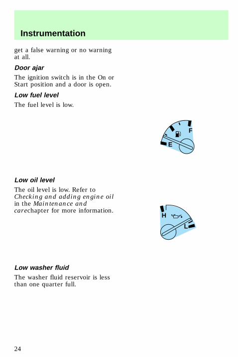
Door ajarThe ignition switch is in the On orStart position and a door is open.
Low fuel levelThe fuel level is low.
Low oil levelThe oil level is low. Refer toChecking and adding engine oilin the Maintenance andcarechapter for more information.
Low washer fluidThe washer fluid reservoir is lessthan one quarter full.
F
E
H
L
uno_door_ajar
uno_low_fuel
uno_low_oil
uno_low_washer
Instrumentation
24
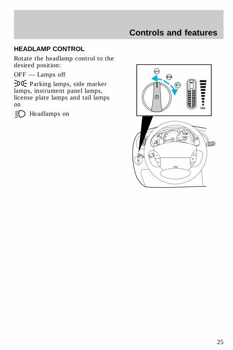
HEADLAMP CONTROLRotate the headlamp control to thedesired position:
OFF — Lamps off
Parking lamps, side markerlamps, instrument panel lamps,license plate lamps and tail lampson
Headlamps on
0
P R N D 2 1
RPMx1000
1
2
34
5 6
H
C
F
E
RSM
SETACC
COAST
OFF
ONOFF
SRS
OFF
DIM
0
20
10
30
4050 60 70
80
90
110
120
0 0 0 0 0 0
o o o o
km/h
10020
40
6080 100 120
140
160
180
uno_headlamp_switch
uno_dimmer_controlControls and features
25
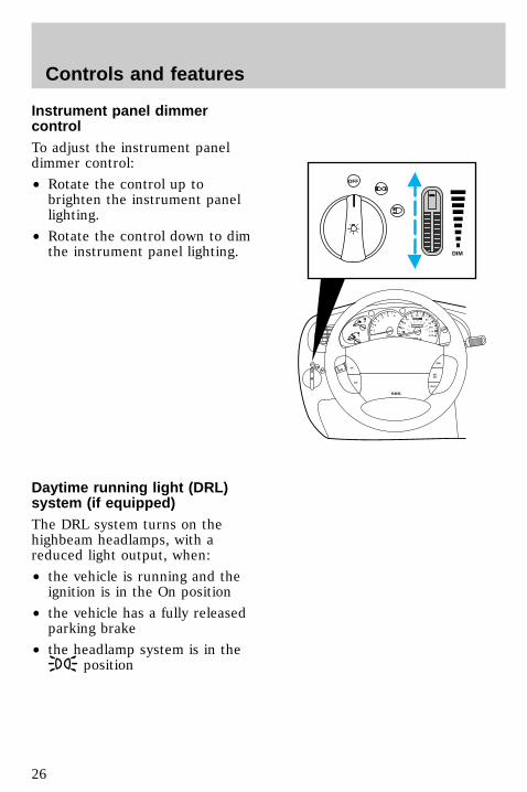
Instrument panel dimmercontrolTo adjust the instrument paneldimmer control:
• Rotate the control up tobrighten the instrument panellighting.
• Rotate the control down to dimthe instrument panel lighting.
Daytime running light (DRL)system (if equipped)The DRL system turns on thehighbeam headlamps, with areduced light output, when:
• the vehicle is running and theignition is in the On position
• the vehicle has a fully releasedparking brake
• the headlamp system is in theposition
0
P R N D 2 1
RPMx1000
1
2
34
5 6
H
C
F
E
RSM
SETACC
COAST
OFF
ONOFF
SRS
OFF
DIM
0
20
10
30
4050 60 70
80
90
110
120
0 0 0 0 0 0
o o o o
km/h
10020
40
6080 100 120
140
160
180
uno_drl_lights
Controls and features
26
The Daytime RunningLight (DRL) system will
not illuminate the tail lamps andparking lamps. Turn on yourheadlamps at dusk. Failure to doso may result in a collision.
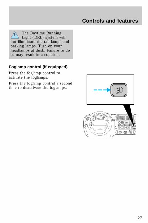
Foglamp control (if equipped)Press the foglamp control toactivate the foglamps.
Press the foglamp control a secondtime to deactivate the foglamps.
0
P R N D 2 1
km/hRPMx1000
1
2
34
5 6
H
C
F
E
RSM
SETACC
COASTOFF
ON
OFF
SRS
HI
LO OFF
*A/C
*MAXA/C
REW1
FF2
SIDE 1-23
FM 1 ST
VOL – PUSH ON
AMFM BASS TREB BAL FADE
AUTOSET
CLK
SEEK
TUNEDISCS
SCAN
4
DOLBY SYSTEM
EJ TAPE CD
COMP5
SHUFFLE6
PUSH
0
20
10
30
4050 60 70
80
90
110
120
0 0 0 0 0 0
o o o o
km/h
10020
40
6080 100 120
140
160
180
uno_foglamp_switch
uno_parking_brake
Controls and features
27
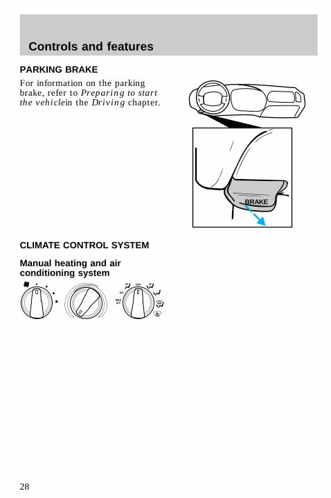
PARKING BRAKEFor information on the parkingbrake, refer to Preparing to startthe vehiclein the Driving chapter.
CLIMATE CONTROL SYSTEM
Manual heating and airconditioning system
BRAKE
OFF
A/C
MAXA/C
uno_climate-control
uno_man-ac
uno_fan_speed
Controls and features
28
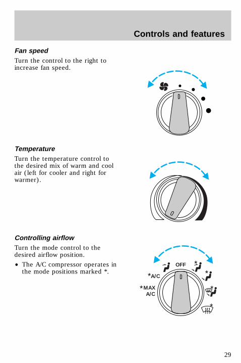
Fan speedTurn the control to the right toincrease fan speed.
TemperatureTurn the temperature control tothe desired mix of warm and coolair (left for cooler and right forwarmer).
Controlling airflowTurn the mode control to thedesired airflow position.
• The A/C compressor operates inthe mode positions marked *.
OFF
A/C
MAXA/C
*
*
**
*
*
uno_temperature_control
uno_air_distribution_dial
uno_max_ac
Controls and features
29

Using MAX A/C modeThe MAX A/C mode recirculatesthe air and directs it to flowthrough the instrument panelvents.
This mode is noisier, but providesquicker cooling than A/C mode.The compressor only functions ifthe outside temperature is above10°C (50°F).
Select MAX A/C for airflowthrough these vents:
Off modeSelect the OFF position for allclimate control functions to cease.The outside inlet door will closeand the fan is shut off.
Drive with the climate controlsystem on (either in heating orA/C mode) to reduce humidity inyour vehicle.
Using A/C modeThe A/C mode directs outsideconditioned air to flow through theinstrument panel vents. The A/Cmode can be used for heating,ventilating or air conditioning. TheA/C compressor only functions inthe A/C mode if the outsidetemperature is above 10°C (50°F).
0
20
10
30
4050 60 70
80
90
110
200
0 0 0 0 0 0
o o o o
km/h
10020
40
6080 100 120
140
160
180
0
P R N D 2 1
RPMx1000
1
2
34
5 6
H
C
F
E
RSM
SETACC
COASTOFF
ONOFF
SRS
HI
LO OFF
*A/C
*MAXA/C
REW1
FF2
SIDE 1-23
FM 1 ST
VOL – PUSH ON
AMFM BASS TREB BAL FADE
AUTOSET
CLK
SEEK
TUNEDISCS
SCAN
4
DOLBY SYSTEM
EJ TAPE CD
COMP5
SHUFFLE6
PUSH
❄
uno_off_mode
uno_ac_control
Controls and features
30
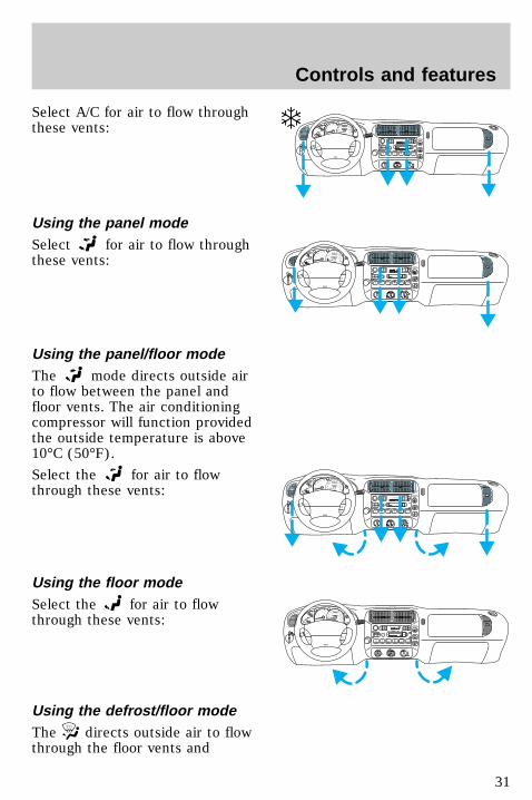
Select A/C for air to flow throughthese vents:
Using the panel modeSelect for air to flow throughthese vents:
Using the panel/floor modeThe mode directs outside airto flow between the panel andfloor vents. The air conditioningcompressor will function providedthe outside temperature is above10°C (50°F).
Select the for air to flowthrough these vents:
Using the floor modeSelect the for air to flowthrough these vents:
Using the defrost/floor modeThe directs outside air to flowthrough the floor vents and
0RPMx1000
1
2
34
5 6
H
C
F
E
0
20
10
30
4050 60 70
80
90
110
200
0 0 0 0 0 0
o o o o
km/h
10020
40
6080 100 120
140
160
180
RSM
SETACC
COASTOFF
ONOFF
SRS
HI
LO OFF
REW1
FF2
SIDE 1-23
FM 1
VOL – PUSH ON
AMFM BASS TREB BAL FADE
AUTOSET
CLK
SEEK
TUNEDISCS
SCAN
4
DOLBY SYSTEM
EJ TAPE CD
COMP5
SHUFFLE6
PUSH
0
P R N D 2 1
RPMx1000
1
2
34
5 6
H
C
F
E
RSM
SETACC
COASTOFF
ONOFF
SRS
HI
LO OFF
*A/C
*MAXA/C
REW1
FF2
SIDE 1-23
FM 1 ST
VOL – PUSH ON
AMFM BASS TREB BAL FADE
AUTOSET
CLK
SEEK
TUNEDISCS
SCAN
4
DOLBY SYSTEM
EJ TAPE CD
COMP5
SHUFFLE6
PUSH
0
20
10
30
4050 60 70
80
90
110
120
0 0 0 0 0 0
o o o o
km/h
10020
40
6080 100 120
140
160
180
0RPMx1000
1
2
34
5 6
H
C
F
E
RSM
SETACC
COASTOFF
ONOFF
SRS
HI
LO OFF
REW1
FF2
SIDE 1-23
FM 1
VOL – PUSH ON
AMFM BASS TREB BAL FADE
AUTOSET
CLK
SEEK
TUNEDISCS
SCAN
4
DOLBY SYSTEM
EJ TAPE CD
COMP5
SHUFFLE6
PUSH
0
20
10
30
4050 60 70
80
90
110
200
0 0 0 0 0 0
o o o o
km/h
10020
40
6080 100 120
140
160
180
uno_panel_mode_climate
uno_pf_mode
uno_floor_mode
uno_df_mode
Controls and features
31
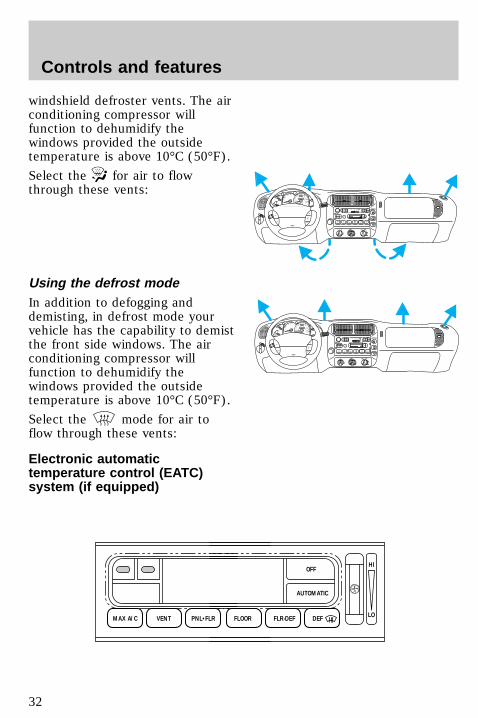
windshield defroster vents. The airconditioning compressor willfunction to dehumidify thewindows provided the outsidetemperature is above 10°C (50°F).
Select the for air to flowthrough these vents:
Using the defrost modeIn addition to defogging anddemisting, in defrost mode yourvehicle has the capability to demistthe front side windows. The airconditioning compressor willfunction to dehumidify thewindows provided the outsidetemperature is above 10°C (50°F).
Select the mode for air toflow through these vents:
Electronic automatictemperature control (EATC)system (if equipped)
0RPMx1000
1
2
34
5 6
H
C
F
E
RSM
SETACC
COASTOFF
ONOFF
SRS
HI
LO OFF
REW1
FF2
SIDE 1-23
FM 1
VOL – PUSH ON
AMFM BASS TREB BAL FADE
AUTOSET
CLK
SEEK
TUNEDISCS
SCAN
4
DOLBY SYSTEM
EJ TAPE CD
COMP5
SHUFFLE6
PUSH
0
20
10
30
4050 60 70
80
90
110
200
0 0 0 0 0 0
o o o o
km/h
10020
40
6080 100 120
140
160
180
0 0RPMx1000
1
2
34
5 6
H
C
F
E
RSM
SETACC
COASTOFF
ONOFF
SRS
HI
LO OFF
REW1
FF2
SIDE 1-23
FM 1
VOL – PUSH ON
AMFM BASS TREB BAL FADE
AUTOSET
CLK
SEEK
TUNEDISCS
SCAN
4
DOLBY SYSTEM
EJ TAPE CD
COMP5
SHUFFLE6
PUSH
0
20
10
30
4050 60 70
80
90
110
200
0 0 0 0 0 0
o o o o
km/h
10020
40
6080 100 120
140
160
180
FLOOR
OFFHI
LO
AUTOMATIC
FLR-DEF DEFMAX A/C VENT PNL•FLR
uno_defrost_mode
uno_eatc_intro_info
Controls and features
32
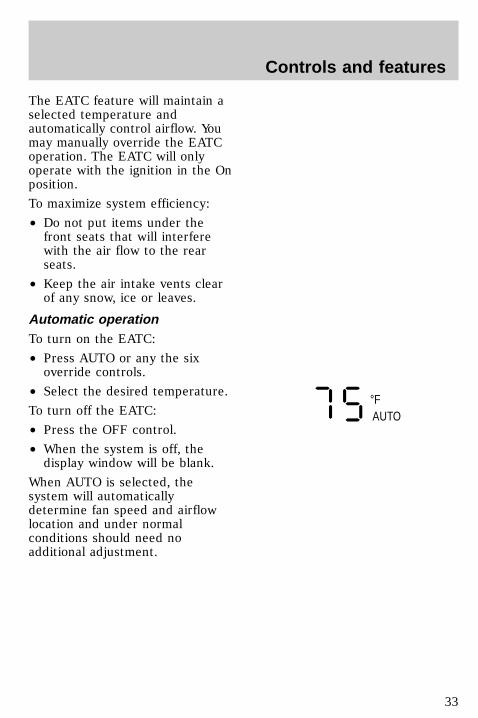
The EATC feature will maintain aselected temperature andautomatically control airflow. Youmay manually override the EATCoperation. The EATC will onlyoperate with the ignition in the Onposition.
To maximize system efficiency:
• Do not put items under thefront seats that will interferewith the air flow to the rearseats.
• Keep the air intake vents clearof any snow, ice or leaves.
Automatic operationTo turn on the EATC:
• Press AUTO or any the sixoverride controls.
• Select the desired temperature.
To turn off the EATC:
• Press the OFF control.
• When the system is off, thedisplay window will be blank.
When AUTO is selected, thesystem will automaticallydetermine fan speed and airflowlocation and under normalconditions should need noadditional adjustment.
°F AUTO
uno_automatic_operation
uno_temperature_select
Controls and features
33
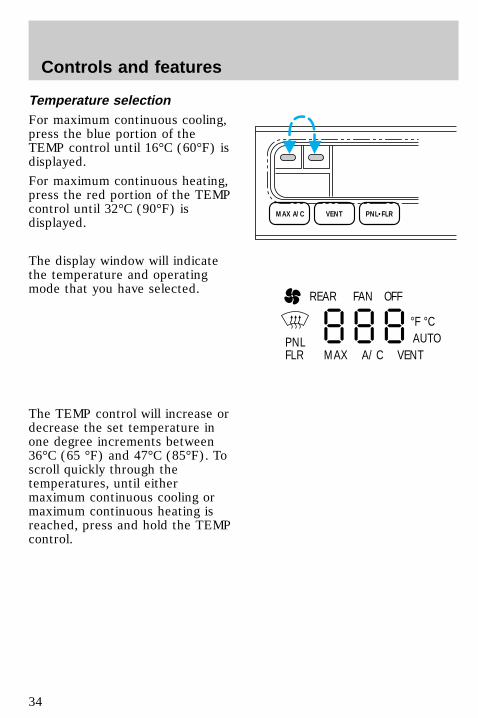
Temperature selectionFor maximum continuous cooling,press the blue portion of theTEMP control until 16°C (60°F) isdisplayed.
For maximum continuous heating,press the red portion of the TEMPcontrol until 32°C (90°F) isdisplayed.
The display window will indicatethe temperature and operatingmode that you have selected.
The TEMP control will increase ordecrease the set temperature inone degree increments between36°C (65 °F) and 47°C (85°F). Toscroll quickly through thetemperatures, until eithermaximum continuous cooling ormaximum continuous heating isreached, press and hold the TEMPcontrol.
MAX A/C VENT PNL•FLR
REAR
PNLFLR
°F °C
MAX A/C VENT
FAN OFF
AUTO
uno_fan_speed
Controls and features
34
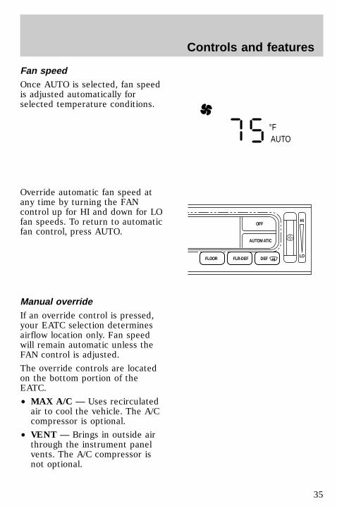
Fan speedOnce AUTO is selected, fan speedis adjusted automatically forselected temperature conditions.
Override automatic fan speed atany time by turning the FANcontrol up for HI and down for LOfan speeds. To return to automaticfan control, press AUTO.
Manual overrideIf an override control is pressed,your EATC selection determinesairflow location only. Fan speedwill remain automatic unless theFAN control is adjusted.
The override controls are locatedon the bottom portion of theEATC.
• MAX A/C — Uses recirculatedair to cool the vehicle. The A/Ccompressor is optional.
• VENT — Brings in outside airthrough the instrument panelvents. The A/C compressor isnot optional.
°F AUTO
FLOOR
OFFHI
LO
AUTOMATIC
FLR-DEF DEF
uno_manual_override
Controls and features
35
• OFF — Outside air is shut outand the fan will not operate.
• PNL & FLR — Directs airthrough the instrument panelregisters and front floor ventand rear air ducts (if equipped).
• FLOOR — Directs airflowthrough the front floor vent andrear air ducts (if equipped).
• FLR & DEF — Directs outsideair through the floor vents anddefroster.
• DEFROST — Directs outsideair through the defroster. Usethis mode to demist and defogthe windshield. In humidweather, select DEF beforestarting your engine to help toprevent windshield fogging.
To toggle between Fahrenheit andCelsius:
• Press the MAX A/C andOFF control at the same
time.
• If the battery is disconnected,the display will revert toFahrenheit.
Servicing the EATCIf the EATC is not operatingproperly, consult your dealer orqualified service technician.
AUDIO SYSTEMRefer to the Audio Guide forinstructions on how to operate theaudio system.
uno_servicing_eatc
com_audio_guide
uno_title_rear_washer
Controls and features
36

Rear window defrosterPress the defroster control to clearthe rear window of thin ice andfog.
The ignition must be in the ONposition to operate the rearwindow defroster.
The defroster turns offautomatically after 10 minutes orwhen the ignition is turned to theOFF position. To manually turn offthe defroster before ten minuteshave passed, push the controlagain.
REAR WINDOW WIPER ANDWASHER (IF EQUIPPED)
WasherPress for rear washer fluidoperation.
0
P R N D 2 1
RPMx1000
1
2
34
5 6
H
C
RSM
SETACC
COAST
OFF
ONOFF
SBS
HI
LO OFF
*A/C
*MAXA/C
REW1
FF2
SIDE 1-23
FM 1 ST
VOL – PUSH ON
AMFM BASS TREB BAL FADE
AUTOSET
CLK
SEEK
TUNEDISCS
SCAN
4
DOLBY SYSTEM
EJ TAPE CD
COMP5
SHUFFLE6
PUSH
0
20
10
30
4050 60 70
80
90
110
120
0 0 0 0 0 0
o o o o
km/h
10020
40
6080 100 120
140
160
180
F
E
uno_rear_washer
uno_rear_wiper
Controls and features
37
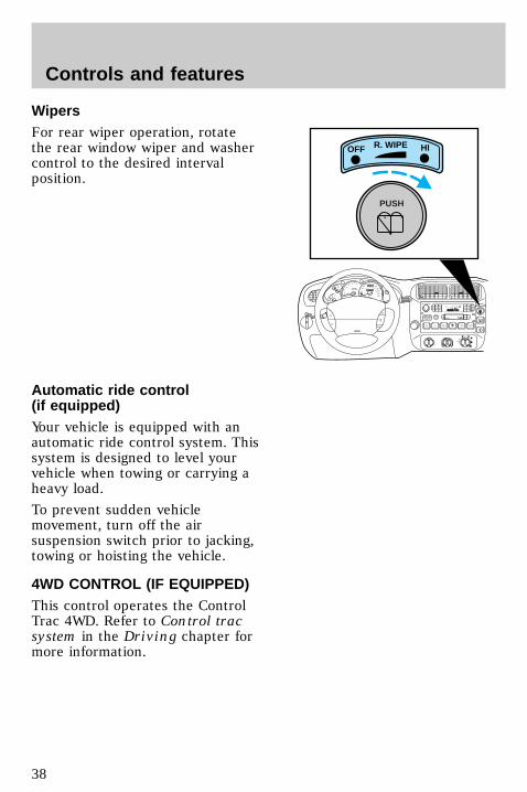
WipersFor rear wiper operation, rotatethe rear window wiper and washercontrol to the desired intervalposition.
Automatic ride control(if equipped)Your vehicle is equipped with anautomatic ride control system. Thissystem is designed to level yourvehicle when towing or carrying aheavy load.
To prevent sudden vehiclemovement, turn off the airsuspension switch prior to jacking,towing or hoisting the vehicle.
4WD CONTROL (IF EQUIPPED)This control operates the ControlTrac 4WD. Refer to Control tracsystem in the Driving chapter formore information.
0
20
10
30
4050 60 70
80
90
110
120
0 0 0 0 0 0
o o o o
km/h
10020
40
6080 100 120
140
160
180
0
P R N D 2 1
UNLEADEDFUEL ONLY
RPMx1000
1
2
34
5 6
H
C
F
E
RSM
SETACC
COAST
OFF
ONOFF
SRS
HI
LO OFF
*A/C
*MAXA/C
REW1
FF2
SIDE 1-23
FM 1 ST
VOL – PUSH ON
AMFM BASS TREB BAL FADE
AUTOSET
CLK
SEEK
TUNEDISCS
SCAN
4
DOLBY SYSTEM
EJ TAPE CD
COMP5
SHUFFLE6
PUSH
OFF HIR. WIPE
PUSH
uno_4wd_switch
uno_fuel_pump_shut_off_ref
Controls and features
38
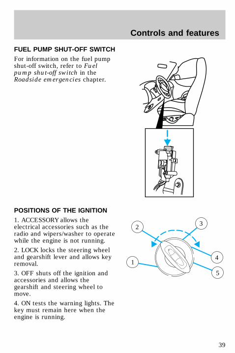
FUEL PUMP SHUT-OFF SWITCHFor information on the fuel pumpshut-off switch, refer to Fuelpump shut-off switch in theRoadside emergencies chapter.
POSITIONS OF THE IGNITION1. ACCESSORY allows theelectrical accessories such as theradio and wipers/washer to operatewhile the engine is not running.
2. LOCK locks the steering wheeland gearshift lever and allows keyremoval.
3. OFF shuts off the ignition andaccessories and allows thegearshift and steering wheel tomove.
4. ON tests the warning lights. Thekey must remain here when theengine is running.
1
2 3
4
5
uno_pst-ignition
Controls and features
39
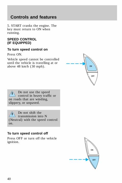
5. START cranks the engine. Thekey must return to ON whenrunning.
SPEED CONTROL(IF EQUIPPED)
To turn speed control onPress ON.
Vehicle speed cannot be controlleduntil the vehicle is travelling at orabove 48 km/h (30 mph).
Do not use the speedcontrol in heavy traffic or
on roads that are winding,slippery, or unpaved.
Do not shift thetransmission into N
(Neutral) with the speed controlon.
To turn speed control offPress OFF or turn off the vehicleignition.
OFF
ON
OFF
ON
uno_speed_control_title
uno_speed-cont-on
uno_turning-cruise-off
Controls and features
40
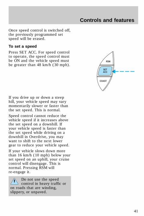
Once speed control is switched off,the previously programmed setspeed will be erased.
To set a speedPress SET ACC. For speed controlto operate, the speed control mustbe ON and the vehicle speed mustbe greater than 48 km/h (30 mph).
If you drive up or down a steephill, your vehicle speed may varymomentarily slower or faster thanthe set speed. This is normal.
Speed control cannot reduce thevehicle speed if it increases abovethe set speed on a downhill. Ifyour vehicle speed is faster thanthe set speed while driving on adownhill in Overdrive, you maywant to shift to the next lowergear to reduce your vehicle speed.
If your vehicle slows down morethan 16 km/h (10 mph) below yourset speed on an uphill, your cruisecontrol will disengage. This isnormal. Pressing RSM willre-engage it.
Do not use the speedcontrol in heavy traffic or
on roads that are winding,slippery, or unpaved.
RSM
SETACC
COAST
uno_setting-a-speed
uno_tap-up-feature
Controls and features
41
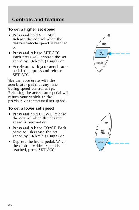
To set a higher set speed• Press and hold SET ACC.Release the control when thedesired vehicle speed is reachedor
• Press and release SET ACC.Each press will increase the setspeed by 1.6 km/h (1 mph) or
• Accelerate with your acceleratorpedal, then press and releaseSET ACC.
You can accelerate with theaccelerator pedal at any timeduring speed control usage.Releasing the accelerator pedal willreturn your vehicle to thepreviously programmed set speed.
To set a lower set speed• Press and hold COAST. Releasethe control when the desiredspeed is reached or
• Press and release COAST. Eachpress will decrease the setspeed by 1.6 km/h (1 mph) or
• Depress the brake pedal. Whenthe desired vehicle speed isreached, press SET ACC.
RSM
SETACC
COAST
RSM
SETACC
COAST
uno_tap-down-feature
uno_resume-feature
Controls and features
42
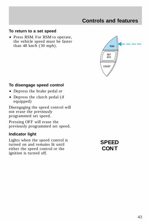
To return to a set speed• Press RSM. For RSM to operate,the vehicle speed must be fasterthan 48 km/h (30 mph).
To disengage speed control• Depress the brake pedal or
• Depress the clutch pedal (ifequipped)
Disengaging the speed control willnot erase the previouslyprogrammed set speed.
Pressing OFF will erase thepreviously programmed set speed.
Indicator lightLights when the speed control isturned on and remains lit untileither the speed control or theignition is turned off.
RSM
SETACC
COAST
SPEEDCONT
uno_disengaging
uno_light
uno_tilt_steer
Controls and features
43
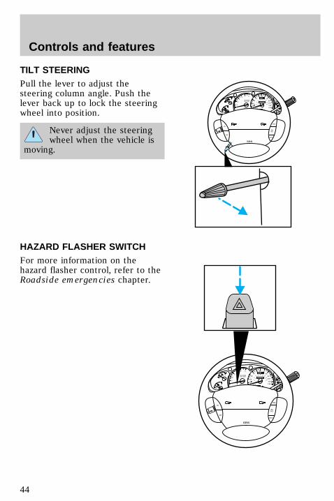
TILT STEERINGPull the lever to adjust thesteering column angle. Push thelever back up to lock the steeringwheel into position.
Never adjust the steeringwheel when the vehicle is
moving.
HAZARD FLASHER SWITCHFor more information on thehazard flasher control, refer to theRoadside emergencies chapter.
0
P R N D 2 1
UNLEADEDFUEL ONLY
RPMx1000
1
2
34
5 6
H
C
F
E
RSM
SETACC
COAST
OFF
ON
SRS
- +
H
H
L
L
0
20
10
30
4050 60 70
80
90
110
120
0 0 0 0 0 0
o o o o
km/h
10020
40
6080 100 120
140
160
180
0
P R N D 2 1
UNLEADEDFUEL ONLY
RPMx1000
1
2
34
5 6
H
C
F
E
RSM
SETACC
COAST
OFF
ON
SRS
- +
H
H
L
L
0
20
10
30
4050 60 70
80
90
110
120
0 0 0 0 0 0
o o o o
km/h
10020
40
6080 100 120
140
160
180
uno_hazarduno_high_beams_flash_to_pass
Controls and features
44
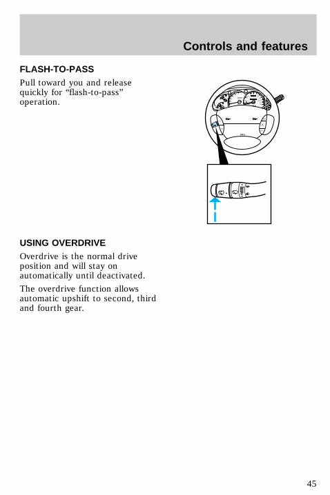
FLASH-TO-PASSPull toward you and releasequickly for “flash-to-pass”operation.
USING OVERDRIVEOverdrive is the normal driveposition and will stay onautomatically until deactivated.
The overdrive function allowsautomatic upshift to second, thirdand fourth gear.
0
P R N D 2 1
UNLEADEDFUEL ONLY
RPMx1000
1
2
34
5 6
H
C
F
E
RSM
SETACC
COAST
OFF
ON
SRS
- +
H
H
L
L
0
20
10
30
4050 60 70
80
90
110
120
0 0 0 0 0 0
o o o o
km/h
10020
40
6080 100 120
140
160
180
uno_overdrive
uno_deactivate_od
Controls and features
45
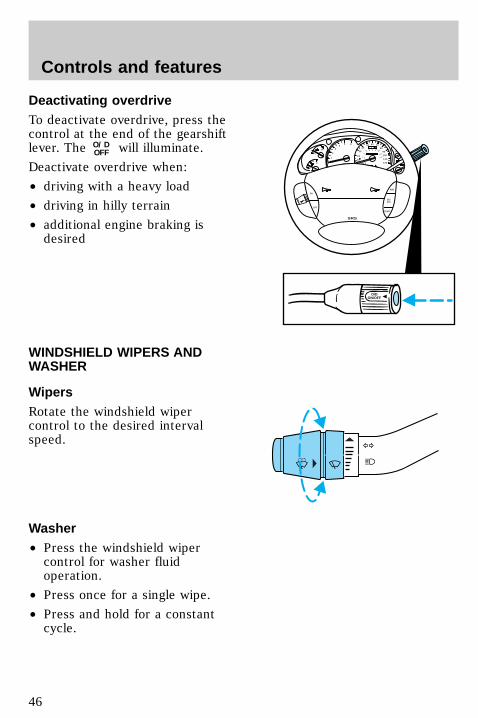
Deactivating overdriveTo deactivate overdrive, press thecontrol at the end of the gearshiftlever. The O/D
OFF will illuminate.
Deactivate overdrive when:
• driving with a heavy load
• driving in hilly terrain
• additional engine braking isdesired
WINDSHIELD WIPERS ANDWASHER
WipersRotate the windshield wipercontrol to the desired intervalspeed.
Washer• Press the windshield wipercontrol for washer fluidoperation.
• Press once for a single wipe.
• Press and hold for a constantcycle.
0
P R N D 2 1
RPMx1000
1
2
34
5 6
H
C
F
E
RSM
SETACC
COAST
OFF
ON
SRS
- +
H
H
L
L
0
20
10
30
4050 60 70
80
90
110
120
0 0 0 0 0 0
o o o o
km/h
10020
40
6080 100 120
140
160
180
O/DON/OFF
uno_title_waher_wiper
uno_wipersuno_washer
uno_speed_dependent_wipers
Controls and features
46
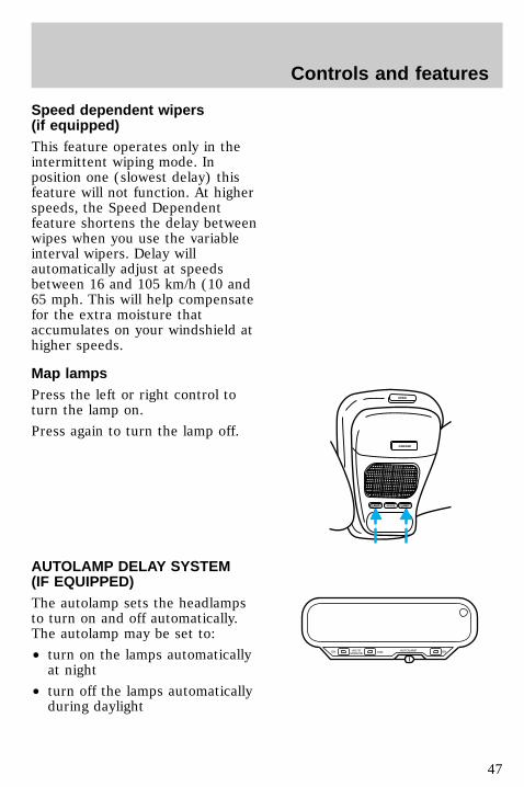
Speed dependent wipers(if equipped)This feature operates only in theintermittent wiping mode. Inposition one (slowest delay) thisfeature will not function. At higherspeeds, the Speed Dependentfeature shortens the delay betweenwipes when you use the variableinterval wipers. Delay willautomatically adjust at speedsbetween 16 and 105 km/h (10 and65 mph. This will help compensatefor the extra moisture thataccumulates on your windshield athigher speeds.
Map lampsPress the left or right control toturn the lamp on.
Press again to turn the lamp off.
AUTOLAMP DELAY SYSTEM(IF EQUIPPED)The autolamp sets the headlampsto turn on and off automatically.The autolamp may be set to:
• turn on the lamps automaticallyat night
• turn off the lamps automaticallyduring daylight
OPEN
GARAGE
MODELAMP LAMP
AUTOMIRROR
ON DIM ONAUTOLAMP
uno_map_lamps
uno_auto-mirror
Controls and features
47
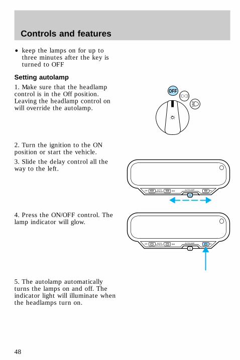
• keep the lamps on for up tothree minutes after the key isturned to OFF
Setting autolamp1. Make sure that the headlampcontrol is in the Off position.Leaving the headlamp control onwill override the autolamp.
2. Turn the ignition to the ONposition or start the vehicle.
3. Slide the delay control all theway to the left.
4. Press the ON/OFF control. Thelamp indicator will glow.
5. The autolamp automaticallyturns the lamps on and off. Theindicator light will illuminate whenthe headlamps turn on.
OFF
AUTOMIRROR
ON DIM ONAUTOLAMP
AUTOMIRROR
ON DIM ONAUTOLAMP
uno_auto-set
uno_auto_dim_mirror
Controls and features
48
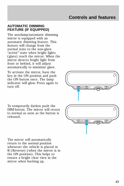
AUTOMATIC DIMMINGFEATURE (IF EQUIPPED)The autolamp/automatic dimmingmirror is equipped with anautomatic dimming feature. Thisfeature will change from thenormal state to the non-glare“active” state when bright lights(glare) reach the mirror. When themirror detects bright light fromfront or behind, it will adjustautomatically to minimize glare.
To activate the mirror, have thekey in the ON position and pushthe ON button once. The lampindicator will glow. Press again toturn off.
To temporarily darken push theDIM button. The mirror will returnto normal as soon as the button isreleased.
The mirror will automaticallyreturn to the normal positionwhenever the vehicle is placed inR (Reverse) (when the mirror is inthe ON position). This helps toensure a bright clear view in themirror when backing up.
AUTOMIRROR
ON DIM ONAUTOLAMP
AUTOMIRROR
ON DIM ONAUTOLAMP
uno_mirror_adjust
Controls and features
49

Adjusting the rearview mirrorThe inside rearview mirror mayadjusted at the two pivot pointsnear the mirror face and thewindshield.
COMPASS (IF EQUIPPED)
Compass displayThe compass reading may beaffected when you drive near largebuildings, bridges, power lines andpowerful broadcast antenna.Magnetic or metallic objects placedin or on the vehicle may also affectcompass accuracy. Adjustmentsmay need to be made to the zoneand calibration of the compass.
OPEN
GARAGE
LAMP MODE LAMP
73° NW
uno_compass-head
uno_compass_temp_display
uno_adjust-zone
Controls and features
50
Compass zone adjustment1. Determine which magnetic zoneyou are in by referring to the zonemap.
2. Press and hold the MODEcontrol until VAR appears in thedisplay, then release. The displayshould show the current zonenumber.
3. Press the MODE control untilthe desired zone number appears.The display will flash and thenreturn to normal operation. Thezone is now updated.
Compass calibration adjustmentPerform this adjustment in anopen area free from steelstructures and high voltage lines:
• Press and hold the MODEcontrol until CAL appears in thedisplay (approximately eightseconds) and release.
• Drive the vehicle slowly (lessthan 5 km/h [3 mph]) in circles
1
2
3
4
56
7 8 9
10
11
12
13
1415
LAMP MODE LAMP
9 VAR
LAMP MODE LAMP
CAL
uno_adjust-calibration
Controls and features
51
until CAL indicator turns off inabout 2–3 complete circles.
MESSAGE CENTER(IF EQUIPPED)This feature displays a variety ofsystem display features. Refer toMessage center in theInstrumentation chapter.
Storage compartment(if equipped)Press the OPEN control to openthe storage compartment. Thedoor will open slightly and can bemoved to full open.
Installing a garage door opener(if equipped)The storage compartment can beconverted to accommodate a
OPEN
GARAGE
LAMP MODE LAMP
MO
DE
LAM
P
LAM
P
OP
EN
uno_message_center
uno_storage_overhead
uno_garage_opener_stow
Controls and features
52
variety of aftermarket garage dooropeners:
• Remove the storage clip fromthe door.
• Place Velcroy hook onto side ofaftermarket transmitter oppositeof actuator control.
• Place transmitter into storagecompartment, control down.
• Place the provided heightadaptors onto the back of theGARAGE control as needed.
• Press the GARAGE control toactivate the transmitter.
uno_moonroof
Controls and features
53
MOON ROOF (IF EQUIPPED)Press and hold the rear portion ofthe moon roof control to open.
Press and hold the front portion ofthe moon roof control to close.
The moon roof has a sliding shadethat can be manually opened orclosed when the glass panel isshut.
To close the shade, pull it towardthe front of the vehicle.
Do not let children playwith the moon roof. They
may seriously hurt themselves.
POWER DOOR LOCKS(IF EQUIPPED)Press U to unlock all doors and Lto lock all doors.
Two-step unlock (if equipped)This feature allows you to unlockall doors of the vehicle with thekey.
1. Unlock the driver door.
MODELAMP LAMP
U L
com_power-doors
uno_2step_unlock
Controls and features
54
2. Repeat unlock procedure withinfour seconds. All doors will unlockwhen the key is returned to thevertical position.
Two-step unlock can be activatedby all outside locks on vehicleswith keyless entry and anti-theft(if equipped).
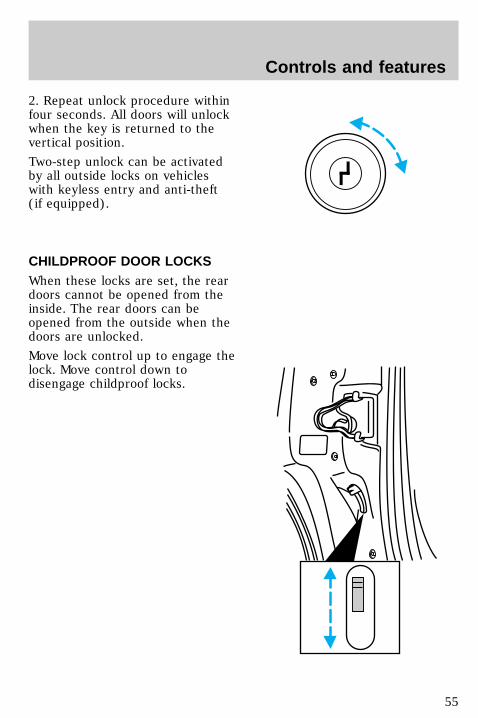
CHILDPROOF DOOR LOCKSWhen these locks are set, the reardoors cannot be opened from theinside. The rear doors can beopened from the outside when thedoors are unlocked.
Move lock control up to engage thelock. Move control down todisengage childproof locks.
uno_child-locks
uno_pwr_windows
Controls and features
55
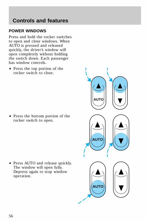
POWER WINDOWSPress and hold the rocker switchesto open and close windows. WhenAUTO is pressed and releasedquickly, the driver’s window willopen completely without holdingthe switch down. Each passengerhas window controls.
• Press the top portion of therocker switch to close.
• Press the bottom portion of therocker switch to open.
• Press AUTO and release quickly.The window will open fully.Depress again to stop windowoperation.
AUTO
AUTO
AUTO
Controls and features
56
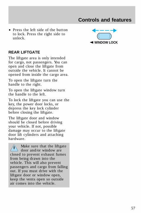
• Press the left side of the buttonto lock. Press the right side tounlock.
REAR LIFTGATEThe liftgate area is only intendedfor cargo, not passengers. You canopen and close the liftgate fromoutside the vehicle. It cannot beopened from inside the cargo area.
To open the liftgate turn thehandle to the right.
To open the liftgate window turnthe handle to the left.
To lock the liftgate you can use thekey, the power door locks, ordepress the key lock cylinderbefore closing the liftgate.
The liftgate door and windowshould be closed before drivingyour vehicle. If not, possibledamage may occur to the liftgatedoor lift cylinders and attachinghardware.
Make sure that the liftgatedoor and/or window are
closed to prevent exhaust fumesfrom being drawn into thevehicle. This will also preventpassengers and cargo from fallingout. If you must drive with theliftgate door or window open,keep the vents open so outsideair comes into the vehicle.
WINDOW LOCK
uno_liftgate_controls
uno_console-heading
Controls and features
57
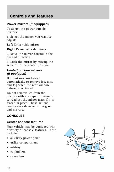
Power mirrors (if equipped)To adjust the power outsidemirrors:
1. Select the mirror you want toadjust:
Left Driver side mirror
Right Passenger side mirror
2. Move the mirror control in thedesired direction.
3. Lock the mirror by moving theselector to the center position.
Heated outside mirrors(if equipped)Both mirrors are heatedautomatically to remove ice, mistand fog when the rear windowdefrost is activated.
Do not remove ice from themirrors with a scraper or attemptto readjust the mirror glass if it isfrozen in place. These actionscould cause damage to the glassand mirrors.
CONSOLES
Center console featuresYour vehicle may be equipped witha variety of console features. Theseinclude:
• auxiliary power point
• utility compartment
• ashtray
• cupholders
• tissue box
uno_center_console_title
Controls and features
58
• utility compartment withcassette/compact disc storageand coinholder
• compact disc changer
• cellular phone
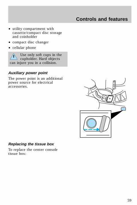
Use only soft cups in thecupholder. Hard objects
can injure you in a collision.
Auxiliary power pointThe power point is an additionalpower source for electricalaccessories.
Replacing the tissue boxTo replace the center consoletissue box:
uno_aux_power_point
uno_tissue_box
Controls and features
59
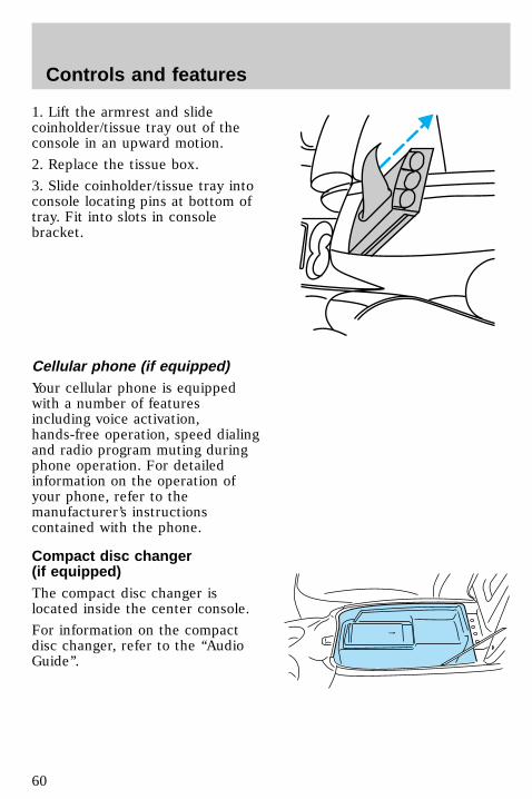
1. Lift the armrest and slidecoinholder/tissue tray out of theconsole in an upward motion.
2. Replace the tissue box.
3. Slide coinholder/tissue tray intoconsole locating pins at bottom oftray. Fit into slots in consolebracket.
Cellular phone (if equipped)Your cellular phone is equippedwith a number of featuresincluding voice activation,hands-free operation, speed dialingand radio program muting duringphone operation. For detailedinformation on the operation ofyour phone, refer to themanufacturer’s instructionscontained with the phone.
Compact disc changer(if equipped)The compact disc changer islocated inside the center console.
For information on the compactdisc changer, refer to the ‘‘AudioGuide’’.
OPEN
uno_cell_phone
uno_rear_console_features
Controls and features
60
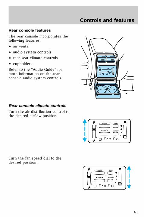
Rear console featuresThe rear console incorporates thefollowing features:
• air vents
• audio system controls
• rear seat climate controls
• cupholders
Refer to the “Audio Guide” formore information on the rearconsole audio system controls.
Rear console climate controlsTurn the air distribution control tothe desired airflow position.
Turn the fan speed dial to thedesired position.
SEEK
– VOLUME + BAND
MEMORY
SEEK
– VOLUME + BAND
MEMORY
uno_climate_controls_rear
Controls and features
61
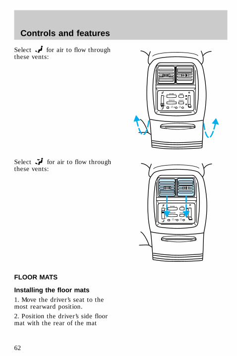
Select for air to flow throughthese vents:
Select for air to flow throughthese vents:
FLOOR MATS
Installing the floor mats1. Move the driver’s seat to themost rearward position.
2. Position the driver’s side floormat with the rear of the mat
SEEK
– VOLUME + BAND
MEMORY
SEEK
– VOLUME + BAND
MEMORY
uno_mats-for-floors
uno_hooking_floor_mat
Controls and features
62
against left (outboard) front edgeof seat track mounting bracket.
3. Use a screwdriver to screwlocator post into vehicle carpeting.Exert pressure while turning topierce the carpeting.
When installed properly, thelocator will not screw down tightly,but will rotate freely.
Usage1. To remove mat, pull up on rearof mat to release from locator post.
2. To re-install mat, align grommetin mat over the locator post andsnap mat into place.
TRUNK MOUNTED CONTROLS
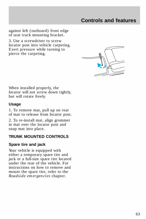
Spare tire and jackYour vehicle is equipped witheither a temporary spare tire andjack or a full-size spare tire locatedunder the rear of the vehicle. Forinstructions on how to remove andmount the spare tire, refer to theRoadside emergencies chapter.
uno_remove-mat
uno_trunk_title
uno_spare_tire
uno_cargo_shade_intro
Controls and features
63
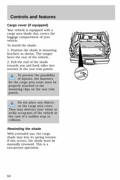
Cargo cover (if equipped)Your vehicle is equipped with acargo area shade that covers theluggage compartment of yourvehicle.
To install the shade:
1. Position the shade in mountingbrackets as shown. The tonguefaces the rear of the vehicle.
2. Pull the end of the shadetowards you and hook sides intonotches in the rear trim panels.
To prevent the possibilityof injuries, the fasteners
for the cargo area cover must beproperly attached to themounting clips on the rear trimpanels.
Do not place any objectson the cargo area cover.
They may obstruct your vision orstrike occupants of the vehicle inthe case of a sudden stop orcollision.
Rewinding the shadeWith extended use, the cargoshade may lose its spring tension.If this occurs, the shade must bemanually rewound. This is atwo-person operation.
uno_rewinding_shade
Controls and features
64
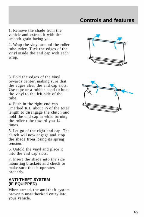
1. Remove the shade from thevehicle and extend it with thesmooth grain facing you.
2. Wrap the vinyl around the rollertube twice. Tuck the edges of thevinyl inside the end cap with eachwrap.
3. Fold the edges of the vinyltowards center, making sure thatthe edges clear the end cap slots.Use tape or a rubber band to holdthe vinyl to the left side of thetube.
4. Push in the right end cap(marked RH) about 1⁄4 of the totallength to disengage the clutch andhold the end cap in while turningthe roller tube toward you 14times.
5. Let go of the right end cap. Theclutch will now engage and stopthe shade from losing its springtension.
6. Unfold the vinyl and place itinto the end cap slots.
7. Insert the shade into the sidemounting brackets and check tomake sure that it operatesproperly.
ANTI-THEFT SYSTEM(IF EQUIPPED)When armed, the anti-theft systemprevents unauthorized entry intoyour vehicle.
com_anti-theft.01
uno_illuminated_entry
Controls and features
65
Illuminated entry system(if equipped)The interior lamps illuminatewhen:
• either front door handle is liftedor
• the remote entry system is usedto unlock the door or sound thepersonal alarm
• or the door is unlocked usingthe key (if equipped withtwo-step unlock.
The system automatically turns offafter 25 seconds or when theignition is turned to the START orACC position.
The inside lights will not turn offif:
• they have been turned on withthe dimmer control or
• any door is open.
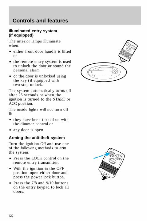
Arming the anti-theft systemTurn the ignition Off and use oneof the following methods to armthe system:
• Press the LOCK control on theremote entry transmitter.
• With the ignition in the OFFposition, open either door andpress the power lock button.
• Press the 7/8 and 9/10 buttonson the entry keypad to lock alldoors.
LOCK
UNLOCKPANIC
PANIC
UNLOCK
LOCK
uno_anti-theft_arming
uno_anti-theft_identifying
Controls and features
66
Identifying an armed anti-theftsystemWhen the system is armed, thewarning light will illuminate for 30seconds. After 30 seconds, thelight will flash.
If the system is armed with thedoors open, the warning light willstay illuminated until all the doorsare closed and then illuminate for30 seconds and begin flashing.
When an unauthorized entryoccurs, the activated system will:
• flash the headlamps, parklampsand the warning light in theinstrument cluster.
• sound the horn.
• prohibit the vehicle fromstarting.
The flashing headlamps andhonking horn will automaticallyshut off after about three minutesand will remain off unless anotherunauthorized entry is attempted.However, the vehicle will not startuntil the system is disarmed.
uno_anti-theft_disar_trig
Controls and features
67
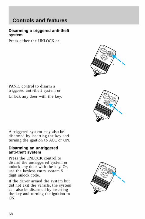
Disarming a triggered anti-theftsystemPress either the UNLOCK or
PANIC control to disarm atriggered anti-theft system or
Unlock any door with the key.
A triggered system may also bedisarmed by inserting the key andturning the ignition to ACC or ON.
Disarming an untriggeredanti-theft systemPress the UNLOCK control todisarm the untriggered system orunlock any door with the key. Or,use the keyless entry system 5digit unlock code.
If the driver armed the system butdid not exit the vehicle, the systemcan also be disarmed by insertingthe key and turning the ignition toON.
LOCK
PANIC
UNLOCK
LOCK
PANIC
UNLOCK
LOCK
PANIC
UNLOCK
uno_anti-theft_disar_untrig
uno_remote_entry
Controls and features
68
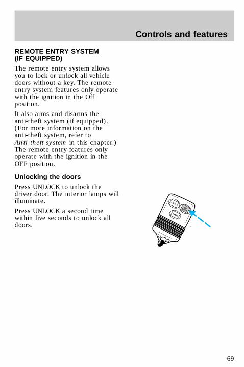
REMOTE ENTRY SYSTEM(IF EQUIPPED)The remote entry system allowsyou to lock or unlock all vehicledoors without a key. The remoteentry system features only operatewith the ignition in the Offposition.
It also arms and disarms theanti-theft system (if equipped).(For more information on theanti-theft system, refer toAnti-theft system in this chapter.)The remote entry features onlyoperate with the ignition in theOFF position.
Unlocking the doorsPress UNLOCK to unlock thedriver door. The interior lamps willilluminate.
Press UNLOCK a second timewithin five seconds to unlock alldoors.
LOCK
PANIC
UNLOCK
com_remote_unlocking.01
uno_remote_locking
Controls and features
69
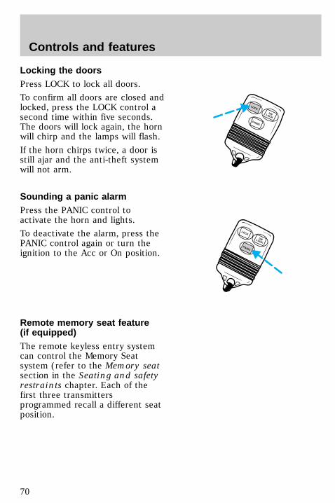
Locking the doorsPress LOCK to lock all doors.
To confirm all doors are closed andlocked, press the LOCK control asecond time within five seconds.The doors will lock again, the hornwill chirp and the lamps will flash.
If the horn chirps twice, a door isstill ajar and the anti-theft systemwill not arm.
Sounding a panic alarmPress the PANIC control toactivate the horn and lights.
To deactivate the alarm, press thePANIC control again or turn theignition to the Acc or On position.
Remote memory seat feature(if equipped)The remote keyless entry systemcan control the Memory Seatsystem (refer to the Memory seatsection in the Seating and safetyrestraints chapter. Each of thefirst three transmittersprogrammed recall a different seatposition.
PANIC
UNLOCK
LOCK
LOCK
PANIC
UNLOCK
uno_remote_panic
uno_remote_memory_seat
Controls and features
70
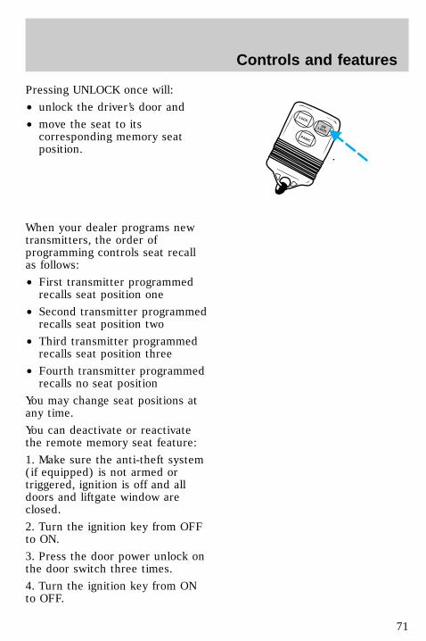
Pressing UNLOCK once will:
• unlock the driver’s door and
• move the seat to itscorresponding memory seatposition.
When your dealer programs newtransmitters, the order ofprogramming controls seat recallas follows:
• First transmitter programmedrecalls seat position one
• Second transmitter programmedrecalls seat position two
• Third transmitter programmedrecalls seat position three
• Fourth transmitter programmedrecalls no seat position
You may change seat positions atany time.
You can deactivate or reactivatethe remote memory seat feature:
1. Make sure the anti-theft system(if equipped) is not armed ortriggered, ignition is off and alldoors and liftgate window areclosed.
2. Turn the ignition key from OFFto ON.
3. Press the door power unlock onthe door switch three times.
4. Turn the ignition key from ONto OFF.
LOCK
PANIC
UNLOCK
Controls and features
71

5. Press the door power unlockswitch three times.
6. Turn the ignition key back toON within 30 seconds of step two.
7. The horn should chirp once. Ifnot, wait 30 seconds and repeatsteps one through six.
8. Press the door power unlockswitch twice.
9. Press the door power lockswitch.
10. The horn will chirp twice if theremote memory seat feature wasdeactivated, three times (two shortchirps followed by a long chirp) ifthe remote memory seat featurewas activated.
11. Turn the ignition key to OFF.
12. The horn will chirp once toconfirm that you activated ordeactivated the remote memoryseat feature.
To reactivate the system, simplyrepeat the instruction fordeactivating. By reentering thecode that deactivates the remotememory seat, the keyless entrysystem reinstates the feature.
The memory seat function willcontinue to work from the doorswitch even when deactivated atthe remote keyless entry module.
Replacing the batteriesThe transmitter is powered by twocoin-type three-volt lithiumbatteries. A decrease in operatingrange can be caused by:
uno_remote_batteries
Controls and features
72
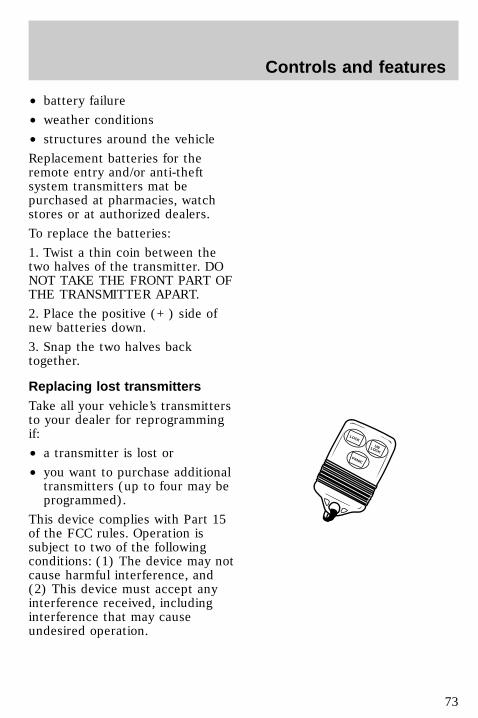
• battery failure
• weather conditions
• structures around the vehicle
Replacement batteries for theremote entry and/or anti-theftsystem transmitters mat bepurchased at pharmacies, watchstores or at authorized dealers.
To replace the batteries:
1. Twist a thin coin between thetwo halves of the transmitter. DONOT TAKE THE FRONT PART OFTHE TRANSMITTER APART.
2. Place the positive (+ ) side ofnew batteries down.
3. Snap the two halves backtogether.
Replacing lost transmittersTake all your vehicle’s transmittersto your dealer for reprogrammingif:
• a transmitter is lost or
• you want to purchase additionaltransmitters (up to four may beprogrammed).
This device complies with Part 15of the FCC rules. Operation issubject to two of the followingconditions: (1) The device may notcause harmful interference, and(2) This device must accept anyinterference received, includinginterference that may causeundesired operation.
LOCK
PANIC
UNLOCK
uno_remote_transmitters
uno_keyless_entry
Controls and features
73
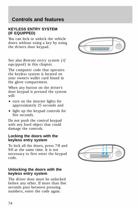
KEYLESS ENTRY SYSTEM(IF EQUIPPED)You can lock or unlock the vehicledoors without using a key by usingthe drivers door keypad.
See also Remote entry system (ifequipped) in this chapter.
The computer code that operatesthe keyless system is located onyour owners wallet card found inthe glove compartment.
When any button on the driver’sdoor keypad is pressed the systemwill:
• turn on the interior lights forapproximately 25 seconds and
• light up the keypad controls forfive seconds.
Do not push the control keypadwith any hard object that coulddamage the controls.
Locking the doors with thekeyless entry systemTo lock all the doors, press 7/8 and9/0 at the same time. It is notnecessary to first enter the keypadcode.
Unlocking the doors with thekeyless entry systemThe driver door must be unlockedbefore any other. If more than fiveseconds pass between pressingnumbers, enter the code again.
1 2 3 4 5 6 7 8 9 0
1 2 3 4 5 6 7 8 9 0
com_keyless_locking.01
uno_keyless_unlocking
Controls and features
74

The system has shut down if thekeypad light is out. If the keylessentry system does not work, usethe key or remote entrytransmitter(s).
1. To unlock the driver door, enterone of the two codes. Afterpressing the fifth number, thedriver door unlocks.
2. To unlock the passenger door(s)and liftgate, press the 3/4 buttonwithin five seconds of unlockingthe driver door.
Programming your own entrycodeThis code does not replace thepermanent code from thedealership.
To program your own code:
1. Select five digits for yourpersonal code.
2. Enter the permanent code thatthe dealership gave you.
3. Within five seconds, press 1/2.
4. Within five seconds of pressing1/2, enter your personal code,pressing each digit within fiveseconds of the previous digit.
You can now use either code. Thesystem remembers only onepersonal code at a time.
To erase your personal code:
1 2 3 4 5 6 7 8 9 0
1 2 3 4 5 6 7 8 9 0
com_keyless_programming.01
Controls and features
75
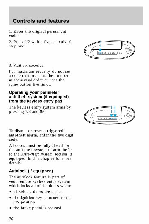
1. Enter the original permanentcode.
2. Press 1/2 within five seconds ofstep one.
3. Wait six seconds.
For maximum security, do not seta code that presents the numbersin sequential order or uses thesame button five times.
Operating your perimeteranti-theft system (if equipped)from the keyless entry padThe keyless entry system arms bypressing 7/8 and 9/0.
To disarm or reset a triggeredanti-theft alarm, enter the five digitcode.
All doors must be fully closed forthe anti-theft system to arm. Referto the Anti-theft system section, ifequipped, in this chapter for moredetails.
Autolock (if equipped)The autolock feature is part ofyour remote keyless entry systemwhich locks all of the doors when:
• all vehicle doors are closed
• the ignition key is turned to theON position
• the brake pedal is pressed
1 2 3 4 5 6 7 8 9 0
1 2 3 4 5 6 7 8 9 0
com_keyless_perimeter.01
uno_keyless_autolock
Controls and features
76
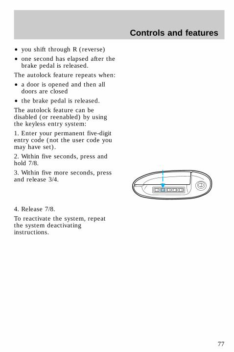
• you shift through R (reverse)
• one second has elapsed after thebrake pedal is released.
The autolock feature repeats when:
• a door is opened and then alldoors are closed
• the brake pedal is released.
The autolock feature can bedisabled (or reenabled) by usingthe keyless entry system:
1. Enter your permanent five-digitentry code (not the user code youmay have set).
2. Within five seconds, press andhold 7/8.
3. Within five more seconds, pressand release 3/4.
4. Release 7/8.
To reactivate the system, repeatthe system deactivatinginstructions.
1 2 3 4 5 6 7 8 9 0
Controls and features
77
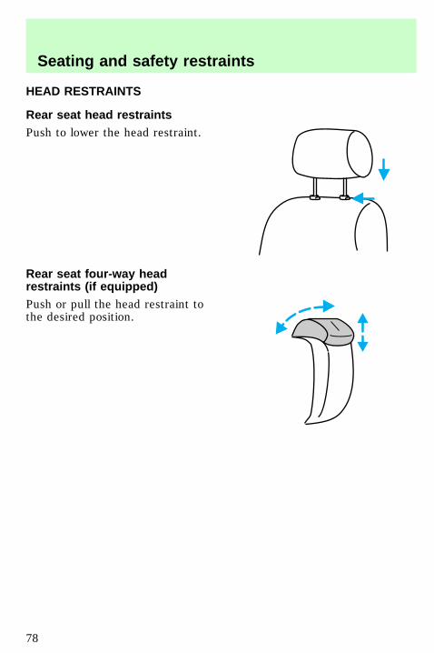
HEAD RESTRAINTS
Rear seat head restraintsPush to lower the head restraint.
Rear seat four-way headrestraints (if equipped)Push or pull the head restraint tothe desired position.
uno_rear_seat_head
uno_four_way_head
uno_seating
Seating and safety restraints
78
SEATING
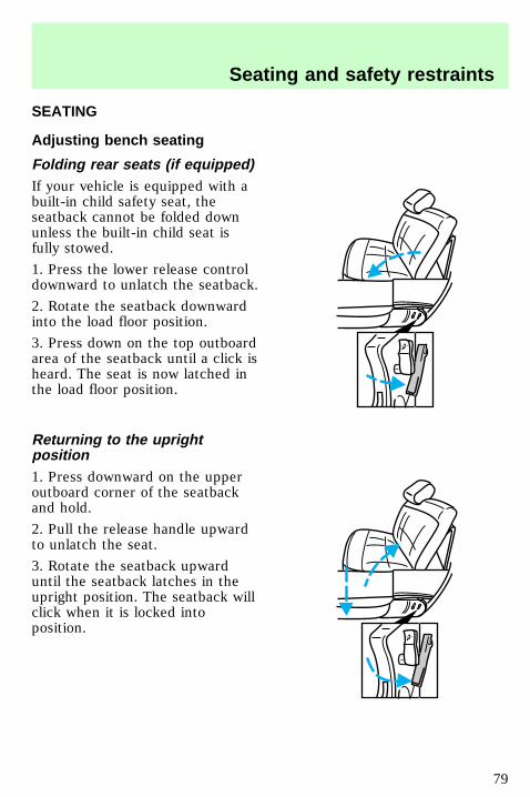
Adjusting bench seating
Folding rear seats (if equipped)If your vehicle is equipped with abuilt-in child safety seat, theseatback cannot be folded downunless the built-in child seat isfully stowed.
1. Press the lower release controldownward to unlatch the seatback.
2. Rotate the seatback downwardinto the load floor position.
3. Press down on the top outboardarea of the seatback until a click isheard. The seat is now latched inthe load floor position.
Returning to the uprightposition1. Press downward on the upperoutboard corner of the seatbackand hold.
2. Pull the release handle upwardto unlatch the seat.
3. Rotate the seatback upwarduntil the seatback latches in theupright position. The seatback willclick when it is locked intoposition.
uno_adjusting_bench
uno_adjust_man_bucket
Seating and safety restraints
79
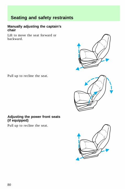
Manually adjusting the captain’schairLift to move the seat forward orbackward.
Pull up to recline the seat.
Adjusting the power front seats(if equipped)Pull up to recline the seat.
uno_adjust_power_seat
Seating and safety restraints
80
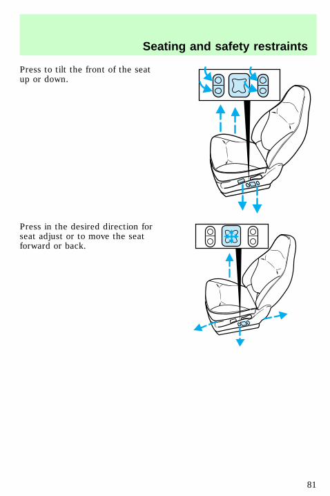
Press to tilt the front of the seatup or down.
Press in the desired direction forseat adjust or to move the seatforward or back.
Seating and safety restraints
81
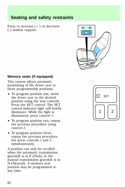
Press to increase (+ ) or decrease(-) lumbar support.
Memory seats (if equipped)This system allows automaticpositioning of the driver seat tothree programmable positions.
• To program position one, movethe driver seat to the desiredposition using the seat controls.Press the SET control. The SETcontrol indicator light will brieflyilluminate. While the light isilluminated, press control 1.
• To program position two, repeatthe previous procedure usingcontrol 2.
• To program position three,repeat the previous procedurebut press controls 1 and 2simultaneously.
A position can only be recalledwhen the automatic transmissiongearshift is in P (Park) or themanual transmission gearshift is inN (Neutral). A memory seatposition may be programmed atany time.
+ –
SET
1 2
uno_remote_seat_controls
uno_seat_belts
Seating and safety restraints
82
SAFETY RESTRAINTS
Important safety restraintsprecautionsThe use of safety belts helps torestrain both driver and passengersin case of a collision. In moststates and Canada, the lawrequires the use of safety belts.
Always drive and ride withyour seatback upright and
the lap belt snug and low acrossthe hips.
Lock the doors of yourvehicle before driving to
lessen the risk of the doorcoming open in a collision.
Cargo should always besecured to prevent it from
shifting and causing damage tothe vehicle or harm topassengers.
To prevent the risk ofinjury, make sure children
sit where they can be properlyrestrained.
uno_safety_res_prec
uno_using_sr_properly
Seating and safety restraints
83
Using safety restraints properly
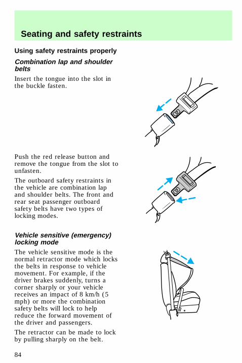
Combination lap and shoulderbeltsInsert the tongue into the slot inthe buckle fasten.
Push the red release button andremove the tongue from the slot tounfasten.
The outboard safety restraints inthe vehicle are combination lapand shoulder belts. The front andrear seat passenger outboardsafety belts have two types oflocking modes.
Vehicle sensitive (emergency)locking modeThe vehicle sensitive mode is thenormal retractor mode which locksthe belts in response to vehiclemovement. For example, if thedriver brakes suddenly, turns acorner sharply or your vehiclereceives an impact of 8 km/h (5mph) or more the combinationsafety belts will lock to helpreduce the forward movement ofthe driver and passengers.
The retractor can be made to lockby pulling sharply on the belt.
uno_comb_lap_sh_belts
uno_man_lock_lap_sh_belt
uno_automatic_locking_mode
Seating and safety restraints
84
Automatic locking modeIn this mode, the shoulder belt isautomatically prelocked; however,the belt will retract to remove anyslack in the shoulder belt.
The automatic locking mode is notavailable on the driver safety belt.
When to use the automaticlocking mode• When a tight lap and shoulderbelt fit is desired.
• Any time a child safety seat isinstalled in the vehicle. Forinformation on the proper use ofa child safety seat, refer toChild safety seats later in thischapter.
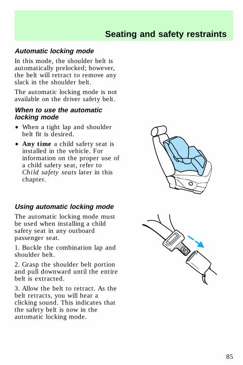
Using automatic locking modeThe automatic locking mode mustbe used when installing a childsafety seat in any outboardpassenger seat.
1. Buckle the combination lap andshoulder belt.
2. Grasp the shoulder belt portionand pull downward until the entirebelt is extracted.
3. Allow the belt to retract. As thebelt retracts, you will hear aclicking sound. This indicates thatthe safety belt is now in theautomatic locking mode.
uno_when_to_use_almode
uno_using_auto_locking_mode
uno_cancel_air
Seating and safety restraints
85
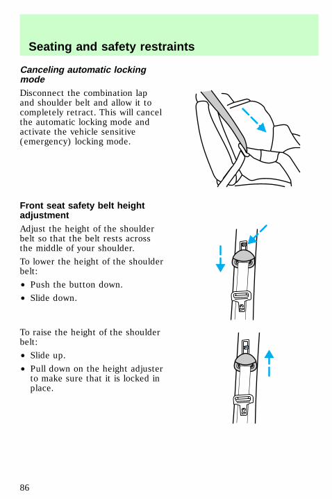
Canceling automatic lockingmodeDisconnect the combination lapand shoulder belt and allow it tocompletely retract. This will cancelthe automatic locking mode andactivate the vehicle sensitive(emergency) locking mode.
Front seat safety belt heightadjustmentAdjust the height of the shoulderbelt so that the belt rests acrossthe middle of your shoulder.
To lower the height of the shoulderbelt:
• Push the button down.
• Slide down.
To raise the height of the shoulderbelt:
• Slide up.
• Pull down on the height adjusterto make sure that it is locked inplace.
uno_front_sbelt_height_adjust
uno_lap_belts
Seating and safety restraints
86
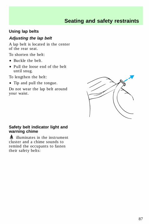
Using lap belts
Adjusting the lap beltA lap belt is located in the centerof the rear seat.
To shorten the belt:
• Buckle the belt.
• Pull the loose end of the beltuntil snug.
To lengthen the belt:
• Tip and pull the tongue.
Do not wear the lap belt aroundyour waist.
Safety belt indicator light andwarning chime
illuminates in the instrumentcluster and a chime sounds toremind the occupants to fastentheir safety belts:
uno_adjusting_lap_belts
uno_indicator_light
Seating and safety restraints
87
Conditions of operation
If . . .. . . Then . . . . .The driver’s safety belt is notbuckled before the ignition keyis turned to On. .
The safety belt indicator illuminatesfor 1-2 minutes and the warningchime sounds for 4- 8 seconds.
The driver’s safety belt isbuckled while the indicatorlight is illuminated and thereminder chime is sounding . ..
The safety belt indicator light andreminder chime turn off.
The driver’s safety belt isbuckled before the ignition keyis turned to On. . .
The safety belt indicator light andreminder chime remain off.
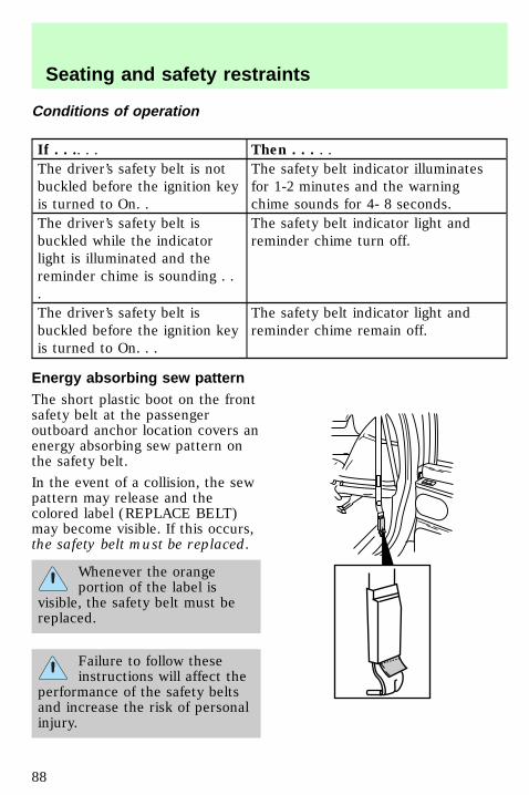
Energy absorbing sew patternThe short plastic boot on the frontsafety belt at the passengeroutboard anchor location covers anenergy absorbing sew pattern onthe safety belt.
In the event of a collision, the sewpattern may release and thecolored label (REPLACE BELT)may become visible. If this occurs,the safety belt must be replaced.
Whenever the orangeportion of the label is
visible, the safety belt must bereplaced.
Failure to follow theseinstructions will affect the
performance of the safety beltsand increase the risk of personalinjury.
uno_sbelt_maint
uno_sbelt_extension
Seating and safety restraints
88
Safety belt extension assemblyThe safety belt may be too shorteven when it is fully extended.Approximately 20 cm (8 inches)may be added to the length of thebelt with a safety belt extension(part # 611C22). Safety beltextensions are available at no costfrom your dealer.
Only use extensions manufacturedby the same supplier as the safetybelt. Manufacturer identification islocated at the end of the webbingon the label.
Do not use the extension tochange the fit of the shoulder beltacross the torso.
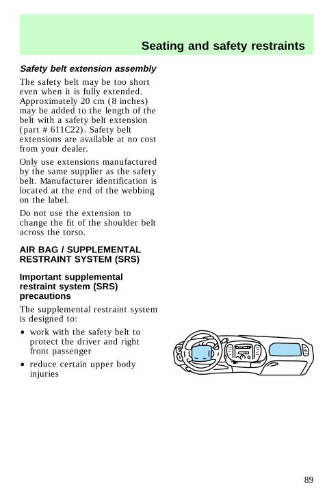
AIR BAG / SUPPLEMENTALRESTRAINT SYSTEM (SRS)
Important supplementalrestraint system (SRS)precautionsThe supplemental restraint systemis designed to:
• work with the safety belt toprotect the driver and rightfront passenger
• reduce certain upper bodyinjuries
uno_air_bags
com_important_precautions.01
Seating and safety restraints
89
Failure to follow theseinstructions will affect the
performance of the safety beltsand increase the risk of personalinjury.
The right front passengerair bag is not designed to
restrain occupants in the frontseating position.
Do not place objects ormount equipment on or
near the air bag covers that maycome into contact with aninflating air bag.
Do not attempt to service,repair, or modify the Air
Bag Supplemental RestraintSystem or its fuses. See yourFord or Lincoln-Mercury dealer.
Children and air bagsFor additional important safetyinformation, read all informationon safety restraints in this guide.
Children should always wear theirsafety belts. Failure to follow theseinstructions may increase the riskof injury in a collision.
com_children.01
Seating and safety restraints
90
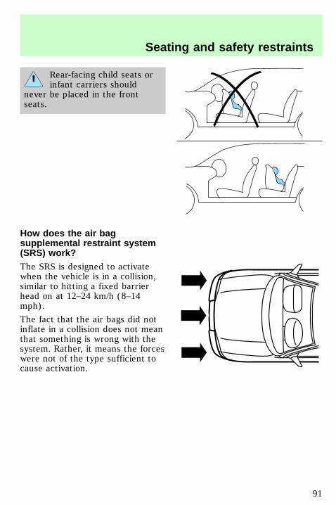
Rear-facing child seats orinfant carriers should
never be placed in the frontseats.
How does the air bagsupplemental restraint system(SRS) work?The SRS is designed to activatewhen the vehicle is in a collision,similar to hitting a fixed barrierhead on at 12–24 km/h (8–14mph).
The fact that the air bags did notinflate in a collision does not meanthat something is wrong with thesystem. Rather, it means the forceswere not of the type sufficient tocause activation.
uno_how_work
Seating and safety restraints
91
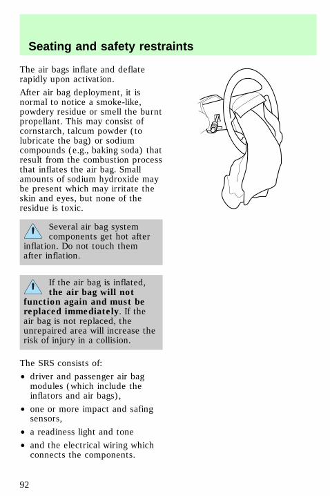
The air bags inflate and deflaterapidly upon activation.
After air bag deployment, it isnormal to notice a smoke-like,powdery residue or smell the burntpropellant. This may consist ofcornstarch, talcum powder (tolubricate the bag) or sodiumcompounds (e.g., baking soda) thatresult from the combustion processthat inflates the air bag. Smallamounts of sodium hydroxide maybe present which may irritate theskin and eyes, but none of theresidue is toxic.
Several air bag systemcomponents get hot after
inflation. Do not touch themafter inflation.
If the air bag is inflated,the air bag will not
function again and must bereplaced immediately. If theair bag is not replaced, theunrepaired area will increase therisk of injury in a collision.
The SRS consists of:
• driver and passenger air bagmodules (which include theinflators and air bags),
• one or more impact and safingsensors,
• a readiness light and tone
• and the electrical wiring whichconnects the components.
Seating and safety restraints
92
The diagnostic module monitors itsown internal circuits and thesupplemental air bag electricalsystem readiness (including theimpact sensors), the system wiring,the air bag system readiness light,the air bag back up power and theair bag ignitors.
Determining if the system isoperationalThe SRS uses a readiness light inthe instrument cluster or a tone toindicate the condition of thesystem. Refer to the Air bagreadiness section in theInstrumentation chapter. Routinemaintenance of the air bag is notrequired.
A difficulty with the system isindicated by one or more of thefollowing:
• The readiness light will eitherflash or stay lit.
• The readiness light will notilluminate immediately afterignition is turned on.
• A group of five beeps will beheard. The tone pattern willrepeat periodically until theproblem and light are repaired.
If any of these things happen, evenintermittently, have the SRSserviced at your dealership or by aqualified technician immediately.Unless serviced, the system maynot function properly in the eventof a collision.
uno_determing_operational
com_disposal.01
Seating and safety restraints
93
Disposal of air bags and air bagequipped vehiclesFor disposal of air bags or air bagequipped vehicles, see your localdealership or qualified technician.Air bags MUST BE disposed of byqualified personnel.
CHILDREN AND SAFETYRESTRAINTS
To prevent the risk ofinjury, make sure children
sit where they can be properlyrestrained.
Do not leave children,unreliable adults, or pets
unattended in your vehicle.
Safety belts and seats canbecome hot in a vehicle
that has been closed up in sunnyweather; they could burn a smallchild. Check seat covers andbuckles before you place a childanywhere near them.
uno_child
Seating and safety restraints
94
It is extremely dangerousto ride in a cargo area,
inside or outside of a vehicle. Ina collision, people riding in theseareas are more likely to beseriously injured or killed. Do notallow people to ride in any areaof your vehicle that is notequipped with seats and safetybelts. Be sure everyone in yourvehicle is in a seat and using asafety belt properly.
Important child restraintprecautionsYou are required by law to usesafety restraints for children in theU.S. and Canada. If small childrenride in your vehicle (generallychildren who are four years old oryounger and who weigh 18 kg [40lbs] or less), you must put them insafety seats made especially forchildren. Check your local andstate or provincial laws for specificrequirements regarding the safetyof children in your vehicle.
Never let a passenger holda child on his or her lap
while the vehicle is moving. Thepassenger cannot protect thechild from injury in a collision.
Always follow the instructions andwarnings that come with any infantor child restraint you might use.
When possible, place children inthe rear seat of your vehicle.
uno_important_precautions
Seating and safety restraints
95
Accident statistics suggest thatchildren are safer when properlyrestrained in the rear seatingpositions than in the front seatingposition.
Children and safety beltsChildren who are too large forchild safety seats (as specified byyour child safety seatmanufacturer) should always wearsafety belts.
Follow all the important safetyrestraint and air bag precautionsthat apply to adult passengers inyour vehicle.
If the shoulder belt portion of acombination lap and shoulder beltcan be positioned so it does notcross or rest in front of the child’sface or neck, the child should wearthe lap and shoulder belt. Movingthe child closer to the center ofthe vehicle may help provide agood shoulder belt fit.
If the shoulder belt cannot beproperly positioned:
• move the child to one of theseats with a lap belt only (ifequipped)
OR
• if the child is the appropriatesize, restrain the child in asafety seat.
Do not leave children,unreliable adults, or pets
unattended in your vehicle.
uno_safety_belts
Seating and safety restraints
96
To improve the fit of lap andshoulder belts on children whohave outgrown child safety seats,Ford recommends use of abelt-positioning booster seat that islabelled as conforming to allFederal motor vehicle safetystandards. Belt-positioning boosterseats raise the child and provide ashorter, firmer seating cushion thatencourages safer seating postureand better fit of lap and shoulderbelts on the child. Abelt-positioning booster should beused if the shoulder belt rests infront of the child’s face or neck, orif the lap belt does not fit snuglyon both thighs, or if the thighs aretoo short to let the child sit all theway back on the seat cushionwhen the lower legs hang over theedge of the seat cushion. You maywish to discuss the special needsof your child with yourpediatrician.
Child safety seats
Carefully follow all of themanufacturer’s instructions
included with the safety seat youput in your vehicle. If you do notinstall and use the safety seatproperly, the child may beinjured in a sudden stop orcollision.
Ford recommends the use of achild safety seat having a toptether strap. Install the child safetyseat in a seating position which iscapable of providing a tether
uno_safety_seats
Seating and safety restraints
97
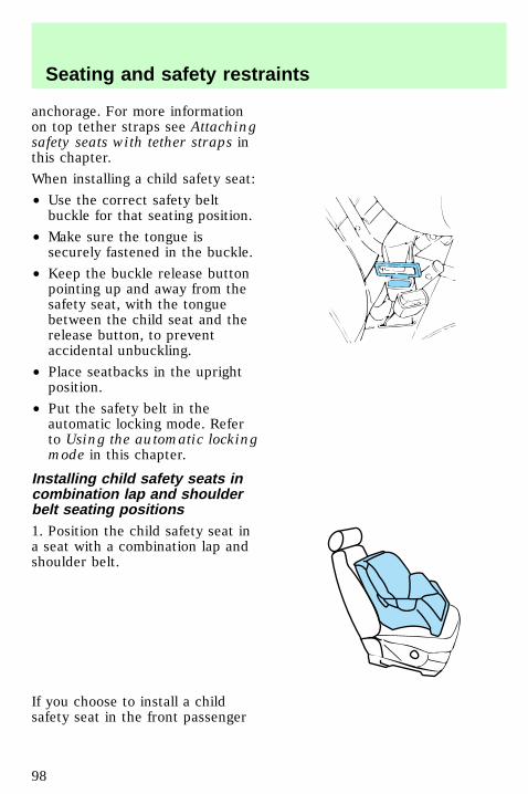
anchorage. For more informationon top tether straps see Attachingsafety seats with tether straps inthis chapter.
When installing a child safety seat:
• Use the correct safety beltbuckle for that seating position.
• Make sure the tongue issecurely fastened in the buckle.
• Keep the buckle release buttonpointing up and away from thesafety seat, with the tonguebetween the child seat and therelease button, to preventaccidental unbuckling.
• Place seatbacks in the uprightposition.
• Put the safety belt in theautomatic locking mode. Referto Using the automatic lockingmode in this chapter.
Installing child safety seats incombination lap and shoulderbelt seating positions1. Position the child safety seat ina seat with a combination lap andshoulder belt.
If you choose to install a childsafety seat in the front passenger
com_installing_seats.01
Seating and safety restraints
98
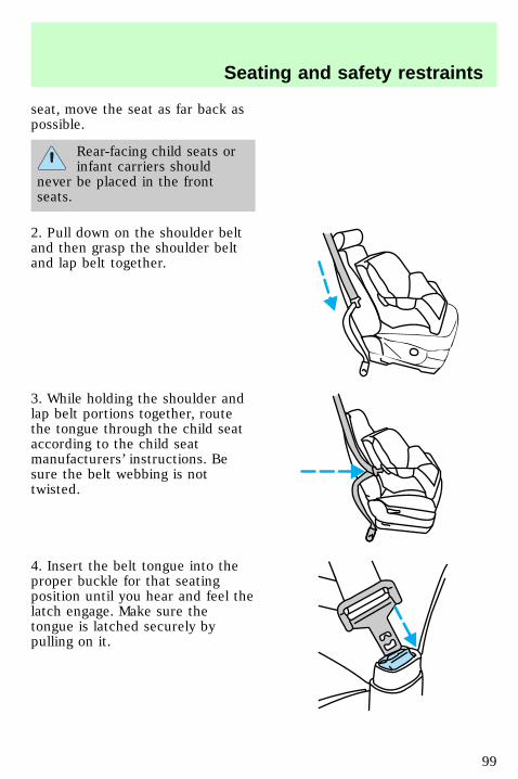
seat, move the seat as far back aspossible.
Rear-facing child seats orinfant carriers should
never be placed in the frontseats.
2. Pull down on the shoulder beltand then grasp the shoulder beltand lap belt together.
3. While holding the shoulder andlap belt portions together, routethe tongue through the child seataccording to the child seatmanufacturers’ instructions. Besure the belt webbing is nottwisted.
4. Insert the belt tongue into theproper buckle for that seatingposition until you hear and feel thelatch engage. Make sure thetongue is latched securely bypulling on it.
Seating and safety restraints
99

5. To put the retractor in theautomatic locking mode, grasp theshoulder portion of the belt andpull downward until all of the beltis extracted and a click is heard.
6. Allow the belt to retract. Thebelt will click as it retracts toindicate it is in the automaticlocking mode.
7. Pull the lap belt portion acrossthe child seat toward the buckleand pull up on the shoulder beltwhile pushing down with knee onthe child seat.
8. Allow the safety belt to retractto remove any slack in the belt.
9. Before placing the child in theseat, forcibly tilt the seat forwardand back to make sure the seat issecurely held in place.
10. Try to pull the belt out of theretractor to make sure theretractor is in the automaticlocking mode (you should not be
Seating and safety restraints
100
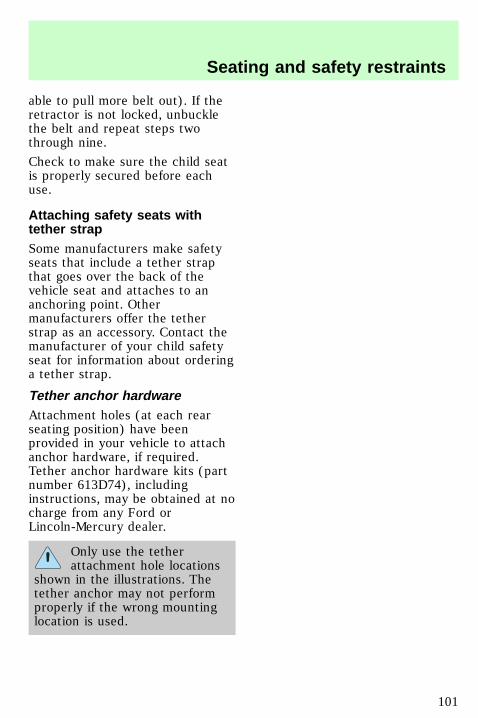
able to pull more belt out). If theretractor is not locked, unbucklethe belt and repeat steps twothrough nine.
Check to make sure the child seatis properly secured before eachuse.
Attaching safety seats withtether strapSome manufacturers make safetyseats that include a tether strapthat goes over the back of thevehicle seat and attaches to ananchoring point. Othermanufacturers offer the tetherstrap as an accessory. Contact themanufacturer of your child safetyseat for information about orderinga tether strap.
Tether anchor hardwareAttachment holes (at each rearseating position) have beenprovided in your vehicle to attachanchor hardware, if required.Tether anchor hardware kits (partnumber 613D74), includinginstructions, may be obtained at nocharge from any Ford orLincoln-Mercury dealer.
Only use the tetherattachment hole locations
shown in the illustrations. Thetether anchor may not performproperly if the wrong mountinglocation is used.
uno_tether_straps
uno_integrated_info
Seating and safety restraints
101
Built-in child seat (if equipped)The rear seat may be equippedwith a built-in child safety seat.This child seat conforms to allfederal and Canadian motor vehiclesafety standards. Read the labelslocated on the child seat cushionand shoulder belt for moreinformation on the built-in childseat.
Use the built-in child seat onlyunder the following conditions:
Child’s age Child’s weight Child’s height
At least one year 10-27 kg (22-60 lb)
Shoulders must bebelow the shoulderharness slots on the
built-in seat.
Children not meeting theserequirements should be secured inan approved aftermarket seat.Refer to Children and infant orchild safety seats in this chapter.
Placing your child in the built-inchild seat
Failure to follow all of theinstructions on the use of
this child restraint system canresult in your child striking thevehicle’s interior during a suddenstop or crash.
uno_placing_child_in_seat
Seating and safety restraints
102
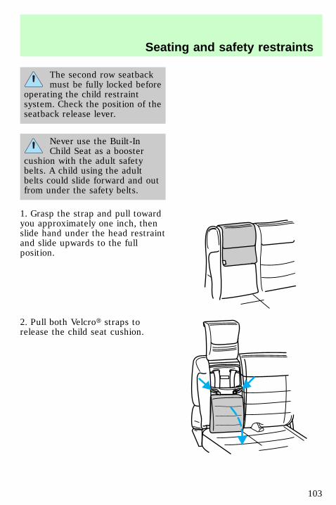
The second row seatbackmust be fully locked before
operating the child restraintsystem. Check the position of theseatback release lever.
Never use the Built-InChild Seat as a booster
cushion with the adult safetybelts. A child using the adultbelts could slide forward and outfrom under the safety belts.
1. Grasp the strap and pull towardyou approximately one inch, thenslide hand under the head restraintand slide upwards to the fullposition.
2. Pull both Velcrot straps torelease the child seat cushion.
Seating and safety restraints
103
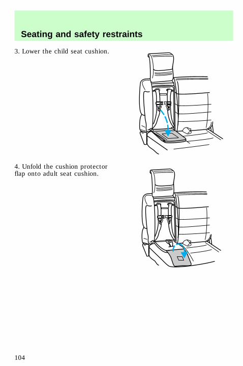
3. Lower the child seat cushion.
4. Unfold the cushion protectorflap onto adult seat cushion.
Seating and safety restraints
104
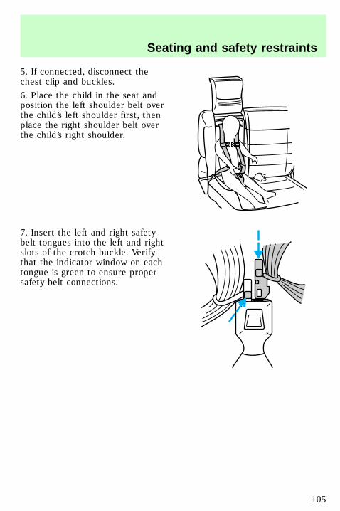
5. If connected, disconnect thechest clip and buckles.
6. Place the child in the seat andposition the left shoulder belt overthe child’s left shoulder first, thenplace the right shoulder belt overthe child’s right shoulder.
7. Insert the left and right safetybelt tongues into the left and rightslots of the crotch buckle. Verifythat the indicator window on eachtongue is green to ensure propersafety belt connections.
Seating and safety restraints
105
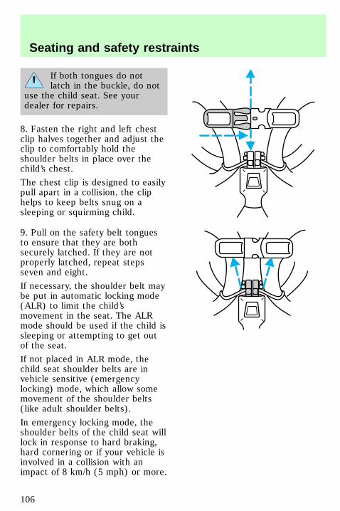
If both tongues do notlatch in the buckle, do not
use the child seat. See yourdealer for repairs.
8. Fasten the right and left chestclip halves together and adjust theclip to comfortably hold theshoulder belts in place over thechild’s chest.
The chest clip is designed to easilypull apart in a collision. the cliphelps to keep belts snug on asleeping or squirming child.
9. Pull on the safety belt tonguesto ensure that they are bothsecurely latched. If they are notproperly latched, repeat stepsseven and eight.
If necessary, the shoulder belt maybe put in automatic locking mode(ALR) to limit the child’smovement in the seat. The ALRmode should be used if the child issleeping or attempting to get outof the seat.
If not placed in ALR mode, thechild seat shoulder belts are invehicle sensitive (emergencylocking) mode, which allow somemovement of the shoulder belts(like adult shoulder belts).
In emergency locking mode, theshoulder belts of the child seat willlock in response to hard braking,hard cornering or if your vehicle isinvolved in a collision with animpact of 8 km/h (5 mph) or more.
uno_alr_in_seat
Seating and safety restraints
106
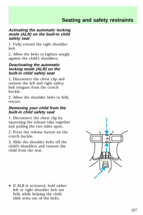
Activating the automatic lockingmode (ALR) on the built-in childsafety seat1. Fully extend the right shoulderbelt.
2. Allow the belts to tighten snuglyagainst the child’s shoulders.
Deactivating the automaticlocking mode (ALR) on thebuilt-in child safety seat1. Disconnect the chest clip andremove the left and right safetybelt tongues from the crotchbuckle.
2. Allow the shoulder belts to fullyretract.
Removing your child from thebuilt-in child safety seat1. Disconnect the chest clip bysqueezing the release tabs togetherand pulling the two sides apart.
2. Press the release button on thecrotch buckle.
3. Slide the shoulder belts off thechild’s shoulders and remove thechild from the seat.
• If ALR is activated, hold eitherleft or right shoulder belt outfully while helping the childslide arms out of the belts.
uno_canceling_alr_in_seat
uno_removing_child_from_seat
Seating and safety restraints
107
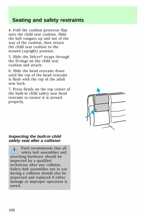
4. Fold the cushion protector flaponto the child seat cushion. Slidethe belt tongues up and out of theway of the cushion, then returnthe child seat cushion to thestowed (upright) position.
5. Slide the Velcrot straps throughthe D-rings on the child seatcushion and attach.
6. Slide the head restraint downuntil the top of the head restraintis flush with the top of the adultseat back.
7. Press firmly on the top center ofthe built-in child safety seat headrestraint to ensure it is stowedproperly.
Inspecting the built-in childsafety seat after a collision
Ford recommends that allsafety belt assemblies and
attaching hardware should beinspected by a qualifiedtechnician after any collision.Safety belt assemblies not in useduring a collision should also beinspected and replaced if eitherdamage or improper operation isnoted.
uno_inspecting_seat
Seating and safety restraints
108
All built-in child restraints,including seats, buckles,
retractors, seat latches,interlocks, and attachinghardware should be inspected bya qualified dealer technician afterany collision.
Seating and safety restraints
109
Important safety precautionsA computer system controls theengine’s idle revolutions perminute (RPM). When the enginestarts, the idle RPM runs faster towarm the engine. If the engine idlespeed does not slow downautomatically, have the vehiclechecked. Do not allow the vehicleto idle for more than ten minutes.
Extended idling at highengine speeds can produce
very high temperatures in theengine and exhaust system,creating the risk of fire or otherdamage.
Do not park, idle, or driveyour vehicle in dry grass
or other dry ground cover. Theemission system heats up theengine compartment and exhaustsystem, which can start a fire.
Do not start your vehiclein a closed garage or in
other enclosed areas. Exhaustfumes can be toxic. Always openthe garage door before you startthe engine. See Guardingagainst exhaust fumes in thischapter for more instructions.
com_important_precautions.05
Starting
110
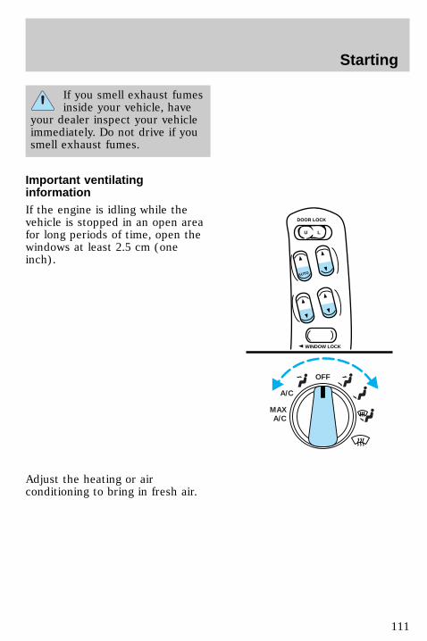
If you smell exhaust fumesinside your vehicle, have
your dealer inspect your vehicleimmediately. Do not drive if yousmell exhaust fumes.
Important ventilatinginformationIf the engine is idling while thevehicle is stopped in an open areafor long periods of time, open thewindows at least 2.5 cm (oneinch).
Adjust the heating or airconditioning to bring in fresh air.
OFF
A/C
MAXA/C
U L
DOOR LOCK
WINDOW LOCK
AUTO
uno_ventilation_info
Starting
111
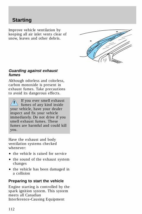
Improve vehicle ventilation bykeeping all air inlet vents clear ofsnow, leaves and other debris.
Guarding against exhaustfumesAlthough odorless and colorless,carbon monoxide is present inexhaust fumes. Take precautionsto avoid its dangerous effects.
If you ever smell exhaustfumes of any kind inside
your vehicle, have your dealerinspect and fix your vehicleimmediately. Do not drive if yousmell exhaust fumes. Thesefumes are harmful and could killyou.
Have the exhaust and bodyventilation systems checkedwhenever:
• the vehicle is raised for service
• the sound of the exhaust systemchanges
• the vehicle has been damaged ina collision
Preparing to start the vehicleEngine starting is controlled by thespark ignition system. This systemmeets all CanadianInterference-Causing Equipment
com_guarding_exhaust.01
uno_preparing_start
Starting
112
standard requirements regulatingthe impulse electrical field strengthof radio noise.
When starting a fuel-injectedengine, avoid pressing theaccelerator before or duringstarting. Only use the acceleratorwhen you have difficulty startingthe engine. For more informationon starting the vehicle, refer toStarting the vehicle in thischapter.
Before starting the vehicle:
1. Make sure all vehicle occupantshave buckled their safety belts. Formore information on safety beltsand their proper usage, refer tothe Seating and safety restraintschapter.
2. Make sure the headlamps andvehicle accessories are off. OFF
Starting
113
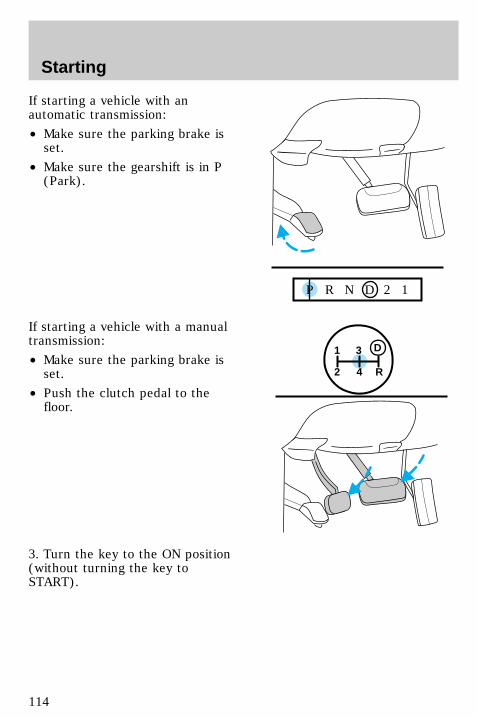
If starting a vehicle with anautomatic transmission:
• Make sure the parking brake isset.
• Make sure the gearshift is in P(Park).
If starting a vehicle with a manualtransmission:
• Make sure the parking brake isset.
• Push the clutch pedal to thefloor.
3. Turn the key to the ON position(without turning the key toSTART).
P R N D 2 1
1
2 4 R
3 D
Starting
114
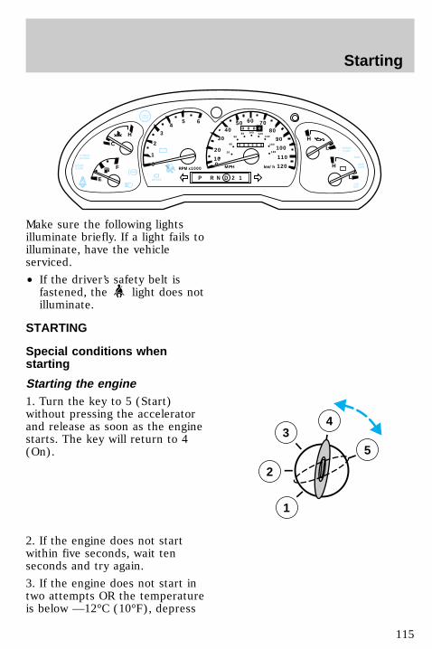
Make sure the following lightsilluminate briefly. If a light fails toilluminate, have the vehicleserviced.
• If the driver’s safety belt isfastened, the light does notilluminate.
STARTING
Special conditions whenstarting
Starting the engine1. Turn the key to 5 (Start)without pressing the acceleratorand release as soon as the enginestarts. The key will return to 4(On).
2. If the engine does not startwithin five seconds, wait tenseconds and try again.
3. If the engine does not start intwo attempts OR the temperatureis below —12°C (10°F), depress
0ABS
- +
P R N D 2 1
RPMx1000
1
2
34
5 6
- +
H
H
L
L
H
C
F
E!
BRAKE
CHECKGAGE
0
20
10
30
4050 60 70
80
90
110
120
0 0 0 0 0 0
o o o o
10020
40
6080 100 120
140
160
180
MPH km/hDOORAJAR
CHECKGAUGE
O/DOFF
4WDLOW
4WD
SPEEDCONT
3
2
1
5
4
uno_special_conditions_title
uno_starting_vehicle
Starting
115
accelerator and start the enginewhile holding the acceleratordown. Release accelerator whenengine starts.
4. After idling for a few seconds,apply the brake and release theparking brake.
Using the engine block heater(if equipped)An engine block heater warms theengine coolant, which improvesstarting, warms up the enginefaster and allows theheater-defroster system to respondquickly. They are stronglyrecommended if you live in aregion where temperatures reach—23°C (–10°F) or below.
For best results, plug the heater inat least three hours before startingthe vehicle. Using the heater forlonger than three hours will notharm the engine, so the heater canbe plugged in the night beforestarting the vehicle.
To prevent electricalshock, do not use your
heater with ungroundedelectrical systems ortwo-pronged (cheater) adapters.
com_engine_heater.01
Starting
116
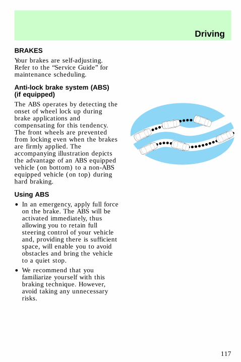
BRAKESYour brakes are self-adjusting.Refer to the “Service Guide” formaintenance scheduling.
Anti-lock brake system (ABS)(if equipped)The ABS operates by detecting theonset of wheel lock up duringbrake applications andcompensating for this tendency.The front wheels are preventedfrom locking even when the brakesare firmly applied. Theaccompanying illustration depictsthe advantage of an ABS equippedvehicle (on bottom) to a non-ABSequipped vehicle (on top) duringhard braking.
Using ABS• In an emergency, apply full forceon the brake. The ABS will beactivated immediately, thusallowing you to retain fullsteering control of your vehicleand, providing there is sufficientspace, will enable you to avoidobstacles and bring the vehicleto a quiet stop.
• We recommend that youfamiliarize yourself with thisbraking technique. However,avoid taking any unnecessaryrisks.
com_brakes.01
com_abs.01
com_using_abs.01
uno_parking_brake
Driving
117
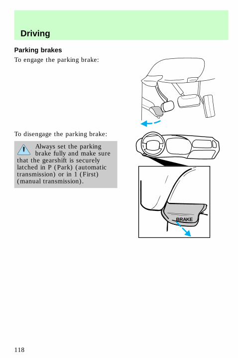
Parking brakesTo engage the parking brake:
To disengage the parking brake:
Always set the parkingbrake fully and make sure
that the gearshift is securelylatched in P (Park) (automatictransmission) or in 1 (First)(manual transmission).
BRAKE
com_traction-lok.01
Driving
118
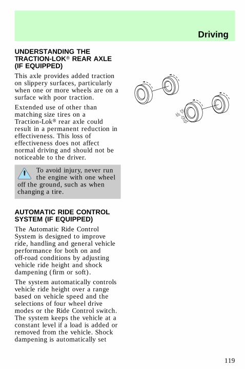
UNDERSTANDING THETRACTION-LOKT REAR AXLE(IF EQUIPPED)This axle provides added tractionon slippery surfaces, particularlywhen one or more wheels are on asurface with poor traction.
Extended use of other thanmatching size tires on aTraction-Lokt rear axle couldresult in a permanent reduction ineffectiveness. This loss ofeffectiveness does not affectnormal driving and should not benoticeable to the driver.
To avoid injury, never runthe engine with one wheel
off the ground, such as whenchanging a tire.
AUTOMATIC RIDE CONTROLSYSTEM (IF EQUIPPED)The Automatic Ride ControlSystem is designed to improveride, handling and general vehicleperformance for both on andoff-road conditions by adjustingvehicle ride height and shockdampening (firm or soft).
The system automatically controlsvehicle ride height over a rangebased on vehicle speed and theselections of four wheel drivemodes or the Ride Control switch.The system keeps the vehicle at aconstant level if a load is added orremoved from the vehicle. Shockdampening is automatically set
uno_automatic_ride
Driving
119

based on driver and road inputs tooptimize ride. The combination offirm dampening and height changealso provides maximum suspensionfeedback for improved off-roadsafety and performance.
The vehicle will drop to its lowestposition when the ignition isturned to the Off position toprovide easy entry and exit to ofthe vehicle. As a safetyconsideration, whenever a door isopened (including the liftgate andliftgate glass), the systemmemorizes and maintains theheight at the moment the door wasopened. The system will maintainthis height either until all doorsare closed or until vehicle speedexceeds 16 kph (10 mph).
An on board air compressor andsolenoids are used to raise andlower the vehicle. It is normal tooccasionally a buzz or clickingfrom the vehicle even when theignition is turned to Off. Thesystem stays energized for 40minutes after the ignition is turnedoff to compensate for any loadchanges after the vehicle is parked.
The Automatic Ride Controlsystem operation can be monitoredthrough the message center. Referto Message center in theInstrumentation chapter.
uno_ride_cont_switch
Driving
120
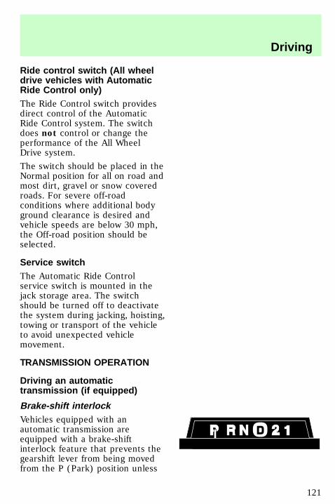
Ride control switch (All wheeldrive vehicles with AutomaticRide Control only)The Ride Control switch providesdirect control of the AutomaticRide Control system. The switchdoes not control or change theperformance of the All WheelDrive system.
The switch should be placed in theNormal position for all on road andmost dirt, gravel or snow coveredroads. For severe off-roadconditions where additional bodyground clearance is desired andvehicle speeds are below 30 mph,the Off-road position should beselected.
Service switchThe Automatic Ride Controlservice switch is mounted in thejack storage area. The switchshould be turned off to deactivatethe system during jacking, hoisting,towing or transport of the vehicleto avoid unexpected vehiclemovement.
TRANSMISSION OPERATION
Driving an automatictransmission (if equipped)
Brake-shift interlockVehicles equipped with anautomatic transmission areequipped with a brake-shiftinterlock feature that prevents thegearshift lever from being movedfrom the P (Park) position unless
uno_service_switch
uno_transmission_title
uno_driving_an_automatic
uno_brake_shift_interlock
Driving
121
the brake pedal is depressed. Ifyou cannot move the gearshiftlever from P (Park) with the brakepedal depressed:
1. Apply the parking brake.
2. Turn the ignition key to Lock,then remove the key.
3. Insert the key and turn theignition off.
4. Apply the brake pedal and shiftinto N (Neutral).
5. Start the vehicle.
If it is necessary to use thisprocedure to move the gearshiftlever , it is possible that a fusemay have blown and the vehicle’sbrakelamps may not be working.Refer to Fuses and relays in theRoadside emergencies chapter.
Driving (4R70Wtransmission-5.0L engines only)
D Overdrive The normal drivingposition for the best fuel economy.Transmission operates in gears onethrough four.
D can be deactivated by pressingthe switch selector lever. TheO/DOFF light will illuminate.
D Drive Not shown on the display.Activate by pressing thetransmission control switch.O/DOFF will illuminate in theinstrument cluster. Transmissionoperates in gears one throughthree. D (Drive) provides moreengine braking than
D (Overdrive) and is useful when
uno_4r70w
Driving
122
towing a trailer or heavy loadsthrough heavy terrain.
To return to D (Overdrive)mode, press the transmissioncontrol switch. O/D
OFF will remain off.
When starting your vehicle, thetransmission will automaticallyreturn to normal D (Overdrive)mode.
2 Second Use the 2 (Second)position to start-up on slipperyroads or to provide additionalbraking on downgrades.Transmission operates in gears oneand two.
1 Low Use the 1 (Low) position toprovide maximum engine brakingon steep downgrades. Upshifts maybe made by shifting to the 2(Second) position or to
D (Overdrive). Selecting the 1(Low) position at higher speedscauses the transmission todownshift through the gears andwill shift to 1 (Low) after thevehicle decelerates to the properspeed.
Driving (5R55Etransmission-4.0L engines only)
D Overdrive The normal drivingposition for the best fuel economy.Transmission operates in gears onethrough five.
D can be deactivated by pressingthe transmission control switch onthe selector lever. The O/D
OFF willilluminate.
uno_5r55e
Driving
123

D Drive Not shown on the display.Activate by pressing thetransmission control switch.O/DOFF will illuminate in theinstrument cluster. Transmissionoperates in gears one through four.D (Drive) provides more enginebraking than D (Overdrive) andis useful when towing a trailer orheavy loads through heavy terrain.
To return to D (Overdrive)mode, press the transmissioncontrol switch. O/D
OFF will turn off.
When starting your vehicle, thetransmission will automaticallyreturn to normal D (Overdrive)mode.
2 Second Use the 2 (Second)position to start-up on slipperyroads or to provide additionalbraking on downgrades.Transmission operates in thirdgear.
1 Low Use the 1 (Low) position toprovide maximum engine brakingon steep downgrades. Upshifts maybe made by shifting to the 2(Second) position or to
D (Overdrive). Selecting the 1(Low) position at high speedscauses the transmission todownshift through the gears andwill shift to 1 (Low) after thevehicle decelerates to the properspeed.
uno_driving_manual_trans
Driving
124
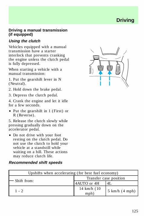
Driving a manual transmission(if equipped)
Using the clutchVehicles equipped with a manualtransmission have a starterinterlock that prevents crankingthe engine unless the clutch pedalis fully depressed.
When starting a vehicle with amanual transmission:
1. Put the gearshift lever in N(Neutral).
2. Hold down the brake pedal.
3. Depress the clutch pedal.
4. Crank the engine and let it idlefor a few seconds.
• Put the gearshift in 1 (First) orR (Reverse).
5. Release the clutch slowly whilepressing gradually down on theaccelerator pedal.
• Do not drive with your footresting on the clutch pedal. Donot use the clutch to hold yourvehicle at a standstill whilewaiting on a hill. These actionsmay reduce clutch life.
Recommended shift speeds
Upshifts when accelerating (for best fuel economy)
Shift from:Transfer case position
4AUTO or 4H 4L
1 - 214 km/h (10
mph)5 km/h (4 mph)
uno_using_clutch
uno_shift_speeds
Driving
125
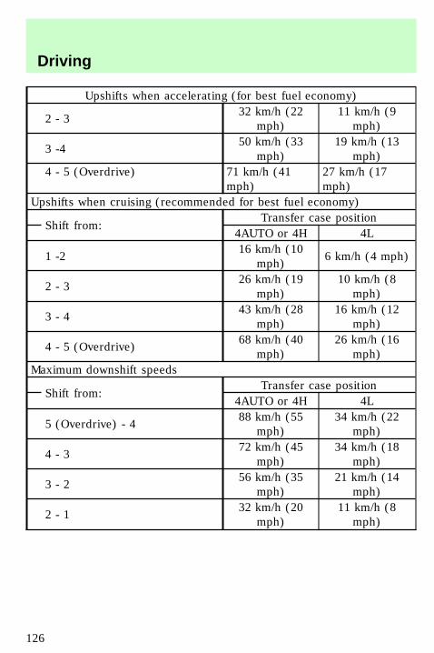
Upshifts when accelerating (for best fuel economy)
2 - 332 km/h (22
mph)11 km/h (9
mph)
3 -450 km/h (33
mph)19 km/h (13
mph)4 - 5 (Overdrive) 71 km/h (41
mph)27 km/h (17mph)
Upshifts when cruising (recommended for best fuel economy)
Shift from:Transfer case position
4AUTO or 4H 4L
1 -216 km/h (10
mph)6 km/h (4 mph)
2 - 326 km/h (19
mph)10 km/h (8
mph)
3 - 443 km/h (28
mph)16 km/h (12
mph)
4 - 5 (Overdrive)68 km/h (40
mph)26 km/h (16
mph)Maximum downshift speeds
Shift from:Transfer case position
4AUTO or 4H 4L
5 (Overdrive) - 488 km/h (55
mph)34 km/h (22
mph)
4 - 372 km/h (45
mph)34 km/h (18
mph)
3 - 256 km/h (35
mph)21 km/h (14
mph)
2 - 132 km/h (20
mph)11 km/h (8
mph)
Driving
126
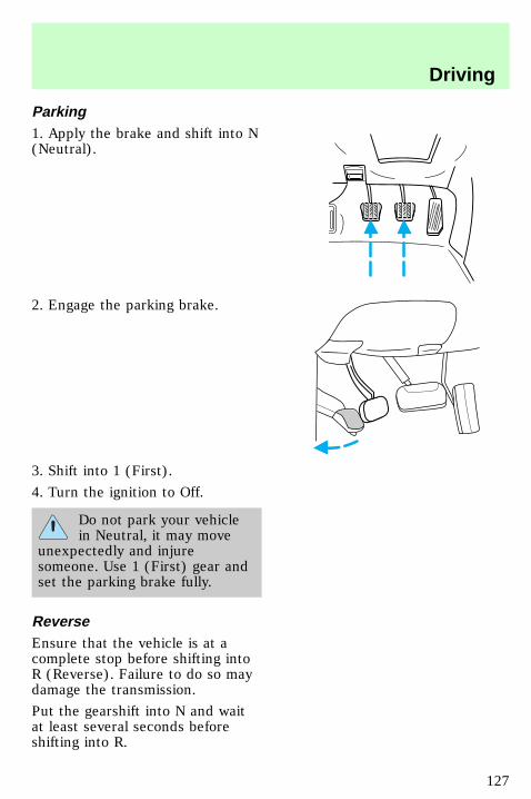
Parking1. Apply the brake and shift into N(Neutral).
2. Engage the parking brake.
3. Shift into 1 (First).
4. Turn the ignition to Off.
Do not park your vehiclein Neutral, it may move
unexpectedly and injuresomeone. Use 1 (First) gear andset the parking brake fully.
ReverseEnsure that the vehicle is at acomplete stop before shifting intoR (Reverse). Failure to do so maydamage the transmission.
Put the gearshift into N and waitat least several seconds beforeshifting into R.
uno_parking
uno_reverse
Driving
127
You can shift into R (Reverse) onlyby moving the gearshift from leftof 3 (Third) and 4 (Fourth) gearsbefore you shift into R (Reverse).This is s special lockout featurethat protects you from accidentlyshifting into R (Reverse) when youdownshift from 5 (Overdrive).
USING THE CONTROL TRAC4WD SYSTEM (IF EQUIPPED)
Positions of the Control Tracsystem4WD AUTO — Full powerdelivered to front and rear axlesfor increased traction. Use thismode for normal on-road operatingconditions such as dry roadsurfaces, wet pavement, snow andgravel.
4WD HIGH — 4WD with fullpower to the rear axle and highercontinuous power level to the frontaxle than 4WD AUTO. Use thismode for severe winter or off-roadconditions such as deep snow, ice,shallow sand.
4WD LOW — Full power to bothaxles, including a lower gear ratiofor low-speed. Use this mode foroff-raod applications that requireextra power such as deep sand,steep grades and pulling a boat outof the water. 4WD LOW operationis not recommended on drypavement.
uno_four-wd_title
uno_positions_control_trac
uno_using_control_trac_title
Driving
128
Using the Control Trac system
Shifting between 4WD AUTOand 4WD HIGHEither shift can be done at a stop,or at any forward speed.
• The 4WD HIGH light willilluminate when you switch thecontrol to 4WD HIGH or turn offif you switch to 4WD AUTO.
Shifting from 4WD AUTO or4WD HIGH to 4WD LOWTo perform this shift, complete thefollowing steps:
1. Stop the vehicle and depress thebrake.
2. Place the automatictransmission in N (Neutral) ordepress the manual transmissionclutch.
3. Rotate the 4WD control to 4WDLOW.
Shifting from 4WD LOW to 4WDAUTO or 4WD HIGHTo perform this shift, complete thefollowing steps:
1. Bring the vehicle to a stop.
2. Depress and hold the brake.
3. Place the automatictransmission gearshift lever in N(Neutral) or depress the manualtransmission clutch.
4. Move the 4WD control to the4WD AUTO or 4WD HIGH position.
uno_2h_to_4h
uno_4h_to_2h
uno_4h_to_4l
uno_driving_off_road
Driving
129

Driving off-road with 4WDYour vehicle is specially equippedfor driving on snow, sand, mud orother rough terrain and hasoperating characteristics that differfrom those of other conventionalvehicles.
When using 4WD, maintainsteering wheel control at all times,especially in rough terrain. Sincesudden changes in terrain canresult in abrupt steering motion,always grip the steering wheelfrom the outside. Do not grip thespokes.
Drive cautiously to avoid vehicledamage from road debris such asrocks or stumps. Be sure to mapout your route before driving inany off road area.
For more information on drivingoff-road and proper operation ofyour 4WD vehicle, refer the “FourWheeling” supplement in yourOwners Portfolio.
Driving over sandWhen driving over sand, try tokeep all four wheels on the mostsolid area of the trail. Do notreduce the tire pressures but shiftto a lower gear and drive steadilythrough the terrain. Apply the
uno_driving_sand
Driving
130
accelerator slowly and avoidspinning the wheels.
Driving through mud and waterAfter driving through mud, cleanoff residue stuck to rotatingdriveshafts and tires. Excess mudstuck on tires and rotatingdriveshafts causes an imbalancethat could damage drivecomponents.
If you must drive through highwater, drive slowly. Traction orbrake capability may be limited.
When driving through water,determine the depth; avoid waterhigher than the bottom of the hubs(if possible) and proceed slowly. Ifthe ignition system gets wet, thevehicle may stall.
Once through water, always try thebrakes. Wet brakes do not stop thevehicle as effectively as dry brakes.Drying can be improved by movingyour vehicle slowly while applyinglight pressure on the brake pedal.
If the transmission and transfercase are submerged in water, theirfluids should be checked andchanged, if necessary.
If the rear axle is submerged inwater, the rear axle lubricantshould be checked and changed, ifnecessary. The rear axle is filledwith a synthetic lubricant and doesnot normally require a lubricantchange for the life of the vehicle.Rear axle lubricant quantitiesshould not need to be checkedunless a leak is suspected.
uno_driving_mud_water
uno_driving_hill
Driving
131
Driving Through WaterDo not drive quickly throughstanding water, especially if thedepth is unknown. Traction orbrake capability may be limitedand if the ignition system gets wet,your engine may stall. Water mayalso enter your engine’s air intakeand severely damage your engine.
If driving through deep or standingwater is unavoidable, proceed veryslowly. Never drive through waterthat is higher than the bottom ofthe hubs (truck) / wheel rims(car).
Once through the water, always trythe brakes. Wet brakes do not stopthe vehicle as effectively as drybrakes. Drying can be improved bymoving your vehicle slowly whileapplying light pressure on thebrake pedal.
Driving on hill or slope terrainWhen driving on a hill, avoiddriving crosswise or turning onsteep slopes. You could losetraction and slip sideways. Drivestraight up, straight down or avoidthe hill completely. Know theconditions on the other side of ahill before driving over the crest.
When climbing a steep hill, start ina lower gear rather thandownshifting to a lower gear froma higher gear once the ascent hasstarted. This reduces strain on theengine and the possibility ofstalling.
Driving
132
When descending a steep hill,avoid sudden braking. Rapidpumping of the brake pedal willhelp slow the vehicle and stillmaintain steering control.
When speed control is on and youare driving uphill, your vehiclespeed may drop considerably,especially if you are carrying aheavy load.
If vehicle speed drops more than15–25 km/h (8–14 mph), the speedcontrol will cancel automatically.Resume speed with acceleratorpedal.
If speed control cancels afterclimbing the hill, reset speed bypressing and holding the SETACCEL button (to resume speedsover 50 km/h (30 mph).
Automatic transmission may shiftfrequently while driving up steepgrades. Eliminate frequent shiftingby shifting out of D (Overdrive)into D (Drive).
Driving on snow and iceAvoid sudden applications ofpower and quick changes ofdirection on snow and ice. Applythe accelerator slowly and steadilywhen starting from a full stop.
When braking, apply the brakes asyou normally would. In order toallow the anti-lock brake system(ABS) to operate properly, keepsteady pressure on the brakepedal.
uno_driving_snow_ice
Driving
133
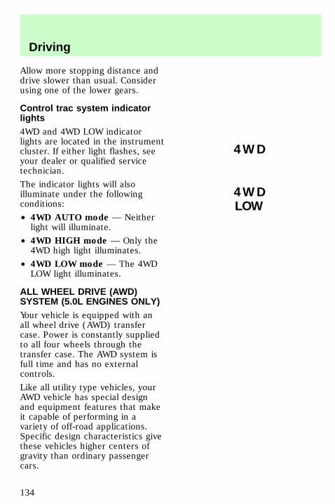
Allow more stopping distance anddrive slower than usual. Considerusing one of the lower gears.
Control trac system indicatorlights4WD and 4WD LOW indicatorlights are located in the instrumentcluster. If either light flashes, seeyour dealer or qualified servicetechnician.
The indicator lights will alsoilluminate under the followingconditions:
• 4WD AUTO mode — Neitherlight will illuminate.
• 4WD HIGH mode — Only the4WD high light illuminates.
• 4WD LOW mode — The 4WDLOW light illuminates.
ALL WHEEL DRIVE (AWD)SYSTEM (5.0L ENGINES ONLY)Your vehicle is equipped with anall wheel drive (AWD) transfercase. Power is constantly suppliedto all four wheels through thetransfer case. The AWD system isfull time and has no externalcontrols.
Like all utility type vehicles, yourAWD vehicle has special designand equipment features that makeit capable of performing in avariety of off-road applications.Specific design characteristics givethese vehicles higher centers ofgravity than ordinary passengercars.
4WD
4WDLOW
uno_indicator_lights
uno_awd
Driving
134
Utility and four-wheeldrive vehicles are NOT
designed for cornering at speedsas high as passenger cars anymore than low-slung sports carsare designed to performsatisfactorily under off-roadconditions. Avoid sharp turns orabrupt maneuvers in thesevehicles.
LOADING YOUR VEHICLEBefore loading your vehicle,familiarize yourself with theseterms:
• Base curb weight —Weight ofthe vehicle including anystandard equipment, fluids,lubricants, etc. It does notinclude passengers oraftermarket equipment.
• Payload — Combinedmaximum allowable weight ofpassengers, cargo and optionalequipment.
• GVW (Gross Vehicle Weight)— Base curb weight plus thepayload weight. The GVW is nota limit or a specification.
• GVWR (Gross Vehicle WeightRating) — Maximum totalweight of the base vehicle,passengers, optional equipmentand cargo. The GVWR is specificto each vehicle and is listed onthe Safety ComplianceCertification Label on thedriver’s door pillar.
uno_heavy_load
Driving
135
• GAWR (Gross Axle WeightRating) — Carrying capacityfor each axle system (front andrear). The GAWR is specific toeach vehicle and is listed on theSafety Compliance CertificationLabel on the driver door pillar.
• GCW (Gross CombinedWeight) — The GCW is themaximum combined weight ofthe towing vehicle (includingpassengers and cargo) and theloaded trailer. The GCW isspecified by the manufacturer toindicate the combined maximumloaded weight that the vehicle isdesigned to tow.
Payload = GVWR minus Basecurb weight
To obtain the correct weights foryour vehicle, try taking yourvehicle to a shipping company oran inspection station for trucks.
Do not use replacement tires withlower weight capacities than theoriginals because they might lowerthe vehicle’s GVWR and GAWR.(Replacement tires with a higherweight limit than the originals donot increase the GVWR or theGAWR limitations.)
In high altitudes, engines will losepower at a rate of 3% power per300 m (1000 ft) increase inelevation. A reduction in GVW andGCW is recommended formaximum vehicle performance.
Driving
136
Do not exceed the GVWRor the GAWR specified on
the Safety ComplianceCertification Label.
It is extremely dangerousto ride in a cargo area,
inside or outside of a vehicle. Ina collision, people riding in theseareas are more likely to beseriously injured or killed. Do notallow people to ride in any areaof your vehicle that is notequipped with seats and safetybelts. Be sure everyone in yourvehicle is in a seat and using asafety belt properly.
Driving with a heavy loadThe total vehicle weight plus thetotal weight of passengers andcargo should never exceed theGVWR.
The weight that the vehicle carriesover the front and rear axlesshould never exceed the GVWR forthe respective axle.
The weight limits of your vehicle’stires affect the GVWR or GAWRlimitations. Using tires with higherweight limits than the original tireswill not increase the GVWR orGAWR of your vehicle; using tireswith lower weight limits may lowerthe GVWR or GAWR of yourvehicle.
uno_driving_heavy_load
uno_trailer_title
Driving
137
TRAILER TOWINGTrailer towing with your vehiclemay require the use of a trailertow option package.
Trailer towing puts additional loadson your vehicle’s engine,transmission, axle, brakes, tires,and suspension. For your safetyand to maximize vehicleperformance, be sure to use theproper equipment while towing.
Follow these guidelines to ensuresafe towing procedure:
• Stay within your vehicle’s loadlimits.
• Thoroughly prepare your vehiclefor towing. Refer to Preparingto tow in this chapter.
• Use extra caution when drivingwhile trailer towing. Refer toDriving while towing in thischapter.
• Service your vehicle morefrequently if you tow a trailer.Refer to the severe dutyschedule in the “Service Guide”.
• Do not tow a trailer until yourvehicle has been driven at least800 km (500 miles).
• Refer to the instructionsincluded with towing accessoriesfor the proper installation andadjustment specifications.
• Speed control may shut off ifyou are towing on long, steepgrades.
Driving
138
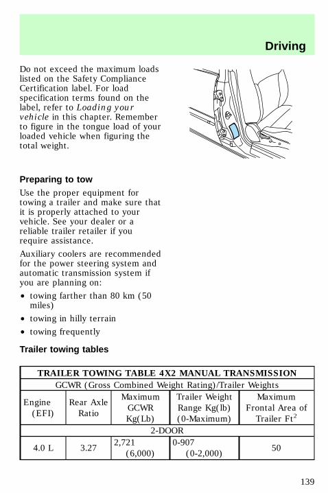
Do not exceed the maximum loadslisted on the Safety ComplianceCertification label. For loadspecification terms found on thelabel, refer to Loading yourvehicle in this chapter. Rememberto figure in the tongue load of yourloaded vehicle when figuring thetotal weight.
Preparing to towUse the proper equipment fortowing a trailer and make sure thatit is properly attached to yourvehicle. See your dealer or areliable trailer retailer if yourequire assistance.
Auxiliary coolers are recommendedfor the power steering system andautomatic transmission system ifyou are planning on:
• towing farther than 80 km (50miles)
• towing in hilly terrain
• towing frequently
Trailer towing tables
TRAILER TOWING TABLE 4X2 MANUAL TRANSMISSION
GCWR (Gross Combined Weight Rating)/Trailer Weights
Engine(EFI)
Rear AxleRatio
MaximumGCWRKg(Lb)
Trailer WeightRange Kg(lb)(0-Maximum)
MaximumFrontal Area ofTrailer Ft2
2-DOOR
4.0 L 3.272,721
(6,000)0-907
(0-2,000)50
uno_preparing_to_tow_title
uno_tables_towing
Driving
139
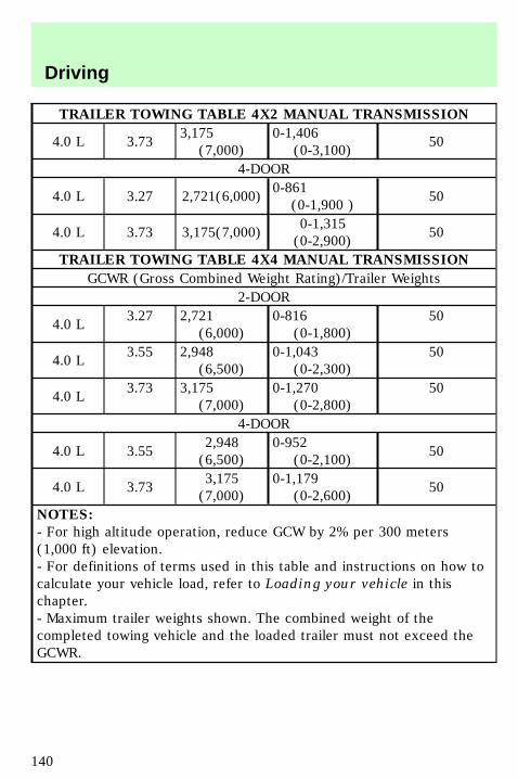
TRAILER TOWING TABLE 4X2 MANUAL TRANSMISSION
4.0 L 3.733,175
(7,000)0-1,406
(0-3,100)50
4-DOOR
4.0 L 3.27 2,721(6,000)0-861
(0-1,900 )50
4.0 L 3.73 3,175(7,000)0-1,315(0-2,900)
50
TRAILER TOWING TABLE 4X4 MANUAL TRANSMISSION
GCWR (Gross Combined Weight Rating)/Trailer Weights2-DOOR
4.0 L3.27 2,721
(6,000)0-816
(0-1,800)50
4.0 L3.55 2,948
(6,500)0-1,043
(0-2,300)50
4.0 L3.73 3,175
(7,000)0-1,270
(0-2,800)50
4-DOOR
4.0 L 3.552,948(6,500)
0-952(0-2,100)
50
4.0 L 3.733,175(7,000)
0-1,179(0-2,600)
50
NOTES:
- For high altitude operation, reduce GCW by 2% per 300 meters(1,000 ft) elevation.- For definitions of terms used in this table and instructions on how tocalculate your vehicle load, refer to Loading your vehicle in thischapter.- Maximum trailer weights shown. The combined weight of thecompleted towing vehicle and the loaded trailer must not exceed theGCWR.
Driving
140
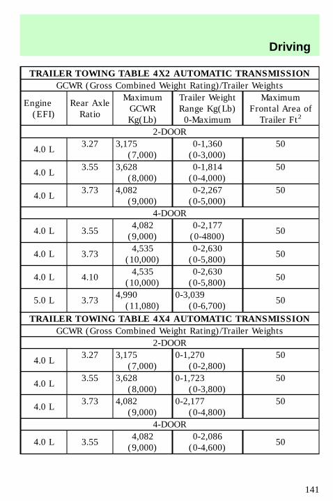
TRAILER TOWING TABLE 4X2 AUTOMATIC TRANSMISSION
GCWR (Gross Combined Weight Rating)/Trailer Weights
Engine(EFI)
Rear AxleRatio
MaximumGCWRKg(Lb)
Trailer WeightRange Kg(Lb)0-Maximum
MaximumFrontal Area ofTrailer Ft2
2-DOOR
4.0 L3.27 3,175
(7,000)0-1,360(0-3,000)
50
4.0 L3.55 3,628
(8,000)0-1,814(0-4,000)
50
4.0 L3.73 4,082
(9,000)0-2,267(0-5,000)
50
4-DOOR
4.0 L 3.554,082(9,000)
0-2,177(0-4800)
50
4.0 L 3.734,535
(10,000)0-2,630(0-5,800)
50
4.0 L 4.104,535
(10,000)0-2,630(0-5,800)
50
5.0 L 3.734,990(11,080)
0-3,039(0-6,700)
50
TRAILER TOWING TABLE 4X4 AUTOMATIC TRANSMISSION
GCWR (Gross Combined Weight Rating)/Trailer Weights2-DOOR
4.0 L3.27 3,175
(7,000)0-1,270
(0-2,800)50
4.0 L3.55 3,628
(8,000)0-1,723
(0-3,800)50
4.0 L3.73 4,082
(9,000)0-2,177
(0-4,800)50
4-DOOR
4.0 L 3.554,082(9,000)
0-2,086(0-4,600)
50
Driving
141
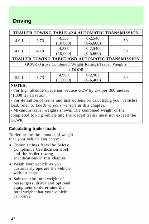
TRAILER TOWING TABLE 4X4 AUTOMATIC TRANSMISSION
4.0 L 3.734,535
(10,000)0-2,540(0-5,600)
50
4.0 L 4.104,535
(10,000)0-2,540(0-5,600)
50
TRAILER TOWING TABLE AWD AUTOMATIC TRANSMISSION
GCWR (Gross Combined Weight Rating)/Trailer Weights4-DOOR
5.0 L 3.734,990
(11,000)0-2,902(0-6,400)
50
NOTES:
- For high altitude operation, reduce GCW by 2% per 300 meters(1,000 ft) elevation.- For definition of terms and instructions on calculating your vehicle’sload, refer to Loading your vehicle in this chapter.- Maximum trailer weights shown. The combined weight of thecompleted towing vehicle and the loaded trailer must not exceed theGCWR.
Calculating trailer loadsTo determine the amount of weightthat your vehicle can carry:
• Obtain ratings from the SafetyCompliance Certification labeland the trailer towingspecifications in this chapter.
• Weigh your vehicle as youcustomarily operate the vehiclewithout cargo.
• Subtract the total weight ofpassengers, driver and optionalequipment to determine thetotal weight that your vehiclecan carry.
uno_calculating_towing
Driving
142
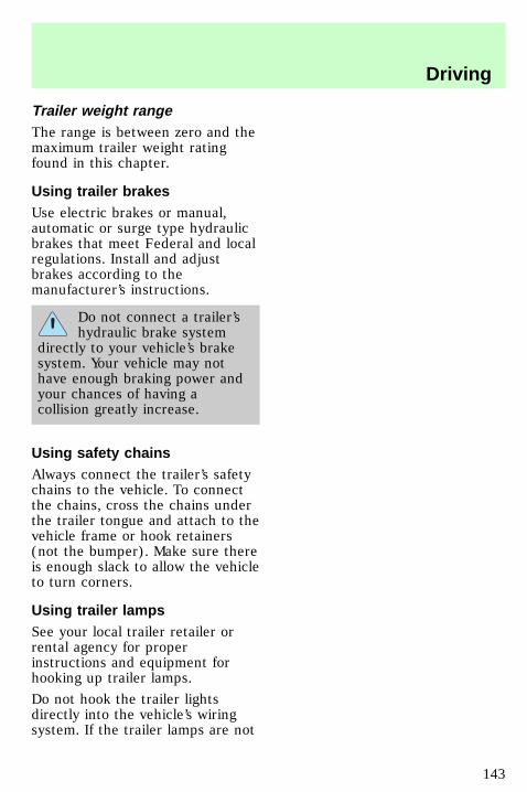
Trailer weight rangeThe range is between zero and themaximum trailer weight ratingfound in this chapter.
Using trailer brakesUse electric brakes or manual,automatic or surge type hydraulicbrakes that meet Federal and localregulations. Install and adjustbrakes according to themanufacturer’s instructions.
Do not connect a trailer’shydraulic brake system
directly to your vehicle’s brakesystem. Your vehicle may nothave enough braking power andyour chances of having acollision greatly increase.
Using safety chainsAlways connect the trailer’s safetychains to the vehicle. To connectthe chains, cross the chains underthe trailer tongue and attach to thevehicle frame or hook retainers(not the bumper). Make sure thereis enough slack to allow the vehicleto turn corners.
Using trailer lampsSee your local trailer retailer orrental agency for properinstructions and equipment forhooking up trailer lamps.
Do not hook the trailer lightsdirectly into the vehicle’s wiringsystem. If the trailer lamps are not
uno_brakes_trailer
uno_safety_chains
uno_lamps_trailer
Driving
143
working properly, the warninglights in the instrument clustermay not work properly.
Using a hitchDo not use hitches that:
• clamp onto the vehicle bumper
• attach to the axle.
Distribute the load so that only 10to 15% of the total weight of thetrailer is on the tongue. tie downthe load so that it does not shiftand change the weight on thehitch. Follow the towinginstructions of a reputable rentalagency.
Driving while towing a trailerDo not drive faster than 70 km/h(45 mph) while towing a 454 kg(1000 lb) trailer. Do not drivefaster than 72 km/h (45 mph) withany weight trailer while towing inhilly terrain or on hot days.
Speed control (if equipped) maynot work properly while towing onlong, steep grades.
If driving with an automatictransmission:
• use D or L rather than whiletowing up or down steep hills
• anticipate stops and brakegradually.
Towing behind another vehicleDo not tow your vehicle behindanother vehicle, such as an RV,unless front wheel dollies are used.
uno_hitch
uno_driving_towing
uno_towing_behind
Driving
144
Your vehicle can not be flat towedwith all wheels on the ground.
Servicing while towingIf you tow a trailer for longdistances, your vehicle requiresmore frequent service than avehicle not used for towing. Referto the “Service Guide” for moreinformation on maintenanceintervals.
Using a step bumperThe rear bumper is equipped withan integral hitch and requires onlya ball with a ¾ inch shankdiameter. The bumper has a ClassII capability (1590 kg / 3500 lbtrailer weight and 159 kg / 350 lbtongue weight).
Use a frame mounted weightdistributing hitch for trailers over1590 kg (3500 lb).
Launching or retrieving a boatWhen backing down a ramp duringboat launching or retrieval,
• Do not allow the static waterlevel to rise above the bottomedge of the rear bumper and
• Do not allow waves to breakhigher than 15 cm (six inches)above the bottom edge of therear bumper.
Exceeding these limits may allowwater to enter critical vehiclecomponents, adversely affectingdriveability, emissions andreliability.
uno_servicing_while_towing
uno_step_bumper_towing
com_launch-retrieving_boat.01
uno_roof-rack_title
Driving
145
USING THE LUGGAGE RACK(IF EQUIPPED)Maximum load is 100 lbs, evenlydistributed. If it is not possible todistribute the load, position it asfar rearward as possible.Adjustable tie down loops must beused to secure the load.
To adjust cross-bar position:
1. Loosen the thumbwheel at bothends of the cross-bar (bothcross-bars are adjustable).
2. Slide cross-bar to the desiredlocation.
3. Tighten thumbwheel at bothends of the cross-bar.
FUEL CONSUMPTIONFuel economy can be improved byavoiding:
• lack of regular, scheduledmaintenance
• excessive speed
• rapid acceleration
com_fuel_consumption.01
Driving
146
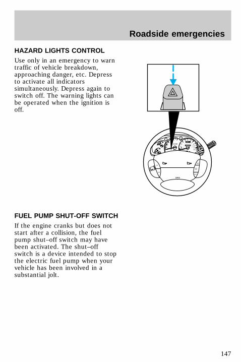
HAZARD LIGHTS CONTROLUse only in an emergency to warntraffic of vehicle breakdown,approaching danger, etc. Depressto activate all indicatorssimultaneously. Depress again toswitch off. The warning lights canbe operated when the ignition isoff.
FUEL PUMP SHUT-OFF SWITCHIf the engine cranks but does notstart after a collision, the fuelpump shut–off switch may havebeen activated. The shut–offswitch is a device intended to stopthe electric fuel pump when yourvehicle has been involved in asubstantial jolt.
0
P R N D 2 1
UNLEADEDFUEL ONLY
RPMx1000
1
2
34
5 6
H
C
F
E
RSM
SETACC
COAST
OFF
ON
SRS
- +
H
H
L
L
0
20
10
30
4050 60 70
80
90
110
120
0 0 0 0 0 0
o o o o
km/h
10020
40
6080 100 120
140
160
180
uno_hazard_switch
uno_fuel_shut-off
Roadside emergencies
147
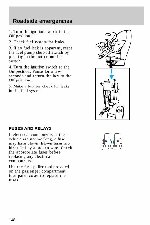
1. Turn the ignition switch to theOff position.
2. Check fuel system for leaks.
3. If no fuel leak is apparent, resetthe fuel pump shut-off switch bypushing in the button on theswitch.
4. Turn the ignition switch to theOn position. Pause for a fewseconds and return the key to theOff position.
5. Make a further check for leaksin the fuel system.
FUSES AND RELAYSIf electrical components in thevehicle are not working, a fusemay have blown. Blown fuses areidentified by a broken wire. Checkthe appropriate fuses beforereplacing any electricalcomponents.
Use the fuse puller tool providedon the passenger compartmentfuse panel cover to replace thefuses.
15
uno_fuses_relays_title
Roadside emergencies
148
Always replace a fuse withone that has the specified
amperage rating. Using a fusewith a higher amperage ratingcan cause severe wire damageand could start a fire.
Even after a fuse is replaced, itwill continue to blow if the causeof the overload is not identifiedand corrected. If the fusecontinues to blow, have thevehicle’s electrical system checkedby a qualified service technician.
To reset a circuit breaker, pressthe reset button.
Fuses
Standard fuse amperage ratingsand colors
Fuse rating Color
7.5 amp Brown10 amp Red15 amp Blue20 amp Yellow30 amp Light green30 amp fuse link Pink40 amp Green60 amp fuse link Yellow80 amp fuse link Black100 amp fuse link Blue
uno_fuses_title
uno_color_chart
Roadside emergencies
149
Passenger compartment fusepanelPull the panel out to access thepassenger compartment fuse panel.
Use the fuse puller tool providedon the fuse panel cover to replacefuses.
1 2 3 4
5 6 7 8
9 10 11 12
13 14 15 16
17 18 19 20
21 22 23 24
25 26
29 30
35
36
31 32
33 34
27 28
uno_passenger_comp_fuses
Roadside emergencies
150
Number Fuse Amperage
RatingCircuits Protected
1 7.5 amp Power mirror, powerantenna
2 7.5 amp High-mount brakelamp3 15 amp Parking lamp,
instrument clustergauges
4 10 amp Left headlamp, lampout warning
5 10 amp OBD system6 7.5 amp Air bag system, blower
relay, EATC7 7.5 amp Illumination switches8 10 amp Right headlamp, fog
lamp system, DRL,lamp out warning
9 10 amp EATC system, seatmemory, messagecenter, cellular phone,autolamps
10 7.5 amp EATC system, rearblower, speed control,GEM system, brakeinterlock, overheadconsole, automaticride control, lamp outwarning
11 7.5 amp Warning lamps,autolamp
12 10 amp Front washer, rearwasher & wiper
Roadside emergencies
151
Number Fuse Amperage
RatingCircuits Protected
13 15 amp PCM system,stoplamps, AWD,anti-lock brake, speedcontrol, trailer tow
14 10 amp Anti-lock system15 7.5 amp Air bag system,
instrument cluster16 30 amp Wiper run relay17 25 amp Cigar lighter18 15 amp A/C system19 25 amp Ignition coil, PCM
system20 7.5 amp Radio, power antenna,
GEM system,anti-theft, cellularphone
21 15 amp Turn/hazard flasher22 10 amp Turn signals23 10 amp Rear wiper system24 10 amp Starter relay25 7.5 amp Speedometer, GEM
system26 10 amp 5R55E/4R7OW
overdrive, DRLsystem, backup lamps,AWD, rear defroster
27 10 amp Under hood lamp, maplamps, glove box lamp,dome lamp, visorlamps, accessorydelay, dimmer switchillumination, 4x4system
Roadside emergencies
152
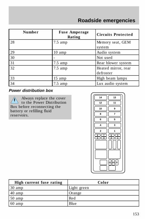
Number Fuse Amperage
RatingCircuits Protected
28 7.5 amp Memory seat, GEMsystem
29 10 amp Audio system30 - Not used31 7.5 amp Rear blower system32 7.5 amp Heated mirror, rear
defroster33 15 amp High beam lamps34 7.5 amp Lux audio system
Power distribution box
Always replace the coverto the Power Distribution
Box before reconnecting thebattery or refilling fluidreservoirs.
High current fuse rating Color
30 amp Light green40 amp Orange50 amp Red60 amp Blue
14 13
12 11
10 9
8 7
6 5
4 3
2
84
73
62
51
11 10 9
1
uno_power_distribution_box
Roadside emergencies
153
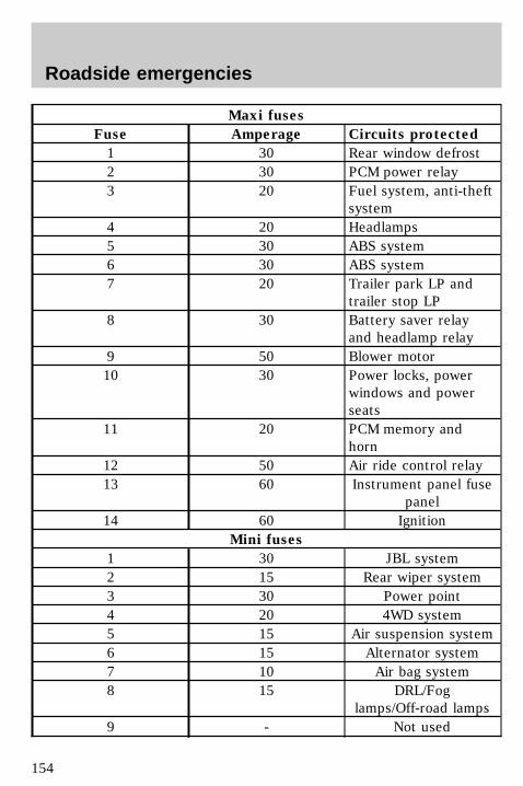
Maxi fuses
Fuse Amperage Circuits protected
1 30 Rear window defrost2 30 PCM power relay3 20 Fuel system, anti-theft
system4 20 Headlamps5 30 ABS system6 30 ABS system7 20 Trailer park LP and
trailer stop LP8 30 Battery saver relay
and headlamp relay9 50 Blower motor10 30 Power locks, power
windows and powerseats
11 20 PCM memory andhorn
12 50 Air ride control relay13 60 Instrument panel fuse
panel14 60 Ignition
Mini fuses
1 30 JBL system2 15 Rear wiper system3 30 Power point4 20 4WD system5 15 Air suspension system6 15 Alternator system7 10 Air bag system8 15 DRL/Fog
lamps/Off-road lamps9 - Not used
Roadside emergencies
154
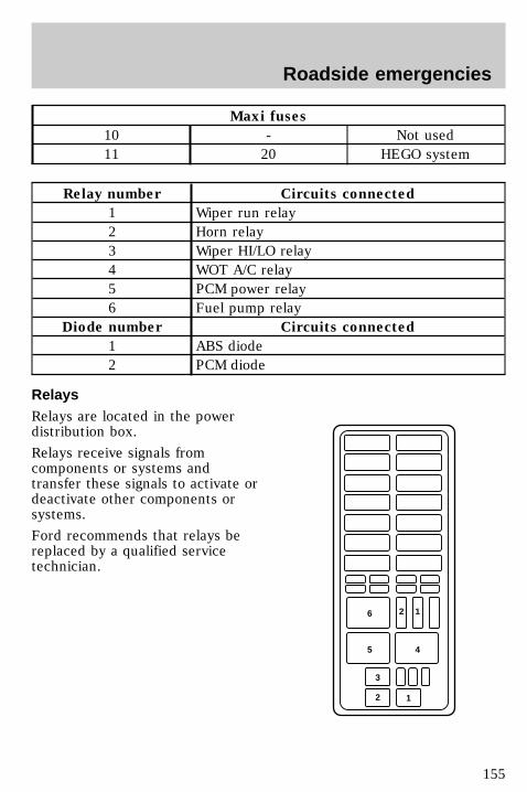
Maxi fuses
10 - Not used11 20 HEGO system
Relay number Circuits connected
1 Wiper run relay2 Horn relay3 Wiper HI/LO relay4 WOT A/C relay5 PCM power relay6 Fuel pump relay
Diode number Circuits connected
1 ABS diode2 PCM diode
RelaysRelays are located in the powerdistribution box.
Relays receive signals fromcomponents or systems andtransfer these signals to activate ordeactivate other components orsystems.
Ford recommends that relays bereplaced by a qualified servicetechnician.
6
5
3
2 1
4
2 1
uno_relays
Roadside emergencies
155
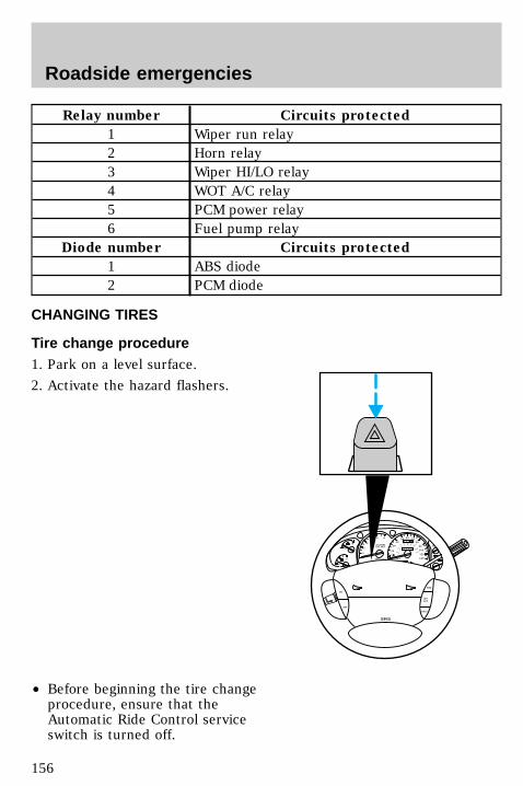
Relay number Circuits protected
1 Wiper run relay2 Horn relay3 Wiper HI/LO relay4 WOT A/C relay5 PCM power relay6 Fuel pump relay
Diode number Circuits protected
1 ABS diode2 PCM diode
CHANGING TIRES
Tire change procedure1. Park on a level surface.
2. Activate the hazard flashers.
• Before beginning the tire changeprocedure, ensure that theAutomatic Ride Control serviceswitch is turned off.
0
P R N D 2 1
UNLEADEDFUEL ONLY
RPMx1000
1
2
34
5 6
H
C
F
E
RSM
SETACC
COAST
OFF
ON
SRS
- +
H
H
L
L
0
20
10
30
4050 60 70
80
90
110
120
0 0 0 0 0 0
o o o o
km/h
10020
40
6080 100 120
140
160
180
uno_tire_change_procedure
Roadside emergencies
156
3. Engage the parking brake.
4. Place the automatictransmission gearshift in P (Park).Place the manual transmissiongearshift in 1 (First).
5. Block the diagonally oppositewheel.
6. Remove the jack and lugwrench.
7. Remove the jack handle locatedunder the rear seat.
Roadside emergencies
157
8. Assemble the jack handle to thelug wrench.
9. Insert the drive section of thejack handle into the actuator holeand turn counterclockwise untilthe cable is slack enough to allowthe spare tire to be pulledrearward from under the vehicle.
10. Slide spare tire rearward andremove retainer.
11. Insert tapered end of the lugwrench behind hubcaps and twistthem off.
12. Loosen the wheel lug nuts withthe lug wrench about one half turneach.
13. Position the jack on the lowersuspension arm to raise the frontwheel. Position the jack under therear axle to raise the rear wheel.
• Never use the differential asa jacking point.
14. Turn the jack handle clockwiseuntil the tire just clears theground.
15. Remove the wheel lug nuts andflat tire and install the spare tire.
Roadside emergencies
158
16. Install the lug nuts and tightenuntil snug.
17. Lower the vehicle and tightenthe lug nuts as shown.
18. Unblock the wheels and placethe flat tire, jack hhandle and lugwrench away.
Stowing flat tiresStow aluminum wheel and tirewith the valve stem down.
To stow largest flat tire, place itinside the vehicle and secure witha webbing retainer.
The conventional spare tire(if equipped)Your vehicle may be equipped witha conventional spare tire whichcan be used as a spare or a regulartire. This spare tire is identical tothe other tires on your vehicle,although the wheel style may notmatch.
The temporary spare tire(if equipped)Your vehicle may be equipped witha temporary spare tire. This spareis smaller than a regular tire and isintended for emergency use only.Us this spare when you get a flat
1
4
25
3
uno_stowing_flat_tires
uno_conventional_spare
uno_temporary_spare
Roadside emergencies
159
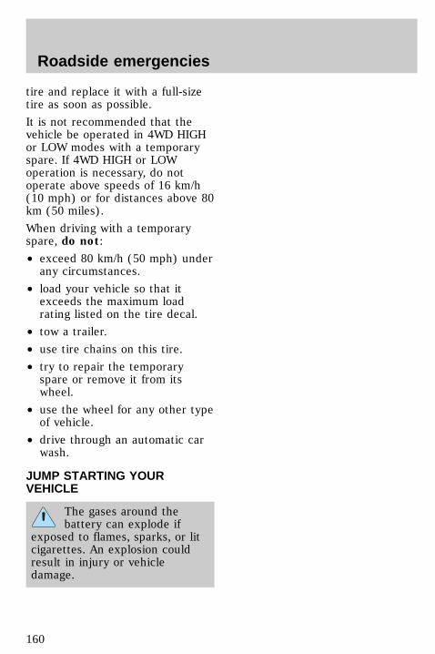
tire and replace it with a full-sizetire as soon as possible.
It is not recommended that thevehicle be operated in 4WD HIGHor LOW modes with a temporaryspare. If 4WD HIGH or LOWoperation is necessary, do notoperate above speeds of 16 km/h(10 mph) or for distances above 80km (50 miles).
When driving with a temporaryspare, do not:
• exceed 80 km/h (50 mph) underany circumstances.
• load your vehicle so that itexceeds the maximum loadrating listed on the tire decal.
• tow a trailer.
• use tire chains on this tire.
• try to repair the temporaryspare or remove it from itswheel.
• use the wheel for any other typeof vehicle.
• drive through an automatic carwash.
JUMP STARTING YOURVEHICLE
The gases around thebattery can explode if
exposed to flames, sparks, or litcigarettes. An explosion couldresult in injury or vehicledamage.
com_jump-starting.01
Roadside emergencies
160
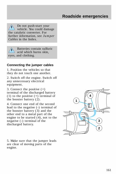
Do not push-start yourvehicle. You could damage
the catalytic converter. Forfurther information, see JumperCables in the Index.
Batteries contain sulfuricacid which burns skin,
eyes, and clothing.
Connecting the jumper cables1. Position the vehicles so thatthey do not touch one another.
2. Switch off the engine. Switch offany unnecessary electricalequipment.
3. Connect the positive (+)terminal of the discharged battery(1) to the positive (+) terminal ofthe booster battery (2).
4. Connect one end of the secondlead to the negative (-) terminal ofthe booster battery (3) and theother end to a metal part of theengine to be started (4), not to thenegative (-) terminal of thedischarged battery.
5. Make sure that the jumper leadsare clear of moving parts of theengine.
+
–
+
–
3
2
1
4
uno_connecting_cables
Roadside emergencies
161
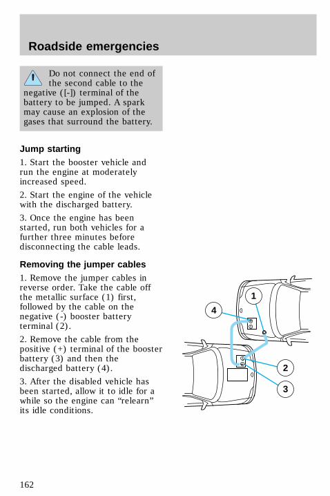
Do not connect the end ofthe second cable to the
negative ([-]) terminal of thebattery to be jumped. A sparkmay cause an explosion of thegases that surround the battery.
Jump starting1. Start the booster vehicle andrun the engine at moderatelyincreased speed.
2. Start the engine of the vehiclewith the discharged battery.
3. Once the engine has beenstarted, run both vehicles for afurther three minutes beforedisconnecting the cable leads.
Removing the jumper cables1. Remove the jumper cables inreverse order. Take the cable offthe metallic surface (1) first,followed by the cable on thenegative (-) booster batteryterminal (2).
2. Remove the cable from thepositive (+) terminal of the boosterbattery (3) and then thedischarged battery (4).
3. After the disabled vehicle hasbeen started, allow it to idle for awhile so the engine can “relearn”its idle conditions.
+
–
+
–
2
3
4
1
uno_jump_starting
com_removing_cables.01
uno_wrecker_towing
Roadside emergencies
162
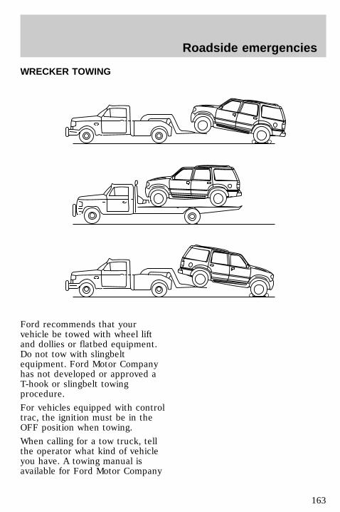
WRECKER TOWING
Ford recommends that yourvehicle be towed with wheel liftand dollies or flatbed equipment.Do not tow with slingbeltequipment. Ford Motor Companyhas not developed or approved aT-hook or slingbelt towingprocedure.
For vehicles equipped with controltrac, the ignition must be in theOFF position when towing.
When calling for a tow truck, tellthe operator what kind of vehicleyou have. A towing manual isavailable for Ford Motor Company
Roadside emergencies
163
for all authorized tow truckoperators. Have your tow truckdriver refer to this manual forproper hook-up and towingprocedures.
Neutral tow kit accessoryNeutral tow feature is an optionwhich can be activated at anydealership that has a Service BayDiagnostic System (SBDS). Whenactivated the feature may beenabled by following theinstruction located on the visor orthe headliner.
The feature is available on vehicleswith Control Trac and automatictransmission only. It is notavailable on vehicles withAll-Wheel Drive.
There are no wrecker orrecreational vehicle towingrestrictions on method or distanceif the above feature is activatedand enabled.
See your dealer for moreinformation.
uno_tow-kit
Roadside emergencies
164
SERVICE RECOMMENDATIONSTo help you service your vehicle:
• We highlight do-it-yourself itemsin the engine compartment foreasy location.
• As possible, we design parts thatcan be replaced without tools.
• We provide you with a “ServiceGuide” which makes trackingroutine service for your vehicleeasy.
If your vehicle requiresprofessional service, yourdealership can provide necessaryparts and service. Check your“Warranty Information Booklet” tofind out which parts and servicesare covered.
Use only recommended fuels,lubricants, fluids and service partsconforming to specifications.Motorcraft parts are designed andbuilt to provide the bestperformance in your vehicle.
Steps to take before performingmaintenance
Precautions when servicingyour vehicleBe especially careful wheninspecting or servicing yourvehicle. Here are some generalprecautions for your safety:
• Do not work on a hot engine.
• If you must work with theengine running, avoid wearingloose clothing or jewelry that
com_service_recommendations.01
uno_servicing_title
com_precautions_servicing.01
Maintenance and care
165
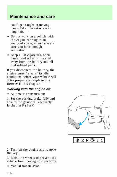
could get caught in movingparts. Take precautions withlong hair.
• Do not work on a vehicle withthe engine running in anenclosed space, unless you aresure you have enoughventilation.
• Keep all lit cigarettes, openflames and other lit materialaway from the battery and allfuel related parts.
If you disconnect the battery, theengine must “relearn” its idleconditions before your vehicle willdrive properly, as explained inBattery in this chapter.
Working with the engine off• Automatic transmission:
1. Set the parking brake fully andensure the gearshift is securelylatched in P (Park).
2. Turn off the engine and removethe key.
3. Block the wheels to prevent thevehicle from moving unexpectedly.
• Manual transmission:
uno_working_off
Maintenance and care
166
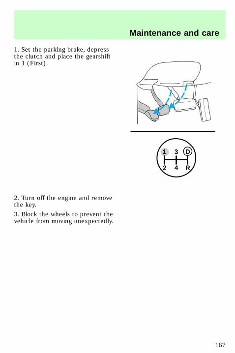
1. Set the parking brake, depressthe clutch and place the gearshiftin 1 (First).
2. Turn off the engine and removethe key.
3. Block the wheels to prevent thevehicle from moving unexpectedly.
1 3 D
2 4 R
uno_working_on
Maintenance and care
167

Working with the engine on• Automatic transmission:
1. Set the parking brake fully andensure the gearshift is securelylatched in P (Park).
2. Block the wheels to prevent thevehicle from moving unexpectedly.
Do not start your enginewith the air cleaner
removed and do not remove itwhile the engine is running.
Maintenance and care
168
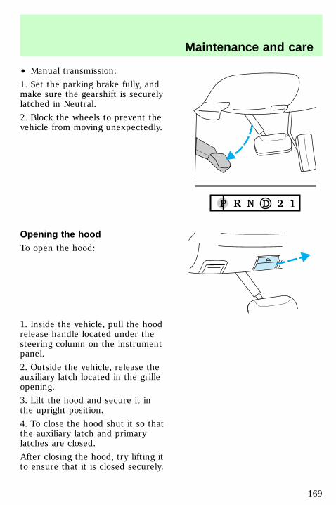
• Manual transmission:
1. Set the parking brake fully, andmake sure the gearshift is securelylatched in Neutral.
2. Block the wheels to prevent thevehicle from moving unexpectedly.
Opening the hoodTo open the hood:
1. Inside the vehicle, pull the hoodrelease handle located under thesteering column on the instrumentpanel.
2. Outside the vehicle, release theauxiliary latch located in the grilleopening.
3. Lift the hood and secure it inthe upright position.
4. To close the hood shut it so thatthe auxiliary latch and primarylatches are closed.
After closing the hood, try lifting itto ensure that it is closed securely.
uno_opening_hood
com_engine-comp
Maintenance and care
169
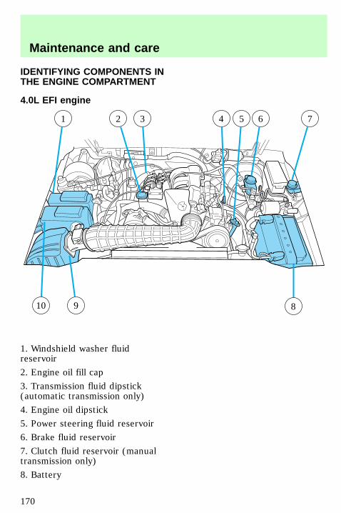
IDENTIFYING COMPONENTS INTHE ENGINE COMPARTMENT
4.0L EFI engine
1. Windshield washer fluidreservoir
2. Engine oil fill cap
3. Transmission fluid dipstick(automatic transmission only)
4. Engine oil dipstick
5. Power steering fluid reservoir
6. Brake fluid reservoir
7. Clutch fluid reservoir (manualtransmission only)
8. Battery
10
1 2 3 5 6 74
89
com_4.0L-ohv
Maintenance and care
170
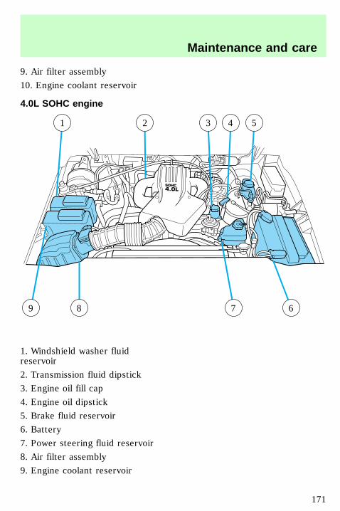
9. Air filter assembly
10. Engine coolant reservoir
4.0L SOHC engine
1. Windshield washer fluidreservoir
2. Transmission fluid dipstick
3. Engine oil fill cap
4. Engine oil dipstick
5. Brake fluid reservoir
6. Battery
7. Power steering fluid reservoir
8. Air filter assembly
9. Engine coolant reservoir
9
1 3 42 5
8 67
com_4.0L-ohc
com_5.0L
Maintenance and care
171

5.0L engine
1. Engine coolant reservoir
2. Windshield washer fluidreservoir
3. Engine oil fill cap
4. Transmission fluid dipstick
5. Brake fluid reservoir
6. Power distribution box
7. Battery
8. Radiator cap
9. Power steering fluid reservoir
10. Engine oil dipstick
11. Ignition coil packs
12. Air filter assembly
1
2 3 6
7
54
81011 912
com_check-add_oil.01
Maintenance and care
172
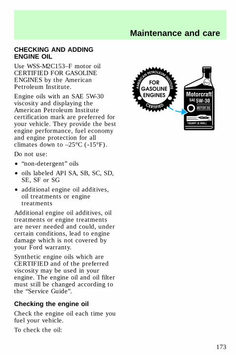
CHECKING AND ADDINGENGINE OILUse WSS-M2C153–F motor oilCERTIFIED FOR GASOLINEENGINES by the AmericanPetroleum Institute.
Engine oils with an SAE 5W-30viscosity and displaying theAmerican Petroleum Institutecertification mark are preferred foryour vehicle. They provide the bestengine performance, fuel economyand engine protection for allclimates down to –25°C (-15°F).
Do not use:
• “non-detergent” oils
• oils labeled API SA, SB, SC, SD,SE, SF or SG
• additional engine oil additives,oil treatments or enginetreatments
Additional engine oil additives, oiltreatments or engine treatmentsare never needed and could, undercertain conditions, lead to enginedamage which is not covered byyour Ford warranty.
Synthetic engine oils which areCERTIFIED and of the preferredviscosity may be used in yourengine. The engine oil and oil filtermust still be changed according tothe “Service Guide”.
Checking the engine oilCheck the engine oil each time youfuel your vehicle.
To check the oil:
uno_checking_engine_oil
Maintenance and care
173
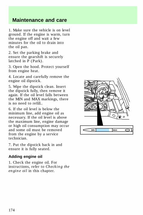
1. Make sure the vehicle is on levelground. If the engine is warm, turnthe engine off and wait a fewminutes for the oil to drain intothe oil pan.
2. Set the parking brake andensure the gearshift is securelylatched in P (Park).
3. Open the hood. Protect yourselffrom engine heat.
4. Locate and carefully remove theengine oil dipstick.
5. Wipe the dipstick clean. Insertthe dipstick fully, then remove itagain. If the oil level falls betweenthe MIN and MAX markings, thereis no need to refill..
6. If the oil level is below theminimum line, add engine oil asnecessary. If the oil level is abovethe maximum line, engine damageor high oil consumption may occurand some oil must be removedfrom the engine by a servicetechnician.
7. Put the dipstick back in andensure it is fully seated.
Adding engine oil1. Check the engine oil. Forinstructions, refer to Checking theengine oil in this chapter.
MAXMIN
com_adding_engine_oil.01
Maintenance and care
174
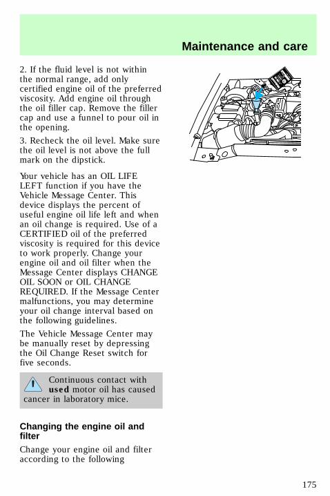
2. If the fluid level is not withinthe normal range, add onlycertified engine oil of the preferredviscosity. Add engine oil throughthe oil filler cap. Remove the fillercap and use a funnel to pour oil inthe opening.
3. Recheck the oil level. Make surethe oil level is not above the fullmark on the dipstick.
Your vehicle has an OIL LIFELEFT function if you have theVehicle Message Center. Thisdevice displays the percent ofuseful engine oil life left and whenan oil change is required. Use of aCERTIFIED oil of the preferredviscosity is required for this deviceto work properly. Change yourengine oil and oil filter when theMessage Center displays CHANGEOIL SOON or OIL CHANGEREQUIRED. If the Message Centermalfunctions, you may determineyour oil change interval based onthe following guidelines.
The Vehicle Message Center maybe manually reset by depressingthe Oil Change Reset switch forfive seconds.
Continuous contact withused motor oil has caused
cancer in laboratory mice.
Changing the engine oil andfilterChange your engine oil and filteraccording to the following
com_oil_and_filter_change.01
Maintenance and care
175
kilometers (mileage) and timerequirements, whichever occursfirst:
• Normal Schedule – 8,000 km(5,000 miles) or six months.
• Severe Duty Schedule – 5,000km (3,000 miles) or threemonths. Severe duty operationwould include extensive idling,trailer towing, driving in severedust and police, taxi or deliveryservice.
Ford production and aftermarket(Motorcraft) oil filters are designedfor added engine protection andlong life. If a replacement oil filteris used that does not meet Fordmaterial and design specifications,startup engine noises or knockmay be experienced.
It is recommended you use theappropriate Motorcraft oil filter (oranother brand meeting Fordspecifications) for your engineapplication.
DRIVELINE UNIVERSAL JOINTAND SLIP YOKEThe universal joints standard withyour vehicle do not requirelubrication. If the originalequipment universal joints arereplaced with universal jointsequipped with grease fittings,lubrication will be necessary at theintervals shown in the “ServiceGuide” supplement.
com_universal_joint.01
com_checking-adding_fluid.01
Maintenance and care
176
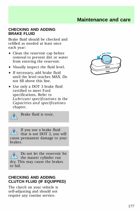
CHECKING AND ADDINGBRAKE FLUIDBrake fluid should be checked andrefilled as needed at least onceeach year:
• Clean the reservoir cap beforeremoval to prevent dirt or waterfrom entering the reservoir.
• Visually inspect the fluid level.
• If necessary, add brake fluiduntil the level reaches MAX. Donot fill above this line.
• Use only a DOT 3 brake fluidcertified to meet Fordspecifications. Refer toLubricant specifications in theCapacities and specificationschapter.
Brake fluid is toxic.
If you use a brake fluidthat is not DOT 3, you will
cause permanent damage to yourbrakes.
Do not let the reservoir forthe master cylinder run
dry. This may cause the brakesto fail.
CHECKING AND ADDINGCLUTCH FLUID (IF EQUIPPED)The clutch on your vehicle isself-adjusting and should notrequire any routine service.
MAX
MIN
uno_checking_adding_clutch
Maintenance and care
177
During normal operation, the fluidlevel in the clutch fluid reservoirwill slowly rise. If the fluid leveldrops, maintain the fluid level atthe reservoir indicator.
Use only DOT 3 brake fluiddesigned to meet Fordspecifications. Refer to theCapacities and specificationschapter.
1. Clean the reservoir cap beforeremoval to prevent contaminantsfrom entering the reservoir.
2. Remove the cap.
3. Add fluid until the level reachesthe FULL line.
CHECKING AND ADDINGWASHER FLUID
Important information aboutwasher fluidIn freezing weather (temperaturesbelow 0°C [32°F]), washer fluidcontaining a small amount ofantifreeze is to be used. State orlocal regulations on volatile organiccompounds may restrict the use ofmethanol, a common antifreezeadditive. Use a non-methanolantifreeze in freezing weather onlyif the fluid does not damage thepaint finish, wiper blades orwasher system.
Windshield washer fluidcontains methanol which is
poisonous.
uno_washer_fluid_title
uno_what_you_should_know
uno_reservoir_washer_fluid
Maintenance and care
178
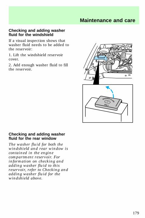
Checking and adding washerfluid for the windshieldIf a visual inspection shows thatwasher fluid needs to be added tothe reservoir:
1. Lift the windshield reservoircover.
2. Add enough washer fluid to fillthe reservoir.
Checking and adding washerfluid for the rear windowThe washer fluid for both thewindshield and rear window iscontained in the enginecompartment reservoir. Forinformation on checking andadding washer fluid to thisreservoir, refer to Checking andadding washer fluid for thewindshield above.
WASHER FLUID
ONLY
uno_liftgate_washer_fluid
uno_title-coolant
Maintenance and care
179
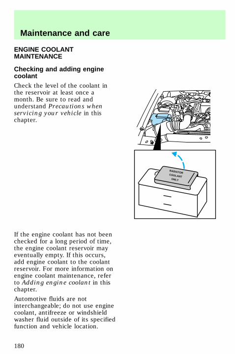
ENGINE COOLANTMAINTENANCE
Checking and adding enginecoolantCheck the level of the coolant inthe reservoir at least once amonth. Be sure to read andunderstand Precautions whenservicing your vehicle in thischapter.
If the engine coolant has not beenchecked for a long period of time,the engine coolant reservoir mayeventually empty. If this occurs,add engine coolant to the coolantreservoir. For more information onengine coolant maintenance, referto Adding engine coolant in thischapter.
Automotive fluids are notinterchangeable; do not use enginecoolant, antifreeze or windshieldwasher fluid outside of its specifiedfunction and vehicle location.
RADIATORCOOLANT
ONLY
uno_checking-adding-coolant
com_adding_coolant.01
Maintenance and care
180
When adding engine coolantFord recommends Ford PremiumCooling System Fluid, which is anoptimized formula that will protectall metals and rubber elastomersused in Ford engines for four yearsor 80,000 km (50,000 miles).
It is neither necessary norrecommended to use supplementalcoolant additives in yourgasoline-powered vehicle. Theseadditives may harm your enginecooling system.
When you change or add enginecoolant, it is important to maintainengine coolant concentrationbetween 40% (-24°C [-11°F]) and60% (-52°C [-62°F]), depending onyour local climate conditions.
A coolant concentration below 40%will result in a loss of freezeprotection. A concentration above60% may cause the engine tooverheat on a warm day.
Refer to Lubricant specificationsin the Specifications andcapacities chapter. Use only apremium nationally-recognizedbrand name engine coolant orequivalent.
Always dispose of usedautomotive fluids in a responsiblemanner. Follow your community’sstandards for disposing of thesetypes of fluids. Call your localrecycling center to find out moreabout recycling automotive fluids.
com_recycled_coolant.01
Maintenance and care
181
Recycled engine coolantFord Motor Company recommendsthat Ford and Lincoln-Mercurydealers use recycled enginecoolant produced byFord-approved processes. Not allcoolant recycling processesproduce coolant which meets Fordspecification ESE-M97B44–A, anduse of such coolant may harmengine and cooling systemcomponents.
Always dispose of usedautomotive fluids in a responsiblemanner. Follow your community’sregulations and standards forrecycling and disposing ofautomotive fluids.
Coolant refill capacityTo find out how much fluid yourvehicle’s cooling system can hold,refer to Refill capacities in theCapacities and specificationschapter.
Have your dealer check the enginecooling system for leaks if youhave to add more than a liter(quart) of engine coolant permonth.
Severe winter climateIf you drive in extremely coldclimates [less than –36°C (–34°F)],it may be necessary to increase thecoolant concentration above 50%.Refer to the chart on the coolantcontainer to ensure the coolantconcentration in your vehicle issuch that the coolant will not
com_refill_capacity.01
com_winter_climate.01
Maintenance and care
182
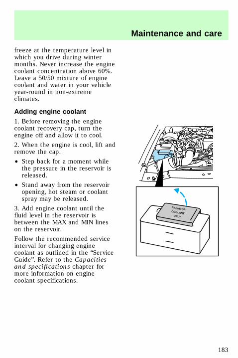
freeze at the temperature level inwhich you drive during wintermonths. Never increase the enginecoolant concentration above 60%.Leave a 50/50 mixture of enginecoolant and water in your vehicleyear-round in non-extremeclimates.
Adding engine coolant1. Before removing the enginecoolant recovery cap, turn theengine off and allow it to cool.
2. When the engine is cool, lift andremove the cap.
• Step back for a moment whilethe pressure in the reservoir isreleased.
• Stand away from the reservoiropening, hot steam or coolantspray may be released.
3. Add engine coolant until thefluid level in the reservoir isbetween the MAX and MIN lineson the reservoir.
Follow the recommended serviceinterval for changing enginecoolant as outlined in the “ServiceGuide”. Refer to the Capacitiesand specifications chapter formore information on enginecoolant specifications.
RADIATORCOOLANT
ONLY
uno_adding_engine_coolant
com_checking_hoses.01
Maintenance and care
183
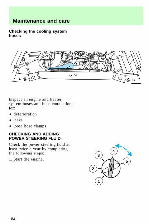
Checking the cooling systemhoses
Inspect all engine and heatersystem hoses and hose connectionsfor:
• deterioration
• leaks
• loose hose clamps
CHECKING AND ADDINGPOWER STEERING FLUIDCheck the power steering fluid atleast twice a year by completingthe following steps:
1. Start the engine.3
2
1
5
4
uno_checking_adding_power_st
Maintenance and care
184
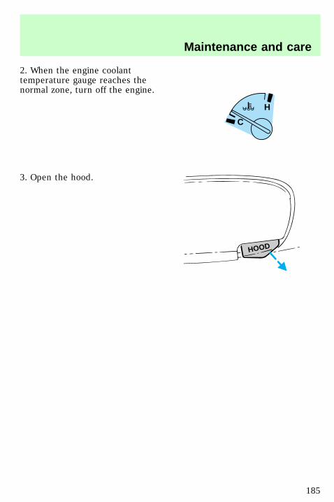
2. When the engine coolanttemperature gauge reaches thenormal zone, turn off the engine.
3. Open the hood.
H
C
HOOD
Maintenance and care
185
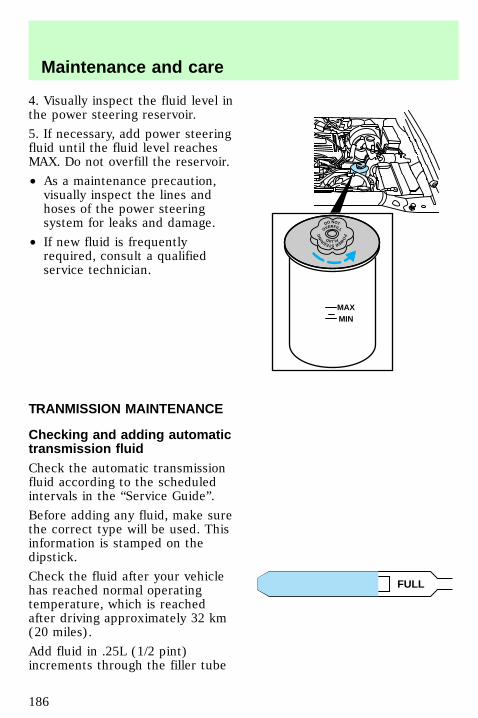
4. Visually inspect the fluid level inthe power steering reservoir.
5. If necessary, add power steeringfluid until the fluid level reachesMAX. Do not overfill the reservoir.
• As a maintenance precaution,visually inspect the lines andhoses of the power steeringsystem for leaks and damage.
• If new fluid is frequentlyrequired, consult a qualifiedservice technician.
TRANMISSION MAINTENANCE
Checking and adding automatictransmission fluidCheck the automatic transmissionfluid according to the scheduledintervals in the “Service Guide”.
Before adding any fluid, make surethe correct type will be used. Thisinformation is stamped on thedipstick.
Check the fluid after your vehiclehas reached normal operatingtemperature, which is reachedafter driving approximately 32 km(20 miles).
Add fluid in .25L (1/2 pint)increments through the filler tube
MAXMIN
DO NOT
OVERFILL
PO
W
ERSTEERING FLUID
ADD FULL
uno_trans_fluid_title
com_checking-adding_fluid.02
Maintenance and care
186
until the level is at the correctarea on the dipstick. If an overfilloccurs, excess fluid should beremoved by a qualified technician.
Checking and adding manualtransmission fluid (if equipped)1. Clean the filler plug.
2. Remove the filler plug andinspect the fluid level.
• The fluid level should be at thebottom of the opening.
3. Add enough fluid through thefiller opening so that the fluid levelis at the bottom of the opening.
Use only fluid that meets Fordspecifications. Refer to theCapacities and specificationschapter for more information onmanual transmission fluid.
Driveline universal joint and slipyokeThe universal joints standard withyour vehicle do not requirelubrication. If the originalequipment universal joints arereplaced with universal jointsequipped with grease fittings,lubrication will be necessary at theintervals shown in the ServiceGuide supplement.
Constant velocity or doublecarden joint (if equipped)This component may be fitted witha flush-type grease fitting thatrequires an adaptor to permitproper lubrication. If replaced,
uno_manual_trans_fluid
uno_driveline1
uno_constant_velocity
Maintenance and care
187
lubricate the driveline jointaccording to the maintenanceintervals specified in the ServiceGuide.
CHECKING AND ADDINGDIFFERENTIAL FLUID(IF EQUIPPED)To check and add differential fluid,follow these steps:
1. Clean the filler plug.
2. Remove the filler plug andinspect fluid level.
• Fluid level should be at thebottom of the opening.
The rear axle is filled withsynthetic lubricant and will notrequire a lubricant change duringthe life of the vehicle unless therear axle has been submerged inwater. In addition, rear axlelubricant quantities need not bechecked or changed unless a leakis suspected or repair is needed.
BATTERY MAINTENANCE
Important battery informationIf the original equipmentmaintenance —free battery needs
uno_differentail_fluid
uno_battery_title
uno_info_battery
Maintenance and care
188
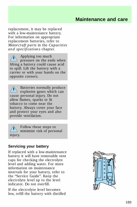
replacement, it may be replacedwith a low-maintenance battery.For information on appropriatereplacement batteries, refer toMotorcraft parts in the Capacitiesand specifications chapter.
Applying too muchpressure on the ends when
lifting a battery could cause acidto spill. Lift the battery with acarrier or with your hands on theopposite corners.
Batteries normally produceexplosive gases which can
cause personal injury. Do notallow flames, sparks or littobacco to come near thebattery. Always cover your faceand protect your eyes and alsoprovide ventilation.
Follow these steps tominimize risk of personal
injury.
Servicing your batteryIf replaced with a low-maintenancebattery it will have removable ventcaps for checking the electrolytelevel and adding water. For moreinformation on maintenanceintervals for your battery, refer tothe “Service Guide”. Keep theelectrolyte level up to the levelindicator. Do not overfill.
If the electrolyte level becomeslow, refill the battery with distilled
uno_servicing_battery
Maintenance and care
189
water. If necessary, distilled watermay be substituted with tap waterthat is not hard and does not havehigh mineral or alkali content. Ifthe battery needs water often,have the charging system checkedfor a possible malfunction.
Relearning the idle functionBecause your vehicle’s engine iselectronically controlled, somecontrol conditions are maintainedby power from the battery. Whenthe battery is disconnected or anew battery is installed, thecomputer must “relearn” its idleconditions before your vehicle candrive properly. To begin thisprocess:
Maintenance and care
190
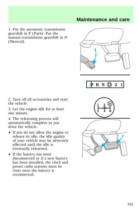
1. Put the automatic transmissiongearshift in P (Park). Put themanual transmission gearshift in N(Neutral).
2. Turn off all accessories and startthe vehicle.
3. Let the engine idle for at leastone minute.
4. The relearning process willautomatically complete as youdrive the vehicle.
• If you do not allow the engine torelearn its idle, the idle qualityof your vehicle may be adverselyaffected until the idle iseventually relearned.
• If the battery has beendisconnected or if a new batteryhas been installed, the clock andpreset radio stations must bereset once the battery isreconnected.
1
2 4 R
3 D
Maintenance and care
191
Always dispose of automotivebatteries in a responsible manner.Follow your community’s localstandards for disposal. Call yourlocal recycling center to find outmore about recycling automotivebatteries.
Battery saver control featureYour vehicle is equipped with abattery saver control featuredesigned to prevent your batteryfrom accidental wear down due todoors left ajar. For information onthe system and its function, referto the Controls and featureschapter.
AIR CLEANER FILTERMAINTENANCERefer to the “Service Guide” forthe appropriate intervals forchanging the air cleaner filter.
Do not start your enginewith the air cleaner
removed and do not remove itwhile the engine is running.
uno_saver_battery_feature
uno_air_filter_maint
uno_changing_air_filter
Maintenance and care
192
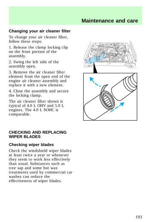
Changing your air cleaner filterTo change your air cleaner filter,follow these steps:
1. Release the clamp locking clipon the front portion of theassembly.
2. Swing the left side of theassembly open.
3. Remove the air cleaner filterelement from the open end of theengine air cleaner assembly andreplace it with a new element.
4. Close the assembly and securethe locking clamp.
The air cleaner filter shown istypical of 4.0 L OHV and 5.0 Lengines. The 4.0 L SOHC iscomparable.
CHECKING AND REPLACINGWIPER BLADES
Checking wiper bladesCheck the windshield wiper bladesat least twice a year or wheneverthey seem to work less effectivelythan usual. Substances such astree sap and some hot waxtreatments used by commercial carwashes can reduce theeffectiveness of wiper blades.
uno_wipers_title
uno_checking_wipers
Maintenance and care
193
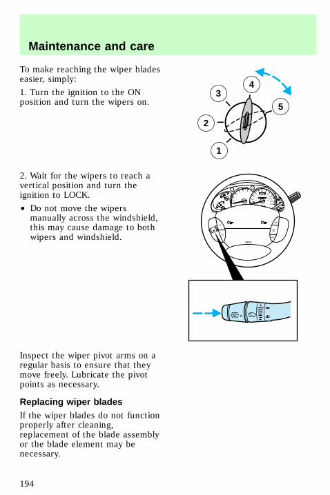
To make reaching the wiper bladeseasier, simply:
1. Turn the ignition to the ONposition and turn the wipers on.
2. Wait for the wipers to reach avertical position and turn theignition to LOCK.
• Do not move the wipersmanually across the windshield,this may cause damage to bothwipers and windshield.
Inspect the wiper pivot arms on aregular basis to ensure that theymove freely. Lubricate the pivotpoints as necessary.
Replacing wiper bladesIf the wiper blades do not functionproperly after cleaning,replacement of the blade assemblyor the blade element may benecessary.
3
2
1
5
4
0
P R N D 2 1
RPMx1000
1
2
34
5 6
H
C
F
E
RSM
SETACC
COAST
OFF
ON
SRS
- +
H
H
L
L
0
20
10
30
4050 60 70
80
90
110
120
0 0 0 0 0 0
o o o o
km/h
10020
40
6080 100 120
140
160
180
uno_replacing_wipers
Maintenance and care
194
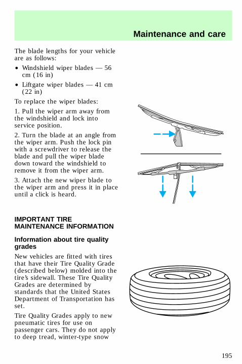
The blade lengths for your vehicleare as follows:
• Windshield wiper blades — 56cm (16 in)
• Liftgate wiper blades — 41 cm(22 in)
To replace the wiper blades:
1. Pull the wiper arm away fromthe windshield and lock intoservice position.
2. Turn the blade at an angle fromthe wiper arm. Push the lock pinwith a screwdriver to release theblade and pull the wiper bladedown toward the windshield toremove it from the wiper arm.
3. Attach the new wiper blade tothe wiper arm and press it in placeuntil a click is heard.
IMPORTANT TIREMAINTENANCE INFORMATION
Information about tire qualitygradesNew vehicles are fitted with tiresthat have their Tire Quality Grade(described below) molded into thetire’s sidewall. These Tire QualityGrades are determined bystandards that the United StatesDepartment of Transportation hasset.
Tire Quality Grades apply to newpneumatic tires for use onpassenger cars. They do not applyto deep tread, winter-type snow
uno_title_tires
com_about_tire_grades.01
Maintenance and care
195
tires, space-saver or temporary usespare tires, tires with nominal rimdiameters of 10 to 12 inches orlimited production tires as definedin Title 49 Code of FederalRegulations Part 575.104(c)(2).
U.S. Department ofTransportation-Tire qualitygrades: The U.S. Department ofTransportation requires Ford togive you the following informationabout tire grades exactly as thegovernment has written it.
TreadwearThe treadwear grade is acomparative rating based on thewear rate of the tire when testedunder controlled conditions on aspecified government test course.For example, a tire grade 150would wear one and one-half (11/2) times as well on thegovernment course as a tire grade100. The relative performance oftires depends upon the actualconditions of their use, however,and may depart significantly fromthe norm due to variations indriving habits, service practices,and differences in roadcharacteristics and climate.
Traction A B CThe traction grades, from highestto lowest are A, B, and C, and theyrepresent the tire’s ability to stopon wet pavement as measuredunder test surfaces of asphalt andconcrete. A tire marked C mayhave poor traction performance.
com_treadwear.01
com_traction_abc.01
Maintenance and care
196
Warning: The traction gradeassigned to this tire is based onbraking (straightahead) tractiontests and does not includecornering (turning) traction.
Temperature A B CThe temperature grades are A (thehighest), B, and C, representingthe tire’s resistance to thegeneration of heat and its ability todissipate heat when tested undercontrolled conditions on aspecified indoor laboratory testwheel. Sustained high temperaturecan cause the material of the tireto degenerate and reduce tire life,and excessive temperature canlead to sudden tire failure. Thegrade C corresponds to a level ofperformance which all passengercar tires must meet under theFederal Motor Vehicle SafetyStandard No. 109. Grades B and Arepresent higher levels ofperformance on the laboratory testwheel than the minimum requiredby law.
The temperature grade forthis tire is established for a
tire that is properly inflated andnot overloaded. Excessive speed,underinflation, or excessiveloading, either separately or incombination, can cause heatbuildup and possible tire failure.
Checking the tire pressureCheck the tire pressureperiodically and inflate tires as
com_temperature_abc.01
uno_pressure_tires
Maintenance and care
197
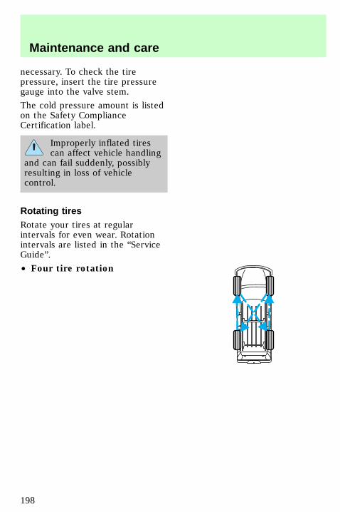
necessary. To check the tirepressure, insert the tire pressuregauge into the valve stem.
The cold pressure amount is listedon the Safety ComplianceCertification label.
Improperly inflated tirescan affect vehicle handling
and can fail suddenly, possiblyresulting in loss of vehiclecontrol.
Rotating tiresRotate your tires at regularintervals for even wear. Rotationintervals are listed in the “ServiceGuide”.
• Four tire rotation
uno_rotating_tires
Maintenance and care
198
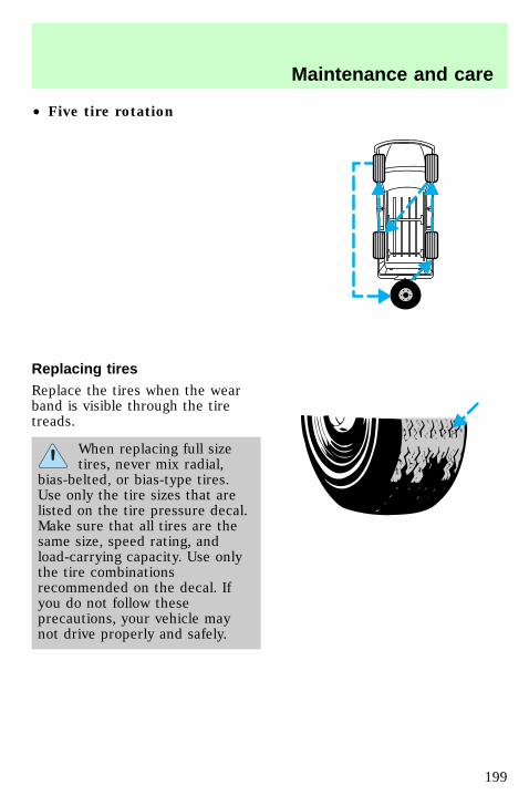
• Five tire rotation
Replacing tiresReplace the tires when the wearband is visible through the tiretreads.
When replacing full sizetires, never mix radial,
bias-belted, or bias-type tires.Use only the tire sizes that arelisted on the tire pressure decal.Make sure that all tires are thesame size, speed rating, andload-carrying capacity. Use onlythe tire combinationsrecommended on the decal. Ifyou do not follow theseprecautions, your vehicle maynot drive properly and safely.
uno_types_tires
Maintenance and care
199
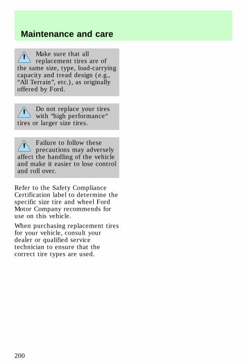
Make sure that allreplacement tires are of
the same size, type, load-carryingcapacity and tread design (e.g.,“All Terrain”, etc.), as originallyoffered by Ford.
Do not replace your tireswith “high performance“
tires or larger size tires.
Failure to follow theseprecautions may adversely
affect the handling of the vehicleand make it easier to lose controland roll over.
Refer to the Safety ComplianceCertification label to determine thespecific size tire and wheel FordMotor Company recommends foruse on this vehicle.
When purchasing replacement tiresfor your vehicle, consult yourdealer or qualified servicetechnician to ensure that thecorrect tire types are used.
uno_snow_tires
Maintenance and care
200
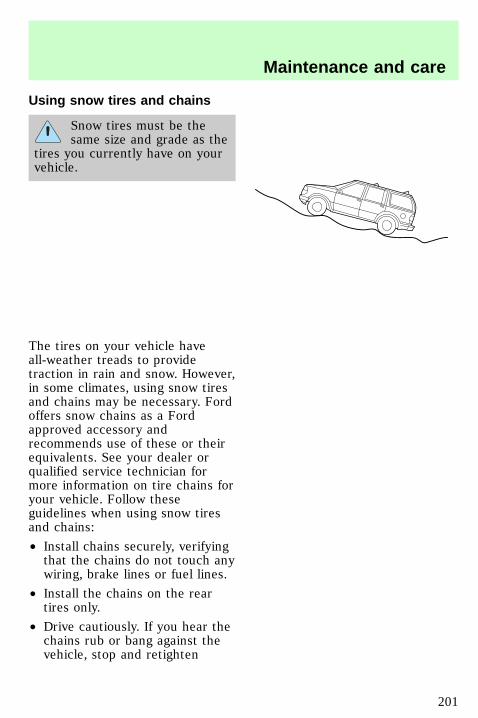
Using snow tires and chains
Snow tires must be thesame size and grade as the
tires you currently have on yourvehicle.
The tires on your vehicle haveall-weather treads to providetraction in rain and snow. However,in some climates, using snow tiresand chains may be necessary. Fordoffers snow chains as a Fordapproved accessory andrecommends use of these or theirequivalents. See your dealer orqualified service technician formore information on tire chains foryour vehicle. Follow theseguidelines when using snow tiresand chains:
• Install chains securely, verifyingthat the chains do not touch anywiring, brake lines or fuel lines.
• Install the chains on the reartires only.
• Drive cautiously. If you hear thechains rub or bang against thevehicle, stop and retighten
Maintenance and care
201
them. If this does not work,remove the chains to preventvehicle damage.
• Avoid overloading your vehicle.
• Remove the tire chains whenthey are no longer needed. Donot use chains on dry roads.
• The suspension insulation andbumpers will help preventvehicle damage. Do not removethese components from thevehicle when using snow tiresand chains.
If equipped with 110 cm (17 inch)tires, your vehicle will notaccommodate snow chains. Consultyour dealer for information onother Ford approved methods oftraction control.
IMPORTANT FUELINFORMATION
Important safety precautions
Do not overfill the fueltank. The pressure in an
overfilled tank may causeleakage and lead to fuel sprayand fire.
If you do not use theproper fuel cap, the
pressure in the fuel tank candamage the fuel system or causeit to work improperly in acollision.
uno_fuel_info_title
com_important_precautions.06
Maintenance and care
202
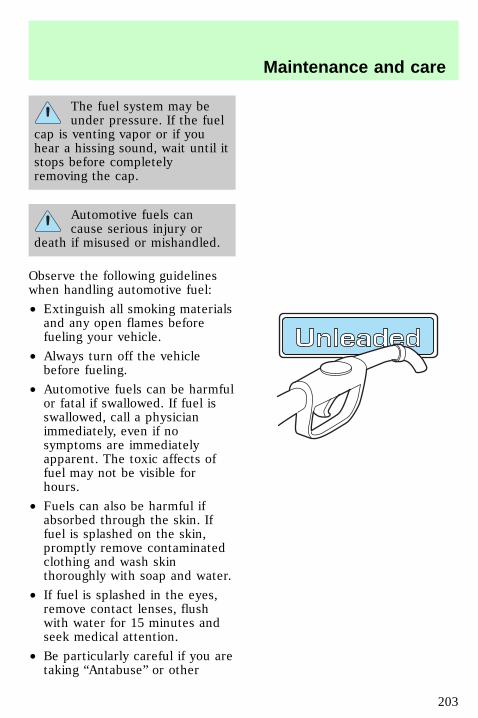
The fuel system may beunder pressure. If the fuel
cap is venting vapor or if youhear a hissing sound, wait until itstops before completelyremoving the cap.
Automotive fuels cancause serious injury or
death if misused or mishandled.
Observe the following guidelineswhen handling automotive fuel:
• Extinguish all smoking materialsand any open flames beforefueling your vehicle.
• Always turn off the vehiclebefore fueling.
• Automotive fuels can be harmfulor fatal if swallowed. If fuel isswallowed, call a physicianimmediately, even if nosymptoms are immediatelyapparent. The toxic affects offuel may not be visible forhours.
• Fuels can also be harmful ifabsorbed through the skin. Iffuel is splashed on the skin,promptly remove contaminatedclothing and wash skinthoroughly with soap and water.
• If fuel is splashed in the eyes,remove contact lenses, flushwith water for 15 minutes andseek medical attention.
• Be particularly careful if you aretaking “Antabuse” or other
Maintenance and care
203
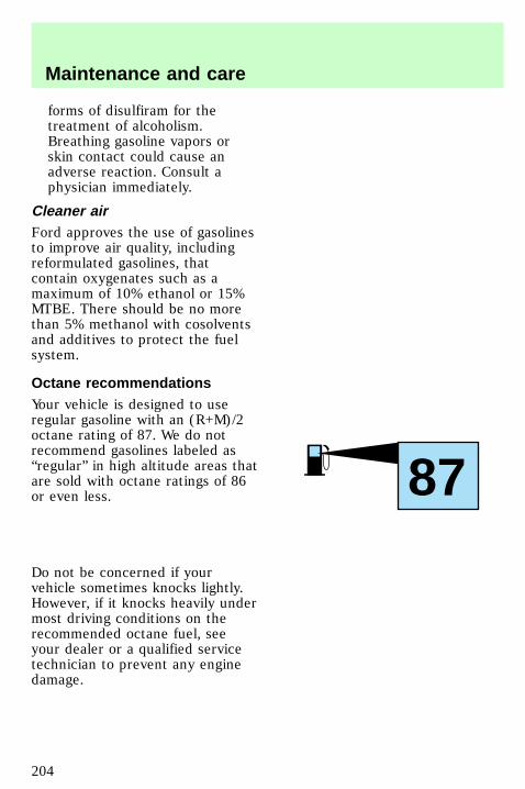
forms of disulfiram for thetreatment of alcoholism.Breathing gasoline vapors orskin contact could cause anadverse reaction. Consult aphysician immediately.
Cleaner airFord approves the use of gasolinesto improve air quality, includingreformulated gasolines, thatcontain oxygenates such as amaximum of 10% ethanol or 15%MTBE. There should be no morethan 5% methanol with cosolventsand additives to protect the fuelsystem.
Octane recommendationsYour vehicle is designed to useregular gasoline with an (R+M)/2octane rating of 87. We do notrecommend gasolines labeled as“regular” in high altitude areas thatare sold with octane ratings of 86or even less.
Do not be concerned if yourvehicle sometimes knocks lightly.However, if it knocks heavily undermost driving conditions on therecommended octane fuel, seeyour dealer or a qualified servicetechnician to prevent any enginedamage.
87
com_cleaner_air.01
com_octane_recommendations.01
com_fuel_quality.01
Maintenance and care
204
Fuel qualityIf you are experiencing starting,rough idle or hesitation problemstry a different brand of fuel. If thecondition persists, see your dealeror a qualified service technician.
The American AutomobileManufacturers Association (AAMA)issued a gasoline specification toprovide information on high qualityfuels that optimize theperformance of your vehicle. Werecommend the use of gasolinesthat meet the AAMA specificationif they are available.
It should not be necessary to addany aftermarket products to yourfuel tank if you continue to use ahigh-quality fuel.
Choosing the right fuelUse only UNLEADED FUEL. Theuse of leaded fuel is prohibited bylaw and could damage yourvehicle. The damage may not becovered by your warranty.
Your vehicle was not designed touse fuel containingmanganese-based additives such asMMT. Additionally, vehiclescertified to California emissionstandards (indicated on theunderhood Vehicle EmissionsControl Information label) aredesigned to operate on Californiareformulated gasolines. IfCalifornia reformulated gasoline isnot available when you refuel, yourvehicle can be operated onnon-California fuels. However, even
com_choosing_fuel.01
Maintenance and care
205

though your engine will performadequately on other gasolines, theperformance of the emissioncontrol devices and systems maybe adversely affected. Repair ofdamage caused by using a fuel thatyour vehicle was not designed formay not be covered by yourwarranty.
Calculating fuel economyTo accurately calculate yourvehicle’s fuel economy:
1. Fill the tank completely andrecord the initial odometerreading.
2. Each time you fill the tank,record the amount of fuel added(in liters or gallons).
3. After at least three to five fueltank fill-ups, fill the fuel tank andrecord the current mileagereading.
4. Use one of the followingequations to calculate fueleconomy.
Liters used x 100 4 Totalkilometers traveled
Total miles traveled 4 Totalgallons used
Keep a record for at least onemonth. This will provide anaccurate estimate of the vehicle’sfuel economy.
EMISSION CONTROL SYSTEMYour vehicle is equipped withvarious emission control
com_calculating_economy.01
com_emission.ses
Maintenance and care
206
components and a catalyticconverter which will enable yourvehicle to comply with applicableexhaust emission standards. Tomake sure that the catalyticconverter and other emissioncontrol components continue towork properly:
• Use only unleaded fuel.
• Avoid running out of fuel.
• Do not turn off the ignitionwhile your vehicle is moving,especially at high speeds.
• Have the services listed in your“Service Guide” performedaccording to the specifiedschedule.
The Scheduled MaintenanceServices listed in the “ServiceGuide” are required because theyare considered essential to the lifeand performance of your vehicleand to its emissions system.
If other than Ford, Motorcraft orFord authorized parts are used formaintenance replacements or forservice of components affectingemission control such non-Fordparts should be equivalent togenuine Ford Motor Companyparts in performance anddurability.
Do not park, idle, or driveyour vehicle in dry grass
or other dry ground cover. Theemission system heats up theengine compartment and exhaustsystem, which can start a fire.
Maintenance and care
207
Watch for fluid leaks, strangeodors, smoke, loss of oil pressure,the charging system warning light,the “Service Engine Soon” light orthe temperature warning light.These events could indicate thatthe emission control system is notworking properly.
If you smell exhaust fumesof any kind inside your
vehicle, have the dealer inspectand fix your vehicle immediately.Do not drive if you smell exhaustfumes. These fumes are harmfuland could kill you.
Do not make any unauthorizedchanges to your vehicle or engine.By law, vehicle owners and anyonewho manufactures, repairs,services, sells, leases, tradesvehicles, or supervises a fleet ofvehicles are not permitted tointentionally remove an emissioncontrol device or prevent it fromworking. Information about yourvehicle’s emission system is on theVehicle Emission ControlInformation Decal located on ornear the engine. This decalidentifies engine displacement andgives some tune up specifications.
Please consult your “WarrantyGuide” for complete emissionwarranty information.
Readiness forinspection/maintenance testingIn some localities, it may be a legalrequirement to pass an I/M test of
com_ready-test
Maintenance and care
208
the on-board diagnostic (OBD-II)system. If your “checkengine/service engine soon” light ison, reference the applicable lightdescription in the Warning Lightsand Gauges section of yourowners guide. Your vehicle maynot pass the I/M test with the“check engine/service engine soon”light on.
If the vehicle’s powertrain systemor its battery has just beenserviced, the OBD-II system isreset to a “not ready for I/M test”condition. To ready the OBD-IIsystem for I/M testing, a minimumof 30 minutes of city and highwaydriving is necessary as describedbelow:
• First, at least ten minutes ofdriving on an expressway orhighway.
• Next, at least twenty minutesdriving in stop and go, city typetraffic with at least four idleperiods.
Allow the vehicle to sit for at least8 hours without starting theengine. Then, start the engine andcomplete the above driving cycle.The engine must warm up to it’snormal operating temperature.Once started, do not turn off theengine until the above drivingcycle is complete.
Maintenance and care
209
REPLACING VEHICLE BULBS
Replacing the exterior bulbsCheck the operation of thefollowing exterior lampsfrequently:
• headlamps
• foglamps (if equipped)
• high-mount brakelamp
• license plate lamp
• tail lamps
• back-up lamps
Do not remove lamp bulbs unlessthey will be replaced immediatelywith new ones. If a bulb isremoved for an extended period oftime, contaminants may enter thelamp-housings and affect lampperformance.
Handle a halogenheadlamp bulb carefully
and keep out of children’s reach.Grasp the bulb only by its plasticbase and do not touch the glass.The oil from your hand couldcause the bulb to break the nexttime the headlamps areoperated.
uno_exterior_bulbs
uno_headlamps
Maintenance and care
210
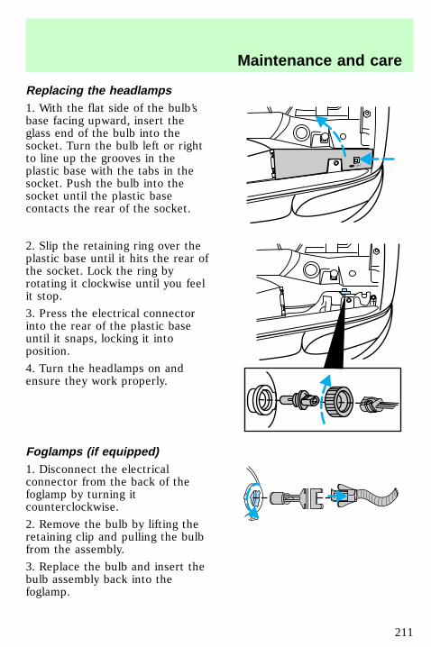
Replacing the headlamps1. With the flat side of the bulb’sbase facing upward, insert theglass end of the bulb into thesocket. Turn the bulb left or rightto line up the grooves in theplastic base with the tabs in thesocket. Push the bulb into thesocket until the plastic basecontacts the rear of the socket.
2. Slip the retaining ring over theplastic base until it hits the rear ofthe socket. Lock the ring byrotating it clockwise until you feelit stop.
3. Press the electrical connectorinto the rear of the plastic baseuntil it snaps, locking it intoposition.
4. Turn the headlamps on andensure they work properly.
Foglamps (if equipped)1. Disconnect the electricalconnector from the back of thefoglamp by turning itcounterclockwise.
2. Remove the bulb by lifting theretaining clip and pulling the bulbfrom the assembly.
3. Replace the bulb and insert thebulb assembly back into thefoglamp.
LIFT
uno_foglamps
Maintenance and care
211
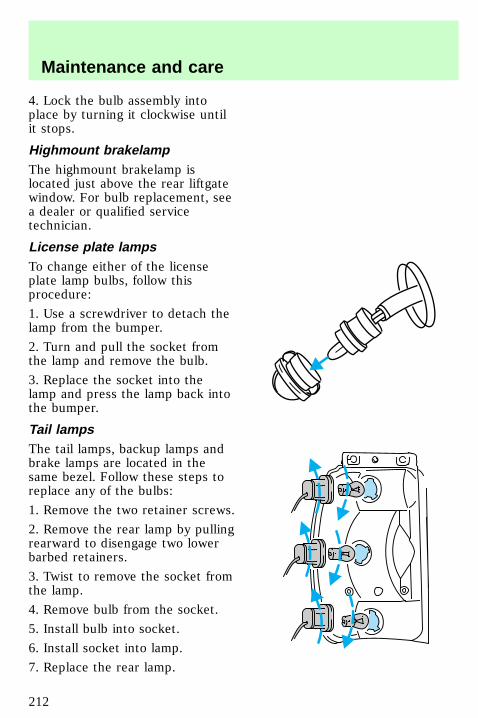
4. Lock the bulb assembly intoplace by turning it clockwise untilit stops.
Highmount brakelampThe highmount brakelamp islocated just above the rear liftgatewindow. For bulb replacement, seea dealer or qualified servicetechnician.
License plate lampsTo change either of the licenseplate lamp bulbs, follow thisprocedure:
1. Use a screwdriver to detach thelamp from the bumper.
2. Turn and pull the socket fromthe lamp and remove the bulb.
3. Replace the socket into thelamp and press the lamp back intothe bumper.
Tail lampsThe tail lamps, backup lamps andbrake lamps are located in thesame bezel. Follow these steps toreplace any of the bulbs:
1. Remove the two retainer screws.
2. Remove the rear lamp by pullingrearward to disengage two lowerbarbed retainers.
3. Twist to remove the socket fromthe lamp.
4. Remove bulb from the socket.
5. Install bulb into socket.
6. Install socket into lamp.
7. Replace the rear lamp.
uno_highmount
uno_license_plate
uno_tail_lamps
uno_interior_bulbs
Maintenance and care
212
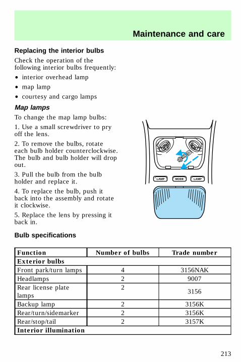
Replacing the interior bulbsCheck the operation of thefollowing interior bulbs frequently:
• interior overhead lamp
• map lamp
• courtesy and cargo lamps
Map lampsTo change the map lamp bulbs:
1. Use a small screwdriver to pryoff the lens.
2. To remove the bulbs, rotateeach bulb holder counterclockwise.The bulb and bulb holder will dropout.
3. Pull the bulb from the bulbholder and replace it.
4. To replace the bulb, push itback into the assembly and rotateit clockwise.
5. Replace the lens by pressing itback in.
Bulb specifications
Function Number of bulbs Trade number
Exterior bulbs
Front park/turn lamps 4 3156NAKHeadlamps 2 9007Rear license platelamps
23156
Backup lamp 2 3156KRear/turn/sidemarker 2 3156KRear/stop/tail 2 3157KInterior illumination
LAMP LAMPMODE
uno_maplamps
uno_bulb_spec_chart
Maintenance and care
213
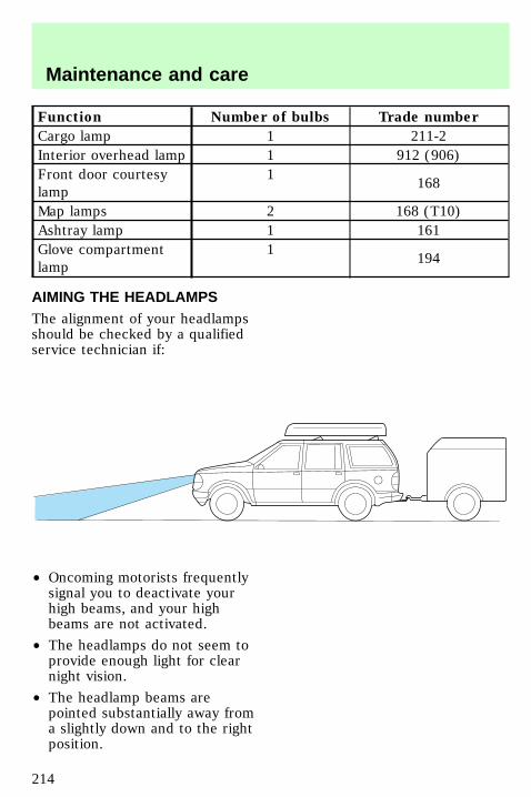
Function Number of bulbs Trade number
Cargo lamp 1 211-2Interior overhead lamp 1 912 (906)Front door courtesylamp
1168
Map lamps 2 168 (T10)Ashtray lamp 1 161Glove compartmentlamp
1194
AIMING THE HEADLAMPSThe alignment of your headlampsshould be checked by a qualifiedservice technician if:
• Oncoming motorists frequentlysignal you to deactivate yourhigh beams, and your highbeams are not activated.
• The headlamps do not seem toprovide enough light for clearnight vision.
• The headlamp beams arepointed substantially away froma slightly down and to the rightposition.
uno_aiming_headlamps
com_cleaning_caring.01
Maintenance and care
214
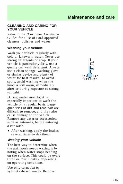
CLEANING AND CARING FORYOUR VEHICLERefer to the “Customer AssistanceGuide” for a list of Ford-approvedcleaners, polishes and waxes.
Washing your vehicleWash your vehicle regularly withcold or lukewarm water. Never usestrong detergents or soap. If yourvehicle is particularly dirty, use aquality car wash detergent. Alwaysuse a clean sponge, washing gloveor similar device and plenty ofwater for best results. To avoidspots, avoid washing when thehood is still warm, immediatelyafter or during exposure to strongsunlight.
During winter months, it isespecially important to wash thevehicle on a regular basis. Largequantities of dirt and road salt aredifficult to remove, and they alsocause damage to the vehicle.Remove any exterior accessories,such as antennas, before enteringa car wash.
• After washing, apply the brakesseveral times to dry them.
Waxing your vehicleThe best way to determine whenthe paintwork needs waxing is bynoting when water stops beadingon the surface. This could be everythree or four months, dependingon operating conditions.
Use only carnauba orsynthetic-based waxes. Remove
com_washing_vehicle.01
com_waxing_vehicle.01
Maintenance and care
215

any bugs and tar before waxingvehicle. Use cleaning fluid oralcohol with a clean cloth toremove. Use tar remover toremove any tar spots.
Repairing paint chipsMinor scratches or paint damagefrom road debris may be repairedwith touch-up paint, paint repairfoil or aerosol paint spray from theFord accessory line. Observe theapplication instructions on theproducts.
Remove particles such as birddroppings, tree sap, insectremains, tar spots, road salt andindustrial fallout immediately.
Cleaning the wheelsWash the wheels with the samedetergent you use to clean thebody of your vehicle. Do not useacid-based wheel cleaners, steelwool, fuel or strong detergents.Never use abrasives that willdamage the finish of special wheelsurfaces. Use a tar remover toremove grease and tar.
Cleaning the engineEngines are more efficient whenthey are clean because grease anddirt buildup act as insulators andkeep the engine warmer thannormal. Follow these guidelines toclean your engine:
• Take care when using a powerwasher to clean the engine. The
com_repairing_chips
uno_wheels_cleaning
com_engine_cleaning.01
Maintenance and care
216
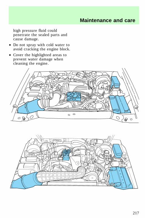
high pressure fluid couldpenetrate the sealed parts andcause damage.
• Do not spray with cold water toavoid cracking the engine block.
• Cover the highlighted areas toprevent water damage whencleaning the engine.
Maintenance and care
217
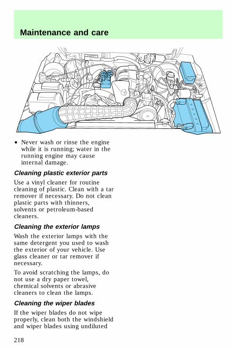
• Never wash or rinse the enginewhile it is running; water in therunning engine may causeinternal damage.
Cleaning plastic exterior partsUse a vinyl cleaner for routinecleaning of plastic. Clean with a tarremover if necessary. Do not cleanplastic parts with thinners,solvents or petroleum-basedcleaners.
Cleaning the exterior lampsWash the exterior lamps with thesame detergent you used to washthe exterior of your vehicle. Useglass cleaner or tar remover ifnecessary.
To avoid scratching the lamps, donot use a dry paper towel,chemical solvents or abrasivecleaners to clean the lamps.
Cleaning the wiper bladesIf the wiper blades do not wipeproperly, clean both the windshieldand wiper blades using undiluted
com_plastic_exterior.01
uno_exterior_lamps
uno_wiper_cleaning
Maintenance and care
218
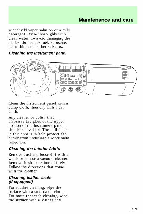
windshield wiper solution or a milddetergent. Rinse thoroughly withclean water. To avoid damaging theblades, do not use fuel, kerosene,paint thinner or other solvents.
Cleaning the instrument panel
Clean the instrument panel with adamp cloth, then dry with a drycloth.
Any cleaner or polish thatincreases the gloss of the upperportion of the instrument panelshould be avoided. The dull finishin this area is to help protect thedriver from undesirable windshieldreflection.
Cleaning the interior fabricRemove dust and loose dirt with awhisk broom or a vacuum cleaner.Remove fresh spots immediately.Follow the directions that comewith the cleaner.
Cleaning leather seats(if equipped)For routine cleaning, wipe thesurface with a soft, damp cloth.For more thorough cleaning, wipethe surface with a leather and
0
P R N D 2 1
RPMx1000
1
2
34
5 6
H
C
E
F
RSM
SETACC
COASTOFF
ONOFF
SRS
HI
LO OFF
*A/C
*MAXA/C
REW1
FF2
SIDE 1-23
FM 1 ST
VOL – PUSH ON
AMFM BASS TREB BAL FADE
AUTOSET
CLK
SEEK
TUNEDISCS
SCAN
4
DOLBY SYSTEM
EJ TAPE CD
COMP5
SHUFFLE6
PUSH
0
20
10
30
4050 60 70
80
90
110
120
0 0 0 0 0 0
o o o o
km/h
10020
40
6080 100 120
140
160
180
uno_instru-panel_cleaning
com_int_fabric_cleaning.01
com_leather_seats_cleaning.01
Maintenance and care
219
vinyl cleaner or a mild soap.
Cleaning and maintaining thesafety beltsClean the safety belts with a mildsoap solution recommended forcleaning upholstery or carpets. Donot bleach or dye the belts,because these actions may weakenthe belt webbing.
All safety belt assemblies,including retractors, buckles, frontseat belt buckle support assemblies(slide bar) (if equipped), shoulderbelt height adjusters (if equipped),child safety seat tether bracketassemblies (if equipped) andattaching hardware should beinspected after any collision. Fordrecommends that all safety beltassemblies used in vehiclesinvolved in a collision be replaced.However, if the collision was minorand a qualified technician findsthat the belts do not show damageand continue to operate properly,they do not need to be replaced.Safety belt assemblies not in useduring a collision should also beinspected and replaced if eitherdamage or improper operation isnoted.
Cleaning the built-in child seat(if equipped)Clean the built-in child seat withmild soap and water. Do not usehousehold cleaning productsbecause they may weaken thesafety belt webbing or damage thevinyl parts of the seat.
com_safety_belts_cleaning.01
com_child-seat_cleaning.01
Maintenance and care
220
The child seat liner is removableand may be machine-washed andair dried.
Maintenance and care
221
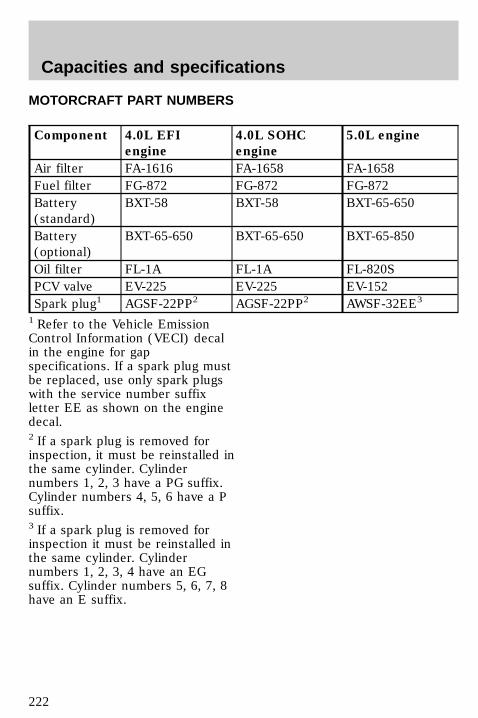
MOTORCRAFT PART NUMBERS
Component 4.0L EFI
engine
4.0L SOHC
engine
5.0L engine
Air filter FA-1616 FA-1658 FA-1658Fuel filter FG-872 FG-872 FG-872Battery(standard)
BXT-58 BXT-58 BXT-65-650
Battery(optional)
BXT-65-650 BXT-65-650 BXT-65-850
Oil filter FL-1A FL-1A FL-820SPCV valve EV-225 EV-225 EV-152Spark plug1 AGSF-22PP2 AGSF-22PP2 AWSF-32EE3
1 Refer to the Vehicle EmissionControl Information (VECI) decalin the engine for gapspecifications. If a spark plug mustbe replaced, use only spark plugswith the service number suffixletter EE as shown on the enginedecal.2 If a spark plug is removed forinspection, it must be reinstalled inthe same cylinder. Cylindernumbers 1, 2, 3 have a PG suffix.Cylinder numbers 4, 5, 6 have a Psuffix.3 If a spark plug is removed forinspection it must be reinstalled inthe same cylinder. Cylindernumbers 1, 2, 3, 4 have an EGsuffix. Cylinder numbers 5, 6, 7, 8have an E suffix.
com_explorer-part-numbers
Capacities and specifications
222
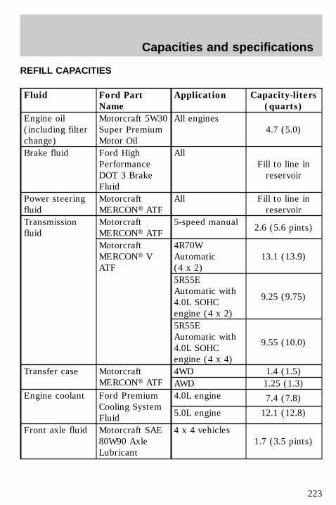
REFILL CAPACITIES
Fluid Ford Part
Name
Application Capacity-liters
(quarts)
Engine oil(including filterchange)
Motorcraft 5W30Super PremiumMotor Oil
All engines4.7 (5.0)
Brake fluid Ford HighPerformanceDOT 3 BrakeFluid
AllFill to line inreservoir
Power steeringfluid
MotorcraftMERCONt ATF
All Fill to line inreservoir
Transmissionfluid
MotorcraftMERCONt ATF
5-speed manual2.6 (5.6 pints)
MotorcraftMERCONt VATF
4R70WAutomatic(4 x 2)
13.1 (13.9)
5R55EAutomatic with4.0L SOHCengine (4 x 2)
9.25 (9.75)
5R55EAutomatic with4.0L SOHCengine (4 x 4)
9.55 (10.0)
Transfer case MotorcraftMERCONt ATF
4WD 1.4 (1.5)AWD 1.25 (1.3)
Engine coolant Ford PremiumCooling SystemFluid
4.0L engine 7.4 (7.8)
5.0L engine 12.1 (12.8)
Front axle fluid Motorcraft SAE80W90 AxleLubricant
4 x 4 vehicles1.7 (3.5 pints)
com_explorer-refills
Capacities and specifications
223
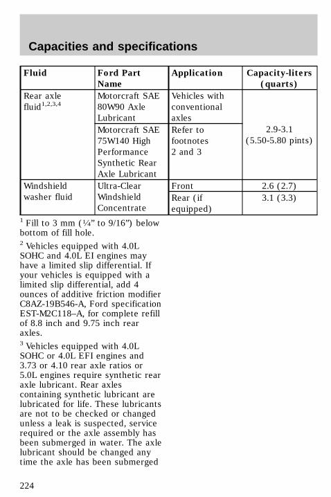
Fluid Ford Part
Name
Application Capacity-liters
(quarts)
Rear axlefluid1,2,3,4
Motorcraft SAE80W90 AxleLubricant
Vehicles withconventionalaxles
2.9-3.1(5.50-5.80 pints)
Motorcraft SAE75W140 HighPerformanceSynthetic RearAxle Lubricant
Refer tofootnotes2 and 3
Windshieldwasher fluid
Ultra-ClearWindshieldConcentrate
Front 2.6 (2.7)Rear (ifequipped)
3.1 (3.3)
1 Fill to 3 mm (1⁄4” to 9/16”) belowbottom of fill hole.2 Vehicles equipped with 4.0LSOHC and 4.0L EI engines mayhave a limited slip differential. Ifyour vehicles is equipped with alimited slip differential, add 4ounces of additive friction modifierC8AZ-19B546-A, Ford specificationEST-M2C118–A, for complete refillof 8.8 inch and 9.75 inch rearaxles.3 Vehicles equipped with 4.0LSOHC or 4.0L EFI engines and3.73 or 4.10 rear axle ratios or5.0L engines require synthetic rearaxle lubricant. Rear axlescontaining synthetic lubricant arelubricated for life. These lubricantsare not to be checked or changedunless a leak is suspected, servicerequired or the axle assembly hasbeen submerged in water. The axlelubricant should be changed anytime the axle has been submerged
Capacities and specifications
224
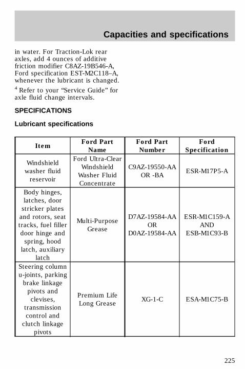
in water. For Traction-Lok rearaxles, add 4 ounces of additivefriction modifier C8AZ-19B546-A,Ford specification EST-M2C118–A,whenever the lubricant is changed.4 Refer to your “Service Guide” foraxle fluid change intervals.
SPECIFICATIONS
Lubricant specifications
ItemFord Part
Name
Ford Part
Number
Ford
Specification
Windshieldwasher fluidreservoir
Ford Ultra-ClearWindshieldWasher FluidConcentrate
C9AZ-19550-AAOR -BA
ESR-M17P5-A
Body hinges,latches, doorstricker platesand rotors, seattracks, fuel fillerdoor hinge andspring, hoodlatch, auxiliary
latch
Multi-PurposeGrease
D7AZ-19584-AAOR
D0AZ-19584-AA
ESR-M1C159-AAND
ESB-M1C93-B
Steering columnu-joints, parkingbrake linkagepivots andclevises,
transmissioncontrol andclutch linkage
pivots
Premium LifeLong Grease
XG-1-C ESA-M1C75-B
uno_special_lube_specs
uno_lubricants
Capacities and specifications
225
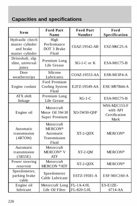
ItemFord Part
Name
Ford Part
Number
Ford
Specification
Hydraulic clutchmaster cylinder
and brakemaster cylinder
HighPerfromanceDOT 3 Brake
Fluid
C6AZ-19542-AB ESZ-M6C25-A
Driveshaft, slipsline, universal
joints
Premium LongLife Grease
XG-1-C or K ESA-M1C75-B
Doorweatherstrips
SiliconeLubricants
COAZ-19553-AA ESR-M13P4-A
Engine coolantFord PremiumCooling System
FluidE2FZ-19549-AA ESE-M97B44-A
ATX shiftlinkage
Premium LongLife Grease
XG-1-C ESA-M1C75-B
Engine oilMotorcraft
Motor Oil 5W-30Super Premium
XO-5W30-QSP
WSS-M2C153-Fwith API
CertificationMark
Automatictransmission(4R7OW)
MotorcraftMERCONtAutomatic
TransmissionFluid
XT-2-QDX MERCONt
Automatictransmission(5R55E)
MotorcraftMERCONt V
ATFXT-2-QM MERCONt
Power steeringreservoir
MotorcraftMERCON tATF
XT-2-QDX MERCONt
Speedometer,parking brake
cable
SpeedometerCable Lubricant
E6TZ-19581-A ESF-M1C160-A
Engine oillubricant
Motorcraft LongLife Oil Filter
FL-1A-4.0LFL-820-5.0L
ES-E1ZE-6714-AA
Capacities and specifications
226
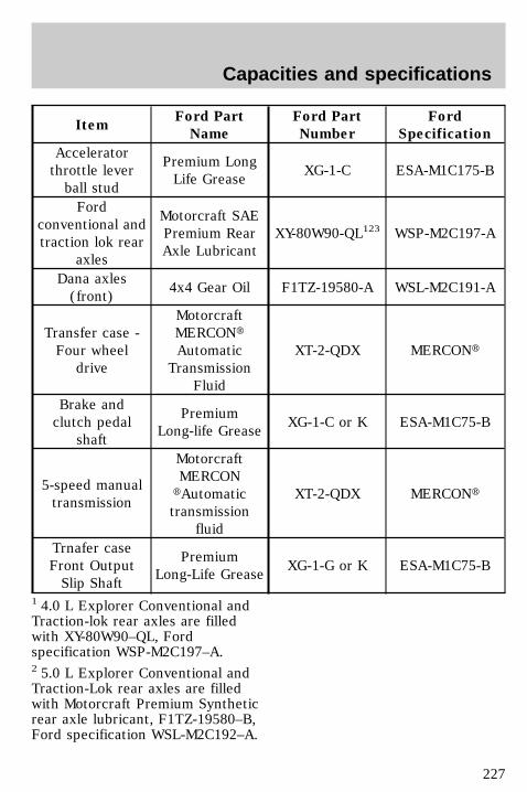
ItemFord Part
Name
Ford Part
Number
Ford
Specification
Acceleratorthrottle leverball stud
Premium LongLife Grease
XG-1-C ESA-M1C175-B
Fordconventional andtraction lok rear
axles
Motorcraft SAEPremium RearAxle Lubricant
XY-80W90-QL123 WSP-M2C197-A
Dana axles(front)
4x4 Gear Oil F1TZ-19580-A WSL-M2C191-A
Transfer case -Four wheel
drive
MotorcraftMERCONtAutomatic
TransmissionFluid
XT-2-QDX MERCONt
Brake andclutch pedal
shaft
PremiumLong-life Grease
XG-1-C or K ESA-M1C75-B
5-speed manualtransmission
MotorcraftMERCON
tAutomatictransmission
fluid
XT-2-QDX MERCONt
Trnafer caseFront OutputSlip Shaft
PremiumLong-Life Grease
XG-1-G or K ESA-M1C75-B
1 4.0 L Explorer Conventional andTraction-lok rear axles are filledwith XY-80W90–QL, Fordspecification WSP-M2C197–A.2 5.0 L Explorer Conventional andTraction-Lok rear axles are filledwith Motorcraft Premium Syntheticrear axle lubricant, F1TZ-19580–B,Ford specification WSL-M2C192–A.
Capacities and specifications
227
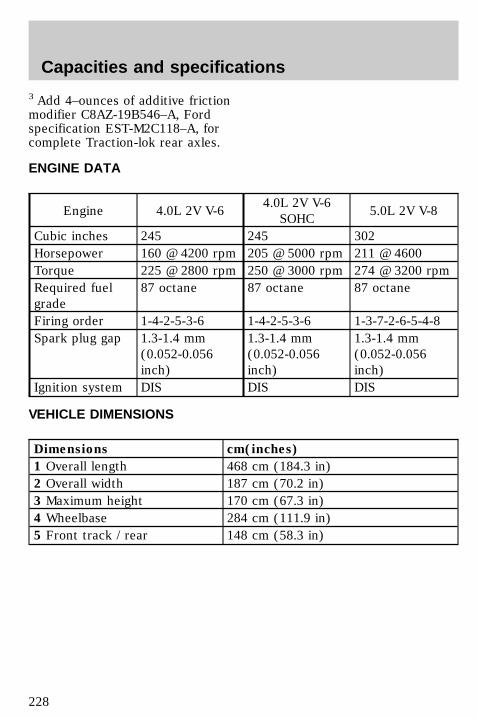
3 Add 4–ounces of additive frictionmodifier C8AZ-19B546–A, Fordspecification EST-M2C118–A, forcomplete Traction-lok rear axles.
ENGINE DATA
Engine 4.0L 2V V-64.0L 2V V-6
SOHC5.0L 2V V-8
Cubic inches 245 245 302Horsepower 160 @ 4200 rpm 205 @ 5000 rpm 211 @ 4600Torque 225 @ 2800 rpm 250 @ 3000 rpm 274 @ 3200 rpmRequired fuelgrade
87 octane 87 octane 87 octane
Firing order 1-4-2-5-3-6 1-4-2-5-3-6 1-3-7-2-6-5-4-8Spark plug gap 1.3-1.4 mm
(0.052-0.056inch)
1.3-1.4 mm(0.052-0.056inch)
1.3-1.4 mm(0.052-0.056inch)
Ignition system DIS DIS DIS
VEHICLE DIMENSIONS
Dimensions cm(inches)
1 Overall length 468 cm (184.3 in)2 Overall width 187 cm (70.2 in)3 Maximum height 170 cm (67.3 in)4 Wheelbase 284 cm (111.9 in)5 Front track / rear 148 cm (58.3 in)
uno_engine_data
uno_vehicle_dimensions
Capacities and specifications
228
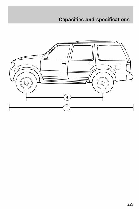
4
1
Capacities and specifications
229

IDENTIFYING YOUR VEHICLE
Vehicle identification tagThe vehicle identification tag islocated on the front panel of theengine compartment. This tagbears technical information onyour vehicle and identifies variouscomponents.
Vehicle identification numberThe vehicle identification number(VIN) is attached to a tag and islocated on the front driver’s side ofthe instrument panel. The VIN tagmay be seen by looking throughthe windshield from the outside ofthe vehicle.
3
5
2
uno_id_plate
uno_vin_number
uno_engine_block_number
Capacities and specifications
230
Engine numberThe engine number is stamped onthe engine block.
Capacities and specifications
231
REPORTING SAFETY DEFECTS(U.S. ONLY)If you believe that your vehicle hasa defect that could cause a crash,or could cause injury or death, youshould immediately inform theNational Highway Traffic SafetyAdministration (NHTSA) inaddition to Ford Motor Company.
If NHTSA receives similarcomplaints, it may open aninvestigation, and if it finds that asafety defect exists in a group ofvehicles, it may order a recall andremedy campaign. However,NHTSA cannot become involved inindividual problems between you,your dealer or Ford MotorCompany.
To contact NHTSA, you may eithercall the Auto Safety Hotlinetoll-free at 1–800–424–9393(202–366–0123 in the WashingtonD.C. area) or write to:
NHTSA
U.S. Department of Transportation
400 Seventh Street
Washington D.C. 20590
You can also obtain otherinformation about motor vehiclesafety from the Hotline.
com_reporting_defects.01
Reporting safety defects
232
Air bag supplemental restraintsystemand child safety seats ..............90description ................................89disposal ......................................94indicator light ...........................93passenger air bag .....................91
Air cleaner filter .......................192replacing ..................................193
Air conditioningmanual heating and airconditioningsystem ...................28,29,30,31,32
Air suspension ...........................119All wheel drive (AWD) .............134Anti-theft system ........................65arming the system ....................66disarming a triggered system ..68disarming an untriggeredsystem .......................................68warning light .............................67
Autolamp system (seeHeadlamps) .................................49Automatic dimming mirror ...47,48Battery .......................................188battery saver ...........................192servicing ....................188,189,190
Brakesadjustment ..............................117anti-lock ...................................117fluid, checking and adding ....177parking ....................................118
Break-in period .............................2Built-in child seat .......102,107,108Bulbs,replacing ........208,210,211,212,213specifications ..........................213
Capacities for refilling fluids ....225Cargo area shade ........................64Childproof locks ..........................55Cleaning your vehicle ...............215built-in child seat ...................220
engine compartment ..............216fabric ........................................219instrument panel ....................219plastic parts ............................218safety belts ..............................220tail lamps .................................218washing ....................................215waxing .....................................215wheels ......................................216
Climate control system ..............28automatic temperaturecontrol ...................32,33,34,35,36defrosting .............................59,60
Clutchfluid ..........................................177
Compass, electronic ....................50calibration .................................51set zone adjustment .................51
Console, description ..............58,61Control trac 4WD system .........128Controls ..................................58,59Coolant (see Engine coolant)proper solution .......................181
Daytime running light system ...26Differential fluid ........................187Driveline universal joint andslip yoke .............................176,187Driving under specialconditions ..................................130high water ...............................131slippery roads ..................132,133towing a trailer .......................144
Emission control system ..........206Engine .................................228,231service points ............170,171,172
Engine block heater .................116Engine coolantchecking and adding .......180,183checking hoses .......................184disposal ....................................182refill capacities ........................182
Index
233
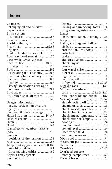
Engine oilchanging oil and oil filter .......175specifications ..........................173
Entry systemillumination ...............................66
Exhaust fumes ..........................112Flashing the lights ......................45Floor mats ..............................62,63Foglamps .....................................27Ford Extended Service Plan ....129Four way head restraints ...........78Four-Wheel Drive vehiclescontrol trac ........................38,128driving off road .......................130
Fuel ............................................202calculating fuel economy .......206improving fuel economy ........146octane rating ...........................204quality ......................................205safety information relating toautomotive fuels .....................202
Fuel gauge ...................................15Fuel pump shut-off switch .......147Fuses ..........................................148Gauges, Mechanicalengine coolant temperaturegauge .........................................13engine oil pressure gauge ........13
Hazard flashers ....................44,147Head restraints ...........................78Hitch ..........................................144Hood ..........................................169Identification Number, Vehicle(VIN) ..........................................230Ignitionpositions of the ignition ...........39
Jack ..............................................63Jump-starting your vehicle 160,162attaching cables ......................161disconnecting cables ..............162
Keyless entry systemautolock .....................................76
keypad .......................................74locking and unlocking doors ....74programming entry code .........75
Lampsinstrument panel, dimming .....26
Liftgate ........................................57Lights, warning and indicatorair bag ........................................11anti-lock brakes (ABS) ............11anti-theft .....................................9brake ..........................................11charging system ........................10check engine ...............................9door ajar ....................................10four-wheel drive ..........................9fuel reset ...................................10high beam .................................11overdrive off ................................8safety belt .......................11,87,88
Luggage rack .............................146Manual transmissiondriving .......................121,125,127fluid, checking and adding ....187
Message center ..16,17,18,19,20,52air ride switch off .....................21change oil soon .........................21check air ride system ...............20check charging system .............22check engine temperature .......22check exterior lamps ................22door ajar ....................................24low fuel level .............................24low oil level ...............................24low washer fluid .......................24warning messages .....................20
Moon roof ....................................54Motorcraft parts ........................222Odometer .....................................14Overdrive ................................45,46Overhead consolestorage compartment ...............52
Parking brake ..............................28
Index
234
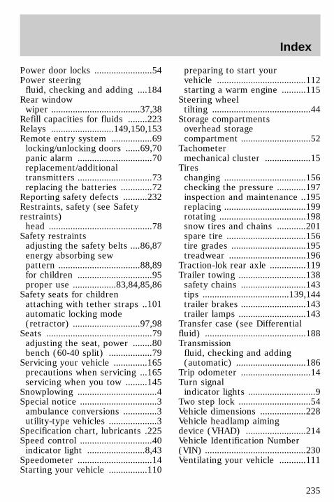
Power door locks ........................54Power steeringfluid, checking and adding ....184
Rear windowwiper .....................................37,38
Refill capacities for fluids ........223Relays ..........................149,150,153Remote entry system .................69locking/unlocking doors ......69,70panic alarm ...............................70replacement/additionaltransmitters ...............................73replacing the batteries .............72
Reporting safety defects ..........232Restraints, safety (see Safetyrestraints)head ...........................................78
Safety restraintsadjusting the safety belts ....86,87energy absorbing sewpattern ..................................88,89for children ...............................95proper use ..................83,84,85,86
Safety seats for childrenattaching with tether straps ..101automatic locking mode(retractor) ............................97,98
Seats ............................................79adjusting the seat, power ........80bench (60-40 split) ..................79
Servicing your vehicle ..............165precautions when servicing ...165servicing when you tow .........145
Snowplowing .................................4Special notice ................................3ambulance conversions ..............3utility-type vehicles ....................3
Specification chart, lubricants .225Speed control ..............................40indicator light ........................8,43
Speedometer ...............................14Starting your vehicle ................110
preparing to start yourvehicle .....................................112starting a warm engine ..........115
Steering wheeltilting .........................................44
Storage compartmentsoverhead storagecompartment .............................52
Tachometermechanical cluster ...................15
Tireschanging ..................................156checking the pressure ............197inspection and maintenance ..195replacing ..................................199rotating ....................................198snow tires and chains ............201spare tire .................................156tire grades ...............................195treadwear ................................196
Traction-lok rear axle ...............119Trailer towing ............................138safety chains ...........................143tips ....................................139,144trailer brakes ...........................143trailer lamps ............................143
Transfer case (see Differentialfluid) ..........................................188Transmissionfluid, checking and adding(automatic) .............................186
Trip odometer .............................14Turn signalindicator lights ............................9
Two step lock ..............................54Vehicle dimensions ...................228Vehicle headlamp aimingdevice (VHAD) .........................214Vehicle Identification Number(VIN) ..........................................230Ventilating your vehicle ...........111
Index
235
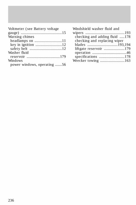
Voltmeter (see Battery voltagegauge) ..........................................15Warning chimesheadlamps on ............................11key in ignition ...........................12safety belt .................................12
Washer fluidreservoir ..................................179
Windowspower windows, operating .......56
Windshield washer fluid andwipers ........................................193checking and adding fluid .....178checking and replacing wiperblades ...............................193,194liftgate reservoir .....................179operation ...................................46specifications ..........................178
Wrecker towing .........................163
236
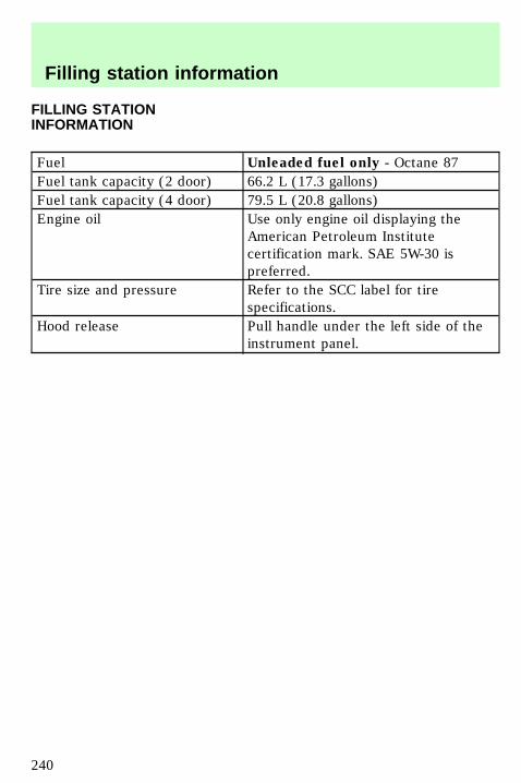
FILLING STATIONINFORMATION
Fuel Unleaded fuel only - Octane 87Fuel tank capacity (2 door) 66.2 L (17.3 gallons)Fuel tank capacity (4 door) 79.5 L (20.8 gallons)Engine oil Use only engine oil displaying the
American Petroleum Institutecertification mark. SAE 5W-30 ispreferred.
Tire size and pressure Refer to the SCC label for tirespecifications.
Hood release Pull handle under the left side of theinstrument panel.
uno_filling_station
Filling station information
240


![IntroduCtIon - Berghahn Books · upper Gambia River (Bathily 1989; Manchuelle 1997). ‘The Serawoollies [Soninke]’, wrote British explorer Mungo Park (1816: 62), the first European](https://img.pdfslide.us/doc/110x75/5e82ddd548cd4562ee22d937/introduction-berghahn-books-upper-gambia-river-bathily-1989-manchuelle-1997.jpg)


![[MS-HTML5]: Microsoft Edge / Internet Explorer …MS-HTML5].pdfMicrosoft Edge / Internet Explorer HTML5 ... Microsoft Edge / Internet Explorer HTML5 ... Microsoft Edge / Internet Explorer](https://img.pdfslide.us/doc/110x75/5ad35ecf7f8b9aff738de6d3/ms-html5-microsoft-edge-internet-explorer-ms-html5pdfmicrosoft-edge-.jpg)