Embed Size (px)
DESCRIPTION
turbopump
Citation preview
NASA Technical Paper 1443.
NASA ':-I TP 1443 1 c.1 '
i
for Liquid-Oxygen Turbopumps
Gordon P. Allen
APRIL 1979
NASA 1 ' I
! TECH LIBRARY KAFB, NM
NASA Technical Paper 1443
Comparison of Analysis and Experiment for Self-Acting Seals for Liquid-Oxygen Turbopumps
Gordon P. Allen Lewis Research Center Cleveland, Ohio
National Aeronautics and Space Administration
Scientific and Technical Information Office
1979
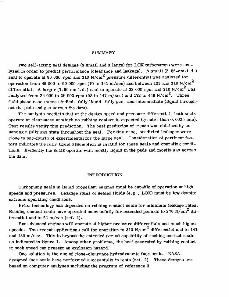
SUMMARY
Two self-acting seal designs (a small and a large) for LOX turbopumps were ana- lyzed in order to predict performance (clearance and leakage). A small (2.86-cm-i. d. ) seal to operate at 90 000 rpm and 310 N/cm 2 pressure differential was analyzed for operation from 45 000 to 90 000 rpm (70 to 141 m/sec) and between 103 and 310 N/cm 2 differential. A larger (7.66 cm i. d.) seal to operate at 32 000 rpm and 310 N/cm 2 was analyzed from 24 000 to 36 000 rpm (98 to 147 m/sec) and 172 to 448 N/cm2. Three fluid phase cases were studied: fully liquid, fully gas, and intermediate (liquid through- out the pads and gas across the dam).
The analysis predicts that at the design speed and pressure differential, both seals operate at clearances at which no rubbing contact is expected (greater than 0.0025 mm). Test results verify this prediction. The best prediction of trends was obtained by as- suming a fully gas state throughout the seal. For this case, predicted leakages were close to one-fourth of experimental for the large seal. Consideration of pertinent fac- tors indicates the fully liquid assumption is invalid for these seals and operating condi- tions. Evidently the seals operate with mostly liquid in the pads and mostly gas across the dam.
INTRODUCTION
Turbopump seals in liquid propellant engines must be capable of operation at h igh speeds and pressures. Leakage rates of sealed fluids (e. g., LOX) must be low despite extreme operating conditions.
Prior technology has depended on rubbing contact seals for minimum leakage rates. Rubbing contact seals have operated successfully for extended periods to 276 N/cm 2 dif- ferential and to 52 m/sec (ref. 1).
But advanced engines will operate at higher pressure differentials and much higher speeds. Two recent applications call for operation to 310 N/cm 2 differential and to 141 and 130 m/sec. This is beyond the entended period capability of rubbing contact seals as indicated in figure 1. Among other problems, the heat generated by rubbing contact at such speed can present an explosion hazard.
One solution is the use of close-clearance hydrodynamic face seals. NASA- designed face seals have performed successfully in tests (ref. 2). These designs are based on computer analyses including the program of reference 3.

The objective of this study is (1) analytically predict seal performance (equilibrium clearance and leakage) and (2) to compare predicted performance with experimental per- formance. Self-acting radial face seals of two sizes (2.86 and 7.66 cm i. d.) were ana- lyzed. The smaller was studied over the ranges of 45 000 to 90 000 rpm (70 to 141 m/sec) and 103 to 310 N/cm pressure differential. The larger was studied over 24 000 to 36 000 rpm (98 to 147 m/sec) and 172 to 448 N/cm differential. The experi- mental data was obtained with LOX near the boiling point at the sealed pressure.
2 2
TEST SEALS
The seals studied here were designed and analyzed for performance at Lewis Re- search Center. Testing of the seals was done - under two contracts - by Rocketdyne Division of Rockwell International.
The SSME LOX turbopump seal system in which the larger of the two seals to be analyzed can be applied is shown in figure 2. Propellant (Ha) vapor is separated from oxidant (02) by a purge gas (He). The flow directions are indicated. The propellant is vented between two ring seals and also adjacent to a purge gas seal. The oxidant is vented adjacent to the other purge gas seal.
The small seal was intended for application in the space tug engine. A schematic is presented in figure 3. The test rig for this seal is described in reference 2. The con- figuration of and the test rigs for the two seals are similar.
Both seals are close-clearance hydrodynamic radial face seals with shrouded Rayleigh step bearing lift pads. The sealed fluid is at the outside diameter of both. The seal dams are adjacent to the inside diameter - inside the lift pads. Both are spring loaded and have piston ring secondary seals. From the standpoint of analysis, they are basically identical. The dimensions of interest in analysis are presented in table I. Both seals have a flow length (across the dam) of 0.13 cm; both have 10 lift pads with a recess arc to land arc ratio of 2 to 1.
OPERATING CONDITIONS ANALYZED
The small seal was designed to operate at speeds up to 90 000 rpm (141 m/sec) and pressure differentials up to 310 N/cm . Speeds of 45 000, 60 000, 75 000, and 90 000 rpm and differentials of 103, 172, 241, and 310 N/cm were selected as points for ana- lytical study.
The large seal was designed to operate to 32 000 rpm (130 m/sec) and 310 N/cm2 differential. However, overspeed (86 000 rpm) and overpressure (448 N/cm ) are in-
2 2
2
2
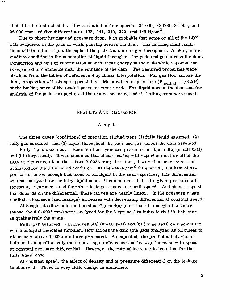
cluded in the test schedule. It was studied at four speeds: 24 000, 28 000, 32 000, and 36 000 rpm and five differentials: 172, 241, 310, 379, and 448 N/cm2.
Due to shear heating and pressure drop, it is probable that some o r all of the LOX will evaporate in the pads or while passing across the dam. The limiting fluid condi- tions will be either liquid throughout the pads and dam o r gas throughout. A likely inter- mediate condition is the assumption of liquid throughout the pads and gas across the dam. Conduction and heat of vaporization absorb shear energy in the pads while vaporization is expected to commence near the entrance of the dam. The required properties were obtained from the tables of reference 4 by linear interpolation. For gas flow across the dam, properties will change appreciably. Mean values of pressure (Psealed - 1/3 AP) at the boiling point of the sealed pressure were used. For liquid across the dam and for analysis of the pads, properties at the sealed pressure and its boiling point were used.
RESULTS AND DISCUSSION
Analysis
The three cases (conditions) of operation studied were (1) fully liquid assumed, (2) fully gas assumed, and (3) liquid throughout the pads and gas across the dam assumed.
Fully liquid assumed. - Results of analysis are presented in figure 4(a) (small seal) and (b) (large seal). It was assumed that shear heating wil l vaporize most o r all of the LOX at clearances less than about 0.0025 mm; therefore, lower clearances were not evaluated for the fully liquid condition. At the 448-N/cm differential, the heat of va- porization is low enough that most or all liquid in the seal vaporizes; this differential was not analyzed for the fully liquid case. It can be seen that, at a given pressure dif- ferential, clearance - and therefore leakage - increases with speed. And above a speed that depends on the differential, these curves are nearly linear. In the pressure range studied, clearance (and leakage) increases with decreasing differential at constant speed.
Although this discussion is based on figure 4(a) (small seal), enough clearances (above about 0.0025 mm) were analyzed for the large seal to indicate that its behavior is qualitatively the same.
Fully gas assumed. - In figures 5(a) (small seal) and (b) (large seal) only points for which analysis indicates turbulent flow across the dam (the pads analyzed as turbulent to clearances above 0.0025 mm) are presented. As expected, the predicted behavior of both seals is qualitatively the same. Again clearance and leakage increase with speed at constant pressure differential. However, the rate of increase is less than for the fully liquid case.
2
~"
At constant speed, the effect of density and of pressure differential on the leakage is observed. There is very little change in clearance.
3

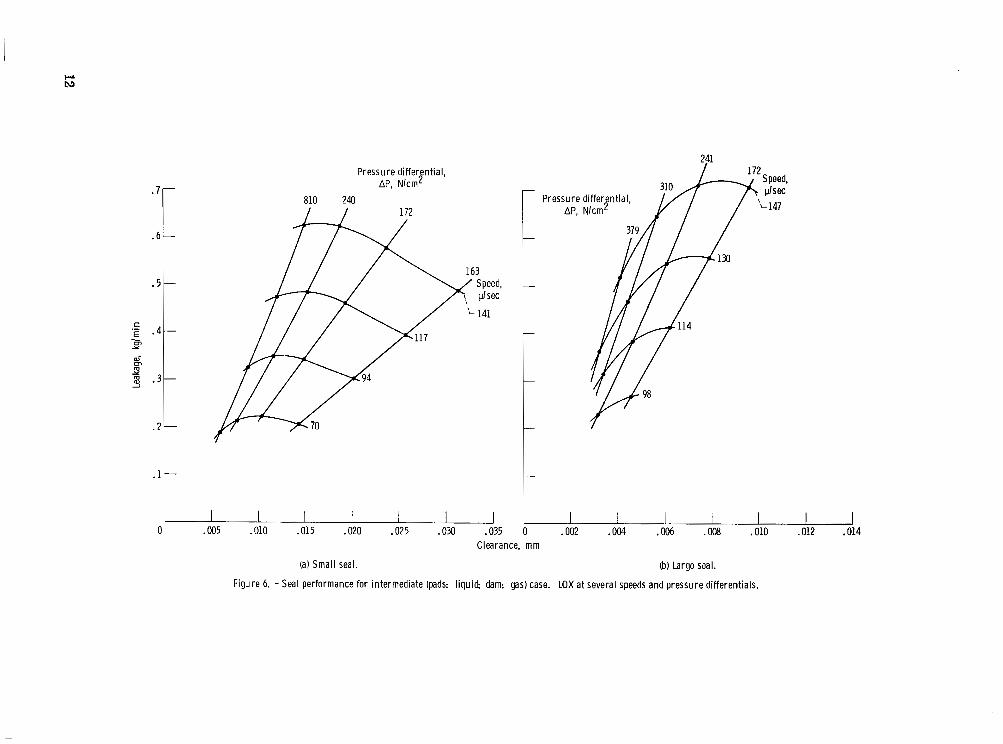
Intermediate (liquid in pads, gas in dam). - Results when turbulent flow across the dam is predicted are presented in figures 6(a) (small seal) and (b) (large seal). Again the 448 N/cm differential was not analyzed. As with the other two cases, there is an increase of clearance and leakage with speed at constant pressure differential.
2
However, for constant speed, the leakage reaches a maximum and decreases al- though clearance continues to increase as differential decreases.
Comparison of conditions. - A comparison of figures 4(a), 5(a), and 6(a) - for the small seal (the large seal is similar) - shows that clearance and leakage increase with increasing speed at constant pressure differential for all three cases although there is a more rapid increase for the fully liquid case. The other two cases (figs. 5(a) and 6(a)) show similar trends at constant differential.
For constant speed, the fully gas case differs from the other two. The fully liquid case curves show decreasing slopes - it can be anticipated that as pressure differential decreases, the leakage rate will eventually begin to decrease.
In table II, results for a selected portion of the ranges studied are presented for direct comparison. In the ranges of speed and pressure differential covered, the inter- mediate case (3 above) has the greatest clearance. Which condition has the least clear- ance depends on both speed and differential. As speed increases ( a t constant pressure differential) or as differential decreases at constant speed, the clearance of the all gas case increases relative to that of the all liquid case and becomes larger than the all liq- uid. It can also be seen that although the all gas case shows little effect of pressure dif- ferential on clearance, the intermediate case shows a decrease in clearance as pressure rises; and the single point at the 379 N/cm differential for the large seal at which com- 2
parison is possible shows that the intermediate case no longer has the greatest clear- ance. In table 11, the all liquid case shows the greatest leakage rates. However, con- sideration of clearance and leakage trends indicates that at low enough speed or high enough pressure differential, the all liquid rate will f a l l below that of one or both of the order cases. This is actually predicted for the large seal.
At the design speed (small: 141 m/sec; large: 130) and pressure differential (both: 310 N/cm ), analysis of the small seal indicates clearances of 0.0086 mm for the all liquid case, 0.0089 mm for the all gas condition and 0.015 mm for the intermediate con- ditions. For the large seal, clearances of less than 0.0025 mm (all liquid), 0.0064 mm (all gas) and 0.0056 mm (intermediate) are predicted at design speed and differential. Since the all liquid case probably does not occur at design operation, it can be assumed that contact will occur only during startup and shutdown. This is confirmed by test re- ports that generally indicate little o r no wear and no surface damage.
2
4

Comparison of Analysis and Experiment
The model used for gas flow across the dam does not consider rotational shear heating and rotationally induced turbulence. The model used for liquid in the pads ne- glects the presence of the side rails of the pad recesses. One obvious result for both models is prediction of a lower clearance.
In table lII, the experimental speeds, pressures, and leakages for several test runs are presented together with the analytical results.
For the small seal test point, the intermediate case analysis offers the best agree- ment with experiment. The all liquid analysis predicts f a r too high a leakage while the all gas prediction is too low.
For the large seal test points, the all gas predictions show excellent qualitative agreement being very close to the estimated leakage. However, even the shortcoming of the dam model appears insufficient to account for the difference between analysis and experiment. Obviously at least a large portion of this seal is operating in a fully liquid condition..
The fully liquid and intermediate cases show the shortcoming of the model used for analysis of liquid throughout the pads. As is apparent, the relative error increases as the predicted clearance decreases. From this consideration it appears that this seal is not operating in a fully liquid condition. At the largest predicted clearance (for fully liquid) leakage is about twice the experimental value even though the e r ror is still ap- preciable (clearance is under half the recess depth).
The largest predicted clearance for the intermediate condition has a leakage rate of half the estimated experimental value. Again (as for the small seal), this condition is the closest approximation to reality of the three.
CONCLUSIONS
Two LOX turbopump seal designs were analyzed over ranges of pressure differen- tial and speed involved in testing the designs. A comparison of analysis and experiment led to the following conclusions:
1. Prediction by analysis that the seals would operate without rubbing contact was confirmed by test results.
2. Both seals evidently operated with mostly liquid in the pads and mostly gas across the dam.
5
3. An excellent prediction of performance trends was obtained by assuming gas throughout the seals. However, the low predicted leakage rates showed this assumption to be incorrect.
Lewis Research Center, National Aeronautics and Space Administration,
Cleveland, Ohio, January 9, 1979, 506-16.
REFERENCES
1. Burcham, R. E. ; and Keller, R. B. J. ; eds. : Liquid Rocket Engine Turbopump Rotating-Shaft Seals. NASA SP-8121, 1978.
2. Burcham, R. E. ; and Boynton, J. L. : Small High-speed Self-Acting Shaft Seals for Liquid Rocket Engines. (RI/RD77-195, Rocketdyne; NASA Contract NAS3-17769. ) NASA CR-135167, 1977.
3. Zuk, J. ; and Smith, P. J. : Quasi-One-Dimensional Compressible Flow Across Face Seals and Narrow Slots. II: Computer program. NASA TN D-6787, 1972.
4. Roder, H. M. ; and Weber, L. A. ; eds. : ASRDI Oxygen Technology Survey. Vol. I: Thermophysical Properties. NASA SP-3071, 1972.
6

w c u W rl
m m o t - - Q ) w r l w o m ~ m ~ ~ c u c u m w o t - d d o ; W & & d r l ~ d r - :
m u 3 w m 4 - 3 cu . . . w m m 4 0 4 0 0 0 N L - ~
0 "
3 2 : 4 . . .
4 - m m w e 0 0 4 0 0 0 0 . . .
cu t- 4
V
c u m m m f - m 0 0 4 0 0 0 0 "
4 e cu
4 " : m w f -
rl . .
f - - 0 w e e a 0 0 4 0 0 0 0 "
o o m m c u y . . 0
+ c u m w w w 0 0 0 0 0 0
0 . . .
5 m
I
.f H
7
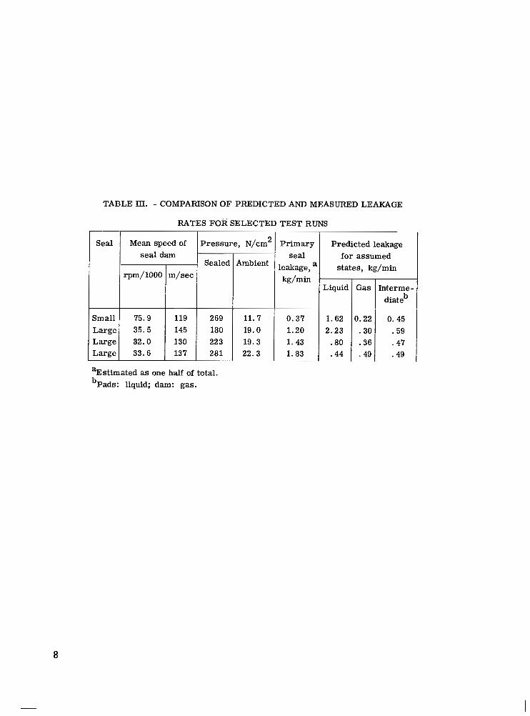
TABLE Et. - COMPARISON OF PFtEDICTED AND MEASURED LEAKAGE
RATES FOR SELECTED TEST RUNS
Seal T
Small Large Large Large
Mean speed of I Pressure, N/cm' seal dam
rpm/1000
75.9 35.5 32.0 33.6
4 Sealed m/sec
22 3
T Ambient
11.7 19.0 19.3 22.3
Primary seal
leakage, a
0.37 1.20 1.43 1.83
~~
Predicted leakage for assumed
states, kg/min
Liquid
1.62 2.23 .80 .44
Gas
3.22 .30 .36 .49
hterme- diate
0.45 .59 .47 .49
b _ _ _ _ ~
%Mimated as one half of total. bPads: liquid; dam: gas.
8
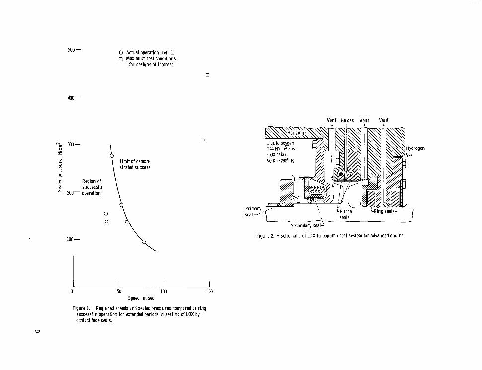
500 - 0 Actual operation (ref. 1) 0 Maximum test conditions
for designs of interest
300- 5 2
100-
Region of successful operation
Limit of demon- strated success
0 50 100 150 Speed, mlsec
Figure 1. - Required speeds and sealed pressures compared during successful operation for extended periods in sealing of LOX by contact face seals.
Vent Heaas Vent Vent
1 - Secondary seal
Figure 2. - Schematic of LOX turbopump seal system for advanced engine.

Figure 3. - NASA designed oxygen face seal with composite p is ton r ing for tug vehic le .
4.5- 103
4.0 -
3.5 -
3.0-
c .E 2.5- - Y m
a- - m Y
2 2.0-
1.5-
1.0-
.5 -
[' I I 1 1 1 0 .005 .010 .015 ,020 .025
Clearance, m m (a) Small seal.
Pressure differential,
Nlcm2 AP,
Speed,
'- 147
I I I I .0025 .0050 .0075 .0100
Ib) Large seal.
Figure 4. - Seal performance for fully l i qu id case. LOX at several speeds and pressure d i f ferent ia ls.
10

1. O r I
Pressure differential,
AP I .8 Nlcm2 t
Pressure differential,
N/cm2 AP.
I I d - 0 .005 .010 0 .002 .OW .OM .008
Clearance, mm
(a) Small seal. (b) Large seal.
Figure 5. - Seal performance for ful ly gas case. LOX at several speeds and pres- sure d i f ferent ia ls.
11
241
.7
. 6
.5
c ‘E . 4 - Y cn
W- cn 2 m . 3 m 2
.?
.1
l-
l-
c
l-
Pressure d i f ferent ia l , AP, N/cm2
810 240 I / 172
I, 0 .005 .010 .015 .020 .025 .030 .035
[ AP, N k m 2 379[ ’ Pressure differential,
L
c I/ I I
L
- I
-
0 .002 .OM .006 .OM . O l O .012 .014
1. Report No. I 2. Government Accession No. .
NASA TP-1443 4. Title and Subtitle
COMPARISON OF ANALYSIS AND EXPERIMENT FOR SELF- ACTING SEALS FOR LIQUID-OXYGEN TURBOPUMPS
7. Author(s1
Gordon P. Allen . . "~ - " " .
9. Performing Organization Name and Address . .
National Aeronautics and Space Administration Lewis Research Center Cleveland, Ohio 44135
12. Sponsoring Agency Name and Address
National Aeronautics and Space Administration Washington, D. C. 20546
15. Supplementary Notes - ..
. "
16. Abstract
3. Recipient's Catalog No
5. Report Date . .~~
A p r i l 1979 6. Performing Organization Code
8. Pe-forming Organization Report NO. ~-
E -9806 - 10. Work Unit No.
I_"" .
506- 16 11. fnntract or Grant No.
~~
13 Type of Report and Feriod Covered
Technical Paper -~
'4. Sponsoring Agency Code
- 1 Two LOX turbopump applications were analyzed over ranges of pressure differential and speed. Predictions were compared with test results. A small seal was analyzed up to 141 m/sec and 310 N/cm differential; a larger seal up to 147 m/sec and 448 N/cm . Tests confirmed analyti- cal predictions of operation without rubbing contact. The seals evidently operated with mostly liquid in the pads and mostly gas across the dam although the best prediction of trends was based on assuming gas throughout the entire seal.
2 2
~~ .
7. Key Words (Suggested by Author(s1 I
Face seal; Self-acting seal; Fluid flow; Leakage; Computer analysis
r
19. Security Classif. (of this report) 20. Security Classif. (of this page) 1 21. ~ 0 . ~ ; Pages
Unclassified 1- Unclassified -
* For sale by the National Technical Information Service, Spr inef le ld. Vlrglnla 22161
18. Distribution Statement
Unclassified - unlimited STAR Category 37
22. Price' I A02 - " .
NASA-Langley, 1979

National Aeronautics and SPECIAL FOURTH CLASS M A I L
Space Administration
Washington, D.C. 20546
Postage and Fees Paid
Space Administration NASA451
BOOK National Aeronautics and
Official Business
Penalty for Private Use, $300
4 1 1W,D, 033079 S00903DS DEPT OF THE A I R FORCE A F WEAPONS L A B O R A T O R Y ATTN: TECHNICAL LIBRARY {SUL) K I R T Z A N D AFB N M 87117
POSTMASTER: If Undeliverable (Section 1 5 8 Postal Manual) Do Not Return


