Embed Size (px)
Citation preview
Page 1 of 5 (c) 2011 Total Cost Involved Engineering, Inc. All Rights Reserved.
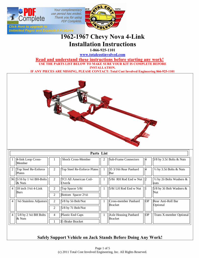
1962-1967 Chevy Nova 4-Link
Installation Instructions 1-866-925-1101
www.totalcostinvolved.com Read and understand these instructions before starting any work!
USE THE PARTS LIST BELOW TO MAKE SURE YOUR KIT IS COMPLETE BEFORE INSTALLATION.
IF ANY PIECES ARE MISSING, PLEASE CONTACT: Total Cost Involved Engineering 866-925-1101
Parts List
1 4-link Loop Cross-Member
1 Shock Cross-Member
2 Sub-Frame Connectors
4 3/8 by 3.5” Bolts & Nuts
2 Top Steel Re-Enforce Plates
2 Top Steel Re-Enforce Plates
1 35 3/16” Rear Panhard Bar
4 ½ by 3.5” Bolts & Nuts
36 5/16 by 1 ¼” BH-Bolts & Nuts
2 TCI All American Coil-Over’s
1 5/8” RH Rod End w Nut 2 ½ by 2” Bolts Washers & nuts
4 18 inch 1¼” 4-Link Bars
2 Top Spacer 5/8” 1 5/8” LH Rod End w Nut 1 5/8 by 3” Bolt Washers & Nut
2 Bottom Spacer 2½” 4 ¾” Stainless Adjustors
2 5/8 by 5” Bolt/Nut 1 Cross-member Panhard
Bracket
OP Rear Anti-Roll Bar Optional
2 5/8 by 7” Bolt/Nut
4 5/8 by 2 ¾” BH Bolts & Nuts
4 Plastic End Caps 1 Axle Housing Panhard Bracket
OP Trans X-member Optional
1 E-Brake Bracket
Safely Support Vehicle on Jack Stands Before Doing Any Work!

Page 2 of 5 (c) 2011 Total Cost Involved Engineering, Inc. All Rights Reserved.
Start by removing the E-brake bracket, bump stop bracket and front leaf spring hanger from the vehicle. When removing brackets use a spot weld remover. Don’t pry the bracket out as it will damage the sheet metal. Prepare the rail section making sure that the surface is free from any left over spot welds and uneven surfaces. McMaster-Carr Spot Weld Hole Cutter Part Number 4096A11
Install the 4-link cross-member firmly up against the floor and tight against the chassis brace. The 4-link bars attachment holes need to face towards the rear of vehicle. Use a C-clamp vise grip to hold it in place. Drill two holes per side going up through the floor making sure the cross member doesn’t move. Mount the re-enforcement plates inside the vehicle making sure all the holes match up. The 5/16” button heads install from the top. Lightly tighten the four bolts at this point. With the plate secure you can now drill the remaining holes from inside the vehicle. Install the rest of the hardware and torque to 30 ft lbs. Position the sub-frame connectors onto the front of the 4-link cross member with the tranny mount plate facing inward. Install one of the ½” x 3.5” bolts into the rear most holes on the coilover cross member but leave them finger tight. Raise the front of the sub-frame connector into position. Make sure that the connector is pushed up all the way against the floor. With the sub-frame connector in position drill four 3/8” holes through the connector and into the frame channel. Install the four 3/8” x 3.5” bolts and the remaining ½” bolts and tighten.

Page 3 of 5 (c) 2011 Total Cost Involved Engineering, Inc. All Rights Reserved.
Installing the rear shock cross-member into position. The frame channels angle inward towards the front of the vehicle. Here is another way to identify the proper placement. There are two extra holes on the cross member for the panhard bracket on the passenger side. Using the 4-link cross-member as a reference measure 27 13/16” from the back face of the 4-link cross-member to the front face of the shock cross member as shown. Clamp the cross member in place and drill two holes per side up through the floor. Install the re-enforcing plates inside making sure all the holes match up. The 5/16” button heads install from the top. Lightly tighten the four bolts at this point. With the plate secure you can now drill the remaining holes from inside the vehicle. Install the rest of the hardware and torque to 30 ft lbs.
The rear axle housing pictured is 49½” housing width (54½” axle flange to axle flange) and the pinion offset ½” to the passenger side to allow for the off-set driveshaft tunnel. The axle bracket centers are 30½”, with the pinion angle up 1 degree referenced from the axle bracket face. *SEE IMAGE ON THE NEXT PAGE
We prefer that the axle brackets be installed on the tubes before the bearing flanges are installed. If your axle ends are already on the axle the brackets will need to be cut in half to fit over the axle tubes. Take extra care in realigning and welding them back together.

Page 4 of 5 (c) 2011 Total Cost Involved Engineering, Inc. All Rights Reserved.
The panhard bar bracket is located on the driver’s side of the housing with the channel side facing out. The bracket is located 2 5/8” from the outer edge of the driver’s side axle bracket. *SEE IMAGE ON THE PREVIOUS PAGE With the axle brackets 90 degrees from level the ½” hole in the panhard bracket will be 1” below the bottom of the axle tube(3” axle tubes only). Tack weld and double check all measurements and then fully weld. The cross member mounted panhard bracket will be bolted up with a 5/8 by 3 inch bolt & washer on the inside hole and ½ by 3 inch bolt & washer on the outside hole
Adjust the 4-Link bars to 20” centers. Place the adjuster side of the lower link bars into the lowest hole on the driveshaft loop cross member brackets and install the 5/8 x 2 ¾” bolts. Install the upper link bars into the highest hole on the driveshaft loop cross member brackets and install the 5/8 x 2 ¾” bolts. Now you can connect the link bars to the axle housing using the 5/8” hardware. The lower link bar should be mounted into the lowest hole on the bracket. *NOTE* If you purchased the rear Anti-sway bar there is a special shoulder bolt used on the top link bar attachment. The shoulder side points outward. Mount the top of the shock to the inner most holes on the cross-member using the 5/8” x 5” bolts. Washers are used on both sides of the shock and the 5/8” spacer goes between the cross-member and the shock. *NOTE* The anti-sway bar cross member is pictured. The lower shock mount uses a 5/8 x 7” bolt with washers on each side of the shock and the 2½” long spacer in the lowest hole in the axle bracket. The panhard bar bracket is installed using the two ½ x 2” bolts and ½” button heads on the rod ends. At ride height the bar should be close to level. Centering adjustments are made by turning the bar to lengthen or shorten with left and right hand rod ends. Tighten the jam nuts on the Panhard and link bars and all attachment hardware.

Page 5 of 5 (c) 2011 Total Cost Involved Engineering, Inc. All Rights Reserved.
Optional anti-sway bar installation: Push the splined bar into the cross member from the driver’s side. Place the ny-liners over the bar and into the cross member. More than one ny-liner per side may be necessary. Once the bar is secure with little to no shaft play you can install the aluminum link arms. You will have to push the bar back towards the driver’s side to get the passenger side arm into place. Once that is done tighten down the passenger side arm. Mount the driver’s side arm now clocked to the same position. Use the provided 3/8” heims and hardware to install the arms onto the special shoulder bolts at the top 4-link bar attachment. Adjustments can be made later but for now set the bar up neutral.
The provided bracket for mounting the emergency brake cable kit needs to be bolted to the two ½ inch bolts on the outside of the driver’s side sub-frame connector at the 4-link cross-member. Lokar Emergency Brake kit Part number—EC-81FU
No returns or exchanges without an RMA#. Packages must be inspected upon receipt & be reported within 10 days.
If you are missing parts from your kit, TCI Engineering will send the missing parts via FedEx or U.S. mail ground.
Returned packages are subject to inspection before replacement/refund is given.(Some items will be subject to a 15% restocking fee)
Thank you for your business!


![APPLE SAPCOR 27 THE BEATLES 1967-1970 [2-LP] LP Beatles.pdf · apple sapcor 26 – the beatles 1962-1966 [2-lp] apple sapcor 27 – the beatles 1967-1970 ... all my loving 7. can't](https://img.pdfslide.us/doc/110x75/5aaedc337f8b9a59478c9a2e/apple-sapcor-27-the-beatles-1967-1970-2-lp-lp-beatlespdfapple-sapcor-26-the.jpg)