Embed Size (px)
Citation preview

Cod. G19502181 09 / 2006
SICKLE BAR MOWEROPERATOR’S MANUAL - PARTS BOOK
GASPARDO Seminatrici S.p.A.g
FBR

2 cod. G19502181g
TABLE OF CONTENTS
3cod. G19502181 g
DescriptionDescription of the sickle bar mower ................5Assembly drawing ..............................................6
Technical specificationTechnical specification .......................................7Handling .............................................................. 7
Safety lablesSafety-Alert lables ............................................. 8Identification machine ........................................ 8Machine safety labels ........................................ 8
Machine safety lables and positionMachine safety lables and position ................ 9
Preparing the tractorPreparing the tractor .....................................10Parking instruction ........................................ 10Stay clear of rotating drivelines ....................10
InstallingInstalling sickle bar mower on tractor ..........10PTO shaft adaptation ....................................12Stability of sickle bar and tractor duringtransport ........................................................ 13Parking instruction ........................................ 14Stay clear of rotating drivelines ....................14
RemovingRemoving sickle bar mower ........................ 15
OperatingOperate safetly ............................................. 16Wear appropriate clothing ............................17Stay clear of rotating drivelines ....................17
Operating - Mechanical Lifting SystemUse of Mechanical lifting system ................ 18Adapting the sickle bar mower ....................18Adjustment ..................................................... 18Mowing ...........................................................20
Operating - Hydraulic Lifting SystemUse of Hydraulic lifting system ....................22Adapting the sickle bar mower ....................24Adjustment ..................................................... 25Using the lifting device ................................. 26Operation of lifting device ............................ 26Mowing on flat ground .................................. 27Mowing on slopes ......................................... 28
Operating - Quick CouplerQuick Coupler ............................................... 29Removing sickle bar mower with
Quick Coupler ............................................... 29
OperatingHow to choose between sickle bars ........... 30
Service Machine SafelyPractice safe maintenance........................... 31Wear appropriate clothing ........................... 31Stay clear of rotating drivelines ................... 31Maintenance .................................................. 31Hazard bar ..................................................... 32
ServiceLubrification ....................................................33Routine maintenance ....................................33Every 2 work hours ....................................... 33Every 8 work hours ....................................... 33Every 50 work hours ..................................... 33Periodically (6 months) ................................33After each mowing ........................................ 33Cleaning and oiling the sickle bar ...............34Each start of season .................................... 34Storage .......................................................... 35Extra maintenance ........................................ 36Replacement of section-holding bar ........... 36Replacement of sections ............................. 36Replacement of tooth-holding bar (riveted).36Replacement of tooth (riveted) .................... 36Replacement of bar holding removable tooth . 37Replacement of removable tooth ................ 37Replacement of belts ................................... 37Replacement of pulleys ................................ 37
Transport on roadTransport on road ..........................................38
Demolition and disposalDemolition and disposal .............................. 39
AssemblyAssembly ....................................................... 40
Spare partsSpare parts .................................................... 49
WarrantyWarranty ......................................................... 62Warranty for replacement parts ................... 63

4 cod. G19502181g
TO THE DEALER:Assembly and proper installation of this product is the responsibility of the GASPARDO dealer. Read manualinstruction and safety rules. Make sure all items on the Dealer’s Pre-Delivery Check List in the Operator’sManual are completed before releasing equipment to the owner.
The dealer must complete the Warranty Registration, located on the GASPARDO website. Warranty claimswill be denied if the Warranty Registration has not been completed.
TO THE OWNER:Read this manual before operating your frontier equipment. The information presented will prepare you to do abetter and a safer job. Keep this manual handy for ready reference. Require all operators to read this manualcarefully and become acquainted with all the adjustment and operating procedures before attempting to ope-rate. Replacement manuals can be obtained from your selling dealer.
The equipment you have purchased has been carefully enginereed and manufactured to provide dependableand satisfactory use. Like all mechanical products, it will require cleaning and upkeep. Lubricate the unit asspecified. Observe all safety information in this manual and safety decals on the equipment.
For service, your authorized GASPARDO dealer has trained mechanics, genuine GASPARDO service parts,and the necessary tools and equipment to handle all your needs.
Use only genuine GASPARDO service parts. Substitute parts will void the warranty and may not meet standardsrequired for safe and satisfactory operation. Record the model number and serial number of your equipment inthe spaces provided:
Model: _________________________________ Date of Purchase _____________________________
Serial Number: (see Safety Decal section for location) _______________________________________
Provide this information to your dealer to obtain correct repair parts.
Throghout this manual, the term IMPORTANT is used to indicate that failure to observe can cause damage toequipment. The terms CAUTION, WARNING and DANGER are used in conjunction with the Safety-AlertSymbol, (a triangle with an esclamation mark), to indicate the degree of hazard for items of personal safety.
This Safety-Alert Simbol indicates a hazard and meansATTENTION! BECOME ALERT! YOUR SAFETY IS INVOLVED!
Indicates an imminently hazardous situation that, if not avoided,will result in death or serious injury.
Indicates a potentially hazardous situation that, if not avoided,could result in death or serious injury, and includes hazardsthat are exposed when guards are removed.
Indicates a potentially hazardous situation that, if not avoided,may result in minor or moderate injury.
Indicates that a failure to observe can cause damage toequipment.
Indicates helpful information.
WARNING
CAUTION
IMPORTANT
NOTE
DANGER.

DESCRIPTION
5cod. G19502181 g
Description of the sickle bar mower
This agricultural implement can only operate by means of acardan shaft applied to the pto of an agricultural tractorequipped with lift and universal three-point hitch. Since it ismovable, the mowing machine can be easily mounted ontractors with different gauges or on tracked vehicles (Fig.1). The two-motion tooth-blade system used in mowingmachines, makes possible a scissors cut which leads to ahigt speed operation on a any crop. The original tooth-blademotion guarantees a sharp and clean cut on any type ofgrass, be it damp or flattened. It is thanks to the totalabsence of soil which this mowing system does not raise,sharp because the stems are not frayed. The sickle bar mayalso be used with the cutting arm tilted for working on canals,ditches and embankments (Fig. 2 and 3).
ATTENTIONThe sickle bar is suitable only for the usesindicated. Any other use different from thatdescribed in these instructions could causedamage to the machine and represent a serioushazard for the user.
It is therefore advisable to strictly comply with the followinginstructions in order to prevent faults which could jeopardizethe correct and long-lasting operation of the implement.Compliance with the instructions in this handbook is alsoimportant since the Manufacturer declines all and everyresponsibility for damage to persons or propertycaused by negligence and failure to comply with theseinstructions.The Manufacturer shall, however, remain at the customers’disposal for immediate and thorough assistance togetherwith anything else that may be required in order to ensurethe correct operation and maximum efficiency of theimplement.The Manufacturer reserves the right to make anymodifications and improvements to the implement as maybe considered opportune, without being obliged toimmediately inform the user.
Fig. 1
Fig. 3
Fig. 2

DESCRIPTION
6 cod. G19502181g
Assembly drawing
1 External shoe;2 Mowing guide;3 Cutting arm;4 Upper 3rd point hitches;5 Gauge varying articulation;6 Chassis;7 Tirant;8 Lower 3rd point hitches;9 Hazard bar;10 Support;11 Identification label;12 Cover;13 Protective casing for connecting-rod systems;14 Support;15 Hinge (pivot point);16 Blade guard;17 PTO;18 Lift link adjuster chain;19 Bar height adjuster chain;20 Hoisting arm.
1
2
34
5
6
8
10 12
7
11
14
199
Fig. 4
20
13
18
16
15
17

TECHNICAL SPECIFICATIONS
7cod. G19502181 g
Model
BeltsFBR 1.30 51.2 25 - 50 423 B-93 540 110.7 dB 91.7 dB
Belts Cat. “I”FBR 1.45 57.1 429 B-93 6.2 7,5 540 110.7 dB 91.7 dBCat. “II”
TractorHP
min. - max.
25 - 50
Workspeedmiles/h
Work/widthinches
L
Weightlbs.
SideDrive
PTO Inputspeed
Hitch Acoustic power level uttered bay machine
(Weighed A) LWA
Continuous equivalent acoustic radiation pressure level (Weighed A) in the "worker's position" LpA
Cat. “I”Cat. “II”9
10
Toothnumber
18
20
Sectionsnumber
6.2 7,5
BeltsFBR 1.75 68.9 25 - 50 456 B-93 540 110.7 dB 91.7 dB
Belts Cat. “I”FBR 2.05 80.7 470 B-93 6.2 7.5 540 110.7 dB 91.7 dBCat. “II”25 - 50
Cat. “I”Cat. “II”12
14
24
28
6.2 7.5
HandlingDuring handling operations, use suitable personalprotection devices:
Fig. 5
L
If the machine is handled, it must be lifted by hooking (Fig.5) onto the appropriate holes with a suitable winch or craneof sufficient capacity. Because of the danger involved, thisoperation should be carried out by trained and responsiblepersonnel. The mass of the machine is on the identificationlabel (11 Fig. 4).Stretch the rope to keep the machine level.The lifting points can be detected by finding the symbol (8page 9).During handling operations make sure the implement hasthe required safety devices and guards.

SAFETY LABLES
8 cod. G19502181g
Safety-alert lablesRead and recognize safety information.Be alert to the potential for personal injury when you see this safety-alert lables.
On your machine safety labels, the words DANGER, WARNING, and CAUTION are used with a safetysymbols. DANGER identifies the most serious hazards. In this manual, the word CAUTION and thissymbol call attention to safety messages.
Identification machineIdentification label
Machine safety labels
1) CAUTION: AVOID INJURY• Read Operator’s Manual• Ballast power unit per operator’s manual• Know location and function of controls• Keep all shields in place• Stay clear of power driven parts• Never carry riders• Keep people and pets a safe distance away from machineBEFORE DISMOUNTING OR SERVICING• Shut off engine and remove key• Lock brake for park• Lower or block up machine
2) CAUTION1 Keep all shields in place.2 Disengage and shut off all engine and/or motor power before servicing or unclogging machine.3 Keep hands, feet and clothing away from power-driven parts.
3) DANGER: CRUSHING AND PINCH POINTSMOVING MACHINERY PARTS CAN:1° PINCH OR CRUSH OR FALL2° WHICH MAY CAUSE INJURY OR DEATH.
4) DANGEREntanglement in rotating driveline can cause serious injury or death.Keep all shields in place.Avoid contact with rotating parts.
5) DANGER: KEEP AWAY - SHARP BLADES• Do not put hands or feet near the cutterbar. Blade contact can result in serious injury.• Stay away until all motion has stopped and the mower is securely blocked up.• Keep fingers clear of cutterbar when folding cutterbar for transport.
6) CAUTIONOperate only with 540 rpm PTO

MACHINE SAFETY LABELS AND POSITION
9cod. G19502181 g
E n t a n g l e m e n t i n r o t a t i n g driveline can cause serious injury or death.��Keep all shields in place.Avoid contact with rotating parts.
4
CRUSHING AND PINCH POINTSMOVING MACHINERY PARTS CAN �
PINCH OR CRUSH OR FALL - �WHICH MAY CAUSE INJURY OR DEATH.
3
1.�Keep all shields in place.2.�Disengage and shut off all engine �����and/or motor power before �����servicing or unclogging machine.�3.�Keep hands, feet and clothing �����away from power-driven parts.
2
KEEP AWAYSHARP BLADES
-�Do not put hands or feet near the cutterbar. �����Blade contact can result in serious injury.�-�Stay away until all motion has stopped and ���the mower is securely blocked up.-�Keep fingers clear of cutterbar when folding ���cutterbar for transport.
5
6
8
9
1
6
34
7
7) High noise level. Use adequate acoustic protection.8) Coupling point for lifting.9) Greasing point.
7
9
1 2 3 4
58
Operate only with 540 rpm PTO
PREPARING THE TRACTOR
10 cod. G19502181g
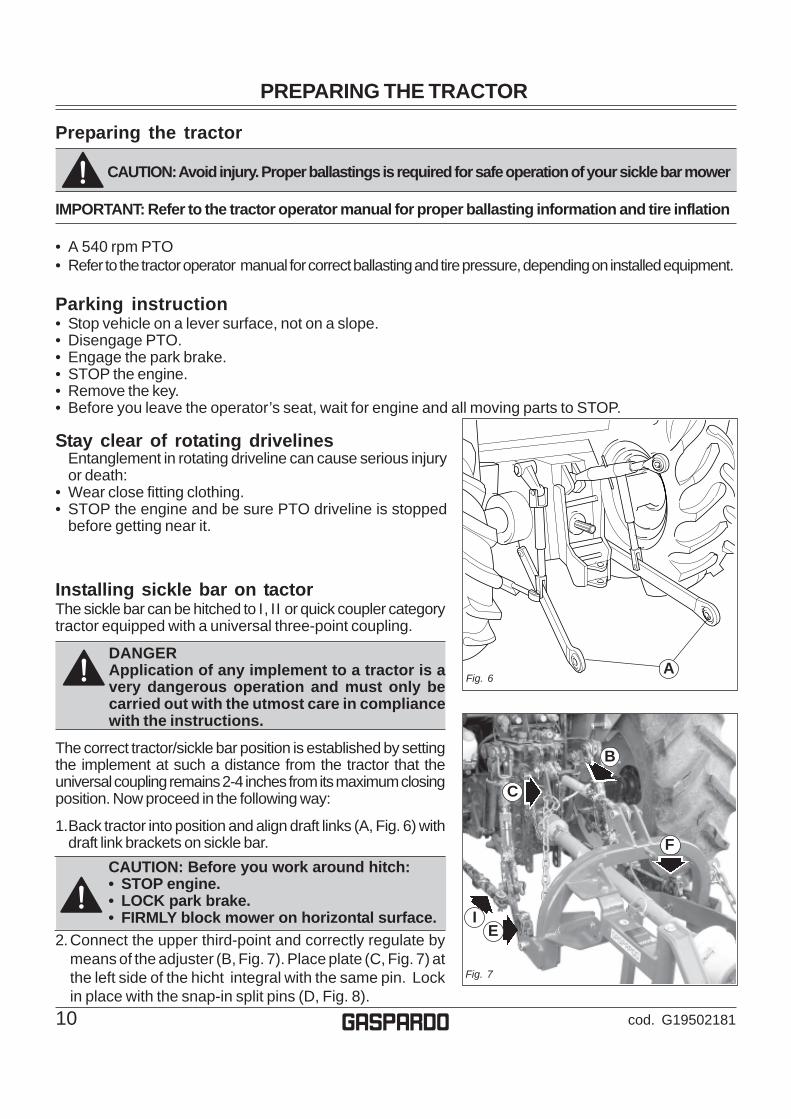
Installing sickle bar on tactorThe sickle bar can be hitched to I, II or quick coupler categorytractor equipped with a universal three-point coupling.
DANGERApplication of any implement to a tractor is avery dangerous operation and must only becarried out with the utmost care in compliancewith the instructions.
The correct tractor/sickle bar position is established by settingthe implement at such a distance from the tractor that theuniversal coupling remains 2-4 inches from its maximum closingposition. Now proceed in the following way:
1.Back tractor into position and align draft links (A, Fig. 6) withdraft link brackets on sickle bar.
Preparing the tractor
CAUTION: Avoid injury. Proper ballastings is required for safe operation of your sickle bar mower
IMPORTANT: Refer to the tractor operator manual for proper ballasting information and tire inflation
• A 540 rpm PTO• Refer to the tractor operator manual for correct ballasting and tire pressure, depending on installed equipment.
Parking instruction• Stop vehicle on a lever surface, not on a slope.• Disengage PTO.• Engage the park brake.• STOP the engine.• Remove the key.• Before you leave the operator’s seat, wait for engine and all moving parts to STOP.
Stay clear of rotating drivelinesEntanglement in rotating driveline can cause serious injuryor death:
• Wear close fitting clothing.• STOP the engine and be sure PTO driveline is stopped
before getting near it.
A
CAUTION: Before you work around hitch:• STOP engine.• LOCK park brake.• FIRMLY block mower on horizontal surface.
2.Connect the upper third-point and correctly regulate bymeans of the adjuster (B, Fig. 7). Place plate (C, Fig. 7) atthe left side of the hicht integral with the same pin. Lockin place with the snap-in split pins (D, Fig. 8).
Fig. 6
B
C
F
IE
Fig. 7

INSTALLING
11cod. G19502181 g
3.Hook the oscillating arms of the tractor to pins (E and F,Fig. 7). The hoisting arm (H, Fig. 8) must be fixedunderneath the tractor arm. Lock in place with the snap-insplit pins (G Fig. 8)
4.Lock the lift links using the relative chains (I, Fig. 7) andcouplings parallel to the tractor. This operation must becarried out to prevent the machine from moving in ahorizzontal direction.
5. Install PTO shaft to tractor (Fig. 9).
IMPORTANT: Sickle bar mower MUST BE level front to rear.
Make sure PTO shaft is locked on the tractor PTO prior toengagement (L). Check that the guard (M) is free to turnand fix it with the relative latch (M1).
6.Remove the guard over the cutters (16, Fig. 4) andremove the tirant (7, Fig.4).
7. Lift-up sickle bar.
8. Remove spring locking pin (N, Fig. 10) from parking stand.
9. Remove support (O and P, Fig. 10) and remount them,upside-down in their seat .
10. Fasten with spring locking pin (N, Fig. 10).
ML
D
Fig. 9
G
Fig. 8
H
N
O
P
Fig. 10
M1

INSTALLING
12 cod. G19502181g
min. 6 inches
min. 137/64 inches
Max
Min
PTO shaft adaptationThe PTO shaft, supplied with the machine, is of standardlength. Therefore it might be necessary to adapt the PTOshaft. In that case, before doing anything, consult theManufacturer for the eventual adaptation.
• The equipment installed can only be controlled by meansof the PTO shaft complete with the necessary overloadsafety (i.e. clutch) devices and guards fastened with theappropriate chain.
• Only the PTO shaft supplied by the Manufacturer must beused.
• The engine must not be running when installing andremoving the PTO shaft.
• Care must be taken regarding the safety and correctassembly of the PTO shaft.
• Use the chain provided to stop the PTO shaft from rotating.• Always check carefully that the PTO shaft guard is always
in position, both during transportation and operation.• Frequently and set intervals check the PTO shaft guard, it
must always be in excellent condition.• Before engaging the PTO, check that the set rpm
corresponds to that indicated by the sticker on theequipment.
• Before inserting the PTO, make sure that there are nopeople or animals nearby and that the rpm selectedcorresponds to that permitted. Never exceed the maximumadmissible speed.
• Watch out for the rotating universal joint.• Do not insert the PTO with the engine off or synchronized
with the wheels.• Always disconnect the PTO when the cardan shaft is at too wide an angle (never more than 10°,Fig.
12) and when it is not being used.• Only clean and grease the PTO shaft when the power take-off is disconnected, the engine is off, the
hand brake pulled and the key removed.• When not in use, place the PTO shaft on the support provided for it.• After having dismantled the PTO, place the protective cover on the PTO shaft (S, Fig. 13).
ATTENTIONComply with the manufacturer's instructions whentransporting the mowing machine.
CAUTION• When the PTO shaft is fully extended, the two tubes
must overlap by at least 6 inches (Q Fig. 11). Whenfully inserted, the minimum play must be 137/64inches (R Fig.11).
• If the implement is used on another tractor, alwayscheck the above and that the guards copletelycover the rotating parts of the PTO shaft.
S
Fig. 13
Fig. 12
Fig. 11
Q
R

INSTALLING
13cod. G19502181 g
Stability of sickle bar mower and tractor during transport
When a sickle bar is coupled to a tractor, so becoming an integral part of it for the purposes of roadtravel, the stability of the sickle bar-tractor complex may change and cause driving or operating difficulties(rearing up or side-slipping of the tractor). The condition of equilibrium can be restored by placing asufficient number of ballasts on the front of the tractor so that the weights on the two tractor axles aredistributed sufficiently evenly. To work in safety the instructions given in the highway code should befollowed; these prescribe that at least 20% of the weight of the tractor alone should be borne by the frontaxle and that the weight on the arms of the hoist should not be more than 30% of the weight of the tractoritself. These factors are summarized in the following formulas:
Z > (M x s)-(0.2 x T x i)(d+i)
The amount of ballast that should be applied according to the formula is the minimum required for circulationon the road. If for reasons of tractor performance or to improve the set-up of the sickle bar during operationit is thought necessary to raise these values, please refer to the registration document of the tractor tocheck its limits. When the formula for calculating the ballast gives a negative result it will not be necessaryto add any weight. In any case, as long as the limits of thetractor are respected, a suitable quantity of weights may beapplied in order to ensure greater stability during travel. Thesymbols have the following meanings:
M Kg Mass weighing on arms off hoist with full load (Technical data table)
T Kg Mass of tractor
Z Kg Total mass of ballast
i m Tractor wheelbase, that is, the horizontaldistance between the tractor axles
d m Horizontal distance between the centre of gravityof the ballast and the front axle of the tractor
s m Horizontal distance between the centre of gravity ofthe operating machine and the back axle of the tractor
169/64
inches
Fig. 14
(please see Fig. 14 for reference):

INSTALLING
14 cod. G19502181g
Parking instructions• Stop vehicle on a level surface, not on a slope.• Disengage PTO.• Engage the park brake.• STOP the engine.• Remove the key.• Before you leave the operator’s seat, wait for engine and all moving parts to STOP.
Stay clear of rotating drivelinesEntanglement in rotating driveline can cause serious injury or death:• Wear close fitting clothing.• STOP the engine and be sure PTO driveline is stopped before getting near it.
REMOVING
15cod. G19502181 g
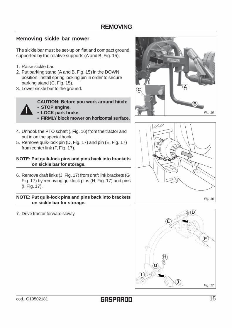
Removing sickle bar mower
The sickle bar must be set-up on flat and compact ground,supported by the relative supports (A and B, Fig. 15).
1. Raise sickle bar.2. Put parking stand (A and B, Fig. 15) in the DOWN
position: install spring locking pin in order to secureparking stand (C, Fig. 15).
3. Lower sickle bar to the ground.
CAUTION: Before you work around hitch:• STOP engine.• LOCK park brake.• FIRMLY block mower on horizontal surface.
4. Unhook the PTO schaft (, Fig. 16) from the tractor andput in on the special hook.
5. Remove quik-lock pin (D, Fig. 17) and pin (E, Fig. 17)from center link (F, Fig. 17).
NOTE: Put quik-lock pins and pins back into bracketson sickle bar for storage.
6. Remove draft links (J, Fig. 17) from draft link brackets (G,Fig. 17) by removing quiklock pins (H, Fig. 17) and pins(I, Fig. 17).
NOTE: Put quik-lock pins and pins back into bracketson sickle bar for storage.
7. Drive tractor forward slowly.
H
D
E
I
F
J
G
Fig. 16
Fig. 17
B
AC
Fig. 15

OPERATING
16 cod. G19502181g
Operate safetly
Carefully read all the instructions before using the machine; if in doubt, contact thetechnicians of the Manufacturer’s dealer. The manufacturer declines all responsibility for thenon-observance of the safety and accident prevention regulations described below.
General norms1) Pay close attention to the danger signs in this manual and on the sickle bar.2) The labels with the instructions attached to the machine give abbreviated advice for avoiding accidents.3) Carefully observe, with the help of the instructions, the safety and accident prevention regulations.4) Avoid touching moving parts in any way whatsoever.5) Any work on and adjustment to the machine must always be done with the engine switched off and
the tractor blocked.6) People or animals must not, under any circumstances, be transported on the equipment.7) It is strictly prohibited to drive the tractor, or allow it to be driven or with the equipment attached by
persons not in possession of a driver’s license, an expert or in poor conditions of health.8) Before starting the tractor and the equipment, check that all safety devices for transport and use are
in perfect working order.9) Before starting up the equipment, check the area surrounding the machine to ensure that there are
no people, especially children or pets, nearby, and ensure that you have excellent visibility.10)Use suitable clothing. Avoid loose clothing or garments with parts that could in any way get caught in
the rotating or moving parts of the machine.11) Before starting work, familiarize yourself with the control devices and their functions.12)Only start working with the equipment if all the protective devices are in perfect condition, installed
and in the safe position.13)It is absolutely prohibited to stand within the machine’s radius of action where there are moving
parts.14)It is absolutely forbidden to use the equipment without the guards.15)Before leaving the tractor, lower the implement coupled to the lift unit, stop the engine, engage the
hand brake, remove the ignition key from the control panel, cover the cutters and outer skid with therelative guards. Raise the mowing bar (transport protection) according with the instructions given inthis handbook.
16)The driver’s seat must never be left when the tractor engine is running.17)Before operating the mowing machine, check that the support struts (A and B, Fig. 15 page 15) have
been removed from underneath the implement. Make sure that the sickle bar has been correctlymounted and adjusted. Check that the machine is in perfect order and that all components subject towear and deterioration are efficient.
18)Before releasing the equipment from the third point attachment, put the hoist command lever into thelocked position and lower the support feet.
19)Only operate during daylight or with proper artificial light.20)All operations must be carried out by expert personnel, equipped with protective gloves, in a clean
and dust-free environment.21)Do not climb onto the machine while it is running, even if it is stationary.22)Before approaching the mowing bar, disengage the pto, switch off the tractor, engage the parking
brake and check that the cutters are at a complete standstill.23)The coupled implement may only be controlled through the PTO shaft complete with the necessary
safety devices for overloads and with the guards fixed with the relative latch.24)During maintenance and work operations, make sure that no other person goes near the tractor and
the implement and accidentally works the controls with the risk of causing injury to persons anddamage to property.
25)As a precaution, always set adeguate supports under the implement during assembly, servicing,cleaning or assembly work with the mowing bar raised.
OPERATING
17cod. G19502181 g
Stay clear of rotating drivelinesEntanglement in rotating driveline can cause serious injury or death:• Wear close fitting clothing• Stop the engine and be sure PTO shaft is stopped before getting near it.
CAUTION: Before you work around hitch:• STOP engine.• LOCK park brake.• FIRMLY block mower on horizontal surface.
26)DO NOT wear radio or music headphones while operating the machine. Safe operation requiresyour full attention.
27)DO NOT operate the tractor and sickle bar when you are tired or ill.
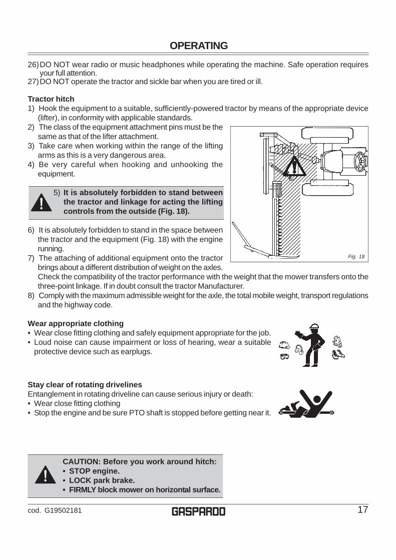
Tractor hitch1) Hook the equipment to a suitable, sufficiently-powered tractor by means of the appropriate device
(lifter), in conformity with applicable standards.2) The class of the equipment attachment pins must be the
same as that of the lifter attachment.3) Take care when working within the range of the lifting
arms as this is a very dangerous area.4) Be very careful when hooking and unhooking the
equipment.
5) It is absolutely forbidden to stand betweenthe tractor and linkage for acting the liftingcontrols from the outside (Fig. 18).
6) It is absolutely forbidden to stand in the space betweenthe tractor and the equipment (Fig. 18) with the enginerunning.
7) The attaching of additional equipment onto the tractorbrings about a different distribution of weight on the axles.Check the compatibility of the tractor performance with the weight that the mower transfers onto thethree-point linkage. If in doubt consult the tractor Manufacturer.
8) Comply with the maximum admissible weight for the axle, the total mobile weight, transport regulationsand the highway code.
Wear appropriate clothing• Wear close fitting clothing and safely equipment appropriate for the job.• Loud noise can cause impairment or loss of hearing, wear a suitable
protective device such as earplugs.
12345678901231234567890123123456789012312345678901231234567890123123456789012312345678901231234567890123123456789012312345678901231234567890123123456789012312345671234567123456712345671234567123456712345671234567123456712345671234567123456712345671234567123456712345671234567123456712345671234567123456712345671234567
Fig. 18

OPERATING - MECHANICAL LIFTING SYSTEM
18 cod. G19502181g
Fig. 23
Use of MECHANICAL lifting system (Fig. 19)
Adapting the sickle bar mowerTo ensure optium use, the sickle bar must completelyproject from the tractor (Fig. 20); three situations areshown in the Figure 21:1) hitching to a tractor normally used for mowing jobs;2) hitching to a large tractor;3) hitching to a small tractor or to certain types of tracked
vehicle.
(1) (2) (3)
Fig. 20 Fig. 21
Adjustment
• Remove safety hook (D, Fig. 22), required only fortransportation, and fit it back in the slot positioned abovethe chassis. Reduce to the minimum length in order to hookit in (E, Fig. 22) with the sickle bar to lower.
• Fit the sickle bar by adjusting the tractor tie-rods so that,when the sickle bar attachment is fitted to the three pointson the tractor, the external tip of the cutting arm isapproximately 2 inches. foward with respect to the armbase (Fig. 23).
• Using chain (F, Fig. 24) , adjust the height of the sicklebar attachment with respect to the tractor. Attach theappropriate link to the special plate hole (G, Fig. 24).
F
G
Fig. 24
D
EFig. 22
Fig. 19

OPERATING - MECHANICAL LIFTING SYSTEM
19cod. G19502181 g
Mark the link used so that the same postion may be usedeach time the sickle bar is fitted to the tractor.
• Adjusting the hoisting chain (H, Fig. 25) so that duringmowing the hoisting arm (I, Fig. 25) is free to move up anddown; in this way, the cutting arm can follow any unevennessof the ground.
So that the mower will work well, we advise you tofix the chain (H Fig. 25) to the lifting arm (I Fig. 25) atthe level of the 7th or 8th link of the chain.
• Adjust the heigt of the cutting arm from the ground withchain (J, Fig. 26). Lower the mower; when the external tipof the arm touches the ground, the inner shoe must remainapproximately 10 cm. above ground level (Fig. 26). Adjustby moving the chain links.
So that the mower will work well, we advise you to fix thechain (J, Fig. 25-26) to the equalizer (L, Fig. 25-26), leavingthe last links of the chain free.
• Adjust inclination of the cutting arm teeth using tie rod (M,Fig. 27).
• Adjust the cutting height (Fig. 28) by moving the mowingbar on the holes of the inner mowing bar support (N), and,turning the nut of the outer mowing bar support (M), bringit level with the ground.
Min. 1,2 inchesMax. 2,7 inches
ON
Fig. 28
Fig. 26
Fig. 25
H
I
J
1°
7°/8°
L
MFig. 27

OPERATING - MECHANICAL LIFTING SYSTEM
20 cod. G19502181g
Mowing
• Remove the supports (P and Q, Fig. 29) and remount them,upside-down in their seat . Install spring locking pin in orderto secure parking stand (R).
TU
• Remove tie rod (S, Fig. 30) from the cutting arm and secureit in its seat.
• The sickle bar is fitted with a safety device for protectionagainst obstacles. If this device is tripped by impact with anobstacle, stop the tractor without raising the cutting arm.Check that the cardan shaft has not become seperated, ifso, reassemble it. Position the safety tie rod parallel tothe ground, and reverse the tractor until the safety tierod hooks up again. If the tie rod releases easly, adjustspring (T, Fig. 31) using nut (U, Fig. 31) which should betightened half turn at a time.
For successful mowing and to avoid jamming, we advise youto:• Set and maintain the power take-off at a constant rate
of 540 rpm to ensure correct blade frequency;• compatibly with the soil conditions and the type of grass,
maintain a steady work speed: no slower than 5 mph to favorthe discharging of the mown grass and no faster than 6.2mph to avoid breaking or damaging the machine's structure.
• if the grass is tangled or flattened, keep the cutting bar grazingthe ground.
Fig. 31
R
Q
P
Fig. 29
Fig. 30
S
OPERATING - MECHANICAL LIFTING SYSTEM
21cod. G19502181 g
ATTENTIONIf the blades becomes jammed, it is advisable to operate carefully wearing suitable personal protection.All the maintenance, adjustments and work preparation operations, must be carried out with the tractor strictlyswitched off and properly stationary, with the ignition key turned off and the sickle bar on the ground.
CAUTION• Always raise the implement in order to reverse or change direction.• The cutting arm should not be raised abruptly in order to avoid damaging the cutting blades.• Power take-off must not exceed 540 r.p.m.• Never run the engine at maximum power while mowing.• In order to prevent breakages or damage, the speed of the tractor must never exceed 6.2 mph when the
implement is working.
DANGERThe mowing machine has sharp cutting blades. Always make sure that there are no persons, domesticanimals, electrical cables, pipes and so forth, within the field of action of the implement.

OPERATING - HYDRAULIC LIFTING SYSTEM
22 cod. G19502181g
Fig. 32Use of HYDRAULIC lifting system (Fig. 32)
D
A
E
CA D
B
To install the hydraulic lifting kit of the mower, on versionswith mechanical lifting, it is necessary to remove some partsof the equipment.
Figure 33 shows the parts that are to be removed from theequipment:A - arm chain;B - hinge chain;C - lifting arm;D - equalizer.
Take off the hinge chain (B) and the lifting arm (C).
Take off the equalizer (D) and the arm chain (A Fig. 34),removing and then putting back the safety hook linkage (E).
Fig. 33
Fig. 34

OPERATING - HYDRAULIC LIFTING SYSTEM
23cod. G19502181 g

OPERATING - HYDRAULIC LIFTING SYSTEM
24 cod. G19502181g
Adapting the sickle bar mower
To ensure optium use, the sickle bar must completely projectfrom the tractor (Fig. 35); three situations are shown in theFigure 36:
1) hitching to a tractor normally used for mowing jobs;2) hitching to a large tractor;3) hitching to a small tractor or to certain types of tracked
vehicle.
(1) (2) (3)
Fig. 36
Fig. 37
Fig. 38
C
B A
A1 A2 A3
C1C2 C3
B
Fig. 35
When the frame joint is moved (A, Fig. 37), the position ofthe stop bushing (C, Fig. 37) of the cylinder linkage mustconsequently be changed, according to the cases shown infigures 37 and 38.
Connections between frame joint andstop bushing for the movement of themowing bar.

OPERATING - HYDRAULIC LIFTING SYSTEM
25cod. G19502181 g
Min. 1,2 inchesMax. 2,7 inches
H
F
G
D
E
J I
Fig. 40
Fig. 41
Fig. 42
Fig. 43
Fig. 39
Adjustment
• Remove safety hook (D, Fig. 39), required only fortransportation, and fit it back in the slot positioned abovethe chassis. Reduce to the minimum length in order tohook it in (E, Fig. 39) with the sickle bar to lower.
• Fit the sickle bar by adjusting the tractor tie-rods so that,when the sickle bar attachment is fitted to the three pointson the tractor, the external tip of the cutting arm isapproximately 2 inches. foward with respect to the armbase (Fig. 40).
• Using chain (F, Fig. 41) , adjust the height of the sicklebar attachment with respect to the tractor. Attach theappropriate link to the special plate hole (G, Fig. 41).Mark the link used so that the same postion may be usedeach time the sickle bar is fitted to the tractor.
• Adjust inclination of the cutting arm teeth using tie rod (H,Fig. 42).
• Adjust the cutting height (Fig. 43) by moving the mowingbar on the holes of the inner mowing bar support (I), and,turning the nut of the outer mowing bar support (J), bringit level with the ground.

OPERATING - HYDRAULIC LIFTING SYSTEM
26 cod. G19502181g
Using the lifting device
Once you have positioned the equipment, prepare it formowing:• release the blade tie rod;• remove the support prop;• remove the blade protection.
Operation of lifting device
To operate the device, put the spring (S, Fig. 45) in position(S1, Fig.46) (under the cylinder rod), so that the cylinderbracket (T, Fig. 45) is released forwards towards position(T1, Fig. 46).
Climb into the tractor and operate the hydraulic distributorto lower the blade (U, Fig. 44) into the mowing position.
CAUTION: While working regularly checkthat the bracket (T) is still resting along thecylinder rod (Fig. 47).
Fig. 44
Fig. 46
Fig. 47
ST
U
T1
S1
T
S
T
Fig. 45

OPERATING - HYDRAULIC LIFTING SYSTEM
27cod. G19502181 g
Mowing on flat ground(or ground with small depressions)
For mowing on flat ground, couple the lever (V) with tie rod(W) and the rod (Z) in position (X) of Figure 48. Lastly insertthe lifting device as described in the previous paragraph.
+16°
30 c
m
T
+30°
-10°
With the rapid lifting device engaged, the bar (U, Fig. 49)has a negative inclination of -10° and a positive one of +16°(Fig. 50) with respect to the horizontal plane during mowing.This system has been devised for mowing quickly and safelyon flat ground or ground with small depressions.
The operation of the lifting device up to the stop ofthe bracket on the cylinder (T, Fig. 51) allows theequipment to be raised by approx. 12 inches fromthe ground and, at the same time, an inclination ofthe blade (U, Fig. 51) of + 30°, so that the end offield maneuvers can be carried out.
Fig. 48
Fig. 49
Fig. 50
Fig. 51
Z
X
V
U
U
U
W

OPERATING - HYDRAULIC LIFTING SYSTEM
28 cod. G19502181g
Mowing on slopes
Figures 52 and 53 show various types of mowing on slopingground (banks, canals, etc.).
+90
-75
CAUTION: For mowing on surfaces that arenot parallel to the tractor plane, werecommend removing the moving guidefrom the outer mowing bar support.To mount pulling of Fig. 54 in order to improvethe excursion and use of the sickle bar.
For mowing on sloping ground, disable the lifting (V) deviceas shown in Figure 55 and couple the lever (W) with tie rod(Z) and the rod (X) in position (Y) as shown in Figure 55.
In this way the bar can be adjusted with the hydraulic cylinderto mow at different angles: from -75° to +90° with respect tothe horizontal plane formed by the tractor (Fig. 56).
IMPORTANT:The sickle bar can operates in each position between-75° to +90°.
Fig. 53
Fig. 54
Fig. 55
Fig. 56
Fig. 52
Z
Y
W
X V

OPERATING - QUICK COUPLER
29cod. G19502181 g
Quick Coupler
The Quick Coupler must be used only with hydrauliclifting system.
1) Install hitch Quick Coupler (A, Fig. 57) on the tractor (seetractor operator manual).
2) Parking the sickle bar on a flat and compact groundsupported by the relative supports. Then slowly movethe tractor back until the Quick Coupler (A) is in rangewith the point hitches (B and C, Fig. 57).
CAUTION: Before you work around hitch:• STOP engine.• LOCK park brake.• FIRMLY block mower on horizontal surface.
3) Raise the Quick Coupler (A, Fig. 57) and make surethat sickle bar hitch is in the right position (E, Fig. 58).
A
D DB
CC
E
Fig. 57
Fig. 58
Removing sickle bar mower with QuickCoupler
1. Raise sickle bar.2. Put parking stand (F and G, Fig. 59) in the DOWN position:
install spring locking pin in order to secure parking stand(H , Fig. 59).
3. Lower sickle bar to the ground.4. Raise the two Quick Coupler levers (D, Fig. 57) to unloch
sickle bar.5. Lower Quick Coupler till further free the sickle bar.
G
FH
Fig. 59
OPERATING
30 cod. G19502181g
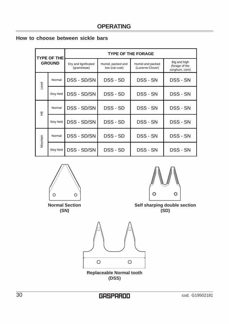
Normal Section(SN)
Self sharping double section(SD)
Replaceable Normal tooth(DSS)
How to choose between sickle bars
Dry and lignificated (gramineae)
Humid, packed and low (cat coat)
Humid and packed (Lucerne-Clover)
Big and high (forage of the
sorghum, corn)
Normal DSS - SD/SN DSS - SD DSS - SN DSS - SN
Stny field DSS - SD/SN DSS - SD DSS - SN DSS - SN
Normal DSS - SD/SN DSS - SD DSS - SN DSS - SN
Stny field DSS - SD/SN DSS - SD DSS - SN DSS - SN
Normal DSS - SD/SN DSS - SD DSS - SN DSS - SN
Stny field DSS - SD/SN DSS - SD DSS - SN DSS - SN
Mou
ntai
n
TYPE OF THE GROUND
TYPE OF THE FORAGE
Leve
lH
ill

SERVICE MACHINE SAFETLY
31cod. G19502181 g
Practice safe maintenance• Understand service procedure before doing work. Keep area clean and dry. To avoid ...
• Never lubricate, service, or adjust machine while it is moving. Keep safety devices inplace and in working condition. Keep hardware tight.
• To prevent from getting caught, keep hands, feet, clothing, jewelry, and long hair away fromany moving parts.
• Before servicing machine, lower it to the ground. Disengage all power and stop the vehicleengine. Lock vehicle park brake and remove the key.
• Securely support any machine elements that must be raised for maintenance.• Keep all parts in good condition and properly installed. Fix damage immediately. Replace
worn or broken parts. Remove any buildup of grease, oil, or debris.• Unauthorized modifications to the machine may impair its function and safety.
Wear appropriate clothing• Wear close fitting clothing and safety equipment appropriate for the job.• Loud noise can cause impairment or loss of hearing, wear a suitable protective device
such as earplugs.• Do not wear radio or music headphones while servicing the machine. Safe servicing
requires your full attention.
Stay clear of rotating PTO shaftEntanglement in rotating driveline can cause serious injury or death:• Stop the engine and be sure PTO shaft is stopped before getting near it.
MaintenanceVarious servicing operations are listed in the following paragraphs. Lower running costs and longer machine lifedepend on constant and methodical compliance with these operations.During work and maintenance operations, use suitable personal protective gear:
CAUTION• The given frequencies are indicative and refer to normal conditions of use. They may therefore
be subject to variations in relation to the type of service, a more or less dusty environment,seasonal factors, etc.
• In the case of heavy-duty conditions, the maintenance operations should obviously be morefrequent.
• Before injecting grease into the lubricators, the greasing points must be thoroughly cleanedto prevent mud, dust or foreign bodies from mixing with the lubricant, thus reducing lubricatingeffect.
ATTENTIONIt is absolutely essential to disengage the tractor pto, lower the mowing machine, switch off thetractor, ensure that this is at a complete standstill and remove the key before servicing, adjustingthe implement for work. All assembly operations must be carried out on a work bench.
• Always keep oils and greases well away from children’s reach.• Always thoroughly read the warnings and precautions indicated on the containers.• Avoid contact with the skin.• Always thoroughly and fully wash after use.• The utilized oils should be treated in compliance with the current laws in force.

SERVICE MACHINE SAFETLY
32 cod. G19502181g
Fine pitch screws CLASS
6.6 8.8 10.9 12.9
M8 x 1 15 (11) 26 (19) 36 (26.5) 44 (32.5)
M10 x 1.25 30 (22) 52 (38) 74 (54) 88 (65)
M12 x 1.25 51 (37.5) 91 (67) 127 (94) 153 (113)
M14 x 1.5 81 (60) 143 (105) 201 (148) 241 (178)
M16 x 1.5 120 (88) 214 (158) 301 (222) 361 (266)
M18 x 1.5 173 (127) 308 (227) 433 (319) 520 (384)
M20 x 1.5 242 (178) 431 (318) 606 (447) 727 (536)
M22 x 1.5 321 (237) 571 (421) 803 (592) 964 (711)
M24 x 2 411 (303) 731 (539) 1028 (758) 1234 (910)
M27 x 2 601 (443) 1070 (790) 1504 (1110) 1806 (1333)
M30 x 2 832 (614) 1480 (1090) 2081 (1535) 2498 (1843)
(metric)
(Table 1)
• Do not proceed with maintenance and cleaning if the power take-off has not been disconnected first,the engine power off, the hand brake pulled and the tractor blocked with a wooden block or stone of theright size under the wheels.
• Periodically check that the bolts and nuts are tight, and if necessary tighten them again. For this itwould be advisable to use a torque wrench, respecting the values of 52 Nm for M10 bolts, resistanceclass 8.8, and 143 Nm for M14 bolts resistance class 8.8 (Table 1: Bolts tightening torques).
• During assembling, maintenance, cleaning, fitting, etc., with the mowing machine raised, place adequatesupports under the equipment as a precaution.
• The spare parts must correspond to the manufacturer’s specifications. Use only original spares.
Bolts tightening torques - settings given in Nm (lb-ft)
Fig. 60
B
A2
Hazard bar
The hazard bar has been included with the equipment of themachine for safety reasons, to indicate the space occupiedby the mower at work. For working, position the hazard barin position (A1, Fig. 60) and lock it in place with the screw(B). For transport put it in position (A2).
A1
SERVICE
33cod. G19502181 g
Lubrification
WARNING: • Firmly block sickle bar on horizontal surface.• Always keep oils and greases well away from children’s reach.• Always thoroughly read the warnings and precautions indicated on the
containers. Avoid contact with the skin.• Always thoroughly and fully wash after use. The utilized oils should be
treated in compliance with the current anti-pollution laws.
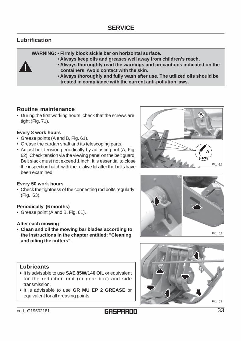
Routine maintenance• During the first working hours, check that the screws are
tight (Fig. 71).
Every 8 work hours• Grease points (A and B, Fig. 61).• Grease the cardan shaft and its telescoping parts.• Adjust belt tension periodically by adjusting nut (A, Fig.
62). Check tension via the viewing panel on the belt guard.Belt slack must not exceed 1 inch. It is essential to closethe inspection hatch with the relative lid after the belts havebeen examined.
Every 50 work hours• Check the tightness of the connecting rod bolts regularly
(Fig. 63).
Periodically (6 months)• Grease point (A and B, Fig. 61).
After each mowing• Clean and oil the mowing bar blades according to
the instructions in the chapter entitled: "Cleaningand oiling the cutters".
A
A
Lubricants• It is advisable to use SAE 85W/140 OIL or equivalent
for the reduction unit (or gear box) and sidetransmission.
• It is advisable to use GR MU EP 2 GREASE orequivalent for all greasing points.
Fig. 61
Fig. 62
Fig. 63
B

SERVICE
34 cod. G19502181g
Cleaning and oiling the sickle bar
DANGERCleaning and oiling are very dangerous operations.Always comply with the following instructions:• Lift the implement by means of the lift links in a flat place
where it cannot slip;• Operate the mowing bar, checking that there are no
persons or animals in the vicinity;• Brake the tractor and make sure it is unable to move;• Wash the sickle bar with a jet of pressurized water,
standing at least one and a half meters away fromthe implement;
• Switch off the tractor, remove the starter key and disengagethe pto;
• Check the condition of the cutters;• When the mowing bar is dry, oil the cutters with very
viscous oil;• Operate the sickle bar for a few seconds, checking that
there are no persons or animals in the vicinity;• Switch off the tractor, remove the starter key and disengage
the pto;• Fit the guards over the cutters and outer skid (C Fig. 60)
Each start of season
At the start of each season it is important to check thatthe connection between the tooth-holding bar (D Fig.61) and the blade guide (E) is correct.After many hours of work, wear of the blade guide materialmay be seen, and this will cause an increase in the couplingtolerance with the tooth blade.It is therefore advisable to restore the correct tolerance:• unscrew the blade guide (Fig. 61);• remove one or more shims (Fig. 62);• put the blade guide back in the same position.
IMPORTANT: When replacing the teeth or the tooth-holding bar, carry out the check described above.When required, put back the shims to avoid stripingor damage.
Fig. 60
Fig. 61
Fig. 62
D
E
C

SERVICE
35cod. G19502181 g
StorageIt is advisable to proceed in the following way at the end ofthe season or if the machine is to remain inactive for a longperiod of time:• Treat the implement in compliance with the instructions
given in the chapter entitled: "Cleaning and oiling thecutters".
• Carefully check for any damaged or worn parts and replacethese as necessary.
• Fully torque all screws and bolts.• Apply a little lubricant to the unpainted parts.• Protect the entire implement with a cover.• Lastly, store the implement in a dry place where it cannot
be tampered with by unauthorized persons; the mowingmachine must be set-up on flat and compact ground,supported by the relative supports (F and G, Fig. 67).
Careful compliance with these instructions will be allto the advantage of the user who will be sure to usean implement in perfect conditions when work beginsagain.
G
F
Fig. 67

SERVICE
36 cod. G19502181g
Extra maintenance
Fig. 70
Fig. 69
H
Fig. 68
I
J
ML
N
Replacement of section-holding bar (L fig. 70)• With the implement resting on the ground, open the mowing
bar.• Remove the expansion pin (H, Fig. 68) and pull out the
section-holding bar (Fig. 69) with the hooking tie rod (I Fig.69).
• Insert the new section-holding bar and lock it in place withthe expansion pin. Lubricate the cutters with very viscousoil during the assembly phase.
Replacement of sections (J fig. 70)• With the implement resting on the ground, open the mowing
bar.• Remove the expansion pin (H, Fig. 68) and slide out the
section-holding bar (Fig. 69).• Remove the damaged section using a pin punch (7 Fig. 4
on page 6).• Rivet a new section with the rivets provided (J Fig. 70).• Insert the section-holding bar and lock it in place with the
expansion pin.
Replacement of tooth-holding bar (riveted) (N Fig. 70)• With the implement resting on the ground, open the mowing
bar.• Remove the expansion pin (H, Fig. 68) and slide out the
tooth-holding bar (Fig. 69).• Insert the new tooth-holding bar and lock it in place with the
expansion pin.
Replacement of tooth (riveted) (M Fig. 70)• With the implement resting on the ground, open the mowing
bar.• Remove the expansion pin (H, Fig. 68) and slide out the
tooth-holding bar (Fig. 69).• Remove the damaged tooth using a pin punch.• Rivet a new tooth with the rivets provided (M Fig. 70).• Insert the tooth-holding bar and lock it in place with the
expansion pin.
ATTENTIONIt is absolutely essential to disengage the tractorpto, lower the mowing machine, switch off thetractor, ensure that this is at a complete standstilland remove the key before servicing, adjustingthe implement for work. All assembly operationsmust be carried out on a work bench.
SERVICE
37cod. G19502181 g
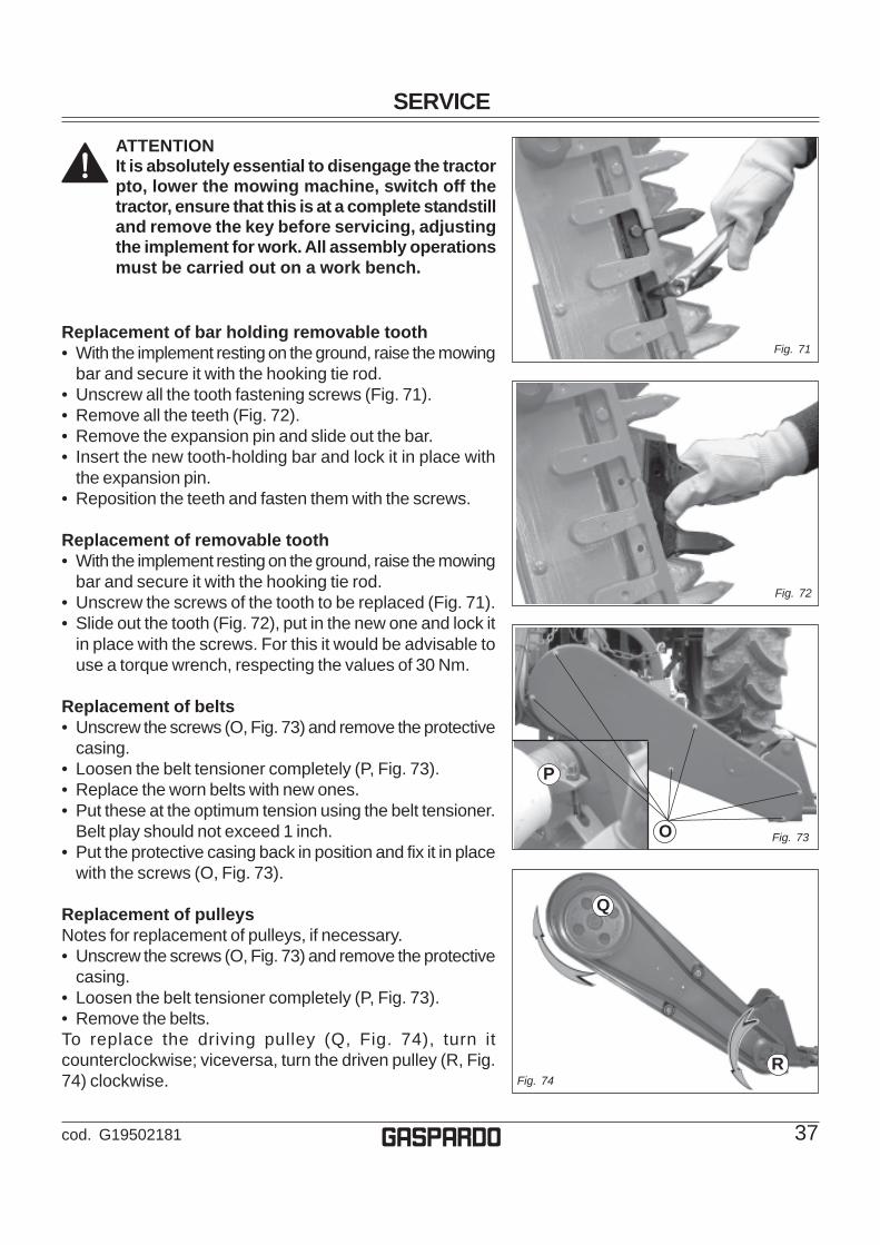
Fig. 72
Fig. 71Replacement of bar holding removable tooth• With the implement resting on the ground, raise the mowing
bar and secure it with the hooking tie rod.• Unscrew all the tooth fastening screws (Fig. 71).• Remove all the teeth (Fig. 72).• Remove the expansion pin and slide out the bar.• Insert the new tooth-holding bar and lock it in place with
the expansion pin.• Reposition the teeth and fasten them with the screws.
Replacement of removable tooth• With the implement resting on the ground, raise the mowing
bar and secure it with the hooking tie rod.• Unscrew the screws of the tooth to be replaced (Fig. 71).• Slide out the tooth (Fig. 72), put in the new one and lock it
in place with the screws. For this it would be advisable touse a torque wrench, respecting the values of 30 Nm.
Replacement of belts• Unscrew the screws (O, Fig. 73) and remove the protective
casing.• Loosen the belt tensioner completely (P, Fig. 73).• Replace the worn belts with new ones.• Put these at the optimum tension using the belt tensioner.
Belt play should not exceed 1 inch.• Put the protective casing back in position and fix it in place
with the screws (O, Fig. 73).
Replacement of pulleysNotes for replacement of pulleys, if necessary.• Unscrew the screws (O, Fig. 73) and remove the protective
casing.• Loosen the belt tensioner completely (P, Fig. 73).• Remove the belts.To replace the driving pulley (Q, Fig. 74), turn itcounterclockwise; viceversa, turn the driven pulley (R, Fig.74) clockwise. Fig. 74
Fig. 73O
P
Q
R
ATTENTIONIt is absolutely essential to disengage the tractorpto, lower the mowing machine, switch off thetractor, ensure that this is at a complete standstilland remove the key before servicing, adjustingthe implement for work. All assembly operationsmust be carried out on a work bench.

TRANSPORT ON THE ROAD
38 cod. G19502181g
Transport on road
For transport, adjust and fix the chains of the side lifting armsof the tractor; lift the mowing bar (Fig. 75); secure it with thehooking tie rod (A, Fig. 76); slide in the safety hook (B, Fig.76); cover the cutting blades and the outer mowing barsupport with the guards provided (Fig. 77); lift the implement;put the hydraulic lifting command lever in the locked position.
Transport on Road• When driving on public roads, be sure to follow the
highway code of the country involved.• Any transport accessories must be provided with suitable
signs and guards.• It is very important to remember that road holding
capacity as well as direction and braking capacity canbe influenced, sometimes con-siderably, by equipmentbeing either carried or towed.
• When negotiating curves, be aware of the variation incentrifugal force exerted in a position other than that ofthe center of gravity, with and without the equipment intow. Also pay greater attention on sloping roads or ground.
• For displacements beyond the work area, the equipmentmust be placed in the transportation position.
• When the dimensions of carried or partially-carriedequipment conceal the tractor’s signalling and lightingdevices, these must also be installed on the equipmentitself, in conformity with regulations of the highway codeof the country involved. When in operation make sure thatthe lighting system is in perfect working order.
Fig. 75
Fig. 77
BA
Fig. 76

DEMOLITION AND DISPOSAL
39cod. G19502181 g
Demolition and disposal
This operation is to be carried out by the customer.Before demolishing the machine, you are advised to carefully check its physical condition and ascertainwhether there are any parts of the structure that may be susceptible to structural collapse or breakageduring demolition.
The customer should operate in compliance with the environment protection laws in force in his/hercountry.
CAUTIONThe machine demolition operations should be carried out by skilled personnel only,equipped with suitable protective clothing (safety footwear and gloves) and auxiliarytools and equipment. All the disassembly operations for demolition should be carriedout with the machine stopped and detached from the tractor.
Before demolishing the machine, you are advised to render harmless all the parts that may be a sourceof danger and therefore:
• scrap the structure using specialized firms,• remove any electrical apparatus according to the laws in force,• collect oils and greases separately, to be disposed of through specialized firms, in accordance with
the regulations of the country in which the machine was used.
When the machine is demolished the identification label must be destroyed together with this manual.

ASSEMBLY
40 cod. G19502181g
Foreword
This chapter describes the phases involved in assembling a crated mower. When handling andassembling the unit, and subsequently during use and maintenance, always use suitable personalprotection devices (A): always wear suitable clothing and the indicated protections. See the operatingmanual supplied with the unit for indication of the symbols used in this manual. When handling the unit, liftit by hooking up the special attachments and using a suitable hoist or crane rated for the weight of theunit. This operation is quite dangerous and must only be performed by prepared, responsible personnel.The machine weight is indicated on the ID label. The hook-up points are identified by the "hook" symbol(B). When moving the unit, make certain that all protections and safety devices are in place.
A
B
C
A B
TYPETYPE
A B C(mm - inch) (kg - lb)(mm - inch) (mm - inch)
FBR 1.30 (X2) 2340 - 92 700 - 27.5 740 - 29 460 - 1012FBR 1.45 (X2) 2340 - 92 700 - 27.5 740 - 29 480 - 1056FBR 1.75 (X2) 2340 - 92 700 - 27.5 740 - 29 520 - 1144FBR 2.05 (X2) 2340 - 92 700 - 27.5 740 - 29 560 - 1232FBR 1.30 (X5) 2340 - 92 1400 - 55.1 1000 - 39.4 950 - 2090FBR 1.45 (X5) 2340 - 92 1400 - 55.1 1000 - 39.4 1000 - 2200FBR 1.75 (X5) 2340 - 92 1400 - 55.1 1000 - 39.4 1100 - 2420FBR 2.05 (X5) 2340 - 92 1400 - 55.1 1000 - 39.4 1200 - 2640
Dimensions and weight

ASSEMBLY
41cod. G19502181 g
Sickle bar components
1) THIRD POINT LINKAGE FRAME.2) SUPPORT.3) POWER PTO PLATE.4) FRONT PLATE.5) TRIP TIE-ROD.6) REAR FRAME.7) BLADE HOLDER.8) MECHANICAL LIFTING SYSTEM8) HYDRAULIC LIFTING SYSTEM
1
2
5
6
3 4
7
8

ASSEMBLY
42 cod. G19502181g
Nr. 13
Install the support on the third point linkageframe
Install the trip tie-rod on the third pointlinkage frame
Install the support on the third point linkageframe
Install the plate on the power take-off
1.0 2.0
3.0 4.0
ASSEMBLY
43cod. G19502181 g
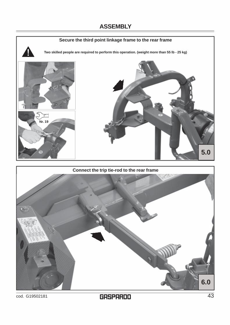
Nr. 19
Secure the third point linkage frame to the rear frame
Two skilled people are required to perform this operation. (weight more than 55 lb - 25 kg)
Connect the trip tie-rod to the rear frame
5.0
6.0

ASSEMBLY
44 cod. G19502181g
Nr. 10-13-17
Sickle barRemove the protection and the supplementary blade. Withdraw the blades from the blade holder
Remove the protection from the connectingrod system
7.b
Remove the blade holder expansion pinsand securing screws
7.c
7.a
CRUSHING AND PINCH POINTSMOVING MACHINERY PARTS CAN �
PINCH OR CRUSH OR FALL - �WHICH MAY CAUSE INJURY OR DEATH.
KEEP AWAYSHARP BLADES
-�Do not put hands or feet near the cutterbar. �����Blade contact can result in serious injury.�-�Stay away until all motion has stopped and ���the mower is securely blocked up.-�Keep fingers clear of cutterbar when folding ���cutterbar for transport.

ASSEMBLY
45cod. G19502181 g
Remove the blade holder nuts and washers Insert the blade holder vertically into the hinge guide
Two skilled people are required to performthis operation. (weight more than 55 lb - 25 Kg)
7.d 7.e
7.f
Insert the internal slide on the blade holder and secure it with thesupplied screws, nuts and washers
ASSEMBLY
46 cod. G19502181g
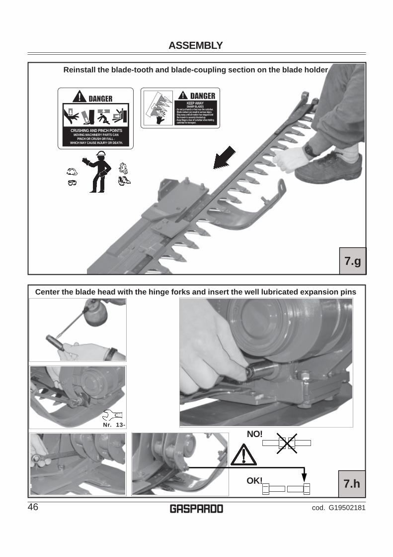
7.g
Reinstall the blade-tooth and blade-coupling section on the blade holder
Center the blade head with the hinge forks and insert the well lubricated expansion pins
7.h
Nr. 13-
NO!
OK!
CRUSHING AND PINCH POINTSMOVING MACHINERY PARTS CAN �
PINCH OR CRUSH OR FALL - �WHICH MAY CAUSE INJURY OR DEATH.
KEEP AWAYSHARP BLADES
-�Do not put hands or feet near the cutterbar. �����Blade contact can result in serious injury.�-�Stay away until all motion has stopped and ���the mower is securely blocked up.-�Keep fingers clear of cutterbar when folding ���cutterbar for transport.

ASSEMBLY
47cod. G19502181 g
Nr. 17
Nr. 10-13-17
Reinstall the protection on theconnecting rod
Install the grass guard bar7.i 7.l
Nr. 17
Nr. 7
A
Install the moving guide and hazard bar
Do not tighten securing nut (A) on the moving guidecompletely: allow for proper movement of the guide.
7.m
Nr. 13
Secure the stay on the moving guide
7.n

48 cod. G19502181g

49cod. G19502181
SPARE PARTS
g
Spare parts
Orders must be transmitted through our area dealers and should always include the following indications:
• Type, model and serial number of the machine. These data are punched on the data plate withwhich every implement is equipped.
• Code number of the required spare part. This will be found in the spare parts catalogue.
• Description of the part and required quantity.
• Means of dispatch. If this item is not indicated, the Manufacturer, while dedicating particular care tothis service, shall not be held responsible for delays in delivery caused by cases of force majeure.Transport expenses shall always be at the consignee’s charge. The goods travel at the purchaser’srisk and peril even when sold ex destination.
NOTE: The terms Right or Left indicated in the descriptions refer to the implement when viewed from therear side.
Table index
Frame Tav. 951/12 pag. 50Transmission Tav. 951/21 pag. 52Hinge Tav. 951/31 pag. 54Cutting blade (tooth riveted) Tav. 951/43 pag. 56Cutting blade (replaceable tooth)Tav. 951/53 pag. 58Hydraulic lifting system Tav. 951/63 pag. 60

SPARE PARTS
50 cod. G19502181g
TAV.
951
/12
6362 60
6967
68
1964
6566
17
74
6665
38
501837
75
76
6437 38
16
2
39
45
44 40
55
38 37
5846
45127
8
47
12 3
28
57
56
29
831
10
42
4344
45
26
63
62
60
35
35
3449
3630
36
4971
6059
87
6
61
15
13
37
3351
73 48
11
4647 14
45
38
325253
5455
45
44
4041
23
7224
25
20
6070
6968
22
21
67
NA
RR
OW
RO
AD
WAY
NO
RM
AL
RO
AD
WAY
45
9
60
70

SPARE PARTSPo
s.Co
d.D
escr
iptio
nPo
s.Co
d.D
escr
iptio
n
51cod. G19502181 g
1 2 3 4 5 6 7 8 9 10 11 12 13 14 15 16 17 18 19 20 21 22 23 24 25 26 27 28 29 30 31 32 33 34 35 36 37 38
G12
2175
91FB
R F
RAM
EG
1221
7821
JOIN
TG
1221
7600
LON
G A
RM
G12
2176
10SH
OR
T AR
MG
1221
7620
ARM
SPA
CER
G21
1200
06LI
FTE
R R
OC
KE
RG
2112
0007
AR
M S
IDE
CH
AIN
L.6
00F0
2250
667
CLE
VIS-
3/8
- GAL
VAN
ISED
- AR
T.F0
1020
323
SC
RE
W 2
0X20
0 57
37 8
.G Z
NF0
1220
288
NU
T- T
RIS
TOP
M20
F010
2056
6BO
LT M
16X2
X40
F012
2026
6N
UT-
TR
ISTO
P M
16G
1221
7810
PR
OP
TU
BE
G12
2176
50FR
ON
T P
RO
PG
1221
7800
HIN
GE
BEAR
ING
AR
MG
2103
0010
ARM
AR
TIC
ULA
TIO
NG
2112
0212
JOIN
T EL
EMEN
T FB
/SG
2112
0319
HIN
GE
AR
M S
PR
ING
FB
940
G12
2364
70D
RIV
EN A
XLE
PULL
Y PR
OTE
CTI
ON
G21
1202
15IN
NE
RP
RO
TEC
TIO
N C
AS
E F
B/S
G21
1202
16O
UTE
RPR
OTE
CTI
ON
CAS
E FB
/SG
2112
0217
INSP
ECTI
ON
OPE
NIN
G C
OVE
R-G
UAR
DG
1221
6400
TIE
RO
DF0
1200
306
NU
T M
14X2
F062
2001
16-
LOB
E H
AN
DW
HE
EL
M14
F201
2040
0SH
AFT
HO
OK
G21
0300
07TR
ACTO
R C
OU
PLIN
G P
LATE
G21
0300
35C
HA
IN L
.900
G21
0300
34FR
AME
CO
UPL
ING
G21
1203
08SA
FETY
HO
OK
CO
UPL
ING
FB9
40G
1221
7710
SAFE
TY C
HAI
N H
OO
KG
1221
7680
SLI
DIN
G R
OD
G12
2177
61S
NA
P T
IE R
OD
GU
IDE
G12
2179
50FO
RK
FO
R T
RIP
TIE
-RO
DG
6624
8064
HIN
GE
ARM
BU
SHIN
G F
B.F2
0100
504
U B
OLT
PIN
D.1
6X45
G21
0300
27R
UB
BE
R B
LOC
KS
G20
9700
67W
ASH
ER 5
4X5X
32
39 40 41 42 43 44 45 46 47 48 49 50 51 52 53 54 55 56 57 58 59 60 61 62 63 64 65 66 67 68 69 70 71 72 73 74 75 76
F201
0004
7P
ING
2101
0042
BU
SH
ING
1.-2
. PO
INT
F201
0011
5G
AS
PAR
DO
PIN
22X
144
ZNF2
0100
035
PIN
G12
2176
60TH
IRD
PO
INT
BU
SH
F022
0050
7S
NA
P P
IN D
9 B
/83
G13
8123
11C
HA
IN W
ITH
SP
RIN
G C
ATC
HF0
2200
562
SP
LIT
PIN
F022
0027
2S
PLI
T P
IN 1
0 X
60 1
336
GA
LVA
N.
F022
0025
9S
PLI
T P
IN 8
X45
133
6F0
2200
195
SP
LIT
PIN
4 X
25 1
336
GA
LVA
N.
F022
0026
0S
PLI
T P
IN 8
X60
133
6 G
ALV
AN
.F0
1020
176
BOLT
M 1
2X13
0G
2112
0301
CO
NE
DIS
CO
NN
EC
T FB
940
F024
0001
3S
PR
ING
G 3
8X75
SP
EC
IAL
SP
RIN
GS
G22
3100
47R
EAR
AR
M B
USH
ING
DP
F012
3005
8S
ELF
LO
CK
ING
NU
T M
12X
1,25
F010
2047
6BO
LT M
10X
30F0
1220
233
NU
T TR
ISTO
P M
10F0
1020
512
BOLT
M 1
2X35
F010
2007
2BO
LT M
8X5
0G
2097
0140
WAS
HER
20X
2X8,
5F0
1230
034
SE
LF L
OC
KIN
G N
UT
M8X
1,25
F014
3005
9W
AS
HE
R D
8 D
IN 6
798
D.IN
T.ZN
F012
0024
4N
UT
M8
F010
2051
0BO
LT M
12X
30F0
1430
071
WA
SH
ER
D12
DIN
679
8 D
.INT.
ZNG
2097
0035
WAS
HER
32X
4X13
F010
2040
3BO
LT M
6X1
6F0
1410
037
PLA
NE
WA
SH
ER
D.6
F022
5068
0TH
RE
AD
ED
INS
ER
T M
6X13
ZN
F010
2009
2BO
LT 8
X11
0 57
37 8
.G G
ALV
AN
IZ.
G12
2176
91TR
IP T
IE-R
OD
G21
1202
11C
UTT
ER
BA
R T
IE R
OD
FB
/SF0
1410
124
PLA
NE
WA
SH
ER
D. 2
0G
1221
7970
NAR
RO
W R
OAD
WAY
AR
MG
1221
7980
ARM
SPA
CER
F010
2031
7BO
LT M
20X2
,5X1
50
TAV.
951
/12
FRA
ME
SPARE PARTS
52 cod. G19502181g
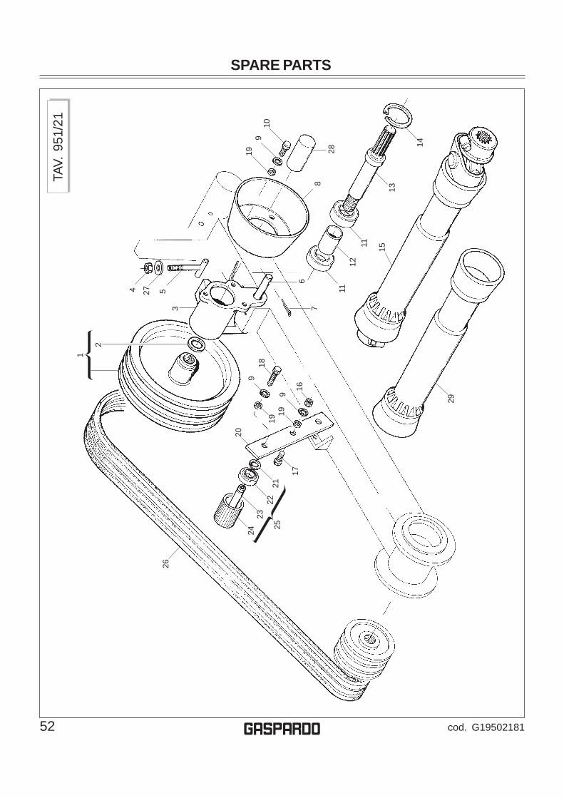
TAV.
951
/21
1
4 27 5
2
19
8
67
910
28
9
1919
9
16
1112
11
13
14
15
18
29
17
2221
2324
26
25
3
20

SPARE PARTSPo
s.Co
d.D
escr
iptio
nPo
s.Co
d.D
escr
iptio
n
53cod. G19502181 g
1 2 3 4 5 6 7 8 9 10 11 12 13 14 15 16 17 18 19 20 21 22 23 24 25 26 27 28 29
G21
1201
173
GR
OO
VE D
RIV
ING
PU
LLEY
G20
9701
29W
ASH
ER 4
8X3X
30-5
G21
0300
15PT
O S
UPP
OR
TF0
1200
306
NU
T M
14X2
G21
1203
18BE
LT R
EGIS
TER
ASS
Y. F
B940
G21
1200
13IN
TER
M. T
RAN
SM. S
UPP
. PIN
F022
0022
7S
PLI
T P
IN 5
X30
133
6 G
ALV
AN
.F0
5150
403
POW
ER T
AKE-
OFF
PR
OTE
CTI
ON
HO
US
F014
3005
9W
AS
HE
R D
8 D
IN 6
798
D.IN
T.ZN
F010
2043
2BO
LT M
8X1
6F0
4010
174
BE
AR
ING
620
6 2R
SG
2103
0020
SPAC
ERG
2112
0152
POW
ER T
AKE-
OFF
FB
F020
5063
7S
TOP
RIN
G 6
2 U
NI 7
437-
75F0
8011
755
UN
IVE
RS
AL
JOIN
T B
3 10
00 A
MF0
1200
244
NU
T M
8F0
1060
043
BOLT
8 X
35 5
732
4.6
GA
LVA
NIZ
ED
F010
2044
0BO
LT M
8X2
5G
2097
0140
WAS
HER
20X
2X8,
5G
2112
0226
BELT
TIG
HTE
NE
R R
OLL
ER
S S
UP
PO
RT
F020
5060
7S
TOP
RIN
G 1
7 U
NI 7
435-
75F0
4010
161
BE
AR
ING
620
3G
2112
0119
3 G
RO
OVE
P.T
IGH
TEN
. PIN
G66
2481
07BE
LT T
IGH
TEN
ER
L.7
0 FB
G21
1201
21TI
GH
TEN
ER
RO
LLE
R 3
G. C
PF0
6010
240
BELT
S- B
93
F014
1008
8P
LAN
E W
AS
HE
R D
.14
G66
2482
27PO
WER
TAK
E-O
FF P
RO
TEC
TIO
N H
OU
SF0
8011
124
SAFE
TY G
UAR
D A
M
TAV.
951
/21
TRA
NSM
ISSI
ON

SPARE PARTS
54 cod. G19502181g
TAV.
951
/31
353
2
1753
18 16 135
6
3
232 20
50
49
12
11
10
48 8
79
4
19
2122
2324
25
2627
28
2930
3435
36
3738
29
39
31
32
33
1416
4546
4446
47
32
15
4443
45
42
40
1316
14
43
32
51
52
41
1

SPARE PARTSPo
s.Co
d.D
escr
iptio
nPo
s.Co
d.D
escr
iptio
n
55cod. G19502181 g
1 2 3 4 5 6 7 8 9 10 11 12 13 14 15 16 17 18 19 20 21 22 23 24 25 26 27 28 29 30 31 32 33 34 35 36
F022
5066
7C
LEVI
S- 3
/8- G
ALVA
NIS
ED- A
RT.
F014
3004
7W
AS
HE
R D
6 D
IN 6
798
D.IN
T.G
ALV
.F0
1420
036
FLAT
WA
SH
ER
6-6
X 1
8X2
6593
ZN
G21
1200
07A
RM
SID
E C
HA
IN L
.600
F010
2051
4BO
LT M
12X1
,75X
40G
2097
0007
WAS
HER
35X
8X13
G20
9700
35W
ASH
ER 3
2X4X
13F0
1430
071
WA
SH
ER
D12
DIN
679
8 D
.INT.
ZNF0
1200
293
NU
T M
12G
2112
0118
3-G
RO
OVE
DR
IVEN
PU
LLEY
F020
5063
7S
TOP
RIN
G 6
2 U
NI 7
437-
75F0
4010
171
BE
AR
ING
620
6 Z
F014
2006
0W
AS
HE
R 1
0,5X
30F0
1020
479
BOLT
M 1
0X35
G20
9700
99W
AS
HE
R 3
8X4X
11F0
1430
023
WA
SH
ER
D10
DIN
679
8 D
.INT.
ZNG
1223
6490
CO
NN
ECTI
NG
-RO
D S
YSTE
M G
UAR
DF0
1020
472
BOLT
10X
25 5
739
8.G
GA
LVA
NIZ
ED
G21
1202
21BL
ADE
SHAF
T SU
PPO
RT
FB/S
G12
2365
00H
ING
EF0
4010
363
BE
AR
ING
DH
K 5
025
F030
1106
9S
EA
LIN
G R
ING
DH
50X
58X
4F0
4010
409
SH
OU
LDE
R R
ING
WR
45
F041
0013
1IN
TER
NA
L IR
. RIN
G 4
5X50
X35
G21
1202
23H
ING
E S
PIN
DLE
FB
/SG
2112
0126
CO
NIC
PIN
FB
G21
1201
36P
IN S
PAC
ER
FB
G21
1201
27P
IN G
RU
B-S
CR
EW
FB
F020
5064
1S
TOP
RIN
G 7
2 U
NI 7
437-
75G
6624
8111
DU
ST
CO
VE
R H
ING
E F
BG
2112
0153
KIT
- IN
T. C
ON
N. R
OD
BE
AR
ING
FB
F011
0001
1SP
HER
E N
IPPL
E M
6X1/
AF0
4010
362
BE
AR
ING
DH
K 2
538
G21
1201
28P
IN H
ING
E C
ON
NE
CTI
NG
RO
D F
BG
2117
0020
HIN
GE
EC
CE
NTR
ICG
2117
0021
OU
TER
CO
NN
EC
TIN
G R
OD
37 38 39 40 41 42 43 44 45 46 47 48 49 50 51 52 53
F020
5061
7S
TOP
RIN
G 3
0 U
NI 7
435-
75G
2112
0028
PR
OTE
CTI
ON
PLU
GG
2112
0154
KIT
- EXT
. CO
NN
. RO
D B
EA
RIN
G F
BG
2112
0224
HIN
GE
BLAD
E SH
AFT
- ASS
Y.G
2112
0067
BR
ON
ZE B
US
HIN
GG
2112
0225
BLAD
ES S
PAC
ER F
B/S
G21
1200
71PI
N F
ASTE
NIN
G B
OLT
G21
1200
69EX
PAN
SIO
N P
IN F
BG
2112
0068
CO
NIC
AL
NU
TG
2097
0519
BOTT
OM
ED W
ASH
ER 3
9X20
-25X
5X1
G21
1201
37IN
TER
NA
L R
ING
FB
G21
1200
18AN
TER
IOR
WAS
HER
G20
9700
23W
AS
HE
R 1
02X
2X75
-2F0
2050
642
STO
P R
ING
75
UN
I 743
5-75
G21
1200
70B
LAD
E W
/ BU
SH
ING
SG
2112
0156
KIT-
BLA
DE
FAST
ENIN
G P
IN F
BF0
1020
403
BOLT
M 6
X16
TAV.
951
/31
HIN
GE
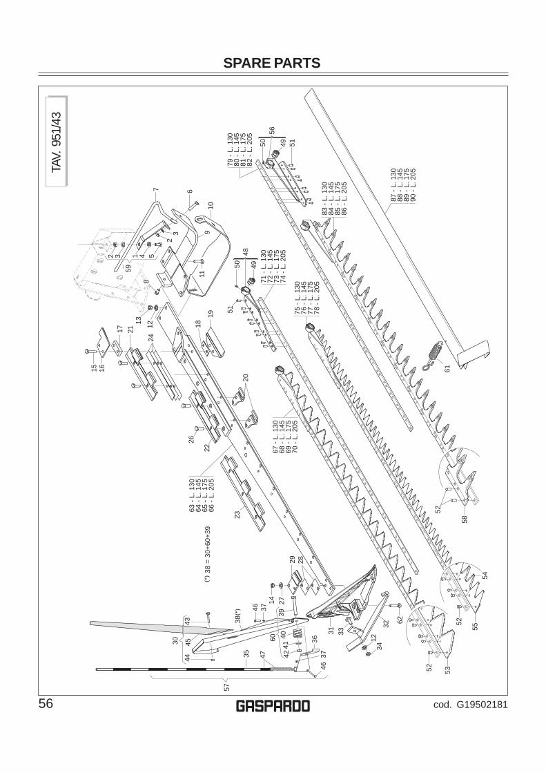
SPARE PARTS
56 cod. G19502181g
TAV.
951
/43
67 -
L. 1
3068
- L.
145
69 -
L. 1
7570
- L.
205
75 -
L. 1
3076
- L.
145
77 -
L. 1
7578
- L.
205
63 -
L. 1
3064
- L.
145
65 -
L. 1
7566
- L.
205
5150 49
48
71 -
L. 1
3072
- L.
145
73 -
L. 1
7574
- L.
205
525352
5554
1 432 57
32
59
8
9
6
1011
5150 49
79 -
L. 1
3080
- L.
145
81 -
L. 1
7582
- L.
205
56
83 -
L. 1
3084
- L.
145
85 -
L. 1
7586
- L.
205
58
52
87 -
L. 1
3088
- L.
145
89 -
L. 1
7590
- L.
205
61
29 28
30
27144735
3746
38
38 =
30+
60+3
9
57
4445
43
31 33
3637
46
6039
4041
42
23
1234
32 62
18
19
26
22
20
24
2117
13 12
15 16

SPARE PARTSPo
s.Co
d.D
escr
iptio
nPo
s.Co
d.D
escr
iptio
n
57cod. G19502181 g
1 2 3 4 5 6 7 8 9 10 11 12 13 14 15 16 17 18 19 20 21 22 23 24 25 26 27 28 29 30 31 32 33 34 35 36 37 38 39 40 41 42 43 44 45
TAV.
951
/43
CU
TTIN
G B
LAD
E (T
OO
TH R
IVET
ED)
G21
1203
21IN
NE
R S
LID
E S
PAC
ER
FB
940
F012
0027
0N
UT
M10
F014
3002
3W
AS
HE
R D
10 D
IN 6
798
D.IN
T.ZN
F014
1006
4W
AS
HE
R 1
0,5X
21F0
1020
472
BOLT
10X
25 5
739
8.G
GA
LVA
NIZ
ED
F010
6007
7BO
LT 1
0X45
573
2 4.
8 G
ALV
AN
IZE
DG
2112
0322
HIN
GE
PR
OTE
CTI
ON
FB
940
F010
2047
0BO
LT M
10X
20G
2112
0323
INTE
RN
AL
RU
NN
ER
FB
940
G21
1203
24R
UN
NE
R W
IDE
INT.
SLI
DE
FB
940
F010
2015
4BO
LT 1
2X45
573
7 8.
G G
ALV
AN
IZE
DF0
1430
071
WA
SH
ER
D12
DIN
679
8 D
.INT.
ZNF0
1200
293
NU
T M
12F0
1220
233
NU
T TR
ISTO
P M
10F0
1020
112
BOLT
10X
45 5
737
8.G
GA
LVA
NIZ
ED
G21
1203
12U
PP
ER
INN
ER
BLA
DE
GU
IDE
FB
940
G21
1202
31SH
IMS
MM
.10
FB/S
G21
1200
44S
HIM
S- L
OW
ER
INT.
GU
IDE
G21
1200
45IN
NE
R L
OW
ER
BLA
DE
GU
IDE
G21
1200
42LO
WE
R B
LAD
E G
UID
EG
1920
2331
UP
PE
R IN
TER
NA
L B
LAD
E G
UID
EG
1920
2341
UP
PE
R B
LAD
E G
UID
EG
1301
5581
UP
PE
R E
ST.
BLA
DE
GU
IDE
1,3
0G
2112
0320
SH
IMS
- UP
PE
R B
LAD
E G
UID
EG
1301
0651
EX
TER
NA
L U
PP
ER
BLA
DE
GU
IDE
F010
2048
0S
CR
EW
10X
35 5
739
8.G
F014
1006
4W
AS
HE
R 1
0,5X
21G
2112
0040
SHIM
S M
M.1
UPP
ER E
XT. G
UID
EG
2112
0039
UP
PE
R O
UT.
BLA
DE
GU
IDE
G20
8000
61SW
ATH
BOAR
D R
OD
ASS
Y.G
1920
0903
OU
TER
BA
R S
UP
PO
RT
FBR
G21
1200
38EX
T. R
UN
NE
R S
LID
EF0
1030
508
BOLT
T.Q
. 11X
30F0
1200
281
NU
T 11
UN
I 558
8 6.
8G
1301
1640
IND
ICAT
ION
BAR
G13
0116
50IN
DIC
ATIO
N B
AR S
UPP
OR
TF0
1230
016
NO
RM
.SEL
F-LO
CKI
NG
NU
T 4
GAL
VAN
G21
1201
34SW
ATH
BOAR
D - A
SSY.
FB
F010
6010
5BO
LT 1
2X80
573
2 4.
6 G
ALV
AN
IZE
DG
6533
8001
ZN S
WAT
HBO
ARD
CO
MP.
SPR
ING
. F
F014
1007
6P
LAN
E W
AS
HE
R D
.12
F012
3005
8S
ELF
LO
CK
ING
NU
T M
12X
1,25
F010
6004
5BO
LT 8
X40
573
2 4.
6 G
ALV
AN
IZE
DF0
1230
034
SE
LF L
OC
KIN
G N
UT
M8X
1,25
G20
8000
61SW
ATH
BOAR
D R
OD
ASS
Y.
46 47 48 49 50 51 52 53 54 55 56 57 58 59 60 61 62 63 64 65 66 67 68 69 70 71 72 73 74 75 76 77 78 79 80 81 82 83 84 85 86 87 88 89 90
F010
2001
1S
CR
EW
4X
35 5
737
8.G
ZN
G13
0116
60IN
DIC
ATIN
BAR
G13
0115
50IN
TER
NA
L S
EC
TIO
N B
LAD
EH
EA
DG
2112
0048
BU
SH
ING
- BLA
DE
HE
AD
28X
20X
24F0
1100
011
SPH
ERE
NIP
PLE
M6X
1/A
F022
5052
0PA
CK
BLA
D.M
OU
NT.
TSC
6 X
19-8
KG
F022
5051
9PA
CK
BLAD
.MO
UN
T.TS
C 6
X13
-8G
2112
0243
CU
T S
EC
TIO
N F
B/S
G13
0135
50LO
WE
R D
OU
BLE
PO
INT
SE
CTI
ON
G13
0135
40U
PP
ER
DO
UB
LE P
OIN
T S
EC
TIO
NG
1301
1590
EXT.
CO
MPL
ETE
TOO
TH B
LAD
EHEA
DG
2112
0134
SWAT
HBO
ARD
- ASS
Y. F
BG
1301
3810
SPEC
IAL
TOO
THG
1301
3120
CO
MPL
ETE
SPAC
ERG
2112
0133
SWAT
HBO
ARD
BO
LT A
SSY.
FB
G65
3370
02TR
ACTI
ON
SPR
ING
GU
ARD
FS
F010
3050
1S
CR
EW
TS
QS
T 10
X45
8.8
G21
1203
13B
AR
MT.
1.3
0 FB
940
G21
1203
14B
AR
MT.
1.4
5 FB
940
G21
1203
15R
EIN
FOR
CE
D B
AR
MT.
1.7
5 FB
940
G21
1203
16R
EIN
FOR
CE
D B
AR
MT.
2.0
5 FB
940
G21
1202
38C
UTT
ING
BLA
DE
MT.
1-30
FB
/SG
2112
0239
CU
TTIN
G B
LAD
E M
T.1-
45 F
B/S
G21
1202
40C
UTT
ING
BLA
DE
MT.
1-75
FB
/SG
2112
0241
CU
TTIN
G B
LAD
E M
T.2-
05 F
B/S
G21
1202
44R
OD
SE
CTI
ON
S M
T. 1
.30
FB/S
G21
1202
45R
OD
SE
CTI
ON
S M
T. 1
.45
FB/S
G21
1202
46R
OD
SE
CTI
ON
S M
T. 1
.75
FB/S
G21
1202
47R
OD
SE
CTI
ON
S M
T. 2
.05
FB/S
G13
0136
00D
OU
BLE
-TIP
SE
CTI
ON
BLA
DE
1.3
0G
1301
3610
DO
UB
LE-T
IP S
EC
TIO
N B
LAD
E 1
.45
G13
0136
20D
OU
BLE
-TIP
SE
CTI
ON
BLA
DE
1.7
5G
1301
3630
DO
UB
LE E
DG
ED
BLA
DE
GU
IDE
SE
CT
G21
1202
49B
LAD
E R
OD
- MT.
1.3
0 FB
/SG
2112
0250
BLA
DE
RO
D- M
T. 1
.45
FB/S
G21
1202
51B
LAD
E R
OD
- MT.
1.7
5 FB
/SG
2112
0252
BLA
DE
RO
D- M
T. 2
.05
FB/S
G13
0138
40C
OM
PL. R
EMV.
-TO
OTH
ED B
LAD
E FB
RG
1301
3850
CO
MPL
. REM
V.-T
OO
THED
BLA
DE
FBR
G13
0138
60C
OM
PL. R
EMV.
-TO
OTH
ED B
LAD
E FB
RG
1301
3870
CO
MPL
. REM
V.-T
OO
THED
BLA
DE
FBR
G21
1201
07P
RO
TEC
TIO
N S
HIE
LD 1
.30M
G21
1200
63P
RO
TEC
TIO
N S
HIE
LD 1
.45M
G21
1200
54G
UA
RD
- P
RO
TEC
TIO
N M
T.1-
75G
2112
0112
CO
MPL
ETE
PRO
TEC
TIO
N M
T 2,
05

SPARE PARTS
58 cod. G19502181g
TAV.
951
/53
71 -
L. 1
3072
- L.
145
73 -
L. 1
7574
- L.
205
95 -
L. 1
3096
- L.
145
97 -
L. 1
7598
- L.
205
61
91 -
L. 1
3092
- L.
145
93 -
L. 1
7594
- L.
205
79 -
L. 1
3080
- L.
145
81 -
L. 1
7582
- L.
205
67 -
L. 1
3068
- L.
145
69 -
L. 1
7570
- L.
205
5750 49
83 -
L. 1
3084
- L.
145
85 -
L. 1
7586
- L.
205
87 -
L. 1
3088
- L.
145
89 -
L. 1
7590
- L.
205
5150 49
48
75 -
L. 1
3076
- L.
145
77 -
L. 1
7578
- L.
205
56
6643
4445
65
38 =
64+
66+3
8
3538
47
2726
25233746
2829
30
14
3736
46
64 4027
4142
39
12
15 16
18 17 21
26 27
1918
20
22
33
62
31
3234
24
13 128 11
32 1 4 5
23
7 6
109
525352
5554
58
5960
63

SPARE PARTSPo
s.Co
d.D
escr
iptio
nPo
s.Co
d.D
escr
iptio
n
59cod. G19502181 g
1 2 3 4 5 6 7 8 9 10 11 12 13 14 15 16 17 18 19 20 21 22 23 24 25 26 27 28 29 30 31 32 33 34 35 36 37 38 39 40 41 42 43 44 45 46 47 48 49
G21
1203
21IN
NE
R S
LID
E S
PAC
ER
FB
940
F012
0027
0N
UT
M10
F014
3002
3W
AS
HE
R D
10 D
IN 6
798
D.IN
T.ZN
F014
1006
4W
AS
HE
R 1
0,5X
21F0
1020
472
BOLT
10X
25 5
739
8.G
GA
LVA
NIZ
ED
F010
6007
7BO
LT 1
0X45
573
2 4.
8 G
ALV
AN
IZE
DG
2112
0322
HIN
GE
PR
OTE
CTI
ON
FB
940
F010
2047
0BO
LT M
10X
20G
2112
0323
INTE
RN
AL
RU
NN
ER
FB
940
G21
1203
24R
UN
NE
R W
IDE
INT.
SLI
DE
FB
940
F010
2015
4BO
LT 1
2X45
573
7 8.
G G
ALV
AN
IZE
DF0
1430
071
WA
SH
ER
D12
DIN
679
8 D
.INT.
ZNF0
1200
293
NU
T M
12F0
1220
233
NU
T TR
ISTO
P M
10F0
1020
114
BOLT
10X
50 5
737
8.G
GA
LVA
NIZ
ED
G21
1203
12U
PP
ER
INN
ER
BLA
DE
GU
IDE
FB
940
G13
0116
00IN
T. B
LAD
E G
UID
E S
UP
PO
RT
G21
1200
44S
HIM
S- L
OW
ER
INT.
GU
IDE
G21
1200
45IN
NE
R L
OW
ER
BLA
DE
GU
IDE
G13
0131
51LO
WE
R D
OU
BLE
BLA
DE
GU
IDE
G19
2033
11U
PPER
BLA
DE
INT.
GU
IDE
REM
OVA
BG
1920
3301
UPP
ER B
LAD
E G
UID
E R
EMO
VABL
E TI
G13
0115
01U
PPER
BLA
DE
GU
IDE
EXT.
REM
OVA
BG
1301
1510
SH
IM F
OR
UP
PE
R B
LAD
E G
UID
EG
1301
1520
UP
PE
R E
XT.
BLA
DE
GU
IDE
SH
IMF0
1020
480
SC
RE
W 1
0X35
573
9 8.
GF0
1410
064
WA
SH
ER
10,
5X21
G21
1200
40SH
IMS
MM
.1 U
PPER
EXT
. GU
IDE
G21
1200
39U
PP
ER
OU
T. B
LAD
E G
UID
EG
1301
3511
LOW
ER
SIN
GLE
BLA
DE
GU
IDE
G19
2009
03O
UTE
R B
AR
SU
PP
OR
T FB
RG
2112
0038
EXT.
RU
NN
ER
SLI
DE
F010
3050
8BO
LT T
.Q. 1
1X30
F012
0028
1N
UT
11 U
NI 5
588
6.8
G13
0116
40IN
DIC
ATIO
N B
ARG
1301
1650
IND
ICAT
ION
BAR
SU
PPO
RT
F012
3001
6N
OR
M.S
ELF-
LOC
KIN
G N
UT
4 G
ALVA
NG
2112
0134
SWAT
HBO
ARD
- ASS
Y. F
BF0
1060
105
BOLT
12X
80 5
732
4.6
GA
LVA
NIZ
ED
G65
3380
01ZN
SW
ATH
BOAR
D C
OM
P. S
PRIN
G .
FF0
1410
076
PLA
NE
WA
SH
ER
D.1
2F0
1230
058
SE
LF L
OC
KIN
G N
UT
M12
X1,
25F0
1060
045
BOLT
8X
40 5
732
4.6
GA
LVA
NIZ
ED
F012
3003
4S
ELF
LO
CK
ING
NU
T M
8X1,
25G
2080
0061
SWAT
HBO
ARD
RO
D A
SSY.
F010
2001
1S
CR
EW
4X
35 5
737
8.G
ZN
G13
0116
60IN
DIC
ATIN
BAR
G13
0131
90C
OM
PL. B
LAD
E H
EAD
SEC
TIO
NS
G21
1200
48B
US
HIN
G- B
LAD
E H
EA
D 2
8X20
X24
TAV.
951
/53
CU
TTIN
G B
LAD
E (R
EPLA
CEA
BLE
TO
OTH
)
50 51 52 53 54 55 56 57 58 59 60 61 62 63 64 65 66 67 68 69 70 71 72 73 74 75 76 77 78 79 80 81 82 83 84 85 86 87 88 89 90 91 92 93 94 95 96 97 98
F011
0001
1SP
HER
E N
IPPL
E M
6X1/
AF0
2250
520
PAC
K B
LAD
.MO
UN
T.TS
C 6
X19
-8 K
GF0
2250
519
PAC
K BL
AD.M
OU
NT.
TSC
6 X
13-8
G21
1202
43C
UT
SE
CTI
ON
FB
/SG
1301
3550
LOW
ER
DO
UB
LE P
OIN
T S
EC
TIO
NG
1301
3540
UP
PE
R D
OU
BLE
PO
INT
SE
CTI
ON
G13
0132
30C
OM
PL. B
LAD
E H
EAD
w/ R
EMV.
TEE
F022
5052
0PA
CK
BLA
D.M
OU
NT.
TSC
6 X
19-8
KG
G13
0138
30SP
ECIA
L R
EMO
VABL
E TE
ETH
F010
1022
2S
CR
EW
8X
1X12
574
0 10
.9F0
1460
138
CO
NTA
CT
ELA
ST.
WA
SH
ER
D8
G65
3370
02TR
ACTI
ON
SPR
ING
GU
ARD
FS
F010
3050
1S
CR
EW
TS
QS
T 10
X45
8.8
G13
0131
20C
OM
PLET
E SP
ACER
G21
1201
33SW
ATH
BOAR
D B
OLT
ASS
Y. F
BG
2112
0134
SWAT
HBO
ARD
- ASS
Y. F
BG
2080
0061
SWAT
HBO
ARD
RO
D A
SSY.
G13
0133
90R
EMV.
TO
OTH
-HO
LDIN
G B
AR 1
.30
G13
0134
10R
EMV.
TO
OTH
-HO
LDIN
G B
AR 1
.45
G13
0134
31R
EMV.
TO
OTH
-HO
LDIN
G B
AR 1
.75
G13
0134
71R
EMV.
TO
OTH
-HO
LDIN
G B
AR 2
.05
G13
0135
60C
OM
PL.
SE
CTI
ON
-HO
LDIN
G B
AR
1.3
G13
0135
70C
OM
PL.
SE
CTI
ON
-HO
LDIN
G B
AR
1.4
G13
0135
80C
OM
PL.
SE
CTI
ON
-HO
LDIN
G B
AR
1.7
G13
0135
90C
OM
PL.
SE
CTI
ON
-HO
LDIN
G B
AR
2.0
G21
1202
44R
OD
SE
CTI
ON
S M
T. 1
.30
FB/S
G21
1202
45R
OD
SE
CTI
ON
S M
T. 1
.45
FB/S
G21
1202
46R
OD
SE
CTI
ON
S M
T. 1
.75
FB/S
G21
1202
47R
OD
SE
CTI
ON
S M
T. 2
.05
FB/S
G13
0136
50D
OU
BLE
-TIP
SE
CTI
ON
BLA
DE
R.T
1G
1301
3660
DO
UB
LE-T
IP S
EC
TIO
N B
LAD
E R
.T 1
G13
0136
70D
OU
BLE
-TIP
SE
CTI
ON
BLA
DE
R.T
1G
1301
3680
DO
UB
LE S
EC
TIO
N B
LAD
E G
UID
E P
.DG
1301
3751
CO
MPL
. REM
V.-T
OO
THED
BLA
DE
FBR
G13
0137
61C
OM
PL. R
EMV.
-TO
OTH
ED B
LAD
E FB
RG
1301
3770
CO
MPL
. REM
V.-T
OO
THED
BLA
DE
FBR
G13
0137
80C
OM
PL. R
EMV.
-TO
OTH
ED B
LAD
E FB
RG
1301
3280
REM
V. T
OO
TH-H
OLD
ING
BAR
1.3
0G
1301
3290
REM
V. T
OO
TH-H
OLD
ING
BAR
1.4
5G
1301
3300
REM
V. T
OO
TH-H
OLD
ING
BAR
1.7
5G
1301
3310
REM
V. T
OO
TH-H
OLD
ING
BAR
2.0
5G
1301
3751
CO
MPL
. REM
V.-T
OO
THED
BLA
DE
FBR
G13
0137
61C
OM
PL. R
EMV.
-TO
OTH
ED B
LAD
E FB
RG
1301
3771
CO
MPL
. REM
V.-T
OO
THED
BLA
DE
FBR
G13
0137
81C
OM
PL. R
EMV.
-TO
OTH
ED B
LAD
E FB
RG
2112
0107
PR
OTE
CTI
ON
SH
IELD
1.3
0MG
2112
0063
PR
OTE
CTI
ON
SH
IELD
1.4
5MG
2112
0054
GU
AR
D -
PR
OTE
CTI
ON
MT.
1-75
G21
1201
12C
OM
PLET
E PR
OTE
CTI
ON
MT
2,05
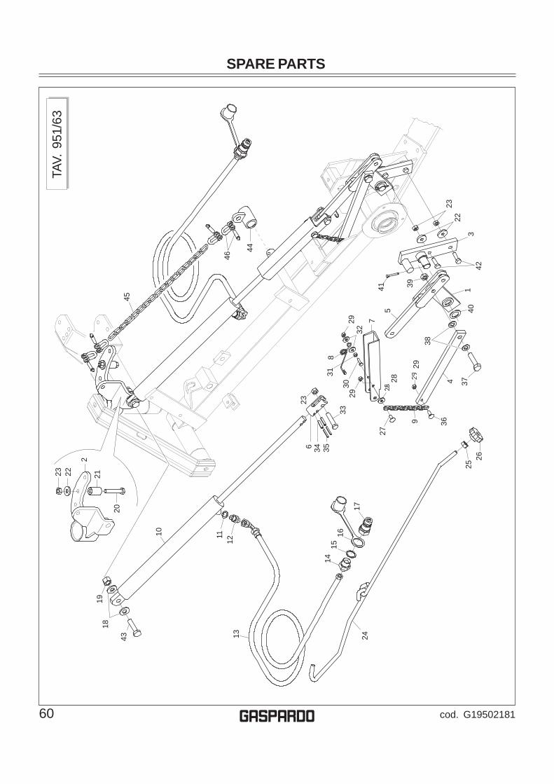
SPARE PARTS
60 cod. G19502181g
TAV.
951
/63
10 11
43
1819
1213 24
1415
16
17
2526
369
2728
29
4
2930
3133
3534623
8
732
29
541 39
401
42
37
38
2322
3
46
44
20
21
2
2223
45

SPARE PARTSPo
s.Co
d.D
escr
iptio
nPo
s.Co
d.D
escr
iptio
n
61cod. G19502181 g
1 2 3 4 5 6 7 8 9 10 11 12 13 14 15 16 17 18 19 20 21 22 23 24 25 26 27 28 29 30 31 32 33 34 35 36
G12
2178
80LI
FTIN
G R
OD
G12
2180
70C
YLIN
DER
LIN
KAG
E D
EVIC
EG
1221
7860
LIFT
ING
PLA
TEG
1221
7910
LIFT
ING
AR
TIC
ULA
TIO
N B
ARG
1221
7900
FOR
K L
EV
ER
CO
NN
EC
TIO
NG
1221
6820
CY
LIN
DE
R C
OU
PLI
NG
G12
2179
20LI
FTIN
G B
AR E
DG
EG
1890
3780
UP
PE
R H
OO
K T
OR
SIO
N S
PR
ING
G12
2179
30C
HA
IN D
.5 L
.194
G21
2100
02C
YLI
ND
ER
D.4
0-D
.20-
380
F031
5123
81/
4 C
OP
PE
R W
AS
HE
RG
1601
1690
UP
RIG
HT
1/4'
' NIP
PLE
WIT
H G
RU
BG
2344
0517
PIP
E 1
/4R
2 C
-F 1
/4 L
2000
HL/
IDF0
3150
211
NIP
LE 1
/4-1
/2F0
3151
237
1/2
CO
PP
ER
WA
SH
ER
F051
5032
5C
OV
ER
1/2
F031
5093
5Q
UIC
K C
ON
NE
CT
MA
LE C
ON
E 1
/2 C
OG
2097
0111
WAS
HER
29,
8X2X
16,5
F012
3008
4S
ELF
LO
CK
ING
NU
T M
16X
1,5
F010
2016
6BO
LT 1
2X80
573
7 8.
G G
ALV
AN
IZE
DG
1880
2150
BO
SH
ING
12,
3X25
X42
G20
9700
85W
ASH
ER 4
0X4X
13F0
1230
058
SE
LF L
OC
KIN
G N
UT
M12
X1,
25G
1221
7450
BLA
DE
TIE
RO
D Z
NF0
1200
306
NU
T M
14X2
F062
2001
16-
LOB
E H
AN
DW
HE
EL
M14
F010
6004
0BO
LT 8
X20
573
2 4.
6 G
ALV
AN
IZE
DG
2097
0104
WAS
HER
21X
4X8-
5F0
1220
222
NU
T- T
RIS
TOP
M 8
F010
2044
1S
CR
EW
8 X
25 5
739
8.G
F012
0024
4N
UT
M8
F014
2004
8P
LAN
E W
AS
HE
R D
.8F0
1020
162
BOLT
M 1
2X65
F021
0014
1P
IN E
L. 8
X36
DIN
148
1F0
2100
089
PIN
EL.
5 X
36 D
IN 1
481
F010
6004
1BO
LT 8
X25
573
2 4.
6 G
ALV
AN
IZE
D
37 38 39 40 41 42 43 44 45 46
F010
2020
7BO
LT M
14X
70F0
1410
088
PLA
NE
WA
SH
ER
D.1
4F0
1230
072
SE
LF L
OC
KIN
G N
UT
M14
X1,
5G
2097
0070
WAS
HER
40X
2X26
F022
0022
8S
PLI
T P
IN 5
X35
133
6 G
ALV
AN
.F0
1020
152
BOLT
M 1
2X40
F010
2026
0BO
LT M
16X2
X70
G12
2180
30TI
E-R
OD
BU
SH
G21
1200
07A
RM
SID
E C
HA
IN L
.600
F022
5066
7C
LEVI
S- 3
/8- G
ALVA
NIS
ED- A
RT.TA
V. 9
51/6
3H
YDR
AU
LIC
LIF
TIN
G S
YSTE
M

WARRANTY
62 cod. G19502181g
WARRANTY
GASPARDO warrants this product to be free from defect in material and workmanship. Except as otherwise set forth below, theduration of this Warranty shall be for TWELVE (12) MONTHS COMMENCING ON THE DATE OF DELIVERY OF THE PRODUCTTO THE ORIGINAL PURCHASER.
Under no circumstances wilI this Warranty apply in the event that the product, in the good faith opinion of GASPARDO, hasbeensubjected to improper operation, improper maintenance, misuse, or an accident. This Warranty does not apply in the event thatthe product has been materially modified or repaired by someone other than GASPARDO, a GASPARDO authorized dealer ordistributor, and/or a GASPARDO authorized service center. This Warranty does not cover normal wear or tear, or normalmaintenance items. This Warranty also does not cover repairs made with parts other than those obtainable through GASPARDO.
This Warranty is extended solely to the original purchaser of the product. Should the original purchaser sell or otherwisetransfer this product to a third party, this Warranty does not transfer to the third party purchaser in any way. There are no thirdparty beneficiaries of this Warranty.
GASPARDO makes no warranty, express or implied, with respect to engines, batteries, tires or other parts or accessories notmanufactured by FRONTIER. Warranties for these items, if any, are provided separately by their respective manufacturers.
GASPARDO’ obligation under this Warranty is limited to, at GASPARDO’ option, the repair or replacement, free of charge, of theproduct if GASPARDO, in its sole discretion, deems it to be defective or in noncompliance with this Warranty. The product mustbe returned to GASPARDO S.p.A. with proof of purchase within thirty (30) days after such defect or noncompliance isdiscovered or should have been discovered, routed through the dealer and distributor from whom the purchase was made,transportation charges prepaid. GASPARDO shall complete such repair or replacement within a reasonable time after GASPARDOreceives the product.THERE ARE NO OTHER REMEDIES UNDER THIS WARRANTY. THE REMEDY OF REPAIR OR REPLACEMENT IS THESOLE AND EXCLUSIVE REMEDY UNDER THIS WARRANTY.
THERE ARE NO WARRANTIES WHICH EXTEND BEYOND THE DESCRIPTION ON THE FACE OF THIS WARRANTY.GASPARDO MAKES NO OTHER WARRANTY, EXPRESS OR IMPLIED, AND GASPARDO SPECIFICALLY DISCLAIMS ANYIMPLIED WARRANTY OF MERCHANTABILITY AND/OR ANY IMPLIED WARRANTY OF FITNESS FOR A PARTICULARPURPOSE.
GASPARDO shall not be liable for any incidental or consequential losses, damages or expenses, arising directly or indirectlyfrom the product, whether such claim is based upon breach of contract, breach of warranty, negligence, strict liability in tortor any other legal theory. Without limiting the generality of the foregoing, GASPARDO specifically disclaims any damagesrelating to (i) lost profits, business, revenues or goodwill; (ii) loss of crops; (iii) loss because of delay in harvesting; (iv) anyexpense or loss incurred for labor, supplies, substitute machinery or rental; or (v) any other type of damage to property oreconomic loss.
This Warranty is subject to any existing conditions of supply which may directly affect GASPARDO’ ability to obtain materialsor manufacture replacement parts.
No agent, representative, dealer, distributor, serviceperson, salesperson, or employee of any company, including withoutlimitation, GASPARDO, its authorized dealers, distributors, and service centers, is authorized to alter, modity, or enlarge thisWarranty.
This Warranty is effective only if the warranty registration is returned within ten (10) days.
For warranty services contact your selling dealer.
GGGGG

WARRANTY
63cod. G19502181 g
WARRANTY FOR REPLACEMENT PARTS
GASPARDO warrants this product to be free from defect in material and workmanship for a period of ninety (90) days from thedate of delivery of the product to the original purchaser.
Under no circumstances will this Warranty apply in the event that the product, in the good faith opinion of GASPARDO, hasbeen subjected to improper operation, improper maintenance, misuse, or an accident. This Warranty does not cover normal wearor tear, or normal maintenance items.
This Warranty is extended solely to the original purchaser of the product. Should the original purchaser sell or otherwisetransfer this product to a third party, this Warranty does not transfer to the third party purchaser in any way. There are no thirdparty beneficiaries of this Warranty.
GASPARDO’ obligation under this Warranty is limited to, at GASPARDO’ option, the repair or replacement, free of charge, of theproduct if GASPARDO, in its sole discretion, deems it to be defective or in noncompliance with this Warranty. The product mustbe returned to GASPARDO with proof of purchase within thirty (30) days after such defect or noncompliance is discovered orshould have been discovered, routed through the dealer and distributor from whom the purchase was made, transportationcharges prepaid. GASPARDO shall complete such repair or replacement within a reasonable time after GASPARDO receives theproduct. THERE ARE NO OTHER REMEDIES UNDER THIS WARRANTY THE REMEDY OF REPAIR OR REPLACEMENT ISTHE SOLE AND EXCLUSIVE REMEDY UNDER THIS WARRANTY.
THERE ARE NO WARRANTIES WHICH EXTEND BEYOND THE DESCRIPTION ON THE FACE OF THIS WARRANTY.GASPARDO MAKES NO OTHER WARRANTY, EXPRESS OR IMPLIED, AND GASPARDO SPECIFICALLY DISCLAIMS ANYIMPLIED WARRANTY OF MERCHANTABILITY AND/OR ANY IMPLIED WARRANTY OF FITNESS FOR A PARTICULARPURPOSE.
GASPARDO shall not be liable for any incidental or consequential losses, damages or expenses, arising directly or indirectlyfrom the product, whether such claim is based upon breach of contract, breach of warranty, negligence, strict liability in tortor any other legal theory. Without limiting the generality of the foregoing, GASPARDO specifically disclaims any damagesrelating to (i) lost profits, business, revenues or goodwill; (ii) loss of crops; (iii) loss because of delay in harvesting; (iv) anyexpense or lossincurred for labor, supplies, substitute machinery or rental; or (v) any other type of damage to property or economic loss.
This Warranty is subject to any existing conditions of supply which may directly affect GASPARDO’ ability to obtain materialsor manufacture replacement parts.
No agent, representative, dealer, distributor, service person, salesperson, or employee of any company, including withoutlimitation, GASPARDO, its authorized dealers, distributors, and service centers, is authorized to alter, modify, or enlarge thisWarranty.
For warranty services contact your selling dealer.
GGGGG

NOTES
64 cod. G19502181g

NOTES
65cod. G19502181 g

ALWAYS USE ORIGINAL SPARE PARTS
G19502181*G19502181*
DEALER:
g
Ufficio Tecnico GASPARDO Seminatrici S.p.A.
gGASPARDO Seminatrici SpAVia Mussons, 7 - I - 33075Morsano al Tagliamento (PN) ItalyTel. +39 0434 695410Fax +39 0434 695425e-mail: [email protected]://www.gaspardo.it
MASCHIO DEUTSCHLAND GMBHÄußere Nürmberger Straße 5D - 91177 ThalmässingDeutschlandTel. +49 (0) 9173 79000Fax +49 (0) 9173 790079
MASCHIO FRANCE Sarl1, Rue de Mérignan ZAF - 45240 La Ferte St. AubinFranceTel. +33 (0) 2.38.64.12.12Fax +33 (0) 2.38.64.66.79
MASCHIO IBERICA S.L.Calle Cabernet, 10Poligono Industrial Clot de MojaOlerdola - 08734 BarcelonaTel. +34 93.81.99.058Fax +34 93.81.99.059
MASCHIO USA432 2ND StreetRock Island, IL 612Ø1 USAPh. +1 309 794-2310Fax +1 309 788-1610
MASCHIO MIDDLE EAST S.LMASCHIO-GASPARDO ROMANIA S.R.L.GASPARDO-MASCHIO TURCHIAMASCHIO-GASPARDO CANADA Inc