Embed Size (px)
Citation preview


192 Chapter 19
ANSWERS TO MULTIPLE CHOICE QUESTIONS
1. The electron moves in a horizontal plane in a direction of 35° N or E, which is the same as 55° E of N. Since the magnetic fi eld at this location is horizontal and directed due north, the angle between the direction of the electron’s velocity and the direction of the magnetic fi eld is 55°. The magnitude of the magnetic force experienced by the electron is then
F q B= = "( ) "( ) "! !v sin . . .& 1 6 10 2 5 10 0 10 1019 6 C m s 44 1855 3 3 10 T N( ) = " !sin .°
The right-hand rule number 1 predicts a force directed upward, away from the Earth’s surface for a positively charged particle moving in the direction of the electron. However, the negatively charged electron will experience a force in the opposite direction, downward toward the Earth’s surface. Thus, the correct choice is (d).
2. If the magnitude of the magnetic force on the wire equals the weight of the wire, then BI wl sin& = , or B w I= l sin& . The magnitude of the magnetic fi eld is a minimum when & &= =90 1° and sin . Thus,
B
wImin
..
.= = "( )( ) =
!
l
1 0 100 50
0 202 N
0.10 A m T
and (a) is the correct answer for this question.
3. The z-axis is perpendicular to the plane of the loop, and the angle between the direction of this normal line and the direction of the magnetic fi eld is & = 30 0. °. Thus, the magnitude of the torque experienced by this coil containing N = 10 turns is
( &= = ( )( ) ( )( )BIAN sin . . . .0 010 2 0 0 20 0 30 T A m m))* +,( ) = " -!10 30 0 6 0 10 3sin . .° N m
meaning that (c) is the correct choice.
4. A charged particle moving perpendicular to a magnetic fi eld experiences a centripetal force of magnitude F m r q Bc = =v v2 and follows a circular path of radius r m qB= v . The speed of this proton must be
v = =
"( )( ) "( )! !qBrm
1 6 10 0 050 1 0 10
1
19 3. . .
.
C T m
667 104 8 1027
3
"= "! kg
m s.
and choice (e) is the correct answer.
5. The magnitude of the magnetic fi eld at distance r from a long straight wire carrying current I is B I r= µ #0 2 . Thus, for the described situation,
B =
" -( )( )( ) = "
!!4 10 1
2 21 10
77
##
T m A A
m T
/
making (d) the correct response.
6. The force per unit length between this pair of wires is
F I Idl
= =" -( )( )
( ) = "!µ
##
#0 1 2
7
2
4 10 3
2 29
T m A A
m
2
110 1 107 6! !" N N.
and (d) is the best choice for this question.
7. The magnitude of the magnetic fi eld inside the specifi ed solenoid is
B nI
NI= = /
01234 = " -( )/!µ µ #0 0
74 10120
0 50l T m A
m.001234 ( ) = " !2 0 6 0 10 4. . A T
which is choice (e).
56157_19_ch19_p171-218.indd 19256157_19_ch19_p171-218.indd 192 3/18/08 11:39:38 PM3/18/08 11:39:38 PM

Magnetism 193
8. The magnitude of the magnetic force experienced by a charged particle in a magnetic fi eld is given by F q B= v sin& , where v is the speed of the particle and & is the angle between the direc-tion of the particle’s velocity and the direction of the magnetic fi eld. If either v = 0 [choice (e)] or sin& = 0 [choice (c)], this force has zero magnitude. All other choices are false, so the correct answers are (c) and (e).
9. The force that a magnetic fi eld exerts on a moving charge is always perpendicular to both the direction of the fi eld and the direction of the particle’s motion. Since the force is perpendicular to the direction of motion, it does no work on the particle and hence does not alter its speed. Because the speed is unchanged, both the kinetic energy and the magnitude of the linear momen-tum will be constant. Correct answers among the list of choices are (d) and (e). All other choices are false.
10. By the right-hand rule number 1, when the proton fi rst enters the fi eld, it experiences a force directed upward, toward the top of the page. This will defl ect the proton upward, and as the proton’s velocity changes direction, the force changes direction always staying perpendicular to the velocity. The force, being perpendicular to the motion, causes the particle to follow a circu-lar path, with no change in speed, as long as it is in the fi eld. After completing a half circle, the proton will exit the fi eld traveling toward the left. The correct answer is choice (d).
11. The contribution made to the magnetic fi eld at point P by the lower wire is directed out of the page, while the contribution due to the upper wire is directed into the page. Since point P is equi-distant from the two wires, and the wires carry the same magnitude currents, these two oppositely directed contributions to the magnetic fi eld have equal magnitudes and cancel each other. There-fore, the total magnetic fi eld at point P is zero, making (a) the correct answer for this question.
12. The magnetic fi eld due to the current in the vertical wire is directed into the page on the right side of the wire and out of the page on the left side. The fi eld due to the current in the horizontal wire is out of the page above this wire and into the page below the wire. Thus, the two contributions to the total magnetic fi eld have the same directions at points B (both out of the page) and D (both contributions into the page), while the two contributions have opposite directions at points A and C. The magnitude of the total magnetic fi eld will be greatest at points B and D where the two contributions are in the same direction, and smallest at points A and C where the two contribu-tions are in opposite directions and tend to cancel. The correct choices for this question are (a) and (c).
13. Any point in region I is closer to the upper wire which carries the larger current. At all points in this region, the outward directed fi eld due the upper wire will have a greater magnitude than will the inward directed fi eld due to the lower wire. Thus, the resultant fi eld in region I will be nonzero and out of the page, meaning that choice (d) is a true statement and choice (a) is false. In region II, the fi eld due to each wire is directed into the page, so their magnitudes add and the resultant fi eld cannot be zero at any point in this region. This means that choice (b) is false. In region III, the fi eld due to the upper wire is directed into the page while that due to the lower wire is out of the page. Since points in this region are closer to the wire carrying the smaller current, there are points in this region where the magnitudes of the oppositely directed fi elds due to the two wires will have equal magnitudes, canceling each other and producing a zero resultant fi eld. Thus, choice (c) is true and choice (e) is false. The correct answers for this question are choices (c) and (d).
14. The torque exerted on a single turn coil carrying current I by a magnetic fi eld B is ( &= BIA sin . The line perpendicular to the plane of each coil is also perpendicular to the direction of the magnetic fi eld (i.e., & = 90°). Since B and I are the same for all three coils, the torques exerted on them are proportional to the area A enclosed by each of the coils. Coil A is rectangular with area AA
2 m m m= ( )( ) =1 2 2 . Coil B is elliptical with semi-major axis a = 0 75. m and
56157_19_ch19_p171-218.indd 19356157_19_ch19_p171-218.indd 193 3/18/08 11:39:39 PM3/18/08 11:39:39 PM

194 Chapter 19
semi-minor axis b = 0 5. m, giving an area A abB = # or AB2 m m m= ( )( ) =# 0 75 0 5 1 2. . . .
Coil C is triangular with area A base heightC = ( )( )12
, or AC2 m m m= ( )( ) =1
21 3 1 5. . Thus,
A A AA C B> > , meaning that ( ( (A C B> > and choice (b) is the correct answer.
15. According to right-hand rule number 2, the magnetic fi eld at point P due to the current in the wire is directed out of the page, meaning that choices (c) and (e) are false. The magnitude of this fi eld is given by B I r= µ #0 2 , so choices (b) and (d) are false. Choice (a) is correct about both the magnitude and direction of the fi eld and is the correct answer for the question.
16. The magnetic fi eld inside a solenoid, carrying current I, with N turns and length L, is
B nINL
I= = /01
234µ µ0 0 . Thus, B
N ILA = µ0 A
A
, BN IL
BBA
AA= =µ0
212
, and BN I
LBC
A
AA= ( ) =
µ0 22
4 .
Therefore, we see that B B BC A B> > , and choice (d) gives the correct rankings.
ANSWERS TO EVEN NUMBERED CONCEPTUAL QUESTIONS
2. No. The force that a constant magnetic fi eld exerts on a charged particle is dependent on the velocity of that particle. If the particle has zero velocity, it will experience no magnetic force and cannot be set in motion by a constant magnetic fi eld.
4. Straight down toward the surface of Earth.
6. The magnet causes domain alignment in the iron such that the iron becomes magnetic and is attracted to the original magnet. Now that the iron is magnetic, it can produce an identical effect in another piece of iron.
8. The magnet produces domain alignment in the nail such that the nail is attracted to the magnet. Regardless of which pole is used, the alignment in the nail is such that it is attracted to the magnet.
10. No. The magnetic fi eld created by a single current loop resembles that of a bar magnet — strongest inside the loop, and decreasing in strength as you move away from the loop. Neither is the fi eld uniform in direction — the magnetic fi eld lines loop through the loop.
12. Near the poles the magnetic fi eld of Earth points almost straight downward (or straight upward), in the direction (or opposite to the direction) the charges are moving. As a result, there is little or no magnetic force exerted on the charged particles at the pole to defl ect them away from Earth.
14. The loop can be mounted on an axle that can rotate. The current loop will rotate when placed in an external magnetic fi eld for some arbitrary orientation of the fi eld relative to the loop. As the current in the loop is increased, the torque on it will increase.
16. (a) The blue magnet experiences an upward magnetic force equal to its weight. The yellow magnet is repelled by the red magnets by a force whose magnitude equals the weight of the yellow magnet plus the magnitude of the reaction force exerted on this magnet by the blue magnet.
(b) The rods prevent motion to the side and prevent the magnets from rotating under their mutual torques. Its constraint changes unstable equilibrium into stable.
(c) Most likely, the disks are magnetized perpendicular to their fl at faces, making one face a north pole and the other a south pole. The yellow magnet has a pole on its lower face which
56157_19_ch19_p171-218.indd 19456157_19_ch19_p171-218.indd 194 3/18/08 11:39:40 PM3/18/08 11:39:40 PM

Magnetism 195
is the same as the pole on the upper faces of the red magnets. The pole on the lower face of the blue magnet is the same as that on the upper face of the yellow magnet.
(d) If the upper magnet were inverted the yellow and blue magnets would attract each other and stick fi rmly together. The yellow magnet would continue to be repelled by and fl oat above the red magnets.
PROBLEM SOLUTIONS
19.1 Consider a three-dimensional coordinate system with the xy plane in the plane of this page, the +x-direction toward the right edge of the page and the +y-direction toward the top of the page. Then, the z-axis is perpendicular to the page with the +z-direction being upward, out of the page. The magnetic fi eld is directed in the +x-direction, toward the right.
(a) When a proton (positively charged) moves in the +y-direction, the right-hand rule number 1 gives the direction of the magnetic force as into the page or in the !z-direction .
(b) With rv in the !y-direction, the right-hand rule number 1 gives the direction of the force
on the proton as out of the page, in the + -directionz .
(c) When the proton moves in the +x-direction, parallel to the magnetic fi eld, the magnitude of the magnetic force it experiences is F q B= ( ) =v sin 0 0° , or there is a zero force in this case .
19.2 (a) For a positively charged particle, the direction of the force is that predicted by the right-hand rule number one. These are:
(a") in plane of page and to left (b") into the page
(c") out of the page (d") in plane of page and toward the top
(e") into the page (f") out of the page
(b) For a negatively charged particle, the direction of the force is exactly opposite what the right-hand rule number 1 predicts for positive charges. Thus, the answers for part (b) are
reversed from those given in part (a) .
19.3 Since the particle is positively charged, use the right-hand rule number 1. In this case, start with the fi ngers of the right hand in the direction of
rv and the thumb pointing in the direction of
rF.
As you start closing the hand, the fi ngers point in the direction of rB after they have moved 90°.
The results are
(a) into the page (b) toward the right (c) toward bottom of page
19.4 Hold the right hand with the fi ngers in the direction of rv so that as you close your hand, the
fi ngers move toward the direction of rB. The thumb will point in the direction of the force (and
hence the defl ection) if the particle has a positive charge. The results are
(a) toward top of page (b) out of the page , since the charge is negative.
(c) # = ° $180 zero force (d) into the page
56157_19_ch19_p171-218.indd 19556157_19_ch19_p171-218.indd 195 3/19/08 3:38:30 AM3/19/08 3:38:30 AM

196 Chapter 19
19.5 (a) The proton experiences maximum force when it moves perpendicular to the magnetic fi eld, and the magnitude of this maximum force is
F q Bmax sin . .= = "( ) "( )!v 90 1 60 10 6 00 10 119 6° C m s .. .50 1 1 44 10 12 T N( )( ) = " !
(b) aFmp
maxmax .
.= = ""
= "!
!1 44 10
108 62
12 N1.67 kg27 11014 m s2
(c) Since the magnitude of the charge of an electron is the same as that of a proton, the force experienced by the electron would havee the same magnitude , but would be in the
opposite direction due to the negative charge of the electron. The acceleration of the elec-tron would be much greater than that of the proton because of the mass of the electron is much smaller.
19.6 From F q B= v sin&, the magnitude of the force is found to be
F = "( ) "( ) "( )! !1 60 10 6 2 10 50 0 1019 6 6. . . si C m s T nn . .90 0 4 96 10 17°( ) = " ! N
Using the right-hand rule (fi ngers point westward in direction of rv , so they move downward
toward the direction of Bur
as you close the hand, the thumb points southward. Thus, the direction of the force exerted on a proton (a positive charge) is toward the south .
19.7 The gravitational force is small enough to be ignored, so the magnetic force must supply the needed centripetal acceleration. Thus,
mr
q Bv
v2
90= sin °, or v = q B rm
where r RE= + = "1000 km 7.38 10 m6
v =
"( ) "( ) "( )! !1 60 10 4 00 10 7 38 10
1
19 8 6. . .
.
C T m
667 102 83 1027
7
"= "! kg
m s.
If rv is toward the west and
rB is northward,
rF will be directed downward as required.
19.8 The speed attained by the electron is found from 12
2m q Vv = ( )5 , or
v = ( ) =
"( )( )"
!
!2 2 1 60 10 2 400
9 11 10
19
31
e Vm5 .
.
C V
kg m s= "2 90 107.
(a) Maximum force occurs when the electron enters the region perpendicular to the fi eld.
F q Bmax
C m s
=
= "( ) "( )!
v sin
. .
90
1 60 10 2 90 10 119 7
°
.. .70 7 90 10 12 T N( ) = " !
(b) Minimum force occurs when the electron enters the region parallel to the fi eld.
F q Bmin = =v sin 0 0°
56157_19_ch19_p171-218.indd 19656157_19_ch19_p171-218.indd 196 3/18/08 11:39:41 PM3/18/08 11:39:41 PM
Magnetism 197
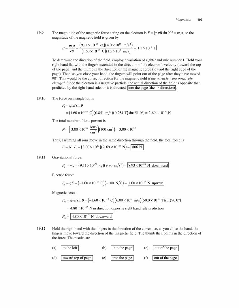
19.9 The magnitude of the magnetic force acting on the electron is F q B m ae= =v sin 90° , so the magnitude of the magnetic fi eld is given by
Bm ae
e= ="( ) "( )"
!
v9 11 10 4 0 10
1 60 1
31 16. .
.
kg m s2
00 1 5 101 5 10
19 72
!!
( ) "( ) = " C m s
T.
.
To determine the direction of the fi eld, employ a variation of right-hand rule number 1. Hold your right hand fl at with the fi ngers extended in the direction of the electron’s velocity (toward the top of the page) and the thumb in the direction of the magnetic force (toward the right edge of the page). Then, as you close your hand, the fi ngers will point out of the page after they have moved 90°. This would be the correct direction for the magnetic fi eld if the particle were positively charged. Since the electron is a negative particle, the actual direction of the fi eld is opposite that predicted by the right-hand rule, or it is directed into the page (the – -direction)z .
19.10 The force on a single ion is
F q B1
191 60 10 0 851 0 254
=
= "( )( )(!
v sin
. . .
&
C m s T)) ( ) = " !sin . .51 0 2 69 10 20° N
The total number of ions present is
N = "/
01234 ( ) = "3 00 10 100 3 00 1020 2. .
ionscm
cm33 22
Thus, assuming all ions move in the same direction through the fi eld, the total force is
F N F= - = "( ) "( ) =!
122 203 00 10 2 69 10 806. . N N
19.11 Gravitational force:
F mgg = = "( )( ) = "! !9 11 10 9 80 8 93 1031 30. . . kg m s 2 NN downward
Electric force:
F qEe = = ! "( ) !( ) = "! !1 60 10 1 60 1019 17. . C 100 N C N upward
Magnetic force:
F q Bm = = ! "( ) "( )!v sin . . .& 1 60 10 6 00 10 50 019 6 C m s ""( ) ( )= "
!
!
10 90 0
4 80 10
6
17
T
N in direct
sin .
.
°
iion opposite right hand rule prediction
Fm = 44 80 10 17. " ! N downward
19.12 Hold the right hand with the fi ngers in the direction of the current so, as you close the hand, the fi ngers move toward the direction of the magnetic fi eld. The thumb then points in the direction of the force. The results are
(a) to the left (b) into the page (c) out of the page
(d) toward top of page (e) into the page (f) out of the page
56157_19_ch19_p171-218.indd 19756157_19_ch19_p171-218.indd 197 3/18/08 11:39:42 PM3/18/08 11:39:42 PM

198 Chapter 19
19.13 From F BI L= sin!, the magnetic fi eld is
B
F LI
= = ( ) °= " #
sin.
sin.
!0 12
908 0 10 3 N m
15 A T
The direction of rB must be the -direction+ z to have
rF in the –y-direction when
rI is in the
+x-direction.
19.14 (a) F BIL= = ( )( )( ) =sin . . . sin .! 0 28 3 0 0 14 90 0 1T A m ° 22 N
(b) Neither the direction of the magnetic field nor that of the current is given . Both must be
known before the direction of the force can be determined. In this problem, you can only say that the force is perpendicular to both the wire and the fi eld.
19.15 Use the right-hand rule number 1, holding your right hand with the fi ngers in the direction of the current and the thumb pointing in the direction of the force. As you close your hand, the fi ngers will move toward the direction of the magnetic fi eld. The results are
(a) into the page (b) toward the right (c) toward the bottom of the page
19.16 In order to just lift the wire, the magnetic force exerted on a unit length of the wire must be directed upward and have a magnitude equal to the weight per unit length. That is, the magnitude is
FBI
mg
l l= = $
%&'()sin! giving B
m gI
= $%&
'()l sin!
To fi nd the minimum possible fi eld, the magnetic fi eld should be perpendicular to the current! =( )90 0. ° . Then,
B
m gImin sin .
.= $%&
'() °
= $l 90 0
0 500 g
cm1 kg10 g3%%&
'()
$%&
'()
*
+,
-
./ ( )
10 9 802 cm1 m
m s2.00 A
2.11
0 245( ) = . T
To fi nd the direction of the fi eld, hold the right hand with the thumb pointing upward (direction of the force) and the fi ngers pointing southward (direction of current). Then, as you close the hand, the fi ngers point eastward. The magnetic fi eld should be directed eastward .
19.17 F BIL= = ( )( )( )sin sin .! 0 1 5 30 0.300 T 0.0 A .00 m °(( ) = 7 50. N
19.18 (a) The magnitude is
F BIL= = "( )( )( )#sin sin! 0 1 1 90.60 10 T 5 A 0.0 m4 °(( ) = " #9 0 10 3. N
rF is perpendicular to
rB. Using the right-hand rule number 1, the orientation of
rF is found
to be 1 above the horizontal in the northward d5° iirection .
(b) F BIL= = "( )( )( )#sin sin! 0 1 1 165.60 10 T 5 A 0.0 m4 °°( ) = " #2 3 10 3. N
and, from the right-hand rule number 1, the direction is horizontal and due west .
56157_19_ch19_p171-218.indd 19856157_19_ch19_p171-218.indd 198 3/19/08 3:38:31 AM3/19/08 3:38:31 AM

Magnetism 199
19.19 For minimum fi eld, rB should be perpendicular to the wire. If the force is to be northward, the
fi eld must be directed downward .
To keep the wire moving, the magnitude of the magnetic force must equal that of the kinetic friction force. Thus, BI L mgksin 90° = ( )µ , or
B
m L g
Ik= ( )
°=
( )( )(µsin
. . .
90
0 200 1 00 9 80 g cm m s2 ))( )( )
/01
234/011 50 1 00
1. . A
kg10 g
10 cm1 m3
2 2234
= 0 131. T
19.20 To have zero tension in the wires, the magnetic force per unit length must be directed upward and equal to the weight per unit length of the conductor. Thus,
rFm
LB I
mgL
= = , or
Im L g
B= ( ) =
( )( )=
0 040 9 80
3 600 109
. .
..
kg m m s
T
2
AA
From the right-hand rule number 1, the current must be to the right if the force is to be upward when the magnetic fi eld is into the page.
19.21 (a) The magnetic force must be directed upward aand its magnitude must equal mg , the weight
of the wire. Then, the net force acting on the wire will be zero and it can move upward at
constant speed.
(b) The magnitude of the magnetic force must be BI L mgsin& = , and for minimum fi eld& = 90°. Thus,
BmgI Lmin
. .
.= =
( )( )( )
0 015 9 80
0 15
kg m s
5.0 A m
2
(( ) = 0 20. T
For the magnetic force to be directed upward when the current is toward the left, Bur
must be directed out of the page .
(c) If the fi eld exceeds 0.20 T, the upward magnetic force exceeds the downward force of gravity, so the wire accelerates upward .
19.22 The magnitude of the magnetic force exerted on a current-carrying conductor in a magnetic fi eld is given by F BIL= sin&, where B is the magnitude of the fi eld, L is the length of the conductor, I is the current in the conductor, and & is the angle the conductor makes with the direction of the fi eld. In this case,
F = ( )( )( ) = ( )0 390 5 00 2 80 5 46. . . sin . sin T A m N& &&
(a) If & &= = =60 0 0 866 4 73. , sin . .° then and NF
(b) If & &= = =90 0 1 00 5 46. , sin . .° then and NF
(c) If & &= = =120 0 866 4 73°, sin . . then and NF
56157_19_ch19_p171-218.indd 19956157_19_ch19_p171-218.indd 199 3/18/08 11:39:43 PM3/18/08 11:39:43 PM

200 Chapter 19
19.23 For each segment, the magnitude of the force is given by F BI L= sin!, and the direction is given by the right-hand rule number 1. The results of applying these to each of the four segments are summarized below.
Segment L (m) q F (N) Direction
ab 0.400 180° 0 _
bc 0.400 90.0° 0.040 0 negative x
cd 0 400 2. 45.0° 0.040 0 negative z
da 0 400 2. 90.0° 0.056 6
parallel to xz plane at 45° to both +x- and +z-directions
19.24 The magnitude of the force is
F BIL= = "( ) "( )( )#sin . . sin! 5 0 10 2 2 10 58 65 3N A m 55 5 8° = . N
and the right-hand rule number 1 shows its direction to be into the page .
19.25 The torque on a current loop in a magnetic fi eld is $ != BIAN sin , and maximum torque occurs when the fi eld is directed parallel to the plane of the loop (! = 90°). Thus,
$ %max . .= ( ) "( ) "( )&
'()
# #0 50 25 10 5 0 10 53 2 2T A m 00 90 4 9 10 3( ) = " *#sin .° N m
19.26 The magnitude of the torque is $ != NBIA sin , where ! is the angle between the fi eld and the perpendicular to the plane of the loop. The circumference of the loop is 2 2 00%r = . m, so the
radius is r = 1 00. m%
and the area is A r= =%%
2 1 m2.
Thus, $%
= ( )( ) "( )+,-
./0
#1 0 800 17 0 101
903. . sin T A m2 .. .0 4 33 10 3° = " *# N m
19.27 The area is A ab= = ( )( ) =% % 0 200 0 150 0 094 2. . . m m m2. Since the fi eld is parallel to the plane of the loop, ! = °90 0. and the magnitude of the torque is
$ !=
= "( )( )(#
NBIAsin
. . .8 2 00 10 6 00 0 094 24 T A m2 )) = " *#sin . .90 0 9 05 10 4° N m
The torque is directed to make the left-hand side of the loop move toward you and the right-hand side move away.
19.28 Note that the angle between the fi eld and the perpendicular to the plane of the loop is! = # =90 0 30 0 60 0. . .° ° °. Then, the magnitude of the torque is
$ != = ( )( ) ( )NBIAsin . .100 0 1 0 40 0 30.80 T .2 A m m(( )[ ] = *sin .60 0 10° N m
With current in the –y-direction, the outside edge of the loop will experience a force directed out of the page (+z-direction) according to the right-hand rule number 1. Thus, the loop will rotate
clockwise as viewed from above .
56157_19_ch19_p171-218.indd 20056157_19_ch19_p171-218.indd 200 3/19/08 3:38:32 AM3/19/08 3:38:32 AM

Magnetism 201
19.29 (a) The torque exerted on a coil by a uniform magnetic fi eld is ! "= BIAN sin , with maximum torque occurring when " = 90°. Thus, the current in the coil must be
IBAN
= = #( ) $( ) $%
!max .
. . .
0 15
0 90 3 0 10 5 0 12
N m
T m 00 2000 56
2%( )&' () ( )=
m A.
(b) If I has the value found above and " is now 25°, the torque on the coil is
! "= = ( )( ) ( )BIAN sin . . . .0 90 0 56 0 030 0 050T A m m(( )[ ]( ) = #200 25 0 064sin .° N m
19.30 The resistance of the loop is
R
LA
= =$ #( )( )
$=
%
%* 1 70 10 8 00
1 00 101
8
4
. .
.
m m
m2
+..36 10 3$ % +
and the current in the loop is IVR
= =$
=%,
+0 100
1 36 1073 53
..
. V
A
The magnetic fi eld exerts torque ! "= NBIA sin on the loop, and this is a maximum when sin" = 1. Thus,
!max T A m= = ( )( )( )( ) =NBIA 1 0 400 73 5 2 00 1182. . . N m#
19.31 (a) Let " be the angle the plane of the loop makes with the horizontal as shown in the sketch at the right. Then, the angle it makes with the vertical is - "= %90 0. ° . The number of turns on the loop is
NL
circumference= = ( ) =4 00
10 0.
. m
4 0.100 m
The torque about the z-axis due to gravity is
! "g mgs= .
/01232
cos , where s = 0 100. m is the length
of one side of the loop. This torque tends to rotate the loop clockwise. The torque due to the magnetic force tends to rotate the loop counterclockwise about the z-axis and has magnitude ! "m NBIA= sin . At
equilibrium, ! !m g= or NBI s mg s2 2( ) = ( )sin cos" " . This reduces to
tan
. .
." = =
( )( )( )
mgNBIs2
0 100 9 80
0 0
kg m s
2 10.0
2
110 0 3 40 0 10014 4
T A m( )( )( ) =. .
.
Since tan tan . cot" - -= ° %( ) =90 0 , the angle the loop makes with the vertical at equilibrium is - = ( ) =%cot . .1 14 4 3 97° .
continued on next page
56157_19_ch19_p171-218.indd 20156157_19_ch19_p171-218.indd 201 3/19/08 3:38:33 AM3/19/08 3:38:33 AM

202 Chapter 19
(b) At equilibrium,
! "m NBI s= ( )= ( )( )( )
2
10 0 0 010 0 3 40 0 10
sin
. . . .T A 00 90 0 3 97
3 39 10
2
3
m
N m
( ) #( )
= $ %#
sin . .
.
° °
19.32 (a) The current in segment a-b is in the +y-direction. Thus, by right-hand rule 1, the magnetic force on it is in the + -directionx . Imagine this force being concentrated at
the center of segment a-b. Then, with a pivot at point a (a point on the x-axis), this force would tend to rotate the conductor a-b in a clockwise direction about the z-axis, so the direction of this torque is in the -direction# z .
(b) The current in segment c-d is in the #y-direction, and the right-hand rule 1 gives the direction of the magnetic force as the #x-direction . With a pivot at point d (a point on the x-axis), this force would tend to rotate the conductor c-d counterclockwise about the z-axis, and the direction of this torque is in the -direction+ z .
(c) No. The torques due to these forces are along the z-axis and cannot cause rotation about the x-axis. Further, both the forces and the torques are equal in magnitude and opposite in direction, so they sum to zero and cannot affect the motion of the loop.
(d) The magnetic force is perpendicular to both the direction of the current in b-c (the +x-direction) and the magnetic fi eld. As given by right-hand rule 1, this places it in the plane at 130° counterclockwise fryz oom the + -axisy . The force acting on segment b-c tends to rotate it counterclockwise about the x-axis, so the torque is in the + -directionx .
(e) The loop tends to rotate counterclockwise about the -axisx .
(f) µ = = ( ) ( )( )&' () ( ) =IAN 0 900 0 500 0 300 1 0. . . . A m m 1135 A m2%
(g) The magnetic moment vector is perpendicular to the plane of the loop (the x y plane), and is therefore parallel to the z-axis. Because the current fl ows clockwise around the loop, the magnetic moment vector is directed downward, in the negative z-direction. This means that the angle between it and the direction of the magnetic fi eld is " = + =90 0 40 0 130. .° ° ° .
(h) ! µ "= = %( )( ) ( ) =B sin . . sin .0 135 1 50 130 0 15 A m T2 ° 55 N m%
19.33 (a) The magnetic force acting on the electron provides the centripetal acceleration, holding the electron in the circular path. Therefore, F q B m re= =v vsin 90 2° , or
rmeB
e= =$( ) $( )
$
#
#
v 9 11 10 1 5 10
1 60 10
31 7. .
.
kg m s119 32 0 10
0 043 4 3 C T
m cm( ) $( ) = =#.. .
(b) The time to complete one revolution around the orbit (i.e., the period) is
T
r= = =distance traveledconstant speed
2 2 0* *v
.00431 5 10
1 8 1078 m
m s s
( )$
= $ #
..
56157_19_ch19_p171-218.indd 20256157_19_ch19_p171-218.indd 202 3/19/08 3:38:34 AM3/19/08 3:38:34 AM

Magnetism 203
19.34 (a) F q B= = "( ) "( )!v sin . . .& 1 60 10 5 02 10 0 18019 6 C m s TT N( ) ( ) = " !sin . .60 0 1 25 10 13°
(b) aFm
= = ""
= "!
!1 25 10
107 50 10
1313.
. N
1.67 kg m s27
22
19.35 For the particle to pass through with no defl ection, the net force acting on it must be zero. Thus, the magnetic force and the electric force must be in opposite directions and have equal magnitudes. This gives
F Fm e= , or q B qEv = , which reduces to v = E B
19.36 The speed of the particles emerging from the velocity selector is v = E B (see Problem 35).
In the defl ection chamber, the magnetic force supplies the centripetal acceleration, so q Bm
rv
v=2
,
or rmqB
m E B
qBmEqB
= = ( ) =v2 .
Using the given data, the radius of the path is found to be
r ="( )( )"( )
!
!
2 18 10 950
0 93
26.
.
kg V m
1.60 10 C19 001 50 10 0 1502
4
T m mm
( ) = " =!. .
19.37 From conservation of energy, KE PE KE PEf i+( ) = +( ) , we fi nd that 12
02m qV qVf iv + = + , or the speed of the particle is
v =
!( )= ( ) =
"( )( )!2 2 2 1 60 10 25019q V V
mq V
mi f 5 . C V
22 .50 10 kg m s26"
= "! 5 66 104.
The magnetic force supplies the centripetal acceleration giving q Bm
rv
v=2
or rmqB
= ="( ) "( )
"
!
!
v 2 50 10 5 66 10
1 60 10
26 4. .
.
kg m s119
2
0 5001 77 10 1 77
C T m cm( )( ) = " =!
.. .
19.38 Since the centripetal acceleration is furnished by the magnetic force acting on the ions,
q Bm
rv
v=2
or the radius of the path is rmqB
= v. Thus, the distance between the impact points
(that is, the difference in the diameters of the paths followed by the U238 and the U235 isotopes) is
5d r rqB
m m= !( ) = !( )
="
22
2 3 00 10
238 235 238 235
5
v
. m ss
C T u u
( )"( )( ) !( )!1 60 10 0 600
238 235 1 619. .
. 66 10 27"/01
234
)*6
+,7
! kgu
or 5d = " =!3 11 10 3 112. . m cm
56157_19_ch19_p171-218.indd 20356157_19_ch19_p171-218.indd 203 3/18/08 11:39:46 PM3/18/08 11:39:46 PM
204 Chapter 19
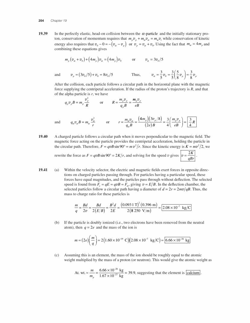
19.39 In the perfectly elastic, head-on collision between the 8-particle and the initially stationary pro-ton, conservation of momentum requires that m m mp pv v v+ =8 8 8 0 while conservation of kinetic energy also requires that v v v v v v0 00! = ! !( ) = +8 8p p or . Using the fact that m mp8 = 4 and combining these equations gives
m m mp p pv v v v8 8+( ) + ( ) = ( )0 04 4 or v v8 = 3 50
and v v v vp = ( ) + =3 5 8 50 0 0 Thus, v v v v8 = = /01
234 =3
535
58
380 p p
After the collision, each particle follows a circular path in the horizontal plane with the magnetic force supplying the centripetal acceleration. If the radius of the proton’s trajectory is R, and that of the alpha particle is r, we have
q B m
RR
m
q Bp p pp p p
p
vv v
= = =2
or mm
eBp pv
and q B mr
rmq B8 8 8
8 8 8
8v
v v= = =2
or 44 3 8
234
34
m
e B
m
eBR
p p p p( )( )( ) = /
01234
=v v
19.40 A charged particle follows a circular path when it moves perpendicular to the magnetic fi eld. The magnetic force acting on the particle provides the centripetal acceleration, holding the particle in the circular path. Therefore, F q B m r= =v vsin 90 2° . Since the kinetic energy is K m= v2 2, we
rewrite the force as F q B K r= =v sin 90 2° , and solving for the speed v gives v = 2KqBr
.
19.41 (a) Within the velocity selector, the electric and magnetic fi elds exert forces in opposite direc-tions on charged particles passing through. For particles having a particular speed, these forces have equal magnitudes, and the particles pass through without defl ection. The selected speed is found from F qE q B Fe m= = =v , giving v = E B. In the defl ection chamber, the selected particles follow a circular path having a diameter of d r m qB= =2 2 v . Thus, the mass to charge ratio for these particles is
mq
Bd BdE B
B dE
= = ( ) = = ( ) ( )2 2 2
0 0931 0 3962
2 2
v. . T m
88 2502 08 10 7
V m kg C( ) = " !.
(b) If the particle is doubly ionized (i.e., two electrons have been removed from the neutral atom), then q e= 2 and the mass of the ion is
m emq
= ( )/01
234
= "( ) "! !2 2 1 60 10 2 08 1019 7. . C kg C(( ) = " !6 66 10 26. kg
(c) Assuming this is an element, the mass of the ion should be roughly equal to the atomic weight multiplied by the mass of a proton (or neutron). This would give the atomic weight as
At. wt. kg
1.67 kg9 = "
"=
!
!mmp
6 66 1010
39 926
27
.. , suggesting that the element is calcium .
56157_19_ch19_p171-218.indd 20456157_19_ch19_p171-218.indd 204 3/18/08 11:39:47 PM3/18/08 11:39:47 PM

Magnetism 205
19.42 Since the path is circular, the particle moves perpendicular to the magnetic fi eld, and the
magnetic force supplies the centripetal acceleration. Hence, mr
q Bv
v2
= , or Bmqr
= v. But
the momentum is given by p m m KE= = ( )v 2 , and the kinetic energy of this proton is
KE = !( ) !"#$
%&'
=(
10 0 101 60 10
1 60619
..
. eV J
1 eV!! (10 12 J. We then have
Bm KE
qr=
( )=
!( ) !( )( (2 2 1 67 10 1 60 10
1
27 12. .
.
kg J
660 10 5 80 107 88 10
19 1012
!( ) !( ) = !((
C m T
..
19.43 Treat the lightning bolt as a long, straight conductor. Then, the magnetic fi eld is
B
Ir
= =! )( ) !( )
((µ
**
*0
7 4
2
4 10 1 00 10
2 100
T m A A
m
.
)) = ! =(2 T T. .00 10 20 05 µ
19.44 Imagine grasping the conductor with the right hand so the fi ngers curl around the conductor in the direction of the magnetic fi eld. The thumb then points along the conductor in the direction of the current. The results are
(a) toward the left (b) out of page (c) lower left to upper right
19.45 The magnetic fi eld at distance r from a long conducting wire is B I r= µ *0 2 . Thus, if B = ! (1 0 10 15. T at r = 4 0. cm, the current must be
I
rB= =( ) !( )
! )
(
(2 2 0 040 1 0 10
100
15*µ
**
. . m T
4 T7 mm A A= ! (2 0 10 10.
19.46 Model the tornado as a long, straight, vertical conductor and imagine grasping it with the right hand so the fi ngers point northward on the western side of the tornado (that is, at the observatory’s location). The thumb is directed downward, meaning that theconventional current is downward or negativee charge flows upward .
The magnitude of the current is found from B I r= µ *0 2 as
I
rB= =!( ) !( )
!
(
(2 2 9 00 10 1 50 10
0
3 8*µ
**
. . m T
4 10 7 T m A A
)= 675
19.47 From B I r= µ *0 2 , the required distance is
rIB
= =! )( )( )
!( )(
(
µ*
**
032
20
2 1 7 10
4 10 T m A A
T
7
.== ! =(2 4 10 2 43. . m mm
56157_19_ch19_p171-218.indd 20556157_19_ch19_p171-218.indd 205 3/19/08 3:38:35 AM3/19/08 3:38:35 AM
206 Chapter 19
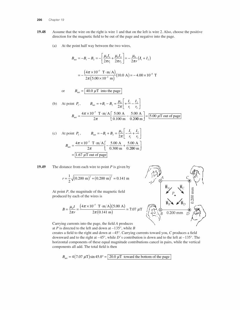
19.48 Assume that the wire on the right is wire 1 and that on the left is wire 2. Also, choose the positive direction for the magnetic fi eld to be out of the page and negative into the page.
(a) At the point half way between the two wires,
B B BIr
Ir rnet = ! ! = ! +
)*6
+,7 = !1 2
0 1
1
0 2
2
0
2 2 2µ#
µ#
µ#
II I1 2
74 1010 0
+( )
= !" -( )
"( )!
!
##
T m A
2 5.00 10 m2. A T( ) = ! " !4 00 10 5.
or Bnet T into the page= 40 0. µ
(b) At point P1 , B B BIr
Irnet = + ! = + !
)*6
+,71 2
0 1
1
2
22µ#
Bnet
T m A2
A0.100 m
A0.20
= " - !!4 10 5 00 5 007##
. .00 m
T out of page)*6
+,7
= 5 00. µ
(c) At point P2 , B B BIr
Irnet = ! + = ! +
)*6
+,71 2
0 1
1
2
22µ#
Bnet
T m A2
A0.300 m
A0.2
= " - ! +!4 10 5 00 5 007##
. .000 m
T out of page
)*6
+,7
= 1 67. µ
19.49 The distance from each wire to point P is given by
r = ( ) + ( ) =1
20 200 0 200 0 1412 2. . . m m m
At point P, the magnitude of the magnetic fi eld produced by each of the wires is
B
Ir
= =" -( )( )
( ) =!µ
##
#0
7
2
4 10 5 00
2 0 141
T m A A
m
.
.77 07. Tµ
Carrying currents into the page, the fi eld A produces at P is directed to the left and down at – 1 35°, while B creates a fi eld to the right and down at – 45°. Carrying currents toward you, C produces a fi eld downward and to the right at – 45°, while D’s contribution is down and to the left at – 135°. The horizontal components of these equal magnitude contributions cancel in pairs, while the vertical components all add. The total fi eld is then
Bnet T T toward the= ( ) =4 7 07 45 0 20 0. sin . .µ µ° bottom of the page
56157_19_ch19_p171-218.indd 20656157_19_ch19_p171-218.indd 206 3/18/08 11:39:48 PM3/18/08 11:39:48 PM

Magnetism 207
19.50 Call the wire carrying a current of 3.00 A wire 1 and the other wire 2. Also, choose the line run-ning from wire 1 to wire 2 as the positive x-direction.
(a) At the point midway between the wires, the fi eld due to each wire is parallel to the y-axis and the net fi eld is
B B B I I ry ynet = + ! = !( )1 2 0 1 2 2µ #
Thus, Bnet
T m A
m A A=
" -( )( ) !
!4 10
2 0 1003 00 5 00
7## .
. .(( ) = ! " !4 00 10 6. T
or Bnet T toward the bottom of the page= 4 00. µ
(b) At point P, r1 0 200 2= ( ). m and B1 is directed at &1 135= + °.
The magnitude of B1 is
BIr1
0 1
1
7
2
4 10 3 00
2 0 200 2= =
" -( )( )!µ#
##
T m A A
.
. mm T( ) = 2 12. µ
The contribution from wire 2 is in the –x-direction and has magnitude
B
Ir2
0 2
2
7
2
4 10 5 00
2 0 200= =
" -( )( )!µ#
##
T m A A
m
.
.(( ) = 5 00. Tµ
Therefore, the components of the net fi eld at point P are:
B B Bx = +
= ( ) +
1 2135 180
2 12 135 5
cos cos
. cos
° °
° T .0µ 00 T Tµ µ( ) = !cos .180 6 50°
and B B By = + = ( ) + = +1 2135 180 2 12 135 0sin sin . sin° ° ° Tµ 11 50. Tµ
Therefore, B B Bx ynet T= + =2 2 6 67. µ at
& µµ
=/
012
34=
/01
234
! !tan tan..
1 1 6 501 50
B
Bx
y
T T
== 77 0. °
or Bur
net T at 77.0° to the left of vert= 6 67. µ iical
19.51 Call the wire along the x-axis wire 1 and the other wire 2. Also, choose the positive direction for the magnetic fi elds at point P to be out of the page.
At point P, B B BIr
Ir
Ir
Irnet = + ! = ! = !1 2
0 1
1
0 2
2
0 1
1
2
22 2 2µ#
µ#
µ#
//01
234
or Bnet
T m A A m
A=" -( )
!!4 10
27 003 00
6 004 0
7##
.
... 00
1 67 10 7
m T/
01234 = + " !.
Bnet T out of the page= 0 167. µ
56157_19_ch19_p171-218.indd 20756157_19_ch19_p171-218.indd 207 3/18/08 11:39:49 PM3/18/08 11:39:49 PM

208 Chapter 19
19.52 (a) Imagine the horizontal x y plane being perpendicular to the page, with the positive x-axis coming out of the page toward you and the positive y-axis toward the right edge of the page. Then, the vertically upward positive z-axis is directed toward the top of the page. With the current in the wire fl owing in the positive x-direction, the right-hand rule 2 gives the direction of the magnetic fi eld above the wire as being toward the left, or in the -direction.!y
(b) With the positively charged proton moving in the !x-direction (into the page), right-hand rule 1 gives the direction of the magnetic force on the proton as being directed toward the top of the page, or upward, in the positive -directionz .
(c) Since the proton moves with constant velocity, a zero net force acts on it. Thus, the magnitude of the magnetic force must equal tthat of the gravitational force .
(d) :F ma F Fz z m g= = ; =0 or q B mgv = where B I d= µ #0 2 . This gives
q I
dmg
vµ#
0
2= , or the distance the proton is above the wire must be d
q Img
= vµ#
0
2.
(e) dq I
mg= =
"( ) "( ) "!vµ#
#0
19 4
2
1 60 10 2 30 10 4 1. . C m s 00 1 20 10
2 1 67 10 9
7 6
27
! !
!
-( ) "( )"( )
T m A A
kg
.
. .# 880 m s2( )
d = " =!5 40 10 5 402. . m cm
19.53 (a) From B I r= µ #0 2 , observe that the fi eld is inversely proportional to the distance from the conductor. Thus, the fi eld will have one-tenth its original value if the distance is increased by a factor of 10. The required distance is then < = = ( ) =r r10 10 0 400 4 00. . .m m
(b) A point in the plane of the conductors and 40.0 cm from the center of the cord is located 39.85 cm from the nearer wire and 40.15 cm from the far wire. Since the currents are in opposite directions, so are their contributions to the net fi eld. Therefore, B B Bnet = !1 2, or
BI
r rnet
T m A = !
/01
234
=" -( )!µ
##
0
1 2
7
21 1 4 10 2 00. AA
21
0.398 5 m1
0.401 5 m
T
( )!
/01
234
= " !
#
7 50 10 9. == 7 50. nT
(c) Call r the distance from cord center to fi eld point P and 2 3 00d = . mm the distance between centers of the conductors.
B
Ir d r d
I dr dnet =
!!
+/01
234 =
!/01
23
µ#
µ#
0 02 22
1 12
244
7 50 10
4 10 2 00
23 00 110
7
.. ." =
" -( )( ) "!!
T T m A A#
#00
2 25 10
3
2 6
!
!! "/01
234
m m2r .
so r = 1 26. m
The fi eld of the two-conductor cord is weak to start with and falls off rapidly with distance.
(d) The cable creates zero fi eld at exterior points, since a loop in Ampère’s law encloses zero total current.
56157_19_ch19_p171-218.indd 20856157_19_ch19_p171-218.indd 208 3/18/08 11:39:50 PM3/18/08 11:39:50 PM

Magnetism 209
19.54 (a) Point P is equidistant from the two wires, which carry identical currents. Thus, the contributions of the two wires, B
urupper and B
urlower, to the magnetic fi eld at P will
have equal magnitudes. The horizontal components of these contributions will cancel, while the vertical components add. The resultant fi eld will be vertical, in the -direction+ y .
(b) The distance of each wire from point P is r x d= +2 2 , and the cosine of the angle that B
urupper
and Bur
lower make with the vertical is cos! = x r . The magnitude of either B
urupper or B
urlower is B I rwire = µ "0 2 and the vertical components of either
of these contributions have values of
B BIr
xr
Ixrywire wire( ) = ( ) = #
$%&'( =cos! µ
"µ"
0 0
2 2 22
The magnitude of the resultant fi eld at point P is then
B BIxr
I xx dP y
= ( ) = =+( )2 0
202 2wire
µ"
µ"
(c) The point midway between the two wires is the origin (0,0). From the above result for part (b), the resultant fi eld at this midpoint is BP x= =
00 . This is as expected, because right-
hand rule 2 shows that at the midpoint the fi eld due to the upper wire is toward the right, while that due to the lower wire is toward the left. Thus, the two fi elds cancel, yielding a zero resultant fi eld.
19.55 The force per unit length that one wire exerts on the other is F I I dl = µ "0 1 2 2 , where d is the distance separating the two wires. In this case, the value of this force is
Fl
=) *( )( )
)( ) =+
+
4 10 3 0
2 6 00 103
7 2
2
""
T m A A
m
.
..00 10 5) + N m
Imagine these two wires lying side by side on a table with the two currents fl owing toward you, wire 1 on the left and wire 2 on the right. Right-hand rule 2 shows the magnetic fi eld due to wire 1 at the location of wire 2 is directed vertically upward. Then, right-hand rule 1 gives the direc-tion of the force experienced by wire 2, with its current fl owing through this fi eld, as being to the left, back toward wire 1. Thus, the force one wire exerts on the other is an attractive force.
19.56 (a) The force per unit length that parallel conductors exert on each other is F I I dl = µ "0 1 2 2 . Thus, if F l = ) +2 0 10 4. N m, I1 5 0= . A, and d = 4 0. cm, the current in the second wire must be
IdI
F2
0 1
2
7
2 2 4 0 10
4 10= #
$%&'( =
)( )) *
+
+
"µ
""l
. m
T mm A A N m A( )( ) )( ) =+
5 02 0 10 8 04
.. .
(b) Since parallel conductors carrying currents in the same direction attract each other (see Section 19.8 in the textbook), the currents in these conductors which repel each other must be in opposite directions .
continued on next page
56157_19_ch19_p171-218.indd 20956157_19_ch19_p171-218.indd 209 3/19/08 3:38:35 AM3/19/08 3:38:35 AM

210 Chapter 19
(c) The result of reversing the direction of either of the currents would be that the force of interaction would change from a forrce of repulsion to an attractive force . The
expression for the force per unit length, F I I dl = µ !0 1 2 2 , shows that doubling either
of the currents would double the magnitude of the force of interacction .
19.57 In order for the system to be in equilibrium, the repulsive magnetic force per unit length on the top wire must equal the weight per unit length of this wire.
Thus, FL
I Id
= =µ!
0 1 2
20 080. N m, and the distance between the wires will be
dI I= ( ) =
" #( )( )$µ!
!0 1 2
7
2 0 080
4 10 60 0
.
.
N m
T m A A 330 0
2 0 080
4 5 10 4 53
.
.
. .
A
N m
m mm
( )( )
= " =$
!
19.58 The magnetic forces exerted on the top and bottom segments of the rectangular loop are equal in magnitude and opposite in direction. Thus, these forces cancel, and we only need consider the sum of the forces exerted on the right and left sides of the loop. Choosing to the left (toward the long, straight wire) as the positive direction, the sum of these two forces is
F
I Ic
I Ic a
I Icnet = + $
+( ) =µ!
µ!
µ!
0 1 2 0 1 2 0 1 2
2 2 21l l l $$
+%&'
()*
1c a
or Fnet
T m A A A m=
" #( )( )( )($4 10 5 00 10 0 0 4507! . . . ))$%
&'()*
= + " =$
21
0 1001
0 250
2 70 10 25
! . .
. .
m m
N 770 10 5" $ N to the left
19.59 The magnetic fi eld inside of a solenoid is B nI N L I= = ( )µ µ0 0 . Thus, the current in this solenoid must be
IBL
N= =
"( ) "( )" #
$ $
$µ !0
3 2
7
2 0 10 6 0 10
4 10
. . T m
T m AA A( )( ) =
303 2.
19.60 The magnetic fi eld inside of a solenoid is B nI N L I= = ( )µ µ0 0 . Thus, the number of turns on this solenoid must be
NBL
I= = ( )( )
" #( )( )$µ !07
9 0 0 50
4 10 75
. . T m
T m A A== "4 8 104. turns
56157_19_ch19_p171-218.indd 21056157_19_ch19_p171-218.indd 210 3/19/08 3:38:36 AM3/19/08 3:38:36 AM

Magnetism 211
19.61 (a) From R L A= = , the required length of wire to be used is
LR A= - =
( ) "( ))*
+,
"
!
!=
#5 00 0 500 10 4
1 7 10
3 2. .
.
m>88 58 m
m> -
=
The total number of turns on the solenoid (that is, the number of times this length of wire will go around a 1.00 cm radius cylinder) is
NL
r= =
"( ) = " =!258
2 1 00 109 2 10 920
22
# # m
m..
(b) From B nI= µ0 , the number of turns per unit length on the solenoid is
nB
I= = "
" -( )( ) =!
!µ #0
24 00 104 00
7.
..
T4 10 T m A A7
996 103" turns m
Thus, the required length of the solenoid is
LNn
= = ""
= =9 2 107 96 10
0 12 122
3
..
. turns
turns m m cm
19.62 The magnetic fi eld inside the solenoid is
B nI= = " -( ) /
01234
!µ #0 174 10 30
100 T m A
turnscm
cmm1 m
A T/01
234
)*6
+,7( ) = " !15 0 5 65 10 2. .
Therefore, the magnitude of the magnetic force on any one of the sides of the square loop is
F BI L= ° = "( )( ) "!
2290 0 5 65 10 0 200 2 00 1sin . . . . T A 00 2 26 102 4! !( ) = " m N.
The forces acting on the sides of the loop lie in the plane of the loop, are perpendicular to the sides, and are directed away from the interior of the loop. Thus, they tend to stretch the loop but do not tend to rotate it. The torque acting on the loop is ( = 0 .
19.63 (a) The magnetic force supplies the centripetal acceleration, so q B m rv v= 2 . The magnetic fi eld inside the solenoid is then found to be
Bmq r
= ="( ) "( )"
!
!
v 9 11 10 1 0 10
1 60 10
31 4
1
. .
.
kg m s99 2
6
2 0 102 8 10 2 8
C m T T( ) "( ) = " =!
!
.. . µ
(b) From B nI= µ0 , the current is the solenoid is found to be
IB
n= = "
" -( ) ( )!
!µ #0
62 8 1025
. T4 10 T m A turns cm7 1100 1
8 9 10 4
cm m
A 0.89 mA
( ))* +,
= " =!.
56157_19_ch19_p171-218.indd 21156157_19_ch19_p171-218.indd 211 3/18/08 11:39:52 PM3/18/08 11:39:52 PM

212 Chapter 19
19.64 (a) When switch S is closed, a total current NI (current I in a total of N conductors) fl ows toward the right through the lower side of the coil. This results in a downward force of magnitude F B NI wm = ( ) being exerted on the coil by the magnetic fi eld, with the requirement that the balance exert a upward force
! =F mg on the coil to bring the system back into balance.
In order for the magnetic force to be downward, the right-hand rule number 1 shows that the magnetic fi eld must be directed out of the page toward the reader. For the system to be restored to balance, it is necessary that
F F B NI w mgm = ! ( ) = or , giving BmgNIw
=
(b) The magnetic fi eld exerts forces of equal magnitudes and opposite directions on the two sides of the coil. These forces cancel each other and do not afffect the balance of the coil. Hence the dimension of the sizes is not needed.
(c) BmgNIw
= ="( )( )
( )(#20 0 10 9 80
50 0 30
3. .
.
kg m s
A
2
)) "( ) =#5 0 100 26
2..
m T
19.65 (a) The magnetic fi eld at the center of a circular current loop of radius R and carrying current I is B I R= µ0 2 . The direction of the fi eld at this center is given by right-hand rule number 2. Taking out of the page (toward the reader) as positive the net magnetic fi eld at the common center of these coplanar loops is
B B BIr
Irnet
T m A= # = # =
" $( )#
2 10 2
2
0 1
1
7
2 2
4 10
23µ µ % .. .
.
010
5 010
5 2 1
A9.0 m
A12 m2 2"
#"
&'(
)*+
= # "
# #
00 5 26# = T T into the page. µ
(b) To have Bnet = 0, it is necessary that I r I r2 2 1 1= , or
rII
r22
11
3 012 7 2=
&'(
)*+
= &'(
)*+ ( ) =.
. A
5.0 A cm cm
19.66 Since the magnetic force must supply the centripetal acceleration, q B m rv v= 2 or the radius of the path is r m qB= v .
(a) The time for the electron to travel the semicircular path (of length %r ) is
tr m
qBm
qB= = &
'()*+
= ="( )#% % % %
v vv 9 11 10 31. kg
1.600 10 C T
s 1 ns
19"( )( )
= " =
#
#
0 010 0
1 79 10 799
.
. .
continued on next page
56157_19_ch19_p171-218.indd 21256157_19_ch19_p171-218.indd 212 3/19/08 3:38:37 AM3/19/08 3:38:37 AM

Magnetism 213
(b) The radius of the semicircular path is 2.00 cm. From r m qB= v , the momentum of the electron is p = mv = qBr, and the kinetic energy is
KE mm
mq B r
m= = ( ) = =
"( )!12
22 2 2 2 19 2
2 2
1 60 10 0v
v . . C 0010 0 2 00 10
2 9 11
2 2 2 T m
10 kg31
( ) "( )"( )
!
!
.
.
KE = "( ) "/01
234 =!
!5 62 101
316. . J keV
1.60 10 J16 551 keV
19.67 Assume wire 1 is along the x-axis and wire 2 along the y-axis.
(a) Choosing out of the page as the positive fi eld direction, the fi eld at point P is
B B BIr
Ir
= ! = !/01
234
=" -( )!
1 20 1
1
2
2
7
2
4 10
2µ#
# T m A
##5 00 3 00
5 00 10
. .
.
A0.400 m
A0.300 m
!/01
234
= " !! =7 0 500 T T out of the page. µ
(b) At 30.0 cm above the intersection of the wires, the fi eld components are as shown at the right, where
B BIry = ! = !
= !" -( )( )!
10 1
7
2
4 10 5 00
2 0
µ#
##
T m A A.
.33003 33 10 6
m T( ) = ! " !.
and B BIrx = = =
" -( )( )!
20 2
7
2
4 10 3 00
2 0 300µ#
##
T m A A.
. m T( ) = " !2 00 10 6.
The resultant fi eld is
B B Bx y= + = " !2 2 63 89 10. T
at
& =
/01
234
= ! °!tan 1 B
By
x
59 0.
or rB = °3 89. T at 59.0 clockwise from + direµ x cction
56157_19_ch19_p171-218.indd 21356157_19_ch19_p171-218.indd 213 3/18/08 11:39:54 PM3/18/08 11:39:54 PM

214 Chapter 19
19.68 For the rail to move at constant velocity, the net force acting on it must be zero. Thus, the magni-tude of the magnetic force must equal that of the friction force giving BIL mgk= ( )µ , or
B
mgIL
k= ( ) =( )( )( )µ 0 100 0 200 9 80
10 0
. . .
.
kg m s
2
AA m T( )( ) = " !
0 5003 92 10 2
..
19.69 (a) Since the magnetic fi eld is directed from N to S (that is, from left to right within the artery), positive ions with velocity in the direction of the blood fl ow experience a magnetic defl ec-tion toward electrode A. Negative ions will experience a force defl ecting them toward electrode B. This separation of charges creates an electric fi eld directed from A toward B. At equilibrium, the electric force caused by this fi eld must balance the magnetic force, so
q B qE q V dv = = ( )5
or v = = "( ) "( ) =
!
!
5VBd
160 103 00
16 V
0.040 0 T 10 m3..333 m s
(b) The magnetic fi eld is directed from N to S. If the charge carriers are negative moving in the direction of
rv, the magnetic force is directed toward point B. Negative charges build up at
point B, making the potential at A higher than that at B. If the charge carriers are positive moving in the direction of
rv, the magnetic force is directed toward A, so positive charges
build up at A. This also makes the potential at A higher than that at B. Therefore, the sign of the potential difference does not depend on the charge of the ions .
19.70 (a) The magnetic force acting on the wire is directed upward and of magnitude
F BIL BILm = =sin 90°
Thus, aF
mF mg
mBI
m Lgy
y m= = ! = ( ) !:
, or
ay =
"( )( )"
!!
!
4 0 10 2 0
5 0 109 80
3
4
. .
..
T A
kg m m s2 == 6 2. m s2
(b) Using 5y t a ty y= +v021
2 with v0 0y = gives
ty
ay
= ( ) = ( ) =2 2 0 506 2
0 405 .
..
m m s
s2
56157_19_ch19_p171-218.indd 21456157_19_ch19_p171-218.indd 214 3/18/08 11:39:54 PM3/18/08 11:39:54 PM

Magnetism 215
19.71 Label the wires 1, 2, and 3 as shown in Figure 1, and let B B B1 2 3, , and respectively represent the magnitudes of the fi elds produced by the currents in those wires. Also, observe that & = 45° in Figure 1.
At point A, B B I a1 2 0 2 2= = ( )µ # or
B B1 2
74 10 2 0
2 0 010 228= =
" -( )( )( ) =!#
# T m A A
m
.
.µµT
and BIa3
0
7
2 3
4 10 2 0
2 0 030= ( ) =
" -( )( )!µ#
##
T m A A
m
.
.(( ) = 13 Tµ
These fi eld contributions are oriented as shown in Figure 2. Observe that the horizontal components of
r rB B1 2 and cancel
while their vertical components add to rB3. The resultant
fi eld at point A is then
B B B BA = +( ) + =1 2 345 53cos ° Tµ , or
rBA = 5 T directed toward the bottom of the3 µ page
At point B, B BIa1 2
0
7
2
4 10 2 0
2 0 010= = =
" -( )( )!µ#
##
T m A A
m
.
.(( ) = 40 Tµ
and BIa3
0
2 220= ( ) =µ
#µ T . These contributions are oriented as
shown in Figure 3. Thus, the resultant fi eld at B is
r rB BB = =3 20 T directed toward the bottom ofµ the page
At point C, B B I a1 2 0 2 2 28= = ( ) =µ # µ T while
B I a3 0 2 40= =µ # µ T . These contributions are oriented as shown in Figure 4. Observe that the horizontal components of
r rB B1 2 and cancel while their vertical
components add to oppose rB3. The magnitude of the
resultant fi eld at C is
B B B BC = +( ) !
= ( ) ! =
1 2 345
56 45 40 0
sin
sin
°
° T Tµ µ
Figure 1
Figure 2
Figure 3
Figure 4
56157_19_ch19_p171-218.indd 21556157_19_ch19_p171-218.indd 215 3/18/08 11:39:55 PM3/18/08 11:39:55 PM

216 Chapter 19
19.72 (a) Since one wire repels the other, the currents must be in opposite directions .
(b) Consider a free body diagram of one of the wires as shown at the right.
!F T mgy = " =0 8 0 cos . °
or Tmg=
cos .8 0°
!F F Tmg
x m= " = = #$%
&'( °0 8 0
8 08 0 sin .
cos .sin .°
°
or F mgm = ( ) tan .8 0°. Thus, µ
)0
2
28 0
I Ld
mg= ( ) °tan . which gives
I
d m L g=
( )*+ ,- tan .8 0
20
°
µ )
Observe that the distance between the two wires is
d = ( )*+ ,- =2 6 0 8 0 1 7. sin . . cm cm° , so
I =
.( )( )( ) °/1 7 10 0 040 9 80 8 0
2
2. . . tan . m kg m m s2
..0 1087. 0
=/ T m A6 A
19.73 Note: We solve part (b) before part (a) for this problem.
(b) Since the magnetic force supplies the centripetal acceleration for this particle, q B m rv v= 2
or the radius of the path is r m qB= v . The speed of the particle may be written as
v = ( )2 KE m , so the radius becomes
rm KE
qB=
( )=
.( ) .( )/2 2 1 67 10 5 00 10 1 627 6. . . kg eV 00 10
10 0 050 0
6 46
19.( ).( )( )
=
/
/
J eV
1.60 C T19 .
. m
Consider the circular path shown at the right and observe that the desired angle is
1 = #$
&' = #
$&' =/ /sin
.sin
..1 11 00 1 00
8m m
6.46 mr990°
continued on next page
56157_19_ch19_p171-218.indd 21656157_19_ch19_p171-218.indd 216 3/19/08 3:38:37 AM3/19/08 3:38:37 AM

Magnetism 217
(a) The constant speed of the particle is v = ( )2 KE m, so the vertical component of the momentum as the particle leaves the fi eld is
p m m m KE m m KEy y= = ! = ! ( )( ) = ! ( )v v sin sin sin8 8 82 2
or
py = ! ( ) "( ) "( )!sin . . .8 90 2 1 67 10 5 00 1027 6° kg eV 11 60 10
8 00 10
19
21
.
.
"( )
= ! " -
!
!
J eV
kg m s
19.74 The force constant of the spring system is found from the elongation produced by the weight acting alone.
k
Fx
mgx
= = ="( )( )
"
!
!
10 0 10 9 80
0 50 10
3
2
. .
.
kg m s
2
mm N m= 19 6.
The total force stretching the springs when the fi eld is turned on is
:F F mg kxy m= + = total
Thus, the downward magnetic force acting on the wire is
F kx mgm = !
= ( ) "( ) ! "!
total
N m m19 6 0 80 10 10 0 12. . . 00 9 80
5 9 10
3
2
!
!
( )( )
= "
kg m s
N
2.
.
Since the magnetic force is given by F BILm = sin 90°, the magnetic fi eld is
BFIL
FV R L
m m= = ( ) =( ) "( )( )
!
5>12 5 9 10
24 5 0
2 N
V
.
. ""( ) =!100 59
2 m T.
19.75 The magnetic force is very small in comparison to the weight of the ball, so we treat the motion as that of a freely falling body. Then, as the ball approaches the ground, it has velocity compo-nents with magnitudes of
v vx x= =0 20 0. m s, and
v vy y ya y= + ( ) = + !( ) !( ) =0
2 2 0 2 9 80 20 0 195 . . . m s m2 88 m s
The velocity of the ball is perpendicular to the magnetic fi eld and, just before it reaches the
ground, has magnitude v v v= + =x y2 2 28 1. m s. Thus, the magnitude of the magnetic force is
F q Bm =
= "( )( )( )!
v sin
. . .
&
5 00 28 1 0 010 010 C m s T6 ssin . .90 0 1 41 10 6° = " ! N
56157_19_ch19_p171-218.indd 21756157_19_ch19_p171-218.indd 217 3/18/08 11:39:56 PM3/18/08 11:39:56 PM

218 Chapter 19
19.76 (a) BId1
0 1
7
2
4 10 5 00
2 0 100= =
" -( )( )(
!µ#
##
T m A A
m
.
. )) = " !1 00 10 5. T
(b) F
B I211 2
5 51 00 10 8 00 8 00 10l
= = "( )( ) = "! !. . . T A N directed toward wire 1
(c) BId2
0 2
7
2
4 10 8 00
2 0 100= =
" -( )( )(
!µ#
##
T m A A
m
.
. )) = " !1 60 10 5. T
(d) F
B I122 1
5 51 60 10 5 00 8 00 10l
= = "( )( ) = "! !. . . T A N directed toward wire 2
56157_19_ch19_p171-218.indd 21856157_19_ch19_p171-218.indd 218 3/18/08 11:39:57 PM3/18/08 11:39:57 PM


![Subroutines and ControlAbstraction - Elsevier · 2013-06-03 · CD_Ch08-P374514 [11:51 2009/2/25] SCOTT: Programming Language Pragmatics Page: 192 379–215 192 Chapter 8 Subroutines](https://img.pdfslide.us/doc/110x75/5e75eb163016225d5a57c47b/subroutines-and-controlabstraction-elsevier-2013-06-03-cdch08-p374514-1151.jpg)