Embed Size (px)
Citation preview
(19) United States US 20110148349A1
(12) Patent Application Publication (10) Pub. No.: US 2011/0148349 A1 KM et al. (43) Pub. Date: Jun. 23, 2011
(54) APPARATUS AND METHOD FORCHARGING INTERNAL BATTERY IN WIRELESS SENSOR NETWORK
(75) Inventors: Se Han KIM, Daejeon (KR): Nae Soo Kim, Daejeon (KR); Ho Yong Kang, Daejeon (KR); Kyo Hoon Son, Daejeon (KR); Cheol Sig Pyo, Daejeon (KR)
(73) Assignee: Electronics and Telecommunications Research Institute of Daejeon
(21) Appl. No.: 12/885,872
(22) Filed: Sep. 20, 2010
(30) Foreign Application Priority Data
Dec. 17, 2009 (KR) ........................ 10-2009-O125926
Power On
received
Sassociation request message received
Yes
Generate energy table and perform E. phase 818
Transmit beacon message and power
Sbeacon request message
Publication Classification
(51) Int. Cl. H02. 7/00 (2006.01)
(52) U.S. Cl. ........................................................ 32O/108 (57) ABSTRACT
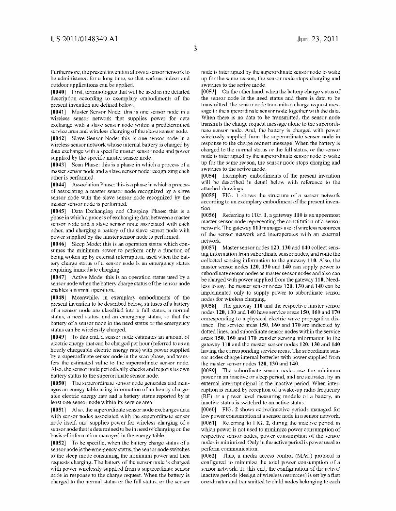
Provided are an apparatus and method for charging an inter nal battery in a wireless sensor network. A method for a slave sensor node to charge an internal battery in a sensor network includes estimating an hourly chargeable electric energy rate in a scan phase with a master sensor node, transmitting the estimated hourly chargeable electric energy rate using an association request message requesting association with the master sensor node after recognizing the master sensor node, requesting charging from the master sensor node and per forming wireless charging when a power level of an internal battery requires charging, reporting the power level of the internal battery varied by the wireless charging to the master sensor node by predetermined time periods during the wire less charging, and stopping the wireless charging when the power level reported to the master sensor node reaches a predetermined power level.
Emergency/Need What
Exchange data
Update energy table with reported power level
charge request message received
O
status does reported power eyel correspond to
Normal/Full 830
No is power level changed? 8 es 32
Transmit Wake-up message
Stop wireless charging 834
822
24 Yes 8
828
Perform wireless charging

Patent Application Publication Jun. 23, 2011 Sheet 1 of 8 US 2011/O148349 A1
N
- 1 Y. 1 Y
/ \- 170 150 / - V - - -
110 / N & -A - - -1 w - 1 ~, s / \ \
- 1 N N / S v Gateway - (S) - \ w f G5-31 f 140 M AC 120 - - - - - - M | \ - N f
Y 11 N / ? \ V M 1 N A. V a // N N(S) / / N N 1 / 11 YS - -
Y S ^ 130 ?--------1 Y f 1 -- N --- - - - Y- Y-1
W ---- - - - W f V w
-N / 160 N. 1 N Y
mA Beginning time III III ,

Patent Application Publication Jun. 23, 2011 Sheet 2 of 8 US 2011/O148349 A1
FIG 3
312
Transceiver
Wake-Up RF
314 Wake-Up
Interrupt
POWer receiver (donor
Charge and COntrol circuit
FIG. 4
Battery Level Reference Wake-Up
rail attery indicator

Patent Application Publication Jun. 23, 2011 Sheet 3 of 8 US 2011/O148349 A1
FIG 5
ELFULL
EL Normal
EL Need
ELEmergency

Patent Application Publication Jun. 23, 2011 Sheet 4 of 8 US 2011/O148349 A1
FIG. 6 MASTER NODE SLAVENODE
PASSIVESCAN PHASE
ASSOCATION REQUEST MASSAGE ACKNOWLEDGEMENT MASSAGE
D AIA REQUEST MASSAGE ACKNOWLEDGEMENT MASSAGE
“RPONSE MASSAGE .
ASSOCATION RESPONSE MASSAGE ACKNOWLEDGEMENRI MASSAGE
l

Patent Application Publication Jun. 23, 2011 Sheet 5 of 8 US 2011/O148349 A1
FIG.7
POWer. On 710
beacon message 712 received?
716 Yes
Perform active scan Perform passive scan 714 and receive power and receive power
Estimate hourly chargeable 718 electric energyrate
Report hourly chargeable electric energyrate estimated-720
in association phase
Check power level of FA battery 722
hat status does 724 Normal/Full Emergency power level correspond to
728 Need 732
Transmit charge Does data to be No request message transmitted exist?
730 Yes itj34 736 726 Perform wireless Transmit data and Transmit charge Perform operation
in active mode charing in sleep mode charge request message
Perform wireless 738 charging in active mode
Report power level 740
request message

Patent Application Publication Jun. 23, 2011 Sheet 6 of 8 US 2011/O148349 A1
FIG.8 Power On 810
Transmit beacon message and power
beacon request message received
Sassociation request message received?
Yes
Generate energy table and perform E. phase 818
Exchange data
Update energy table with reported power level
8 Scharge request message
O
8 What status does reported power
eyel COrrespond to 28 Emergency/Need
Normal/Full 830
No Is power level changed? 8 CS 32
Transmit Wake-up message Perform wireless charging
Stop wireless charging 834

Patent Application Publication Jun. 23, 2011 Sheet 7 of 8 US 2011/0148349 A1
FIG.9 Energy Table Slave Node Address Energy level Status 1st Charge Reserved Charge Power/Sec
FIG.10
Frame Sequence Addressing Auxiliary Sequence GTS Pending FCS Control fields Security Specification fields address
Header (Figure 45) fields (Figure 46)
MAC Payload
Octets:(see 72.24) MHR fields Command Capability
Frame identifier Information (see Table82)

Patent Application Publication Jun. 23, 2011 Sheet 8 of 8
bits: 0
FIG, 12
Command Frame Identifier Command name
OXO1 ASSOciation request Ox02 ASSOciation response
Disassociation notification see Ox05 PAN PID COnflict notification
0x06 Orphan notification
Coordination realignment Ox09 GTS request
Ox0a-Oxf Reserved
l
Alternate PAN
Coordinator
DeviceType Power Source Receiver Reserved Security On When Capability
Idle
US 2011/O148349 A1
Allocate Address

US 2011/O 148349 A1
APPARATUS AND METHOD FOR CHARGING INTERNAL BATTERY IN WIRELESS SENSOR
NETWORK
CROSS-REFERENCE TO RELATED APPLICATION
0001. This application claims priority to and the benefit of Korean Patent Application No. 10-2009-0125926, filed Dec. 17, 2009, the disclosure of which is incorporated herein by reference in its entirety.
BACKGROUND
0002 1. Field of the Invention 0003. The present invention relates to an apparatus and method for charging an internal battery in a wireless sensor network, and more particularly to an apparatus and method for charging an internal battery over a wireless channel between wireless sensor nodes. 0004 2. Discussion of Related Art 0005. In general, wireless sensor networks used in a wide range of application fields such as event/target sensing, moni toring, and tracking. In these application fields, numerous sensor nodes are densely disposed, and thus wireless sensor networks need to be intentionally designed. In other words, the management area of each sensor node should be guaran teed by ad-hoc networking. 0006. In particular, a ubiquitous sensor network (USN) denotes a network system that organizes a wireless sensor network using sensor nodes having a sensor capable of obtaining recognition information about an object or environ mental information about Surroundings, and processes and manages information input through the various sensor nodes in real time in communication with the outside over the net work. 0007. In general, sensor nodes constituting Such a sensor network are disposed at locations where it is impossible to receive operating power from the outside. Thus, in most cases, the sensor nodes can no longer be used when their battery life ends after the sensor nodes have been in a net work, or are used in a self-charging method such as Solar cell and vibration. 0008 For these reasons, it is necessary to supply power to sensor nodes constituting a sensor network from the outside while minimizing their power consumption.
SUMMARY OF THE INVENTION
0009. The present invention is directed to an apparatus and method for charging the battery of a sensor node in a sensor network and minimizing power consumption dependent on operation of the sensor node. 0010. One aspect of the present invention provides a method for at least one slave sensor node to charge an internal battery in a sensor network including a master sensor node and the at least one slave sensor node associated with the master sensor node, the method including: estimating an hourly chargeable electric energy rate in a scan phase with the master sensor node; after recognizing the master sensor node, transmitting the estimated hourly chargeable electric energy rate using an association request message requesting associa tion with the master sensor node; when a power level of an internal battery requires charging, requesting charging from the master sensor node and performing wireless charging; during the wireless charging, reporting the power level of the
Jun. 23, 2011
internal battery varied by the wireless charging to the master sensor node by predetermined time periods; and when the power level reported to the master sensor node reaches a predetermined power level, stopping the wireless charging. 0011. The power level of the internal battery may be clas sified as a full status, a normal status, a need Status, or an emergency status, and when the power level of the internal battery corresponds to the need Status or the emergency sta tus, it may be determined that charging is needed. 0012. The predetermined power level may correspond to one of the full status and the normal status.
(0013 When the power level of the internal battery corre sponds to the need status, the wireless charging may be per formed during data communication with the master sensor node, and when the power level of the internal battery corre sponds to the emergency status, the wireless charging may be performed in a standby mode consuming a minimum power. 0014) Another aspect of the present invention provides a method for a master sensor node to charge an internal battery of at least one slave sensor node in a sensor network including the master sensor node and the at least one slave sensor node associated with the master sensor node, the method including: after recognizing at least one slave sensor node in a scan phase, receiving an association request message including an estimated hourly chargeable electric energy rate from the slave sensor node; generating an energy table on the basis of the hourly chargeable electric energy rate reported from the slave sensor node; when a charge request is received from the slave sensor node, performing wireless charging on the slave sensor node on the basis of the generated energy table; receiv ing a power level of an internal battery varied by the wireless charging from the slave sensor node on which the wireless charging is performed by predetermined time periods, and updating the energy table; and when it is determined that the power level reported from the slave sensor node on which the wireless charging is performed reaches a predetermined power level, stopping the wireless charging. 0015 The power level of the internal battery may be clas sified as a full status, a normal status, a need Status, or an emergency status, and when the power level of the internal battery corresponds to the need Status or the emergency sta tus, charging may be requested. 0016. The predetermined power level may correspond to one of the full status and the normal status.
0017 Still another aspect of the present invention provides a slave sensor node charging an internal battery in a sensor network including a master sensor node and at least one slave sensor node associated with the master sensor node, the slave sensor node including: a wireless charging receiving module for estimating an hourly chargeable electric energy rate in a scan phase with the master sensor node, and performing wireless charging by the master sensor node when a power level of the internal battery requires charging; and a trans ceiver for transmitting the estimated hourly chargeable elec tric energy rate using an association request message request ing association with the master sensor node after recognizing the master sensor node, requesting charging from the master sensor node when the power level of the internal battery requires charging, reporting the power level of the internal battery varied by the wireless charging to the master sensor node by predetermined time periods during the wireless charging, and stopping the wireless charging when the varied power level reaches a predetermined power level.

US 2011/O 148349 A1
0018. The power level of the internal battery may be clas sified as a full status, a normal status, a need status, or an emergency status, and when the power level of the internal battery corresponds to the need Status or the emergency sta tus, it may be determined that charging is needed. 0019. The predetermined power level may correspond to one of the full status and the normal status. 0020. When the power level of the internal battery corre sponds to the need status, the wireless charging may be per formed during data communication with the master sensor node, and when the power level of the internal battery corre sponds to the emergency status, the wireless charging may be performed in a standby mode consuming a minimum power. 0021. Yet another aspect of the present invention provides a master sensor node for charging an internal battery of at least one slave sensor node associated with the master sensor node in a sensor network including the master sensor node and the at least one slave sensor node, the master sensor node including: a controller for receiving an association request message including an estimated hourly chargeable electric energy rate from at least one slave sensor node after recog nizing the slave sensor node in a scan phase, generating an energy table on the basis of an hourly chargeable electric energy rate reported from the slave sensor node, receiving a power level of an internal battery varied by wireless charging from the slave sensor node on which the wireless charging is performed by predetermined time periods to update the energy table; a wireless charging transmitting module for Supplying power for wireless charging of the slave sensor node on the basis of the generated energy table in response to each of the scan phase, data transmission to the slave sensor node, and reception of a charge request from the slave sensor node; and a wake-up radio frequency (RF) unit for transmit ting an activation request message to the slave sensor node on which the wireless charging is performed when it is deter mined that the power level reported from the slave sensor node on which the wireless charging is performed reaches a predetermined power level. 0022. The power level of the internal battery may be clas sified as a full status, a normal status, a need status, or an emergency status, and when the power level of the internal battery corresponds to the need Status or the emergency sta tus, the charge request may be received. 0023 The predetermined power level may correspond to one of the full status and the normal status.
BRIEF DESCRIPTION OF THE DRAWINGS
0024. The above and other objects, features and advan tages of the present invention will become more apparent to those of ordinary skill in the art by describing in detail exem plary embodiments thereof with reference to the attached drawings, in which: 0.025 FIG. 1 shows the structure of a sensor network according to an exemplary embodiment of the present inven tion; 0026 FIG. 2 shows active/inactive periods managed for low power consumption at a sensor node in a sensor network; 0027 FIG.3 is a block diagram showing the configuration of a slave sensor node according to an exemplary embodiment of the present invention; 0028 FIG. 4 is a block diagram showing a detail configu ration of a charge and control circuit of the slave sensor node according to an exemplary embodiment of the present inven tion;
Jun. 23, 2011
0029 FIG. 5 shows power statuses of an internal battery in a slave sensor node according to an exemplary embodiment of the present invention; 0030 FIG. 6 illustrates signaling between a master sensor node and a slave sensor node according to an exemplary embodiment of the present invention; 0031 FIG. 7 illustrates a control flow for a slave sensor node to wirelessly charge an internal battery in a sensor network according to an exemplary embodiment of the present invention; 0032 FIG. 8 illustrates a control flow for a master sensor node to charge an internal battery of a slave sensor node in a sensor network according to an exemplary embodiment of the present invention; 0033 FIG. 9 shows an example of an energy table man aged by a master sensor node according to an exemplary embodiment of the present invention; and 0034 FIGS. 10 to 13 show tables in which messages trans mitted between a master sensor node and a slave sensor node for wireless charging are defined according to exemplary embodiments of the present invention.
DETAILED DESCRIPTION OF EXEMPLARY EMBODIMENTS
0035. Hereinafter, exemplary embodiments of the present invention will be described in detail. However, the present invention is not limited to the embodiments disclosed below but can be implemented in various forms. The following embodiments are described in order to enable those of ordi nary skill in the art to embody and practice the present inven tion. To clearly describe the present invention, parts not relat ing to the description are omitted from the drawings. Like numerals refer to like elements throughout the description of the drawings. 0036 Throughout this specification, when an element is referred to as being “connected' or “coupled to another element, it can be directly connected or coupled to the other element or electrically connected or coupled to the other element with yet another element interposed between them. 0037. Throughout this specification, when an element is referred to as “comprises.” “includes,” or “has a component, it does not preclude another component but may further include the other component unless the context clearly indi cates otherwise. Also, as used herein, the terms “... unit.’ “ ... device.” “... module.” etc., denote a unit of processing at least one function or operation, and may be implemented as hardware, software, or combination of hardware and soft Wa.
0038. The present invention suggests a method of admin istering a sensor network employing a wireless charging tech nique in consideration of a characteristic that a chargeable electric energy decreases as a distance for wireless charging increases. To this end, statuses of a battery of a slave sensor node are classified into four phases, so that a master sensor node can wirelessly charge the battery as occasion demands. At this time, wireless charging efficiency is maximized, and existing compatibility with Zigbee and institute of electrical and electronics engineers (IEEE) 802.15.4 is maintained as high as possible. 0039. Also, even when a new protocol suggested in the present invention is used, characteristics of a sensor network are maintained as they are. To this end, a message process for communication between a master sensor node and a slave sensor node and a charging process will be described in detail.
US 2011/O 148349 A1
Furthermore, the present invention allows a sensor network to be administered for a long time, so that various indoor and outdoor applications can be applied. 0040 First, terminologies that will be used in the detailed description according to exemplary embodiments of the present invention are defined below. 0041 Master Sensor Node: this is one sensor node in a wireless sensor network that Supplies power for data exchange with a slave sensor node within a predetermined service area and wireless charging of the slave sensor node. 0.042 Slave Sensor Node: this is one sensor node in a wireless sensor network whose internal battery is charged by data exchange with a specific master sensor node and power Supplied by the specific master sensor node. 0043 Scan Phase: this is a phase in which a process of a master sensor node and a slave sensor node recognizing each other is performed. 0044 Association Phase: this is a phase in which a process of associating a master sensor node recognized by a slave sensor node with the slave sensor node recognized by the master sensor node is performed. 0045 Data Exchanging and Charging Phase: this is a phase in which a process of exchanging data between a master sensor node and a slave sensor node associated with each other, and charging a battery of the slave sensor node with power Supplied by the master sensor node is performed. 0046 Sleep Mode: this is an operation status which con Sumes the minimum power to perform only a function of being woken up by external interruption, used when the bat tery charge status of a sensor node is an emergency status requiring immediate charging. 0047 Active Mode: this is an operation status used by a sensor node when the battery charge status of the sensor node enables a normal operation. 0048 Meanwhile, in exemplary embodiments of the present invention to be described below, statuses of a battery of a sensor node are classified into a full status, a normal status, a need Status, and an emergency status, so that the battery of a sensor node in the need status or the emergency status can be wirelessly charged. 0049. To this end, a sensor node estimates an amount of electric energy that can be charged per hour (referred to as an hourly chargeable electric energy rate) with power Supplied by a Superordinate sensor node in the scan phase, and trans fers the estimated value to the Superordinate sensor node. Also, the sensor node periodically checks and reports its own battery status to the Superordinate sensor node. 0050. The superordinate sensor node generates and man ages an energy table using information of an hourly charge able electric energy rate and a battery status reported by at least one sensor node within its service area. 0051. Also, the superordinate sensor node exchanges data with sensor nodes associated with the Superordinate sensor node itself, and Supplies power for wireless charging of a sensor node that is determined to be in need of charging on the basis of information managed in the energy table. 0052 To be specific, when the battery charge status of a sensor node is the emergency status, the sensor node Switches to the sleep mode consuming the minimum power and then requests charging. The battery of the sensor node is charged with power wirelessly Supplied from a Superordinate sensor node in response to the charge request. When the battery is charged to the normal status or the full status, or the sensor
Jun. 23, 2011
node is interrupted by the Superordinate sensor node to wake up for the same reason, the sensor node stops charging and switches to the active mode. 0053. On the other hand, when the battery charge status of the sensor node is the need status and there is data to be transmitted, the sensor node transmits a charge request mes sage to the Superordinate sensor node together with the data. When there is no data to be transmitted, the sensor node transmits the charge request message alone to the Superordi nate sensor node. And, the battery is charged with power wirelessly supplied from the Superordinate sensor node in response to the charge request message. When the battery is charged to the normal status or the full status, or the sensor node is interrupted by the Superordinate sensor node to wake up for the same reason, the sensor node stops charging and switches to the active mode. 0054 Exemplary embodiments of the present invention will be described in detail below with reference to the attached drawings. 0055 FIG. 1 shows the structure of a sensor network according to an exemplary embodiment of the present inven tion. 0056 Referring to FIG. 1, a gateway 110 is an uppermost master sensor node representing the constitution of a sensor network. The gateway 110 manages use of wireless resources of the sensor network and interoperates with an external network. 0057 Master sensor nodes 120, 130 and 140 collect sens ing information from Subordinate sensor nodes, and route the collected sensing information to the gateway 110. Also, the master sensor nodes 120, 130 and 140 can supply power to Subordinate sensor nodes as master sensor nodes and also can be charged with power supplied from the gateway 110. Need less to say, the master sensor nodes 120, 130 and 140 can be implemented only to Supply power to Subordinate sensor nodes for wireless charging. 0058. The gateway 110 and the respective master sensor nodes 120, 130 and 140 have service areas 150, 160 and 170 corresponding to a physical electric wave propagation dis tance. The service areas 150, 160 and 170 are indicated by dotted lines, and subordinate sensor nodes within the service areas 150, 160 and 170 transfer sensing information to the gateway 110 and the master sensor nodes 120, 130 and 140 having the corresponding service areas. The Subordinate sen sor nodes charge internal batteries with power Supplied from the master sensor nodes 120, 130 and 140. 0059. The subordinate sensor nodes use the minimum power in an inactive or sleep period, and are activated by an external interrupt signal in the inactive period. When inter ruption is caused by reception of a wake-up radio frequency (RF) or a power level measuring module of a battery, an inactive status is Switched to an active status. 0060 FIG. 2 shows active/inactive periods managed for low power consumption at a sensor node in a sensor network. 0061 Referring to FIG. 2, during the inactive period in which power is not used to minimize power consumption of respective sensor nodes, power consumption of the sensor nodes is minimized. Only in the active period is power used to perform communication. 0062. Thus, a media access control (MAC) protocol is configured to minimize the total power consumption of a sensor network. To this end, the configuration of the active/ inactive periods (design of wireless resources) is set by a first coordinator and transmitted to child nodes belonging to each
US 2011/O 148349 A1
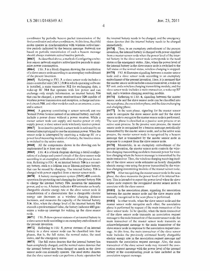
coordinator by periodic beacon packet transmission of the first coordinator and other coordinators. At this time, the child nodes operate in Synchronization with wireless active/inac tive periods indicated by the beacon message. Network use based on periodic transmission of Such a beacon message should always maintain active/inactive periods. 0063 As described above, a method of configuring a wire less sensor network employs active/inactive periods to mini mize power consumption. 0064 FIG. 3 is a block diagram showing the constitution of a slave sensor node according to an exemplary embodiment of the present invention. 0065 Referring to FIG. 3, a slave sensor node includes a micro controller unit (MCU) 310 in which operating software is installed, a main transceiver 312 for exchanging data, a wake-up RF 314 that operates with low power and can exchange only simple information, an internal battery 316 that can be charged, a power receiver?donor 320 capable of wireless power transmission and reception, a charge and con trol circuit 318, and other modules such as an antenna, a case, and a sensor. 0.066. A gateway constituting a sensor network can use Normal Power Source instead of an internal battery, and only include a power donor without a power receiver. While a master sensor node can Supply and receive power or only Supply power, a slave sensor node wirelessly receives power. 0067. In an inactive period, a sensor node is activated by an external interrupt signal to use the minimum power. When the sensor node is interrupted by receiving a wake-up RF or a power level measuring module of a battery, the inactive status is switched to the active status. 0068 All the components shown in the drawing can be implemented in at least one chip. 0069 FIG. 4 is a block diagram showing a detail configu ration of a charge and control circuit of the slave sensor node according to an exemplary embodiment of the present inven tion. Referring to FIG. 4, an internal battery 316 is a second ary battery, such as a lithium ion or lithium polymer battery, that can be reused by charging. The internal battery 316 is charged with power Supplied from a master sensor node. 0070 A battery management system (BMS) 420 controls operation for protecting and charging the internal battery 316 to charge the internal battery 316, maintain the minimum power, and so on. A battery indicator 410 estimates an hourly chargeable electric energy rate at the slave sensor node in consideration of a characteristic that a chargeable electric energy rate decreases as a wireless charging distance increases, and measures the capacity of the internal battery 316. Also, when the charge level of the internal battery 316 exceeds a predetermined value, the battery indicator 410 gen erates a wake-up interrupt for waking up the slave sensor node. 0071 FIG.5 shows power statuses of an internal battery in a slave sensor node according to an exemplary embodiment of the present invention. 0072 Referring to FIG. 5, power statuses of an internal battery in a slave sensor node can be classified into four phases, that is, the full status, the normal status, the need status, and the emergency status. 0073. The full status denotes that the internal battery has been completely charged, and the normal status denotes that the internal battery has been charged as much as the slave sensor node can normally operate. The need status denotes that the slave sensor node can perform a basic operation but
Jun. 23, 2011
the internal battery needs to be charged, and the emergency status denotes that the internal battery needs to be charged immediately. 0074 Thus, in an exemplary embodiment of the present invention, the internal battery is charged with power Supplied from a master sensor node when the power level of the inter nal battery in the slave sensor node corresponds to the need status or the emergency status. Also, when the power level of the internal battery in the slave sensor node is switched to the full status or the normal status, wireless charging is stopped. 0075 FIG. 6 illustrates signaling between a master sensor node and a slave sensor node according to an exemplary embodiment of the present invention. Here, it is assumed that the master sensor node includes a main transceiver, awake-up RF unit, and a wireless charging transmitting module, and the slave sensor node includes a main transceiver, a wake-up RF unit, and a wireless charging receiving module. 0076 Referring to FIG. 6, signaling between the master sensor node and the slave sensor node can be classified into the scan phase, the association phase, and the data exchanging and charging phase. 0077. In the scan phase, signaling for the master sensor node to recognize the slave sensor node and for the slave sensor node to recognize the master sensor node is performed. The scan phase is classified as a passive scan process or an active scan process. In the passive scan process, the master sensor node is recognized by a beacon message periodically transmitted by the master sensor node, and in the active scan process, the master sensor node is recognized by a beacon message that is transmitted by the master sensor node in response to a request from the slave sensor node. 0078 Meanwhile, in an exemplary embodiment of the present invention, the master sensor node controls the wire less charging transmitting module to transmit powerfor wire less charging when the beacon message is transmitted by the main transceiver. Thus, the wireless charging receiving mod ule of the slave sensor node estimates an hourly chargeable electric energy rate using the power transmitted by the wire less charging transmitting module of the master sensor node. 0079. After recognizing the master sensor node in the scan phase, the slave measures the power level of its internal bat tery. This is intended to report the power level when the slave sensor node requests the recognized master sensor node to associate with the slave sensor. 0080. In the association phase, signaling for association between the master sensor node and the slave sensor node mutually recognized in the scan phase is performed. 0081. In other words, when the slave sensor node and the master sensor node recognize each other, the association phase is performed by request of the main transceiver of the slave sensor node. To be specific, when the main transceiver of the slave sensor node transmits an association request message to the main transceiver of the master sensor node, the main transceiver of the master sensor node transmits an acknowledgement message to the main transceiver of the slave sensor node in response to the association request mes sage. At this time, the main transceiver of the slave sensor node includes the previously estimated hourly chargeable electric energy rate in the association request message and transmits the association request message. Also, the main transceiver of the slave sensor node may transmit the asso ciation request message with the power level of the internal battery at the corresponding point in time included in the association request message.

US 2011/O 148349 A1
0082. When the acknowledgment message is received from the main transceiver of the master sensor node, the main transceiver of the slave sensor node transmits a data request message, and the main transceiver of the master sensor node transmits an association response message together with an acknowledgement message to the main transceiver of the slave sensor node in response to the data request message. The main transceiver of the slave sensor node receiving the association response message transmits an acknowledgement message to the main transceiver of the master sensor node in response to the association response message. 0.083 Finally, in the data exchanging and charging phase, signaling for data transmission between the main transceiver of the master sensor node and the main transceiver of the slave sensor node or wireless charging between the wireless charg ing transmitting module of the master sensor node and the wireless charging receiving module of the slave sensor node is performed. 0084. To be specific, when the master sensor node and the slave sensor node associate with each other, the main trans ceiver of the master sensor node transmits data to the main transceiver of the slave sensor node, and the main transceiver of the slave sensor node transmits an acknowledgment mes sage to the main transceiver of the master sensor node in response to the data. At this time, the wireless charging trans mitting module of the master sensor node Supplies power for wireless charging to the wireless charging receiving module of the slave sensor node. 0085. When the main transceiver of the master sensor node receives a charge request from the main transceiver of the slave sensor node, the wireless charging transmitting module of the master sensor node Supplies powerfor wireless charging to the wireless charging receiving module of the slave sensor node. I0086. When the power level of the internal battery in the slave sensor node increases as much as desired by wireless charging, the wake-up RF unit of the master sensor node transmits a wake-up message to the wake-up RF unit of the slave sensor node. The slave sensor node receiving the wake up message resumes data transmission through the main transceiver, and the main transceiver of the master sensor node transmits an acknowledgment message to the main transceiver of the slave sensor node in response to transmitted data. 0087 FIG. 7 illustrates a control flow for a slave sensor node to wirelessly charge an internal battery in a sensor network according to an exemplary embodiment of the present invention. 0088 Referring to FIG. 7, when a slave sensor node is powered on in operation 710, the slave sensor node deter mines whether a beacon message is received from a master sensor node in operation 712. The beacon message includes a wireless resource use plan, that is, the definition of active/ inactive periods and information on the master sensor node. 0089. When the beacon message is received from the mas
ter sensor node, the slave sensor node recognizes the master, sensor node through a passive scan process in operation 714. The passive scan process performed to recognize the master sensor node has already been described above, and the detailed description will not be reiterated. During the passive scan process, the slave sensor node receives power for wire less charging from the master sensor node. 0090. On the other hand, when the beacon message is not received from the master sensor node, the slave sensor node
Jun. 23, 2011
recognizes the master sensor node through an active scan process in operation 716. The active scan process performed to recognize the master sensor node has already been described above, and the detailed description will not be reiterated. During the active scan process, the slave sensor node receives power for wireless charging from the master sensor node. 0091 After recognizing the master sensor node through the active scan process or the passive scan process, the slave sensor node estimates an hourly chargeable electric energy rate in operation 718. In other words, the slave sensor node measures chargeable electric energy using the power received from the master sensor node during the passive scan process or the active scan process. At this time, the slave sensor node takes the characteristic that chargeable electric energy decreases in proportion to a distance between the nodes into consideration. Using the measured chargeable electric energy, it is possible to estimate the hourly chargeable electric energy rate. 0092. Meanwhile, when the master sensor node is recog nized as described above, the slave sensor node performs an association phase. In other words, the slave sensor node per forms a process for associating with the previously recog nized master sensor node. At this time, the slave sensor node reports the estimated hourly chargeable electric energy rate to the master sensor node in operation 720. As an example in which the slave sensor node reports the estimated hourly chargeable electric energy rate, the slave sensor node can include the estimated hourly chargeable electric energy rate in an association request message transmitted for association with the master sensor node.
0093. When the slave sensor node is associated with the master sensor node, the slave sensor node checks the power level of the internal battery in operation 722. As mentioned above, the power level of an internal battery can be classified as the full status, the normal status, the need status, or the emergency status. In an exemplary embodiment of the present invention, it is assumed that the full status and the normal status correspond to a power level that does not require charg ing, and the need status and the emergency status correspond to a power level that requires charging. 0094. When checking the power level of the internal bat tery is finished, the slave sensor node determines a status corresponding to the power level in operation 724. In other words, the slave sensor node determines an operation to per form according to the checked power level. Referring to FIG. 7, the slave sensor node performs operation 728 when it is determined that the power level of the internal battery corre sponds to the emergency status, and operation 732 when it is determined that the power level of the internal battery corre sponds to the need status. 0095. On the other hand, when it is determined that the power level corresponds to the full status or the normal status, the slave sensor node performs operation 726. In operation 726, the slave sensor node determines that the internal battery does not need to be charged, and performs general operation in the active mode. The slave sensor node reports the previ ously checked power level of the internal battery to the master sensor node. 0096. In operation 728, the slave sensor node transmits a charge request message for requesting wireless charging from the master sensor node to the master sensor node. In operation 730, the slave sensor node performs operation in the sleep mode to consume the minimum power because the current

US 2011/O 148349 A1
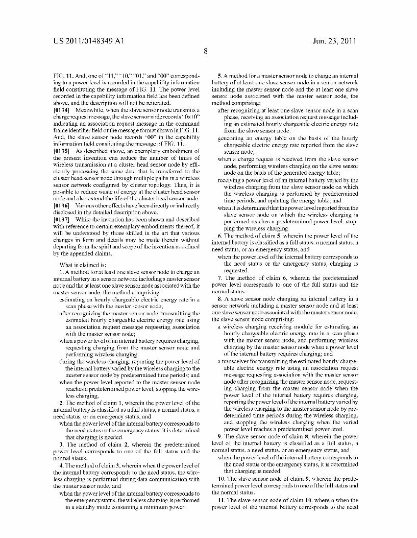
power level of the internal battery is not sufficient to perform a normal function. For example, the sleep mode denotes a status in which operation consuming only as much power as required to Switch to the active mode in response to an exter nal interrupt signal is performed. 0097. The slave sensor node charges the internal battery with power Supplied from the master sensor node in the sleep mode. In other words, the slave sensor node performs wire less charging by the master sensor node. Also, the slave sensor node reports the previously checked power level of the inter nal battery to the master sensor node in operation 740. How ever, the power level of the internal battery may be reported by the slave sensor node to the master sensor node before the charge request message is transmitted. 0098. Meanwhile, in operation 732, the slave sensor node determines whether there is data to be transmitted to the master sensor node. The slave sensor node performs opera tion 734 when there is data to be transmitted, and operation 736 when there is no data to be transmitted. 0099. In operation 734, the slave sensor node transmits a charge request message together with the data to be transmit ted to the master sensor node. At this time, the data and the charge request message may be transmitted to the master sensor node by one message or different messages. On the other hand, in operation 736, the slave sensor node transmits the charge request message to the master sensor node. 0100. After transmitting the charge request message to the master sensor node, the slave sensor node charges the internal battery with power supplied from the master sensor node in the active mode in operation 738. In other words, the slave sensor node performs wireless charging by the master sensor node. Also, the slave sensor node reports the previously checked power level of the internal battery to the master sensor node in operation 740. However, the power level of the internal battery may be reported by the slave sensor node to the master sensor node before the charge request message is transmitted. 0101. As described above, the slave sensor node charges the internal battery with power supplied from the master sensor node only when the power level of the internal battery corresponds to the need status or the emergency status, and performs general operation in the active mode without charg ing the internal battery in the full status or the normal status. 0102 Meanwhile, although not shown in FIG. 7, the slave sensor node can Switch to the active mode when the power level of the internal battery is varied by wireless charging while the slave sensor node is operating in the sleep mode because the power level corresponds to the emergency status. In other words, when it is checked that the power level of the internal battery corresponds to the normal status or the full status by internal battery power level check periodically per formed in the sleep mode, the slave sensor node performs general operation in the active mode in operation 726. Oth erwise, when an interrupt signal requesting mode Switching is received from the master sensor node, the slave sensor node can Switch to the active mode and perform general operation in the active mode. At this time, wireless charging that has been performed is stopped. 0103 FIG. 8 illustrates a control flow for a master sensor node to charge an internal battery of a slave sensor node in a sensor network according to an exemplary embodiment of the present invention. 0104 Referring to FIG. 8, when a master sensor node is powered on in operation 810, the master sensor node trans
Jun. 23, 2011
mits power for wireless charging together with a beacon message in operation 812. From the viewpoint of the master sensor node, the beacon message is transmitted for active Scan. On the contrary, from the viewpoint of a slave sensor node, the beacon message is transmitted for passive scan. 0105. In operation 814, the master sensor node watches whether a beacon request message is received from a slave sensor node. In other words, the master sensor node watches reception of a beacon request message transmitted for active scan by the slave sensor node in operation 814. 0106 When a beacon request message is received, the master sensor node performs operation 812 to Supply power for wireless charging together with the beacon message. From the viewpoint of the slave sensor node, the beacon message is transmitted for active scan. 0107 Regardless of passive scan or active scan, the bea con message transmitted by the master sensor node includes a wireless resource use plan, that is, the definition of active/ inactive periods and information on the master sensor node. 0108. After recognizing at least one slave sensor node that can be associated with the master sensor node itself by trans mission of the beacon message, the master sensor node watches whether an association request message is received from the previously recognized slave sensor node. The asso ciation request message from the slave sensor node requests association with the master sensor node. Also, the association request message includes an hourly chargeable electric energy rate estimated by the slave sensor node. 0109 When the association request message is received from the slave sensor node, the master sensor node generates an energy table in operation 818, and performs an association process with the slave sensor node that has transmitted the association request message. The association process corre sponds to a general process in a sensor network and thus will not be described in detail. 0110 Meanwhile, information managed in the energy table generated by the master sensor node becomes a criterion for determining when wireless charging will be attempted for which slave sensor node.
0111. When the master sensor node is associated with the slave sensor node that has requested association, the master sensor node performs data exchange in operation 820. At this time, a charge request message can be provided together with data by the slave sensor node. When there is no data to be received from the slave sensor node or to be transmitted to the slave sensor node, operation 820 may be omitted. However, even if data exchange is omitted, the charge request message transmitted by the slave sensor node from necessity is received. 0112. In operation 820, the master sensor node can receive not only data but also the power level of an internal battery periodically reported by the slave sensor node. When there is no data to be exchanged, only the power level of the internal battery can be provided by the slave sensor node. In operation 822, the master sensor node updates information managed by the generated energy table with the power level reported by the slave sensor node. 0113. In operation 824, the master sensor node determines whether a charge request message is received or has been received from the slave sensor node. In other words, it is determined whether a charge request message is received from the slave sensor node when data is exchanged, or whether a charge request message is received from the slave sensor node regardless of data exchange.

US 2011/O 148349 A1
0114. When it is determined that a charge request message is received from the slave sensor node, the master sensor node Supplies powerfor wireless charging of the internal battery of the slave sensor node in operation 826. At this time, although not clearly shown in the drawing, power Supply for wireless charging can be performed together with data exchange. 0115 However, when a charge request message is not received from the slave sensor node, the master sensor node checks a status corresponding to the previously reported power level in operation 828. In other words, the master sensor node determines which one of the emergency status, the need status, the normal status and the full status the previously reported power level of the slave sensor node corresponds to. 0116. When it is determined that the power level of the internal battery of the slave sensor node corresponds to the emergency status or the need status, the master sensor node performs operation 820. On the other hand, when it is deter mined that the power level of the internal battery of the slave sensor node corresponds to the normal status or the full status, the master sensor node performs operation 830. 0117. When it is determined that the power level of the internal battery of the slave sensor node corresponds to the emergency status or the need status, the master sensor node performs operation 820 because wireless charging has already begun being performed by the charge request mes sage. However, when it is determined that the power level of the internal battery of the slave sensor node corresponds to the normal status or the full status, the master sensor node per forms operation 830 to determine whether the internal battery of the slave sensor node is sufficiently charged by wireless charging. 0118. In operation 830, the master sensor node determines whether the power level of the internal battery of the slave sensor node is changed. The determination can be made on the basis of the previously generated or updated energy table. Here, no change of the power level implies that wireless charging has not been previously performed. On the other hand, a change of the power level implies that wireless charg ing has been previously performed. 0119 Thus, when it is determined that the power level is not changed, the master sensor node performs operation 820. On the other hand, when it is determined that the power level is changed, the master sensor node performs operation 832. 0120 In operation 832, the master sensor node transmits a wake-up message requesting the slave sensor node, which is in the sleep mode, to switch to the active mode to the slave sensor node. In operation 834, the master sensor node deter mines that the slave sensor node does not need to be charged and stops ongoing wireless charging. 0121 FIG. 8 illustrates an example in which operations dependent on a charge request message and a status corre sponding to a reported power level are separately imple mented. However, when a reported power level corresponds to the emergency status or the need status, a charge request message may be considered to be received. Also, FIG. 8 is illustrated as if the power level or the charge request message of the slave sensor node were received only when data was exchanged. However, needless to say, the power level can be periodically reported or the charge request message can be received from the slave sensor node regardless of data exchange. 0122. Also, in the description of FIGS. 7 and 8, switching from the sleep mode to the active mode is not taken into
Jun. 23, 2011
consideration when the power level of the slave sensor node is changed from the emergency status to the need status. How ever, when the power level of the slave sensor node is changed from the emergency status to the need status, the slave sensor node can switch from the sleep mode to the active mode. I0123 FIG. 9 shows an example of an energy table man aged by a master sensor node according to an exemplary embodiment of the present invention. 0.124 Referring to FIG. 9, an energy table manages an 8-bit slave sensor node address Slave Node Address, a 3-bit power level Energy Level, a 2-bit status Status, 1-bit infor mation about whether or not the corresponding slave sensor node is charged IsCharge, 2-bit reserved information, and an 8-bit hourly chargeable electric energy Charge Power/Sec. 0.125. The 8-bit slave sensor node address Slave Node Address is address information for identifying a slave sensor node. The 3-bit power level Energy Level is the power level of an internal battery corresponding to the slave sensor node. For example, the full status is defined as “011, the normal status is defined as “010, the need status is defined as "001, the emergency status is defined as “000, and a case in which it is impossible to know the power level is defined as “100. 0.126 The 2-bit status Status is information for identifying the current operation status of the slave sensor node. For example, "00' denotes the active mode in which the slave sensor node is associated with a master sensor node, "01’ denotes a situation in which the slave sensor node is powered off, and “10 denotes the sleep mode in which the slave sensor node consumes the minimum power. Also, “11” denotes a situation in which a logical connection with the slave sensor node is completely cut off. 0127. The 1-bit information about whether or not the cor responding slave sensor node is charged IsCharge denotes whether or not the slave sensor node is being charged. For example, “1” is recorded when the slave sensor node is cur rently being charged, and “O'” is recorded when the slave sensor node is not being charged. I0128. The 2-bit reserved information Reserved is desig nated to be used in case of need, and the 8-bit hourly charge able electric energy Charge Power/Sec is a field for recording an hourly chargeable electric energy rate estimated and reported by the slave sensor node. I0129 FIGS. 10 to 13 show tables in which messages trans mitted between a master sensor node and a slave sensor node for wireless charging are defined according to exemplary embodiments of the present invention. 0.130 FIG. 10 shows an example of a beacon message transmitted for a scan process by a master sensor node accord ing to an exemplary embodiment of the present invention, and FIG. 11 shows an example of a message that can be transmit ted by a slave sensor node according to an exemplary embodi ment of the present invention. I0131 FIG. 12 shows an example of information recorded in a command frame identifier field constituting the message of FIG. 11 according to an exemplary embodiment of the present invention. I0132 FIG. 13 shows an example of information recorded in a capability information field constituting the message of FIG. 11 according to an exemplary embodiment of the present invention. 0.133 For example, when a slave sensor node transmits an association request message, the slave sensor node records “0x01 indicating an association request message in the com mand frame identifier field of the message format shown in
US 2011/O 148349 A1
FIG. 11. And, one of “11”. “10.” “01” and “00 correspond ing to a power level is recorded in the capability information field constituting the message of FIG. 11. The power level recorded in the capability information field has been defined above, and the description will not be reiterated. 0134 Meanwhile, when the slave sensor node transmits a charge request message, the slave sensor node records "OX10 indicating an association request message in the command frame identifier field of the message format shown in FIG. 11. And, the slave sensor node records “00 in the capability information field constituting the message of FIG. 11. 0135. As described above, an exemplary embodiment of the present invention can reduce the number of times of wireless transmission at a cluster head sensor node by effi ciently processing the same data that is transferred to the cluster head sensor node through multiple paths in a wireless sensor network configured by cluster topology. Thus, it is possible to reduce waste of energy at the cluster head sensor node and also extend the life of the cluster head sensor node. 0.136 Various other effects have been directly or indirectly disclosed in the detailed description above. 0137 While the invention has been shown and described with reference to certain exemplary embodiments thereof, it will be understood by those skilled in the art that various changes in form and details may be made therein without departing from the spirit and scope of the invention as defined by the appended claims. What is claimed is: 1. A method for at least one slave sensor node to charge an
internal battery in a sensor network including a master sensor node and the at least one slave sensor node associated with the master sensor node, the method comprising:
estimating an hourly chargeable electric energy rate in a Scan phase with the master sensor node:
after recognizing the master sensor node, transmitting the estimated hourly chargeable electric energy rate using an association request message requesting association with the master sensor node:
when a power level of an internal battery requires charging, requesting charging from the master sensor node and performing wireless charging;
during the wireless charging, reporting the power level of the internal battery varied by the wireless charging to the master sensor node by predetermined time periods; and
when the power level reported to the master sensor node reaches a predetermined power level, stopping the wire less charging.
2. The method of claim 1, wherein the power level of the internal battery is classified as a full status, a normal status, a need status, or an emergency status, and when the power level of the internal battery corresponds to
the need status or the emergency status, it is determined that charging is needed.
3. The method of claim 2, wherein the predetermined power level corresponds to one of the full status and the normal status.
4. The method of claim3, wherein when the power level of the internal battery corresponds to the need status, the wire less charging is performed during data communication with the master sensor node, and when the power level of the internal battery corresponds to
the emergency status, the wireless charging is performed in a standby mode consuming a minimum power.
Jun. 23, 2011
5. A method for a master sensor node to charge an internal battery of at least one slave sensor node in a sensor network including the master sensor node and the at least one slave sensor node associated with the master sensor node, the method comprising:
after recognizing at least one slave sensor node in a scan phase, receiving an association request message includ ing an estimated hourly chargeable electric energy rate from the slave sensor node:
generating an energy table on the basis of the hourly chargeable electric energy rate reported from the slave sensor node:
when a charge request is received from the slave sensor node, performing wireless charging on the slave sensor node on the basis of the generated energy table;
receiving a power level of an internal battery varied by the wireless charging from the slave sensor node on which the wireless charging is performed by predetermined time periods, and updating the energy table; and
when it is determined that the power level reported from the slave sensor node on which the wireless charging is performed reaches a predetermined power level, stop ping the wireless charging.
6. The method of claim 5, wherein the power level of the internal battery is classified as a full status, a normal status, a need status, or an emergency status, and when the power level of the internal battery corresponds to
the need status or the emergency status, charging is requested.
7. The method of claim 6, wherein the predetermined power level corresponds to one of the full status and the normal status.
8. A slave sensor node charging an internal battery in a sensor network including a master sensor node and at least one slave sensor node associated with the master sensor node, the slave sensor node comprising:
a wireless charging receiving module for estimating an hourly chargeable electric energy rate in a scan phase with the master sensor node, and performing wireless charging by the master sensor node when a power level of the internal battery requires charging; and
a transceiver for transmitting the estimated hourly charge able electric energy rate using an association request message requesting association with the master sensor node after recognizing the master sensor node, request ing charging from the master sensor node when the power level of the internal battery requires charging, reporting the power level of the internal battery varied by the wireless charging to the master sensor node by pre determined time periods during the wireless charging, and stopping the wireless charging when the varied power level reaches a predetermined power level.
9. The slave sensor node of claim 8, wherein the power level of the internal battery is classified as a full status, a normal status, a need status, or an emergency status, and when the power level of the internal battery corresponds to
the need status or the emergency status, it is determined that charging is needed.
10. The slave sensor node of claim 9, wherein the prede termined power level corresponds to one of the full status and the normal status.
11. The slave sensor node of claim 10, wherein when the power level of the internal battery corresponds to the need

US 2011/O 148349 A1
status, the wireless charging is performed during data com munication with the master sensor node, and when the power level of the internal battery corresponds to
the emergency status, the wireless charging is performed in a standby mode consuming a minimum power.
12. A master sensor node for charging an internal battery of at least one slave sensor node associated with the master sensor node in a sensor network including the master sensor node and the at least one slave sensor node, the master sensor node comprising:
a controller for receiving an association request message including an estimated hourly chargeable electric energy rate from at least one slave sensor node after recognizing the slave sensor node in a scan phase, gen erating an energy table on the basis of the hourly charge able electric energy rate reported from the slave sensor node, and receiving a power level of an internal battery varied by wireless charging from the slave sensor node on which the wireless charging is performed by prede termined time periods to update the energy table;
a wireless charging transmitting module for Supplying power for wireless charging of the slave sensor node on
Jun. 23, 2011
the basis of the generated energy table in response to each of the scan phase, data transmission to the slave sensor node, and reception of a charge request from the slave sensor node, and
a wake-up radio frequency (RF) unit for transmitting an activation request message to the slave sensor node on which the wireless charging is performed when it is determined that the power level reported from the slave sensor node on which the wireless charging is performed reaches a predetermined power level.
13. The master sensor node of claim 12, wherein the power level of the internal battery is classified as a full status, a normal status, a need status, or an emergency status, and when the power, level of the internal battery corresponds to
the need status or the emergency status, the charge request is received.
14. The master sensor node of claim 13, wherein the pre determined power level corresponds to one of the full status and the normal status.