Embed Size (px)
Citation preview
Printed by Jouve, 75001 PARIS (FR)
(19)E
P2
898
921
A1
TEPZZ 8989 _A_T(11) EP 2 898 921 A1
(12) EUROPEAN PATENT APPLICATION
(43) Date of publication: 29.07.2015 Bulletin 2015/31
(21) Application number: 14171687.8
(22) Date of filing: 10.06.2014
(51) Int Cl.:A61N 1/04 (2006.01) A61B 5/15 (2006.01)
A61B 5/00 (2006.01) A61B 5/145 (2006.01)
(84) Designated Contracting States: AL AT BE BG CH CY CZ DE DK EE ES FI FR GB GR HR HU IE IS IT LI LT LU LV MC MK MT NL NO PL PT RO RS SE SI SK SM TRDesignated Extension States: BA ME
(30) Priority: 28.01.2014 TW 103103314
(71) Applicant: Micro Nipple Technology Co., Ltd.Taipei City 104 (TW)
(72) Inventor: Huang, Juang-Tang104 Zhongshan Dist., Taipei City (TW)
(74) Representative: 2K Patentanwälte Blasberg Kewitz & ReichelPartnerschaft mbB Schumannstrasse 2760325 Frankfurt am Main (DE)
Remarks: Amended claims in accordance with Rule 137(2) EPC.
(54) Transdermal microneedle continuous monitoring system
(57) Transdermal microneedles continuous monitor-ing system is provided. The continuous system monitor-ing includes a substrate (10), a microneedle unit (20), asignal processing unit (41) and a power supply unit (43).The microneedle unit (20) at least comprises a first micro-needle set (22) used as a working electrode and a secondmicroneedle set (24) used as a reference electrode, thefirst and second microneedle sets (22, 24) arranging on
the substrate (10). Each microneedle set comprises atleast a microneedle. The first microneedle set (22) com-prises at least a sheet (222) having a through hole (2222)on which a barbule (2224) forms at the edge. One of thesheets provides the through hole from which the barbulesat the edge of the other sheets go through, and the bar-bules are disposed separately.

EP 2 898 921 A1
2
5
10
15
20
25
30
35
40
45
50
55
Description
BACKGROUND OF THE INVENTION
FIELD OF THE INVENTION
[0001] The present invention relates to a transdermalsensor, especially to a transdermal sensor obtain phys-iologic data by measuring the concentration of hypoder-mal target molecules.
DESCRIPTION OF THE RELATED ART
[0002] Tissue fluid is mainly contained in subcutane-ous tissue and includes amino acids, sugars, fatty acids,coenzymes, hormones, neurotransmitters, salts andwaste products from the cells. Moreover, the tissue fluidis also the major communication channel for cell andblood. The concentrations of the various components inthe tissue fluid are useful for determining user’s physio-logical conditions.[0003] The medicine will be slowly released over a longperiod in tissue fluid when the patient takes or injects themedicine. The concentration variation of medicine in thetissue fluid is continually monitored during developmentof medicine and clinical experiment. Therefore, the tissuefluid is commonly sampled to further examine or analyzein medical treatment of patient.[0004] The commercially available physiological ex-amination instruments generally withdraw tissue fluid byusing a needle piercing through stratum corneum. How-ever, the patient may feel painful for this kind of invasivesampling way. Moreover, the patient may be infected bymicroorganism originally present on epidermis and en-tering the patient body as the stratum corneum is piercedby a needle. Transdermal sensor with array-arrangedmicroneedles pricking through skin is developed to with-draw tissue fluid in painless and minimally-invasive way.[0005] The array-arranged microneedles of a transder-mal sensor can be manufactured with standard semicon-ductor process such as photolithograph process andetching process. US Pat. No. 7,344,499 discloses a proc-ess for manufacturing silicon microneedles. As can beseen from the second paragraph of the twelve column ofthis patent, firstly a silicon wafer with a first patternedphotoresist layer is prepared. Next, a through hole is de-fined on the wafer by anisotropic etching. Afterward, achromium layer is coated on the wafer and a second pat-terned photoresist layer is formed atop the through holeto function as circular etching mask. Next, the wafer isthen etched to form outer tapered wall for the micronee-dles. However, the silicon-based microneedles are brittleand tend to break when the microneedles prick throughuser’s skin.[0006] Alternatively, hollow microneedles with resinbarbules are proposed, where the barbules are drilled bylaser processing. Firstly, sheet with barbules is formedby extruding polyimide or polyether ether ketone, and
then the barbules are drilled by laser to form hollow micro-needles. However, the microneedles have compact sizesuch that the barbules may have ragged edge after ex-trusion. Moreover, it is difficult to form a hollow micro-needle with off-axis through hole or central through holehaving uniform inner diameter by laser processing.
SUMMARY OF THE INVENTION
[0007] One object of the present invention is to providea transdermal microneedles continuous monitoring sys-tem, where the monitoring system has microneedlesmade by punching or etching to have sufficient mechan-ical strength. The microneedle can be kept intact afterthe microneedle pricks user’s skin for sensing. The micro-needle has such structure that the sensing polymer canbe advantageously coated on inner surface of the tip ofthe microneedle. The sensing polymer can be preventedfrom falling as the microneedle pricks user’s skin for sens-ing.[0008] Accordingly, the present invention provides atransdermal microneedles continuous monitoring sys-tem is provided. The transdermal microneedle continu-ous monitoring system includes a substrate, a micronee-dle unit, a signal processing unit and a power supply unit.The microneedle unit at least comprises a first micronee-dle set used as a working electrode and a second micro-needle set used as a reference electrode, the first andsecond microneedle sets arranging on the substrate.Each microneedle set comprises at least a microneedle.The first microneedle set comprises at least a sheet hav-ing a through hole on which a barbule forms at the pe-ripheral. One of the sheets provides the through holefrom which the barbules at the edge of the other sheetsgo through, and the barbules are disposed separately.[0009] Another object of the present invention is to pro-vide a sensing device for interstitial fluid, where the sens-ing device has microneedle made by punching or etchingto have sufficient mechanical strength. The microneedlecan be kept intact after the microneedle pricks user skinfor sensing. The microneedle has such structure that thesensing polymer can be advantageously coated on innersurface of the tip of the microneedle. The sensing poly-mer can be prevented from falling as the microneedlepricks user’s skin for sensing.[0010] Accordingly, the present invention provides asensing device for interstitial fluid. The sensing deviceincludes a substrate and a microneedle unit. The micro-needle unit at least comprises a first microneedle setused as a working electrode and arranged on the sub-strate in an array, and a second microneedle set usedas a reference electrode. The second microneedle setcomprises at least a microneedle. The first microneedleset comprises at least a sheet having a through hole onwhich a barbule forms at the peripheral. One of the sheetsprovides the through hole from which the barbules at theedge of the other sheets go through, and the barbulesare disposed separately.
1 2

EP 2 898 921 A1
3
5
10
15
20
25
30
35
40
45
50
55
[0011] The microneedle of the present invention hassufficient mechanical strength. The microneedle can bekept intact after the microneedle pricks user skin for sens-ing. Moreover, the microneedle has simple manufactureprocess, which is beneficial for mass production.
BRIEF DESCRIPTION OF THE DRAWINGS
[0012]
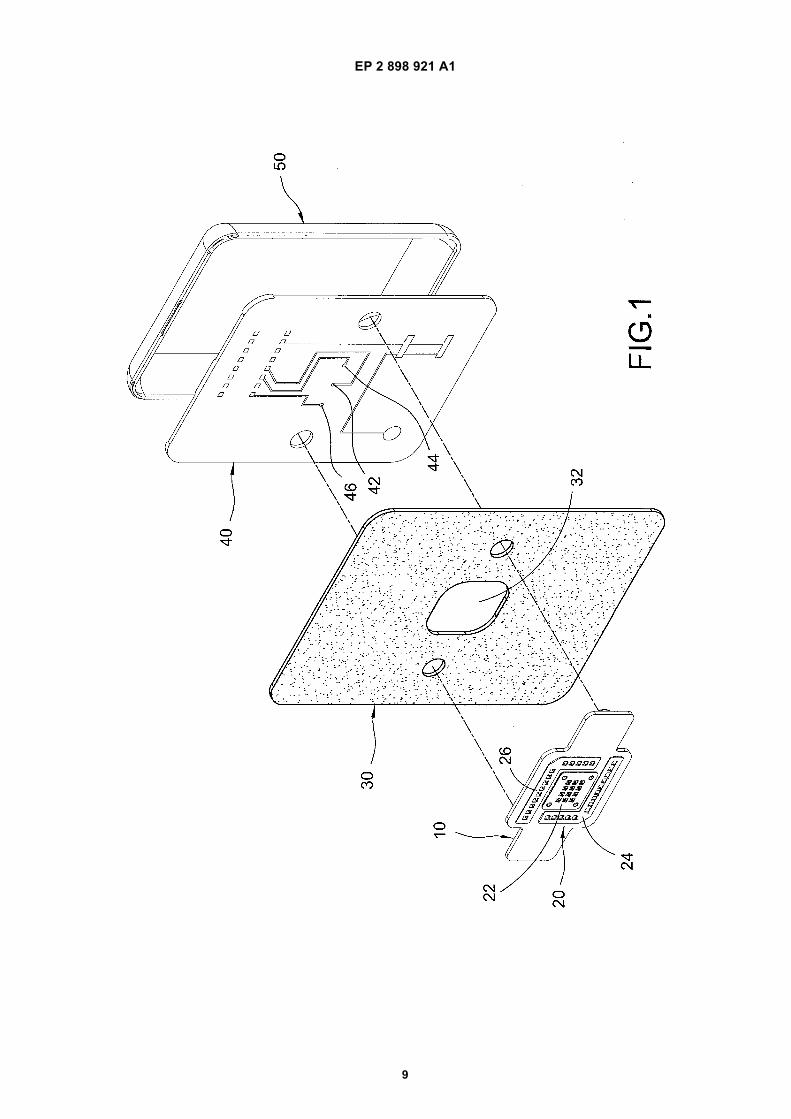
Fig. 1 shows the exploded view of the transdermalmicroneedles continuous monitoring system accord-ing to an embodiment of the present invention fromone viewing direction.
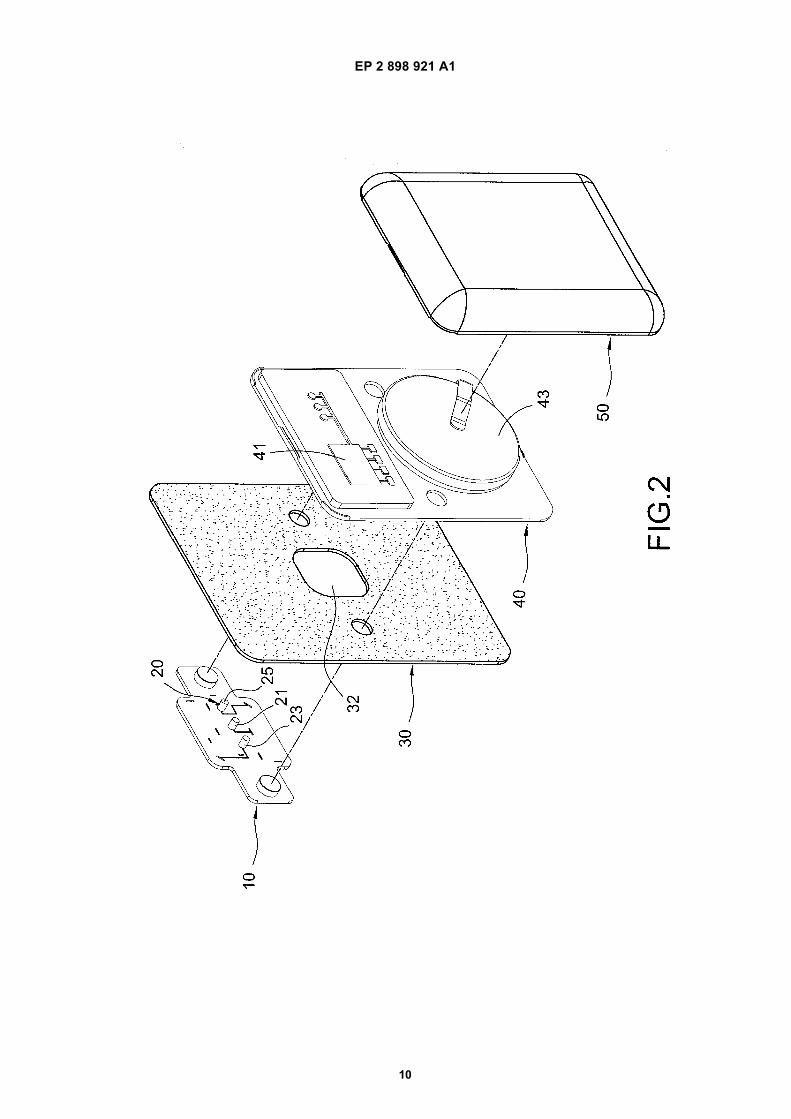
Fig. 2 shows the exploded view of the transdermalmicroneedles continuous monitoring system fromanother viewing direction.
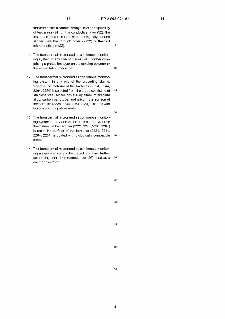
Fig. 3 shows a schematic exploded view of the micro-needle unit according to an embodiment of thepresent invention.
Fig. 4 is a top view of the microneedle set functioningas working electrode according to an embodimentof the present invention.
Fig. 5 is a top view of the microneedle set functioningas working electrode according to another embodi-ment of the present invention.
Fig. 6 is a top view of the microneedle set functioningas working electrode according to still another em-bodiment of the present invention.
Fig. 7 is a top view of the microneedle set functioningas working electrode according to still another em-bodiment of the present invention.
Fig. 8 shows a perspective of an assembledtransdermal microneedles continuous monitoringsystem according to an embodiment of the presentinvention.
Fig. 9 shows a sectional of an assembled transder-mal microneedles continuous monitoring system ac-cording to an embodiment of the present invention.
Fig. 10 is a partially sectional view of Fig. 9, wheresensing polymer is coated on the barbules.
Fig. 11 is a partially sectional view of Fig. 9, wheresensing polymer is coated on a test strip.
Fig. 12 shows a partially sectional view of an assem-bled transdermal microneedles continuous monitor-ing system according to another embodiment of thepresent invention.
DETAILED DESCRIPTION OF THE INVENTION
[0013] The features of the invention believed to be nov-el are set forth with particularity in the appended claims.The invention itself, however, may be best understoodby reference to the following detailed description of theinvention, which describes an exemplary embodiment ofthe invention, taken in conjunction with the accompany-ing drawings, in which:
Fig. 1 shows the exploded view of the transdermalmicroneedles continuous monitoring system accord-ing to an embodiment of the present invention fromone viewing direction, and Fig. 2 shows the explodedview of the transdermal microneedles continuousmonitoring system from another viewing direction.The transdermal microneedles continuous monitor-ing system of the present invention mainly comprisesa substrate 10, a microneedle unit 20, a flexible pad30, a signal processing unit 41, a power supply unit43 and a cover 50, where the signal processing unit41 and the power supply unit 43 are arranged on acircuit board 40.
[0014] According to an embodiment of the present in-vention, the microneedle unit 20 comprises a first micro-needle set 22 used as a working electrode, a secondmicroneedle set 24 used as a reference electrode, anda third microneedle set 26 used as a counter electrode.The flexible pad 30 has an opening 32 through which themicroneedle unit 20 passes. The microneedle unit 20 fur-ther comprises electric conducting posts 21, 23, 25 torespectively and electrically connect to the contacts 42,44 and 46 on the circuit board 40. The transdermal micro-needles continuous monitoring system of the present in-vention uses the flexible pad 30 to have tight fit with theuser’s muscle during operating thereof.[0015] The signal processing unit 41 electrically con-nects to the microneedle unit 20 and receives a concen-tration data of hypodermal target molecules sensed bythe microneedle unit 20. The signal processing unit 41generates a sensing signal manifesting the current phys-iological condition of user after processing the receivedconcentration data. The power supply unit 43 providesworking power to the transdermal microneedles contin-uous monitoring system of the present invention.[0016] Fig. 3 shows a schematic exploded view of themicroneedle unit 20 according to an embodiment of thepresent invention. The first microneedle set 22 comprisesa first sheet 222 and a second sheet 224 stacked withthe first sheet 222. The first sheet 222 has at least onefirst through hole 2222 defined thereon, and a first bar-bule 2224 at peripheral of the first through hole 2222.The second sheet 224 has at least one second throughhole 2242 defined thereon, and a second barbule 2244at peripheral of the second through hole 2242, where thesecond barbule 2244 penetrates the first through hole2222 to juxtapose the first barbule 2224. The second
3 4

EP 2 898 921 A1
4
5
10
15
20
25
30
35
40
45
50
55
sheet 224 of the first microneedle set 22 comprises barb2246 at the peripheral thereof and matched with the ap-erture 102 defined on the substrate 10. According to an-other embodiment, the second sheet 224 of the firstmicroneedle set 22 comprises conductive pin 2248 at theperipheral thereof. The conductive pin 2248 can be in-serted into a slot 104 defined on the substrate 10 to elec-trically connect to the conductive post 21.[0017] Similarly, the second microneedle set 24 com-prises a first sheet 242. The first sheet 242 has at leastone first through hole 2422 defined thereon, and a firstbarbule 2424 at peripheral of the first through hole 2422.The first sheet 242 of the second microneedle set 24comprises barb 2426 at the peripheral thereof andmatched with the aperture 102 defined on the substrate10. According to another embodiment, the first sheet 242of the second microneedle set 24 comprises conductivepin 2428 at the peripheral thereof. The conductive pin2428 can be inserted into a slot 104 defined on the sub-strate 10 to electrically connect to the conductive post 23.[0018] Similarly, the third microneedle set 26 also com-prises a first sheet 262. The first sheet 262 has at leastone first through hole 2622 defined thereon, and a firstbarbule 2624 at peripheral of the first through hole 2622.The first sheet 262 of the third microneedle set 26 com-prises barb 2626 at the peripheral thereof and matchedwith the aperture 102 defined on the substrate 10. Ac-cording to another embodiment, the first sheet 262 of thethird microneedle set 26 comprises conductive pin 2628at the peripheral thereof. The conductive pin 2628 canbe inserted into a slot 104 defined on the substrate 10 toelectrically connect to the conductive post 25.[0019] According to an embodiment of the present in-vention, the first microneedle set 22, the second micro-needle set 24, and the third microneedle set 26 can bemade by punching or etching process. The material ofthe barbules is selected from the group consisting ofstainless steel, nickel, nickel alloy, titanium, titanium al-loy, carbon nanotube, and silicon. The surface of the bar-bules is coated with biologically compatible metal. Thematerial of the barbules can also be selected from thegroup consisting of polycarbonate, polymethacrylic acid,polytetrafluoroethylene, and polyester. The surface ofthe barbules is also coated with biologically compatiblemetal. Moreover, the height of the barbules is 300-600micrometers; the base width of the barbules is 150-450micrometers. The separation between tips of the bar-bules is 500-3000 micrometers.[0020] With reference to Figs. 4 to 7, Fig. 4 is a topview of the microneedle set functioning as working elec-trode according to an embodiment of the present inven-tion. The first microneedle set 22 comprises a first sheet222 and a second sheet 224 stacked with the first sheet222. The first sheet 222 has at least one first throughhole 2222 defined thereon, and a first barbule 2224 atperipheral of the first through hole 2222. The secondsheet 224 has at least one second through hole 2242defined thereon, and a second barbule 2244 at peripheral
of the second through hole 2242, where the second bar-bule 2244 penetrates the first through hole 2222 to jux-tapose the first barbule 2224.[0021] Fig. 5 is a top view of the microneedle set func-tioning as working electrode according to another em-bodiment of the present invention. The first microneedleset 22 comprises a first sheet 222, a second sheet 224and a third sheet 226 stacked with each other. The firstsheet 222 has at least one first through hole 2222 definedthereon, and a first barbule 2224 at peripheral of the firstthrough hole 2222. The second sheet 224 has at leastone second through hole 2242 defined thereon, and asecond barbule 2244 at peripheral of the second throughhole 2242. The third sheet 226 has at least one thirdthrough hole 2262 defined thereon, and a third barbule2264 at peripheral of the third through hole 2262. Thesecond barbule 2244 and the third barbule 2264 pene-trates the first through hole 2222 to juxtapose the firstbarbule 2224, and the tips of the barbules are in righttriangular arrangement from top view.[0022] Fig. 6 is a top view of the microneedle set func-tioning as working electrode according to still anotherembodiment of the present invention. The first micronee-dle set 22 comprises a first sheet 222, a second sheet224 and a third sheet 226 stacked with each other. Thefirst sheet 222 has at least one first through hole 2222defined thereon, and a first barbule 2224 at peripheral ofthe first through hole 2222. The second sheet 224 hasat least one second through hole 2242 defined thereon,and a second barbule 2244 at peripheral of the secondthrough hole 2242. The third sheet 226 has at least onethird through hole 2262 defined thereon, and a third bar-bule 2264 at peripheral of the third through hole 2262.The second barbule 2244 and the third barbule 2264 pen-etrates the first through hole 2222 to juxtapose the firstbarbule 2224, and the tips of the barbules are in isoscelestriangular arrangement from top view.[0023] Fig. 7 is a top view of the microneedle set func-tioning as working electrode according to still anotherembodiment of the present invention. The first micronee-dle set 22 comprises a first sheet 222, a second sheet224, a third sheet 226 and a fourth sheet 228 stackedwith each other. The first sheet 222 has at least one firstthrough hole 2222 defined thereon, and a first barbule2224 at peripheral of the first through hole 2222. Thesecond sheet 224 has at least one second through hole2242 defined thereon, and a second barbule 2244 at pe-ripheral of the second through hole 2242. The third sheet226 has at least one third through hole 2262 defined ther-eon, and a third barbule 2264 at peripheral of the thirdthrough hole 2262. The fourth sheet 228 has at least onefourth through hole 2282 defined thereon, and a fourthbarbule 2284 at peripheral of the fourth through hole2282. The second barbule 2244, the third barbule 2264and the fourth barbule 228 penetrates the first throughhole 2222 to juxtapose the first barbule 2224, and thetips of the barbules are in rectangular arrangement fromtop view.
5 6

EP 2 898 921 A1
5
5
10
15
20
25
30
35
40
45
50
55
[0024] In the embodiments shown in Figs. 4 to 7, thebarbule 2224 of the first microneedle set 22 comprisesa tip 2221 and a base 2223. The tips of those barbules,after the sheets are stacked together, are not at the samealtitudes. Namely, some barbules pass more throughholes than other barbules. Alternatively, the height of thebarbules can be such designed, based on the stackedorder of sheets, that the tips of those barbules, after thesheets are stacked together, are at the same altitudes.[0025] Fig. 8 shows a perspective of an assembledtransdermal microneedles continuous monitoring sys-tem according to an embodiment of the present invention.Fig. 9 shows a sectional of an assembled transdermalmicroneedles continuous monitoring system accordingto an embodiment of the present invention. In this shownembodiment, the first microneedle set 22 comprises afirst sheet 222 and a second sheet 224 stacked with eachother. The first sheet 222 and the second sheet 224 canbe assembled by punching peripherals thereof. The sec-ond microneedle set 24 comprises only a first sheet 242and the third microneedle set 26 comprises only a firstsheet 262. The transdermal microneedles continuousmonitoring system of the present invention uses the flex-ible pad 30 to have tight fit with the user’s muscle duringoperation thereof.[0026] Fig. 10 is a partially sectional view of Fig. 9,where sensing polymer is coated on the barbules. Moreparticularly, the sensing polymer is coated on the innerfaces of the barbules, and anti-irritation medicine (med-icine preventing skin from irritation) is coated on outerfaces of the barbules. In this embodiment, the sensingpolymer is a molecule selected from the group consistingof an antibody, an aptamer, a single-chain variable frag-ment (ScFv), a carbohydrate, glucose oxidase (GOx),hydroxybutyrate dehydrogenase (HBHD), and a combi-nation thereof. The transdermal microneedles continu-ous monitoring system having barbules coated with thesensing polymer can sense the concentration data of hy-podermal target molecules and determine the currentphysiological condition of user with the concentration da-ta.[0027] Fig. 11 is a partially sectional view of Fig. 9,where sensing polymer is coated on a test strip. The em-bodiment shown in this figure is different with the embod-iment of Fig. 10 in that the first microneedle set 22 in thisembodiment is used to withdraw interstitial fluid. There-fore, the sensing polymer is coated on a test strip belowthe first microneedle set 22 instead of coating on the bar-bules. In this embodiment, the test strip is arranged be-tween the first microneedle set 22 and the substrate 10.The test strip comprises a conductive layer 92 and a plu-rality of test areas 94 on the conductive layer 92. Thetest areas 94 are coated with sensing polymer andaligned with the through holes 2222 of the first micronee-dle set 22. In this embodiment, the test areas 94 aredefined by the resin plate 96. Moreover, the first micro-needle set 22 is fixed to the test strip by a binding layer98. In order to prevent the sensing polymer and the anti-
irritation medicine from environment pollution, a protec-tion layer such as an epoxy-polyurethane (Epoxy-PU)film is formed on the surface of the sensing polymer andthe anti-irritation medicine.[0028] Fig. 12 shows a partially sectional view of anassembled transdermal microneedles continuous moni-toring system according to another embodiment of thepresent invention. In this embodiment, the conductive pin2248 is bent to electrically connect the contact 42 on thecircuit board 40, thus dispensing with the conductivepost.
Claims
1. A transdermal microneedles continuous monitoringsystem, comprising:
a substrate (10);a microneedle unit (20) comprising at least a firstmicroneedle set (22) used as working electrodeand a second microneedle set (24) used as ref-erence electrode, each of the microneedle setcomprising at least a microneedle, the firstmicroneedle set (22) comprising at least a sheet(222), the sheet (222) having a through hole(2222) defined thereon and a barbule (2224) ar-ranged at the peripheral of the through hole(2222), the through hole (2222) on one sheetallowing the corresponding barbules of othersheet to pass and the barbules being disposedseparately;a signal processing unit (41) arranged on thesubstrate (10) and electrically connecting to thefirst microneedle set (22) and the second micro-needle set (24); anda power supply unit (43) providing working pow-er to the transdermal microneedles continuousmonitoring system.
2. The transdermal microneedles continuous monitor-ing system in claim 1, wherein the first microneedleset (22) comprises a first sheet (222) and a secondsheet (224) stacked with the first sheet (222), thefirst sheet (222) having at least one first through hole(2222) defined thereon, and a first barbule (2224) atperipheral of the first through hole (2222), the secondsheet (224) having at least one second through hole(2242) defined thereon and a second barbule (2244)at peripheral of the second through hole (2242),wherein the second barbule (2244) penetrates thefirst through hole (2222) to juxtapose the first barbule(2224) at corresponding location.
3. The transdermal microneedles continuous monitor-ing system in claim 1, wherein the first microneedleset (22) comprises a first sheet (222), a second sheet(224) and a third sheet (226) stacked with each other,
7 8

EP 2 898 921 A1
6
5
10
15
20
25
30
35
40
45
50
55
the first sheet (222) having at least one first throughhole (2222) defined thereon, and a first barbule(2224) at peripheral of the first through hole (2222),the second sheet (224) having at least one secondthrough hole (2242) defined thereon and a secondbarbule (2244) at peripheral of the second throughhole (2242), the third sheet (226) having at least onethird through hole (2262) defined thereon and a thirdbarbule (2264) at peripheral of the third through hole(2262), wherein the second barbule (2244) and thethird barbule (2264) penetrate the first through hole(2222) to juxtapose the first barbule (2224), and tipsof the barbules (2224, 2244, 2264) are in triangulararrangement.
4. The transdermal microneedles continuous monitor-ing system in claim 1, wherein the first microneedleset (22) comprises a first sheet (222), a second sheet(224), a third sheet (226) and a fourth sheet (228)stacked with each other, the first sheet (222) havingat least one first through hole (2222) defined thereon,and a first barbule (2224) at peripheral of the firstthrough hole (2222), the second sheet (224) havingat least one second through hole (2242) defined ther-eon and a second barbule (2244) at peripheral of thesecond through hole (2242), the third sheet (226)having at least one third through hole (2262) definedthereon and a third barbule (2264) at peripheral ofthe third through hole (2262), the fourth sheet (228)having at least one fourth through hole (2282) de-fined thereon and a fourth barbule (2284) at periph-eral of the fourth through hole (2282), wherein thesecond barbule (2244), the third barbule (2264) andthe fourth barbule (2284) penetrate the first throughhole (2222) to juxtapose the first barbule (2224), andtips of the barbules (2224, 2244, 2264, 2284) are inrectangular arrangement.
5. The transdermal microneedles continuous monitor-ing system in any one of claims 1-4, wherein eachof the barbule (2224) of the first microneedle set (22)comprises a tip (2221) and a base (2223), whereintips of the barbules are not at the same altitudes afterthe sheets are stacked and the through hole of onesheet are penetrated by the barbules of other sheets.
6. The transdermal microneedles continuous monitor-ing system in any one of claims 1-4, wherein eachof the barbule (2224) of the first microneedle set (22)comprises a tip (2221) and a base (2223), whereinthe tips of the barbules are at the same altitudes afterthe sheets are stacked and the through hole of onesheet are penetrated by the barbules of other sheets.
7. The transdermal microneedles continuous monitor-ing system in any one of the preceding claims,wherein the microneedles of first microneedle set(22) and the second microneedle set (24) are formed
by punching or etching.
8. The transdermal microneedles continuous monitor-ing system in any one of the preceding claims,wherein each the barbules (2224) has sensing pol-ymer coated on inner surface thereof.
9. The transdermal microneedles continuous monitor-ing system in any one of the preceding claims,wherein each the barbules (2224) has anti-irritationmedicine coated on outer surface thereof.
10. The transdermal microneedles continuous monitor-ing system in any one of the preceding claims, furthercomprising a test strip arranged between the firstmicroneedle set (22) and the substrate (10), the teststrip comprises a conductive layer (92) and a pluralityof test areas (94) on the conductive layer (92), thetest areas (94) are coated with sensing polymer andaligned with the through holes (2222) of the firstmicroneedle set (22).
11. The transdermal microneedles continuous monitor-ing system in any one of claims 8-10, further com-prising a protection layer on the sensing polymer orthe anti-irritation medicine.
12. The transdermal microneedles continuous monitor-ing system in any one of the preceding claims,wherein the material of the barbules (2224, 2244,2264, 2284) is selected from the group consisting ofstainless steel, nickel, nickel alloy, titanium, titaniumalloy, carbon nanotube, and silicon, the surface ofthe barbules (2224, 2244, 2264, 2284) is coated withbiologically compatible metal.
13. The transdermal microneedles continuous monitor-ing system in any one of the claims 1-11, whereinthe material of the barbules (2224, 2244, 2264, 2284)is resin, the surface of the barbules (2224, 2244,2264, 2284) is coated with biologically compatiblemetal.
14. The transdermal microneedles continuous monitor-ing system in in any one of the preceding claims,further comprising a third microneedle set (26) usedas a counter electrode.
Amended claims in accordance with Rule 137(2)EPC.
1. A transdermal microneedles continuous monitoringsystem, comprising:
a substrate (10);a microneedle unit (20) comprising at least a firstmicroneedle set (22) used as working electrode
9 10
EP 2 898 921 A1
7
5
10
15
20
25
30
35
40
45
50
55
and a second microneedle set (24) used as ref-erence electrode, each of the microneedle setcomprising at least one microneedle;a signal processing unit (41) arranged on thesubstrate (10) and electrically connecting to thefirst microneedle set (22) and the second micro-needle set (24); anda power supply unit (43) providing working pow-er to the transdermal microneedles continuousmonitoring system,
characterized in that said first microneedle set (22)comprises a plurality of sheets (222, 224, 226, 228)stacked with each other, each of the sheets (222,224, 226, 228) having at least one through hole(2222, 2242, 2262, 2282) defined thereon and a bar-bule (2224, 2244, 2264, 2284) arranged at the pe-ripheral of the through hole (2222, 2242, 2262,2282), wherein the through hole (2222) on one sheet(222) is penetrated by the barbules (2244, 2264,2284) of other sheets (224, 226, 228) and the bar-bules (2224, 2244, 2264, 2284) are being disposedseparately.
2. The transdermal microneedles continuous monitor-ing system in claim 1, wherein the first microneedleset (22) comprises a first sheet (222) and a secondsheet (224) stacked with the first sheet (222), thefirst sheet (222) having at least one first through hole(2222) defined thereon, and a first barbule (2224) atperipheral of the first through hole (2222), the secondsheet (224) having at least one second through hole(2242) defined thereon and a second barbule (2244)at peripheral of the second through hole (2242),wherein the second barbule (2244) penetrates thefirst through hole (2222) to juxtapose the first barbule(2224) at corresponding location.
3. The transdermal microneedles continuous monitor-ing system in claim 1, wherein the first microneedleset (22) comprises a first sheet (222), a second sheet(224) and a third sheet (226) stacked with each other,the first sheet (222) having at least one first throughhole (2222) defined thereon, and a first barbule(2224) at peripheral of the first through hole (2222),the second sheet (224) having at least one secondthrough hole (2242) defined thereon and a secondbarbule (2244) at peripheral of the second throughhole (2242), the third sheet (226) having at least onethird through hole (2262) defined thereon and a thirdbarbule (2264) at peripheral of the third through hole(2262), wherein the second barbule (2244) and thethird barbule (2264) penetrate the first through hole(2222) to juxtapose the first barbule (2224), and tipsof the barbules (2224, 2244, 2264) are in triangulararrangement.
4. The transdermal microneedles continuous monitor-
ing system in claim 1, wherein the first microneedleset (22) comprises a first sheet (222), a second sheet(224), a third sheet (226) and a fourth sheet (228)stacked with each other, the first sheet (222) havingat least one first through hole (2222) defined thereon,and a first barbule (2224) at peripheral of the firstthrough hole (2222), the second sheet (224) havingat least one second through hole (2242) defined ther-eon and a second barbule (2244) at peripheral of thesecond through hole (2242), the third sheet (226)having at least one third through hole (2262) definedthereon and a third barbule (2264) at peripheral ofthe third through hole (2262), the fourth sheet (228)having at least one fourth through hole (2282) de-fined thereon and a fourth barbule (2284) at periph-eral of the fourth through hole (2282), wherein thesecond barbule (2244), the third barbule (2264) andthe fourth barbule (2284) penetrate the first throughhole (2222) to juxtapose the first barbule (2224), andtips of the barbules (2224, 2244, 2264, 2284) are inrectangular arrangement.
5. The transdermal microneedles continuous monitor-ing system in any one of claims 1-4, wherein eachof the barbule (2224) of the first microneedle set (22)comprises a tip (2221) and a base (2223), whereintips of the barbules are not at the same altitudes afterthe sheets are stacked and the through hole of onesheet are penetrated by the barbules of other sheets.
6. The transdermal microneedles continuous monitor-ing system in any one of claims 1-4, wherein eachof the barbule (2224) of the first microneedle set (22)comprises a tip (2221) and a base (2223), whereinthe tips of the barbules are at the same altitudes afterthe sheets are stacked and the through hole of onesheet are penetrated by the barbules of other sheets.
7. The transdermal microneedles continuous monitor-ing system in any one of the preceding claims,wherein the microneedles of first microneedle set(22) and the second microneedle set (24) are formedby punching or etching.
8. The transdermal microneedles continuous monitor-ing system in any one of the preceding claims,wherein each the barbules (2224) has sensing pol-ymer coated on inner surface thereof.
9. The transdermal microneedles continuous monitor-ing system in any one of the preceding claims,wherein each the barbules (2224) has anti-irritationmedicine coated on outer surface thereof.
10. The transdermal microneedles continuous monitor-ing system in any one of the preceding claims, furthercomprising a test strip arranged between the firstmicroneedle set (22) and the substrate (10), the test
11 12
EP 2 898 921 A1
8
5
10
15
20
25
30
35
40
45
50
55
strip comprises a conductive layer (92) and a pluralityof test areas (94) on the conductive layer (92), thetest areas (94) are coated with sensing polymer andaligned with the through holes (2222) of the firstmicroneedle set (22),
11. The transdermal microneedles continuous monitor-ing system in any one of claims 8-10, further com-prising a protection layer on the sensing polymer orthe anti-irritation medicine.
12. The transdermal microneedles continuous monitor-ing system in any one of the preceding claims,wherein the material of the barbules (2224, 2244,2264, 2284) is selected from the group consisting ofstainless steel, nickel, nickel alloy, titanium, titaniumalloy, carbon nanotube, and silicon, the surface ofthe barbules (2224, 2244, 2264, 2284) is coated withbiologically compatible metal.
13. The transdermal microneedles continuous monitor-ing system in any one of the claims 1-11, whereinthe material of the barbules (2224, 2244, 2264, 2284)is resin, the surface of the barbules (2224, 2244,2264, 2284) is coated with biologically compatiblemetal.
14. The transdermal microneedles continuous monitor-ing system in any one of the preceding claims, furthercomprising a third microneedle set (26) used as acounter electrode.
13 14
EP 2 898 921 A1
9
EP 2 898 921 A1
10

EP 2 898 921 A1
11

EP 2 898 921 A1
12

EP 2 898 921 A1
13

EP 2 898 921 A1
14

EP 2 898 921 A1
15

EP 2 898 921 A1
16

EP 2 898 921 A1
17

EP 2 898 921 A1
18

EP 2 898 921 A1
19
5
10
15
20
25
30
35
40
45
50
55
EP 2 898 921 A1
20
5
10
15
20
25
30
35
40
45
50
55
EP 2 898 921 A1
21
5
10
15
20
25
30
35
40
45
50
55

EP 2 898 921 A1
22
5
10
15
20
25
30
35
40
45
50
55

EP 2 898 921 A1
23
REFERENCES CITED IN THE DESCRIPTION
This list of references cited by the applicant is for the reader’s convenience only. It does not form part of the Europeanpatent document. Even though great care has been taken in compiling the references, errors or omissions cannot beexcluded and the EPO disclaims all liability in this regard.
Patent documents cited in the description
• US 7344499 B [0005]


![(19) TZZ¥ ¥ T - patentimages.storage.googleapis.com · EP3 238 724A2 2 5 10 15 20 25 30 35 40 45 50 55 Description PRIORITY [0001] This application claims priority to U.S. Provisional](https://img.pdfslide.us/doc/110x75/5b83d1dd7f8b9a31608e23a0/19-tzz-t-ep3-238-724a2-2-5-10-15-20-25-30-35-40-45-50-55-description.jpg)


![(19) TZZ Z¥ T - patentimages.storage.googleapis.com · [0002] Circumdental wiring techniques include metal-lic wires that are placed around one or more teeth and ... tient’s jaws](https://img.pdfslide.us/doc/110x75/5b9a2bb609d3f26e678d845f/19-tzz-z-t-0002-circumdental-wiring-techniques-include-metal-lic-wires.jpg)

![(19) TZZ¥Z T - patentimages.storage.googleapis.com · [0017] The dosage regimen of the present invention is a regimen for a S1P receptor modulator or agonist therapy, ... or disease,](https://img.pdfslide.us/doc/110x75/5adca6477f8b9aa5088bc2ff/19-tzzz-t-0017-the-dosage-regimen-of-the-present-invention-is-a-regimen-for.jpg)
![(19) TZZ Z T - patentimages.storage.googleapis.com · [0035] sali t Iso desirable toreduc e asm uch as possible the use ofal rge cranes andoth f e drawworksof rar sing i he t mast](https://img.pdfslide.us/doc/110x75/5c1621b509d3f25e0b8bf8a7/19-tzz-z-t-0035-sali-t-iso-desirable-toreduc-e-asm-uch-as-possible-the.jpg)
![(19) TZZ T - patentimages.storage.googleapis.com · nia rato iranging from8% to 25% by weightand impurtiesi ranging from 0% to 5% by weight. [0004] The ... mula CaSO 4.2H 2O or of](https://img.pdfslide.us/doc/110x75/5badafc409d3f2251e8befb5/19-tzz-t-nia-rato-iranging-from8-to-25-by-weightand-impurtiesi-ranging.jpg)
![(19) TZZ ¥ T - patentimages.storage.googleapis.com · [0016] Inthe preferred embodimentsth e above- descrbed i methodsacc ordnigto th epr esentni venton i furtherc omprse:i reporting](https://img.pdfslide.us/doc/110x75/5c41ea6493f3c338dc2648aa/19-tzz-t-0016-inthe-preferred-embodimentsth-e-above-descrbed-i-methodsacc.jpg)


![(19) TZZ Z T - patentimages.storage.googleapis.com · between the cap 52 and a shoulder 56a of piston carrier 56. [0022] A piston or plunger 60 is affixed to extension rod 56b, e.g](https://img.pdfslide.us/doc/110x75/5c27af8a09d3f240638b68a2/19-tzz-z-t-between-the-cap-52-and-a-shoulder-56a-of-piston-carrier-56-0022.jpg)