Embed Size (px)
Citation preview

180 JEEE TRANSACTIONS ON VEHICULAR TECHNOLOGY, VOL. 45, NO 1, FEBRUARY 1996
wed Permanent agnet MO tor r Battery-Powered Electric Ve
C. C. Chan and K. T. Chau
Abstract-Recent availability of high-energy neodymium-iron- boron (Nd-Fe-B) permanent magnet (PM) material has focused attention on the use of the PM synchronous motor (PMSM) drive for electric vehicles (EV's). A new Nd-Fe-B PMSM is proposed for the drive system, which possesses high power density and high efficiency, resulting in greater energy and space savings. The design and optimization of the motor employ finite element anal- ysis and computer graphics. Increasingly, a new PWM inverter algorithm is developed for the drive system, which can handle the nonconstant battery voltage source. An efficiency optimizing control is adopted to further improve the energy utilization of the drive system. Both the control strategy and the PWM generation are implemented in a single-chip microcontroller. As a result, the motor drive achieves high power density, high efficiency, and compactness. A prototype of the 3.2-kW battery-powered drive system has been designed and built for an experimental mini-EV.
I. INTRODUCTION
N the past decades, dc variable-speed drive systems were commonly used for industrial drive and electric vehicle
(EV) applications. Studies [1]-[4] have shown that an ac drive system offers several definite advantages over dc drive systems for EV's, among which are these:
1) light weight and high efficiency, 2) efficient regenerative braking, 3) robustness and reliability, and 4) almost maintenance free. In recent years, the International Electric Vehicle Research
Center has launched a series of research projects on the deveIopment of advanced EV's with an ac propulsion system [5]. The projects of the electric sedan [6] and electric van [7] have been concentrated on the deve€opment of advanced control strategies with the application of standard construction induction motors. On the other hand, the high-efficiency, high power density special motor drives are undergoing develop- ment for EV applications.
Recent research has indicated that the permanent magnet (PM) ac motors, which include the PM synchronous motor (PMSM) and the brushless dc motor (BDCM) and inherently possess high efficiency and high power density, are becoming attractive in high-performance drive systems and have the prospect to compete in the induction motor market [8]-[lo]. Although the PMSM and the BDCM are similar in con-
struction, their mathematical models, hence steady-state and dynamic behaviors, are different [ 1 11.
The PMSM has a sinusoidal back EMF and requires sinu- soidal stator currents to produce constant torque, while the BDCM has a trapezoidal back EMF and requires rectangular stator currents to produce constant torque. In general, the PMSM is very similar to the standard wound rotor syn- chronous motor except that the excitation is provided by a magnet instead of a field winding. Since there is no difference between the back EMF produced by a magnet and that pro- duced by an excited coil, the mathematical model of a PMSM is also similar to that of a wound rotor synchronous motor. As the transformation of the synchronous machine equations from the A-B-C phase variables to the 0 - Q variables forces all sinusoidally varying inductances in the A-B-C frame to become constant in the 0 - Q frame, the 0 - Q model of the PMSM can be derived. On the contrary, since the back EMF in the BDGM is nonsinusoidal, the inductances do not vary sinusoidally in the A-B-C frame, and it does not seem advantageous to transform the equations to the 0-Q frame since the inductances will not be constant after transformation. Hence the A-B-C phase variables model is used for the BDCM.
The BDCM must be operated in the closed-loop mode where a relatively expensive and delicate rotor position sensor is always used, even though many attempts have been made to eliminate this sensor to facilitate the commutation of the power converter. Its speed control is generally accomplished by regulating the applied voltage. This motor has a significant torque pulsation due to the commutating current during the phase commutation of the switching devices. On the contrary, the PMSM can be operated in either the open-loop mode or the closed-loop mode where the rotor position sensor may be used only when some sophisticated control strategies are implemented. Similar to a wound rotor synchronous motor, the rotor of the PMSM is always in synchronism with the rotating field, which depends on the applied frequency. Similar to the classical polyphase ac motors, namely the synchronous motor and the induction motor, the PMSM produces an essentially constant instantaneous torque or so-called smooth torque [ 121.
Being fueled by rapid developments in high-energy magnet material technology [ 131, [ 141, modern computation methods
Manuscript received November 30, 1991; revised March 15, 1995. A brief for L i 5 i 3 [I6], and powerful 'Omput- version of this paper was presented at the 10th IntematlonaI Electric Vehicle ing enVirOm" [17], [l8], numerous motor geometries of the Symposium, Hong Kong
ing, University of Hong Kong, Pokfulam Road, Hong Kong
PMSM have been designed. In general, the design philoso- phy is to further improve the power density and efficiency The authors are with the Department of Electncal and Electronic Engineer-
Publisher Item Identlfier Sh018-9545(96)00196-X~ by adopting either flux enhancement [ 101, armature-reaction
0018-9545/96$05.00 0 1996 IEEE

CHAN AND CHAU: PERMANENT MAGNET MOTOR DRITIE FOR BATTERY-POWERED ELECTRIC VEHICLES 181
TABLE I SPECIFICATIONS OF MINI-EV
Vehicle Gross Weight: 403 kg Normal Payload: 200 kg Top Speed: 30 km/h Gradability: 15" Acceleration: 8 s (0 - 20 h / h ) Range: 70 km (20 km/h constant) Battery: 4 X 12 V 75 Ah lead acid
reduction, or high-speed operation. In this paper, a newly designed PMSM with special rotor geometry is developed, which is suitable for EV applications. Since the magnet material is relatively expensive, in practice, it may not be economical to design the PMSM at a very high power range. However, the required output power of a mini-EV is of several kilowatts, which is a suitable power range for economical application of the PMSM.
For battery-powered EV's, the energy stored in the battery becomes so precious that a high-efficiency drive system is of the utmost importance. Besides using the PMSM to improve the energy utilization of the drive system, an efficiency op- timizing control scheme is adopted [19], [20]. The control strategy operates by measuring the curreni. on the dc link and adjusting the voltage output of the inverter to minimize this quantity. In this way, the system optimizes the combined motor-inverter efficiency, not just the motor efficiency. Since the control strategy requires the output voltage and efficiency to be individually controllable, a voltage-controlled voltage- source PWM inverter is used. However, the voltage level of the battery fluctuates significantly, which depends on the battery state-of-charge, discharging current, temperature, and aging. Conventionally, in order to compensate for such fluctuation, an additional pulsewidth compensator unit is installed. Instead of using an additional unit, a new PWM algorithm, namely the equal-area pulsewidth modulation (EAPWM ), is proposed and implemented, which can handle a changiqg battery voltage [211.
Owing to the increasing demands impos1:d on knowledge of critical areas and tools for design and optimization, the electromagnetic field approach to the design of electrical machines has been widely accepted. As the finite element method (FEM) is regarded as one of the most powerful tools in electromagnetic field analysis [22], it is adopted to design and optimize the proposed PMSM. Since the mathematical model of a PMSM is similar to that of a wound rotor synchronous motor, the PMSM is modeled by using the standard synchronous machine equivalent circuit.
11. DRIVE SYSTEM
The off-road mini-EV is designed for use in areas without many steep roads, hence its range per charge is most essential while it is still capable of climbing a :$light ramp. The
Fig. 1. Experimental mini-EV.
w
Fig. 2. Functional block diagram
experimental mini-EV is shown in Fig. 1, and its specifications are listed in Table I.
The functional block diagram of the mini-EV is illustrated in Fig. 2. The PWM inverter converts the battery pack dc voltage into a variable-voltage, variable-frequency PWM voltage for the three-phase PMSM. The motor then drives the wheels through a two-speed gear box. The controller gathers command from the driver and feedback information from the system, and then provides switching signals to the inverter according to the desired control strategy.
111. PM SYNCHRONOUS MOTOR
A. Motor Geometry Starting from the last decade, numerous geometries of the
PMSM have been introduced. They are usually based on the further imlprovements of power density and efficiency by adopting either flux enhancement, armature-reaction reduction, or high-speed operation. Electrical motors should be operated

182 E E E TRANSACTIONS ON VEHICULAR TECHNOLOGY, VOL. 45, NO. 1, FEBRUARY 1996
at an air-gap flux density of about 0.8 T to achieve high efficiency, and an iron-core flux density of about 1.2 T to ensure good utilization of laminated iron cores. The flux- enhancement arrangement of the PMSM allows higher flux densities in the air-gap and enables the operating point of the magnets to be shifted toward the optimum, which leads to the saving in relatively expensive magnet materials. However, with the employment of flux enhancement, the effective air- gap (including the actual air-gap and the magnets) to be bridged by the armature field is usually very small, leading to a strong armature reaction. This leads to limit the attainable average force density of the PMSM. Moreover, due to the high armature reactance of the PMSM, the operating performance of the inverter is degraded. In [23], a technique of using appropriately laminated iron poles to reduce the armature reaction was furnished. It is well known that the power density of electrical motors can be significantly increased by using a higher operating speed. By burying the magnets inside the rotor, they are then physically protected. Thus, under high- speed operation, the mechanical integrity of the rotor can be maintained.
The proposed PMSM, adopting a high-energy neodymium- iron-boron (Nd-Fe-B) magnet material and a new rotor ge- ometry, is shown in Fig. 3. In conjunction with the flux- enhancement arrangement, the armature reaction can be con- siderably reduced by making air slots symmetrically along the D-axes within the rotor. It is due to the fact that the air slot at each pole center has to be bridged by the m a t u r e field while the flux path for the excitation field has only an insignificant change. To avoid any serious harmonic distortion in the air-gap flux, a closed air slot is used. Due to the fact that the magnets are buried inside the rotor and are physically protected, a high-speed operation is permissible. Therefore, the proposed motor geometry allows the simultaneous attainments of flux enhancement, armature-reaction reduction, and high- speed operation, resulting in higher power density and higher efficiency.
B. Analysis and Optimization As the proposed PMSM has an unconventional rotor ge-
ometry and uses materials with anisotropic andfor nonlinear properties, electromagnetic design approach is necessary. The electromagnetic analysis can also give much greater knowl- edge of critical areas of the PMSM and provide a tool for optimization. Nowadays, the FEM, which was originally proposed by Silvester and Chari [221, is regarded as one of the most powerful tools in electromagnetic analysis of electrical machines. By solving the following nonlinear partial differential equation with proper boundary conditions
where A is the vector magnetic potential, p is the magnetic permeability, and J is the current density, while other field quantities can then be easily derived from the vector magnetic potentials. With the employment of FEM for electromagnetic calculation and computer graphics for solid modeling, anima- tion, pre- and post-processing of the massive database [17],
Fig. 3. Proposed rotor configuration.
[18], a computer-aided design software for the PMSM is developed in a powerful workstation [24]. The magnetic field distributions due to the magnet, D-axis armature reaction and Q-axis armature reaction are colorfully and interactively eval- uated. The field pattern is not only represented by using colors and intensities, its actual value of flux density corresponding to the location pointed by the on-line cursor is also displayed. Black-and-white photos of the magnetic field distributions of the PMSM are shown in Fig. 4.
The optimization of the proposed PMSM includes the "ization of magnet material outlay, as well as the max- imization of iron-core utilization, and the reduction of ar- mature reaction in conjunction with the arrangement of flux enhancement. Moreover, the magnet operating point on its demagnetizing curve should be considered so that it must refrain from demagnetization during starting or heavy loading conditions. The optimization flowchart is illustrated in Fig. 5. Focusing on the purposely introduced air slots, the shapes and dimensions are iteratively optimized. From Table 11, it can be found that the Q-axis armature reaction can be effectively reduced by a factor of 3.0 without a sacrifice of induced EMF. In conjunction with the flux enhancement, an air-gap flux density is of 0.8 T.
C. Specijcations The specifications of the three-phase, four-pole PMSM
specially designed for a battery-powered EV drive system are listed as follows:
Rated voltage 32 V
Rated output power 3.2 kW
Rated speed 4800 rpm
Rated efficiency 88.4%
Rated power factor 0.935
Rated power density 2009 kW/m3 Overall weight 24 kg Magnet remanence 1.1 T Magnet coercivity 680 kA/m.

CHAN AND CHAU PERMANENT MAGNET MOTOR DRIVE FOR BAnERY-POWERED ELECTRIC VEHICLES 183
Fig. 4. Magnetic field distributions. (a) Permanent magnet field distribution
D. Mathematical Model
It is common practice to model the PMSM using the standard synchronous machine model [ 191. For steady-state operation from balanced sinusoidal voltages, the model re- duces to the per-phase equivalent circuit shown in Fig. 6.
In Fig. 6, V is the applied voltage, R, is the stator resis- tance, X , is the synchronous reactance, R, is the iron-loss (core-loss) resistor, EO is the induced EMF, 11 is the stator current, 1, is the rotor current, and I , is the iron-loss current. As iron loss is dictated by hysteresis and eddy currents, the use of a single-valued iron-loss resistor can accurately represent the flux and frequency dependence of the eddy-current losses but is only an approximation for the hysteresis loss. Instead of adopting a sophisticated model of iron loss, a control strategy that does not require an accurate modeling of iron loss is pre- ferred. Increasingly, by using a self-adaptive control strategy, there is no need to purposely evaluate the model parameters.
(b) D-axis armature field distribution. (c) Q-axis armature field distribution.
IV. PWM INVERTER
A high-power bipolar-junction transistorized inverter has the advantages over its thyristorized counterpart in the aspects of commutation problems, switching frequency, and efficiency. Moreover, it a1 so has the advantages over its power MOSFET- based counterpart in the aspects of power handling capabilities, conduction resistance, and cost. Although a new power device, namely the insulated gate bipolar transistors (IGBT’ s), has been reported to have the advantages of both power bipolar- junction transistors (BJT’s) and power MOSFET’s, the BJT’s are still the most mature technologically and are the power device most commonly used in motor drive applications [25]. In order to !simplify the base-drive circuitry, Darlington- configured BJr” s are used to build the three-phase full-bridge PWM inverter. In each base-drive circuit, a hybrid IC is used as an isolation amplifier for the interface between the gating signal and the power transistor module [26], [27]. The inverter

184
TABLE I1 EFFECTS OF AIR SLOTS
(9 (ii)
E, (pu) 1.129 1.128
X , (pu) 0.322 0.322
XQ4 @u) 0.735 0.248
(i) Without air slots (ii) With air slots
(End-) Fig. 5 Optimzaaon flowchart.
is designed to drive the proposed PMSM ranging from 2-200 Hz with a frequency step of 0.02 Hz.
Two commonly used PWM inverters for mator drives are voltage-controlled voltage-source inverters and current- controlled voltage-source inverters. The former is suitable for variable-voltage, variable-eequency control strategy [6], while the latter is selected for current band-band control scheme [7]. As none of them can control the output voltage and current simultaneously, the preference is usually application-oriented. Since the proposed efficiency-optimizing control strategy for the PMSM requires the output voltage and frequency to be individually controllable, a voltage-controlled voltage-source PWM inverter is needed. In order to utilize the advantages of single-chip microcontroller-based PWM control scheme [28] and satisfy the special requirements of EV applications, a new PWM algorithm, namely equal-area pulsewidth modulation (EAPWM), is proposed and implemented, which has a number of advantages over various kinds of PWM methods adopted at present.
IEEE TRANSACTlONS ON VEHICULAR TECHNOLOGY, VOL. 45, NO. 1, FEBRUARY 1996
Fig. 6 Equivalent model.
...... ......................... .................. . . . . . : .................. : . . . . . . . . . . . _ . . . . . . . . . . .
1 . . . . . . . . . . ................... . . . . . . . . . . . . . . . . . . . . . . . . . . . . : . . . . . . . . .
SVd 3 .a m
Reference 21T
0 Reference
Fig. 7. EAPWM of sinusoidal voltage.
The concept of EAPWM is to divide one period of sinu- soidal wave into 5' segments and to evaluate the pulsewidths so that the pulse area is equal to the area of the related segment of the sinusoidal wave with respect to the same reference as illustrated in Fig. 7. Unlike the natural-sampled PWM techniques, the pulsewidths can be expressed as a simple algebraic equation, and therefore this technique is more straightforward for producing PWM pattern.
Using the reference shown in Fig. 7, the required output voltage V, is expressed as -
where V d is the dc supply voltage, V, is the amplitude of required output voltage and w is the required output frequency, then the related area A, for the gth segment between time interval t, and t,+l can be calculated as follows:
A, = LJt2+' ( v d + v,sinwt)dt. ( 3 )
The corresponding pulse area B3 can be expressed as
B, = 2vdP3 (4)
where P3 is the unknown pulsewidth for the j th segment. Applying the EAPWM concept to (3) and (4), P3 can be

CHAN AND CHAU: PERMANENT MAGNET MOTOR DRIVE FOR BATTERY-POWERED ELECTRIC VEHICLES 185
determined as follows:
f13+i - flj V, cosdj - cosdjtl 2 f -
v d
where fl, and f13+1 are angle intervals of the j th segment. The corresponding notch width N, can be expressed as follows:
1. (6) 3 - w [ 2 v d 2 - 1 8,+1 - Q3 v, COSQ, - COSQ,+l _ _
The calculated pulsewidths are located at the center of each segment, which gives output symmetry at 1r/2 and 3 ~ 1 2 . Thus the required calculation and harmonic distortion can be reduced. Since the expressions of pulsewidths and notch widths are nearly the same except the sign of the second term, the required calculation can be further reduced to a quarter period only. Hence the EAPWM is highly suitable for real-time computation and can be easily implemented using a single-chip microcontroller.
For the mini-EV, the 48-V battery pack voltage may vary significantly from 37 V at the nearly empty case to 60 V at the fully charged case. Conventionally, the modulation depth of the inverter voltage is modified by an additional pulsewidth compensator unit in the controller so as to maintain the inverter output voltage. However, since the pulsewidths of the EAPWM algorithm are directly related to the dc supply voltage, they are automatically adjusted for a changing battery voltage. The harmonic content of EAPWM is low, which has been proved to be very similar to that of the regular-sampled PWM [21].
The advantages of EAPWM are summarized as follows: 1) The modulation depth can be automatically adjusted for
2) The PWM pattern can be calculated in real time. 3) The algorithm can be implemented with minimum hard-
4) The harmonic content is low. In this PMSM drive system, the number of pulses per output
cycle (frequency ratio) is kept at 12 in most of the frequency range, while in very low frequency or start-up conditions, it is increased to 120 so as to avoid a pulsing rate the motor cannot tolerate.
a changing battery voltage.
ware and compact software.
V. CONTROLLER
In order to further improve the energy utilization of the drive system, the control strategy is based on efficiency optimization [20]. There are basically two approaches to efficiency optimization. One method employs a loss model of the machine and regulates the controlled quantities to minimize the total loss. A second approach is to measure the power delivered to the drive and use a search algorithm to adjust a control variable until it detects a minimum in the power. The latter one is selected, which has the advantage that it does not depend on a loss model of the machine and therefore is insensitive to variations in the motor parameters, such as the temperature change in resistance, and does not require accurate modeling of complicated phenomena such as iron loss. Hence,
Input Voltage
Fig. 8. Typical loss characteristics.
there is no need to accurately evaluate the model parameters of the PMSM.
By using the equivalent model of the PMSM shown in Fig. 6, the per-phase total loss can be expressed as
ploss = PCu + PFe (9)
where P is the per-phase output power, Pc, is the per- phase copper loss, PF, is the per-phase iron loss, PloSs is the per-phase total loss, and variables with subscripts d and q, respectively, represent their D- and Q-axis components. By using (7)-(9), typical loss characteristics are simulated in Fig. 8. It is found that there is a unique optimum operating point of the input voltage. In particular, it can be observed that the minimum total loss occurs at a lower voltage than does the minimum copper loss, verifying that the maximum torque/ampere scheme may not actually maximize the effi- ciency of the PMSM drive.
Based on the simulation, the efficiency-optimizing algorithm is to automatically adjust the applied voItage of the PMSM such that the total power loss is minimum, which can be reflected by the minimum input power to the PMSM. Instead of measuring the PWM voltage and current of the motor input to calculate thle input power, it is more convenient to measure the dc voltage and current of the inverter input. Hence, by using only the information of battery voltage and current, the combined inverter-motor efficiency optimization can be attained. This technique is particularly suitable for applications where efficiency and simplicity are desirable.
The major function of the controller is to control the three- phase PWM inverter, hence the operation of the PMSM, in accordance with the control strategy. The special requirements of this mini-IEV controller are listed as follows:
1) compact and light hardware, 2) flexible and reliable software, and 3 ) low power consumption.
186 E E E TRANSACTIONS ON VEHICULAR TECHNOLOGY, VOL. 45, NO. 1, FEBRUARY 1996
3-Phase Inverter
I /se-r l l P W M Signals Frequency
Command
Fig. 9. Hardware block diagram.
With the adoption of the recently available 16-b embedded microcontroller, the hardware count and size of the controller can be greatly reduced. The Intel-SO95 microcontroller is chosen because it includes the following features [29]:
1) 8 kilobytes of EPROM (for EPROM version), 2) 232 bytes of RAM, 3) 8 channels of 10-b A/D converter, 4) 8 pins of high-speed pulse I/O, 5) 4 16-b software timers, and 6) 8 interrupt sources. As illustrated in Fig. 9, the driver command and feedback
signals are inputted via the built-in A/D converter while the PWM gating signals are outputted through six high-speed output units of the microcontroller.
Since the efficiency-optimizing control and the PWM pat- tern are calculated in real time, the software is written in MCS-96 assembly language. The software implementation of the efficiency-optimizing control algorithm is illustrated in Fig. 10. The initial PWM output voltage is determined by the product of the frequency command and the predefined voltlhertz ratio. For a very low frequency operation, boosting voltage is required. A self-searching process is then performed by changing the voltage magnitude with an appropriate step size lAVl. A test is made to check whether the input power has increased or decreased. An increase causes the search direction to reverse by using the block AV = -AV while the search direction is unchanged if the input power decreases. The voltage step size should be fine enough to permit closer convergence to the optimum. If four consecutive steps are taken in the same direction, the step size is enlarged by four times via the block V = V + 4 * AV so as to permit faster convergence to the optimum.
VI. EXPERIMENTAL RESULTS
As the mathematical model of the PMSM is based on the classical model of synchronous machines, it is well- known that the evaluation of accurate model parameters, especially the single-valued resistor corresponding to iron loss, requires tedious experimental tests. In fact, even though the parameters can be experimentally determined, most of them may vary significantly with the operating conditions, namely the operating frequency, current, and temperature. Hence, it is useless to compare the idealized simulation results with the experimental results. Therefore, the aim of the experimental
Input f I
e Read Idc Vdc
P - Idc*Vdc a +
I AV = -AV
I
3 Fig. 10. Control strategy flowchart.
test is to verify the efficiency-optimizing control strategy for the PMSM.
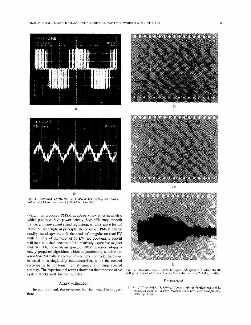
The drive system was tested on a laboratory test bed. The waveforms of the EAPWM line voltage and motor line current operating at 100 Hz are shown in Fig. 11. It can be found that the frequency ratio is selected as 12, which is a compromise between the switching loss and harmonic distortion. Fig. 12 shows the recorded motor speed, dc battery current, and motor line current. It can be observed that when steady state has been attained, the dc battery current and the motor line current are successively diminished to optimal values, while the motor speed is unchanged. Since the battery voltage is almost constant within the recording period, the input power is diminishing when delivering constant output power, leading to efficiency optimization of the inverter-motor set.
VII. CONCLUSION In this project, an advanced PMSM drive system for a
battery-powered mini-EV is presented. The design process of the PMSM adopts the electromagnetic approach, which can provide knowledge of critical areas and a tool for optimization, while the mathematical modeling of the PMSM employs a classical circuit approach, which is convenient to design the control strategy. With the employment of computer-aided
CHAN AND CHAU: PERMANENT MAGNET MOTOR DRIVE FOR BATTERY-POWERED ELECTRIC VEHICLES
~
187
(b)
Fig. 11. ms/div). (b) Motor line current (100 Ndiv, 5 ms/div).
Measured waveforms. (a) EAPWM line voltage (20 V/div, 2
design, the proposed PMSM adopting a new rotor geometry, which possesses high power density, high efficiency, smooth torque, and convenient speed regulation, is tailor-made for the mini-EV. Although, in principle, the proposed PMSM can be readily scaled upward to fit the needs of a regular on-road EV with a motor of the order of 50 kW, the economical benefit will be diminished because of the relatively expensive magnet material. The power-transistorized PWM inverter adopts a newly proposed algorithm, which is particularly suitable for a nonconstant battery voltage source. The controller hardware is based on a single-chip microcontroller, while the control software is to implement an efficiency-optimizing control strategy. The experimental results show that the proposed drive system works well for the mini-EV.
ACKNOWLEDGMENT The authors thank the reviewers for their valuable sugges-
(c)
Fig. 12. battery current (5 A/div, 6 s/div). (c) Motor line current (25 A/div, 6 ddiv).
Recorded results. (a) Motor speed (500 rpddiv, 6 s/div). (b) DC
REFERENCES
[ l ] C. C. Chani and C. S. Chang, “Electric vehicle development and its impact on utilities,’’ in Proc. Internat. Con$ Elec. Power Supply Ind.,
tions. 1986, pp. 1-24

188 IEEE TRANSACTIONS ON VEHICULAR TECHNOLOGY, VOL. 45, NO. 1, FEBRUARY 1996
[2] B. Bates and P. B. Patil, “ETXII-A second generation advanced ax. propulsion system,” in Proc. Internat. Elec. Veh. Symp., 1986, pp. 396405.
[3] C. C. Chan, W. S. Leung, and B. W. Williams, “An a.c. drive system for electric vehicles,” in Proc. Internat. Con$ Elec. Machines, 1984, pp. 83 1-834.
[4] C. C. Chan, “Electric road vehicles,” J. Hong Kong Eng., vol. 12, no. 12, pp. 13-22, Dec. 1984.
[5] C. C. Chan and K. T. Chau, “Advanced a.c. propulsion systems for electric vehicles,” in Proc. Internat. Symp. Automotive Tech. Automat., 1991, pp. 119-125.
[6] C. C. Chan and W. C. Lo, “Control strategy of PWM inverter drive system for electric vehicles,” IEEE Trans. Ind. Electron., vol. IE-34, no. 4, pp. 447456, Nov. 1987.
[7] C. C. Chan, W. S. Leung, and C. W. Ng, “Adaptive decoupling control of induction motor drives,” IEEE Trans. Ind. Electron., vol. E-37, no. 1, pp. 4147, Feb. 1990.
[8] K. J. Binns and T. M. Wong, “Analysis and performance of a high-field permanent-magnet synchronous machine,” IEE Proc., vol. 131, pt. B, no. 6, DP. 252-257, Nov. 1984.
191 E. Ri&er, T. J. E. Miller, T. W. Neumann, and T. L. Hudson, “The ferrite permanent magnet a.c. motor-A technical and economical assessment,” IEEE Trans. Ind. Applicat., vol. IA-21, no. 3, pp. 644-650, May/June 1985. M. Lajoie-Mazenc, C. Villanueva and J. Hector, “Study’ and imple- mentation of a hysteresis controlled inverter on a permanent magnet synchronous machine,” IEEE Tran. Ind. Applicat., vol. IA-21, no. 2, pp. 408413, Mar./Apr. 1985. P. Pillay and R. Krishnan, “Modeling of permanent magnet motor drives,” IEEE Trans. Ind. Electron., vol. E-35, no. 4, pp. 537-541, Nov. 1988. T. J. E. Miller, Brushless Permanent-Magnet and Reluctance Motor Drives. Oxford Universitv Press. 1989.
[13] D. Li, H. F. M i l d ” and K. J. Stmat, “Permanent magnet properties of sintered Nd-Fe-B between -40 and +2OO0C,” J. Appl. Phys., vol. 57, no. 1, pp. 4140-4142, Apr. 1985.
[14] M. A. Rahman and G. R. Selmon, “Promising applications of neodymium boron iron magnets in electrical machines,” IEEE Tram. Magnet., vol. MAG-21, no. 5, pp. 1712-1716, Sept. 1985.
[15] S. A. Nasar and G. Xiong, “Determination of the field of a permanent- magnet disk machine using the concept of magnetic charge,” IEEE Trans. Magnet., vol. MAG-24, no. 3, pp. 2038-2044, May 1988.
[16] S. J. Salon, “Finite element analysis of electric machinery,” IEEE Comput. Applicat. Power, vol. 3, no. 2, pp. 29-32, Apr. 1990.
[17] C. C. Chan and K. T. Chau, “Computer graphics aided design for an advanced electrical motor,” Comput. Aided Eng. J. , vol. 7, no. 3, pp. 72-74, June 1990.
[18] -, “Design of electrical machines by the finite element method using distributed computing,” J. Computers in Industry, vol. 17, no. 4, pp. 367-374, Dec. 1991.
[I91 R. S. Colby and D. W. Novotny, “Efficient operation of surface-mounted PM synchronous motors,” IEEE Trans. Ind. Applicat., vol. IA-23, no. 6, pp. 1048-1054, Nov./Dec. 1987.
[20] __ , “An efficiency-optimizing permanent-magnet synchronous mo- tor drive,” IEEE Trans. Ind. Applicat., vol. IA-24, no. 3, pp. 452469, May/June 1988.
[2!] C. C. Chan and K. T. Chau, “A new PWM algorithm for battery-source three-phase inverter,” J. Electric Machines & Power Systems, vol. 19, no. 1, pp. 43-54, Jan./Feb. 1991.
I
[22] P. Silvester and M. V K. Chari, “Finite element solution of saturable magnetic field problems,” IEEE Trans Power Apparat Syst , vol. PAS- 89, no. 7, pp. 1642-1651, Sept/Oct 1970.
[23] H Weh, H. Mosebach, and H. May, “Design concepts and force generaaon in inverter-fed synchronous machines with permanent magnet excitation,” IEEE Trans Magnet., vol. MAG-20, no. 5, pp 1756-1761, Sept. 1984.
[24] The Personal IRIS-Technical Report, Silicon Graphics, 1989. [25] D. Y. Chen, “Power semconductors Fast, tough, and compact,” IEEE
Spectrum, pp. 3G35, Sept 1987. [26] Semzconductor Power Module, Mitsubishi, 1989. [27] Power MOSFET & GTR Module, Toshiba, 1989. [28] C. C Chan and K. T. Chau, “A novel PWM algorithm for single-
chip microcomputer-based three-phase inverter,’’ in Proc Internat Conf Power Electron. & Motion Cont., 1990, pp 445449
[29] Embedded Controller Handbook, vol. 11, Intel, 1989.
of Odessy. He holds mc
C. C. Chan started his professional electrical en- gineenng career in 1959. He has been working 11 years in industry and 24 years in academc mstitu- tions. He is now the endowed Honda Professor and head of the Department of Electrical & Electronic Engineenng at the University of Hong Kong. He is also the Director of the International Research Center for Electric Vehicles. He was a Visiting Pro- fessor at several well-known universitles, including the University of Califomia at Berkeley, and was awarded the Hon.D.Sc degree from the University
Ire than 20 posts on international c o m t t e e s and serves as consultant to several organizations in Hong Kong and the U S He is the co-founder of the World Electric Vehicle Association and is known as one of the three wise men in the intemational electric vehicle community. He has published four books and more than 100 papers on electrical engineering.
Dr. Chan is a Fellow of IEE and HUE, Chairman of an IEEE technical committee, and is listed in Intemational Leaders of Achievement, Men of Achievement, Who’s Who in Australasia and the Far East.
include advanced m has published more reports.
otor than
K. T. Chau received first-class honors B Sc (Eng ), M Phil., and Ph D. degrees in electrical and elec- tromc engineering from the University of Hong Kong in 1988, 1991, and 1993, respectively He re- ceived the Sir Edward Youde Memonal Fellowships for the years 1988-89 and 1989-90
From 1990 to 1994, he worked as Lecturer in the Department of Elecmcal Engineering at Hong Kong Polytechnic University Since 1995 he has been with the Department of Electncal & Electronic Engmeer- ing, Umversity of Hong Kong His research interests dnves, electnc vehicles, and power electronics. He 40 refereed technical papers and several indnstnal