Embed Size (px)
Citation preview
An Energy-Driven Motion Planning Methodfor Two Distant Postures
HeWang, Edmond S.L. Ho, and Taku Komura
Abstract—In this paper, we present a local motion planning algorithm for character animation. We focus on motion planning between
two distant postures where linear interpolation leads to penetrations. Our framework has two stages. The motion planning problem is
first solved as a Boundary Value Problem (BVP) on an energy graph which encodes penetrations, motion smoothness and user control.
Having established a mapping from the configuration space to the energy graph, a fast and robust local motion planning algorithm is
introduced to solve the BVP to generate motions that could only previously be computed by global planning methods. In the second
stage, a projection of the solution motion onto a constraint manifold is proposed for more user control. Our method can be integrated
into current keyframing techniques. It also has potential applications in motion planning problems in robotics.
Index Terms—Character animation, motion planning
Ç
1 INTRODUCTION
SYNTHESIZING movements that involve close interactions,such as those in wrestling, dancing, carrying objects,
and passing through constrained environments, is essentialfor applications such as computer animations, computergames, and robotics. Collisions and contacts between indi-vidual body parts and the body with objects in the environ-ment are very common, which makes the path planningproblem extremely difficult to solve.
One common practice in computer animation for synthe-sizing such movements is keyframing. Key postures areinserted manually between frames so that every two conse-cutive postures can be smoothly interpolated. If we see thegenerated motion as a function, this method finds themotion function passing through the initial and end posturein the configuration space. This assumes every two consecu-tive postures are close enough so that the motion functioncan be approximated well by a piece-wise linear function.However, due to the representation of postures based onjoint angles, which does not take into account the spatialrelationships between different body parts or the body andobjects in the environment, many key frames are requiredto produce a penetration free, natural motion. As a result,only very experienced animators can produce a realisticmotion that involves such close interactions.
Alternatively, global motion planning approaches suchas Rapidly-exploring Random Trees (RRT) [1] or Probabilis-tic Road Maps (PRM) [2] are possible solutions. These meth-ods explore the configuration space in a random fashion to
find possible solutions connecting postures. However, thecomputational expense is high due to the curse ofdimensionality [3]. In addition, they become slow whenthere are narrow passages in the configuration space, whichis usually the case when there are many body parts andobjects in close proximity.
In this paper, we propose a method to solve this problemby composing an energy graph where distances betweendifferent body parts are taken into account. Smooth motionsare calculated as geodesic lines between the start and endnodes on the energy graph. Based on this concept, we formthe motion planning problem between two arbitrary pos-tures of a human skeleton character as a Boundary ValueProblem (BVP).
Besides the boundary conditions, the formulation of theBVP needs to consider three factors: (1) Physical plausibility,for instance, there should be no penetrations. (2) Smoothness.(3) Incorporation of user control. First, we construct an energygraph that meets these requirements. Next, we develop aniterative algorithm to compute the geodesic line betweenthe two postures. Finally, we project the motion functiononto a constraint manifold incorporating factors such asphysical constraints and additional user control.
The structure of the remainder of this paper is as follows.We first review closely related work in computer animation,robotics and computational geometry in Section 2. Then wegive an overview of our method in Section 3, followed bydetailed explanations of the methodology in Sections 4, 5and 6. Then, experimental results are presented and evalu-ated in Section 7. Finally, limitations are discussed in Sec-tion 8 and the conclusion is drawn in Section 9.
2 RELATED WORK
Character animation has been an active field in the pasttwo decades. Although we are trying to target a classicproblem, we take a new perspective by modeling the pos-ture via interactions between different body parts. It nar-rows our review scope down to interaction simulation and
� H. Wang is with the School of Informatics, University of Edinburgh, Edin-burgh, Midlothian, United Kingdom. E-mail: [email protected].
� E.S.L. Ho is with the Department of Computer Science, Hong Kong Bap-tist University, Hong Kong. E-mail: [email protected].
� T. Komura is with the School of Informatics, University of Edinburgh,Edinburgh, Midlothian, United Kingdom. E-mail: [email protected].
Manuscript received 17 Aug. 2013; revised 2 May 2014; accepted 23 May2014. Date of publication 2 June 2014; date of current version 26 Nov. 2014.Recommended for acceptance by R. Boulic.For information on obtaining reprints of this article, please send e-mail to:[email protected], and reference the Digital Object Identifier below.Digital Object Identifier no. 10.1109/TVCG.2014.2327976
18 IEEE TRANSACTIONS ON VISUALIZATION AND COMPUTER GRAPHICS, VOL. 21, NO. 1, JANUARY 2015
1077-2626� 2014 IEEE. Personal use is permitted, but republication/redistribution requires IEEE permission.See http://www.ieee.org/publications_standards/publications/rights/index.html for more information.
path-planning for complex movements. We first reviewsome works of simulating close interactions for characteranimation. Then we move on to path-planning methodsfor synthesizing movements of close interactions. Finally,we review the work in computational geometry that han-dles similar problems.
2.1 Interaction in Animation
Character interactions have been attracting many research-ers. Liu et al. [4] simulate the close dense interactions of twocharacters by repetitively updating the motion of each char-acter with spacetime constraints. Lee and Lee [5] produce aboxing match by reinforcement learning. Treuille et al. [6]use reinforcement learning to simulate pedestrians avoidingeach other. Shum et al. [7] use interaction patches to synthe-size multi-character fighting. However, these interactionsdo not include movements, such as Yoga, where body partsare in proximity and penetrations cannot be avoided bysimple methods.
Kallmann et al. [8] propose a Probabilistic Roadmap-based planning algorithm to synthesize reaching and grasp-ing motion while assuming prior knowledge about themotion. Pan et al. [9] propose an efficient method to planthe motion in constrained environment by classifying bodyparts into groups with low-correlation. Their methodassumes that some body parts can always be de-correlated,which is not always the case in motions such as Yoga andContortion. Wang et al. [10], [11] suggest control methods tointeract with deformable objects. They deal with a highnumber of degrees of freedom but the character control istoo simple to handle impending penetrations.
Ho and Komura [12], [13] propose to use topologicalmeasures to encode complex interactions so that very closeand continuous interactions can be analyzed and synthe-sized. However, their methods mainly encode tanglinginformation which is only useful when tangles are present.
2.2 Path-Planning of Close Interactions
Early work in path planning [14] employs potential fields tocompute collision-free paths efficiently. Kuffner et al. [15]propose a fast distance determination method to detect self-collision of the body parts of humanoid robots using Voro-noi-clip algorithm. Sugiura et al. [16] propose a method toavoid self-collision for humanoid robots by adding virtualforces between the body segments to maintain the mini-mum distances while reaching the target configuration.
Global path-planning such as Rapidly-exploringRandom Trees [1] or Probabilistic Road Maps [2] are oftenused in both animation and robotics. Yamane et al. [17] sim-ulate motions to move luggage from one place to another bycombining IK and RRT. Hirano et al. [18] and Berensonet al. [19] propose to use RRT to search the state space forgrasping objects. Zhang et al. [20] propose an approach sim-ilar to [9] and blend the motion with MOCAP data to pro-duce realistic human motion. Ho and Komura [21] use RRTto plan motions such as holding and piggybacking. Laddand Kavraki [22] develop a variation of RRT to untangleknots. Their work is similar to ours in the way that they usean energy function to break the global path-planing prob-lem into local problems that are manageable. There are two
shortcomings for these methods: 1. They are usually compu-tationally expensive. In order to search for collision-freepaths, it requires sampling in a large space and evaluationfor various factors. 2. Because the final path is built uponrandom search, the motion style is not consistent. Besides,post-processing is usually needed to ensure the smoothness.Therefore, these approaches are not ideal from the view-point of character motion synthesis and editing.
The most similar work to ours is [23], which uses linkageunfolding to plan the motions. However, their method issolely based on linkage folding/unfolding. The user doesnot have enough control over the motion synthesis process.
2.3 Linkage Unfolding in Computational Geometry
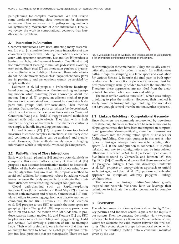
Since characters are commonly represented by tree-struc-ture skeletons, character motions can be seen as motions by3D polygonal trees, that have been investigated in computa-tional geometry. More specifically, a number of researchershave looked into the configuration space of linkages forfolding/unfolding. One main question in this area is whattypes of linkages always have connected configurationspaces [24]. If the configuration is connected, it is calledunlocked, and any two configurations can be interpolated.Otherwise it is called locked. In 3D, a locked open chain offive links is found by Cantarella and Johnson [25] (seeFig. 1). In [26], Connelly et al. prove that there are no locked2D polygonal linkages. Upon this discovery, Cantarellaet al. [27] propose an energy-driven approach to unfoldsuch linkages, and Iben et al. [28] propose an extendedapproach to interpolate arbitrary polygonal linkageconfigurations.
The research of linkage folding/unfolding greatlyinspired our research. We show how we leverage theirtechniques to facilitate the motion generation for complexpostures.
3 OVERVIEW
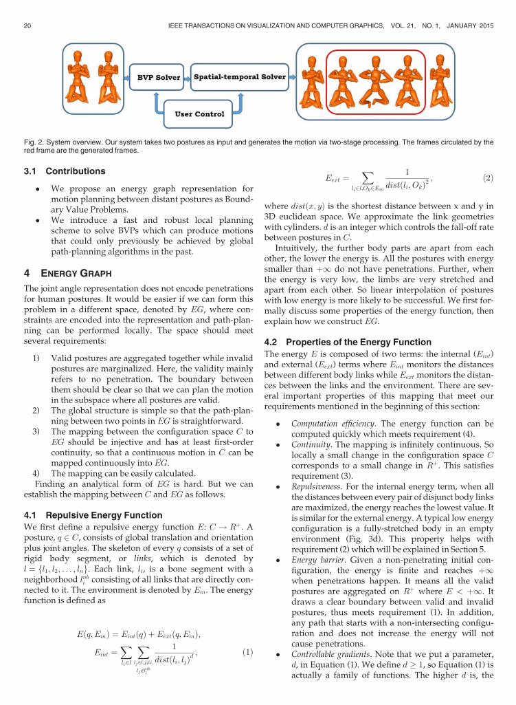
The whole framework of our system is shown in Fig. 2. Twokey postures and the user control signals are the inputs toour system. Then we generate the motion via a two-stageprocess. The first stage is a Boundary Value Problem solver,where we calculate the valid motion between the two pos-tures. The second stage is a spatial-temporal solver whichprojects the resulting motion onto a constraint manifoldgiven by the user.
Fig. 1. A locked linkage of five links. This linkage cannot be unfolded intoa flat one without penetrations or change of link lengths.
WANG ET AL.: AN ENERGY-DRIVEN MOTION PLANNING METHOD FOR TWO DISTANT POSTURES 19
3.1 Contributions
� We propose an energy graph representation formotion planning between distant postures as Bound-ary Value Problems.
� We introduce a fast and robust local planningscheme to solve BVPs which can produce motionsthat could only previously be achieved by globalpath-planning algorithms in the past.
4 ENERGY GRAPH
The joint angle representation does not encode penetrationsfor human postures. It would be easier if we can form thisproblem in a different space, denoted by EG, where con-straints are encoded into the representation and path-plan-ning can be performed locally. The space should meetseveral requirements:
1) Valid postures are aggregated together while invalidpostures are marginalized. Here, the validity mainlyrefers to no penetration. The boundary betweenthem should be clear so that we can plan the motionin the subspace where all postures are valid.
2) The global structure is simple so that the path-plan-ning between two points in EG is straightforward.
3) The mapping between the configuration space C toEG should be injective and has at least first-ordercontinuity, so that a continuous motion in C can bemapped continuously into EG.
4) The mapping can be easily calculated.Finding an analytical form of EG is hard. But we can
establish the mapping between C and EG as follows.
4.1 Repulsive Energy Function
We first define a repulsive energy function E: C ! Rþ. Aposture, q 2 C, consists of global translation and orientationplus joint angles. The skeleton of every q consists of a set ofrigid body segment, or links, which is denoted byl ¼ fl1; l2; . . . ; lng. Each link, li, is a bone segment with aneighborhood lnbi consisting of all links that are directly con-nected to it. The environment is denoted by Em. The energyfunction is defined as
Eðq; EmÞ ¼ EintðqÞ þ Eextðq; EmÞ;Eint ¼
Xli2l
Xlj2l;j 6¼i;lj 62lnbi
1
distðli; ljÞd; (1)
Eext ¼X
li2l;Ok2Em
1
distðli; OkÞ2; (2)
where distðx; yÞ is the shortest distance between x and y in3D euclidean space. We approximate the link geometrieswith cylinders. d is an integer which controls the fall-off ratebetween postures in C.
Intuitively, the further body parts are apart from eachother, the lower the energy is. All the postures with energysmaller than þ1 do not have penetrations. Further, whenthe energy is very low, the limbs are very stretched andapart from each other. So linear interpolation of postureswith low energy is more likely to be successful. We first for-mally discuss some properties of the energy function, thenexplain how we construct EG.
4.2 Properties of the Energy Function
The energy E is composed of two terms: the internal (Eint)and external (Eext) terms where Eint monitors the distancesbetween different body links while Eext monitors the distan-ces between the links and the environment. There are sev-eral important properties of this mapping that meet ourrequirements mentioned in the beginning of this section:
� Computation efficiency. The energy function can becomputed quickly which meets requirement (4).
� Continuity. The mapping is infinitely continuous. Solocally a small change in the configuration space Ccorresponds to a small change in Rþ. This satisfiesrequirement (3).
� Repulsiveness. For the internal energy term, when allthe distances between every pair of disjunct body linksare maximized, the energy reaches the lowest value. Itis similar for the external energy. A typical low energyconfiguration is a fully-stretched body in an emptyenvironment (Fig. 3d). This property helps withrequirement (2) whichwill be explained in Section 5.
� Energy barrier. Given a non-penetrating initial con-figuration, the energy is finite and reaches þ1when penetrations happen. It means all the validpostures are aggregated on Rþ where E < þ1. Itdraws a clear boundary between valid and invalidpostures, thus meets requirement (1). In addition,any path that starts with a non-intersecting configu-ration and does not increase the energy will notcause penetrations.
� Controllable gradients. Note that we put a parameter,d, in Equation (1). We define d � 1, so Equation (1) isactually a family of functions. The higher d is, the
Fig. 2. System overview. Our system takes two postures as input and generates the motion via two-stage processing. The frames circulated by thered frame are the generated frames.
20 IEEE TRANSACTIONS ON VISUALIZATION AND COMPUTER GRAPHICS, VOL. 21, NO. 1, JANUARY 2015
larger the energy fall-off rate is. Its function will beexplained in Section 5.
4.3 BVP and Energy Graph Construction
With these properties, we form a Boundary Value Problemfor motion generation. C is a high-dimensional vector field,Equation (1) assigns a scalar from Rþ to every vector in Cand gives us a new space EG. So we let EG ¼ C �Rþ.Given two postures P1, P2 2 C and their correspondingpoints EGðP1Þ, EGðP2Þ 2 EG, we look for a functionf : t! C, t 2 0; 1½ � bounded by fð0Þ ¼ P1 and fð1Þ ¼ P2.Directly solving such a BVP requires additional informa-tion about f , such as higher-order information similar tothe classic Dirichlet Problem. In our problem, we wouldlike to find a f so that the following energy is minimized:
EfðfðtÞÞ ¼Z 1
t¼0k E0ðfðtÞÞ k2 df
’X1t¼0k E0ðfðtÞÞ k2
subject to
fð0Þ ¼ P1 fð1Þ ¼ P2 and Ef < þ:
(3)
Such an f essentially corresponds to the geodesic pathbetween EGðP1Þ and EGðP2Þ in EG. However, Equation (1)is only injective, not diffeomorphic. So EG is not necessarilya manifold.
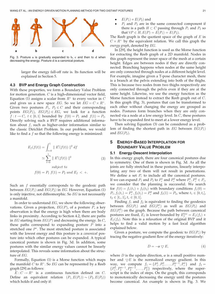
In order to understand EG, we show the following obser-vations. Given a projection, EGðP Þ, of a posture P , a keyobservation is that the energy is high when there are bodylinks in proximity. According to Section 4.2, there are pathsin EG starting from EGðP Þ and decreasing the energy. In C,these paths correspond to expanding posture P into astretched one Pe. The most stretched posture is associatedwith the lowest energy and this posture is a canonical pos-ture into which other postures can be expanded. A typicalcanonical posture is shown in Fig. 3d. In addition, somepostures with the similar energy values cannot be linearlyinterpolated. This reveals some information about the struc-ture of EG.
Formally, Equation (1) is a Morse function which mapsthe manifold C to Rþ. So EG can be represented by a Reebgraph [29] as follows:
E : C ! Rþ is a continuous function defined on C.Define an equivalent relation ðP1; EðP1ÞÞ � ðP2; EðP2ÞÞwhich holds if and only if:
� EðP1Þ = EðP2Þ and� P1 and P2 are in the same connected component if
there is a path H � C passing through P1 and P2 sothat 8P 2 H;EðP Þ ¼ EðP1Þ ¼ EðP2Þ.
The Reeb graph is the quotient space of the graph of E inC �Rþ by the equivalent relation. We call this graph theenergy graph, denoted by EG.
In [29], the height function is used as the Morse functionfor extracting the Reeb graph of a 2D manifold. Nodes inthis graph represent the inner space of the mesh at a certainheight. Edges are between nodes if they are directly con-nected. Branching happens when nodes at the same heightare only connected through nodes at a different height level.For example, imagine given a T-pose character mesh, thereis a branch at the pelvis extending into both of the thighs.This is because two nodes from two thighs respectively areonly connected through the pelvis even if they are at thesame height. Likewise, we use the energy function as theMorse function instead to extract the Reeb graph out of C.In this graph (Fig. 3), postures that can be transformed toeach other without changing the energy are grouped asnodes. Postures form branches when they are only con-nected via a node at a low energy level. In C, these postureshave to be expanded first to meet at a lower energy level.
Then solving Equation (3) can be considered as a prob-lem of finding the shortest path in EG between EGðP1Þand EGðP2Þ.
5 ENERGY-BASED INTERPOLATION FOR
BOUNDARY VALUE PROBLEM
5.1 Energy-Descent Interpolation
In this energy graph, there are four canonical postures dueto symmetry. One of them is shown in Fig. 3d. As all thejoints are fully stretched in these postures, linearly interpo-lating any two of them will not result in penetrations.We define a set Pc to include all the canonical postures.If we can expand P1 and P2 to P 1
c and P 2c where P 1
c ; P2c 2 Pc,
we consider that the planning is successful. We searchfor fðtÞ ¼ f1ðt1Þ þ f2ðt2Þ with boundary conditions f1ð0Þ ¼P1; f1ðtcÞ ¼ P 1
c ; f2ðtcÞ ¼ P 2c and f2ð1Þ ¼ P2, where t1 2 0; tc½ �,
t2 2 tc; 1½ �, tc 2 0; 1½ �.Finding f1 and f2 is equivalent to finding the geodesics
between EGðP1Þ and EGðP 1c Þ as well as EGðP2Þ and
EGðP 2c Þ on the graph. Because the path between canonical
postures are fixed, Ef is lower-bounded by Elowf ¼ Efðf1Þ +
Efðf2Þ. Note this is a relaxation of the original BVP and ithelps to find a valid motion by a fast local algorithmexplained below.
Given a posture, we compute the geodesic to EGðPcÞ bytracing the negative gradient flow of the energy iteratively:
D ¼ �a5 E; (4)
where D is the update direction, a is a small positive num-ber and 5E is the normalized energy gradient. In thisway, we compute f1 ¼ fP 1
1 ; P21 ; . . . ; P
n�11 ; P 1
c g and f2 ¼fP 2
c ; Pm�12 ; Pm�2
2 ; . . . ; P 12 g respectively, where the super-
script is the index of steps. On the graph, this correspondsto monotonically decreasing the energy until the posturesbecome canonical. An example is shown in Fig. 3. We
Fig. 3. Posture a is gradually expanded to b, c and then to d whendecreasing the energy. Posture d is a canonical posture.
WANG ET AL.: AN ENERGY-DRIVEN MOTION PLANNING METHOD FOR TWO DISTANT POSTURES 21
emphasize that Pc is not fully connected. Theoretically, itcan cause failure when two postures are expanded into twocanonical postures that are not connected. However, experi-mentally we find linear interpolation between canonicalpostures will not cause penetrations thus can be used. Moredetails are given in Section 5.2.2.
5.2 Relaxation by Linear Interpolation and SafeZone
5.2.1 Leveraging Linear Interpolation
Although the motion can be generated by energy-descentplanning as shown in Fig. 3, sometimes the synthesizedmovements include unnecessary expansion, which is differ-ent from natural motions that usually take the shortest path.This is because the energy of a canonical posture, EðPlowÞwhere Plow 2 Pc is too low and simply tracing the negativegradient flow is too strict. To address this problem, weemploy two strategies: using linear interpolation andincreasing the fall-off rate d in Equation (1).
Linear interpolation follows the shortest path in C thusshould be applied when the synthesized motion does notcause any penetrations. In each iteration, we check if it willcause penetrations. If it does not, we only use linear interpola-tion. Otherwise, we project the linear interpolation directionto the null space of the energy gradient so it does not increasethe energy. This requires to compute a safe zone which isexplained later aswell as amodification of Equation (4).
We employ the same strategy proposed in [28]. At everystep, instead of changing both postures, we update the pos-ture with the higher energy, Ph, towards the other posture,Pl. So D is first initialized by Pl�Ph
kPl�Phk, then Equation (4) ischanged into:
D ¼ aD if DT 5E 0;ðI �5E 5ET ÞD otherwise,
�(5)
where a is the same parameter as in Equation (4). Equa-tion (5) essentially projects the linear interpolation direction,Pl�PhkPl�Phk, so that it does not increase the energy. In this way,unnecessary expansions can be mitigated.
Incorporating linear interpolation into the energy-descentapproach results in actively finding a common posture P 0lowsuch that EðP 0lowÞ > EðPlowÞ. In the energy graph, EGðP 0lowÞ
is a common parent node that is closer toEGðP1Þ andEGðP2Þthan EGðPcÞ, thus reduces the total distance that the twobodies have to travel on the graph to meet each other. Thehigher EðP 0lowÞ is, the less the two bodies have to travel, thusdecreaseEf . An illustrative example is shown in Fig. 4.
Although using a posture with a lower energy as a waypoint can reduce excessive expansion of the bodies, someunnecessary expansion still happens especially at theperipheral joints. This is because the energy function tracesthe energy between all pairs of body links and expandsall parts almost equally. To tackle this issue, we tunethe energy fall-off rate between postures by adjusting d inEquation (1). A high value makes the energy more domi-nated by the closest pair of body links, therefore they areexpanded more. The user can change the style of the motionby adjusting the value of d. Experimental results of synthe-sized motions with different ds are shown in Section 7.2.
5.2.2 Safe Zone
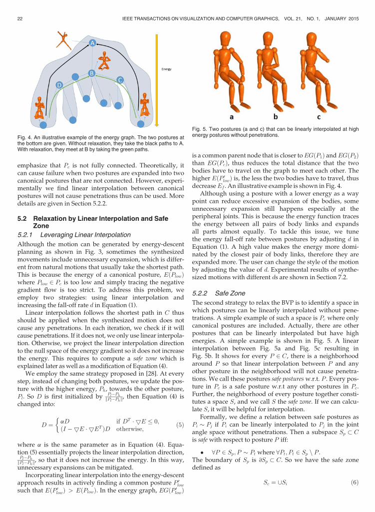
The second strategy to relax the BVP is to identify a space inwhich postures can be linearly interpolated without pene-trations. A simple example of such a space is Pc where onlycanonical postures are included. Actually, there are otherpostures that can be linearly interpolated but have highenergies. A simple example is shown in Fig. 5. A linearinterpolation between Fig. 5a and Fig. 5c resulting inFig. 5b. It shows for every P 2 C, there is a neighborhoodaround P so that linear interpolation between P and anyother posture in the neighborhood will not cause penetra-tions. We call these postures safe posturesw.r.t. P . Every pos-ture in Pc is a safe posture w.r.t any other postures in Pc.Further, the neighborhood of every posture together consti-tutes a space S, and we call S the safe zone. If we can calcu-late S, it will be helpful for interpolation.
Formally, we define a relation between safe postures asPi � Pj if Pi can be linearly interpolated to Pj in the jointangle space without penetrations. Then a subspace Sp � Cis safewith respect to posture P iff:
� 8P 2 Sp; P � Pt where 8Pt; Pt 2 Sp n P .The boundary of Sp is @Sp � C. So we have the safe zonedefined as
Sc ¼ [Si (6)
Fig. 4. An illustrative example of the energy graph. The two postures atthe bottom are given. Without relaxation, they take the black paths to A.With relaxation, they meet at B by taking the green paths.
Fig. 5. Two postures (a and c) that can be linearly interpolated at highenergy postures without penetrations.
22 IEEE TRANSACTIONS ON VISUALIZATION AND COMPUTER GRAPHICS, VOL. 21, NO. 1, JANUARY 2015
with its boundary @Sc ¼ [@Si. Intuitively, there is a sub-space of Sp in C around every posture P. For example, Pa, Pb
and Pc in Fig. 5 are in Sa \ Sb \ Sc so any two of them can belinearly interpolated. Note the relation is reflective, symmet-ric but not transitive. So only postures within the same sub-space of S can be linearly interpolated. Fig. 2 shows tworepresentative postures. In the output, every two consecu-tive postures are in the same subspace, but clearly the firstand last posture are not.
Safe zone allows us to further shorten the motion path.Previously, linear interpolation is only applied when it doesnot increase the energy. Introducing S changes the BVP inthe following way. Given two postures P1 and P2, they canbe expanded into Pe
1 and Pe2 where Pe
1 ; Pe2 2 @Si. Here Si can
be Pc or any other subspace of Sc. The worst case is whenSi ¼ Pc which means P1 and P2 are fully expanded. How-ever, this can happen way before they meet each other bythe method explained in the last section. When it happens,linear interpolation between Pe
1 and Pe2 further shortens the
path. The solution thus is changed to: f1 ¼ fP 11 ; P 2
1 ; . . . ;Pn�11 ; P e
1g, f2 ¼ fPe2 ; P
m�12 ; Pm�2
2 ; . . . ; P e2g and f ¼ f1þ
LinearInterpolationðPe1 ; P
e2 Þ þ f2.
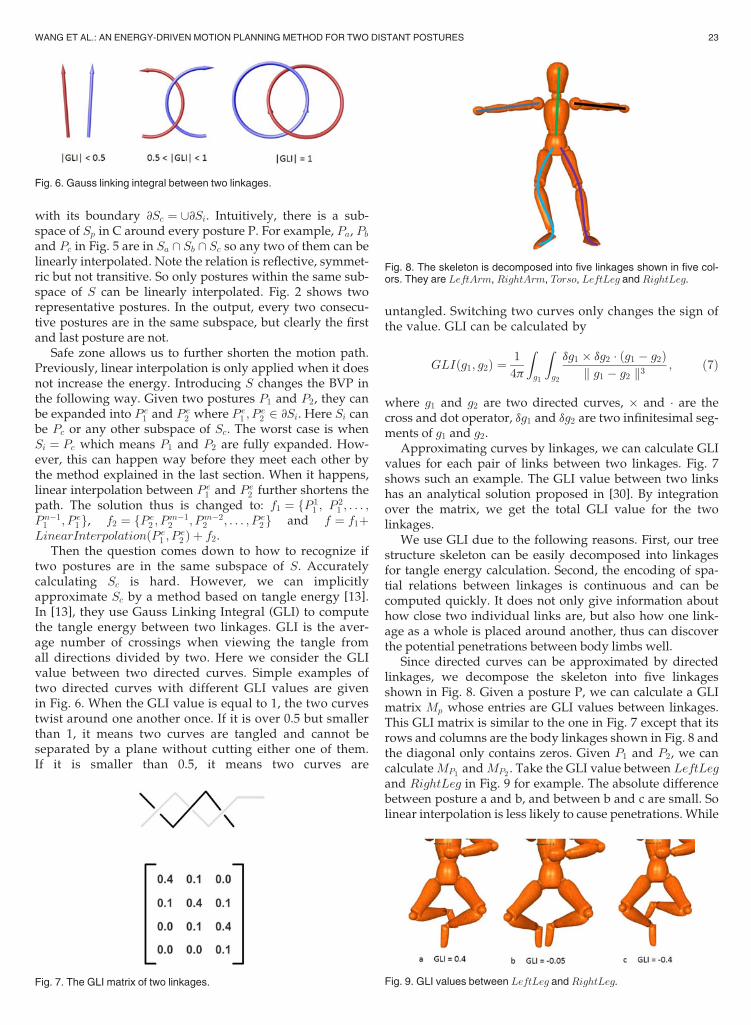
Then the question comes down to how to recognize iftwo postures are in the same subspace of S. Accuratelycalculating Sc is hard. However, we can implicitlyapproximate Sc by a method based on tangle energy [13].In [13], they use Gauss Linking Integral (GLI) to computethe tangle energy between two linkages. GLI is the aver-age number of crossings when viewing the tangle fromall directions divided by two. Here we consider the GLIvalue between two directed curves. Simple examples oftwo directed curves with different GLI values are givenin Fig. 6. When the GLI value is equal to 1, the two curvestwist around one another once. If it is over 0.5 but smallerthan 1, it means two curves are tangled and cannot beseparated by a plane without cutting either one of them.If it is smaller than 0.5, it means two curves are
untangled. Switching two curves only changes the sign ofthe value. GLI can be calculated by
GLIðg1; g2Þ ¼ 1
4p
Zg1
Zg2
dg1 � dg2 ðg1 � g2Þk g1 � g2 k3 ; (7)
where g1 and g2 are two directed curves, � and are thecross and dot operator, dg1 and dg2 are two infinitesimal seg-ments of g1 and g2.
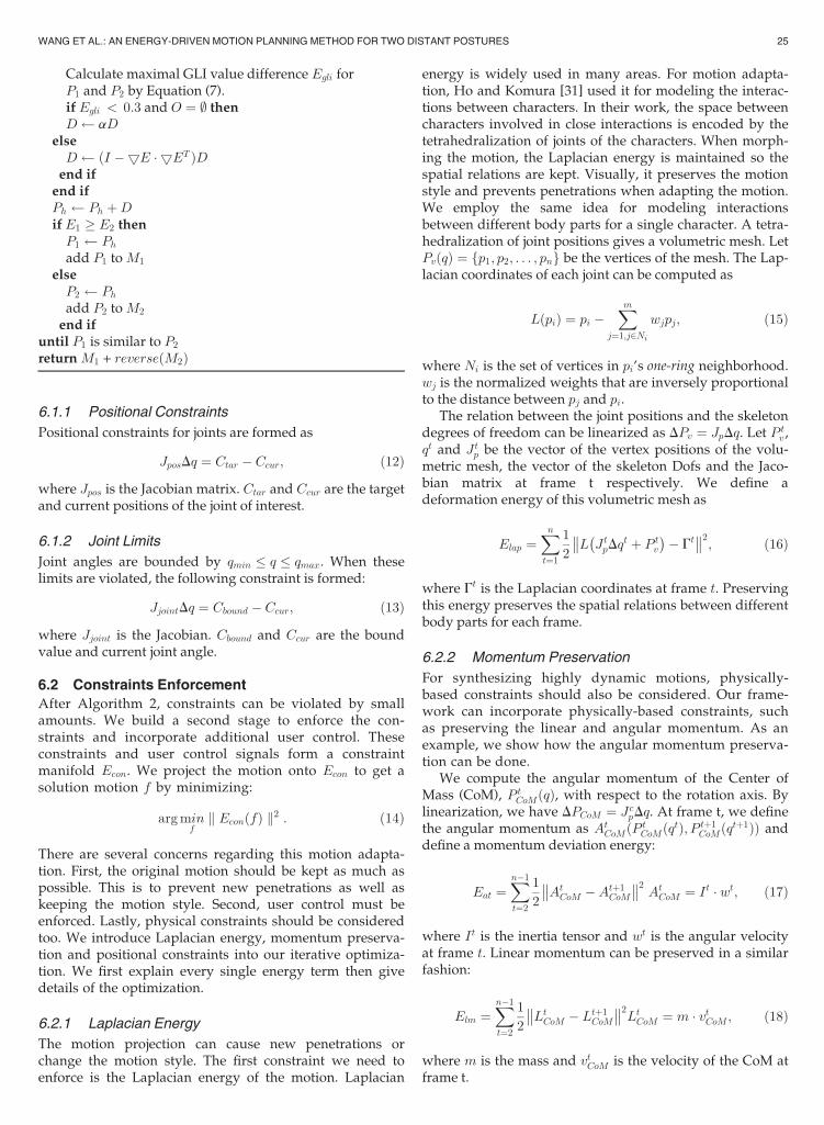
Approximating curves by linkages, we can calculate GLIvalues for each pair of links between two linkages. Fig. 7shows such an example. The GLI value between two linkshas an analytical solution proposed in [30]. By integrationover the matrix, we get the total GLI value for the twolinkages.
We use GLI due to the following reasons. First, our treestructure skeleton can be easily decomposed into linkagesfor tangle energy calculation. Second, the encoding of spa-tial relations between linkages is continuous and can becomputed quickly. It does not only give information abouthow close two individual links are, but also how one link-age as a whole is placed around another, thus can discoverthe potential penetrations between body limbs well.
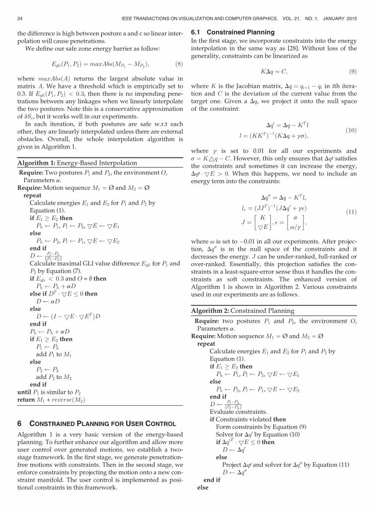
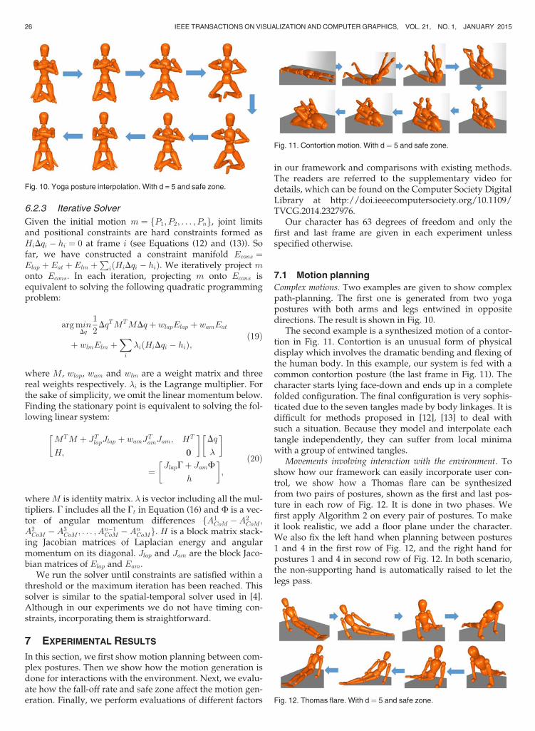
Since directed curves can be approximated by directedlinkages, we decompose the skeleton into five linkagesshown in Fig. 8. Given a posture P, we can calculate a GLImatrix Mp whose entries are GLI values between linkages.This GLI matrix is similar to the one in Fig. 7 except that itsrows and columns are the body linkages shown in Fig. 8 andthe diagonal only contains zeros. Given P1 and P2, we cancalculateMP1 andMP2 . Take the GLI value between LeftLegand RightLeg in Fig. 9 for example. The absolute differencebetween posture a and b, and between b and c are small. Solinear interpolation is less likely to cause penetrations. While
Fig. 6. Gauss linking integral between two linkages.
Fig. 7. The GLI matrix of two linkages.
Fig. 8. The skeleton is decomposed into five linkages shown in five col-ors. They are LeftArm, RightArm, Torso, LeftLeg and RightLeg.
Fig. 9. GLI values between LeftLeg and RightLeg.
WANG ET AL.: AN ENERGY-DRIVEN MOTION PLANNING METHOD FOR TWO DISTANT POSTURES 23
the difference is high between posture a and c so linear inter-polationwill cause penetrations.
We define our safe zone energy barrier as follow:
EgliðP1; P2Þ ¼ maxAbsðMP1 �MP2Þ; (8)
where maxAbsðAÞ returns the largest absolute value inmatrix A. We have a threshold which is empirically set to0.3. If EgliðP1; P2Þ < 0:3, then there is no impending pene-trations between any linkages when we linearly interpolatethe two postures. Note this is a conservative approximationof @Sc, but it works well in our experiments.
In each iteration, if both postures are safe w.r.t eachother, they are linearly interpolated unless there are externalobstacles. Overall, the whole interpolation algorithm isgiven in Algorithm 1.
Algorithm 1: Energy-Based Interpolation
Require: Two postures P1 and P2, the environment O,Parameters a.
Require:Motion sequenceM1 ¼ Ø andM2 ¼ Ørepeat
Calculate energies E1 and E2 for P1 and P2 byEquation (1).if E1 � E2 then
Ph P1, Pl P2,5E 5E1
elsePh P2, Pl P1,5E 5E2
end ifD Pl�Ph
kPl�PhkCalculate maximal GLI value difference Egli for P1 andP2 by Equation (7).if Egli < 0:3 and O = ; then
Ph Ph þ aDelse ifDT 5E 0 then
D aDelse
D ðI �5E 5ET ÞDend ifPh Ph þ aDif E1 � E2 then
P1 Ph
add P1 toM1
elseP2 Ph
add P2 toM2
end ifuntil P1 is similar to P2
returnM1 + reverseðM2Þ
6 CONSTRAINED PLANNING FOR USER CONTROL
Algorithm 1 is a very basic version of the energy-basedplanning. To further enhance our algorithm and allow moreuser control over generated motions, we establish a two-stage framework. In the first stage, we generate penetration-free motions with constraints. Then in the second stage, weenforce constraints by projecting the motion onto a new con-straint manifold. The user control is implemented as posi-tional constraints in this framework.
6.1 Constrained Planning
In the first stage, we incorporate constraints into the energyinterpolation in the same way as [28]. Without loss of thegenerality, constraints can be linearized as
KDq ¼ C; (9)
where K is the Jacobian matrix, Dq ¼ qiþ1 � qi in ith itera-tion and C is the deviation of the current value from thetarget one. Given a Dq, we project it onto the null spaceof the constraint:
Dq0 ¼ Dq �KTl
l ¼ ðKKT Þ�1ðKDq þ gsÞ;(10)
where g is set to 0.01 for all our experiments ands ¼ K~q � C. However, this only ensures that Dq0 satisfiesthe constraints and sometimes it can increase the energy,Dq0 5E > 0. When this happens, we need to include anenergy term into the constraints:
Dq00 ¼ Dq �KTle
le ¼ ðJJT Þ�1ðJDq0 þ g�Þ
J ¼ K
5E
� �; � ¼ s
v=g
� �;
(11)
where v is set to �0.01 in all our experiments. After projec-tion, Dq00 is in the null space of the constraints and itdecreases the energy. J can be under-ranked, full-ranked orover-ranked. Essentially, this projection satisfies the con-straints in a least-square-error sense thus it handles the con-straints as soft constraints. The enhanced version ofAlgorithm 1 is shown in Algorithm 2. Various constraintsused in our experiments are as follows.
Algorithm 2: Constrained Planning
Require: two postures P1 and P2, the environment O,Parameters a.
Require:Motion sequenceM1 ¼ Ø andM2 ¼ Ørepeat
Calculate energies E1 and E2 for P1 and P2 byEquation (1).if E1 � E2 then
Ph P1, Pl P2,5E 5E1
elsePh P2, Pl P1,5E 5E2
end ifD Pl�Ph
kPl�PhkEvaluate constraints.if Constraints violated then
Form constraints by Equation (9)Solver for Dq0 by Equation (10)if Dq0T 5E 0 then
D Dq0
elseProject Dq0 and solver for Dq00 by Equation (11)D Dq00
end ifelse
24 IEEE TRANSACTIONS ON VISUALIZATION AND COMPUTER GRAPHICS, VOL. 21, NO. 1, JANUARY 2015
Calculate maximal GLI value difference Egli forP1 and P2 by Equation (7).if Egli < 0:3 and O ¼ ; thenD aD
elseD ðI �5E 5ET ÞDend if
end ifPh Ph þDif E1 � E2 then
P1 Ph
add P1 toM1
elseP2 Ph
add P2 toM2
end ifuntil P1 is similar to P2
returnM1 + reverseðM2Þ
6.1.1 Positional Constraints
Positional constraints for joints are formed as
JposDq ¼ Ctar � Ccur; (12)
where Jpos is the Jacobian matrix. Ctar and Ccur are the targetand current positions of the joint of interest.
6.1.2 Joint Limits
Joint angles are bounded by qmin q qmax. When theselimits are violated, the following constraint is formed:
JjointDq ¼ Cbound � Ccur; (13)
where Jjoint is the Jacobian. Cbound and Ccur are the boundvalue and current joint angle.
6.2 Constraints Enforcement
After Algorithm 2, constraints can be violated by smallamounts. We build a second stage to enforce the con-straints and incorporate additional user control. Theseconstraints and user control signals form a constraintmanifold Econ. We project the motion onto Econ to get asolution motion f by minimizing:
argminfk EconðfÞ k2 : (14)
There are several concerns regarding this motion adapta-tion. First, the original motion should be kept as much aspossible. This is to prevent new penetrations as well askeeping the motion style. Second, user control must beenforced. Lastly, physical constraints should be consideredtoo. We introduce Laplacian energy, momentum preserva-tion and positional constraints into our iterative optimiza-tion. We first explain every single energy term then givedetails of the optimization.
6.2.1 Laplacian Energy
The motion projection can cause new penetrations orchange the motion style. The first constraint we need toenforce is the Laplacian energy of the motion. Laplacian
energy is widely used in many areas. For motion adapta-tion, Ho and Komura [31] used it for modeling the interac-tions between characters. In their work, the space betweencharacters involved in close interactions is encoded by thetetrahedralization of joints of the characters. When morph-ing the motion, the Laplacian energy is maintained so thespatial relations are kept. Visually, it preserves the motionstyle and prevents penetrations when adapting the motion.We employ the same idea for modeling interactionsbetween different body parts for a single character. A tetra-hedralization of joint positions gives a volumetric mesh. LetPvðqÞ ¼ fp1; p2; . . . ; png be the vertices of the mesh. The Lap-lacian coordinates of each joint can be computed as
LðpiÞ ¼ pi �Xm
j¼1;j2Ni
wjpj; (15)
where Ni is the set of vertices in pi’s one-ring neighborhood.wj is the normalized weights that are inversely proportionalto the distance between pj and pi.
The relation between the joint positions and the skeletondegrees of freedom can be linearized as DPv ¼ JpDq. Let P
tv ,
qt and Jtp be the vector of the vertex positions of the volu-
metric mesh, the vector of the skeleton Dofs and the Jaco-bian matrix at frame t respectively. We define adeformation energy of this volumetric mesh as
Elap ¼Xnt¼1
1
2
��L�JtpDq
t þ Ptv
�� Gt��2; (16)
where Gt is the Laplacian coordinates at frame t. Preservingthis energy preserves the spatial relations between differentbody parts for each frame.
6.2.2 Momentum Preservation
For synthesizing highly dynamic motions, physically-based constraints should also be considered. Our frame-work can incorporate physically-based constraints, suchas preserving the linear and angular momentum. As anexample, we show how the angular momentum preserva-tion can be done.
We compute the angular momentum of the Center ofMass (CoM), Pt
CoMðqÞ, with respect to the rotation axis. Bylinearization, we have DPCoM ¼ Jc
pDq. At frame t, we definethe angular momentum as At
CoMðPtCoMðqtÞ; P tþ1
CoMðqtþ1ÞÞ anddefine a momentum deviation energy:
Eat ¼Xn�1t¼2
1
2
��AtCoM �Atþ1
CoM
��2 AtCoM ¼ It wt; (17)
where It is the inertia tensor and wt is the angular velocityat frame t. Linear momentum can be preserved in a similarfashion:
Elm ¼Xn�1t¼2
1
2
��LtCoM � Ltþ1
CoM
��2LtCoM ¼ m vtCoM; (18)
where m is the mass and vtCoM is the velocity of the CoM atframe t.
WANG ET AL.: AN ENERGY-DRIVEN MOTION PLANNING METHOD FOR TWO DISTANT POSTURES 25
6.2.3 Iterative Solver
Given the initial motion m ¼ fP1; P2; . . . ; Png, joint limitsand positional constraints are hard constraints formed asHiDqi � hi ¼ 0 at frame i (see Equations (12) and (13)). Sofar, we have constructed a constraint manifold Econs ¼Elap þ Eat þElm þ
PiðHiDqi � hiÞ. We iteratively project m
onto Econs. In each iteration, projecting m onto Econs isequivalent to solving the following quadratic programmingproblem:
argminDq
1
2DqTMTMDq þ wlapElap þ wamEat
þ wlmElm þXi
�iðHiDqi � hiÞ;(19)
where M, wlap, wam and wlm are a weight matrix and threereal weights respectively. �i is the Lagrange multiplier. Forthe sake of simplicity, we omit the linear momentum below.Finding the stationary point is equivalent to solving the fol-lowing linear system:
MTM þ JTlapJlap þ wamJ
TamJam; HT
H; 0
� �Dq
�
� �
¼ JlapGþ JamF
h
� �;
(20)
whereM is identity matrix. � is vector including all the mul-tipliers. G includes all the Gt in Equation (16) and F is a vec-tor of angular momentum differences fA1
CoM �A2CoM;
A2CoM �A3
CoM; . . . ; An�1CoM �An
CoMg. H is a block matrix stack-ing Jacobian matrices of Laplacian energy and angularmomentum on its diagonal. Jlap and Jam are the block Jaco-bian matrices of Elap and Eam.
We run the solver until constraints are satisfied within athreshold or the maximum iteration has been reached. Thissolver is similar to the spatial-temporal solver used in [4].Although in our experiments we do not have timing con-straints, incorporating them is straightforward.
7 EXPERIMENTAL RESULTS
In this section, we first showmotion planning between com-plex postures. Then we show how the motion generation isdone for interactions with the environment. Next, we evalu-ate how the fall-off rate and safe zone affect the motion gen-eration. Finally, we perform evaluations of different factors
in our framework and comparisons with existing methods.The readers are referred to the supplementary video fordetails, which can be found on the Computer Society DigitalLibrary at http://doi.ieeecomputersociety.org/10.1109/TVCG.2014.2327976.
Our character has 63 degrees of freedom and only thefirst and last frame are given in each experiment unlessspecified otherwise.
7.1 Motion planning
Complex motions. Two examples are given to show complexpath-planning. The first one is generated from two yogapostures with both arms and legs entwined in oppositedirections. The result is shown in Fig. 10.
The second example is a synthesized motion of a contor-tion in Fig. 11. Contortion is an unusual form of physicaldisplay which involves the dramatic bending and flexing ofthe human body. In this example, our system is fed with acommon contortion posture (the last frame in Fig. 11). Thecharacter starts lying face-down and ends up in a completefolded configuration. The final configuration is very sophis-ticated due to the seven tangles made by body linkages. It isdifficult for methods proposed in [12], [13] to deal withsuch a situation. Because they model and interpolate eachtangle independently, they can suffer from local minimawith a group of entwined tangles.
Movements involving interaction with the environment. Toshow how our framework can easily incorporate user con-trol, we show how a Thomas flare can be synthesizedfrom two pairs of postures, shown as the first and last pos-ture in each row of Fig. 12. It is done in two phases. Wefirst apply Algorithm 2 on every pair of postures. To makeit look realistic, we add a floor plane under the character.We also fix the left hand when planning between postures1 and 4 in the first row of Fig. 12, and the right hand forpostures 1 and 4 in second row of Fig. 12. In both scenario,the non-supporting hand is automatically raised to let thelegs pass.
Fig. 10. Yoga posture interpolation. With d = 5 and safe zone.
Fig. 11. Contortion motion. With d ¼ 5 and safe zone.
Fig. 12. Thomas flare. With d ¼ 5 and safe zone.
26 IEEE TRANSACTIONS ON VISUALIZATION AND COMPUTER GRAPHICS, VOL. 21, NO. 1, JANUARY 2015
In the second phase of motion synthesis, we enforce Lap-lacian energy and angular momentum constraints as well aspositional constraints for hands then optimize the motionby Equation (19). Since the last postures of the two motionsare the same, the two motions can be easily concatenatedinto a whole motion.
7.2 Evaluations and Comparisons
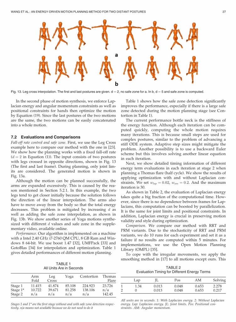
Fall-off rate control and safe zone. First, we use the Leg Crossexample here to compare our method with the one in [23].We show how the planning works with a fixed fall-off rate(d ¼ 2 in Equation (1)). The input consists of two postureswith legs crossed in opposite directions, shown in Fig. 13(The first and last frame). During planning, only joint lim-its are considered. The generated motion is shown inFig. 13a.
Although the motion can be planned successfully, thearms are expanded excessively. This is caused by the rea-son mentioned in Section 5.2.1. In this example, the twolegs tend to get closer initially because the solution followsthe direction of the linear interpolation. The arms alsohave to move away from the body so that the total energydecreases. This problem is mitigated by increasing d aswell as adding the safe zone interpolation, as shown inFig. 13b. We show another series of Yoga motions synthe-sized with different d values and safe zone in the supple-mentary video, available online.
Performance. Our algorithm is implemented on a machinewith a Intel 2.40 GHz i7-2760 QM CPU, 8 GB Ram and Win-dows 8 64-bit. We use boost 1.47 [32], UMFPack [33] andGotoBlas [34] for interpolation and optimization. Table 1gives detailed performances of different motion planning.
Table 1 shows how the safe zone detection significantlyimproves the performance, especially if there is a large safezone detected during the motion planning stage (see Con-tortion in Table 1).
The current performance bottle neck is the stiffness ofthe energy function. Although each iteration can be com-puted quickly, computing the whole motion requiresmany iterations. This is because small steps are used forcomplex postures, similar to the problem of advancing astiff ODE system. Adaptive step sizes might mitigate theproblem. Another possibility is to use a backward Eulerscheme but this involves solving another linear equationin each iteration.
Next, we show detailed timing information of differentenergy term evaluations in each iteration at stage 2 whenplanning a Thomas flare (half cycle). We show the results ofapplying optimization with and without Laplacian con-straints. We set wlap ¼ 0:02, wam ¼ 0:2. And the maximumiteration is 30.
As shown in Table 2, the evaluation of Laplacian energytakes quite a big fraction of the computational time. How-ever, since there is no dependence between frames for Lap-lacians, this computation can be boosted by parallelization.It is the same for joint limits and positional constraints. Inaddition, Laplacian energy is crucial in preserving motionvalidity and style during optimization.
Comparison. We compare our method with RRT andPRM variants. Due to the stochasticity of RRT and PRMvariants, we do 10 runs for each experiment and set it as afailure if no results are computed within 5 minutes. Forimplementations, we use the Open Motion PlanningLibrary (OMPL) [35].
To cope with the irregular movements, we apply thesmoothing method in [17] to all motions except ours. This
Fig. 13. Leg cross interpolation. The first and last postures are given. d ¼ 2, no safe zone for a. In b, d ¼ 5 and safe zone is computed.
TABLE 1All Units Are in Seconds
ArmFold
LegCross
Yoga Contortion ThomasFlare
Stage 1 11.415 41.874 85.108 224.923 23.726Stage 1* 10.722 39.671 81.258 138.106 n/aStage 2 n/a n/a n/a n/a 142.45
Stages 1 and 1* are the first stage without and with safe zone detection respec-tively. n/a means not available because we do not need to do it
TABLE 2Evaluation Timing for Different Energy Terms
Lap JL Pos AM Solving
1 1.34 0.013 0.048 0.653 2.2782 0 0.013 0.048 0.653 0.217
All units are in seconds. 1: With Laplacian energy. 2: Without Laplacianenergy. Lap: Laplacian energy. JL: Joint limits. Pos: Positional con-straints. AM: Angular momentum.
WANG ET AL.: AN ENERGY-DRIVEN MOTION PLANNING METHOD FOR TWO DISTANT POSTURES 27
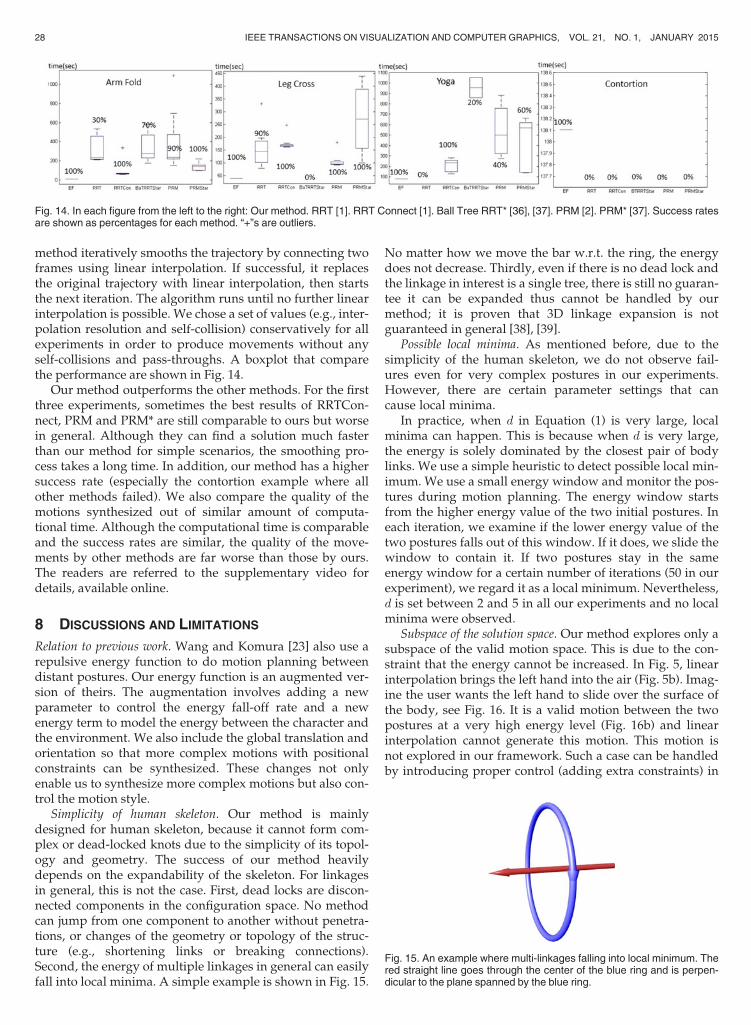
method iteratively smooths the trajectory by connecting twoframes using linear interpolation. If successful, it replacesthe original trajectory with linear interpolation, then startsthe next iteration. The algorithm runs until no further linearinterpolation is possible. We chose a set of values (e.g., inter-polation resolution and self-collision) conservatively for allexperiments in order to produce movements without anyself-collisions and pass-throughs. A boxplot that comparethe performance are shown in Fig. 14.
Our method outperforms the other methods. For the firstthree experiments, sometimes the best results of RRTCon-nect, PRM and PRM* are still comparable to ours but worsein general. Although they can find a solution much fasterthan our method for simple scenarios, the smoothing pro-cess takes a long time. In addition, our method has a highersuccess rate (especially the contortion example where allother methods failed). We also compare the quality of themotions synthesized out of similar amount of computa-tional time. Although the computational time is comparableand the success rates are similar, the quality of the move-ments by other methods are far worse than those by ours.The readers are referred to the supplementary video fordetails, available online.
8 DISCUSSIONS AND LIMITATIONS
Relation to previous work. Wang and Komura [23] also use arepulsive energy function to do motion planning betweendistant postures. Our energy function is an augmented ver-sion of theirs. The augmentation involves adding a newparameter to control the energy fall-off rate and a newenergy term to model the energy between the character andthe environment. We also include the global translation andorientation so that more complex motions with positionalconstraints can be synthesized. These changes not onlyenable us to synthesize more complex motions but also con-trol the motion style.
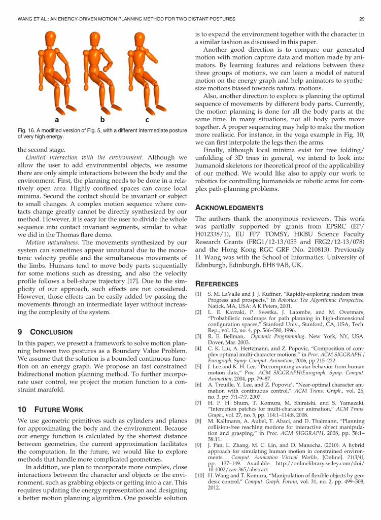
Simplicity of human skeleton. Our method is mainlydesigned for human skeleton, because it cannot form com-plex or dead-locked knots due to the simplicity of its topol-ogy and geometry. The success of our method heavilydepends on the expandability of the skeleton. For linkagesin general, this is not the case. First, dead locks are discon-nected components in the configuration space. No methodcan jump from one component to another without penetra-tions, or changes of the geometry or topology of the struc-ture (e.g., shortening links or breaking connections).Second, the energy of multiple linkages in general can easilyfall into local minima. A simple example is shown in Fig. 15.
No matter how we move the bar w.r.t. the ring, the energydoes not decrease. Thirdly, even if there is no dead lock andthe linkage in interest is a single tree, there is still no guaran-tee it can be expanded thus cannot be handled by ourmethod; it is proven that 3D linkage expansion is notguaranteed in general [38], [39].
Possible local minima. As mentioned before, due to thesimplicity of the human skeleton, we do not observe fail-ures even for very complex postures in our experiments.However, there are certain parameter settings that cancause local minima.
In practice, when d in Equation (1) is very large, localminima can happen. This is because when d is very large,the energy is solely dominated by the closest pair of bodylinks. We use a simple heuristic to detect possible local min-imum. We use a small energy window and monitor the pos-tures during motion planning. The energy window startsfrom the higher energy value of the two initial postures. Ineach iteration, we examine if the lower energy value of thetwo postures falls out of this window. If it does, we slide thewindow to contain it. If two postures stay in the sameenergy window for a certain number of iterations (50 in ourexperiment), we regard it as a local minimum. Nevertheless,d is set between 2 and 5 in all our experiments and no localminima were observed.
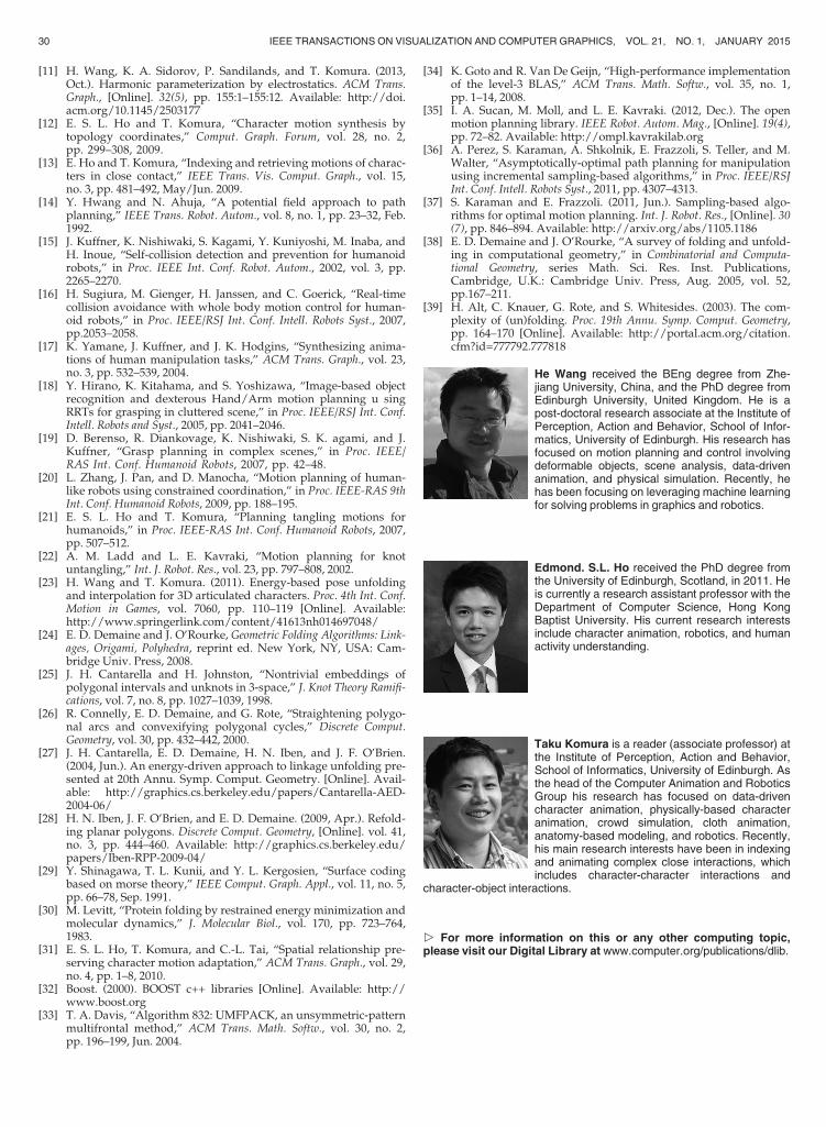
Subspace of the solution space. Our method explores only asubspace of the valid motion space. This is due to the con-straint that the energy cannot be increased. In Fig. 5, linearinterpolation brings the left hand into the air (Fig. 5b). Imag-ine the user wants the left hand to slide over the surface ofthe body, see Fig. 16. It is a valid motion between the twopostures at a very high energy level (Fig. 16b) and linearinterpolation cannot generate this motion. This motion isnot explored in our framework. Such a case can be handledby introducing proper control (adding extra constraints) in
Fig. 14. In each figure from the left to the right: Our method. RRT [1]. RRT Connect [1]. Ball Tree RRT* [36], [37]. PRM [2]. PRM* [37]. Success ratesare shown as percentages for each method. “+”s are outliers.
Fig. 15. An example where multi-linkages falling into local minimum. Thered straight line goes through the center of the blue ring and is perpen-dicular to the plane spanned by the blue ring.
28 IEEE TRANSACTIONS ON VISUALIZATION AND COMPUTER GRAPHICS, VOL. 21, NO. 1, JANUARY 2015
the second stage.Limited interaction with the environment. Although we
allow the user to add environmental objects, we assumethere are only simple interactions between the body and theenvironment. First, the planning needs to be done in a rela-tively open area. Highly confined spaces can cause localminima. Second the contact should be invariant or subjectto small changes. A complex motion sequence where con-tacts change greatly cannot be directly synthesized by ourmethod. However, it is easy for the user to divide the wholesequence into contact invariant segments, similar to whatwe did in the Thomas flare demo.
Motion naturalness. The movements synthesized by oursystem can sometimes appear unnatural due to the mono-tonic velocity profile and the simultaneous movements ofthe limbs. Humans tend to move body parts sequentiallyfor some motions such as dressing, and also the velocityprofile follows a bell-shape trajectory [17]. Due to the sim-plicity of our approach, such effects are not considered.However, those effects can be easily added by passing themovements through an intermediate layer without increas-ing the complexity of the system.
9 CONCLUSION
In this paper, we present a framework to solve motion plan-ning between two postures as a Boundary Value Problem.We assume that the solution is a bounded continuous func-tion on an energy graph. We propose an fast constrainedbidirectional motion planning method. To further incorpo-rate user control, we project the motion function to a con-straint manifold.
10 FUTURE WORK
We use geometric primitives such as cylinders and planesfor approximating the body and the environment. Becauseour energy function is calculated by the shortest distancebetween geometries, the current approximation facilitatesthe computation. In the future, we would like to exploremethods that handle more complicated geometries.
In addition, we plan to incorporate more complex, closeinteractions between the character and objects or the envi-ronment, such as grabbing objects or getting into a car. Thisrequires updating the energy representation and designinga better motion planning algorithm. One possible solution
is to expand the environment together with the character ina similar fashion as discussed in this paper.
Another good direction is to compare our generatedmotion with motion capture data and motion made by ani-mators. By learning features and relations between thesethree groups of motions, we can learn a model of naturalmotion on the energy graph and help animators to synthe-size motions biased towards natural motions.
Also, another direction to explore is planning the optimalsequence of movements by different body parts. Currently,the motion planning is done for all the body parts at thesame time. In many situations, not all body parts movetogether. A proper sequencing may help to make the motionmore realistic. For instance, in the yoga example in Fig. 10,we can first interpolate the legs then the arms.
Finally, although local minima exist for free folding/unfolding of 3D trees in general, we intend to look intohumanoid skeletons for theoretical proof of the applicabilityof our method. We would like also to apply our work torobotics for controlling humanoids or robotic arms for com-plex path-planning problems.
ACKNOWLEDGMENTS
The authors thank the anonymous reviewers. This workwas partially supported by grants from EPSRC (EP/H012338/1), EU FP7 TOMSY, HKBU Science FacultyResearch Grants (FRG1/12-13/055 and FRG2/12-13/078)and the Hong Kong RGC GRF (No. 210813). PreviouslyH. Wang was with the School of Informatics, University ofEdinburgh, Edinburgh, EH8 9AB, UK.
REFERENCES
[1] S. M. LaValle and J. J. Kuffner, “Rapidly-exploring random trees:Progress and prospects,” in Robotics: The Algorithmic Perspective.Natick, MA, USA: A K Peters, 2001.
[2] L. E. Kavraki, P. Svestka, J. Latombe, and M. Overmars,“Probabilistic roadmaps for path planning in high-dimensionalconfiguration spaces,” Stanford Univ., Stanford, CA, USA, Tech.Rep., vol. 12, no. 4, pp. 566–580, 1996.
[3] R. E. Bellman, Dynamic Programming. New York, NY, USA:Dover, Mar. 2003.
[4] C. K. Liu, A. Hertzmann, and Z. Popovic, “Composition of com-plex optimal multi-character motions,” in Proc. ACM SIGGRAPH /Eurograph. Symp. Comput. Animation, 2006, pp.215–222.
[5] J. Lee and K. H. Lee, “Precomputing avatar behavior from humanmotion data,” Proc. ACM SIGGRAPH/Eurograph. Symp. Comput.Animation, 2004, pp. 79–87.
[6] A. Treuille, Y. Lee, and Z. Popovic’, “Near-optimal character ani-mation with continuous control,” ACM Trans. Graph., vol. 26,no. 3, pp. 7:1–7:7, 2007.
[7] H. P. H. Shum, T. Komura, M. Shiraishi, and S. Yamazaki,“Interaction patches for multi-character animation,” ACM Trans.Graph., vol. 27, no. 5, pp. 114:1–114:8, 2008.
[8] M. Kallmann, A. Aubel, T. Abaci, and D. Thalmann, “Planningcollision-free reaching motions for interactive object manipula-tion and grasping,” in Proc. ACM SIGGRAPH, 2008, pp. 58:1–58:11.
[9] J. Pan, L. Zhang, M. C. Lin, and D. Manocha. (2010). A hybridapproach for simulating human motion in constrained environ-ments. Comput. Animation Virtual Worlds, [Online]. 21(3/4),pp. 137–149. Available: http://onlinelibrary.wiley.com/doi/10.1002/cav.365/abstract
[10] H. Wang and T. Komura, “Manipulation of flexible objects by geo-desic control,” Comput. Graph. Forum, vol. 31, no. 2, pp. 499–508,2012.
Fig. 16. A modified version of Fig. 5, with a different intermediate postureof very high energy.
WANG ET AL.: AN ENERGY-DRIVEN MOTION PLANNING METHOD FOR TWO DISTANT POSTURES 29
[11] H. Wang, K. A. Sidorov, P. Sandilands, and T. Komura. (2013,Oct.). Harmonic parameterization by electrostatics. ACM Trans.Graph., [Online]. 32(5), pp. 155:1–155:12. Available: http://doi.acm.org/10.1145/2503177
[12] E. S. L. Ho and T. Komura, “Character motion synthesis bytopology coordinates,” Comput. Graph. Forum, vol. 28, no. 2,pp. 299–308, 2009.
[13] E. Ho and T. Komura, “Indexing and retrieving motions of charac-ters in close contact,” IEEE Trans. Vis. Comput. Graph., vol. 15,no. 3, pp. 481–492, May/Jun. 2009.
[14] Y. Hwang and N. Ahuja, “A potential field approach to pathplanning,” IEEE Trans. Robot. Autom., vol. 8, no. 1, pp. 23–32, Feb.1992.
[15] J. Kuffner, K. Nishiwaki, S. Kagami, Y. Kuniyoshi, M. Inaba, andH. Inoue, “Self-collision detection and prevention for humanoidrobots,” in Proc. IEEE Int. Conf. Robot. Autom., 2002, vol. 3, pp.2265–2270.
[16] H. Sugiura, M. Gienger, H. Janssen, and C. Goerick, “Real-timecollision avoidance with whole body motion control for human-oid robots,” in Proc. IEEE/RSJ Int. Conf. Intell. Robots Syst., 2007,pp.2053–2058.
[17] K. Yamane, J. Kuffner, and J. K. Hodgins, “Synthesizing anima-tions of human manipulation tasks,” ACM Trans. Graph., vol. 23,no. 3, pp. 532–539, 2004.
[18] Y. Hirano, K. Kitahama, and S. Yoshizawa, “Image-based objectrecognition and dexterous Hand/Arm motion planning u singRRTs for grasping in cluttered scene,” in Proc. IEEE/RSJ Int. Conf.Intell. Robots and Syst., 2005, pp. 2041–2046.
[19] D. Berenso, R. Diankovage, K. Nishiwaki, S. K. agami, and J.Kuffner, “Grasp planning in complex scenes,” in Proc. IEEE/RAS Int. Conf. Humanoid Robots, 2007, pp. 42–48.
[20] L. Zhang, J. Pan, and D. Manocha, “Motion planning of human-like robots using constrained coordination,” in Proc. IEEE-RAS 9thInt. Conf. Humanoid Robots, 2009, pp. 188–195.
[21] E. S. L. Ho and T. Komura, “Planning tangling motions forhumanoids,” in Proc. IEEE-RAS Int. Conf. Humanoid Robots, 2007,pp. 507–512.
[22] A. M. Ladd and L. E. Kavraki, “Motion planning for knotuntangling,” Int. J. Robot. Res., vol. 23, pp. 797–808, 2002.
[23] H. Wang and T. Komura. (2011). Energy-based pose unfoldingand interpolation for 3D articulated characters. Proc. 4th Int. Conf.Motion in Games, vol. 7060, pp. 110–119 [Online]. Available:http://www.springerlink.com/content/41613nh014697048/
[24] E. D. Demaine and J. O’Rourke, Geometric Folding Algorithms: Link-ages, Origami, Polyhedra, reprint ed. New York, NY, USA: Cam-bridge Univ. Press, 2008.
[25] J. H. Cantarella and H. Johnston, “Nontrivial embeddings ofpolygonal intervals and unknots in 3-space,” J. Knot Theory Ramifi-cations, vol. 7, no. 8, pp. 1027–1039, 1998.
[26] R. Connelly, E. D. Demaine, and G. Rote, “Straightening polygo-nal arcs and convexifying polygonal cycles,” Discrete Comput.Geometry, vol. 30, pp. 432–442, 2000.
[27] J. H. Cantarella, E. D. Demaine, H. N. Iben, and J. F. O’Brien.(2004, Jun.). An energy-driven approach to linkage unfolding pre-sented at 20th Annu. Symp. Comput. Geometry. [Online]. Avail-able: http://graphics.cs.berkeley.edu/papers/Cantarella-AED-2004-06/
[28] H. N. Iben, J. F. O’Brien, and E. D. Demaine. (2009, Apr.). Refold-ing planar polygons. Discrete Comput. Geometry, [Online]. vol. 41,no. 3, pp. 444–460. Available: http://graphics.cs.berkeley.edu/papers/Iben-RPP-2009-04/
[29] Y. Shinagawa, T. L. Kunii, and Y. L. Kergosien, “Surface codingbased on morse theory,” IEEE Comput. Graph. Appl., vol. 11, no. 5,pp. 66–78, Sep. 1991.
[30] M. Levitt, “Protein folding by restrained energy minimization andmolecular dynamics,” J. Molecular Biol., vol. 170, pp. 723–764,1983.
[31] E. S. L. Ho, T. Komura, and C.-L. Tai, “Spatial relationship pre-serving character motion adaptation,” ACM Trans. Graph., vol. 29,no. 4, pp. 1–8, 2010.
[32] Boost. (2000). BOOST c++ libraries [Online]. Available: http://www.boost.org
[33] T. A. Davis, “Algorithm 832: UMFPACK, an unsymmetric-patternmultifrontal method,” ACM Trans. Math. Softw., vol. 30, no. 2,pp. 196–199, Jun. 2004.
[34] K. Goto and R. Van De Geijn, “High-performance implementationof the level-3 BLAS,” ACM Trans. Math. Softw., vol. 35, no. 1,pp. 1–14, 2008.
[35] I. A. Sucan, M. Moll, and L. E. Kavraki. (2012, Dec.). The openmotion planning library. IEEE Robot. Autom. Mag., [Online]. 19(4),pp. 72–82. Available: http://ompl.kavrakilab.org
[36] A. Perez, S. Karaman, A. Shkolnik, E. Frazzoli, S. Teller, and M.Walter, “Asymptotically-optimal path planning for manipulationusing incremental sampling-based algorithms,” in Proc. IEEE/RSJInt. Conf. Intell. Robots Syst., 2011, pp. 4307–4313.
[37] S. Karaman and E. Frazzoli. (2011, Jun.). Sampling-based algo-rithms for optimal motion planning. Int. J. Robot. Res., [Online]. 30(7), pp. 846–894. Available: http://arxiv.org/abs/1105.1186
[38] E. D. Demaine and J. O’Rourke, “A survey of folding and unfold-ing in computational geometry,” in Combinatorial and Computa-tional Geometry, series Math. Sci. Res. Inst. Publications,Cambridge, U.K.: Cambridge Univ. Press, Aug. 2005, vol. 52,pp.167–211.
[39] H. Alt, C. Knauer, G. Rote, and S. Whitesides. (2003). The com-plexity of (un)folding. Proc. 19th Annu. Symp. Comput. Geometry,pp. 164–170 [Online]. Available: http://portal.acm.org/citation.cfm?id=777792.777818
He Wang received the BEng degree from Zhe-jiang University, China, and the PhD degree fromEdinburgh University, United Kingdom. He is apost-doctoral research associate at the Institute ofPerception, Action and Behavior, School of Infor-matics, University of Edinburgh. His research hasfocused on motion planning and control involvingdeformable objects, scene analysis, data-drivenanimation, and physical simulation. Recently, hehas been focusing on leveraging machine learningfor solving problems in graphics and robotics.
Edmond. S.L. Ho received the PhD degree fromthe University of Edinburgh, Scotland, in 2011. Heis currently a research assistant professor with theDepartment of Computer Science, Hong KongBaptist University. His current research interestsinclude character animation, robotics, and humanactivity understanding.
Taku Komura is a reader (associate professor) atthe Institute of Perception, Action and Behavior,School of Informatics, University of Edinburgh. Asthe head of the Computer Animation and RoboticsGroup his research has focused on data-drivencharacter animation, physically-based characteranimation, crowd simulation, cloth animation,anatomy-based modeling, and robotics. Recently,his main research interests have been in indexingand animating complex close interactions, whichincludes character-character interactions and
character-object interactions.
" For more information on this or any other computing topic,please visit our Digital Library at www.computer.org/publications/dlib.
30 IEEE TRANSACTIONS ON VISUALIZATION AND COMPUTER GRAPHICS, VOL. 21, NO. 1, JANUARY 2015