Embed Size (px)
Citation preview
I–1
UserManual
1771–DB BasicModule
Allen-Bradley
Using This Manual 1. . . . . . . . . . . . . . . . . . . . . . . . . . . . . . .
1.1 Chapter Objectives 1. . . . . . . . . . . . . . . . . . . . . . . . . . . . . . . 1.2 What this manual contains 1. . . . . . . . . . . . . . . . . . . . . . . . . . 1.3 Audience 1. . . . . . . . . . . . . . . . . . . . . . . . . . . . . . . . . . . . . . 1.4 Definitions of major terms 1. . . . . . . . . . . . . . . . . . . . . . . . . . . 1.5 Important information 2. . . . . . . . . . . . . . . . . . . . . . . . . . . . . . 1.6 Conventions 2. . . . . . . . . . . . . . . . . . . . . . . . . . . . . . . . . . . .
Introducing the BASIC Module 1. . . . . . . . . . . . . . . . . . . . . .
2.1 Chapter Objectives 1. . . . . . . . . . . . . . . . . . . . . . . . . . . . . . . 2.2 General Features 1. . . . . . . . . . . . . . . . . . . . . . . . . . . . . . . . 2.3 Hardware Features 2. . . . . . . . . . . . . . . . . . . . . . . . . . . . . . . . 2.4 Software Features 3. . . . . . . . . . . . . . . . . . . . . . . . . . . . . . . . 2.5 Specifications 4. . . . . . . . . . . . . . . . . . . . . . . . . . . . . . . . . . .
Installing the BASIC Module 1. . . . . . . . . . . . . . . . . . . . . . .
3.1 Chapter Objectives 1. . . . . . . . . . . . . . . . . . . . . . . . . . . . . . . . 3.2 Installing the BASIC module 1. . . . . . . . . . . . . . . . . . . . . . . . . 3.2.1 Power Requirements 2. . . . . . . . . . . . . . . . . . . . . . . . . . . . . 3.2.2 Module Location in the I/O Chassis 2. . . . . . . . . . . . . . . . . . . 3.2.3 Module Keying 2. . . . . . . . . . . . . . . . . . . . . . . . . . . . . . . . . 3.2.4 Configuration Plugs 3. . . . . . . . . . . . . . . . . . . . . . . . . . . . . . 3.2.5 Module Installation 5. . . . . . . . . . . . . . . . . . . . . . . . . . . . . . . 3.2.6 Initial Start-up Procedure 5. . . . . . . . . . . . . . . . . . . . . . . . . . 3.3 Module Status LED’s 6. . . . . . . . . . . . . . . . . . . . . . . . . . . . . . 3.4 Installing the User Prom 7. . . . . . . . . . . . . . . . . . . . . . . . . . . . 3.4.1 Electrostatic Discharge 9. . . . . . . . . . . . . . . . . . . . . . . . . . . 3.5 Battery 9. . . . . . . . . . . . . . . . . . . . . . . . . . . . . . . . . . . . . . . . 3.5 Battery (continued) 10. . . . . . . . . . . . . . . . . . . . . . . . . . . . . . . .
Using the Serial Ports I–1. . . . . . . . . . . . . . . . . . . . . . . . . . . .
4.1 Chapter Objectives I–1. . . . . . . . . . . . . . . . . . . . . . . . . . . . . . . . 4.2 Using the BASIC Module Program and Peripheral
Communication Ports I–1. . . . . . . . . . . . . . . . . . . . . . . . . . . . . . 4.2.1 Pin Descriptions I–3. . . . . . . . . . . . . . . . . . . . . . . . . . . . . . . . 4.3 Program Port I–5. . . . . . . . . . . . . . . . . . . . . . . . . . . . . . . . . . . . 4.3 Program Port (continued) I–6. . . . . . . . . . . . . . . . . . . . . . . . . . . 4.3.1 Using the XOFF/XON Commands for the Program Port I–7. . . . 4.3.2 Connecting a T3/T4 Industrial Terminal to the Program Port I–8. 4.3.3 Connecting a T30 Industrial Terminal (Cat. No. 1784-T30) to the
Program Port I–9. . . . . . . . . . . . . . . . . . . . . . . . . . . . . . . . . . . .
Table of Contents
Table of Contentsii
4.3.4 Connecting a T50 Industrial Terminal (Cat. No. 1784-T50) to the Program Port I–9. . . . . . . . . . . . . . . . . . . . . . . . . . . . . . .
4.3.4.1 Configuring the Software I–10. . . . . . . . . . . . . . . . . . . . . . . . 4.3.4.2 Wiring I–10. . . . . . . . . . . . . . . . . . . . . . . . . . . . . . . . . . . . .
4.4 Peripheral Port I–11. . . . . . . . . . . . . . . . . . . . . . . . . . . . . . . . . . . 4.4.1 Using the XON/XOFF Commands for the Peripheral Port I–12. . . 4.4.2 Connecting A T30 Industrial Terminal (1784-T30)
to the Peripheral Port I–12. . . . . . . . . . . . . . . . . . . . . . . . . . . . . . 4.4.2.1 Hardware Configuration I–14. . . . . . . . . . . . . . . . . . . . . . . .
4.4.3 Connecting a 1770-SA/SB Recorder to the Peripheral Port I–15. . 4.4.4 Connecting a 1770-HC Printer to the Peripheral Port I–15. . . . . . 4.4.5 Connecting RS-422 Devices I–16. . . . . . . . . . . . . . . . . . . . . . . . 4.5 Cable Assembly Parts I–19. . . . . . . . . . . . . . . . . . . . . . . . . . . . .
Operating Functions 1. . . . . . . . . . . . . . . . . . . . . . . . . . . . .
5.1 Chapter Objectives 1. . . . . . . . . . . . . . . . . . . . . . . . . . . . . . . . 5.2 Definition of Terms 1. . . . . . . . . . . . . . . . . . . . . . . . . . . . . . . . 5.2.1 Commands 1. . . . . . . . . . . . . . . . . . . . . . . . . . . . . . . . . . . . 5.2.2 Statements 1. . . . . . . . . . . . . . . . . . . . . . . . . . . . . . . . . . . . 5.2.3 Format Statements 2. . . . . . . . . . . . . . . . . . . . . . . . . . . . . . 5.2.4 Data Format 2. . . . . . . . . . . . . . . . . . . . . . . . . . . . . . . . . . . 5.2.5 Integers 2. . . . . . . . . . . . . . . . . . . . . . . . . . . . . . . . . . . . . . 5.2.6 Constants 3. . . . . . . . . . . . . . . . . . . . . . . . . . . . . . . . . . . . . 5.2.7 Operators 3. . . . . . . . . . . . . . . . . . . . . . . . . . . . . . . . . . . . . 5.2.8 Variables 3. . . . . . . . . . . . . . . . . . . . . . . . . . . . . . . . . . . . . 5.2.9 Expressions 4. . . . . . . . . . . . . . . . . . . . . . . . . . . . . . . . . . . 5.2.10 Relational Expressions 4. . . . . . . . . . . . . . . . . . . . . . . . . . . 5.2.11 System Control Values 4. . . . . . . . . . . . . . . . . . . . . . . . . . . 5.2.12 Argument Stack 5. . . . . . . . . . . . . . . . . . . . . . . . . . . . . . . . 5.2.13 Control Stack 5. . . . . . . . . . . . . . . . . . . . . . . . . . . . . . . . . 5.3 Description of Commands 6. . . . . . . . . . . . . . . . . . . . . . . . . . . 5.3.1 Command: RUN 6. . . . . . . . . . . . . . . . . . . . . . . . . . . . . . . . 5.3.2 Command: CONT 7. . . . . . . . . . . . . . . . . . . . . . . . . . . . . . . 5.3.3 Command: LIST 7. . . . . . . . . . . . . . . . . . . . . . . . . . . . . . . . 5.3.4 Command: LIST# or LIST[ 8. . . . . . . . . . . . . . . . . . . . . . . . . 5.3.5 Command: NEW 9. . . . . . . . . . . . . . . . . . . . . . . . . . . . . . . . 5.3.6 Command: NULL [integer] 9. . . . . . . . . . . . . . . . . . . . . . . . . 5.3.7 Command: Control C 9. . . . . . . . . . . . . . . . . . . . . . . . . . . . .
5.3.7.1 Command: Disabling Control C 9. . . . . . . . . . . . . . . . . . . 5.3.8 Command: Control S 10. . . . . . . . . . . . . . . . . . . . . . . . . . . . . 5.3.9 Command: Control Q 10. . . . . . . . . . . . . . . . . . . . . . . . . . . . . 5.3.10 Overview of EPROM File Commands 10. . . . . . . . . . . . . . . . 5.3.11 Commands: RAM and ROM [integer] 10. . . . . . . . . . . . . . . . .
5.3.11.1 RAM 11. . . . . . . . . . . . . . . . . . . . . . . . . . . . . . . . . . . . . 5.3.11.2 ROM 11. . . . . . . . . . . . . . . . . . . . . . . . . . . . . . . . . . . . .
Table of Contents iii
5.3.12 Command: XFER 12. . . . . . . . . . . . . . . . . . . . . . . . . . . . . . 5.3.13 Command: PROG 12. . . . . . . . . . . . . . . . . . . . . . . . . . . . . .
5.3.13.1 User PROM Check and Description – CALL 81 13. . . . . . . 5.3.14 Command: PROG1 14. . . . . . . . . . . . . . . . . . . . . . . . . . . . . 5.3.15 Command: PROG2 14. . . . . . . . . . . . . . . . . . . . . . . . . . . . . 5.4 Description of Statements 16. . . . . . . . . . . . . . . . . . . . . . . . . . . 5.4.1 Statement: CALL [integer] 16. . . . . . . . . . . . . . . . . . . . . . . . . 5.4.2 Statement: CLEAR 16. . . . . . . . . . . . . . . . . . . . . . . . . . . . . . 5.4.3 Statement: CLEARI (clear interrupts) 16. . . . . . . . . . . . . . . . . . 5.4.4 Statement: CLEARS 17. . . . . . . . . . . . . . . . . . . . . . . . . . . . . 5.4.5 Statements: CLOCK1 and CLOCK0 17. . . . . . . . . . . . . . . . . .
CLOCK1 17. . . . . . . . . . . . . . . . . . . . . . . . . . . . . . . . . . . . . . . . . CLOCK0 17. . . . . . . . . . . . . . . . . . . . . . . . . . . . . . . . . . . . . . . . .
5.4.6 Statements: DATA – READ – RESTORE 18. . . . . . . . . . . . . . DATA 18. . . . . . . . . . . . . . . . . . . . . . . . . . . . . . . . . . . . . . . . . . . READ 18. . . . . . . . . . . . . . . . . . . . . . . . . . . . . . . . . . . . . . . . . . . RESTORE 18. . . . . . . . . . . . . . . . . . . . . . . . . . . . . . . . . . . . . . .
5.4.7 Statement: DIM 19. . . . . . . . . . . . . . . . . . . . . . . . . . . . . . . . . 5.4.8 Statements: DO – UNTIL [rel expr] 19. . . . . . . . . . . . . . . . . . . 5.4.10 Statement: END 22. . . . . . . . . . . . . . . . . . . . . . . . . . . . . . . 5.4.11 Statements: FOR – TO – (STEP) – NEXT 22. . . . . . . . . . . . . 5.4.12 Statements: GOSUB [ln num] – RETURN 23. . . . . . . . . . . . .
GOSUB 23. . . . . . . . . . . . . . . . . . . . . . . . . . . . . . . . . . . . . . . . . RETURN 24. . . . . . . . . . . . . . . . . . . . . . . . . . . . . . . . . . . . . . . .
5.4.13 Statement: GOTO [ln num] 24. . . . . . . . . . . . . . . . . . . . . . . . 5.4.14 Statements: ON [expr] GOTO [ln num], [ln num],...[ln num],
ON [expr] GOSUB[ln num], [ln num],...[ln num] 25. . . . . . . . . . . . 5.4.15 Statements: IF – THEN – ELSE 25. . . . . . . . . . . . . . . . . . . . 5.4.16 Statement: INPUT 26. . . . . . . . . . . . . . . . . . . . . . . . . . . . . . 5.4.17 Statement: LD@ [expr] 28. . . . . . . . . . . . . . . . . . . . . . . . . . . 5.4.18 Statement: LET 29. . . . . . . . . . . . . . . . . . . . . . . . . . . . . . . . 5.4.19 Statement: ONERR [ln num) 30. . . . . . . . . . . . . . . . . . . . . . . 5.4.20 Statement: ONTIME [expr],[ln num] 31. . . . . . . . . . . . . . . . . . 5.4.21 Statement: PRINT or P. 32. . . . . . . . . . . . . . . . . . . . . . . . . . 5.4.22 Special Print Formatting Statements 33. . . . . . . . . . . . . . . . .
5.4.22.1 PRINT TAB([expr]) 33. . . . . . . . . . . . . . . . . . . . . . . . . . . 5.4.22.2 PRINT SPC([expr]) 33. . . . . . . . . . . . . . . . . . . . . . . . . . . 5.4.22.3 PRINT CR 33. . . . . . . . . . . . . . . . . . . . . . . . . . . . . . . . . 5.4.22.4 PRINT USING (special characters) 34. . . . . . . . . . . . . . . 5.4.22.5 PRINT USING(Fx) 34. . . . . . . . . . . . . . . . . . . . . . . . . . . 5.4.22.6 PRINT USING(#.#) 35. . . . . . . . . . . . . . . . . . . . . . . . . . . 5.4.22.7 PRINT USlNG(0) 35. . . . . . . . . . . . . . . . . . . . . . . . . . . . 5.4.22.8 Reset Print Head Pointer – CALL 99 36. . . . . . . . . . . . . .
5.4.23 Statement: PRINT# or P.# 36. . . . . . . . . . . . . . . . . . . . . . . . 5.4.24 Statements: PH0., PH1., PH0.#, PH1.# 37. . . . . . . . . . . . . . . 5.4.25 Statement: PUSH[expr] 38. . . . . . . . . . . . . . . . . . . . . . . . . .
Table of Contentsiv
5.4.26 Statement: POP[var] 39. . . . . . . . . . . . . . . . . . . . . . . . . . . . 5.4.27 Statement: REM 40. . . . . . . . . . . . . . . . . . . . . . . . . . . . . . . 5.4.28 Statement: RETI 41. . . . . . . . . . . . . . . . . . . . . . . . . . . . . . . 5.4.19 Statement: ST@ [expr] 41. . . . . . . . . . . . . . . . . . . . . . . . . . . 5.4.30 Statement: STOP 41. . . . . . . . . . . . . . . . . . . . . . . . . . . . . . 5.4.31 Statement: STRING 42. . . . . . . . . . . . . . . . . . . . . . . . . . . . . 5.5 Description of Arithmetic, and Logical Operators
and Expressions 43. . . . . . . . . . . . . . . . . . . . . . . . . . . . . . . . . . 5.5.1 Dual Operand (dyadic) Operators 43. . . . . . . . . . . . . . . . . . . .
5.5.1.1 Comments on logical operators .AND.,.OR. and .XOR. 44. . 5.5.2 Unary Operators 45. . . . . . . . . . . . . . . . . . . . . . . . . . . . . . . .
5.5.2.1 General Purpose Operators 45. . . . . . . . . . . . . . . . . . . . . 5.5.2.2 Log Functions 46. . . . . . . . . . . . . . . . . . . . . . . . . . . . . . . 5.5.2.3 Trig Functions 46. . . . . . . . . . . . . . . . . . . . . . . . . . . . . . . 5.5.2.4 Comments on Trig Functions 47. . . . . . . . . . . . . . . . . . . .
5.5.3 Understanding Precedence of Operators 48. . . . . . . . . . . . . . . 5.5.4 How Relational Expressions Work 49. . . . . . . . . . . . . . . . . . . . 5.6 Special Operators 50. . . . . . . . . . . . . . . . . . . . . . . . . . . . . . . . 5.6.1 Special Function Operators 50. . . . . . . . . . . . . . . . . . . . . . . .
5.6.1.1 GET 50. . . . . . . . . . . . . . . . . . . . . . . . . . . . . . . . . . . . . . 5.6.1.2 TIME 50. . . . . . . . . . . . . . . . . . . . . . . . . . . . . . . . . . . . .
5.6.2 System Control Values 52. . . . . . . . . . . . . . . . . . . . . . . . . . . . 5.6.2.1 MTOP 52. . . . . . . . . . . . . . . . . . . . . . . . . . . . . . . . . . . . . 5.6.2.2 LEN 52. . . . . . . . . . . . . . . . . . . . . . . . . . . . . . . . . . . . . .
5.7 Data Transfer Support Routines 52. . . . . . . . . . . . . . . . . . . . . . 5.7.1 Update Block-Transfer-Read Buffer (timed) – CALL 2 53. . . . . . 5.7.2 Update Block-Transfer-Write Buffer (timed) – CALL 3 53. . . . . . 5.7.3 Set Block-Transfer-Write Length – CALL 4 54. . . . . . . . . . . . . . 5.7.4 Set Block-Transfer-Read Length – CALL 5 54. . . . . . . . . . . . . 5.7.5 Update Block-Transfer-Write Buffer – CALL 6 54. . . . . . . . . . . 5.7.6 Update Block-Transfer-Read Buffer – CALL 7 54. . . . . . . . . . . 5.7.7 Disable Interrupts – CALL 8 54. . . . . . . . . . . . . . . . . . . . . . . . 5.7.8 Enable Interrupts – CALL 9 55. . . . . . . . . . . . . . . . . . . . . . . . 5.7.9 Input Call Conversion Routines 55. . . . . . . . . . . . . . . . . . . . . .
5.7.9.1 3-Digit Signed, Fixed Decimal BCD to Internal Floating Point ”XXX – CALL 10 55. . . . . . . . . . . . . . . . . . . . . .
5.7.9.2 16-Bit Binary (4-digit hex) to Internal Floating Point – CALL 11 55. . . . . . . . . . . . . . . . . . . . . . . . . . . . . . . . .
5.7.9.3 4-Digit Signed Octal to Internal Floating Point ”XXXX – CALL 12 55. . . . . . . . . . . . . . . . . . . . . . . . . . .
5.7.9.4 6-Digit, Signed, Fixed Decimal BCD to Internal Floating Point ”XXXXXX – CALL 13 56. . . . . . . . . . . . . . . . . . .
5.7.9.5 4-Digit BCD to Internal Floating Point XXXX – CALL 17 56. . 5.7.10 Output Call Conversion Routines 56. . . . . . . . . . . . . . . . . . .
5.7.10.1 Internal Floating Point to 3-Digit, Signed, Fixed Decimal BCD ”XXX – CALL 20 57. . . . . . . . . . . . . . . . . . . . . . . . . . . . .
Table of Contents v
5.7.10.2 Internal Floating Point to 16-Bit Unsigned Binary (4 digit hex) – CALL 21 57. . . . . . . . . . . . . . . . . . . . . . . . . . .
5.7.10.3 Internal Floating Point to 4-Digit, Signed Octal ”XXXX–Call 22 57. . . . . . . . . . . . . . . . . . . . . . . . . . . . .
5.7.10.4 Internal Floating Point to 6-Digit, Signed, Fixed Decimal BCD ”XXXXXX – CALL 23 58. . . . . . . . . . . . . . . . . . . . . . . . .
5.7.10.5 Internal Floating Point to 3.3-digit, Signed, Fixed Decimal BCD ”XXX.XXX – CALL 26 58. . . . . . . . . . . . . . . . . . . . . . . . .
5.7.10.6 Internal Floating Point to 4-digit BCD XXXX – CALL 27 58. 5.8 Peripheral Port Support 59. . . . . . . . . . . . . . . . . . . . . . . . . . . . 5.8.1 Peripheral Port Support – Parameter Set – CALL 30 59. . . . . . . 5.8.2 Peripheral Port Support – Display Peripheral Port
Parameters –CALL 31 60. . . . . . . . . . . . . . . . . . . . . . . . . . . . . 5.8.3 Save Program to Data Recorder – CALL 32 61. . . . . . . . . . . . . 5.8.4 Verify Program with Data Recorder – CALL 33 61. . . . . . . . . . . 5.8.5 Load Program from Data Recorder – CALL 34 62. . . . . . . . . . . 5.8.6 Get Numeric Input Character from Peripheral Port – CALL 35 635.8.7 Get the Number of Characters in the Peripheral
Port Buffers – CALL 36 65. . . . . . . . . . . . . . . . . . . . . . . . . . . . . 5.8.8 Clear the Peripheral Ports Input or Output Buffer – CALL 37 65. 5.8.9 Save Labeled Program to Data Recorder
(1770-SB only) – CALL 38 65. . . . . . . . . . . . . . . . . . . . . . . . . . . 5.8.10 Load Labeled Program from Data Recorder
(1770-SB only) – CALL 39 66. . . . . . . . . . . . . . . . . . . . . . . . . . . 5.8.11 Print the Peripheral Port Output Buffer and
Pointer – CALL 110 66. . . . . . . . . . . . . . . . . . . . . . . . . . . . . . . 5.8.12 Print the Peripheral Port Input Buffer and Pointer – CALL 111 675.8.13 Reset the Peripheral Port to Default Settings – CALL 119 67. . 5.9 Wall Clock Support Calls 67. . . . . . . . . . . . . . . . . . . . . . . . . . . . 5.9.1 Setting the Wall Clock Time (Hour, Minute, Second) – CALL 40 685.9.2 Setting the Wall Clock Date (Day, Month, Year) – CALL 41 68. . 5.9.3 Set Wall Clock – Day of Week – CALL 42 68. . . . . . . . . . . . . . 5.9.4 Date/Time Retrieve String – CALL 43 69. . . . . . . . . . . . . . . . . 5.9.5 Date Retrieve Numeric (Day, Month, Year) – CALL 44 (2) 69. . . 5.9.6 Time Retrieve String – CALL 45 69. . . . . . . . . . . . . . . . . . . . . 5.9.7 Time Retrieve Number – Call 46 70. . . . . . . . . . . . . . . . . . . . . 5.9.8 Retrieve Day of Week String – CALL 47 70. . . . . . . . . . . . . . . 5.9.9 Retrieve Day of Week Numeric – CALL 48 70. . . . . . . . . . . . . . 5.9.10 Date Retrieve String – CALL 52 71. . . . . . . . . . . . . . . . . . . . 5.10 Description of String Operators 71. . . . . . . . . . . . . . . . . . . . . . 5.10.1 The ASC Operator 72. . . . . . . . . . . . . . . . . . . . . . . . . . . . . . 5.10.2 The CHR Operator 74. . . . . . . . . . . . . . . . . . . . . . . . . . . . . .
5.10.2.1 Clearing the Screen on an Allen-Bradley Industrial Terminal 74. . . . . . . . . . . . . . . . . . . . . . . . . . . . . . .
5.10.2.2 Cursor Positioning on an Industrial Terminal 75. . . . . . . . . 5.10.3 String Support Calls 75. . . . . . . . . . . . . . . . . . . . . . . . . . . . .
5.10.3.1 String Repeat – CALL 60 80. . . . . . . . . . . . . . . . . . . . . .
Table of Contentsvi
5.10.3.2 String Append (Concatenation) – CALL 61 81. . . . . . . . . . 5.10.3.3 Number to String Conversion – CALL 62 81. . . . . . . . . . . 5.10.3.4 String to Number Conversion – CALL 63 82. . . . . . . . . . . 5.10.3.5 Find a String in a String – CALL 64 83. . . . . . . . . . . . . . . 5.10.3.6 Replace a String in a String – CALL 65 84. . . . . . . . . . . . 5.10.3.7 Insert String in a String – CALL 66 85. . . . . . . . . . . . . . . . 5.10.3.8 Delete String from a String – CALL 67 86. . . . . . . . . . . . . 5.10.3.9 Determine Length of a String – CALL 68 87. . . . . . . . . . .
5.11 Memory Support Calls 87. . . . . . . . . . . . . . . . . . . . . . . . . . . . 5.11.1 ROM to RAM Program Transfer – CALL 70 88. . . . . . . . . . . . 5.11.2 ROM/RAM to ROM Program Transfer – CALL 71 88. . . . . . . 5.11.3 RAM/ROM Return – CALL 72 89. . . . . . . . . . . . . . . . . . . . . 5.11.4 Battery-backed RAM Disable – CALL 73 90. . . . . . . . . . . . . 5.11.5 Battery-backed RAM Enable – CALL 74 90. . . . . . . . . . . . . . 5.11.6 Protected Variable Storage – CALL 77 90. . . . . . . . . . . . . . . 5.12 Miscellaneous Calls 92. . . . . . . . . . . . . . . . . . . . . . . . . . . . . . 5.12.1 Program Port Baud Rate – CALL 78 92. . . . . . . . . . . . . . . . . 5.12.2 Blink the Active LED by Default – CALL 79 93. . . . . . . . . . . . 5.12.3 Check Battery Condition – CALL 80 93. . . . . . . . . . . . . . . . . 5.12.4 User PROM Check and Description – CALL 81 93. . . . . . . . . 5.12.5 Reset Print Head Pointer – CALL 99 94. . . . . . . . . . . . . . . . . 5.12.6 Print the Argument Stack – CALL 109 94. . . . . . . . . . . . . . . . 5.12.7 Print the Peripheral Port Output Buffer and
Pointer – CALL 110 94. . . . . . . . . . . . . . . . . . . . . . . . . . . . . . . 5.12.8 Print the Peripheral Port Input Buffer and
Pointer – CALL 111 94. . . . . . . . . . . . . . . . . . . . . . . . . . . . . . . . 5.12.9 Reset the Peripheral Port to Default
Settings – CALL 119 95. . . . . . . . . . . . . . . . . . . . . . . . . . . . . .
Programming 1. . . . . . . . . . . . . . . . . . . . . . . . . . . . . . . . . . .
6.1 Chapter Objectives 1. . . . . . . . . . . . . . . . . . . . . . . . . . . . . . . 6.2 Block-Transfer with the BASIC Module 1. . . . . . . . . . . . . . . . . 6.2.1 Block-Transfer-Write and Block-Transfer-Read Buffers 1. . . . 6.3 Block-Transfer with PLC-2 Family Processors 2. . . . . . . . . . . . 6.3.1 PLC-2 Processor Program 2. . . . . . . . . . . . . . . . . . . . . . . .
6.3.1.1 Rung Description 3. . . . . . . . . . . . . . . . . . . . . . . . . . . . . 6.4 PLC-3 Family Processors 5. . . . . . . . . . . . . . . . . . . . . . . . . . 6.4.1 Rung Description for Sample PLC-3 Family Ladder
Logic – Single Data Set 7. . . . . . . . . . . . . . . . . . . . . . . . . . . . . 6.5 PLC-5 Family Processors 7. . . . . . . . . . . . . . . . . . . . . . . . . . 6.5.1 Rung Description for Sample PLC-5 Family Ladder Logic 9. . 6.6. Block-Transfer Programming Tips 10. . . . . . . . . . . . . . . . . . . .
Table of Contents vii
Data Types 1. . . . . . . . . . . . . . . . . . . . . . . . . . . . . . . . . . . . .
7.1 Chapter Objectives 1. . . . . . . . . . . . . . . . . . . . . . . . . . . . . . . 7.2 Output Data Types 1. . . . . . . . . . . . . . . . . . . . . . . . . . . . . . . 7.2.1 16-bit Binary (4 Hex Digits) 1. . . . . . . . . . . . . . . . . . . . . . . . 7.2.2 3-digit, Signed, Fixed Decimal BCD 2. . . . . . . . . . . . . . . . . . 7.2.3 4-digit, Unsigned, Fixed Decimal BCD 2. . . . . . . . . . . . . . . . 7.2.4 4-digit, Signed, Octal 3. . . . . . . . . . . . . . . . . . . . . . . . . . . . . 7.2.5 6-digit, Signed, Fixed Decimal BCD 4. . . . . . . . . . . . . . . . . . 7.2.6 3.3-digit, Signed, Fixed Decimal BCD 5. . . . . . . . . . . . . . . . 7.3 Input Data Types 6. . . . . . . . . . . . . . . . . . . . . . . . . . . . . . . . .
Editing A Procedure 1. . . . . . . . . . . . . . . . . . . . . . . . . . . . . .
8.2 Chapter Objectives 1. . . . . . . . . . . . . . . . . . . . . . . . . . . . . . . 8.2 Entering the Edit Mode 1. . . . . . . . . . . . . . . . . . . . . . . . . . . . 8.3 Editing Commands/Features 1. . . . . . . . . . . . . . . . . . . . . . . . 8.3.1 Move 1. . . . . . . . . . . . . . . . . . . . . . . . . . . . . . . . . . . . . . . . 8.3.2 Replace 1. . . . . . . . . . . . . . . . . . . . . . . . . . . . . . . . . . . . . . 8.3.3 Insert 2. . . . . . . . . . . . . . . . . . . . . . . . . . . . . . . . . . . . . . . . 8.3.4 Delete 2. . . . . . . . . . . . . . . . . . . . . . . . . . . . . . . . . . . . . . . 8.3.5 Retype 2. . . . . . . . . . . . . . . . . . . . . . . . . . . . . . . . . . . . . . . 8.3.6 Exits 2. . . . . . . . . . . . . . . . . . . . . . . . . . . . . . . . . . . . . . . . 8.3.7 Renumber 2. . . . . . . . . . . . . . . . . . . . . . . . . . . . . . . . . . . . 8.4 Editing a Simple Procedure 4. . . . . . . . . . . . . . . . . . . . . . . . .
Error Messages and Anomalies 1. . . . . . . . . . . . . . . . . . . . .
9.1 Chapter Objectives 1. . . . . . . . . . . . . . . . . . . . . . . . . . . . . . . 9.2 Error Messages from BASIC 1. . . . . . . . . . . . . . . . . . . . . . . . 9.3 Error Messages from CALL Routines 3. . . . . . . . . . . . . . . . . . 9.3.1 Data Conversion CALL Error Messages 3. . . . . . . . . . . . . . 9.3.2 Peripheral Port Support CALL Error Messages 3. . . . . . . . . . 9.3.3 Wall Clock CALL Error Messages 4. . . . . . . . . . . . . . . . . . . 9.3.4 String Support CALL Error Messages 5. . . . . . . . . . . . . . . . 9.3.5 Memory Support CALL Error Messages 6. . . . . . . . . . . . . . . 9.3.6 Miscellaneous CALL Error Messages 7. . . . . . . . . . . . . . . . 9.4 Anomalies 7. . . . . . . . . . . . . . . . . . . . . . . . . . . . . . . . . . . . .
Quick Reference Guide 1. . . . . . . . . . . . . . . . . . . . . . . . . . .
Decimal/Hexadecimal/Octal/ASCII Conversion Table 1. . . . .
Basic Module Programming Hints 1. . . . . . . . . . . . . . . . . . .
BASIC Module Programming Hints 1. . . . . . . . . . . . . . . . . . . . . . .

Chapter 1
Using This Manual
Read this chapter before you use the BASIC Module. It tells you how touse this manual properly and efficiently.
This manual shows you how to install and operate your module. It givesyou information about:
hardware specifications.
installing the module.
the BASIC instruction set.
programming the module.
This manual is not a BASIC tutorial document. We assume that you arefamiliar with BASIC programming.
Before you read this manual or try to use the BASIC Module, you shouldbe familiar with the operation of the 1771 I/O structure as it relates to yourparticular processor. Refer to our Publication Index (publication numberSD499) for the appropriate Programming and Operations manual.
To make this manual easier for you to read and understand, we avoidrepeating product names where possible. We refer to the:
BASIC Language Module (Cat. No. 1771-DB) as the BASIC Module.
Industrial Terminal System (Cat. No. 1770-T3/T4) as the industrialterminal.
Data Recorder (Cat. No. 1770-SA/SB) as the 1770-SA/SB Recorder.
RS-232-C compatible devices which communicate with the BASICModule, such as the Industrial Terminal, SA/SB Recorder, computers,robots, barcode readers, or data terminals, as RS-423A/RS-232Cdevices.
1.1 Chapter Objectives
1.2 What this manual contains
1.3 Audience
1.4 Definitions of major terms
Using This ManualChapter 1
1–2
There are three different types of precautionary statements in this manual:Important, CAUTION and WARNING.
Important: used to point out specific areas of concern when operatingyour BASIC Module.
CAUTION: used to make you aware of instances where damage to yourequipment could occur.
WARNING: used to make you aware of instances where personal injurycould occur.
In this manual, we use certain notational conventions to indicatekeystrokes and items displayed on a CRT or printer. A keystroke is shownin parentheses:
(ENTER)
1.5 Important information
1.6 Conventions
Chapter 2
Introducing the BASIC Module
This chapter discusses the functions and features of the BASIC Module.When you finish reading this chapter, you should:
understand and be able to identify the hardware components of theBASIC Module.
understand the basic features and functions of the BASIC Module.
The BASIC Module (figure 2.1) provides math functions, report generationand BASIC language capabilities for any Allen-Bradley processor thatcommunicates with the 1771 I/O system using block-transfer. It provides:
basic programming using the Intel BASIC-52 language.
math functions consistent with the BASIC-52 definition.
two independently configurable serial ports capable of connecting tovarious user devices.
user accessible real-time clock with 5 ms resolution.
user accessible “wall” clock/calendar with 1 second resolution.
program generation and editing using a dumb ASCII terminal or aT3/T4 Industrial Terminal in alphanumeric mode.
program storage and retrieval using the 1770-SA/SB Recorder.
block-transfer communication capability from a PLC-2, PLC-3 orPLC-5 family processor.
on board program PROM burning.
2.1 Chapter Objectives
2.2 General Features
Introducing the BASIC ModuleChapter 2
2–2
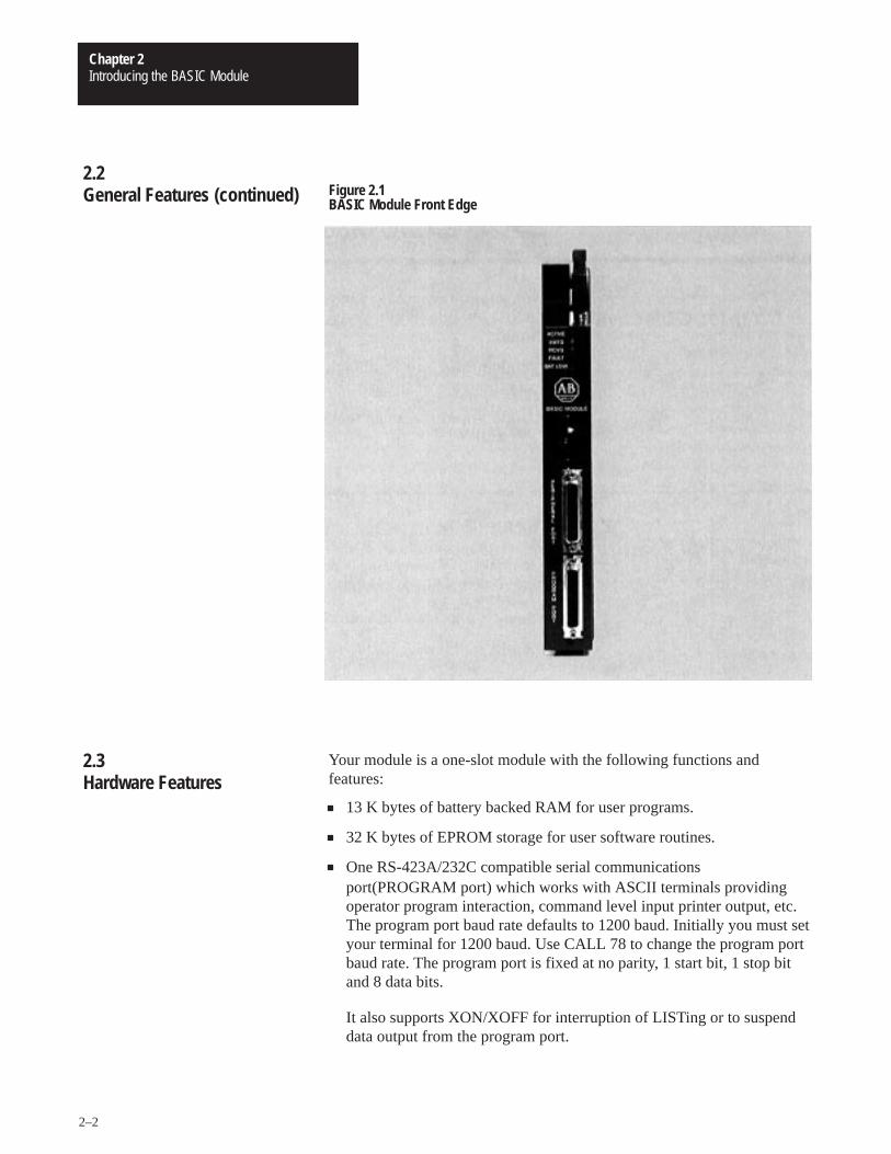
Figure 2.1BASIC Module Front Edge
Your module is a one-slot module with the following functions andfeatures:
13 K bytes of battery backed RAM for user programs.
32 K bytes of EPROM storage for user software routines.
One RS-423A/232C compatible serial communicationsport(PROGRAM port) which works with ASCII terminals providingoperator program interaction, command level input printer output, etc.The program port baud rate defaults to 1200 baud. Initially you must setyour terminal for 1200 baud. Use CALL 78 to change the program portbaud rate. The program port is fixed at no parity, 1 start bit, 1 stop bitand 8 data bits.
It also supports XON/XOFF for interruption of LISTing or to suspenddata output from the program port.
2.2General Features (continued)
2.3Hardware Features

Introducing the BASIC ModuleChapter 2
2–3
One RS-423A/232C/RS-422 compatible serial communications port(PERIPHERAL port), supporting bi-directional XON/XOFF softwarehandshaking and RTS/CTS, DTR, DSR, DCD hardware handshaking forinterfacing to printers and commercial asynchronous modems. You canchange the peripheral port configuration using a CALL 30. (Refer toSection 5.8.1). Default values are: 1 start bit, 1 stop bit, 8 bits/character,no parity, handshaking off and 1200 baud. The baud rate is jumperselectable (300 to 19.2 K bps). (Refer to Section 3.2.4 titled,“Configuration Plugs”).
Interface to the 1771 I/O rack backplane to support block-transfer.
Wall clock/calendar with battery back-up available for program access.
Battery replacement without removing the module from the I/O rack.
All power derived from the backplane (1.5 A).
Multiple BASIC modules can reside in the same I/O rack and functionindependently of each other.
Your module runs BASIC language programs in an interactive modethrough the dumb terminal/programming port interface, or on power-up.The execution of these programs allows a direct interface withprogrammable controller ladder programs.
Your module uses the following devices and features:
terminal for programming, editing, system commands, displaying dataand interactive program dialog
serial port for report generation output, upload/download to1770-SA/SB Recorder
PLC-2, PLC-3 and PLC-5 data table reads and writes usingblock-transfer
We provide routines to use both the real-time clock and thewall-clock/calendar. The wall-clock time base is seconds.
2.3Hardware Features(continued)
2.4Software Features
Isolation� The Programming Port is isolated from
the 1771 I/O backplane. (+500 V)� The Peripheral Port is isolated from
the 1771 I/O backplane. (+500 V)� The Programming Port is isolated from
the Peripheral Port. (+500 V)Communication Rates� 300, 600, 1200, 2400, 4800, 9600,
19.2 K bits� Communication rates/distances
Wall-clock accuracy� Absolute: � � 5 min/month @ 25° C� Drift � � 50 ppm/°C� Drift � � 50 ppm/year @ 25°CPort driver and receiver� Drive output +3.6 V minimum� Receiver sensitivity 200 mV minimumMath� Precision: 8 significant digits� Range: �1E-127 to�99999999E+127
� Formats: integer, decimal,hexadecimal and exponential
Module location� One 1771 I/O chassis module slotBackplane power supply load� 1.5 AEnvironmental Conditions� Operational temperature: 0°C to 60°C
(32°F to 140°F)� Storage temperature: -40°C to 85°C
(-40°F to 185°F)� Relative humidity: 5% to 95%
(non-condensing)Keying (top backplane connector)� Between 8 and 10� Between 32 and 34
� Formats: integer, decimal,hexadecimal and exponential
� Formats: integer, decimal,hexadecimal and exponential
@@@@ Drive output +3.6 V minimum
@@@@
@@@@
@@@@
Introducing the BASIC ModuleChapter 2
2–4
You can start program execution:
by entering commands at the interactive terminal.
at power-up initialization.
You can store and execute programs in RAM or EPROM. You can storeone user-program in RAM and up to 255 (depending on program size)independent user-programs simultaneously in EPROM memory.
The programs run single-task mode only. You can generate the followingdata types with the BASIC Module:
16-bit binary (4 hex digits)
3-digit, signed, fixed decimal BCD
4-digit, unsigned, fixed decimal BCD
4-digit, signed, octal
6-digit, signed, fixed decimal BCD
3.3 digit, signed, fixed decimal BCD
Refer to Chapter 7, “Data Types” for more information.
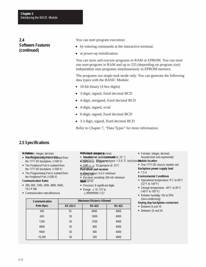
Communication Maximum Distance AllowedommunicationRate (bps) RS-232-C RS-423 RS-422
300 50 4000 4000
600 50 3000 4000
1200 50 2500 4000
4800 50 800 4000
9600 50 400 4000
19,200 50 200 4000
2.4Software Features(continued)
2.5 Specifications
Chapter 3
Installing the BASIC Module
This chapter describes how to install your BASIC module in a 1771 I/Orack. After reading this chapter you should be able to:
configure the module using the configuration plugs.
insert the module into a 1771 I/O backplane.
understand module status indicators.
install additional EPROM’s.
WARNING: Disconnect and lockout all AC power from theprogrammable controller and system power supplies beforeinstalling modules to avoid injury to personnel and damage toequipment.
Read this installation section completely before beginning. Re-check alloption selections and connections before you begin programming.
Before installing your module in the I/O chassis you must:
1. calculate the power requirements of all the modules in each chassis.(Refer to Section 3.2.1 below).
2. determine the location of the module in the I/O chassis. (Refer toSection 3.2.2 below).
3. key the backplane connectors in the I/O chassis. (Refer to Section3.2.3 below).
4. set the module configuration plugs. (Refer to Section 3.2.4 below).
3.1Chapter Objectives
3.2Installing the BASIC module
Installing the BASIC ModuleChapter 3
3–2
Your module receives its power through the 1771 I/O chassis backplanefrom the chassis power supply. It does not require any other external powersupply to function. When planning your system you must consider thepower usage of all modules in the I/O chassis to prevent overloading thechassis backplane and/or power supply. Each BASIC module requires 1.5A at +5V DC. Add this to the requirements of all other modules in the I/Ochassis.
CAUTION: Do not insert or remove modules from the I/Ochassis while system power is on. Failure to observe this rulemay result in damage to module circuitry.
You can place your module in any I/O slot of the I/O chassis except for theextreme left slot. This slot is reserved for processors or adapter modules.You can place your module in the same module group as a discrete highdensity module if you are using processors or adapters with single-slotaddressing capabilities.
Important: Certain processors restrict the placement of block-transferoutput modules. Refer to the user manual for your particular processor formore information.
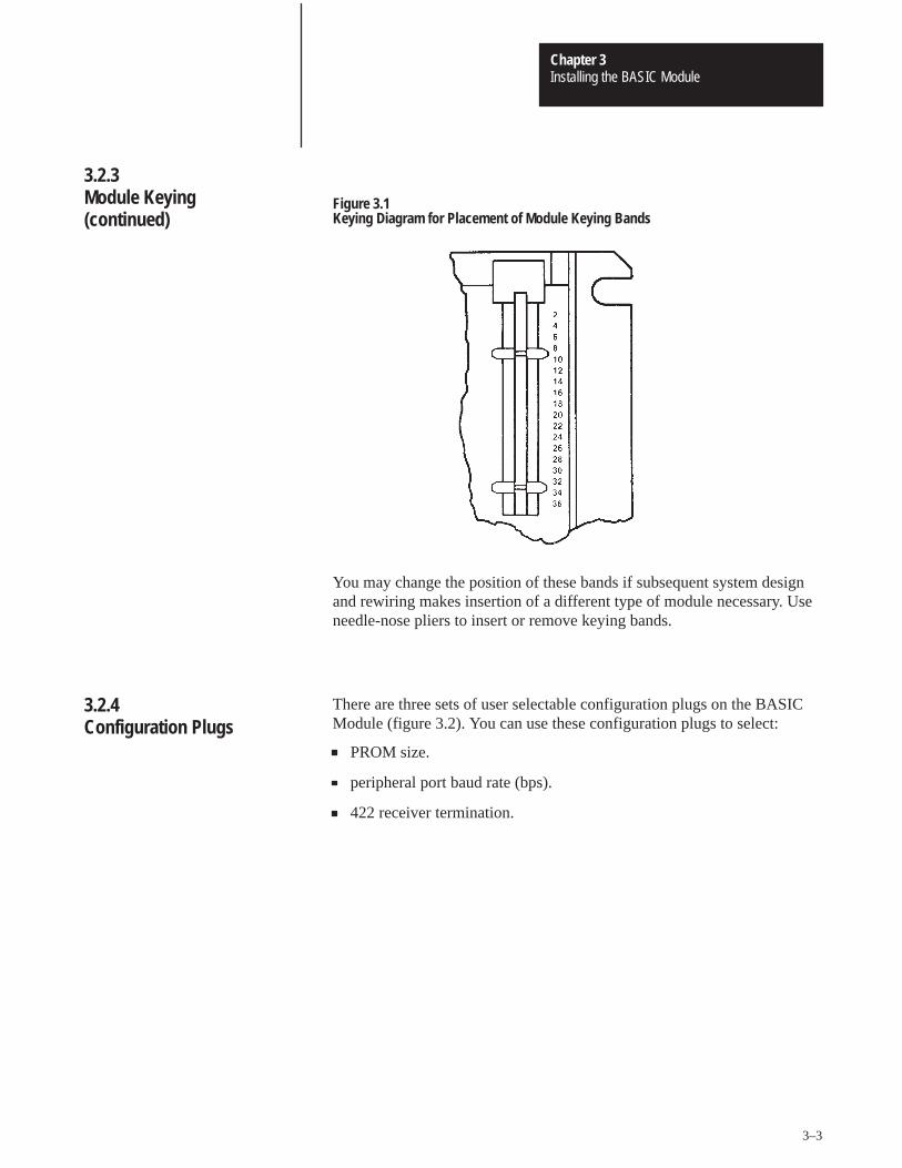
Initially you can insert your module into any I/O module slot in the I/Ochassis. However, once you designate a slot for a module you must notinsert other modules into these slots. We strongly recommend that you usethe plastic keying bands shipped with each I/O chassis, to key I/O slots toaccept only one type of module. Your module is slotted in two places onthe rear edge of the board. The position of the keying bands on thebackplane connector must correspond to these slots to allow insertion ofthe module. You may key any I/O rack connector to receive the moduleassembly. Snap the keying bands onto the upper backplane connectorsbetween the numbers printed on the backplane (figure 3.1).
Between 8 and 10
Between 32 and 34
3.2.1Power Requirements
3.2.2Module Location in the I/OChassis
3.2.3Module Keying
Installing the BASIC ModuleChapter 3
3–3
Figure 3.1Keying Diagram for Placement of Module Keying Bands
You may change the position of these bands if subsequent system designand rewiring makes insertion of a different type of module necessary. Useneedle-nose pliers to insert or remove keying bands.
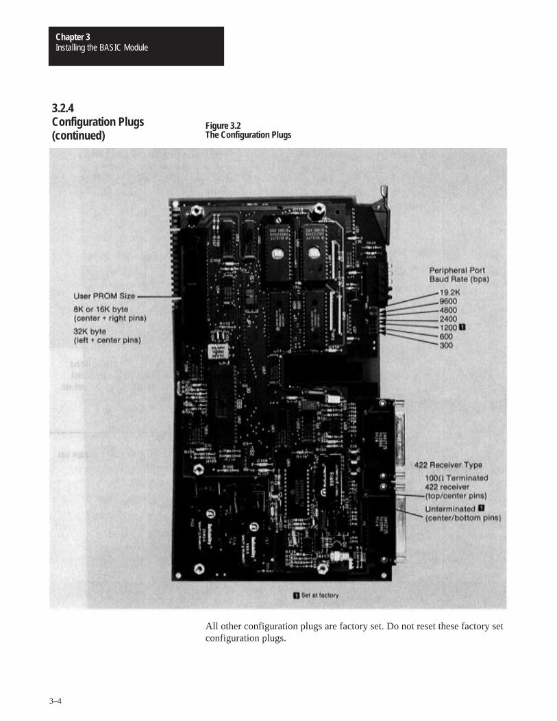
There are three sets of user selectable configuration plugs on the BASICModule (figure 3.2). You can use these configuration plugs to select:
PROM size.
peripheral port baud rate (bps).
422 receiver termination.
3.2.3Module Keying(continued)
3.2.4Configuration Plugs
Installing the BASIC ModuleChapter 3
3–4
Figure 3.2The Configuration Plugs
All other configuration plugs are factory set. Do not reset these factory setconfiguration plugs.
3.2.4Configuration Plugs(continued)
Installing the BASIC ModuleChapter 3
3–5
Now that you have determined the configuration, power requirements,location, keying and wiring for your module, you are ready to install it inthe I/O chassis.
1. Turn off power to the I/O chassis.
2. Insert your module in the I/O rack. Plastic tracks on the top andbottom of the slots guide the module into position. Do not force themodule into its backplane connector. Apply firm, even pressure onthe module to seat it properly. Note the rack, module group and slotnumbers and enter them in the module address section of theblock-transfer instructions.
3. Snap the I/O chassis latch over the module. This secures the modulein place.
You must use the following procedure when powering up the module forthe first time. This procedure is a continuation of the installation procedurepresented above.
4. Connect the cable from your program terminal to the BASIC Moduleprogram port.
CAUTION: Be sure you properly ground the system be foreturning on power. A difference in ground potential between theBASIC Module serial connectors and your program terminal orother serial device can cause damage to the equipment or loss ofmodule programs.
5. Turn on your program terminal. Select 1200 baud. If you are using anindustrial terminal, select the Alpha Numeric mode, baud rate andpress [RETURN].
6. Turn on power to the rack. The following sequence takes place:
Fault (FLT) and ACTIVE LED’s go on.
FLT and ACTIVE LED’s go out until power-up diagnostics iscomplete. Ignore any other LED activity during power-up.
ACTIVE LED goes on.
3.2.5Module Installation
3.2.6Initial Start-up Procedure
Installing the BASIC ModuleChapter 3
3–6
When the ACTIVE LED comes on observe the sign-on message displayedon the terminal followed by �READY.
You are now ready to begin BASIC programming. Refer to Chapter 6 foran example program to help you get your processor and BASIC Modulecommunicating properly.
Important: If you break communications with the module check that theterminal is set at the proper baud rate.
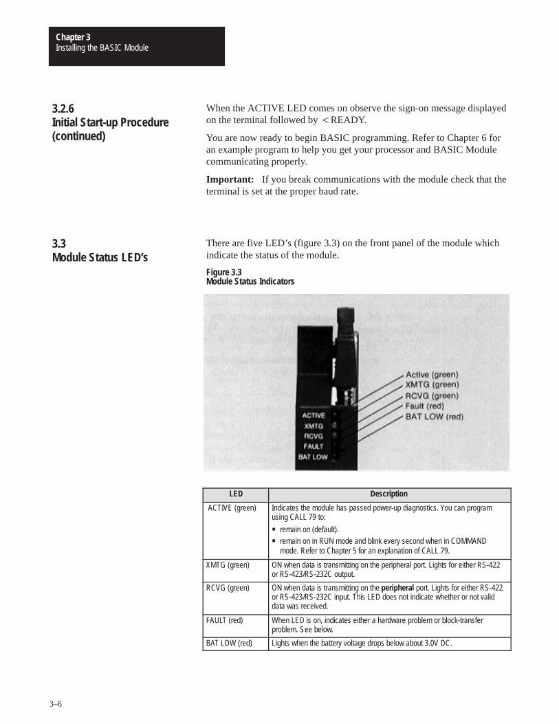
There are five LED’s (figure 3.3) on the front panel of the module whichindicate the status of the module.
Figure 3.3Module Status Indicators
LED Description
ACTIVE (green) Indicates the module has passed power-up diagnostics. You can programusing CALL 79 to:
� remain on (default).� remain on in RUN mode and blink every second when in COMMAND
mode. Refer to Chapter 5 for an explanation of CALL 79.
XMTG (green) ON when data is transmitting on the peripheral port. Lights for either RS-422or RS-423/RS-232C output.
RCVG (green) ON when data is transmitting on the peripheral port. Lights for either RS-422or RS-423/RS-232C input. This LED does not indicate whether or not validdata was received.
FAULT (red) When LED is on, indicates either a hardware problem or block-transferproblem. See below.
BAT LOW (red) Lights when the battery voltage drops below about 3.0V DC.
3.2.6Initial Start-up Procedure(continued)
3.3Module Status LED’s
Installing the BASIC ModuleChapter 3
3–7
If the FLT LED lights after the module has been operating properly checkthe following troubleshooting chart.
Problem Probable Cause Recommended Action
Module’s programming portdoes not respond
Hardware failure Send module for repair
Module’s programming portcontinues to function but FLTLED goes on and off
Problem with block-transfersbetween processor and BASICmodule
Verify ladder logic
Module’s programming portcontinues to function and FLTLED goes out when processoris switched to program mode
Module’s programming portcontinues to function and FLTLED remains on
Problem with block-transfercircuitry on the BASIC Module
Send module for repair
The BASIC Module has a 32 K byte EPROM installed (figure 3.4). Werecommend that you keep JEDEC standard 8 K, 16 K or 32 K byteEPROMs which use 12.5V DC programming voltage as spares. You canbuy 32 K byte EPROMs from Allen-Bradley (part numbers 940654-02 or9406454-03).
3.3Module Status LED’s(continued)
3.4Installing the User Prom
Installing the BASIC ModuleChapter 3
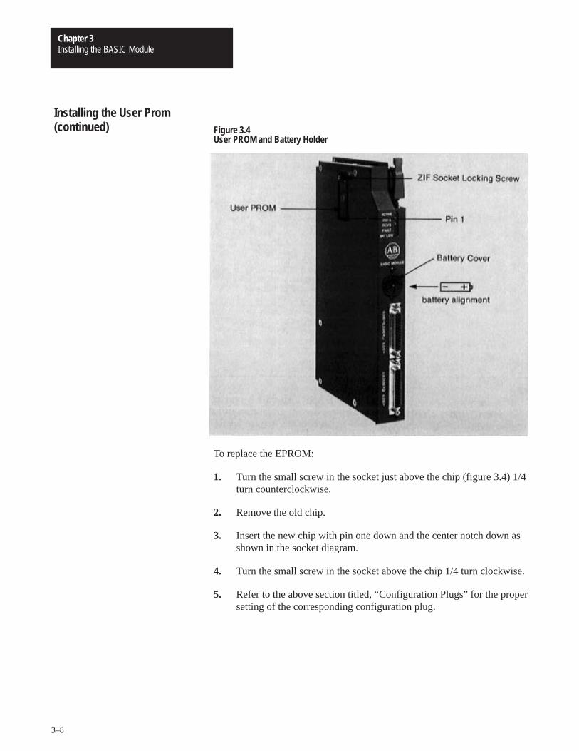
3–8
Figure 3.4User PROM and Battery Holder
To replace the EPROM:
1. Turn the small screw in the socket just above the chip (figure 3.4) 1/4turn counterclockwise.
2. Remove the old chip.
3. Insert the new chip with pin one down and the center notch down asshown in the socket diagram.
4. Turn the small screw in the socket above the chip 1/4 turn clockwise.
5. Refer to the above section titled, “Configuration Plugs” for the propersetting of the corresponding configuration plug.
Installing the User Prom(continued)
Installing the BASIC ModuleChapter 3
3–9
Electrostatic discharge can damage integrated circuits or semiconductors inthis module if you touch backplane connector pins. It can also damage themodule when you set configuration plugs and/or switches inside themodule. Avoid electrostatic damage by observing the followingprecautions:
Touch a grounded object to rid yourself of charge before handling themodule.
Do not touch the backplane connector or connector pins.
If you configure or replace internal components, do not touch othercircuit components inside the module. If available, use a static-safework station.
When not in use, keep the module in its static-shield bag.
CAUTION: Electrostatic discharge can degrade performanceor damage the module. Handle as stated above.
The 13 K bytes of user RAM and the clock/calendar are battery backed.Drain on the battery should be less than 0.5 mA DC during battery back-up(no power) and less than 50 uA while the module is powered. Battery lifeduring no-power conditions is about 2000 hours. Battery shelf life is about20,000 hours. When the BAT LOW indicator comes on the battery shouldmaintain the clock and program data for about three days. We recommendimmediate replacement.
To replace the battery (figure 3.4):
1. Place a screwdriver in the battery cover slot.
2. Press inwards slightly.
3. Rotate the screwdriver and battery cover counterclockwise 1/4 turn.
4. Release the pressure and remove the battery cover.
5. Replace the battery with the positive (+) terminal out.
6. Replace the battery cover.
3.4.1Electrostatic Discharge
3.5Battery

Installing the BASIC ModuleChapter 3
3–10
The BAT LOW indicator should go out.
You can monitor the battery low condition in revision A and revision Bmodules using a XBY(77B4H) statement. Bit 2 high indicates the batterylow condition.
With revision C modules use CALL 80 to monitor battery status.
3.5Battery (continued)
Chapter 4
Using the Serial Ports
This chapter describes how to use the program serial port and theperipheral serial port to connect terminals, Data Cartridge Recorders,Digital Cassette Recorders, printers and other compatible devices.
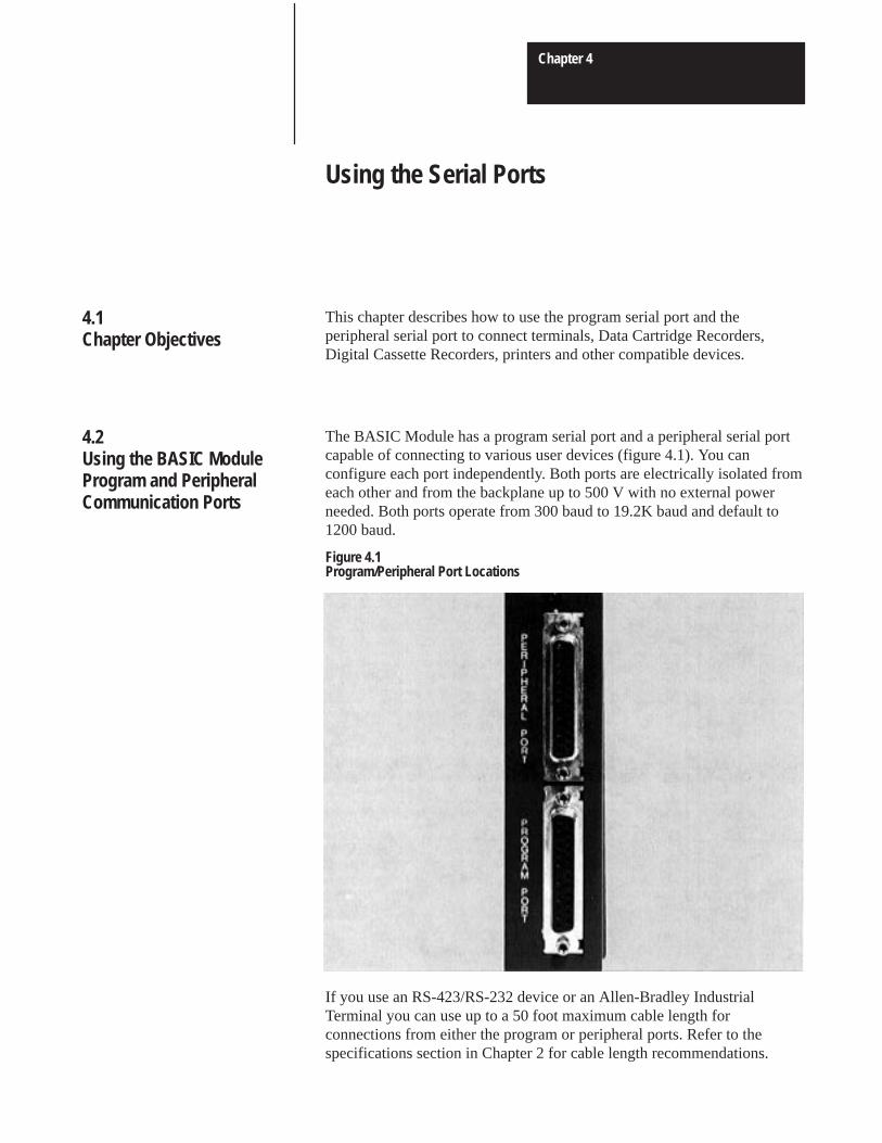
The BASIC Module has a program serial port and a peripheral serial portcapable of connecting to various user devices (figure 4.1). You canconfigure each port independently. Both ports are electrically isolated fromeach other and from the backplane up to 500 V with no external powerneeded. Both ports operate from 300 baud to 19.2K baud and default to1200 baud.
Figure 4.1Program/Peripheral Port Locations
If you use an RS-423/RS-232 device or an Allen-Bradley IndustrialTerminal you can use up to a 50 foot maximum cable length forconnections from either the program or peripheral ports. Refer to thespecifications section in Chapter 2 for cable length recommendations.
4.1Chapter Objectives
4.2Using the BASIC ModuleProgram and PeripheralCommunication Ports
Using the Serial PortsChapter 4
4–2
CAUTION: Be sure you properly ground the system beforeturning on power. A difference in ground potential between theBASIC Module serial connectors and your program terminal orother serial device can cause damage to the equipment or loss ofmodule programs.
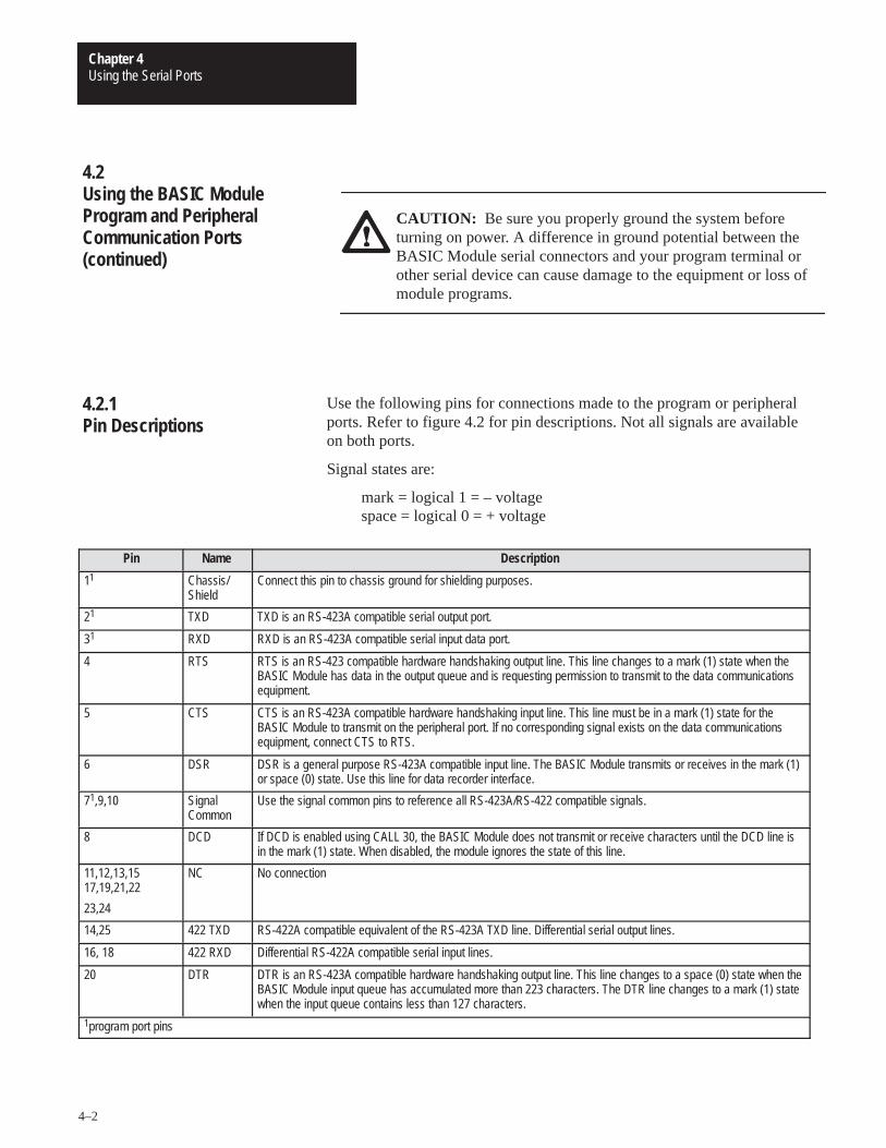
Use the following pins for connections made to the program or peripheralports. Refer to figure 4.2 for pin descriptions. Not all signals are availableon both ports.
Signal states are:
mark = logical 1 = – voltagespace = logical 0 = + voltage
Pin Name Description
11 Chassis/Shield
Connect this pin to chassis ground for shielding purposes.
21 TXD TXD is an RS-423A compatible serial output port.
31 RXD RXD is an RS-423A compatible serial input data port.
4 RTS RTS is an RS-423 compatible hardware handshaking output line. This line changes to a mark (1) state when theBASIC Module has data in the output queue and is requesting permission to transmit to the data communicationsequipment.
5 CTS CTS is an RS-423A compatible hardware handshaking input line. This line must be in a mark (1) state for theBASIC Module to transmit on the peripheral port. If no corresponding signal exists on the data communicationsequipment, connect CTS to RTS.
6 DSR DSR is a general purpose RS-423A compatible input line. The BASIC Module transmits or receives in the mark (1)or space (0) state. Use this line for data recorder interface.
71,9,10 SignalCommon
Use the signal common pins to reference all RS-423A/RS-422 compatible signals.
8 DCD If DCD is enabled using CALL 30, the BASIC Module does not transmit or receive characters until the DCD line isin the mark (1) state. When disabled, the module ignores the state of this line.
11,12,13,1517,19,21,22
23,24
NC No connection
14,25 422 TXD RS-422A compatible equivalent of the RS-423A TXD line. Differential serial output lines.
16, 18 422 RXD Differential RS-422A compatible serial input lines.
20 DTR DTR is an RS-423A compatible hardware handshaking output line. This line changes to a space (0) state when theBASIC Module input queue has accumulated more than 223 characters. The DTR line changes to a mark (1) statewhen the input queue contains less than 127 characters.
1program port pins
4.2Using the BASIC ModuleProgram and PeripheralCommunication Ports(continued)
4.2.1Pin Descriptions
Using the Serial PortsChapter 4
4–3
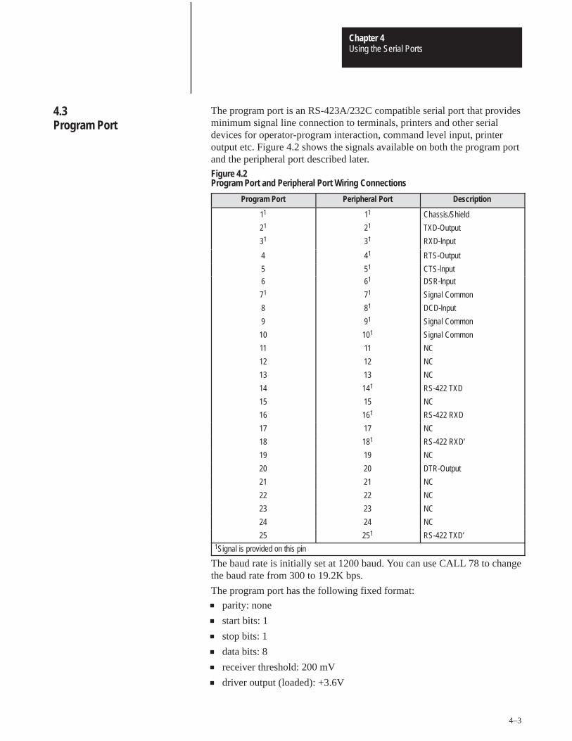
The program port is an RS-423A/232C compatible serial port that providesminimum signal line connection to terminals, printers and other serialdevices for operator-program interaction, command level input, printeroutput etc. Figure 4.2 shows the signals available on both the program portand the peripheral port described later.
Figure 4.2Program Port and Peripheral Port Wiring Connections
Program Port Peripheral Port Description
11 11 Chassis/Shield
21 21 TXD-Output
31 31 RXD-lnput
4 41 RTS-Output
5 51 CTS-lnput
6 61 DSR-lnput
71 71 Signal Common
8 81 DCD-lnput
9 91 Signal Common
10 101 Signal Common
11 11 NC
12 12 NC
13 13 NC
14 141 RS-422 TXD
15 15 NC
16 161 RS-422 RXD
17 17 NC
18 181 RS-422 RXD’
19 19 NC
20 20 DTR-Output
21 21 NC
22 22 NC
23 23 NC
24 24 NC
25 251 RS-422 TXD’1Signal is provided on this pin
The baud rate is initially set at 1200 baud. You can use CALL 78 to changethe baud rate from 300 to 19.2K bps.
The program port has the following fixed format:
parity: none
start bits: 1
stop bits: 1
data bits: 8
receiver threshold: 200 mV
driver output (loaded): +3.6V
4.3Program Port
Using the Serial PortsChapter 4
4–4
Important: The program port always resets the most significant bit of allits data inputs. The range of each byte of data is 0 to 127 (7FH). On output,the module transmits all bits as specified when using the PRINT CHR()command except for the XOFF (13H) character. The range of each byte ofdata is 0 to 255 (OFFH).
Important: The program port automatically inserts a CR, LF sequenceafter the 79th character column. Use CALL 99 to reset the column counterto zero to allow PRINT page width’s in excess of 79 characters.
You enter BASIC programs through a dumb ASCII terminal, such as anindustrial terminal in alphanumeric mode. Refer to section 4.3.2,“Connecting a T3/T4 Industrial Terminal to the Program Port”.
Use the XOFF/XON commands to disable outputs from the program portin the following way.
1. Use XOFF only on PRINT statements.
2. When XOFF is received during a PRINT, data output and programexecution are suspended immediately.
3. When XOFF is received at any other time, program executioncontinues until a PRINT is encountered. When a PRINT isencountered program execution is suspended.
4. Use XON to resume program execution.
The program port accepts uppercase or lowercase input, however, theinput receiver changes all commands, keywords or variables to uppercase before storing in memory, thus:
�10 print “hello”(CR)
appears as
10 PRINT “hello”
when listed.
4.3Program Port (continued)
4.3.1Using the XOFF/XONCommands for theProgram Port
Using the Serial PortsChapter 4
4–5
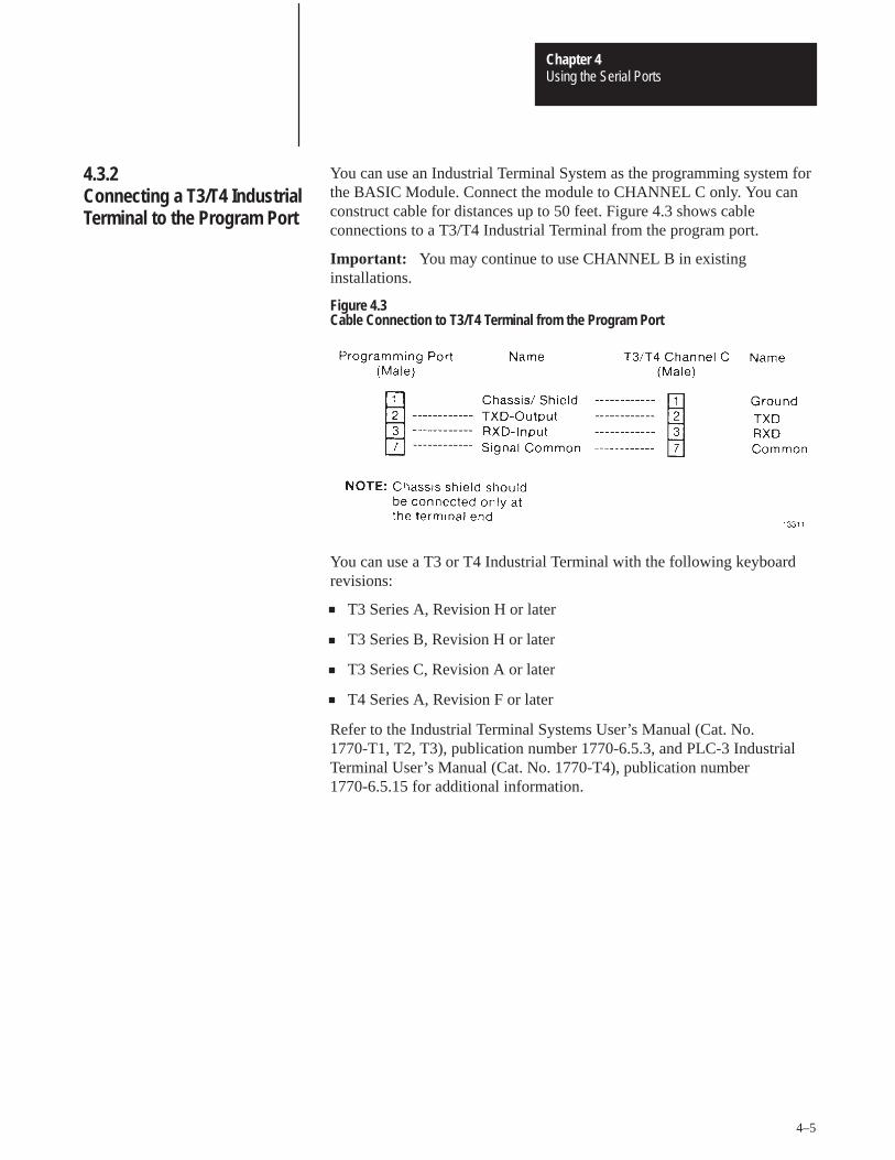
You can use an Industrial Terminal System as the programming system forthe BASIC Module. Connect the module to CHANNEL C only. You canconstruct cable for distances up to 50 feet. Figure 4.3 shows cableconnections to a T3/T4 Industrial Terminal from the program port.
Important: You may continue to use CHANNEL B in existinginstallations.
Figure 4.3Cable Connection to T3/T4 Terminal from the Program Port
You can use a T3 or T4 Industrial Terminal with the following keyboardrevisions:
T3 Series A, Revision H or later
T3 Series B, Revision H or later
T3 Series C, Revision A or later
T4 Series A, Revision F or later
Refer to the Industrial Terminal Systems User’s Manual (Cat. No.1770-T1, T2, T3), publication number 1770-6.5.3, and PLC-3 IndustrialTerminal User’s Manual (Cat. No. 1770-T4), publication number1770-6.5.15 for additional information.
4.3.2Connecting a T3/T4 IndustrialTerminal to the Program Port
Using the Serial PortsChapter 4
4–6
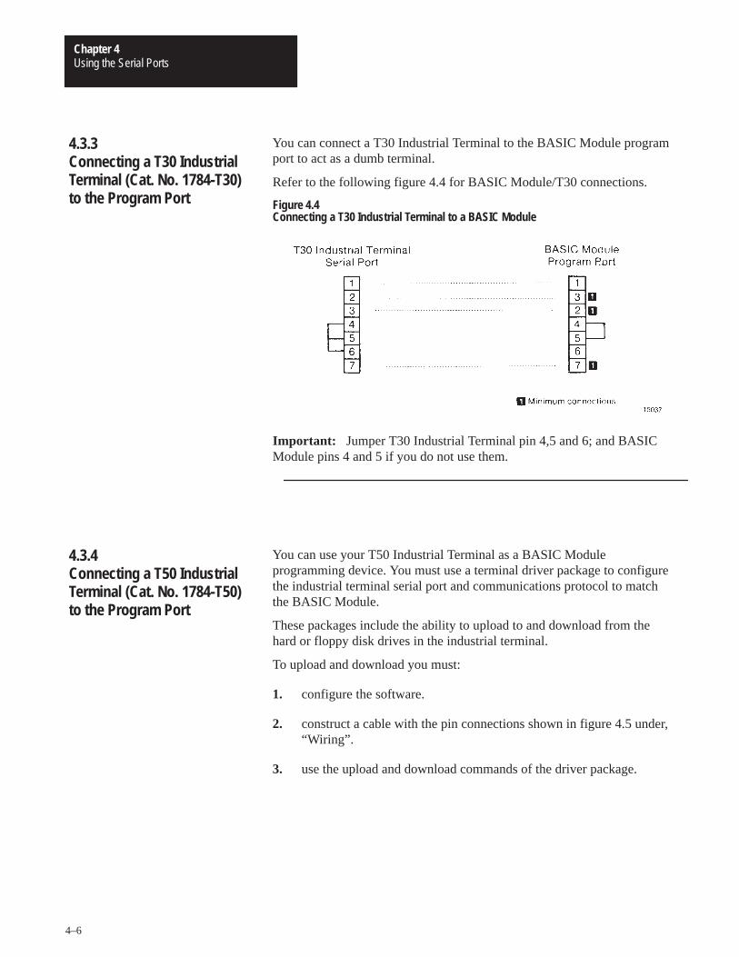
You can connect a T30 Industrial Terminal to the BASIC Module programport to act as a dumb terminal.
Refer to the following figure 4.4 for BASIC Module/T30 connections.
Figure 4.4Connecting a T30 Industrial Terminal to a BASIC Module
Important: Jumper T30 Industrial Terminal pin 4,5 and 6; and BASICModule pins 4 and 5 if you do not use them.
You can use your T50 Industrial Terminal as a BASIC Moduleprogramming device. You must use a terminal driver package to configurethe industrial terminal serial port and communications protocol to matchthe BASIC Module.
These packages include the ability to upload to and download from thehard or floppy disk drives in the industrial terminal.
To upload and download you must:
1. configure the software.
2. construct a cable with the pin connections shown in figure 4.5 under,“Wiring”.
3. use the upload and download commands of the driver package.
4.3.3Connecting a T30 IndustrialTerminal (Cat. No. 1784-T30)to the Program Port
4.3.4Connecting a T50 IndustrialTerminal (Cat. No. 1784-T50)to the Program Port
Using the Serial PortsChapter 4
4–7
4.3.4.1Configuring the Software
Configure the driver package for compatibility with the BASIC Module bysetting:
baud rate – 9600 baud recommended
parity – none
data bits – 8
start bits – 1
stop bits – 1
To download to the BASIC Module, you must use a line wait function. Theindustrial terminal waits for the “�” BASIC Module prompt beforesending the next line to the module. You must enter a line delay of 1.5seconds for terminal drivers that do not have the “wait for character”function, so that you do not lose subsequent lines. Most drivers allowstorage of the complete set of parameters in a file for later recall.
The industrial terminal stores the BASIC Module program in a text file onthe hard or floppy disc depending on where you store the terminal driverpackage. We recommend you store the driver package on the hard drive toincrease execution speed. Most driver packages have upload and downloadcapability. Refer to the driver documentation for these commands.
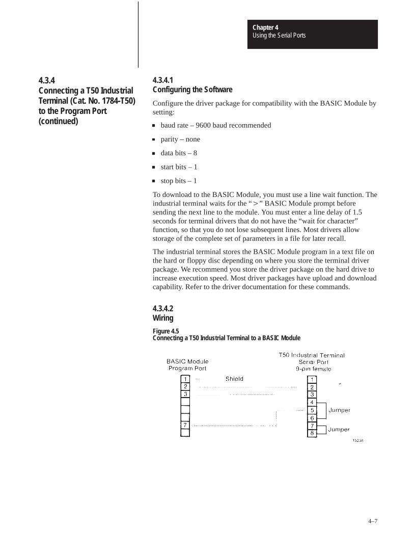
4.3.4.2Wiring
Figure 4.5Connecting a T50 Industrial Terminal to a BASIC Module
4.3.4Connecting a T50 IndustrialTerminal (Cat. No. 1784-T50)to the Program Port(continued)
Using the Serial PortsChapter 4
4–8
The peripheral port is an asynchronous serial communication channelcompatible with RS-423A/232C or RS-422 interfaces. It uses bi-directionalXON/XOFF software handshaking and RTS/CTS, DTR, DSR, DCDhardware handshaking for interfacing with printers, terminals andcommercial asynchronous modems. Use a CALL routine to changeperipheral port configuration. Configure the baud rate (300 to 19.2K bps)by setting a configuration plug. Refer to figure 3.2 for configuration pluglocations.
In addition, the peripheral port has the following format requirements:
configurable parity: odd, even or none
fixed start bits: 1
configurable stop bits: 1, 1.5 or 2
configurable data bits: 5,6,7 or 8
receiver threshold: 200 mV
driver output (loaded): +3.6V
Defaults are 1 start bit, 1 stop bit, 8 bits/character, no parity, handshakingoff and 1200 baud.
When you select 8 bits/character you have full access to all 8 bits of eachcharacter on both input and output data bytes.
Refer to figure 4.2 for peripheral port wiring connections.
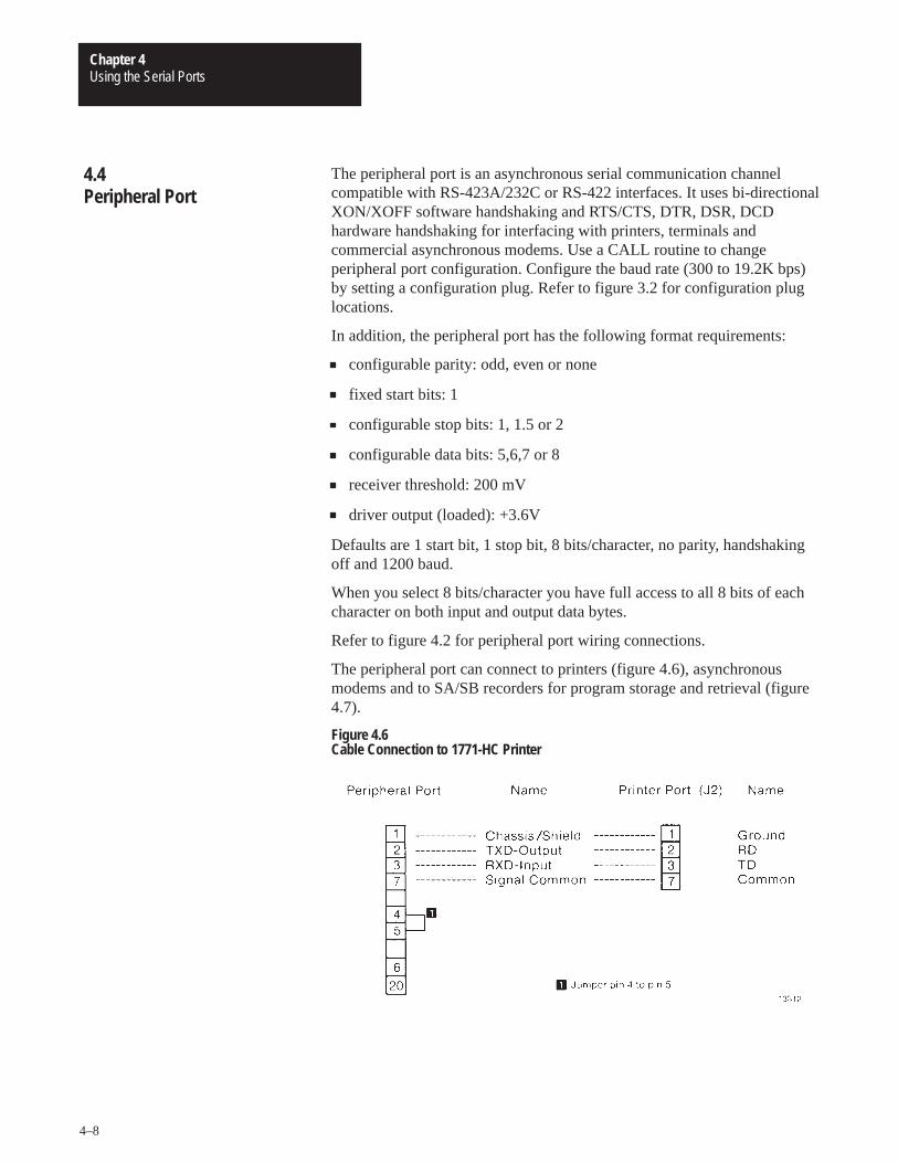
The peripheral port can connect to printers (figure 4.6), asynchronousmodems and to SA/SB recorders for program storage and retrieval (figure4.7).
Figure 4.6Cable Connection to 1771-HC Printer
4.4Peripheral Port
Using the Serial PortsChapter 4
4–9
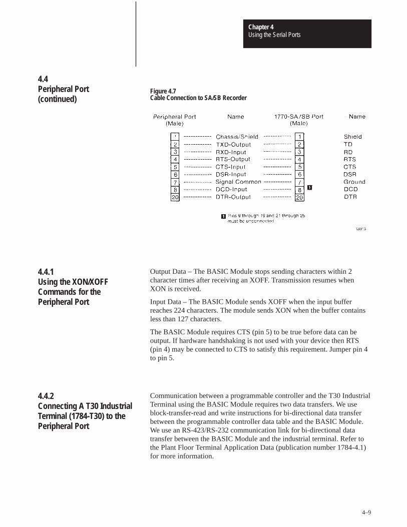
Figure 4.7Cable Connection to SA/SB Recorder
Output Data – The BASIC Module stops sending characters within 2character times after receiving an XOFF. Transmission resumes whenXON is received.
Input Data – The BASIC Module sends XOFF when the input bufferreaches 224 characters. The module sends XON when the buffer containsless than 127 characters.
The BASIC Module requires CTS (pin 5) to be true before data can beoutput. If hardware handshaking is not used with your device then RTS(pin 4) may be connected to CTS to satisfy this requirement. Jumper pin 4to pin 5.
Communication between a programmable controller and the T30 IndustrialTerminal using the BASIC Module requires two data transfers. We useblock-transfer-read and write instructions for bi-directional data transferbetween the programmable controller data table and the BASIC Module.We use an RS-423/RS-232 communication link for bi-directional datatransfer between the BASIC Module and the industrial terminal. Refer tothe Plant Floor Terminal Application Data (publication number 1784-4.1)for more information.
4.4Peripheral Port(continued)
4.4.1Using the XON/XOFFCommands for thePeripheral Port
4.4.2Connecting A T30 IndustrialTerminal (1784-T30) to thePeripheral Port
Using the Serial PortsChapter 4
4–10
4.4.2.1 Hardware Configuration
You must configure the BASIC Module peripheral port and the T30Industrial Terminal serial port in the same way for proper communicationsto occur. We configure the peripheral port on the BASIC Module asfollows:
Baud rate 1200 bps
Parity disabled
Duplex full (default setting)
Bits per character 8
Stop bits 1
Handshaking disabled
Configure the T30 Industrial Terminal serial port the same way.
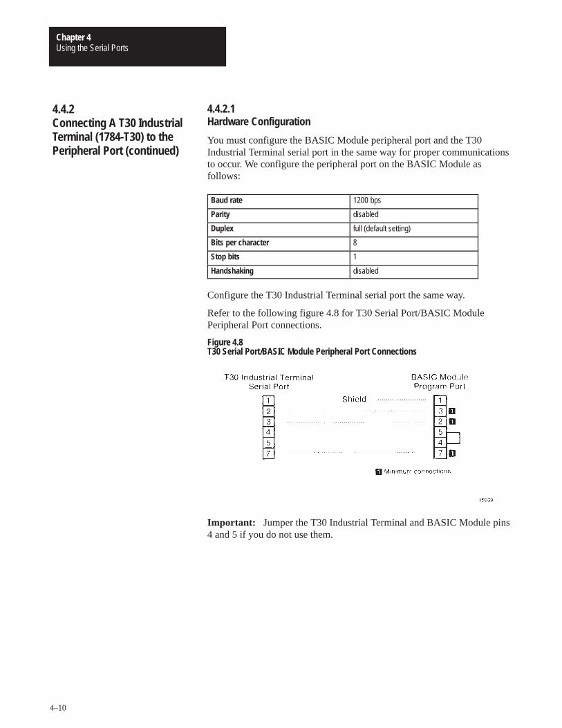
Refer to the following figure 4.8 for T30 Serial Port/BASIC ModulePeripheral Port connections.
Figure 4.8T30 Serial Port/BASIC Module Peripheral Port Connections
Important: Jumper the T30 Industrial Terminal and BASIC Module pins4 and 5 if you do not use them.
4.4.2Connecting A T30 IndustrialTerminal (1784-T30) to thePeripheral Port (continued)
Using the Serial PortsChapter 4
4–11
You can use a 1770-SB Data Cartridge Recorder or 1770-SA DigitalCassette Recorder to save and load BASIC programs to the BASICModule. Figure 4.6 shows cable pin connections. Use the connectionsshown in figure 4.6 otherwise improper operation could occur. Note thatthe standard cable does not connect properly with the BASIC Module.Refer to the user manuals for the 1770-SB (publication number1770-6.5.4) and 1770-SA (publication number 1770-6.5.1) for moreinformation on these recorders.
It is not necessary to set the peripheral port parameters (except baud rate)before CALLing the recorder interface routines. This is done automaticallyby the software. The parameters are returned to their original state whenthe routine is complete.
You can find more information on saving and loading programs in Chapter6 of this manual.
Important: STR LINK II and III Recorders do not function like SA/SBrecorders. Do not use them with the BASIC Module.
You can connect a 1770-HC Printer to the peripheral port for programlisting, report generation etc. Figure 4.7 shows cable pin connections.Refer to your printer product manual for more information.
We recommend enabling XON/XOFF on the peripheral port (see Chapter 5section titled, “Peripheral Port Support – Parameter Set”) and selectingXON/XOFF(DEC) protocol on the 1770-HC Printer (switch selectable).Refer to your printer manual. You can find more information on printingreports and listing programs in Chapter 5 of this manual.
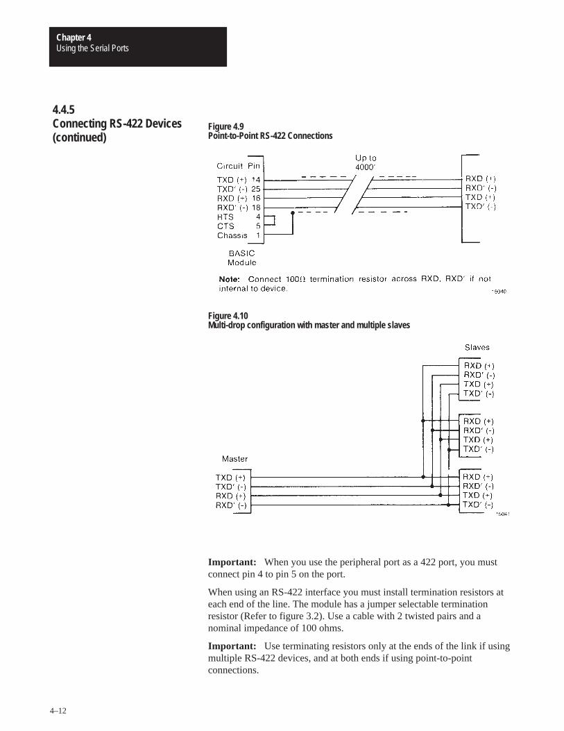
The BASIC Module can communicate with various RS-422 devices.RS-422 signals for both sending and receiving data are located on themodule’s peripheral port. Figure 4.9 shows point-to-point signalconnections. The RS-422 port floats (i.e no voltages are applied to theoutput) when it is not sending characters. This allows you to connect twotransmitting devices on the same line. Also, you can connect more than onedevice in a multi-drop configuration (figure 4.10).
4.4.3Connecting a 1770-SA/SBRecorder to the PeripheralPort
4.4.4Connecting a 1770-HCPrinter to the Peripheral Port
4.4.5Connecting RS-422 Devices
Using the Serial PortsChapter 4
4–12
Figure 4.9Point-to-Point RS-422 Connections
Figure 4.10Multi-drop configuration with master and multiple slaves
Important: When you use the peripheral port as a 422 port, you mustconnect pin 4 to pin 5 on the port.
When using an RS-422 interface you must install termination resistors ateach end of the line. The module has a jumper selectable terminationresistor (Refer to figure 3.2). Use a cable with 2 twisted pairs and anominal impedance of 100 ohms.
Important: Use terminating resistors only at the ends of the link if usingmultiple RS-422 devices, and at both ends if using point-to-pointconnections.
4.4.5Connecting RS-422 Devices(continued)
Using the Serial PortsChapter 4
4–13
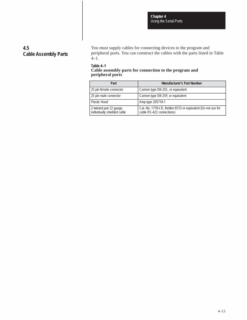
You must supply cables for connecting devices to the program andperipheral ports. You can construct the cables with the parts listed in Table4–1.
Table 4–1Cable assembly parts for connection to the program andperipheral ports
Part Manufacturer’s Part Number
25 pin female connector Cannon type DB-25S, or equivalent
25 pin male connector Cannon type DB-25P, or equivalent
Plastic Hood Amp type 205718-1
2 twisted pair 22 gauge,individually shielded cable
Cat. No. 1778-CR, Belden 8723 or equivalent (Do not use forcable RS-422 connections)
4.5Cable Assembly Parts
Chapter 5
Operating Functions
After reading this chapter you should be familiar with the BASICinstruction set and be ready to begin BASIC programming.�This chapteris a reference section�to help you with module programming. Youshould�already�be familiar with BASIC programming.
The following sections define the following terms: commands, statements,format�statements,�data format,�integers, constants, operators,variables, expressions, relational expressions,�system control�values,argument stack and control stack.
The BASIC module operates�in two modes, the�command or directmode�and the interpreter�or run mode. You can only enter commandswhen the�processor is in the command or direct�mode. This�documentuses�the terms run mode and command mode�to refer�to the twodifferent�operation�modes.
A BASIC program consists�of statements. Every statement begins�witha line�number, followed�by a statement body, and terminated�with�acarriage�return (cr), or a colon (:) in the case of multiple�statements perline.�There are three types of statements: assignments, input/output�andcontrol.
Every line in a program must have�a statement line�number rangingbetween�0 and 65535�inclusive.�BASIC uses�this to order theprogram statements in sequence.
You can use a statement number only�once in a program.
BASIC automatically�orders�statements in ascending order.
A statement�may not contain more than�79 characters.
BASIC ignores�blanks (spaces) and automatically inserts them duringa LIST command.
5.1Chapter Objectives
5.2Definition of Terms
5.2.1Commands
5.2.2Statements
Operating FunctionsChapter 5
5–2
You may put more than�one statement on a line, if separated by acolon�(:). You can use only one statement number per�line.
You can enter lower case characters�in the COMMAND mode. Anykeywords, commands, variable and array names entered in lower casechange to upper case when stored�in memory.
You can use format�statements within the print�statement. The formatstatements�include�TAB( (|expr|),�SPC([expr]), USING(specialsymbols), and CR (carriage return with no line feed).
You can represent the following range of numbers in�the BASIC module:+1E–127�to +.99999999E+127
There are eight�significant�digits.�Numbers are�internally roundedto�fit this precision. You can�enter and display numbers in�fourformats: integer,�decimal, hexadecimal and exponential.
Example:�129, 34.98, 0A6EH, 1.23456E+3
In the BASIC module,�integers�are numbers that�range from 0 to 65535 or OFFFFH. You�can�enter all integers in either decimal orhexadecimal�format. You indicate�a hexadecimal number by placing thecharacter�“H” after the number (e.g. 170H). If the hexadecimal numberbegins�with A – F, then it must be preceded by a zero (i.e. You must enterA567H as OA567H). When an�operator, such as .AND. requires aninteger, the BASIC module truncates�the fraction�portion of the numberso it fits the integer format. We refer�to integers and line numbers as:
[integer] – [ln-num]
5.2.2Statements (continued)
5.2.3Format Statements
5.2.4Data Format
5.2.5Integers
Operating FunctionsChapter 5
5–3
A constant is a real�number that ranges from +1E–127 to +.99999999E+127. A constant�can be an integer.�We refer to constants as: [const]
An operator performs a predefined�operation on variables and/orconstants. Operators�require�either one or two operands. Typical twooperand or dyadic operators include ADD (+),�SUBTRACT (–),MULTIPLY (*)�and DIVIDE(/).�We call�operators that require�onlyone operand, unary operators. Some typical�unary operators are SIN,COS and ABS.
A variable can be:
a letter (e.g. A, X,I)
a letter followed by a one dimensioned�expression, (e.g. J(4), GA(A +6), I(10*SIN(X))
a letter followed by a number followed by a one dimensionedexpression�(e.g.�A1(8), P7(10*SIN(X)), W8(A + B).
a letter followed by a number or letter�(e.g. AA, AC, XX,�A1, X3,G8) except�for the following�combinations:�CR, DO, lE, IF, IP,ON, PI, SP, TO, UI and UO.
We refer to variables that include�a one dimensioned expression [expr] asdimensioned or arrayed variables.�We refer�to variables�that contain aletter�or a letter and a number as scalar variables. Any variables enteredin lower case are changed�to�upper case. We refer�to variables as:
[var].
The BASIC module�allocates variables�in a “static” manner. Thismeans that�the first time a variable�is used, BASIC allocates a portionof memory (8 bytes)�specifically�for that variable. This memory cannotbe de-allocated�on a variable to variable basis. This means that�if youexecute�a statement (e.g.�Q 3), you cannot�tell BASIC�that thevariable Q no longer exists to “free up” the 8 bytes of memory thatbelong to Q. You can�clear�the memory allocated�to variables byexecuting a CLEAR statement.�The CLEAR statement “frees” allmemory allocated�to variables.
5.2.6Constants
5.2.7Operators
5.2.8Variables
Operating FunctionsChapter 5
5–4
Important: The BASIC Module requires less time to find a scalarvariable because there is no expression�to evaluate. If you want to�run aprogram as�fast as possible,�use dimensioned�variables only whennecessary. Use scalars�for intermediate variables and assign the finalresult to a dimensioned�variable. Also, put the most frequently�usedvariables�first. Variables defined first�require the least amount of timeto locate.
An expression�is a logical�mathematical�expression that involvesoperators (both unary and dyadic),�constants and variables.�Expressionsare simple or complex, (e.g. 12*EXP(A)/100, H(1)�+ 55, or(SIN(A)*SIN(A)+COS(A)* COS(A)/2).�A “stand alone”�variable [var]or constant [const] is also considered an expression. We refer�toexpressions as:
[expr].
Relational�expressions involve�the operators�EQUAL (=),�NOTEQUAL (��), GREATER THAN�OR�EQUAL TO�(�=), andLESS THAN OR�EQUAL TO (�=). You use them in control statementsto test a condition�(i.e. IF A �100 THEN...). Relational�expressionsalways require two operands.�We refer to relational expressions�as:
[rel expr].
The system control values include�the following:
LEN (returns the length of your program).
MTOP (the last memory location assigned to BASIC).
See the following�Section�5.6.2�titled, “System Control Values” formore information.
5.2.8Variables (continued)
5.2.9Expressions
5.2.10Relational Expressions
5.2.11System Control Values
Operating FunctionsChapter 5
5–5
The argument stack (A-stack) stores all constants that the BASIC Moduleis currently using. Operations such as add, subtract,�multiply�and dividealways operate�on the first two numbers on�the argument�stack�andreturn�the result to the stack.�The argument�stack�is 203 bytes long.Each floating point�number placed on the stack requires�6 bytes ofstorage. The argument stack can hold up to 33 floating�point numbersbefore�overflowing.
The control stack (C-stack)�stores all information�associated with loopcontrol (i.e. DO-WHILE, DO-UNTIL,�FOR-NEXT, BASIC subroutinesand “PUSHed” or “POPed” values). The control�stack is 157 bytes long.DO-WHILE and�DO-UNTIL loops�use 3 bytes of control�stack.FOR-NEXT loops�use 17 bytes.�The control�stack contains�enoughspace�for up to 9 nestings�of control�loops.
5.2.12Argument Stack
5.2.13Control Stack
Operating FunctionsChapter 5
5–6
The�following�sections list and describe�the commands�you canuse with the BASIC Module.
Action Taken:�After you type RUN, all variables�are set equal tozero,�all BASIC�evoked�interrupts�are cleared and programexecution begins with the first line number of the selected program. TheRUN command and the�GOTO statement are the only way you can placethe BASIC Module�interpreter�into the RUN mode�from theCOMMAND mode. You can terminate program execution�at any time bytyping a Control C on�the�console device.
Variations:�Some BASIC interpreters allow a line number to follow theRUN command�(i.e.�RUN 100). The BASIC�Module does not permitthis variation on the RUN command. Execution begins with the first linenumber. To obtain a function similar to the RUN[ln num] command,�usethe GOTO[ln�num] statement�in the direct mode. See statementGOTO.
Example:
�10 FOR I=1 TO 3 �20 PRINT I �30 NEXT�I �40 END �RUN
12 3
READY�
5.3Description of Commands
5.3.1Command: RUN
Operating FunctionsChapter 5
5–7
Action�Taken: If�you stop a program by�typing a Control C on theconsole�device or by execution�of a STOP statement,�you can resumeexecution of the program by typing�CONT. If�you enter�a Control�Cduring the execution�of a CALL routine�you cannot�CONTinue.Between�the stopping and the re-starting of the program you�maydisplay the values of variables�or change the�values of variables.However, you cannot CONTinue if�the program is�modified�duringthe STOP or after�an error.
Example:
�10 FOR I=1 TO 10000 �20 PRINT�I �30 PRINT�I �40 END �RUN
12 3 4 5– (TYPE CONTROL�C�ON CONSOLE)
STOP – IN LINE 20
READY �PRINT I
6
�I=10
�CONT 10 11 12
Action�taken: The LIST command prints the program to�the consoledevice. Spaces are inserted after the line number, and before�and afterstatements.�This helps in the debugging of BASIC Module programs.You can�terminate the “listing”�of a program at anytime�by typing aControl�C on the console device. You can interrupt and continue�thelisting using Control S and Control Q.
5.3.2Command: CONT
5.3.3Command: LIST
Operating FunctionsChapter 5
5–8
Variations: Two variations of the LIST command are possible with theBASIC Module.
They are:
1. LIST [ln num] (cr)�and
2. LIST [ln num] – [ln num] (cr)
The first�variation�causes the program to print�from the designatedline�number (integer) to the end of the program. The second variationcauses the program to print from the first line number (integer)�to thesecond line�number (integer).
Important: You must�separate�the two line�numbers with�a dash(–).
Example:
READY �LIST �10 PRINT “LOOP PROGRAM” �20 FOR I=1 TO 3 �30 PRINT I �40 NEXT I �50 END
READY �LIST 30 �30 PRINT I �40 NEXT I �50 END
READY �LIST 20–40 �20 FOR I=1 TO 3 �30 PRINT I �40 NEXT I
Action�taken: The LIST#�or LIST@ command lists the program tothe device attached to the peripheral port (LIST device).�All commentsthat�apply to the LIST command apply to the LIST# or�LIST@commands. We�include these commands to�permit you to make “hardcopy�printouts” of a�program.�A configuration�plug sets the baudrate and must match your list�device (see section 3.2.4 titled,“Configuration Plugs”).�Also, you must configure�the peripheral�portparameters to�match your�particular�list device (see section 5.8.1titled,�“Peripheral Port�Support�– Parameter Set�– CALL 30”).
5.3.3Command: LIST(continued)
5.3.4Command: LIST# or LIST
Operating FunctionsChapter 5
5–9
Action taken: When you enter NEW(cr),�the�BASIC Module deletesthe program that�is currently stored in RAM memory. In addition, allvariables are set equal to ZERO, all strings and all BASIC evokedinterrupts�are cleared. The REAL TIME CLOCK,�string allocation, andthe internal stack pointer values are not affected.�In general, NEW (cr) isused to erase a program and�all�variables.
Action taken: The NULL[integer] command�determines�how manyNULL characters�(00H) the BASIC Module outputs after a carriagereturn. After initialization NULL 0.�Most printers�contain�a RAMbuffer that eliminates the need to output NULL characters�after a carriagereturn.
Action taken: This command stops�execution of the current program andreturns the BASIC Module�to the COMMAND mode. In some casesyou can continue�execution using a CONTinue. See�the explanationfor CONTinue for more information.
5.3.7.1 Command: Disabling Control C
Action taken: This command disables�the Control C break�function.You can�do this�by setting�bit 48 (30H) to 1. Bit 48 is located ininternal memory location 38 (26H). Set bit 48 by executing the followingstatement in a BASIC Module program or from the�command mode:
DBY(38)�DBY(38).OR.01H
When bit�48 is set to 1, the Control C break�function for both LIST andRUN operations�is disabled. Cycling power returns Control C to normaloperation�if it is disabled�from the command mode.
To re-enable the Control�C function, execute the following statement in aBASIC Module�program or�from the�command mode.
DBY(38)�DBY(38).AND.0FEH
CALL routines�do not check for this feature. If you enter a Control Cwhile�using a CALL routine, the program stops if Control C is enabled ordisabled.
5.3.5Command: NEW
5.3.6Command: NULL [integer]
5.3.7Command: Control C
Operating FunctionsChapter 5
5–10
Action�taken: This command interrupts�the scrolling�of a BASICprogram�during the execution of a LIST command.�It also�stopsoutput from the receiving�port if you are running a program.�In thiscase XOFF (Control S) operates as follows:
1. XOFF only operates on PRINT statements.
2. When received during a PRINT,�data�output�and program executionare suspended immediately.
3. When received at any other time,�program execution continues until aPRINT is�encountered.�At this time program execution�is suspended.
4. XON (Control�Q) is required�to resume program operation.
Action�taken: This command restarts a LIST command or PRINT outputthat�is interrupted by a Control S.
Your BASIC Module�can�execute and SAVE up to 255 programs�inan EPROM. The�module�generates�all of the timing�signalsneeded to program most�EPROM devices. The programs�are�storedin sequence in the EPROM for�retrieval and execution. This sequentialstoring of programs is�called the EPROM FILE. The followingcommands allow�you to generate�and manipulate�the�EPROMFILE.
Action�taken: These two commands tell�the the BASIC Moduleinterpreter whether to select the current program out of RAM or EPROM.The�current program is�displayed�during a LIST command andexecuted�when RUN is typed.
5.3.8Command: Control S
5.3.9Command: Control Q
5.3.10Overview of EPROM FileCommands
5.3.11Commands: RAM and ROM[integer]
Operating FunctionsChapter 5
5–11
5.3.11.1 RAM
When you enter RAM(cr), the BASIC Module�selects�the currentprogram from�RAM MEMORY.
Important: RAM�space�is limited to 13 K bytes.�Use the followingformula�to calculate the available�user RAM space:
LEN system�control�value which contains�current�RAMprogram length
+# bytes allocated�for strings�(first�value in the STRINGinstruction)
+6 * each array�size�+ 1�(asterisk =�multiply)
+8 * each variable�used (including�each array name)
+1024V
– number of�bytes reserved�for BASIC
Available�user�RAM= MTOP–V
5.3.11.2 ROM
When you enter ROM [integer],�the BASIC Module�selects the currentprogram out�of EPROM memory. If�no integer�is typed after theROM command (i.e.�ROM) the module defaults�to ROM 1.�Since theprograms are�stored�in sequence�in EPROM, the integer�followingthe ROM command�selects�which program the user wants to�run orlist. If you attempt�to select a program that does not exist�(e.g. you typein ROM 8 and only�6 programs are stored�in the EPROM) themessage ERROR: PROM MODE is�displayed.
The module�does not transfer�the program from EPROM to RAM whenthe�ROM mode�is�selected.�If you attempt to alter a program inthe ROM mode, by typing in a line�number, the message ERROR:PROM MODE displays.�The XFER command allows�you to transfera program from�EPROM to RAM for�editing�purposes.�You get noerror message if�you attempt to edit a line of ROM program.
Important: When�you transfer programs from�EPROM to RAM youlose�the previous�RAM contents.
Since the ROM command does NOT transfer a program to RAM, it�ispossible to have different�programs in�ROM and RAM simultaneously.You can�move back�and forth between the two modes when incommand mode. If you are in run mode you can change�back�and forthusing CALLS 70, 71 and 72. You can also use all of the RAM memoryfor variable storage if the program is stored in EPROM. The�systemcontrol value – MTOP always refers�to RAM. The system control value,LEN, refers�to the currently�selected program in RAM or�ROM.
5.3.11Commands: RAM and ROM[integer] (continued)
Operating FunctionsChapter 5
5–12
Action�taken: The XFER (transfer)�command transfers the currentselected�program in�EPROM to�RAM and�then selects the RAMmode. If�you type�XFER while�the BASIC Module�is in the RAMmode,�the�program stored in RAM is�transferred back into�RAMand�the RAM mode�is�selected. After the XFER commandexecutes, you can edit�the program in the same way you edit any RAMprogram.
Important: The XFER command�clears existing RAM programs.
Important: Before�you attempt to program a�PROM, read the PROG,PROG1�and�PROG2 sections of this chapter. Some PROG optionsexclude�the use of others.
Action�taken: The PROG command�programs�the resident EPROMwith the current�program.�The current selected program may reside�ineither RAM or EPROM. See Section 3.4, titled “Installing�the UserProm”, for�additional information�concerning EPROM’s.
Important: Be�sure�you have selected the program you want to savebefore�using the PROG command. Your�module does not automaticallycopy the RAM program to�ROM. You must also disable interrupts priorto the PROG, PROG1�or PROG2 commands using�CALL 8�andenable interrupts�after the PROM is�burned using�CALL 9.�If anerror�occurs during EPROM programming, the�message ERRORPROGRAMMING is�displayed. When this�error occurs:
previously�stored programs may or�may not�be accessible.
you cannot�store�additional programs on this PROM.
After you type�PROG(cr), the BASIC Module displays�the number inthe EPROM FILE�the�program occupies. Programming�can�takeup to 12 minutes�to complete depending�on the length�of the program(51 seconds per K bytes of program).
5.3.12Command: XFER
5.3.13Command: PROG
Operating FunctionsChapter 5
5–13
Example:
�LIST10 FOR I=1 TO 10 20 PRINT�I 30 NEXT I 40 END READY �CALL 8 :REM DISABLE INTERRUPTS �PROG 12
�READY CALL 9 :REM ENABLE�INTERRUPTS �ROM 12
READY �LIST 10 FOR I=1 TO 10 20 PRINT�I 30 NEXT�I 40 END READY�
In this�example, the program just placed in the EPROM is�the 12thprogram stored.
Important: If you exceed�the available PROM space,�you cannotcontinue�programming until it is erased. In some cases you can alter�thepreviously stored programs.�Be sure�to use CALL 81�to determinememory space prior to burning. See section�5.3.13.1�below.
5.3.13.1 User PROM Check�and�Description – CALL 81
Use CALL 81�in command mode before burning a program intoPROM�memory. This�CALL:
determines�the number of�PROM programs.
determines�the number of�bytes left�in PROM.
determines�the number of�bytes in the�RAM program.
prints�a message telling if enough space is available in�PROM forthe RAM program.
checks�for�a valid PROM if�it contains�no�program.
prints�a good or�bad PROM message. A bad PROM message withan address of 00xx�indicates an incomplete program.
No�PUSHes or POPs are�needed.
5.3.13Command: PROG(continued)
Operating FunctionsChapter 5
5–14
Action taken:�You can use the PROG1�command to program theresident EPROM with�baud rate information.�When the module is“powered-up”�the module reads this information and�initializes�theprogram port with the stored baud rate. The�“sign-on” message is sent tothe�console immediately after�the module�completes its resetsequence.�If the baud rate on�the console device is changed you mustprogram�a new EPROM to make�the module compatible with the newconsole.
If�you have�already used a PROG2 command, you cannot�use thePROG 1 command.
Action taken:�The PROG2�command functions the same as thePROG1 command�except for the following. Instead of “signing-on” andentering the command�mode, the module immediately�begins executingthe first program stored in the resident EPROM, if no program�is storedin RAM. Otherwise it�executes the RAM program.�You can use thePROG2 command to RUN a program on power-up without�connecting toa console.�Saving PROG2 information is the same as typing a ROM 1,RUN command sequence. This feature�also allows you to write a specialinitialization�sequence in BASIC and�generate a custom “sign-on”message for specific applications.
If�you have�already used a PROG1 command,�you cannot�use thePROG 2 command.
5.3.14Command: PROG1
5.3.15Command: PROG2
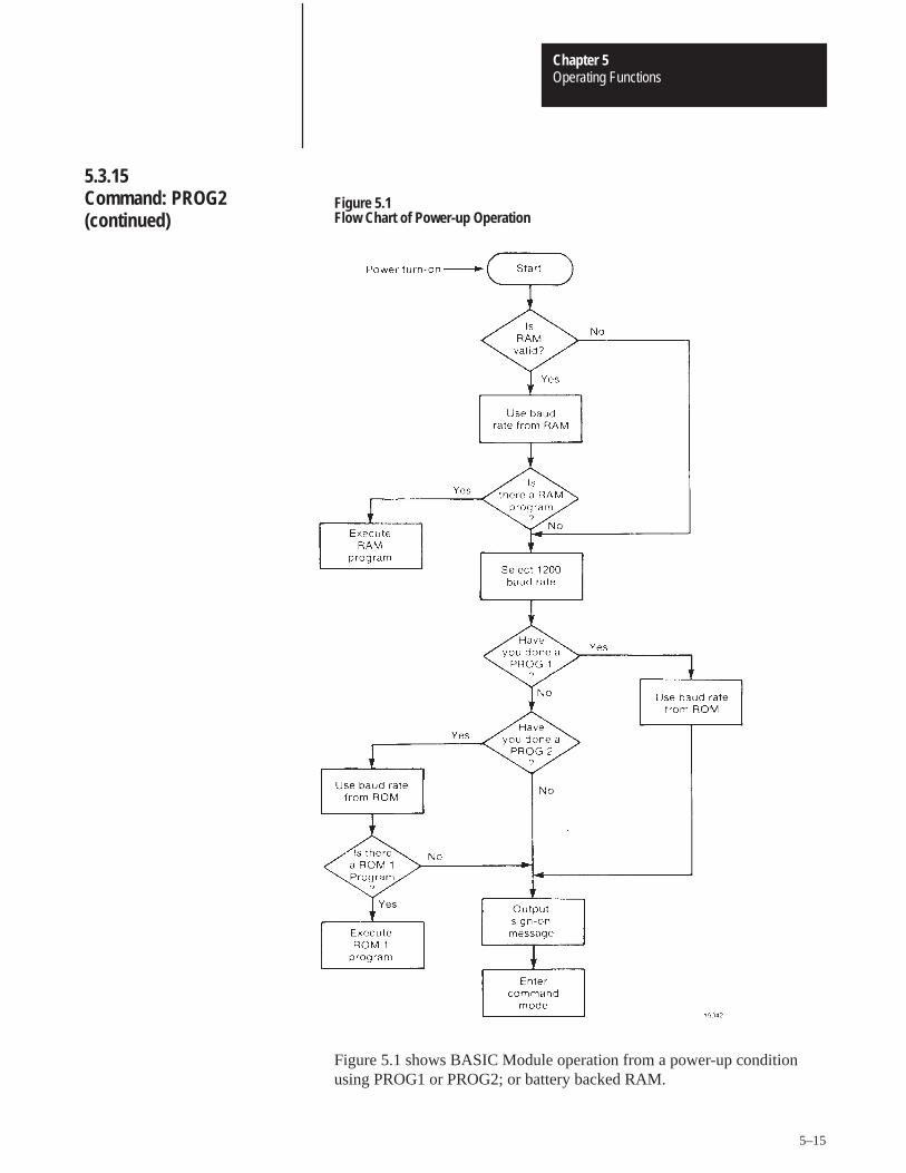
Operating FunctionsChapter 5
5–15
Figure 5.1Flow Chart of Power-up Operation
Figure 5.1 shows BASIC Module operation from a power-up conditionusing PROG1 or PROG2; or battery backed RAM.
5.3.15Command: PROG2(continued)
Operating FunctionsChapter 5
5–16
The�following sections list and describe the statements�you can�usewith the BASIC Module.
Mode:�COMMAND AND/ OR RUN Type:�CONTROL
You�use the CALL [integer] statement to call specially�written BASICModule application programs. Specific�call numbers are�defined laterin this chapter.
Mode:�COMMAND AND/OR RUN Type:�CONTROL
The�CLEAR statement�sets all variables equal to 0 and resets allBASIC�evoked interrupts and stacks. This means that after�the CLEARstatement is executed an ONTIME statement�must be executed before themodule acknowledges the�internal timer interrupts. ERROR trappingusing the ONE�RR statement also does not occur�until anONERR[integer]�statement is executed. The CLEAR statement�doesnot affect�the real time clock�that is enabled by�the�CLOCK1statement.�CLEAR also does not reset the memory that has beenallocated�for strings,�so it is not necessary�to enter�the STRING[expr],�[expr] statement�to re-allocate�memory for strings after theCLEAR�statement�is executed. In general,�CLEAR is used�to“erase”�all variables.
Mode:�COMMAND AND/OR RUN Type:�CONTROL
The�CLEARI statement clears all of the BASIC evoked interrupts.�TheONTIME interrupt�disables after the CLEARI statement�executes.CLEARI does not affect�the real time clock�enabled�by the CLOCK1statement. You can use this statement�to selectively�DISABLEONTIME interrupts during specific�sections of your BASIC�program.You must�execute the�ONTIME statement again before the specificinterrupts enable.
Important: When the CLEARI�statement is LISTED it appears�asCLEAR�I.
5.4Description of Statements
5.4.1Statement: CALL [integer]
5.4.2Statement: CLEAR
5.4.3Statement: CLEARI(clear interrupts)
Operating FunctionsChapter 5
5–17
Mode:�COMMAND/RUNType: CONTROL
The CLEARS statement resets�all of the module’s�stacks.�Thecontrol,�argument and internal�stacks all reset to their initializationvalues. You can use this�command to reset the stack if an error�occursin a subroutine.
Important: When the�CLEARS statement is LISTed it appears asCLEAR S.
Mode: COMMAND AND/OR�RUN Type: CONTROL
CLOCK1
The CLOCK1 statement enables the real time clock�feature�residenton the BASIC Module.�The special�function operator TIME isincremented�once every�5 milliseconds after the CLOCK1 statement isexecuted. The CLOCK1 STATEMENT uses an internal TIMER togenerate an interrupt once every 5 milliseconds.�Because of this, thespecial�function operator TIME has a resolution�of 5 milliseconds.The special�function operator�TIME counts�from 0 to 65535.995seconds.�After reaching�a count of 65535.995 seconds�TIMEoverflows�back to a count of zero. The interrupts associated�with theCLOCK1 statement�cause the module programs to�run at about 99.6%of normal speed.�That means that the interrupt handling for�the REALTIME�CLOCK feature uses about .4% of�the total CPU time.
CLOCK0
The CLOCK0 (zero)�statement�disables�or “turns�off” the real timeclock feature. After CLOCK0 is executed,�the special function operatorTIME no longer�increments. CLOCK0 is�the only�module statementthat can disable the real time clock. CLEAR and�CLEARI do NOTdisable the real time clock, only�its associated ONTIME interrupt.
Important: CLOCK1 and CLOCK0 are independent of the�wallclock.
5.4.4Statement: CLEARS
5.4.5Statements: CLOCK1and CLOCK0
Operating FunctionsChapter 5
5–18
Mode: RUNType: Assignment
DATA
DATA specifies expressions that you can retrieve using a READ statement.If multiple expressions per line are used, you MUST separate them with acomma.
Example:
�10�DATA 10,ASC(A), ASC(B), 35.627
Important: You cannot�use the CHR() operator�in a DATA statement.
READ
READ retrieves the expressions�that are specified in the DATA statementand assigns�the value of the expression to the variable in the READstatement.�The READ statement is�always followed�by one or morevariables. If more than one variable�follows�a READ statement, theyare separated by a comma.
RESTORE
RESTORE “resets”�the internal read pointer�to the beginning of thedata so that it may be read again.
Example:
�10 FOR I=1 TO 3 �20 READ A,B �30 PRINT A,B �40 NEXT I �50 RESTORE �60 READ A,B �70 PRINT A,B �80 DATA 10,20,�10/2,20/2,SIN(PI),COS(PI) �RUN
10 20 5 10 0 –1
10 20
Every time�a READ statement�is encountered the next consecutiveexpression�in the DATA statement�is evaluated and assigned�to thevariable in the READ statement.�You can place DATA statementsanywhere within a program.�They are not executed�and do not cause anerror. DATA statements are considered to be chained�together and appearto be one large DATA statement. If at anytime all the data is read andanother READ statement is executed,�the program terminates and themessage ERROR: NO�DATA�– IN LINE XX�prints to the consoledevice.
5.4.6Statements: DATA – READ – RESTORE
Operating FunctionsChapter 5
5–19
Mode:�COMMAND�AND/OR RUN Type:�Assignment
DIM reserves storage for matrices. The storage�area is first assumed�tobe zero.�Matrices�in the BASIC Module�may have only�onedimension and the size�of the dimensioned�array may not�exceed 254elements. Once a variable is dimensioned in�a program it may not bere-dimensioned.�An attempt to re-dimension�an array causes anARRAY SIZE�ERROR. If an arrayed�variable is used that is notdimensioned by the DIM statement,�BASIC assigns a default�value of10 to the array size. All arrays are set equal�to zero�when the RUNcommand, NEW command�or the�CLEAR�statement is executed. Thenumber of bytes allocated�for an array is 6 times�the array size�plus 1.The array�A(100) requires�606 bytes of storage. Memory�size usuallylimits the size of a dimensioned�array.
Variations: More than one variable�can be dimensioned�by a singleDIM statement.
Example:
�10 DIM A(25), B(15), A1(20)
Example: Default error on attempt to re-dimension�array
�10 A(5)10 –BASIC ASSIGNS DEFAULT OF 10 TO ARRAY SIZE HERE�20 DIM A(5) –ARRAY CANNOT BE RE–DIMENSIONED�RUN
ERROR: ARRAY SIZE – IN LINE�20
20 DIM�A(5)
- X
Mode:�RUNType:�CONTROL
The DO – UNTIL�[rel expr] instruction provides a means of “loopcontrol”�within a module�program.�All statements between�the DOand�the UNTIL [rel expr]�are executed until the relational�expressionfollowing the UNTIL statement is TRUE.�You may nest�DO – UNTILloops.
5.4.7Statement: DIM
5.4.8Statements: DO – UNTIL[rel expr]
Operating FunctionsChapter 5
5–20
Examples:
SIMPLE DO-UNTIL
�10 A=0�20 DO�30 A=A+1
�40 PRINT A�50 UNTIL A=4�60 PRINT “DONE”�70 END�RUN
1234
DONE
READY�
NESTED DO-UNTIL
�10 DO�20 A=A+1�30 DO�40 B=B+1�50 PRINT A,B,A,*B�60 UNTIL B=3�70 B=0�80 UNTIL A=3�90 END�RUN
1 1 11 2 21 3 32 1 22 2 42 3 63 1 33 2 63 3 9
READY�
5.4.8Statements: DO – UNTIL[rel expr] (continued)
Operating FunctionsChapter 5
5–21
Mode: RUN Type: CONTROL
The�DO – WHILE [rel expr] instruction�provides a means of “loopcontrol” within a module program. The operation of this statement issimilar to the DO –�UNTIL [rel expr] except that all�statementsbetween�the DO and the�WHILE [rel expr] are executed as long as therelational�expression following the WHILE statement�is true. You cannest�DO – WHILE and DO –�UNTIL statements.
Examples:
SIMPLE DO-WHILE NESTEDDO-WHILE - DO-UNTIL
�10 DO �10 DO�20 A=A+1 �20 PRINT A=A+1�30 PRINT A �25 DO�40 WHILE At4 �30 B=B+1�50 PRINT “DONE” �40 A,B,A*B�60 END �50 WHILE B��3�RUN �60 B=0
�70 UNTIL A=3�80 END�RUN
1 1 1 12 1 2 23 1 3 34 2 1 2DONE 2 2 4
2 3 6READY 3 1 3� 3 2 6
3 3 9
READY�
5.4.9Statements: DO – WHILE[rel expr] (continued)
Operating FunctionsChapter 5
5–22
Mode: RUN Type: CONTROL
The END statement�terminates program execution.�The continue command, CONT does�not operate�if the END statement�is used toterminate execution. A CAN’T CONTINUE ERROR prints to the console.The last statement in a module program�automatically terminatesprogram execution�if you do not use an end statement.�You shouldalways�use an END statement�to terminate a program.
Examples:
END STATEMENT TERMINATION
�10 FOR I=1 TO 4 �20 GOSUB 100 �30 NEXT I �40 END �100 PRINT�I �110 RETURN �RUN
12 3 4
READY �
Variations:�None
Mode: RUN Type: CONTROL
Use the�FOR – TO – (STEP) – NEXT statements�to set up and controlloops.
Example:
�5 B=0:�C=10 : D=2 �10 FOR A=�B TO C STEP D �20 PRINT�A �30 NEXT A �40 END
5.4.10Statement: END
5.4.11Statements: FOR – TO –(STEP) – NEXT
Operating FunctionsChapter 5
5–23
Since B=0, C=10 and D=2,�the PRINT statement�at line�20 executes6 times. The values of “A” printed are 0, 2, 4, 6, 8 and 10. “A” representsthe name of�the index or loop counter. The value of “B” is the startingvalue of the index. The value�of “C” is the limit�value of the index andthe�value of “D” is the increment�to the index. If the STEP statementand the value “D” are omitted,�the increment�value�defaults�to 1,therefore, STEP is an optional statement.�The NEXT statement�addsthe value of “D” to the index.�The index is then compared to the value of“C”, the limit.�If the index is less than or equal to the limit, controltransfers�back to the statement�after�the FOR statement.�Stepping“backwards”�(FOR�I= 100 TO 1 STEP–1) is�permitted in the BASICModule. You may not�omit the index from the�NEXT statement in themodule (The NEXT statement�is always followed by the appropriatevariable). You may nest FOR-NEXT loops up to 9 times.
Examples:
�10 FOR I=1 TO 4 �10 FOR I=O TO 8 STEP 2�20 PRINT I, �20 PRINT I�30 NEXT I �30 NEXT I�40 END �40 END�RUN �RUN
1 2 3 4 02468
READY� READY
�
Mode: RUN Type: CONTROL
GOSUB
The GO SUB [ln�num] statement�causes�the BASIC Module�totransfer�control of the program directly to the line number ([ln num])following the GOSUB statement.�In addition,�the GOSUB statementsaves the location�of the statement following�GOSUB on the controlstack so that you can perform a RETURN statement to return�control�tothe statement�following�the most recently�executed GO SUBSTATEMENT.
5.4.11Statements: FOR – TO –(STEP) – NEXT (continued)
5.4.12Statements: GOSUB[ln num] – RETURN
Operating FunctionsChapter 5
5–24
RETURN
Use this statement�to “return”�control to the statement following�themost recently executed GO SUB STATEMENT. Use one return for eachGOSUB to�avoid overflowing�the C-STACK. This�means that�asubroutine�called�by the GO SUB statement�can call anothersubroutine with another GOSUB statement.
Examples:
SIMPLE SUBROUTINE NESTED SUBROUTINES
�10 FOR I=1 TO 5 �10 FOR I=1 TO 3�20 GOSUB 100 �20 GOSUB 100�30 NEXT I �30 NEXT I�40 END �40 END�100 PRINT I �100 REM USER SUBROUTINE HERE�110 RETURN �105 PRINT I,�RUN �110 GOSUB 200
1 �200 PRINT I,I*I2 �210 RETURN3 �RUN4
5 1 12 4
READY 3 9�
READY�
Mode: COMMAND AND/OR�RUN Type: CONTROL
The GOTO [ln num] statement�causes BASIC to transfer control directlyto the line number ([ln�num]) following the GOTO statement.
Example:
�50 GOTO 100
If�line 100 exists,�this statement causes�execution�of the program toresume at line 100. If line number 100 does not exist the message ERROR:INVALID�LINE�NUMBER�is printed to the console device.
5.4.12Statements: GOSUB [ln num]– RETURN (continued)
5.4.13Statement: GOTO [ln num]
Operating FunctionsChapter 5
5–25
Unlike the RUN command the GOTO statement, if executed in theCOMMAND mode, does�not clear the variable storage space orinterrupts.�However, if�the GOTO statement is executed in theCOMMAND mode after a line�is edited the module clears�the variablestorage�space and all BASIC evoked interrupts. This is necessarybecause�the variable storage and the BASIC program reside in the sameRAM memory. Because�of this editing a program can destroy variables.
Mode: RUN Type:�CONTROL
The value�of the expression�following�the ON statement�is thenumber in the line list that control is transferred to.
Example:
�10 ON Q GOTO 100,200,300
If Q is equal to 0, control�is transferred�to line number 100.�If Q isequal to 1, control is transferred to line number 200. If Q is equal to 2,GOTO line 300, etc. All comments that apply to GOTO and�GOSUBapply�to the ON statement. If Q is less than�ZERO a BADARGUMENT ERROR�is�generated.�If Q is greater than the linenumber list�following�the GOTO or GOSUB statement, a BADSYNTAX�ERROR�is generated. The ON statement�provides“conditional branching”�options within the constructs of a BASICModule�program.
Mode: RUN Type:�CONTROL
The IF statement sets up a conditional test. The general form of the IF –THEN –�ELSE statement follows:
[ln num] IF [rel expr] THEN valid�statement�ELSE validstatement
Example:
�10 IF�A=100 THEN A=0 ELSE A=A+1
5.4.13Statement: GOTO [ln num](continued)
5.4.14Statements: ON [expr] GOTO[ln num], [ln num],...[ln num],ON [expr] GOSUB[ln num],[ln num],...[ln num]
5.4.15Statements: IF – THEN – ELSE
Operating FunctionsChapter 5
5–26
Upon execution�of line 10 IF A is�equal to 100, THEN A is assigned avalue of 0. IF A does not equal 100, A is�assigned a value of A+1. If youwant to�transfer�control to different line numbers using the IFstatement, you may omit�the GOTO statement.�The following examplesgive�the same results:
�20 IF�INT(A)��10 THEN GOTO�100�ELSE GOTO 200 or
�20 IF�INT(A)��10 THEN 100 ELSE 200
You can replace�the THEN statement�with any valid�BASIC Modulestatement, as shown below:
�30 IF�A�� 10 THEN PRINT�A�ELSE 10
�30 IF�A�� 10 PRINT�A�ELSE 10
You may execute�multiple�statements following�the THEN or ELSEif�you use a colon to separate them.
Example:
�30 IF�A�� 10 THEN PRINT�A:GOTO�150�ELSE 10
�30 IF�A�� 10 PRINT�A:GOTO 150 ELSE 10
In these examples,�if�A does not equal 10 then both PRINT A andGOTO 150�are executed.�If A10, then control passes to 10.
You may omit the ELSE statement. If you omit the ELSE statement controlpasses to the next statement.
Example:
�20 IF�A10 THEN 40
�30 PRINT�A
In this example, if A equals�10 then control�passes to line number 40. IfA does not equal 10 line�number 30�is executed.
Mode: RUN Type:�INPUT/OUTPUT
The INPUT statement allows you to enter data from the console duringprogram�execution. You may assign data to one or more variables with asingle�input statement.�You must separate the variables�with acomma.
Example:
�INPUT A,B
5.4.15Statements: IF – THEN – ELSE (continued)
5.4.16Statement: INPUT
Operating FunctionsChapter 5
5–27
Causes a question�mark (?)�to print on the console device.�Thisprompts�you to input�two numbers separated�by a comma. If you donot enter�enough data, the module prints�TRY AGAIN on the consoledevice.
Example:
�10 INPUT A,B �20 PRINT A,B �RUN
?1
TRY AGAIN
?1,21 2
READY
You can�write the INPUT statement�so that�a descriptive prompt tellsyou what to�enter. The message to be printed�is placed in quotes afterthe INPUT statement.�If a comma appears�before the first variable onthe input list,�the question mark prompt�character is not displayed.
Examples:
�10 INPUT“ENTER A NUMBER” A �10 INPUT”ENTER A NUMBER–”,A�20 PRINT SQR(A) �20 PRINT SQR(A)�30 END �30 END�RUN �RUN
ENTER A NUMBER ENTER A NUMBER–100?100 1010
You can�also assign strings with an INPUT statement. Strings�arealways terminated with a carriage�return (cr). If more than one stringinput is requested�with a single INPUT statement, the module promptsyou�with�a question mark.
5.4.16Statement: INPUT(continued)
Operating FunctionsChapter 5
5–28
Examples:
�10 STRING 110,10 �10 STRING 110,10�20 INPUT “NAME:”,$(1) �20 INPUT “NAMES:”,$(1),$(2)�30 PRINT “HI”,$(1) �30 PRINT “HI”,$(1),“ AND “,$(2)�40 END �40 END�RUN �RUN
NAME: SUSAN NAMES: BILLHI SUSAN ?ANN
HI BILL AND ANN
READYREADY
You can assign�strings and variables with a single�INPUT statement.
Example:
�10 STRING 100,10 �20 INPUT“NAME(CR),�AGE – ”,$(1),A �30 PRINT “HELLO ”,$(1),“,�YOU ARE ”,A,“YEARS�OLD” �40 END �RUN
NAME(CR), AGE –�FRED?15HELLO FRED,�YOU�ARE�15�YEARS OLD
READY �
Mode: COMMAND AND/OR�RUN
This statement, along with CALL 77, allows you to save/retrievevariables�to/from a protected�area of memory. This protected�area isnot zeroed on power-up�or when the RUN command is issued. The LD@statement takes�the variable stored at address�[expr] and moves it�tothe top of the argument stack.�For more information on protectingvariables,�see section 5.11.6, “Protected Variable Storage�– CALL 77”.
5.4.16Statement: INPUT(continued)
5.4.17Statement: LD@ [expr]
Operating FunctionsChapter 5
5–29
Mode: COMMAND AND/OR�RUNType:�ASSIGNMENT
Use the�LET statement�to assign a variable to the value of anexpression.�The general�form of�LET is:
LET [var] = [expr]
Examples:
LET A =10*SIN(B)/100�or
LET A = A+1
Note that�the = sign�used in the LET statement�is not an equalityoperator. It is a “replacement” operator. The statement�should�be readA is�replaced by A plus one. The word LET is always optional,�(i.e.LET A =2 is the same as A�=2).
When LET is�omitted�the LET statement is called�an IMPLIEDLET. We use�the word LET to refer�to both the LET statement�andthe�IMPLIED LET statement.
Also use the LET statement to assign the string�variables:
LET $(1)=“THIS�IS A STRING” or
LET $(2)=$(1)
Before�you can assign strings you must execute the STRING [expr],[expr] statement or else a MEMORY ALLOCATION ERROR occurs.See the following�section�5.4.31 titled, “STRING”.
5.4.18Statement: LET
Operating FunctionsChapter 5
5–30
Mode: RUN Type:�CONTROL
The ONERR[ln num]�statement lets you handle�arithmetic errors, ifthey occur, during program execution.�Only ARITH. OVERFLOW,ARITH. UNDERFLOW,�DIVIDE BY ZERO and BAD ARGUMENTerrors�are “trapped”�by the ONE RR�statement.�All other errors arenot “trapped”.�If an arithmetic error�occurs after�the ONE RRstatement�is executed,�the module interpreter passes control to the linenumber following the ONERR[ln num] statement. You handle the errorcondition in a manner suitable to the particular�application. The ONERRcommand�does not trap�bad data�entered during an inputinstruction.�This yields�a “TRY AGAIN”�message�or “EXTRAIGNORED”�message.�See Chapter�9 for an explanation of errors.
With the�ONERR[ln num] statement,�you have the option ofdetermining what�type of error�occurred. Do this�by examiningexternal�memory location 257 (101H)�after the error�condition�istrapped.
The error codes are:
ERROR�CODE =10�– DIVIDE BY ZERO
ERROR�CODE =20�– ARITH. OVERFLOW
ERROR�CODE�=30 – ARITH. UNDERFLOW
ERROR CODE =40 – BAD ARGUMENT
You can examine this location�by using an XBY(257) statement.
Example:
PRINT XBY(257)
or
E XBY(257)
5.4.19Statement: ONERR[ln num)
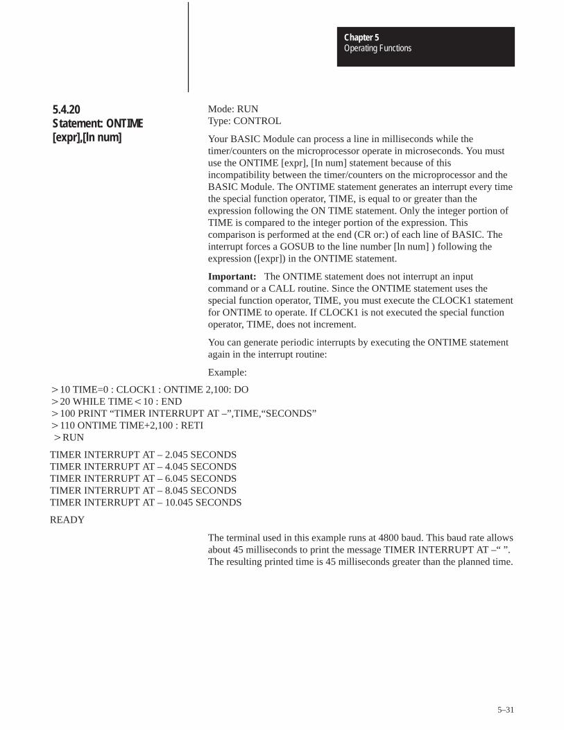
Operating FunctionsChapter 5
5–31
Mode: RUN Type: CONTROL
Your BASIC Module can process a line in milliseconds while thetimer/counters on the microprocessor operate in microseconds. You mustuse the ONTIME [expr], [In num] statement because of thisincompatibility between the timer/counters on the microprocessor and theBASIC Module. The ONTIME statement generates an interrupt every timethe special function operator, TIME, is equal to or greater than theexpression following the ON TIME statement. Only the integer portion ofTIME is compared to the integer portion of the expression. Thiscomparison is performed at the end (CR or:) of each line of BASIC. Theinterrupt forces a GOSUB to the line number [ln num] ) following theexpression ([expr]) in the ONTIME statement.
Important: The ONTIME statement does not interrupt an inputcommand or a CALL routine. Since the ONTIME statement uses thespecial function operator, TIME, you must execute the CLOCK1 statementfor ONTIME to operate. If CLOCK1 is not executed the special functionoperator, TIME, does not increment.
You can generate periodic interrupts by executing the ONTIME statementagain in the interrupt routine:
Example:
�10 TIME=0 : CLOCK1 : ONTIME 2,100: DO �20 WHILE TIME�10 : END�100 PRINT “TIMER INTERRUPT AT –”,TIME,“SECONDS” �110 ONTIME TIME+2,100 : RETI �RUN
TIMER INTERRUPT AT – 2.045 SECONDS TIMER INTERRUPT AT – 4.045 SECONDS TIMER INTERRUPT AT – 6.045 SECONDS TIMER INTERRUPT AT – 8.045 SECONDS TIMER INTERRUPT AT – 10.045 SECONDS
READY
The terminal used in this example runs at 4800 baud. This baud rate allowsabout 45 milliseconds to print the message TIMER INTERRUPT AT –“ ”.The resulting printed time is 45 milliseconds greater than the planned time.
5.4.20Statement: ONTIME[expr],[ln num]
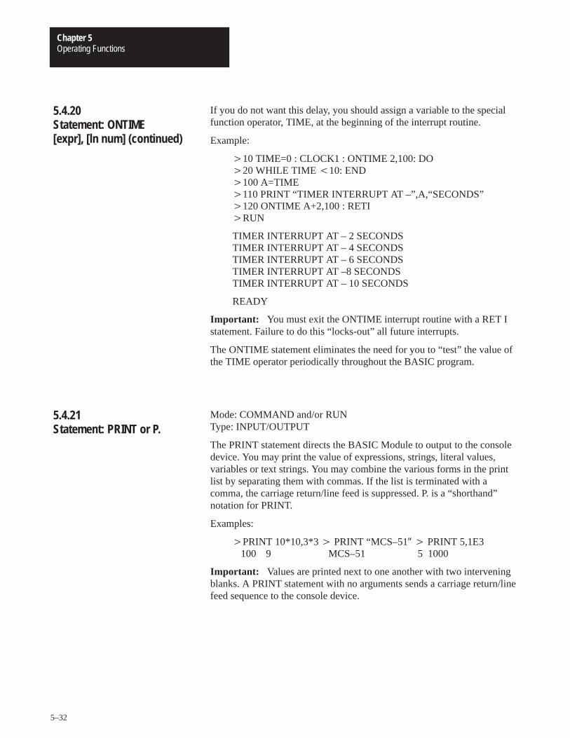
Operating FunctionsChapter 5
5–32
If you do not want this delay, you should assign a variable to the specialfunction operator, TIME, at the beginning of the interrupt routine.
Example:
�10 TIME=0 : CLOCK1 : ONTIME 2,100: DO �20 WHILE TIME �10: END�100 A=TIME �110 PRINT “TIMER INTERRUPT AT –”,A,“SECONDS” �120 ONTIME A+2,100 : RETI �RUN
TIMER INTERRUPT AT – 2 SECONDS TIMER INTERRUPT AT – 4 SECONDS TIMER INTERRUPT AT – 6 SECONDS TIMER INTERRUPT AT –8 SECONDS TIMER INTERRUPT AT – 10 SECONDS
READY
Important: You must exit the ONTIME interrupt routine with a RET Istatement. Failure to do this “locks-out” all future interrupts.
The ONTIME statement eliminates the need for you to “test” the value ofthe TIME operator periodically throughout the BASIC program.
Mode: COMMAND and/or RUN Type: INPUT/OUTPUT
The PRINT statement directs the BASIC Module to output to the consoledevice. You may print the value of expressions, strings, literal values,variables or text strings. You may combine the various forms in the printlist by separating them with commas. If the list is terminated with acomma, the carriage return/line feed is suppressed. P. is a “shorthand”notation for PRINT.
Examples:
�PRINT 10*10,3*3 � PRINT “MCS–51″ � PRINT 5,1E3100 9 MCS–51 5 1000
Important: Values are printed next to one another with two interveningblanks. A PRINT statement with no arguments sends a carriage return/linefeed sequence to the console device.
5.4.20Statement: ONTIME[expr], [ln num] (continued)
5.4.21Statement: PRINT or P.
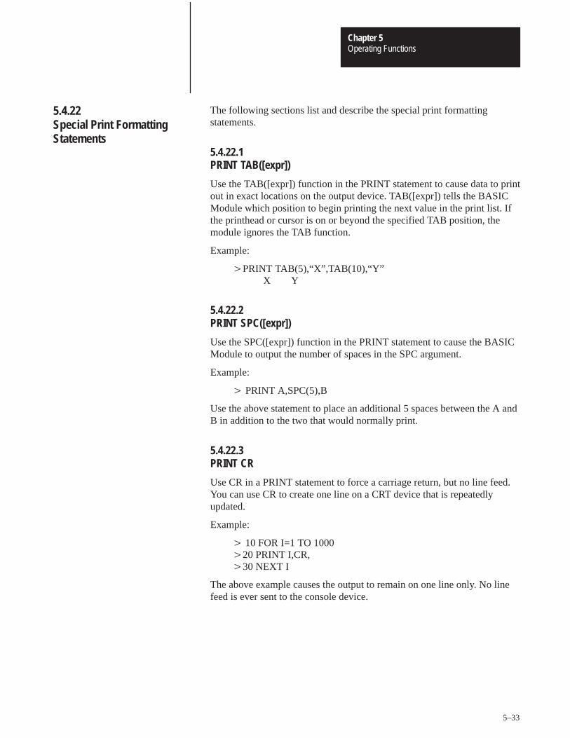
Operating FunctionsChapter 5
5–33
The following sections list and describe the special print formattingstatements.
5.4.22.1 PRINT TAB([expr])
Use the TAB([expr]) function in the PRINT statement to cause data to printout in exact locations on the output device. TAB([expr]) tells the BASICModule which position to begin printing the next value in the print list. Ifthe printhead or cursor is on or beyond the specified TAB position, themodule ignores the TAB function.
Example:
�PRINT TAB(5),“X”,TAB(10),“Y” X Y
5.4.22.2 PRINT SPC([expr])
Use the SPC([expr]) function in the PRINT statement to cause the BASICModule to output the number of spaces in the SPC argument.
Example:
� PRINT A,SPC(5),B
Use the above statement to place an additional 5 spaces between the A andB in addition to the two that would normally print.
5.4.22.3 PRINT CR
Use CR in a PRINT statement to force a carriage return, but no line feed.You can use CR to create one line on a CRT device that is repeatedlyupdated.
Example:
� 10 FOR I=1 TO 1000 �20 PRINT I,CR, �30 NEXT I
The above example causes the output to remain on one line only. No linefeed is ever sent to the console device.
5.4.22Special Print FormattingStatements
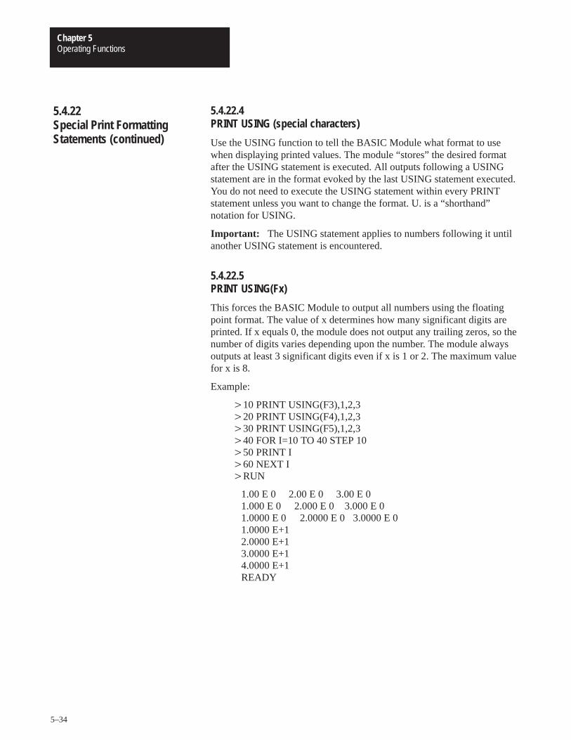
Operating FunctionsChapter 5
5–34
5.4.22.4 PRINT USING (special characters)
Use the USING function to tell the BASIC Module what format to usewhen displaying printed values. The module “stores” the desired formatafter the USING statement is executed. All outputs following a USINGstatement are in the format evoked by the last USING statement executed.You do not need to execute the USING statement within every PRINTstatement unless you want to change the format. U. is a “shorthand”notation for USING.
Important: The USING statement applies to numbers following it untilanother USING statement is encountered.
5.4.22.5 PRINT USING(Fx)
This forces the BASIC Module to output all numbers using the floatingpoint format. The value of x determines how many significant digits areprinted. If x equals 0, the module does not output any trailing zeros, so thenumber of digits varies depending upon the number. The module alwaysoutputs at least 3 significant digits even if x is 1 or 2. The maximum valuefor x is 8.
Example:
�10 PRINT USING(F3),1,2,3�20 PRINT USING(F4),1,2,3�30 PRINT USING(F5),1,2,3�40 FOR I=10 TO 40 STEP 10�50 PRINT I�60 NEXT I�RUN
1.00 E 0 2.00 E 0 3.00 E 01.000 E 0 2.000 E 0 3.000 E 01.0000 E 0 2.0000 E 0 3.0000 E 01.0000 E+12.0000 E+13.0000 E+14.0000 E+1READY
5.4.22Special Print FormattingStatements (continued)
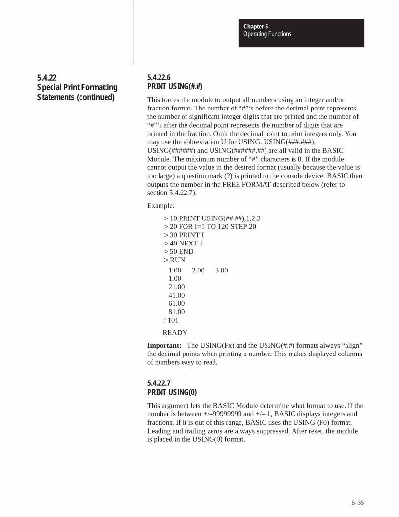
Operating FunctionsChapter 5
5–35
5.4.22.6 PRINT USING(#.#)
This forces the module to output all numbers using an integer and/orfraction format. The number of “#”’s before the decimal point representsthe number of significant integer digits that are printed and the number of“#”’s after the decimal point represents the number of digits that areprinted in the fraction. Omit the decimal point to print integers only. Youmay use the abbreviation U for USING. USING(###.###),USING(######) and USING(######.##) are all valid in the BASICModule. The maximum number of “#” characters is 8. If the modulecannot output the value in the desired format (usually because the value istoo large) a question mark (?) is printed to the console device. BASIC thenoutputs the number in the FREE FORMAT described below (refer tosection 5.4.22.7).
Example:
�10 PRINT USING(##.##),1,2,3 �20 FOR I=1 TO 120 STEP 20 �30 PRINT I �40 NEXT I �50 END �RUN
1.00 2.00 3.001.00 21.00 41.00 61.00 81.00
? 101
READY
Important: The USING(Fx) and the USING(#.#) formats always “align”the decimal points when printing a number. This makes displayed columnsof numbers easy to read.
5.4.22.7PRINT USlNG(0)
This argument lets the BASIC Module determine what format to use. If thenumber is between +/–99999999 and +/–.1, BASIC displays integers andfractions. If it is out of this range, BASIC uses the USING (F0) format.Leading and trailing zeros are always suppressed. After reset, the moduleis placed in the USING(0) format.
5.4.22Special Print FormattingStatements (continued)
Operating FunctionsChapter 5
5–36
5.4.22.8 Reset Print Head Pointer – CALL 99
You can use CALL 99 when printing out wide forms to reset the internalprint read/character counter and prevent the automatic CR/LF at character79. You must keep track of the characters in each line.
You can solve this problem in revision A or B modules using DBY(1 6H) 0
Example:
�10 REM THIS PRINTS TIME BEYOND 80TH COLUMN �20 PRINT TAB (79), �30 CALL 99 40 PRINT TAB (41), “TIME –”, �50 PRINT H , “:” , M , “:” ,S �60 GOTO 20 �70 END
Mode: COMMAND and/or RUN Type: INPUT/OUTPUT
The PRINT# (PRINT @) or P.# statement functions the same as thePRINT or P. statement except that the output is directed to the list deviceinstead of the console device. The baud rate and peripheral port parametersmust match your device. See Chapter 3 Section 3.2.4 titled, “ConfigurationPlugs” and Chapter 5 Section 5.8.1 titled, “Peripheral Port Support –Parameter Set – CALL 30″.
All comments that apply to the PRINT or P. statement apply to thePRINT# or P.# statement. P.# is a “shorthand” notation for PRINT#.
5.4.22Special Print FormattingStatements (continued)
5.4.23Statement: PRINT# or P.#
Operating FunctionsChapter 5
5–37
Mode: COMMAND and/or RUN Type: INPUT/OUTPUT
The PH0. and PH1. statements function the same as the PRINT statementexcept that the values are printed out in a hexadecimal format. The PH0.statement suppresses two leading zeros if the number printed is less than255 (0FFH). The PH1. statement always prints out four hexadecimal digits.The character “H” is always printed after the number when PH0. or PH1. isused to direct an output. The values printed are always truncated integers.If the number printed is not within the range of valid integer (i.e. between0 and 65535 (0FFFFH) inclusive), the BASIC Module defaults to thenormal mode of print. If this happens no “H” prints out after the value.Since integers are entered in either decimal or hexadecimal form thestatements PRINT, PH0., and PH1. are used to perform decimal tohexadecimal and hexadecimal to decimal conversion. All comments thatapply to the PRINT statement apply to the PH0. and PH1. statements.PH0.# and PH 1.# function the same as PH0. and PH1. respectively, exceptthat the output is directed to the list device instead of the console device.The baud rate and peripheral port parameters must match your device. SeeChapter 3 Section 3.2.4 titled, “Configuration Plugs” and Chapter 5Section 5.8.1 titled, “Peripheral Port Support – Parameter Set – CALL 30″.
Examples:
�PH0.2*2 �PH1.2*2 �PRINT 99 H �PH0.100
04H 0004H 153 64H
�PH0. 1000 �PH1. 1000 �P. 3E8H �PH0.PI
3E8H 03E8H 1000 03H
5.4.24Statements: PH0., PH1.,PH0.#, PH1.#
Operating FunctionsChapter 5
5–38
Mode: COMMAND AND/OR RUN Type: ASSIGNMENT
The arithmetic expression, or expressions, following the PUSH statementare evaluated and then placed in sequence on the BASIC Module’sARGUMENT STACK. This statement, in conjunction with the POPstatement, provides a simple means of passing parameters to assemblylanguage routines. In addition, the PUSH and POP statements are used topass parameters to BASIC subroutines and to “SWAP” variables. The lastvalue PUSHed onto the ARGUMENT STACK is the first value POPed offthe ARGUMENT STACK.
Variations: You can push more than one expression onto the ARGUMENTstack with a single PUSH statement. The expressions are followed by acomma: PUSH[expr],[expr],......... [expr]. The last value PUSHed onto theARGUMENT STACK is the last expression [expr] encountered in thePUSH STATEMENT.
Examples:
SWAPPING CALLVARIABLES ROUTINE�10 A=10 �10 PUSH 3�20 B=20 �20 CALL 10�30 PRINT A,B �30 POP W�40 PUSH A,B �40 REM PUSH VALUE ON STACK, CALL�50 POP A,B �50 REM CONVERSION, POP RESULT IN W�60 PRINT A,B �60 END�70 END�RUN
10 2020 10READY�
5.4.25Statement: PUSH[expr]
Operating FunctionsChapter 5
5–39
Mode: COMMAND AND/OR RUNTYPE: ASSIGNMENT
The value on top of the ARGUMENT STACK is assigned to the variablefollowing the POP statement and the ARGUMENT STACK is “POPed”(i.e. incremented by 6). You can place values on the stack using either thePUSH statement or assembly language CALLS.
Important: If a POP statement executes and no number is on theARGUMENT STACK, an A-STACK ERROR occurs.
Variations: You can pop more than one variable off the ARGUMENT stackwith a single POP statement. The variables are followed by a comma (i.e.POP [var],[var], ............ [var]).
Examples:
See PUSH statement above (section 5.4.25).
You can use the PUSH and POP statements to minimize GLOBAL variableproblems. These are caused by the “main” program and all subroutinesused by the main program using the same variable names (i.e. GLOBALVARIABLES). If you cannot use the same variables in a subroutine as inthe main program you can re–assign a number of variables (i.e. A=Q)before a GOSUB statement is executed. If you reserve some variablenames just for subroutines (S1, S2) and pass variables on the stack asshown in the previous example, you can avoid any GLOBAL variableproblems in the BASIC Module.
The PUSH and POP statements accept dimensioned variables A(4) andS1(12) as well as scalar variables. This is useful when large amounts ofdata must be PUSHed or POPed when using CALL routines.
Example:
�40 FOR I=1 TO 64 �50 PUSH I�60 CALL 10 �70 POP A(I) �80 NEXT I
5.4.26Statement: POP[var]
Operating FunctionsChapter 5
5–40
Mode: COMMAND and/or RUN Type: CONTROL – Performs no operation
REM is short for REMark. REM allows you to add comments to a programto make it easier to understand. If a REM statement appears on a line theentire line is used for the REM statement. You cannot terminate a REMstatement using a colon (:), however, you can place a REM statement aftera colon. This allows you to place a comment on each line.
Example:
�10 REM INPUT ONE VARIABLE �20 INPUT A �30 REM INPUT ANOTHER VARIABLE �40 INPUT B�50 REM MULTIPLY THE TWO �60 Z=A*B �70 REM PRINT THE ANSWER �80 PRINT Z �90 END �10 INPUT A: REM INPUT ONE VARIABLE �20 INPUT B : REM INPUT ANOTHER VARIABLE �30 Z=A*B : REM MULTIPLY THE TWO �40 PRINT Z :REM PRINT THE ANSWER �50 END
The following example does NOT work because the entire line isinterpreted as a REMark. The PRINT statement is not executed:
Example:
�10 REM PRINT THE NUMBER: PRINT A
Important: REMark statements add time to program execution. Usethem selectively or place them at the end of the program where they do notaffect program execution speed. Do not use REMark statements infrequently called loops or subroutines.
5.4.27Statement: REM
Operating FunctionsChapter 5
5–41
Mode: RUN Type: CONTROL
Use the RETI statement to exit from the ONTIME interrupts that arehandled by a BASIC Module program. The RETI statement functions thesame as the RETURN statement except that it also clears a softwareinterrupt flag so interrupts can again be acknowledged. If you fail toexecute the RETI statement in the interrupt procedure, all future interruptsare ignored.
Mode: COMMAND AND/OR RUN
This statement, along with CALL 77, allows you to save/retrieve variablesto/from a protected area of memory. This protected area is not zeroed onpower-up or when the RUN command is issued. The ST@ statement takesthe argument on top of the argument stack and moves it to the addresslocation specified by [expr]. For more information on protecting variables,see section 5.11.6, “Protected Variable Storage – CALL 77”.
Mode: RUN Type: CONTROL
The STOP statement allows you to break program execution at specificpoints in a program. After a program is STOPped you can display ormodify variables. You can resume program execution with a CONTinuecommand. The purpose of the STOP statement is to allow for easyprogram “debugging” More details of the STOP-CONT sequence arecovered in Section 5.3.2 titled, “Command: CONT”.
Example:
�10 FOR I=1 TO 100 �20 PRINT I �30 STOP �40 NEXT I �RUN
1STOP – IN LINE 40
READY �CONT
2
5.4.28Statement: RETI
5.4.19Statement: ST@ [expr]
5.4.30Statement: STOP
Operating FunctionsChapter 5
5–42
Note that the line number printed out after execution of the STOPstatement, is the line number following the STOP statement, not the linenumber that contains the STOP statement.
Mode: COMMAND and/or RUNType: CONTROL
The STRING [expr], [expr] statement allocates memory for strings.Initially, no memory is allocated for strings. If you attempt to define astring with a statement such as LET $(1)“HELLO” before memory isallocated for strings, a MEMORY ALLOCATION ERROR is generated.The first expression in the STRING [expr],[expr] statement is the totalnumber of bytes you want to allocate for string storage. The secondexpression gives the maximum number of bytes in each string. These twonumbers determine the total number of defined string variables.
The BASIC Module requires one additional byte for each string, plus oneadditional byte overall. The additional character for each string is allocatedfor the carriage return character that terminates the string. This means thatthe statement STRING 100,10 allocates enough memory for 9 stringvariables, ranging from $(0) to $(8) and all of the 100 allocated bytes areused. Note that $(0) is a valid string in the BASIC Module. Refer to thefollowing Section 5.10 titled, “Description of String Operators” for furtherdiscussion of strings and example programs for string memory allocation.
Important: After memory is allocated for string storage, commands (e.g.NEW) and statements (e.g. CLEAR) cannot “de-allocate” this memory.Cycling power also cannot de-allocate this memory unless battery backupis disabled. You can de-allocate memory by executing a STRING 0,0statement. STRING 0,0 allocates no memory to string variables.
Important: The BASIC Module executes the equivalent of a CLEARstatement every time the STRING [expr],[expr] statement executes. This isnecessary because string variables and numeric variables occupy the sameexternal memory space. After the STRING statement executes, allvariables are “wiped-out”. Because of this, you should perform stringmemory allocation early in a program (during the first statement ifpossible). If you re-allocate string memory you destroy all definedvariables.
5.4.30Statement: STOP(continued)
5.4.31Statement: STRING
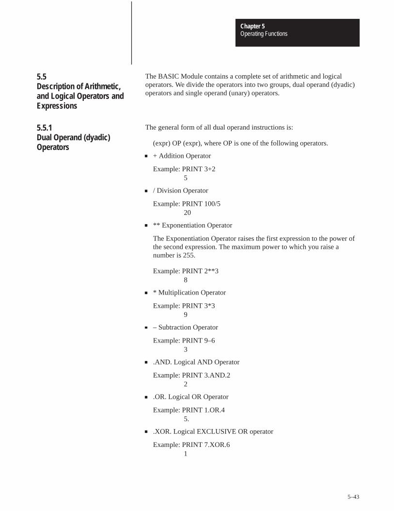
Operating FunctionsChapter 5
5–43
The BASIC Module contains a complete set of arithmetic and logicaloperators. We divide the operators into two groups, dual operand (dyadic)operators and single operand (unary) operators.
The general form of all dual operand instructions is:
(expr) OP (expr), where OP is one of the following operators.
+ Addition Operator
Example: PRINT 3+25
/ Division Operator
Example: PRINT 100/520
** Exponentiation Operator
The Exponentiation Operator raises the first expression to the power ofthe second expression. The maximum power to which you raise anumber is 255.
Example: PRINT 2**38
* Multiplication Operator
Example: PRINT 3*39
– Subtraction Operator
Example: PRINT 9–63
.AND. Logical AND Operator
Example: PRINT 3.AND.22
.OR. Logical OR Operator
Example: PRINT 1.OR.45.
.XOR. Logical EXCLUSIVE OR operator
Example: PRINT 7.XOR.61
5.5Description of Arithmetic,and Logical Operators andExpressions
5.5.1Dual Operand (dyadic)Operators
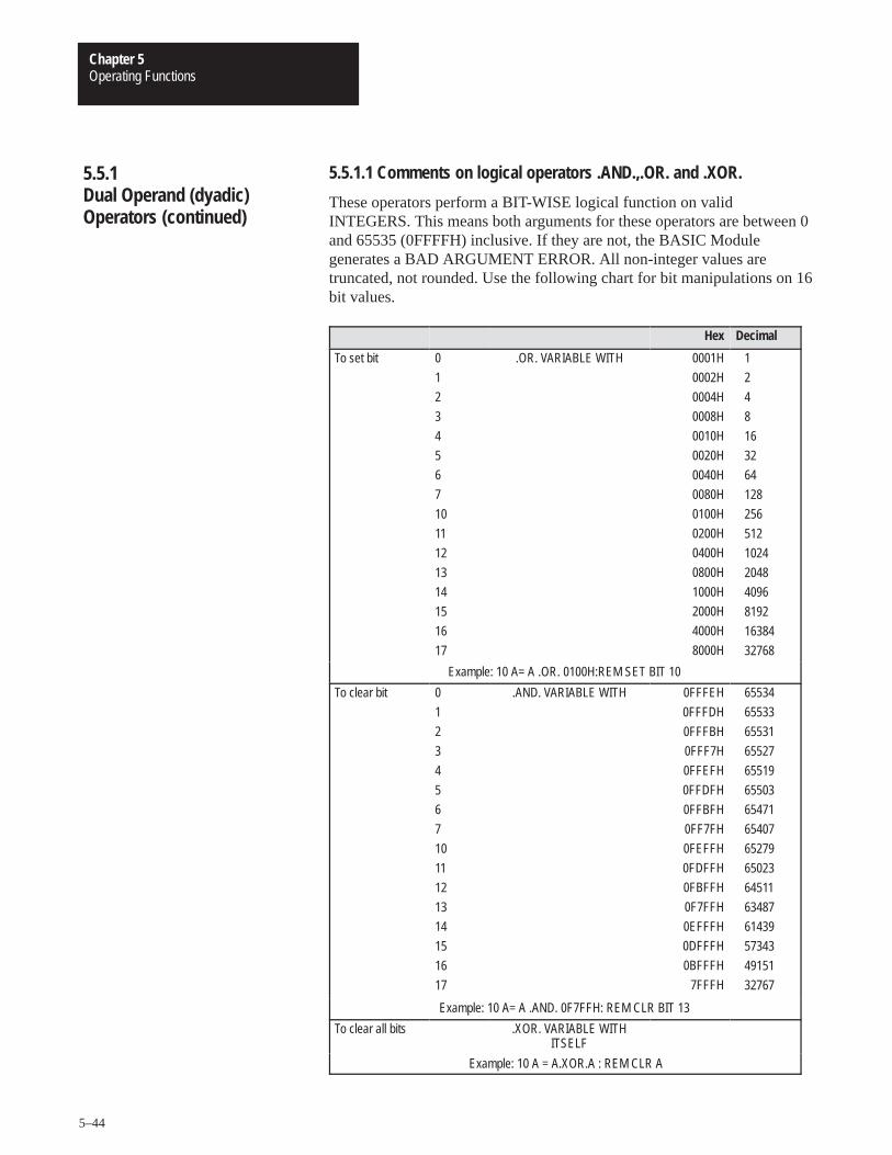
Operating FunctionsChapter 5
5–44
5.5.1.1 Comments on logical operators .AND.,.OR. and .XOR.
These operators perform a BIT-WISE logical function on validINTEGERS. This means both arguments for these operators are between 0and 65535 (0FFFFH) inclusive. If they are not, the BASIC Modulegenerates a BAD ARGUMENT ERROR. All non-integer values aretruncated, not rounded. Use the following chart for bit manipulations on 16bit values.
Hex Decimal
To set bit 0
1
2
3
4
5
6
7
10
11
12
13
14
15
16
17
.OR. VARIABLE WITH 0001H
0002H
0004H
0008H
0010H
0020H
0040H
0080H
0100H
0200H
0400H
0800H
1000H
2000H
4000H
8000H
1
2
4
8
16
32
64
128
256
512
1024
2048
4096
8192
16384
32768
Example: 10 A= A .OR. 0100H:REM SET BIT 10
To clear bit 0
1
2
3
4
5
6
7
10
11
12
13
14
15
16
17
.AND. VARIABLE WITH 0FFFEH
0FFFDH
0FFFBH
0FFF7H
0FFEFH
0FFDFH
0FFBFH
0FF7FH
0FEFFH
0FDFFH
0FBFFH
0F7FFH
0EFFFH
0DFFFH
0BFFFH
7FFFH
65534
65533
65531
65527
65519
65503
65471
65407
65279
65023
64511
63487
61439
57343
49151
32767
Example: 10 A= A .AND. 0F7FFH: REM CLR BIT 13
To clear all bits .XOR. VARIABLE WITHITSELF
Example: 10 A = A.XOR.A : REM CLR A
5.5.1Dual Operand (dyadic)Operators (continued)
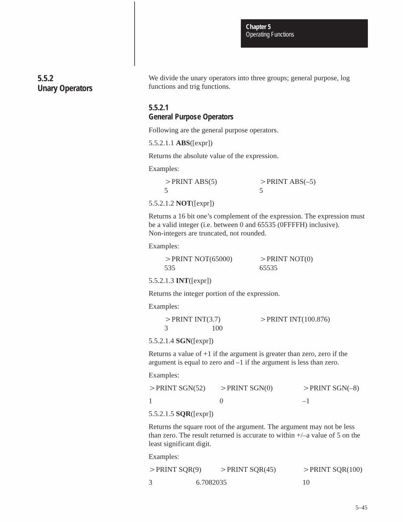
Operating FunctionsChapter 5
5–45
We divide the unary operators into three groups; general purpose, logfunctions and trig functions.
5.5.2.1 General Purpose Operators
Following are the general purpose operators.
5.5.2.1.1ABS([expr])
Returns the absolute value of the expression.
Examples:
�PRINT ABS(5) �PRINT ABS(–5)5 5
5.5.2.1.2NOT([expr])
Returns a 16 bit one’s complement of the expression. The expression mustbe a valid integer (i.e. between 0 and 65535 (0FFFFH) inclusive).Non-integers are truncated, not rounded.
Examples:
�PRINT NOT(65000) �PRINT NOT(0)535 65535
5.5.2.1.3INT ([expr])
Returns the integer portion of the expression.
Examples:
�PRINT INT(3.7) �PRINT INT(100.876)3 100
5.5.2.1.4SGN([expr])
Returns a value of +1 if the argument is greater than zero, zero if theargument is equal to zero and –1 if the argument is less than zero.
Examples:
�PRINT SGN(52) �PRINT SGN(0) �PRINT SGN(–8)
1 0 –1
5.5.2.1.5SQR([expr])
Returns the square root of the argument. The argument may not be lessthan zero. The result returned is accurate to within +/–a value of 5 on theleast significant digit.
Examples:
�PRINT SQR(9) �PRINT SQR(45) �PRINT SQR(100)
3 6.7082035 10
5.5.2Unary Operators
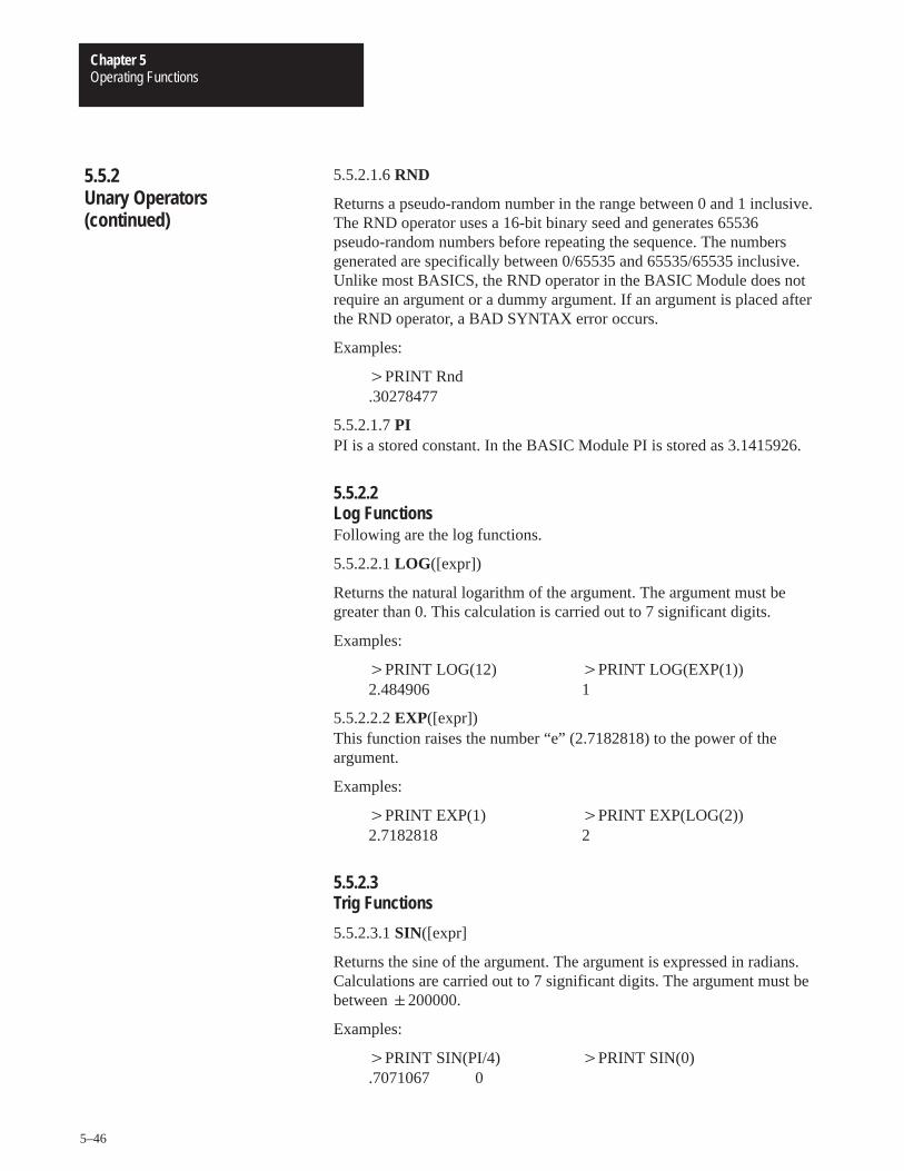
Operating FunctionsChapter 5
5–46
5.5.2.1.6RND
Returns a pseudo-random number in the range between 0 and 1 inclusive.The RND operator uses a 16-bit binary seed and generates 65536pseudo-random numbers before repeating the sequence. The numbersgenerated are specifically between 0/65535 and 65535/65535 inclusive.Unlike most BASICS, the RND operator in the BASIC Module does notrequire an argument or a dummy argument. If an argument is placed afterthe RND operator, a BAD SYNTAX error occurs.
Examples:
�PRINT Rnd.30278477
5.5.2.1.7PI PI is a stored constant. In the BASIC Module PI is stored as 3.1415926.
5.5.2.2 Log FunctionsFollowing are the log functions.
5.5.2.2.1LOG ([expr])
Returns the natural logarithm of the argument. The argument must begreater than 0. This calculation is carried out to 7 significant digits.
Examples:
�PRINT LOG(12) �PRINT LOG(EXP(1))2.484906 1
5.5.2.2.2EXP([expr])This function raises the number “e” (2.7182818) to the power of theargument.
Examples:
�PRINT EXP(1) �PRINT EXP(LOG(2))2.7182818 2
5.5.2.3 Trig Functions
5.5.2.3.1SIN([expr]
Returns the sine of the argument. The argument is expressed in radians.Calculations are carried out to 7 significant digits. The argument must bebetween�200000.
Examples:
�PRINT SIN(PI/4) �PRINT SIN(0).7071067 0
5.5.2Unary Operators(continued)
Operating FunctionsChapter 5
5–47
5.5.2.3.2COS([expr])
Returns the cosine of the argument. The argument is expressed in radians.Calculations are carried out to 7 significant digits. The argument must bebetween � 200000.
Examples:
�PRINT COS(PI/4) �PRINT COS(0) .7071067 1
5.5.2.3.3 TAN([expr])
Returns the tangent of the argument. The argument is expressed in radians.The argument must be between�200000.
Examples:
�PRINT TAN(PI/4) �PRINT TAN(0) 1 0
5.5.2.3.4 ATN([expr])
Returns the arctangent of the argument. The result is in radians.Calculations are carried out to 7 significant digits. The ATN operatorreturns a result between –PI/2 (3.1415926/2) and PI/2.
Examples:
�PRINT ATN(PI) �PRINT ATN(1)1.2626272 .78539804
5.5.2.4 Comments on Trig Functions
The SIN, COS and TAN operators use a Taylor series to calculate thefunction. These operators first reduce the argument to a value between 0and PI/2. This reduction is accomplished by the following equation:
reduced argument = (user arg/PI – INT(user arg/PI)) * PI
The reduced argument, from the above equation, is between 0 and PI. Thereduced argument is then tested to see if it is greater than PI/2. If it is, thenit is subtracted from PI to yield the final value. If it is not, then the reducedargument is the final value.
5.5.2Unary Operators(continued)
Operating FunctionsChapter 5
5–48
Although this method of angle reduction provides a simple and economicalmeans of generating the appropriate arguments for a Taylor series, there isan accuracy problem associated with this technique. The accuracy problemis noticed when the user argument is large (i.e. greater than 1000). This isbecause significant digits, in the decimal (fraction) portion of reducedargument are lost in the (user arg/PI – INT(user arg/PI)) expression. As ageneral rule, keep the arguments for the trigonometric functions as small aspossible.
You can write complex expressions using only a small number ofparenthesis. To illustrate the precedence of operators examine thefollowing equation:
4+3*2 =?
In this equation multiplication has precedence over addition.
Therefore, multiply (3*2) and then add 4.
4+3*2 = 10
When an expression is scanned from left to right an operation is notperformed until an operator of lower or equal precedence is encountered.In the example you cannot perform addition because multiplication hashigher precedence. Use parentheses if you are in doubt about the order ofprecedence. The precedence of operators from highest to lowest in theBASIC Module is:
1) Operators that use parenthesis ()
2) Exponentiation (**)
3) Negation (–)
4) Multiplication (*) and division (/)
5) Addition (+) and subtraction (–)
6) Relational expressions (=, �� , �, �=, �, �=).
7) Logical and (.AND.)
8) Logical or (.OR.)
9) Logical XOR (.XOR.)
5.5.2Unary Operators(continued)
5.5.3Understanding Precedenceof Operators
Operating FunctionsChapter 5
5–49
Relational expressions involve the operators =, ��, �, �=, �, and �=.These operators are typically used to “test” a condition. In the BASICModule relational operations are typically used to “test” a condition. In theBASIC Module relational operators return a result of 665535 (OFFFFH) ifthe relational expression is true, and a result of 0, if the relation expressionis false. The result is returned to the argument stack. Because of this, it ispossible to display the result of a relational expression.
Examples:
PRINT 1=0 PRINT 1�0 PRINT A �� A PRINT A=A
0 65535 0 65535
You can “chain” relational expressions together using the logical operators.AND., .OR., and .XOR.. This makes it possible to test a complexcondition with ONE statement.
Example:
�10 IF ([A�B].AND. [A�C]) .OR.[A�D] THEN
Additionally, you can use the NOT([expr]) operator.
Example:
�10 IF NOT(A�B).AND.(A�C) THEN
By “chaining” together relational expressions with logical operators, youcan test particular conditions with one statement.
Important: When using logical operators to link together relationalexpressions, you must be sure operations are performed in the propersequence.
5.5.4How Relational ExpressionsWork
Operating FunctionsChapter 5
5–50
Special operators include special function operators and system controlvalues.
Special function operators directly manipulate the I/O hardware and thememory addresses on the processor.
5.6.1.1 GET
Use the GET operator in the RUN mode. It returns a result of zero in thecommand mode. The GET operator reads the console input device. If acharacter is available from the console device, the value of the character isassigned to GET. After GET is read in the program, it is assigned the valueof zero until another character is sent from the console device. Thefollowing example prints the decimal representation of any character sentfrom the console:
Example:
�10 A=GET�20 IF A �� 0 THEN PRINT A :REM ZERO MEANS NO ENTRY �30 GOTO 10 �RUN
65 (TYPE “A” ON CONSOLE) 49 (TYPE “1” ON CONSOLE) 24 (TYPE “CONTROL–X” ON CONSOLE) 50 (TYPE “2” ON CONSOLE)
The GET operator is read only once before it is assigned a value of zero.This guarantees that the first character entered is always read, independentof where the GET operator is placed in the program. There is no bufferingof characters on the program port.
5.6.1.2 TIME
Use the TIME operator to retrieve and/or assign a value to the real timeclock resident in the BASIC Module. After reset, time is equal to 0. TheCLOCK1 statement enables the real time clock. When the real time clockis enabled, the special function operator, TIME, increments once every 5milliseconds. The units of time are in seconds.
5.6Special Operators
5.6.1Special Function Operators
Operating FunctionsChapter 5
5–51
When TIME is assigned a value with a LET statement (i.e. TIME� 100),only the integer portion of TIME is changed.
Example:
�CLOCK1 (enable REAL TIME CLOCK)
�CLOCK0 (disable REAL TIME CLOCK)
�PRINT TIME (display TIME) 3.315
�TIME = 0 (set TIME = 0)
�PRINT TIME (display TIME).315 (only the integer is changed)
You can change the “fraction” portion of TIME by manipulating thecontents of internal memory location 71 (47H). You can do this by using aDBY(71) statement. Note that each count in internal memory location 71(47H) represents 5 milliseconds of TIME.
Continuing with the example:
�DBY(71) = 0 (fraction of TIME = 0)
�PRINT TIME 0
�DBY(71) = 3 (fraction of TIME = 3, 15 ms)
�PRINT TIME 1.5 E–2
Only the integer portion of TIME changes when a value is assigned. Thisallows you to generate accurate time intervals. For example, if you want tocreate an accurate 12 hour clock: There are 43200 seconds in a 12 hourperiod, so an ONTIME 43200, (ln num) statement is used. When the TIMEinterrupt occurs, the statement TIME 0 is executed, but the millisecondcounter is not re-assigned a value. If interrupt latency exceeds 5milliseconds, the clock remains accurate.
5.6.1Special Function Operators(continued)
Operating FunctionsChapter 5
5–52
The system control values determine how memory is allocated by theBASIC Module.
5.6.2.1 MTOP
After reset, the BASIC Module sizes the external memory and assigns thelast valid memory address to the system control value, MTOP. The moduledoes not use any external RAM memory beyond the value assigned toMTOP.
Examples:
�PRINT MTOP or PH0. MTOP 14335 37FFH
5.6.2.2 LEN
The system control value, LEN, tells you how many bytes of memory thecurrently selected program occupies. This is the length of the program anddoes not include the size of string memory, variables and array memoryusage. You cannot assign LEN a value, it can only be read. A NULLprogram (i.e. no program) returns a LEN of 1. The 1 represents the end ofprogram file character.
Important: The BASIC Module does not require any “dummy”arguments for the system control values.
The BASIC Module communicates with the host processor usingblock-transfer communications. The host processor sends variable lengthblocks of data to the module. You can transfer a maximum of 64 words inand 64 words out per scan. The module responds with the requested blocklength of data. The module has an auxiliary processor dedicated toservicing of the block-transfers to and from the host processor. Thesesupport routines provide the communications link between the hostprocessor and the BASIC processor. The block-transfer-read (BTR) bufferresides at address 7800H and is 128 bytes long. You can examine thevalues in the buffer using the XBY command, i.e. PRINT XBY(7800H).
The block-transfer-write (BTW) buffer resides at one of two startingaddresses; 7B00H or 7C00H . Examine addresses 7D0 AH and 7D0BHwhich point to the proper starting address. 7D0AH contains the high byteof the address and 7D0BH contains the low byte of the address. The BTWbuffer is also 128 bytes long. You can also examine these values in thebuffer using the XBY command.
5.6.2System Control Values
5.7Data Transfer SupportRoutines
Operating FunctionsChapter 5
5–53
Example:
�10 REM PRINT CONTENTS OF BTW BUFFER �20 C=(XBY(7D0AH)*100H)+XBY(7D0BH) �30 FOR I=0 TO 128 �40 PH0. XBY(C+I), �50 NEXT I �60 END
This routine transfers the block-transfer-read (BTR) buffer to the auxiliaryprocessor on the BASIC Module for use in the next BTR request from thehost processor. If no data transfer occurs within 2 seconds the routinereturns to BASIC without transferring data. This routine has no inputarguments and one output argument (the status of the transfer). A non-zeroreturned means that no transfer occurred and the CALL timed out. A zeroreturned means a successful transfer.
Example:
�10 CALL 2 �20 POP X �30 IF X �� 0 PRINT “TRANSFER UNSUCCESSFUL”
This routine transfers the block-transfer-write (BTW) buffer of theauxiliary processor on the BASIC Module to the BASIC BTW buffer. If nodata transfer occurs within 2 seconds the routine returns to BASIC with nonew data. This routine has no input arguments and one output argument(the status of the transfer). A non-zero returned means that no transferoccurred and the CALL timed out. A zero returned means a successfultransfer.
Example:
�10 CALL 3 �20 POP X �30 IF X �� 0 PRINT “TRANSFER UNSUCCESSFUL”
5.7Data Transfer SupportRoutines (continued)
5.7.1Update Block-Transfer-ReadBuffer (timed) – CALL 2
5.7.2Update Block-Transfer-WriteBuffer (timed) – CALL 3
Operating FunctionsChapter 5
5–54
This routine sets the number of words (1–64) to transfer between theBASIC Module and the host processor. The processor programblock-transfer length must match the set value. Only one argument is input(the number of words to BTW) and none returned. If not used, the defaultlength is 5 words.
Example:
�10 PUSH 10: �20 CALL 4
This routine sets the number of words (1–64) to transfer between theBASIC Module and the host processor. The processor programblock-transfer length must match the set value. Only one argument is input(the number of words to BTR) and none returned. If not used, the defaultlength is 5 words.
Example:
�10 PUSH 10 �20 CALL 5
This routine transfers the block-transfer-write (BTW) buffer of theauxiliary processor on the BASIC Module to the BASIC BTW buffer. Thisroutine waits until a block-transfer occurs if one has not previouslyoccurred.
This routine transfers the block-transfer-read (BTR) buffer to the auxiliaryprocessor on the BASIC Module for use in the next BTR request from thehost processor. This routine waits until a block-transfer occurs.
Important: You must use an Interrupt Control CALL 8 before a PROGcommand to disable interrupts.
This routine disables system interrupts. It is mandatory for PROMprogramming. The wall clock cannot be accessed and the peripheral port isdisabled by this call. Some call routines enable interrupts automaticallyupon completion.
5.7.3Set Block-Transfer-WriteLength – CALL 4
5.7.4Set Block-Transfer-ReadLength – CALL 5
5.7.5Update Block-Transfer-WriteBuffer – CALL 6
5.7.6Update Block-Transfer-ReadBuffer – CALL 7
5.7.7Disable Interrupts – CALL 8
Operating FunctionsChapter 5
5–55
Important: You must use an Interrupt Control CALL 9 after a PROGcommand to re-enable interrupts.
This routine enables system interrupts. It is mandatory after programminga PROM. The wall clock is accessible and the peripheral port is enabled.
All of the input call conversion routines require the same sequence ofcommands. These are:
PUSH – the word position of the processor block-transfer-file to beconverted (1–64)
CALL – the appropriate input conversion
POP – the input argument into a variable
The data format of the output arguments from each of the input conversionroutines is described in more detail in Chapter 7.
5.7.9.1 3-Digit Signed, Fixed Decimal BCD to Internal Floating Point �XXX –CALL 10
The input argument is the number (1 to 64) of the word in thewrite-block-transfer buffer that is to be converted from 3-digit BCD tointernal format. The output argument is the converted value in internalfloating point format. The sign bit is bit number 16.
5.7.9.2 16-Bit Binary (4-digit hex) to Internal Floating Point – CALL 11
The input argument is the number (1 to 64) of the word in thewrite-data-transfer buffer to be converted from 16-bit binary to internalformat. The output argument is the converted value in internal floatingpoint format. There are no sign or error bits decoded.
5.7.9.3 4-Digit Signed Octal to Internal Floating Point �XXXX – CALL 12
The input argument is the number (1 to 64) of the word in the processorblock-transfer buffer to be converted from 4-digit signed octal to internalformat. This 12-bit format has a maximum value of �7777 octal. Theoutput argument is the converted value in internal floating point format.The sign bit is bit number 16.
5.7.8Enable Interrupts – CALL 9
5.7.9Input Call ConversionRoutines
Operating FunctionsChapter 5
5–56
5.7.9.4 6-Digit, Signed, Fixed Decimal BCD to Internal Floating Point�XXXXXX – CALL 13
The input argument is the number (1–64) of the first word (6-digit BCD issent to the BASIC module in two processor words) of thewrite-block-transfer buffer to be converted from 6-digit, signed, fixeddecimal BCD to internal format. The maximum values allowed are�999999. The output argument is the converted value in internal floatingpoint format. The sign bit is bit number 16.
5.7.9.5 4-Digit BCD to Internal Floating Point XXXX – CALL 17
The input argument is the number (1–64) of the word in thewrite-block-transfer buffer to be converted from 4-digit BCD to internalformat. The maximum value allowed is 0–9999. The output argument isthe converted value in internal floating point format.
Sample input conversions:
�20 PUSH 3 :REM CONVERT 3rd WORD OF PLC DATA �30 CALL 10 :REM DO 3 DIGIT BCD TO F.P. CONVERSION�40 POP W :REM GET CONVERTED VALUE – STORE IN VARIABLE W �20 PUSH 9 :REM CONVERT STARTING WITH 9th WORD OF PLC DATA �30 CALL 13 :REM DO 6 DIGIT BCD TO F.P. CONVERSION �40 POP L(9) :REM GET CONVERTED VALUE – STORE IN ARRAY L (9)
All of the output call conversion routines require the same sequence ofcommands. These are:
PUSH – the value to be converted
PUSH – the word position of the processor block-transfer-file to beconverted (1–64)
CALL – the appropriate output conversion
The data format of the converted value of each of the output conversionroutines is described in more detail in Chapter 7. Use these output callconversion routines to load the BTR buffer before executing a CALL 7 orCALL 2.
5.7.9Input Call ConversionRoutines (continued)
5.7.10Output Call ConversionRoutines
Operating FunctionsChapter 5
5–57
5.7.10.1 Internal Floating Point to 3-Digit, Signed, Fixed Decimal BCD �XXX –CALL 20
This routine has two input arguments and no output arguments. The firstargument is the variable with a value in the range of –999 to +999 that isconverted to a signed 3-digit binary coded decimal format used by theprocessor. The second input argument is the number of the word to receivethe value in the read-block-transfer buffer. The sign bit is bit number 16.
Example:
�20 PUSH W :REM DATA TO BE CONVERTED�30 PUSH 6 :REM WORD LOCATION TO GET DATA�40 CALL 20
5.7.10.2 Internal Floating Point to 16-Bit Unsigned Binary (4 digit hex) – CALL 21
This routine takes a value between 0 and 65535 and converts it to itsbinary representative and stores this in the read-block-transfer buffer in oneword. Two arguments are PUSHed and none POPed. The first valuePUSHed is the data or variable. This is followed by the number of theword to receive the value in the read-block-transfer buffer.
Example:
�50 PUSH T :REM THE VALUE TO CONVERTED TO 16 BINARY�60 PUSH 3 :REM WORD 3 IN THE BTR BUFFER GETS THE VALUE T�70 CALL 21 :REM DO THE CONVERSION
5.7.10.3Internal Floating Point to 4-Digit, Signed Octal �XXXX–Call 22
This routine converts a value from internal format to a four digit signedoctal value. Two arguments ar PUSHed and non POPed. The first valuePUSHed is the data (�77778) or variable. This is followed by the numberof the word to receive the value in the read-block-transfer buffer. The signbit is bit number 16.
Example:
�50 PUSH H :REM THE VALUE TO CONVERTED TO 4-DIGIT SIGNED OCTAL�60 PUSH 3 :REM WORD 3 IN THE BTR BUFFER GETS THE VALUE H�70 CALL 22 :REM DO THE CONVERSION
5.7.10Output Call ConversionRoutines (continued)
Operating FunctionsChapter 5
5–58
5.7.10.4 Internal Floating Point to 6-Digit, Signed, Fixed Decimal BCD�XXXXXX – CALL 23
This routine converts an internal 6-digit, signed, integer to a 2 word formatand places the converted value in the read-block-transfer buffer. Twoarguments are PUSHed and none POPed. The first value PUSHed is thedata or variable. This is followed by the number of the word to receive thevalue in the read-block-transfer buffer. The sign bit is bit number 16.
Example:
�20 PUSH 654321. OR �20 PUSH B(I) �30 PUSH 3 �30 PUSH 3 �40 CALL 23 �40 CALL 23
5.7.10.5 Internal Floating Point to 3.3-digit, Signed, Fixed Decimal BCD�XXX.XXX – CALL 26
This routine converts a variable in internal format to a signed, 6-digit,fixed decimal point number which is stored in 2 words in theblock-transfer-read buffer. Two arguments are PUSHed and none POPed.The first value PUSHed is the data (�999.999) or variable. This isfollowed by the number of the first word to receive the value in theblock-transfer-read buffer. The sign bit number is 16.
Example:
�50 PUSH S :REM THE VALUE TO BE CONVERTED TO 3.3-DIGIT FIXED POINT �60 PUSH 3 :REM WORD 3 IN THE BTR BUFFER GETS THE VALUES �70 CALL 26 :REM DO THE CONVERSION
5.7.10.6 Internal Floating Point to 4-digit BCD XXXX – CALL 27
This routine converts a value in internal floating point format to a 4-digit,unsigned BCD value and places it in the read-block-transfer buffer. Twoarguments are PUSHed and none POPed. The first value PUSHed is thedata (0–9999) or variable. This is followed by the number of the word toreceive the value in the read-block-transfer buffer.
Example:
�20 PUSH B REM THE VALUE TO BE CONVERTED TO 4-DIGIT BCD �30 PUSH 7 :REM WORD 7 IN THE BTR BUFFER GETS THE VALUE B �40 CALL 27 :REM DO THE CONVERSION
5.7.10Output Call ConversionRoutines (continued)
Operating FunctionsChapter 5
5–59
The peripheral port is used for:
1. exchanging data with an external device with user written protocol.
2. listing programs with the LIST# or LIST @ statement.
3. loading/saving programs using the 1771–SA/SB data recorders.
For these functions to operate properly and to allow flexibility for talkingto many different devices we provide parameter setup routines.
To make best use of the port, a 256 character buffer is provided on bothinput and output. This means that the module may receive up to 256characters without error from a device before the module must service thedata. The module can store an entire response to a command in the inputbuffer. This is useful when the data arrives in a high speed burst that is toofast for the BASIC program to handle character by character.
The 256 character output buffer allows the module to assemble an entiremessage leaving your user program free to perform other operations whilethe message is sent character by character by the device driver.
This routine sets up the parameters for the peripheral port. The parametersset are the number of bits/word, parity enable or disable, even or oddparity, number of stop bits, software handshaking and hardwarehandshaking. Default values are:
1 stop bit
no parity
8 bits/character
DCD off
XON/XOFF disabled
1200 baud (jumper selected)
1 start bit (fixed)
5.8Peripheral Port Support
5.8.1Peripheral Port Support –Parameter Set – CALL 30
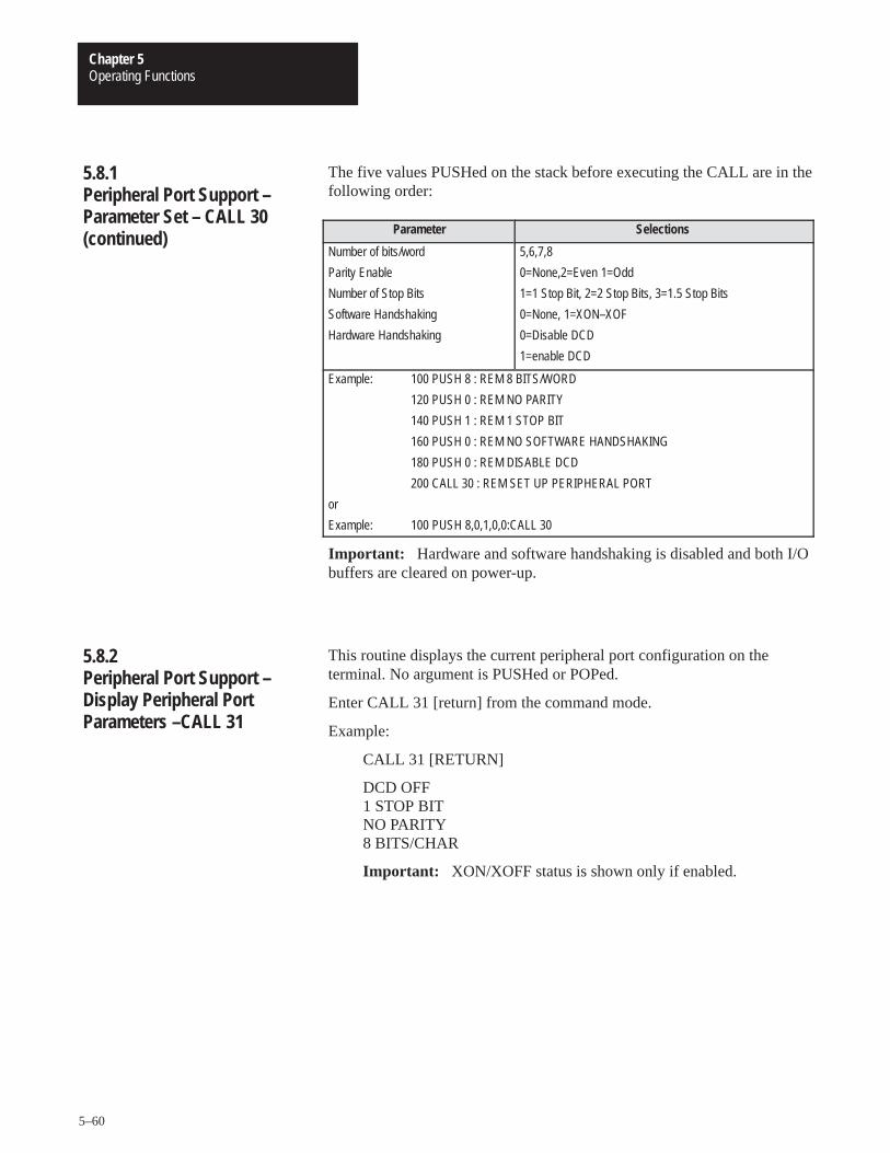
Operating FunctionsChapter 5
5–60
The five values PUSHed on the stack before executing the CALL are in thefollowing order:
Parameter Selections
Number of bits/word
Parity Enable
Number of Stop Bits
Software Handshaking
Hardware Handshaking
5,6,7,8
0=None,2=Even 1=Odd
1=1 Stop Bit, 2=2 Stop Bits, 3=1.5 Stop Bits
0=None, 1=XON–XOF
0=Disable DCD
1=enable DCD
Example: 100 PUSH 8 : REM 8 BITS/WORD
120 PUSH 0 : REM NO PARITY
140 PUSH 1 : REM 1 STOP BIT
160 PUSH 0 : REM NO SOFTWARE HANDSHAKING160 USH 0 EM S FTWA E HA DSHAKI G
180 PUSH 0 : REM DISABLE DCD
200 CALL 30 : REM SET UP PERIPHERAL PORT
or
Example: 100 PUSH 8,0,1,0,0:CALL 30
Important: Hardware and software handshaking is disabled and both I/Obuffers are cleared on power-up.
This routine displays the current peripheral port configuration on theterminal. No argument is PUSHed or POPed.
Enter CALL 31 [return] from the command mode.
Example:
CALL 31 [RETURN]
DCD OFF 1 STOP BIT NO PARITY 8 BITS/CHAR
Important: XON/XOFF status is shown only if enabled.
5.8.1Peripheral Port Support –Parameter Set – CALL 30(continued)
5.8.2Peripheral Port Support –Display Peripheral PortParameters –CALL 31
Operating FunctionsChapter 5
5–61
Important: Maximum baud rate is 2400 bps for all data recorder CALLroutines. The Peripheral Port is set up in these routines and does not needsetting in BASIC.
This routine saves the current RAM program on a 1770–SA/SB recorder.The program in RAM is not modified. The message ERROR—IN ROMdisplays if ROM is selected instead of RAM.
To use this routine:
insert the cassette/cartridge into the recorder and rewind.
enter CALL 32. The terminal responds with “POSITION TAPE ANDPRESS WRITE/RECORD ON TAPE”.
Press RECORD. The module begins sending data to the recorder. Anasterisk is displayed on the terminal as each program line is sent to therecorder.
During this time the “DATA IN” LED on the data recorder and the XMITLED on the front of the module illuminate. When the last line of programis sent to the recorder, a final asterisk is displayed on the terminalindicating that the save operation is complete. Finally, tape motion ceasesand the BASIC prompt (�) is displayed.
Press STOP if you are using a 1770–SA Recorder.
Important: If there is no program in RAM, the module displays themessage ERROR–NO BASIC PROGRAM EXISTS.
Important: Maximum baud rate is 2400 bps for all data recorder CALLroutines. The Peripheral Port is set up in these routines and does not needsetting in BASIC. See section 4.2.2.2 for required cable connections.
This routine is used to verify the current RAM program with a previouslystored program on the data recorder. To use this routine:
insert the cassette cartridge into the recorder and rewind.
enter CALL 33. The terminal responds with “POSITION TAPE ANDPRESS READ FROM TAPE”.
5.8.3Save Program to DataRecorder – CALL 32
5.8.4Verify Program with DataRecorder – CALL 33
Operating FunctionsChapter 5
5–62
Press PLAY. Tape movement begins and the recorder searches for thebeginning of the next program. As each line of the program verifies, anasterisk displays.
During this time the “DATA OUT” LED on the recorder and the“RECV” LED on the module illuminate. When the last line of programis verified a final asterisk is displayed on the terminal followed by the“VERIFICATION COMPLETE” message and the BASIC (�) prompt.If any differences between programs are encountered, the routinedisplays an “ERROR–VERIFICATION FAILURE” message and theBASIC (�) prompt is immediately displayed.
Important: Maximum baud rate is 2400 bps for all data recorder CALLroutines. The UART is set up in these routines and does not need setting inBASIC. See section 4.2.2.2 for required cable connections.
This routine loads a program stored on a 1770–SA/SB recorder into userRAM, destroying the previous contents of RAM. To use this routine:
enter CALL 34. The terminal responds with “POSITION TAPE ANDPRESS READ FROM TAPE”.
Press PLAY. Tape movement begins and the routine searches for thebeginning of the next program. When the program is found an asterisk isprinted for each line read from the recorder.
During this time the “DATA OUT” LED of the recorder and the “RECV”LED on the front of the module illuminate. When the recorder sends thelast line of program, a final asterisk appears on the terminal indicating thatthe load operation is complete. Tape motion ceases and the BASIC prompt(�) appears.
If you are using a 1770–SA Recorder, press STOP.
Important: This routine loads the first program encountered and does notdistinguish between labelled programs. See section 5.8.10 below titled,“Load Labeled Program from Data Recorder (1770–SB only) CALL 39″for an explanation of labelled programs.
5.8.4Verify Program with DataRecorder – CALL 33(continued)
5.8.5Load Program from DataRecorder – CALL 34
Operating FunctionsChapter 5
5–63
This routine gets the current character in the 255 character, peripheral portinput buffer. It returns the decimal representation of the characters receivedas its output argument. The peripheral port receives data transmitted byyour device and stores it in this buffer. If there is no character, the outputargument is a 0 (null). If there is a character, the output argument is theASCII representation of that character. There is no input argument for thisroutine.
Example:
�10 CALL 35�20 POP X �30 IF X =0 THEN GOTO 10 �40 PRINT CHR(X)
Important: A 0 (null) is a valid character in some communicationsprotocols. You should use CALL 36 to determine the actual number ofcharacters in the buffer.
Important: Purge the buffer before storing data to ensure data validity.
5.8.6Get Numeric InputCharacter from PeripheralPort – CALL 35
Operating FunctionsChapter 5
5–64
Example:
�10 REM PERIPHERAL PORT INPUT USING CALL 35 �20 STRING 200,20 �30 DIM D(254) �40 CALL 35: POP X �50 IF X ��2 GOTO 40 �55 REM WAIT FOR DEVICE TO SEND START OF TEXT �60 REM �70 DO �80 I=I+1 �90 CALL 35: POP D(I) : REM STORE DATA IN ARRAY �100 UNTIL D(I)=3 : REM WAIT FOR DEVICE TO SEND END OF TEXT �120 REM �130 REM FORMAT AND PRINT DATA TYPES �140 PRINT “RAW DATA=” �150 FOR J=1 TO I : PRINT D(J), : NEXT J �155 REM PRINT RAW DECIMAL DATA �160 PRINT: PRINT: PRINT �170 PRINT “ASCII DATA=” �180 FOR J=1 TO I : PRINT CHR(D(J)), : NEXT J �185 REM PRINT ASCII DATA �190 PRINT: PRINT: PRINT �200 PRINT “$(1)=” �210 FOR J=1 TO I : ASC($(1),J)=D(J) : NEXT J �215 REM STORE DATA IN STRING �220 PRINT $(1) �230 PRINT: PRINT: PRINT �240 I=0 �250 REM �260 GOTO 40
READY �RUN
RAW DATA=65 66 67 68 69 70 71 49 50 51 52 53 54 55 56 57 3
ASCII DATA= ABCDEFG123456789
$(1)= ABCDEFG123456789
READY �
5.8.6Get Numeric InputCharacter from PeripheralPort – CALL 35 (continued)
Operating FunctionsChapter 5
5–65
Use this routine to retrieve the number of characters in the chosen buffer asits output argument. You must PUSH which buffer is to be examined.
PUSH 1 for the input buffer.
PUSH 0 for the output buffer.
One POP is required to get the number of characters.
Example:
�10 PUSH 0: REM examines the output buffer�20 CALL 36�30 POP X: REM get the number of characters�40 PRINT “Number of characters in the Output Buffer is”,X�50 END
This routine clears either the peripheral ports input or output buffer.
PUSH 0 to clear the output buffer.
PUSH 1 to clear the input buffer.
PUSH 2 to clear both buffers.
Example:
�10 PUSH 0: REM clears the output buffer �20 CALL 37 �30 END
Important: Maximum baud rate is 2400 bps for all data recorder CALLroutines. The Peripheral Port is set up in these routines and does not needsetting in BASIC. See section 4.4.3 for required cable connections. Tapeverification failures result if you use a cable with different pin connections
This routine is identical to the CALL 32 routine except the program isassigned an ID number (0-255) before storing it on tape. This allows youto search for a specific program on a tape that contains many differentprograms. To do this:
PUSH the ID number.
enter CALL 38. From this point on operation is identical to the CALL32 routine. See section 5.8.3 above titled, “Save Program to DataRecorder – Call 32” for an explanation.
5.8.7Get the Number ofCharacters in the PeripheralPort Buffers – CALL 36
5.8.8Clear the Peripheral PortsInput or Output Buffer –CALL 37
5.8.9Save Labeled Program toData Recorder (1770-SB only)– CALL 38
Operating FunctionsChapter 5
5–66
This routine has one input argument and no output arguments. If no IDnumber is pushed prior to CALL 38, an error occurs and the routine abortswithout saving.
An unlabeled save (CALL 32) has an ID of 0.
Important: Do not press rewind between programs saved. If you pressrewind only the last program is saved.
Important: Maximum baud rate is 2400 bps for all data recorder CALLroutines. The Peripheral Port is set up in these routines and does not needsetting in BASIC. The Peripheral Port parameters restore when the call iscomplete. See section 4.4.3 for required cable connections. Tapeverification failures result if you use a cable with different pin connections.
This routine is identical to the CALL 34 routine except that labeledprograms are organized according to an ID number (0-255) assigned to thestored program using a CALL 38. To use this routine:
PUSH the ID number.
Enter CALL 39. From this point on, operation is identical to the CALL34 routine. See Section 5.8.4 above titled, “Verify Program with DataRecorder – CALL 33” for explanation.
This routine has one input argument and no output arguments. If no IDnumber is pushed prior to CALL 38, an error occurs and the routine abortswithout saving.
While searching for the correct program, one asterisk prints for eachprogram encountered. When the correct program is found one asterisk perline prints. You must press the READ FROM TAPE button twice on theSB Recorder at the end of each program encountered to continue thesearch. Press the READ FROM TAPE button when the DATA OUT lighton the SB Recorder goes out. This indicates the end of file. If the BASICModule starts loading from the middle of a file, the DATA OUT light is onbut no asterisk is printed on the console. Follow the above procedure tocontinue the search.
An unlabeled save (CALL 32) has an ID of 0.
CALL 110 prints the complete buffer with addresses, front pointer and thenumber of characters in the buffer to the console. No PUSHes or POPs areneeded. Use this information as a troubleshooting aid. It does not affect thecontents of the buffer.
5.8.9Save Labeled Program toData Recorder (1770-SB only)– CALL 38 (continued)
5.8.10Load Labeled Program fromData Recorder (1770-SB only)– CALL 39
5.8.11Print the Peripheral PortOutput Buffer and Pointer –CALL 110
Operating FunctionsChapter 5
5–67
CALL 111 prints the complete buffer with addresses, front pointer and thenumber of characters in the buffer to the console. No PUSHes or POPs areneeded.
Use this information as a troubleshooting aid. It does not affect thecontents of the buffer.
CALL 119 resets the peripheral port to the following default settings:
8 bits/character
1 stop bit
No parity
DCD off
XON-XOFF off
No PUSHes or POPs are needed.
The battery backed wall time clock provides year, month, day of month,day of week, hours, minutes and seconds. The clock operates in 24 hourmilitary time format. The support routines allow the setting of the clockand retrieval of clock values in numeric form.
The wall clock support routines use the argument stack to pass databetween the BASIC program and the routines. Data is passed in bothdirections and consists of the actual clock data.
The wall clock or time of day clock is separate from the real time clockalso provided on the module. The real time clock is accessed by CLOCK 1,CLOCK0, ONTIME and other statements, and has a resolution of 5milliseconds. It should be used for all short time interval measurementsbecause the greater resolution results in more accurate timing. The twoclocks are not synchronized and comparison of times is not recommended.Also, the real time clock is not battery backed.
5.8.12Print the Peripheral PortInput Buffer and Pointer –CALL 111
5.8.13Reset the Peripheral Portto Default Settings – CALL 119
5.9Wall Clock Support Calls
Operating FunctionsChapter 5
5–68
Use this routine to set the following wall clock time functions:
H = hours (0 to 23)
M = minutes (0 to 59)
S = seconds(0-59)
Example:
Program the wall clock for 1:35 pm (13:35 on a 24 hour clock).
�10 H=13: M=35: S=00 :REM HOURS=13; MINUTES=35; SECONDS=00�20 PUSH H,M,S :REM PUSH HOURS, MINUTES, SECONDS�30 CALL 40 :REM CALL THE ROUTINE TO SET THE WALL CLOCK TIME
Use this routine to set the following wall clock functions:
D = day
M = month
Y = year
Three values are PUSHed and none POPed.
Example:
Program the wall clock for the 16th day of June, 1985
�10 D=16: M=06: Y=85 :REM DAY OF MONTH = 16, MONTH = 6, YEAR = 85�20 PUSH D,M,Y :REM PUSH DAY OF MONTH, MONTH, YEAR�30 CALL 41 :REM CALL THE ROUTINE TO SET THE WALL CLOCK DATE
CALL 42 sets the day of the week. Sunday is day 1. Saturday is day 7.
Example:
�PUSH 3 : CALL 42 REM DAY IS TUESDAY.
5.9.1Setting the Wall Clock Time(Hour, Minute, Second) –CALL 40
5.9.2Setting the Wall Clock Date(Day, Month, Year) – CALL 41
5.9.3Set Wall Clock – Day of Week– CALL 42
Operating FunctionsChapter 5
5–69
CALL 43 returns the current date and time as a string. PUSH the numberof the string to receive the date/time (dd/mmm/yy HH:MM:SS). You mustallocate a minimum of 18 characters for the string. This requires you to setthe maximum length for all strings to at least 18 characters.
Example:
�10 STRING 100,20 �20 PUSH 1: CALL 43: REM put date/time in string 1 �30 PRINT $(1) �40 END
CALL 44 returns the current date on the argument stack as three numbers.There is no input argument to this routine and three variables are returned.The date is POPed in day, month and year order.
Example:
�10 REM DATE RETRIEVE – NUMERIC EXAMPLE �20 CALL 44: REM INVOKE THE UTILITY ROUTINE �30 POP D,M1,Y : REM GET THE DATA FROM THE 30 STACK �40 PRINT “CURRENT DATE IS”, Y,M1,D �50 END�RUN
CURRENT DATE IS 84 12 25
READY
CALL 45 returns the current time in a string (HH:MM:SS). PUSH thenumber of the string to receive the time. You must allocate a minimum of 8characters for the string.
Example:
�10 STRING 100,20 �20 PUSH 1, CALL 45: REM put time in string 1 �30 PRINT $(1) �40 END
5.9.4Date/Time Retrieve String –CALL 43
5.9.5Date Retrieve Numeric (Day,Month, Year) – CALL 44 (2)
5.9.6Time Retrieve String –CALL 45
Operating FunctionsChapter 5
5–70
The time of day is available in numeric form by executing a CALL 46 andPOPing the three variables off of the argument stack on return. There areno input arguments. The time is POPed in hour, minute and second order.
Example:
�10 REM TIME IN VARIABLES EXAMPLE : REM GET THE WALL CLOCK TIME �20 CALL 46 �30 POP H,M,S �40 PRINT “CURRENT TIME IS”, H,M,S 50 END
�RUN
CURRENT TIME IS 13 44 54
READY
CALL 47 returns the current day of week as a three character string. PUSHthe number of the string to receive the day of week. You must allocate aminimum of 3 characters/string. Strings returned are SUN, MON, TUE,WED, THUR, FRI, SAT.
Example:
�10 PUSH 0: CALL 47 �20 PRINT “TODAY IS”,$(0)
CALL 48 returns the current day of week on the argument stack as anumber (i.e. Sunday = 1, Saturday = 7). This can be POPed into a variable.
Example:
�10 REM DAY OF WEEK RETRIEVE – NUMERIC EX �20 CALL 44: REM INVOKE UTILITY TO GET D.O.W. �30 POP D
5.9.7Time Retrieve Number – Call46
5.9.8Retrieve Day of WeekString – CALL 47
5.9.9Retrieve Day of WeekNumeric – CALL 48
Operating FunctionsChapter 5
5–71
CALL 52 returns the current date in a string (dd/mmm/yy). PUSH thenumber of the string to receive the date. You must allocate a minimum of 9characters for the string.
Example:
�10 STRING 100,20 �20 PUSH 1: CALL 52: REM put date in string 1 �30 PRINT $(1) �40 END �RUN
30/JAN/87
A string is a character or group of characters stored in memory. Usually,the characters stored in a string make up a word or a sentence. Stringsallow you to deal with words instead of numbers. This allows you to referto individuals by name instead of by number.
The BASIC Module contains one dimensioned string variable, $([expr]).The dimension of the string variable (the [expr] value) ranges from 0 to254. This means that you can define and manipulate 255 different stringsin the BASIC Module. Initially, no memory is allocated for strings.Memory is allocated by the STRING [expr], [expr] STATEMENT. SeeSection 5.4.31 for more information on this statement.
In the BASIC Module you can define strings with the LET statement, theINPUT statement and with the ASC () operator.
Example:
�10 STRING 100,20 �20 $(1)=“THIS IS A STRING,” �30 INPUT “WHAT’S YOUR NAME? – ”,$(2) �40 PRINT $(1),$(2) �50 END �RUN
WHAT’S YOUR NAME? – FRED
THIS IS A STRING, FRED
You can also assign strings to each other with a LET statement.
Example:
LET $(2)=$(1)
Assigns the string value in $(1) to the STRING $(2).
5.9.10Date Retrieve String – CALL 52
5.10Description of StringOperators
Operating FunctionsChapter 5
5–72
Two operators in the BASIC Module can manipulate STRINGS. Theseoperators are ASC() and CHR(). The ASC() operator returns the integervalue of the ASCII character placed in the parentheses.
Example:
�PRINT ASC(A) 65
The decimal representation for the ASCII character “A” is 65. In addition,you can evaluate individual characters in a pre-defined ASCII string withthe ASC() operator.
Example:
�5 STRING 1000,40 �10 $(1)=“THIS IS A STRING” �20 PRINT $(1) �30 PRINT ASC($(1),1) �40 END �RUN
THIS IS A STRING84
When you use the ASC() operator as shown above, the $([expr]) denoteswhat string is accessed. The expression after the comma selects anindividual character in the string. In the above example, the first characterin the string is selected. The decimal representation for the ASCIIcharacter “T” is 84. String character position 0 is invalid.
Example:
�5 STRING 1000,40 �10 $(1)=“ABCDEFGHIJKL” �20 FOR X=1 TO 12 �30 PRINT ASC($(1),X), �40 NEXT X �50 END �RUN
65 66 67 68 69 70 71 72 73 74 75 76
The numbers printed in the previous example represent the ASCIIcharacters A through L.
5.10.1The ASC Operator
Operating FunctionsChapter 5
5–73
You can also use the ASC() operator to change individual characters in adefined string.
Example:
�5 STRING 1000,40 �10 $(1)=“ABCDEFGHIJKL” �20 PRINT $(1) �30 ASC($(1),1)=75 REM: DECIMAL EQUIVALENT OF K �40 PRINT $(1) �50 ASC($(1),2)=ASC($(1),3) �60 PRINT $(1) �RUN
ABCDEFGHIJKL KBCDEFGHIJKL KCCDEFGHIJKL
In general, the ASC() operator lets you manipulate individual characters ina string. A simple program can determine if two strings are identical.
Example:
�5 STRING 1000,40 �10 $(1)=“SECRET” : REM SECRET IS THE PASSWORD �20 INPUT “WHAT’S THE PASSWORD – ”,$(2) �30 FOR I=1 TO 6 �40 IF ASC($(1),I)=ASC($(2),I) THEN NEXT I ELSE 70 �50 PRINT “YOU GUESSED IT!” �60 END �70 PRINT “WRONG, TRY AGAIN” : GOTO 20 �RUN
WHAT’S THE PASSWORD – SECURE WRONG, TRY AGAIN WHAT’S THE PASSWORD – SECRET YOU GUESSED IT
5.10.1The ASC Operator(continued)
Operating FunctionsChapter 5
5–74
The CHR() operator converts a numeric expression to an ASCII character.
Example:
�PRINT CHR(65) A
Like the ASC() operator, the CHR() operator also selects individualcharacters in a defined ASCII string.
Example:
�5 STRING 1000,40 �10 $(1)=“The BASIC Module” �20 FOR I=1 TO 16 : PRINT CHR($(1),I), : NEXT I �30 PRINT: FOR I=16 TO 1 STEP -1 �40 PRINT CHR($(1),I), : NEXT I �RUN
The BASIC Module
eludoM CISAB ehT
In the above example, the expressions contained within the parenthesis,following the CHR operator have the same meaning as the expressions inthe ASC() operator.
Unlike the ASC() operator, you CANNOT assign the CHR() operator avalue. A statement such as CHR($(1),1) = H, is INVALID and generates aBAD SYNTAX ERROR. Use the ASC() operator to change a value in astring, or use the string support call routine – replace string in a string. SeeSection 5.10.3 below titled, “String Support Calls” for more information.
Important: Use the CHR() function only in a print statement.
5.10.2.1 Clearing the Screen on an Allen-Bradley Industrial Terminal
Refer to Appendix B at the rear of this manual. In “Column 1” under”DEC”, you find that 12 equals ASCII FF (form feed). Type PRINTCHR(12) to clear the industrial terminal screen with a form feed.
5.10.2The CHR Operator
Operating FunctionsChapter 5
5–75
5.10.2.2 Cursor Positioning on an Industrial Terminal
Allen-Bradley Industrial Terminal – Refer to the Industrial Terminal User’sManual (publication number 1770-6.5.3), Table 6-3. You can controlcursor positioning by typing:
(CTRL)(P)(COLUMN#)(;)(ROW#)(A).
The ASCII equivalent of (CTRL)(P) is DLE. Using Appendix B, the DECequivalent of ASCII DLE is 16.
PRINT CHR(16), “40;10ATEST”
This prints “TEST” at column 40 row 10 on your Allen-Bradley IndustrialTerminal.
To enhance the BASIC Module we have added several string manipulationroutines that make programming easier. Strings in the BASIC Module aredeclared by the STRING statement. You must execute the STRINGstatement before you can access or call any strings or string routines. TheSTRING statement has two arguments or numbers that follow it. They are:
the total amount of space to allocate to string storage and,
the maximum size in characters of each string.
Since you terminate strings using a carriage return character, each string isgiven an extra byte of storage for its carriage return if it is the maximumlength. You can determine the number of strings allowed by taking the firstnumber and dividing it by one plus the second number. Note that you mustuse the strings consecutively starting with string 0 through the allowednumber of strings. All strings are allocated the maximum number ofcharacters regardless of the actual number used.
All of these routines use or modify strings as part of their operation. Themechanism for passing a string to the support routine is to PUSH itsnumber or subscript onto the stack. The support routine can then get thestring number from the module’s argument stack, and locate it in stringmemory.
Many of these routines also require the length of a string as an input. Thisnumber must normally be inclusively between zero and the second numberused in the last STRING statement which specifies the maximum size of astring. However, in all cases, if a string length argument of minus one ( -1)is given, it is interpreted as the maximum allowable string length.
5.10.2The CHR Operator (continued)
5.10.3String Support Calls

Operating FunctionsChapter 5
5–76
It is important to note that since the carriage return character is the stringterminator, you cannot use it within a string as one of its characters. If thehigh bit is set in a carriage return character (use 141 instead of 13 as thedecimal value of the carriage return character) the BASIC Module does notrecognize it as the end of string character and passes it to the output device.Most devices use a seven bit ASCII code, ignore the top bit and treat the141 as a normal carriage return.
Important: All undefined characters of a string (i.e. characters followingCR) are nulls. If data is input to a string using the ASC($(X),I) command,you must be sure the string is (CR) terminated properly. You can initializethe string or add a (CR) to terminate the string.
Example:
�10 STRING 100,10�20 FOR I=1 TO 5�30 ASC($(0),I)=65�40 NEXT I�50 PRINT $(0)�RUNAAAAA
The string is stored in memory without a (CR) terminator. Be sure to inserta (CR) (0DH) into the last position of the string if using the above method.
Example:
�10 STRING 100,10�20 FOR I=1 TO 5�30 ASC ($(0),I) = 65�40 NEXT I�45 ASC($(0),6)=0DH�50 PRINT $(0)or
�10 STRING 100,10�15 $(0))=“ ”�20 FOR 1 TO 5�30 ASC ($(0),I) = 65�40 NEXT I�50 PRINT $(0)
The following three programs allow you to determine how much stringspace to allocate when you know two of three variables associated with thestrings:
number of characters in the longest string.
number of string variables.
amount of memory to allocate for strings.
5.10.3String Support Calls(continued)
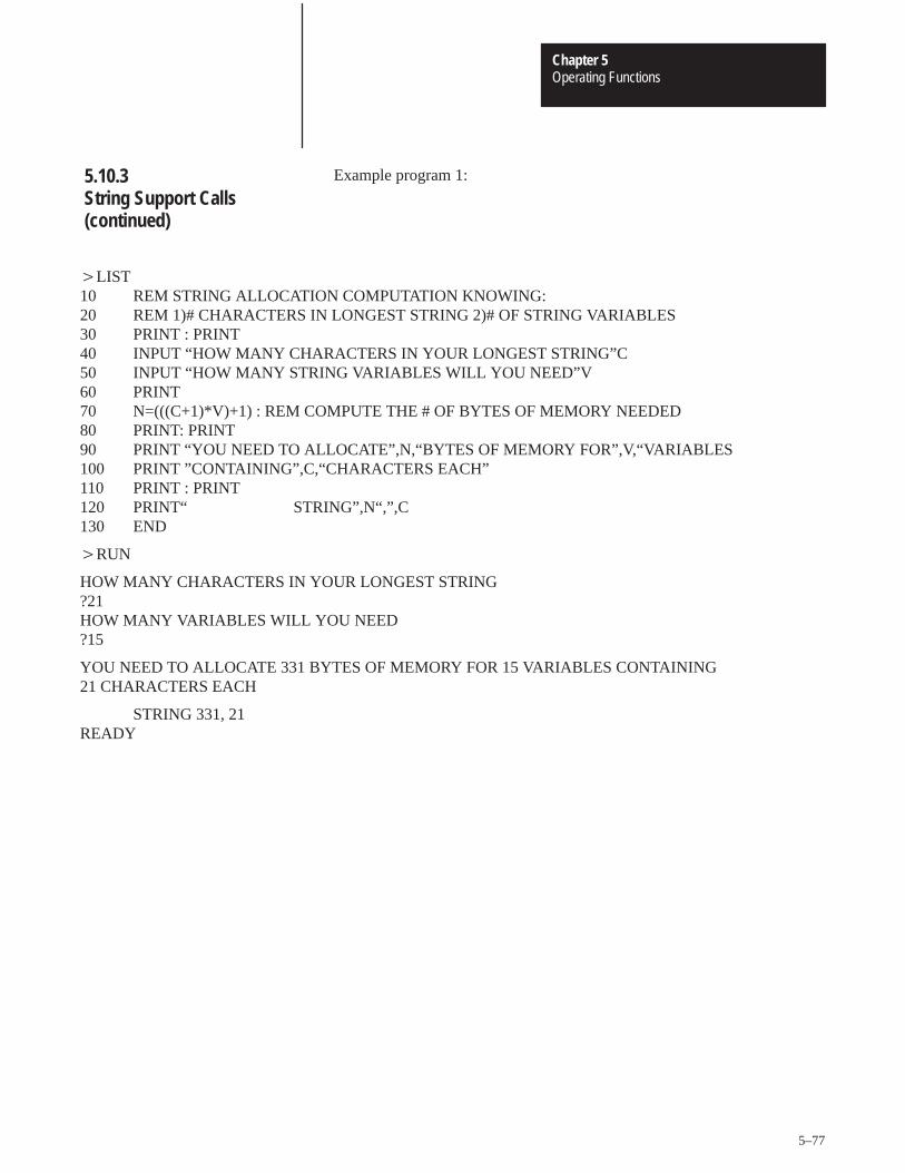
Operating FunctionsChapter 5
5–77
Example program 1:
�LIST 10 REM STRING ALLOCATION COMPUTATION KNOWING: 20 REM 1)# CHARACTERS IN LONGEST STRING 2)# OF STRING VARIABLES30 PRINT : PRINT 40 INPUT “HOW MANY CHARACTERS IN YOUR LONGEST STRING”C 50 INPUT “HOW MANY STRING VARIABLES WILL YOU NEED”V 60 PRINT 70 N=(((C+1)*V)+1) : REM COMPUTE THE # OF BYTES OF MEMORY NEEDED 80 PRINT: PRINT 90 PRINT “YOU NEED TO ALLOCATE”,N,“BYTES OF MEMORY FOR”,V,“VARIABLES 100 PRINT ”CONTAINING”,C,“CHARACTERS EACH” 110 PRINT : PRINT 120 PRINT“ STRING”,N“,”,C 130 END
�RUN
HOW MANY CHARACTERS IN YOUR LONGEST STRING?21HOW MANY VARIABLES WILL YOU NEED?15
YOU NEED TO ALLOCATE 331 BYTES OF MEMORY FOR 15 VARIABLES CONTAINING 21 CHARACTERS EACH
STRING 331, 21 READY
5.10.3String Support Calls(continued)
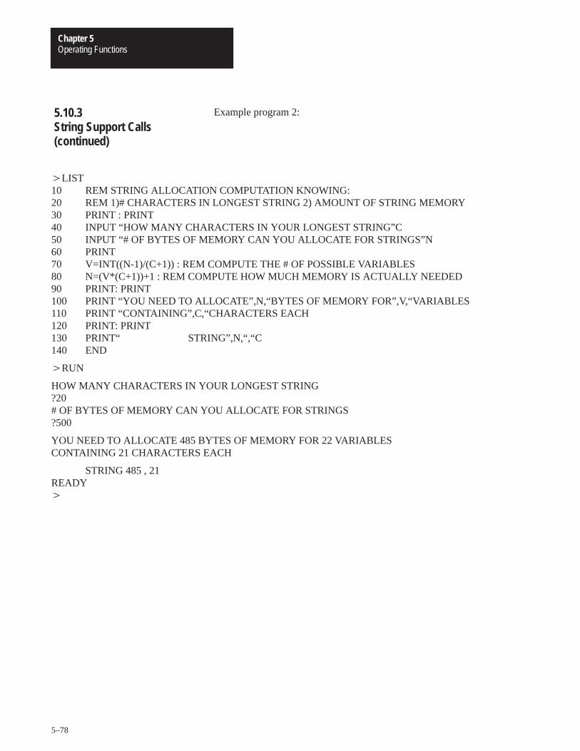
Operating FunctionsChapter 5
5–78
Example program 2:
�LIST 10 REM STRING ALLOCATION COMPUTATION KNOWING: 20 REM 1)# CHARACTERS IN LONGEST STRING 2) AMOUNT OF STRING MEMORY 30 PRINT : PRINT 40 INPUT “HOW MANY CHARACTERS IN YOUR LONGEST STRING”C 50 INPUT “# OF BYTES OF MEMORY CAN YOU ALLOCATE FOR STRINGS”N 60 PRINT 70 V=INT((N-1)/(C+1)) : REM COMPUTE THE # OF POSSIBLE VARIABLES 80 N=(V*(C+1))+1 : REM COMPUTE HOW MUCH MEMORY IS ACTUALLY NEEDED 90 PRINT: PRINT 100 PRINT “YOU NEED TO ALLOCATE”,N,“BYTES OF MEMORY FOR”,V,“VARIABLES 110 PRINT “CONTAINING”,C,“CHARACTERS EACH 120 PRINT: PRINT 130 PRINT“ STRING”,N,“,“C 140 END
�RUN
HOW MANY CHARACTERS IN YOUR LONGEST STRING?20# OF BYTES OF MEMORY CAN YOU ALLOCATE FOR STRINGS?500
YOU NEED TO ALLOCATE 485 BYTES OF MEMORY FOR 22 VARIABLESCONTAINING 21 CHARACTERS EACH
STRING 485 , 21READY �
5.10.3String Support Calls(continued)
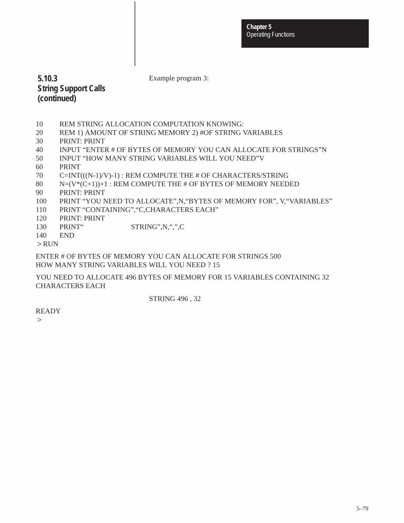
Operating FunctionsChapter 5
5–79
Example program 3:
10 REM STRING ALLOCATION COMPUTATION KNOWING: 20 REM 1) AMOUNT OF STRING MEMORY 2) #OF STRING VARIABLES 30 PRINT: PRINT 40 INPUT “ENTER # OF BYTES OF MEMORY YOU CAN ALLOCATE FOR STRINGS”N 50 INPUT “HOW MANY STRING VARIABLES WILL YOU NEED”V 60 PRINT 70 C=INT(((N-1)/V)-1) : REM COMPUTE THE # OF CHARACTERS/STRING 80 N=(V*(C+1))+1 : REM COMPUTE THE # OF BYTES OF MEMORY NEEDED90 PRINT: PRINT 100 PRINT “YOU NEED TO ALLOCATE”,N,“BYTES OF MEMORY FOR”, V,“VARIABLES” 110 PRINT “CONTAINING”,“C,CHARACTERS EACH” 120 PRINT: PRINT 130 PRINT“ STRING”,N,“,”,C 140 END �RUN
ENTER # OF BYTES OF MEMORY YOU CAN ALLOCATE FOR STRINGS 500 HOW MANY STRING VARIABLES WILL YOU NEED ? 15
YOU NEED TO ALLOCATE 496 BYTES OF MEMORY FOR 15 VARIABLES CONTAINING 32CHARACTERS EACH
STRING 496 , 32
READY�
5.10.3String Support Calls(continued)
Operating FunctionsChapter 5
5–80
5.10.3.1 String Repeat – CALL 60
This routine allows you to repeat a character and place it in a string. Youcan use the String Repeat when designing output formats. First PUSH thenumber of times to repeat the character, then PUSH the number of thestring containing the character to be repeated. No arguments are POPed.You cannot repeat more characters than the string’s maximum length.
�10 REM STRING REPEAT EXAMPLE PROGRAM �20 STRING 1000,50 �30 $(1)=“*” �40 PUSH 40 :REM THE NUMBER OF TIMES TO REPEAT CHARACTER �50 PUSH 1 :REM WHICH STRING CONTAINS CHARACTER �60 CALL 60 �70 PRINT $(1) �80 END �RUN***************************************** READY
5.10.3String Support Calls(continued)

Operating FunctionsChapter 5
5–81
5.10.3.2 String Append (Concatenation) – CALL 61
This routine allows you to append one string to the end of another string.The CALL expects two string arguments. The first is the string number ofthe string to be appended and the second is the string number of the basestring. If the resulting string is longer than the maximum string length, theappend characters are lost. There are no output arguments. This is a stringconcatenation assignment. (Example: $(1)=$(1)+$(2)).
�10 STRING 200,20 �20 $(1)=“How are” �30 $(2)=“you?” �40 PRINT “BEFORE:”, �50 PRINT “$1=”,$(1),“ $2=”,$(2) �60 PUSH 2 :REM STRING NUMBER OF STRING TO BE APPENDED �70 PUSH 1 :REM BASE STRING NUMBER �80 CALL 61 :REM INVOKE STRING CONCATENATION ROUTINE �90 PRINT “AFTER:”, �100 PRINT “$1=”,$(1),“ $2=”,$(2) �110 END
�RUN
BEFORE: $1=How are $2=you? AFTER: $1=How are you? $2=you?
READY
5.10.3.3 Number to String Conversion – CALL 62
This routine converts a number or numeric variable into a string. You mustallocate a minimum of 14 characters for the string. If the exponent of thevalue to be converted is anticipated to be 100 or greater, you must allocate15 characters. Error checking traps string allocation of less than 14characters only.
PUSH the value to be converted
PUSH the number of the string to receive the value.
Example:
�10 STRING 100,14�20 INPUT “ENTER A NUMBER TO CONVERT TO A STRING ”,N �30 PUSH N�40 PUSH 1: REM CONVERT NUMBER TO STRING 1�50 CALL 62: REM DO THE CONVERSION�60 PRINT $(1)�70 END
5.10.3String Support Calls(continued)
Operating FunctionsChapter 5
5–82
5.10.3.4 String to Number Conversion – CALL 63
This routine converts the first decimal number found in the specified stringto a number on the argument stack. Valid numbers and associatedcharacters are: 0, 1, 2, 3, 4, 5, 6, 7, 8, 9, ., E, +, -. The comma (,) is not avalid number character and terminates the conversion. Two bytes arePOPed after the CALL:
validity of the value
actual value
If the string does not contain a legal value a 0 (zero) is returned. A validvalue is between 1 and 255. PUSH the number of the string to convert.Two POPs are required. First POP the validity value, then POP the value.If a string contains a number followed by an E followed by a letter ornon-numeric character, it is assumed that no number was found since theletter is not a valid exponent (UAB701EA returns a zero in the firstargument popped indicating that no valid number was in the string).
Example:
�10 STRING 100,14 �20 INPUT “ENTER A STRING TO CONVERT”,$(1) �30 PUSH 1: REM CONVERT STRING 1 �40 CALL 63: REM DO THE CONVERSION �50 POP V,N �60 IF V �� 0 THEN PRINT $(1),“ ”,N: GO TO 80 �70 PRINT “INVALID OR NO VALUE FOUND” 80 END
5.10.3String Support Calls(continued)
Operating FunctionsChapter 5
5–83
5.10.3.5 Find a String in a String – CALL 64
This routine finds a string within a string. It locates the first occurrence(position) of this string. This call expects two input arguments . The first isthe string to be found, the second is the string to be searched for a match.One return argument is required. If the number is not zero then a matchwas located at the position indicated by the value of the return argument.This routine is similar to the BASIC INSTR$(findstr$,str$). (Example:L=INSTR$($(1),$(2))
�10 REM SAMPLE FIND STRING IN STRING ROUTINE�20 STRING 1000,20�30 $(1)=“456” �40 $(2)=“12345678” �50 PUSH 1 :REM STRING NUMBER OF STRING TO BE FOUND�60 PUSH 2 :REM BASE STRING NUMBER �70 CALL 64 :REM GET LOCATION OF FIRST CHARACTER�80 POP L �90 IF L=0 THEN PRINT “NOT FOUND”�100 IF L�0 THEN PRINT “FOUND AT LOCATION ”,L�110 END
�RUN
FOUND AT LOCATION 4
READY
5.10.3String Support Calls(continued)
Operating FunctionsChapter 5
5–84
5.10.3.6 Replace a String in a String – CALL 65
This routine replaces a string within a string. Three arguments areexpected. The first argument is the string number of the string whichreplaces the string identified by the second argument string number. Thethird argument is the base string’s string number. There are no returnarguments.
�10 REM SAMPLE OF REPLACE STRING IN STRING �20 STRING 1000,20 �30 $(0)=“RED-LINES” �40 $(1)=“RED” �50 $(2)=“BLUE” �60 PRINT “BEFORE: $0=”,$(0) �70 PUSH 2 :REM STRING NUMBER OF THE STRING TO REPLACE WITH �80 PUSH 1 :REM STRING NUMBER OF THE STRING TO BE REPLACED �90 PUSH 0 :REM BASE STRING NUMBER �100 CALL 65 :REM INVOKE REPLACE STRING IN STRING ROUTINE �110 PRINT “AFTER: $0=”,$(0) �120 END RUN BEFORE: $=RED-LINES AFTER: $0=BLUE-LINES READY
5.10.3String Support Calls(continued)

Operating FunctionsChapter 5
5–85
5.10.3.7 Insert String in a String – CALL 66
This routine inserts a string within another string. The call expects threearguments. The first argument is the position at which to begin the insert.The second argument is the string number of the characters inserted intothe base string. The third argument is the string number of the base string.This routine has no return arguments.
�10 REM SAMPLE ROUTINE TO INSERT A STRING IN A STRING �20 STRING 500,15 �30 $(0)=“1234590” �40 $(1)=“67890” �50 PRINT “BEFORE: 0$=”,$(0) �60 PUSH 6 :REM POSITION TO START THE INSERT �70 PUSH 1 :REM STRING NUMBER OF THE STRING TO BE INSERTED�80 PUSH 0 :REM BASE STRING NUMBER �90 CALL 66 :REM INVOKE INSERT A STRING IN A STRING �91 REM :REM ROUTINE �100 PRINT “AFTER: 0$=”,$(0) �110 END
�RUN
BEFORE: 0$=1234590 AFTER: 0$=1234567890 READY
5.10.3String Support Calls(continued)

Operating FunctionsChapter 5
5–86
5.10.3.8 Delete String from a String – CALL 67
This routine deletes a string from within another string. The call expectstwo arguments. The first argument is the base string number. The second isthe string number of the string to be deleted from the base string. Thisroutine has no return arguments.
Important: This routine deletes only the first occurrence of the string.
�10 REM ROUTINE TO DELETE A STRING IN A STRING�20 STRING 200,14�30 $(1)=“123456789012”�40 $(2)=“12”�50 PRINT “BEFORE: $1=“,$(1)�60 PUSH 1 :REM BASE STRING NUMBER�70 PUSH 2 :REM STRING NUMBER OF THE STRING TO BE DELETED�80 CALL 67 :REM INVOKE STRING DELETE ROUTINE�90 PRINT “AFTER: $1=”,$(1)�100 END
�RUN
BEFORE: $1=123456789012AFTER: $1=3456789012
READY
5.10.3String Support Calls(continued)
Operating FunctionsChapter 5
5–87
5.10.3.9 Determine Length of a String – CALL 68
This routine determines the length of a string. One input argument isexpected. This is the string number on which the routine acts. One outputargument is required. It is the actual number of non-carriage return (CR)characters in this string. This is similar to the BASIC command LEN(str$).(Example: L=LEN($1)).
�10 REM SAMPLE OF STRING LENGTH�20 STRING 100,10�30 $(1)=“1234567”�40 PUSH 1 :REM BASE STRING�50 CALL 68 :REM INVOKE STRING LENGTH ROUTINE�60 POP L :REM GET LENGTH OF BASE STRING�70 PRINT “THE LENGTH OF ”,$(1),“ IS ”,L�80 END
�RUN
THE LENGTH OF 1234567 IS 7
READY
The following sections list and describe the memory support calls you canuse with the BASIC Module. All strings, arrays and variables are shared.
5.10.3String Support Calls(continued)
5.11 Memory Support Calls
Operating FunctionsChapter 5
5–88
This routine shifts program execution from a running ROM program to thebeginning of the RAM program. No arguments are PUSHed or POPed.
Important: The first line of the RAM program is not executed. Werecommend that you make it a remark.
Example:
ROM #5
�10 REM SAMPLE ROM PROG FOR CALL 70 �20 PRINT “NOW EXECUTING ROM #5” �30 CALL 70 :REM GO EXECUTE RAM �40 END
RAM
�10 REM SAMPLE RAM PROGRAM FOR CALL 70 �20 PRINT “NOW EXECUTING RAM” �30 END
�RUN
NOW EXECUTING ROM #5 NOW EXECUTING RAM
This routine transfers from a running ROM or RAM program to thebeginning of any available ROM program. One argument is PUSHed(which ROM program). None are POPed. An invalid program errordisplays and you enter the command mode if the ROM number does notexist.
Important: The first line of the ROM program is not executed. Werecommend that you make it a remark.
Example:
�10 REM THIS ROUTINE WILL CALL AND EXECUTE A ROM ROUTINE �20 INPUT “ENTER ROM ROUTINE TO EXECUTE ”,N �30 PUSH N �40 CALL 71 �50 END
�RUN
ENTER ROM ROUTINE TO EXECUTE 4
5.11.1 ROM to RAM ProgramTransfer – CALL 70
5.11.2 ROM/RAM to ROM ProgramTransfer – CALL 71
Operating FunctionsChapter 5
5–89
The user is now executing ROM 4 if it exists. If the ROM routinerequested does not exist the result is:
PROGRAM NOT FOUND.READY�
This routine allows you to return to the ROM or RAM routine that calledthis ROM or RAM routine. Execution begins on the line following the linethat CALLed the routine. No arguments are PUSHed or POPed. Thisroutine works one layer deep. You may go back to the last CALLingprogram’s next line.
Important: There must be a next line in the ROM or RAM routine,otherwise unpredictable events could occur which may destroy thecontents of RAM. For this reason always be sure that at least one ENDstatement exists following a Call 70 or 71.
Example:
�ROM #1
�10 REM SAMPLE PROG FOR CALL 72 �20 PRINT “NOW EXECUTING ROM #1 �30 PUSH 3 �40 CALL 71 :REM EXECUTE ROM #3 THEN RETURN �50 PRINT “EXECUTING ROM #1 AGAIN” �60 END
ROM #3
�10 REM THIS LINE WONT BE EXECUTED �20 PRINT “NOW EXECUTING ROM #3” �30 CALL 72 �40 END
With ROM #1 selected:
�RUN
NOW EXECUTING ROM #1 NOW EXECUTING ROM #3 EXECUTING ROM #1 AGAIN
READY�
5.11.2 ROM/RAM to ROM ProgramTransfer – CALL 71(continued)
5.11.3 RAM/ROM Return – CALL 72
Operating FunctionsChapter 5
5–90
CALL 73 disables the battery-backed RAM, prints “Battery BackupDisabled” when executed and allows a purging reset. The next power lossdestroys the contents of RAM. When power is reapplied, RAM is clearedand battery back-up is reenabled automatically.
CALL 74 enables the battery-backed RAM and prints “Battery BackupEnabled” when executed. It is enabled on power-up and remains enableduntil you execute a CALL 73 or until the battery fails.
Important: Change MTOP from command mode only to ensure properoperation
CALL 77 reserves the top of RAM memory for protected variable storage.Values are saved if BATTERY-BACKUP is invoked. You store values withthe ST @ command and retrieve them with the LD @ command. Eachvariable stored requires 6 bytes of storage space.
You must subtract 6 times the number of variables to be stored fromMTOP reducing available RAM memory. This value is PUSHed onto thestack as the new MTOP address. All appropriate variable pointers arereconfigured. Do this only in command mode.
Important: Do not let the ST @ address write over the MTOP address.This could alter the value of a variable or string.
Example: For saving 2 variables.
�PRINT MTOP 14335�PRINT MTOP-1214323�PUSH 14323:REM NEW MTOP ADDRESS �CALL 77
�10 K = 678 * PI �15 L =520 PUSH K �30 ST @ 14335:REM STORE K IN PROTECTED AREA �40 PUSH L �50 ST @ 14329 �55 REM TO RETRIEVE PROTECTED VARIABLES �60 LD@ 14335:REM REMOVE K FROM PROTECTED AREA �70 POP K �80 LD@ 14329 �90 POP L �100 REM USE LD@ AFTER POWER LOSS AND BATTERY BACK-UP IS USED
5.11.4 Battery-backed RAM Disable – CALL 73
5.11.5 Battery-backed RAM Enable – CALL 74
5.11.6 Protected Variable Storage – CALL 77
Operating FunctionsChapter 5
5–91
Example:
For using protected variable storage area.
A. Scalar Variables
Push all variables in one line:
�PRINT MTOP 14335 �PRINT MTOP-24 14311 �PUSH 14311:REM NEW MTOP ADDRESS CALL 77
90 M1=14335 : REM BEGIN STORING HERE 100 PUSH A, B, C, D
Use the ST @ and LD @ commands in a DO loop:
�200 DO �210 ST @ M1 �220 M1=M1-6 : REM EACH VARIABLE =6 BYTES �230 UNTIL M1=MTOP: REM YOU DEFINED THE NEW MTOP W/CALL 77 �290 M1=14335 �300 DO �310 LD @ M1 �320 M1 = M1-6 �330 UNTIL M1 = MTOP �360 POP A, B, C, D �370 PRINT A, B, C, D
5.11.6 Protected Variable Storage – CALL 77(continued)
Operating FunctionsChapter 5
5–92
B. Arrays
Use an array to set up the data
�PRINT MTOP 14335 �PRINT MTOP-24 14311�PUSH 14311:REM NEW MTOP ADDRESS CALL 77
100 DIM A(4) 110 DATA 10, 20, 30, 40 120 FOR I=1 TO 4: READ A(I) : NEXT I
Use ST@ and LD @ commands in a DO loop:
�190 M1=14335 �200 DO �210 PUSH A(I) : ST @ M1 �220 I = I+1 : M1 = M1-6 �230 UNTIL I = 4 �290 M1=14335 �300 DO �310 LD @ M1 : POP A(I) �320 PRINT A(I) �330 I = I+1 : M1 = M1-6 �340 UNTIL I 10
The following sections list and describe the miscellaneous calls you canuse with the BASIC Module.
CALL 78 allows you to change the program port baud rate from its defaultvalue (1200 baud) to one of the following: 300, 600,1200, 2400, 4800,9600 or 19.2 K baud. PUSH the desired baud rate and CALL 78. Theprogram port remains at this baud rate unless CALL 73 is invoked or thebattery is removed and power is cycled. If this happens the baud ratedefaults to 1200 baud.
Example:
�10 PUSH 4800 �20 CALL 78
5.11.6 Protected Variable Storage – CALL 77(continued)
5.12 Miscellaneous Calls
5.12.1 Program Port Baud Rate –CALL 78
Operating FunctionsChapter 5
5–93
The Active LED is on constantly during program execution or commandmode. When you issue a CALL 79 the Active LED remains on while aprogram executes and blinks every second when the module is in thecommand mode. Issue CALL 79 again to cancel the blinking LED.
CALL 80 checks the module’s battery condition. If a 0 is POPed after aCALL 80, battery is okay. If a 1 is POPed a low battery condition exists.
Example:
�10 CALL 80 �20 POP C �30 IF C ��0 THEN PRINT “BATTERY LOW” �40 END
Use CALL 81 before burning a program into PROM memory. This routine:
determines the number of PROM programs.
determines the number of bytes left in PROM.
determines the number of bytes in the RAM program.
prints a message telling if enough space is available in PROM for theRAM program.
checks PROM validity if no program is found.
prints a good or bad PROM message. A bad PROM message with anaddress of 00xx indicates an incomplete program.
cannot detect a defective PROM.
No PUSHes or POPs are needed.
5.12.2 Blink the Active LED byDefault – CALL 79
5.12.3 Check Battery Condition –CALL 80
5.12.4 User PROM Check andDescription – CALL 81
Operating FunctionsChapter 5
5–94
You can use CALL 99 when printing out wide forms to reset the internalprint head character counter and prevent the automatic CR/LF at character79. You must keep track of the characters in each line.
You can solve this problem in revision A or B modules using DBY(1 6H)= 0
Example:
�10 REM THIS PRINTS TIME BEYOND 80TH COLUMN �20 PRINT TAB (79), �30 CALL 99 �40 PRINT TAB (41), “TIME —”, �50 PRINT H, “:”, M ,“:”,S �60 END
CALL 109 prints the top 9 values on the argument stack to the console. NoPUSHes or POPs are needed. Use this information as a troubleshootingaid. It does not affect the contents of, or pointer to the stack.
CALL 110 prints the complete buffer with addresses, front pointer and thenumber of characters in the buffer to the console. No PUSHes or POPs areneeded.
Use this information as a troubleshooting aid. It does not affect thecontents of the buffer.
CALL 111 prints the complete buffer with addresses, front pointer and thenumber of characters in the buffer to the console. No PUSHes or POPs areneeded.
Use this information as a troubleshooting aid. It does not affect thecontents of the buffer.
5.12.5 Reset Print Head Pointer –CALL 99
5.12.6 Print the Argument Stack –CALL 109
5.12.7 Print the Peripheral PortOutput Buffer and Pointer –CALL 110
5.12.8 Print the Peripheral Port Input Buffer and Pointer –CALL 111
Operating FunctionsChapter 5
5–95
CALL 119 resets the peripheral port to the following default settings:
8 bits/character
1 stop bit
No parity
DCD off
XON-XOFF off
No PUSHes or POPs are needed.
5.12.9 Reset the Peripheral Port to Default Settings – CALL 119
Chapter 6
Programming
After reading this chapter you should be able to:
program your BASIC Module for use with a programmable controller.
use block-transfer to communicate with a programmable controller.
This chapter shows the BASIC programming and ladder logic needed foruse with your processor. It also gives you sample programs.
Your BASIC Module communicates with any processor that hasblock-transfer capability. Your ladder logic program and BASIC programwork together to enable proper communications between the module andprocessor.
The BASIC Module is a bi-directional block-transfer module.Bi-directional means that the module performs both read and writeblock-transfer operations. You transfer data (1 to 64, 16 bit words) fromyour module to the processor’s data table with a block-transfer-read (BTR)instruction. You transfer data (1 to 64, 16 bit words) to your module fromthe processor’s data table with a block-transfer-write (BTW) instruction.
Important: The module’s read and write instruction enable bits must notset at the same time. Your program must toggle requests for the read andwrite instructions as shown in the sample programs.
The BASIC Module processor maintains a block-transfer-write (BTW)buffer containing the values of the last BTW sent by the host processor.You initialize this buffer using a CALL 4. You transfer data to the BASICModule’s buffer using CALL 6 or CALL 3. This buffer freezes and doesnot change when CALL 6 or CALL 3 completes. This double bufferingand freezing ensures that the data does not change during processing by theBASIC Module. The BTW buffer remains unchanged and is accessedrepeatedly by any of the data access routines provided. An additionalCALL 6 or CALL 3 changes the BTW buffer contents.
6.1 Chapter Objectives
6.2 Block-Transfer with the BASIC Module
6.2.1 Block-Transfer-Write andBlock-Transfer-Read Buffers
ProgrammingChapter 6
6–2
The BASIC Module also maintains a block-transfer-read (BTR) buffer thatis the value of the next block, read by the host processor. The BASICprogram initializes this buffer using CALL 5 and transfers the data to theBASIC Module processor (for subsequent transfer to the host processor)when CALL 7 or CALL 2 executes. You should complete the building ofthe read buffer before initiating its transfer.
The following sample programs use block-transfer instructions. TheMini-PLC-2 (cat. no. 1772-LN3) and PLC 2/20 (cat. no. 1772-LP1,-LP2)processors use multiple GET instructions to perform block-transfers. Referto the processor user’s manual for an explanation of multiple GETblock-transfers.
This sample program (figure 6.1 and 6.3) assumes that the applicationrequires a single block-transfer-read (BTR) and a singleblock-transfer-write (BTW) to pass data between the processor and theBASIC Module (i.e. transfer of 64 words or less). If the transferred dataexceeds 64 words you must program multiple file to file moves to movedifferent data sets to and from the block-transfer files.
6.2.1 Block-Transfer-Write andBlock-Transfer-Read Buffers(continued)
6.3 Block-Transfer with PLC-2Family Processors
6.3.1 PLC-2 Processor Program
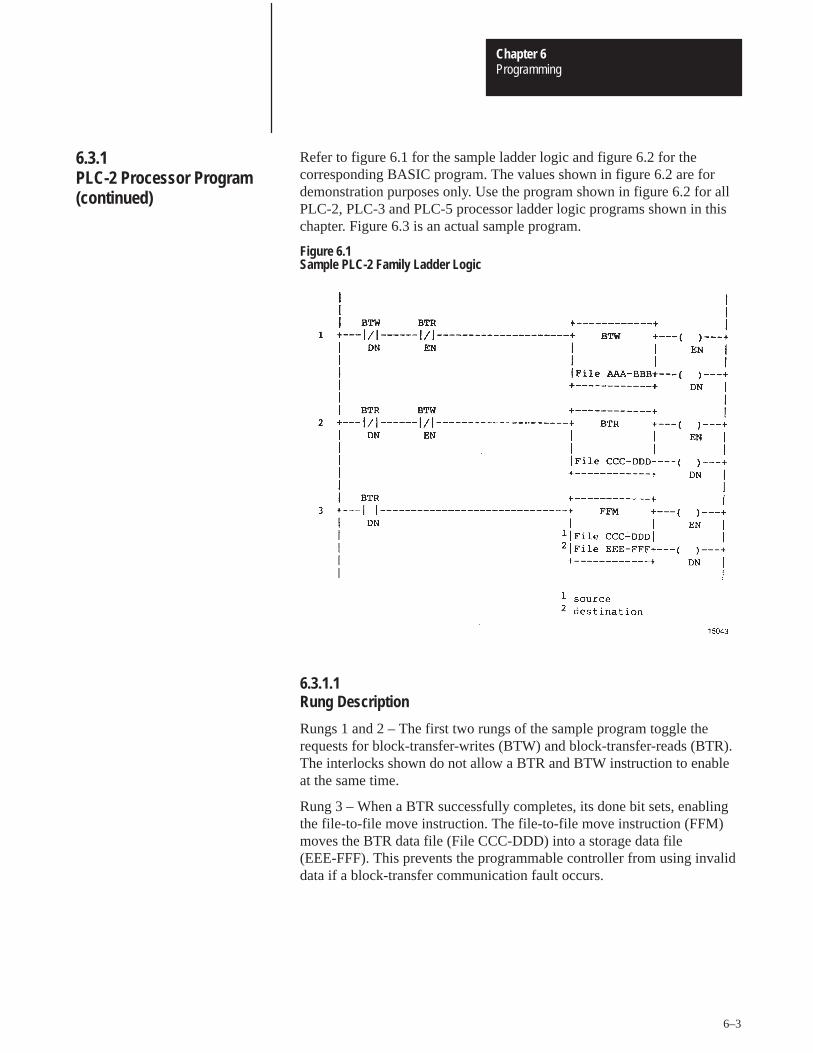
ProgrammingChapter 6
6–3
Refer to figure 6.1 for the sample ladder logic and figure 6.2 for thecorresponding BASIC program. The values shown in figure 6.2 are fordemonstration purposes only. Use the program shown in figure 6.2 for allPLC-2, PLC-3 and PLC-5 processor ladder logic programs shown in thischapter. Figure 6.3 is an actual sample program.
Figure 6.1Sample PLC-2 Family Ladder Logic
6.3.1.1 Rung Description
Rungs 1 and 2 – The first two rungs of the sample program toggle therequests for block-transfer-writes (BTW) and block-transfer-reads (BTR).The interlocks shown do not allow a BTR and BTW instruction to enableat the same time.
Rung 3 – When a BTR successfully completes, its done bit sets, enablingthe file-to-file move instruction. The file-to-file move instruction (FFM)moves the BTR data file (File CCC-DDD) into a storage data file(EEE-FFF). This prevents the programmable controller from using invaliddata if a block-transfer communication fault occurs.
6.3.1 PLC-2 Processor Program(continued)
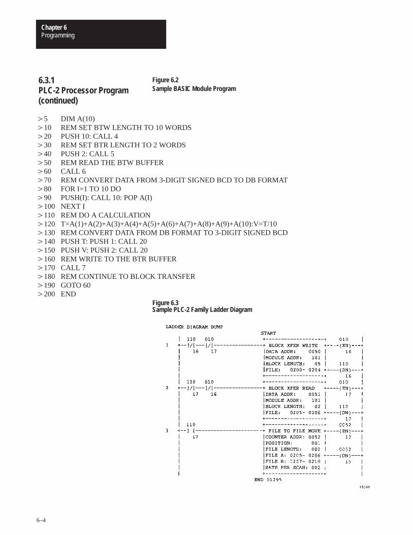
ProgrammingChapter 6
6–4
Figure 6.2Sample BASIC Module Program
�5 DIM A(10) �10 REM SET BTW LENGTH TO 10 WORDS �20 PUSH 10: CALL 4 �30 REM SET BTR LENGTH TO 2 WORDS �40 PUSH 2: CALL 5 �50 REM READ THE BTW BUFFER �60 CALL 6 �70 REM CONVERT DATA FROM 3-DIGIT SIGNED BCD TO DB FORMAT �80 FOR I=1 TO 10 DO �90 PUSH(I): CALL 10: POP A(I) �100 NEXT I �110 REM DO A CALCULATION �120 T=A(1)+A(2)+A(3)+A(4)+A(5)+A(6)+A(7)+A(8)+A(9)+A(10):V=T/10 �130 REM CONVERT DATA FROM DB FORMAT TO 3-DIGIT SIGNED BCD �140 PUSH T: PUSH 1: CALL 20 �150 PUSH V: PUSH 2: CALL 20 �160 REM WRITE TO THE BTR BUFFER �170 CALL 7 �180 REM CONTINUE TO BLOCK TRANSFER �190 GOTO 60 �200 END
Figure 6.3Sample PLC-2 Family Ladder Diagram
6.3.1 PLC-2 Processor Program(continued)
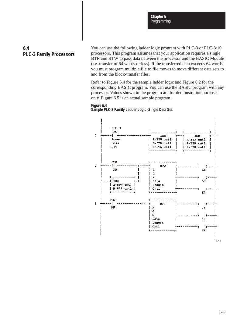
ProgrammingChapter 6
6–5
You can use the following ladder logic program with PLC-3 or PLC-3/10processors. This program assumes that your application requires a singleBTR and BTW to pass data between the processor and the BASIC Module(i.e. transfer of 64 words or less). If the transferred data exceeds 64 wordsyou must program multiple file to file moves to move different data sets toand from the block-transfer files.
Refer to Figure 6.4 for the sample ladder logic and Figure 6.2 for thecorresponding BASIC program. You can use the BASIC program with anyprocessor. Values shown in the program are for demonstration purposesonly. Figure 6.5 is an actual sample program.
Figure 6.4Sample PLC-3 Family Ladder Logic -Single Data Set
6.4 PLC-3 Family Processors
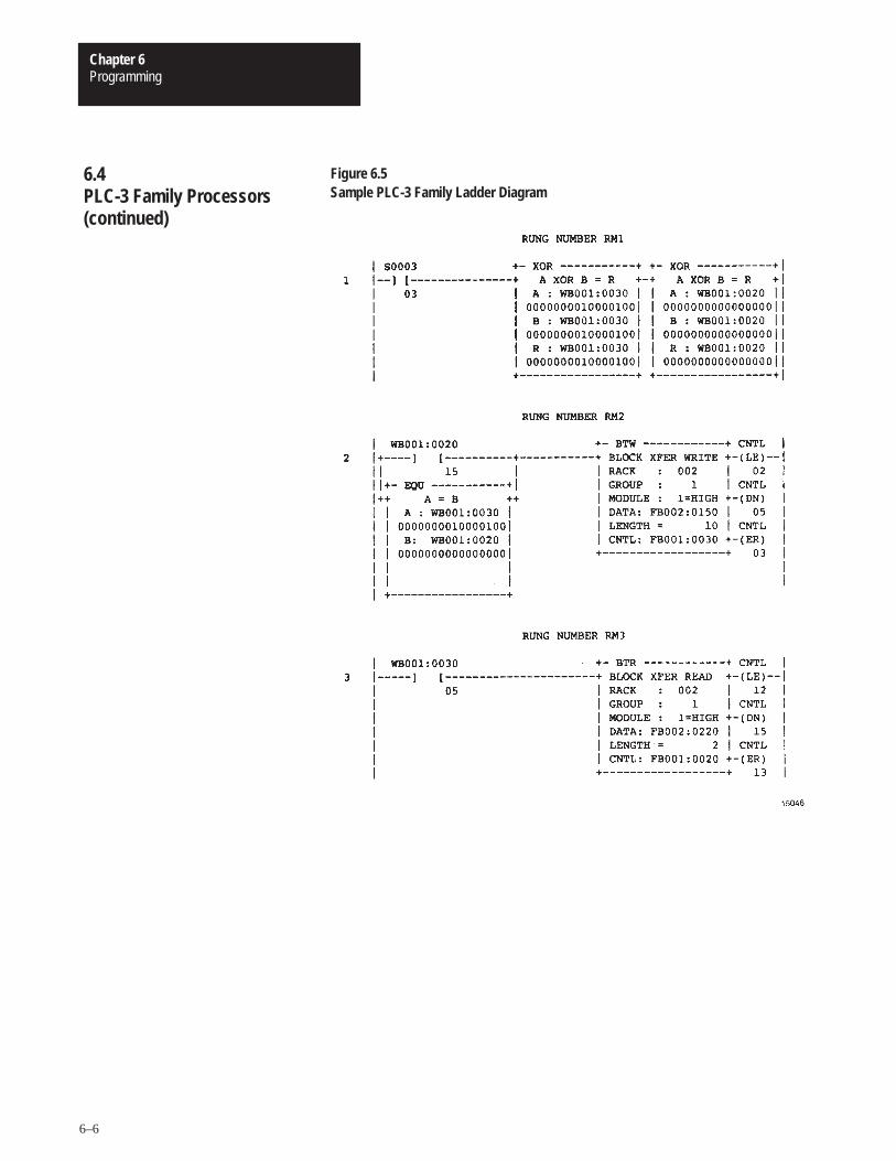
ProgrammingChapter 6
6–6
Figure 6.5Sample PLC-3 Family Ladder Diagram
6.4 PLC-3 Family Processors(continued)
ProgrammingChapter 6
6–7
Rung 1 — Rung one is true only at power-up. It uses status word 3, bit 3(the AC power loss bit of the PLC-3) to zero the control file of both theBTR and BTW.
Rungs 2 and 3 — During normal program execution the BTW and BTRinstructions are alternately executed. The done bits of each instructionenable the next block-transfer instruction. The BTR and BTW control filesmust be different for the next block-transfer to occur.
The equal instruction is used at power-up. At power-up the BTR and BTWcontrol files both equal zero. At power-up the BTW enables andblock-transfers begin.
You can use the following ladder logic program with PLC-5 Familyprocessors. This program assumes that your application requires a singleBTR and BTW to pass data between the processor and the BASIC Module(i.e. transfer of 64 words or less). If the transferred data exceeds 64 wordsyou must program multiple file to file moves to move different data sets toand from the block-transfer files.
The PLC-5 block-transfer program is an alternating read/write program(i.e. at the completion of the BTW the BTR enables. At the completion ofthe BTR the BTW enables). The processor checks data validity beforeaccepting read data and sets one enable bit at a time. Figure 6.6 is a genericsample block-transfer program for a PLC-5 family processor. Figure 6.7 isan actual sample program.
6.4.1 Rung Description for SamplePLC-3 Family Ladder Logic –Single Data Set
6.5 PLC-5 Family Processors
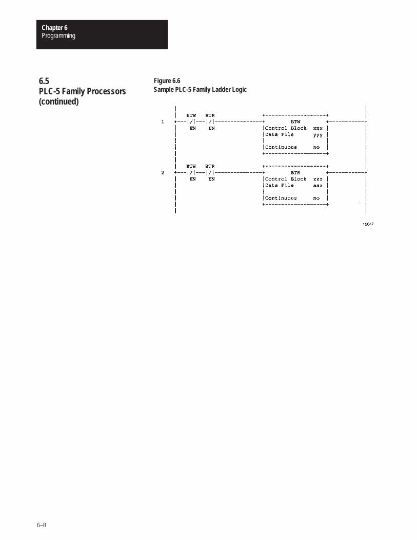
ProgrammingChapter 6
6–8
Figure 6.6Sample PLC-5 Family Ladder Logic
6.5 PLC-5 Family Processors(continued)
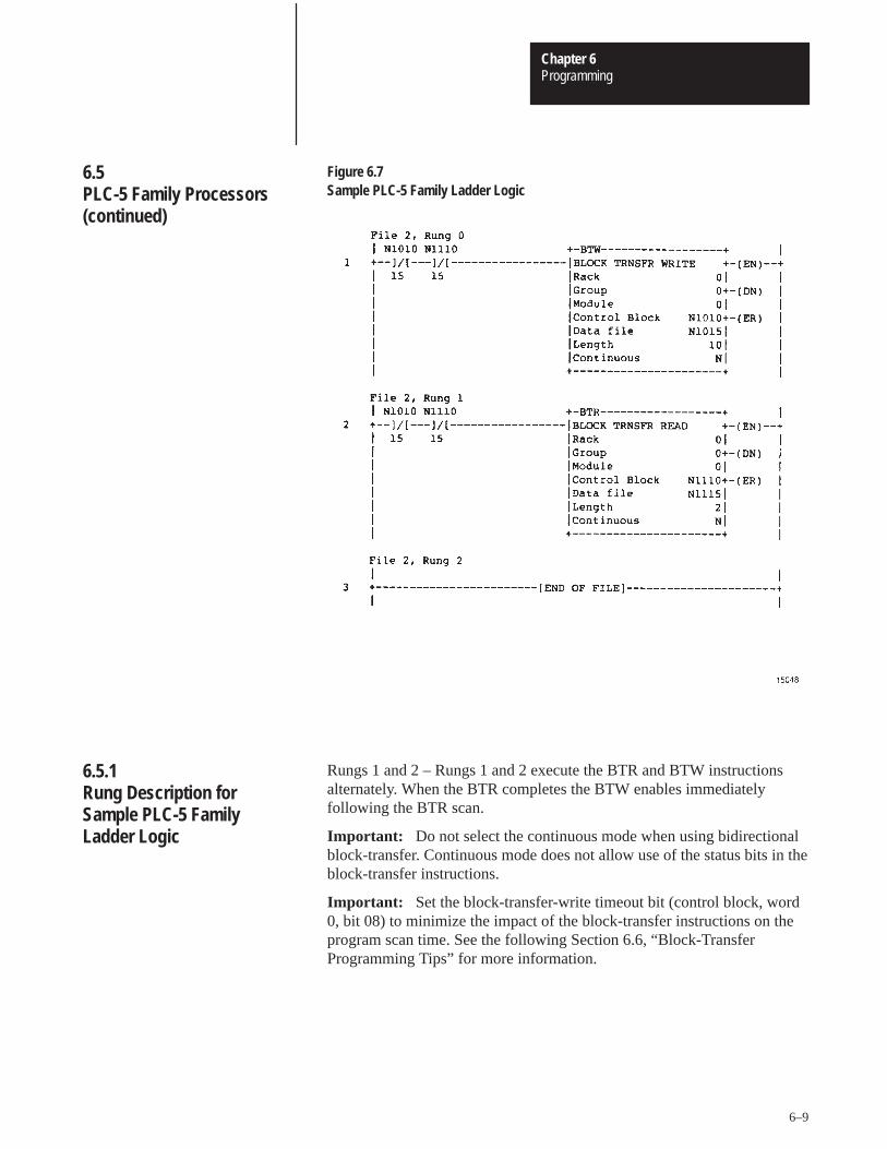
ProgrammingChapter 6
6–9
Figure 6.7Sample PLC-5 Family Ladder Logic
Rungs 1 and 2 – Rungs 1 and 2 execute the BTR and BTW instructionsalternately. When the BTR completes the BTW enables immediatelyfollowing the BTR scan.
Important: Do not select the continuous mode when using bidirectionalblock-transfer. Continuous mode does not allow use of the status bits in theblock-transfer instructions.
Important: Set the block-transfer-write timeout bit (control block, word0, bit 08) to minimize the impact of the block-transfer instructions on theprogram scan time. See the following Section 6.6, “Block-TransferProgramming Tips” for more information.
6.5 PLC-5 Family Processors(continued)
6.5.1 Rung Description for Sample PLC-5 Family Ladder Logic
ProgrammingChapter 6
6–10
1. The block lengths PUSHed for CALLs 4 and 5 must equal thecorresponding lengths on your BTW/BTR instructions in the processor.
2. If a BTW appears first in your ladder logic, put CALLs 3 or 6 first in yourBASIC program. If a BTR appears first in your ladder logic, put CALLs2 or 7 first in your BASIC program.
3. Set the PLC-5 block-transfer-write timeout bit (block-transfer controlblock, word 0 bit 8) to eliminate excessive PLC-5 scan times. When thetimeout bit sets, the processor attempts two DB block-transfers beforegenerating a block-transfer error. The error condition resets the enable bitand restarts the block-transfer in our program example, figure 6.7.
4. If your application requires bidirectional block-transfers, you can useCALL 6 or 3 and CALL 7 or 2 as necessary if:
you use an equal number of each type.
you alternate their use (e.g. CALL 6, CALL 7, CALL 6, CALL7)You can put the calls anywhere in the program. They can occurat any time interval.
5. If your application requires a one way block-transfer (allwrite-block-transfers or all read-block-transfers, use only the associatedCALLs (4, and 3 or 6; 5, and 2 or 7).
6.6. Block-Transfer Programming Tips

Chapter 7
Data Types
This chapter describes the data types and formats used by the BASICModule Data Conversion CALL routines. After reading this chapter youshould be able to interpret and manipulate the data values generated byyour module.
Converted data is exchanged with programmable controllers usingblock-transfers. You can generate the following data types with the BASICModule:
16-bit binary (XXXX)
3-digit, signed, fixed decimal BCD (� XXX.)
4-digit, unsigned, fixed decimal BCD (XXXX.)
4-digit, signed, octal (� XXXX)
6-digit, signed, fixed decimal BCD (� XXXXXX.)
3.3-digit, signed, fixed decimal BCD (� XXX.XXX)
This value requires one word of the processor data table. The data isrepresented by 16 straight binary bits (figure 7.1). The value ranges from 0to 65,535. No sign, overflow or underflow bits are affected or decoded. Ifyou use a value larger than 65,535 or a negative number you get a BADARGUMENT error.
Figure 7.116 Bit Binary Word (4 digit hex)
7.1 Chapter Objectives
7.2 Output Data Types
7.2.1 16-bit Binary (4 Hex Digits)
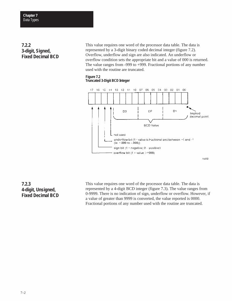
Data TypesChapter 7
7–2
This value requires one word of the processor data table. The data isrepresented by a 3-digit binary coded decimal integer (figure 7.2).Overflow, underflow and sign are also indicated. An underflow oroverflow condition sets the appropriate bit and a value of 000 is returned.The value ranges from -999 to +999. Fractional portions of any numberused with the routine are truncated.
Figure 7.2Truncated 3-Digit BCD Integer
This value requires one word of the processor data table. The data isrepresented by a 4-digit BCD integer (figure 7.3). The value ranges from0-9999. There is no indication of sign, underflow or overflow. However, ifa value of greater than 9999 is converted, the value reported is 0000.Fractional portions of any number used with the routine are truncated.
7.2.2 3-digit, Signed, Fixed Decimal BCD
7.2.3 4-digit, Unsigned, Fixed Decimal BCD
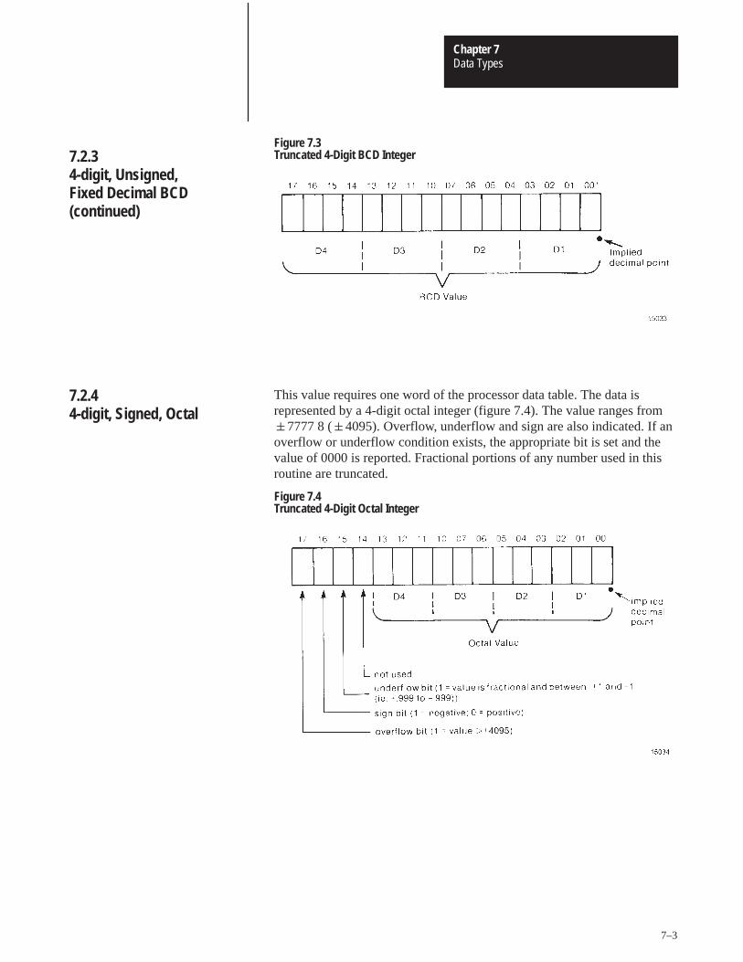
Data TypesChapter 7
7–3
Figure 7.3Truncated 4-Digit BCD Integer
This value requires one word of the processor data table. The data isrepresented by a 4-digit octal integer (figure 7.4). The value ranges from�7777 8 (�4095). Overflow, underflow and sign are also indicated. If anoverflow or underflow condition exists, the appropriate bit is set and thevalue of 0000 is reported. Fractional portions of any number used in thisroutine are truncated.
Figure 7.4Truncated 4-Digit Octal Integer
7.2.3 4-digit, Unsigned, Fixed Decimal BCD(continued)
7.2.4 4-digit, Signed, Octal
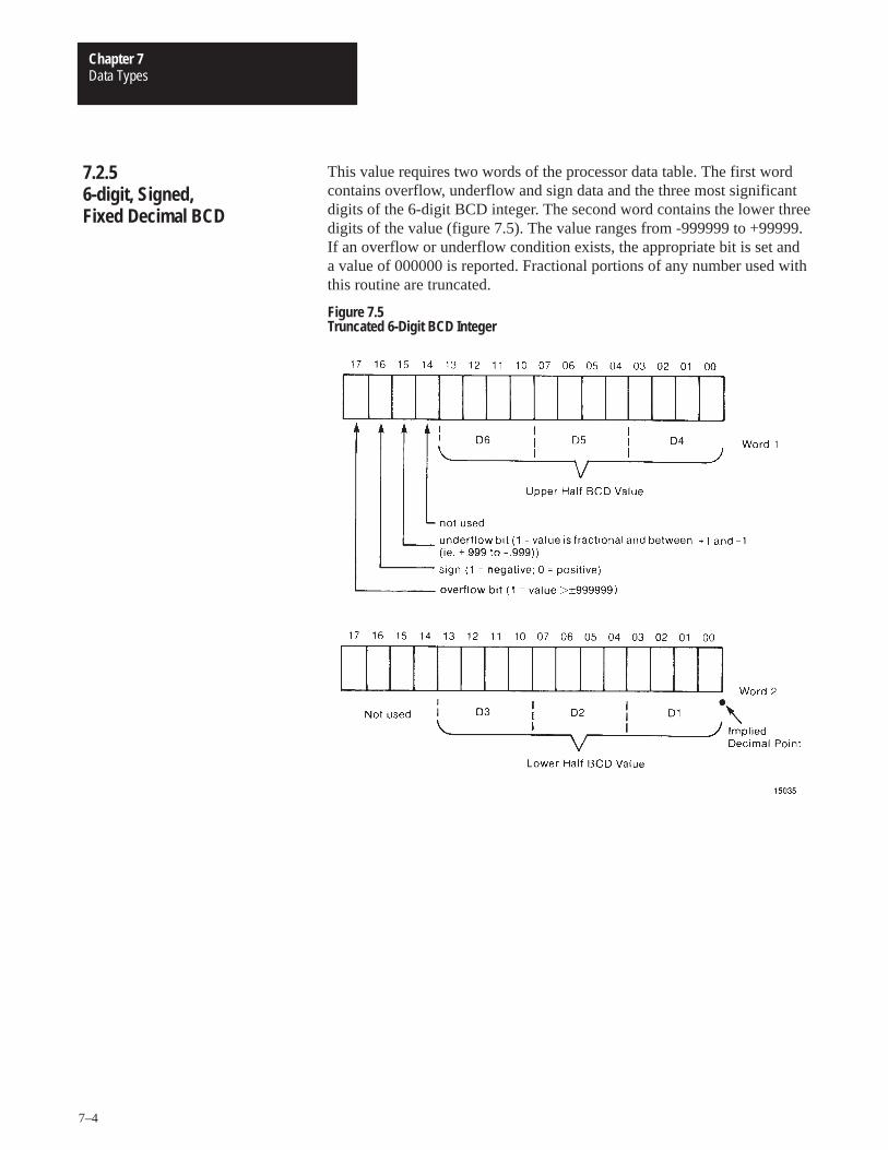
Data TypesChapter 7
7–4
This value requires two words of the processor data table. The first wordcontains overflow, underflow and sign data and the three most significantdigits of the 6-digit BCD integer. The second word contains the lower threedigits of the value (figure 7.5). The value ranges from -999999 to +99999.If an overflow or underflow condition exists, the appropriate bit is set anda value of 000000 is reported. Fractional portions of any number used withthis routine are truncated.
Figure 7.5Truncated 6-Digit BCD Integer
7.2.5 6-digit, Signed, Fixed Decimal BCD
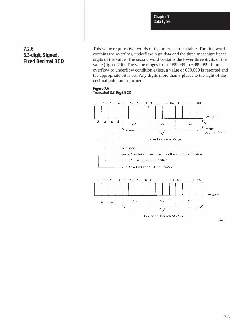
Data TypesChapter 7
7–5
This value requires two words of the processor data table. The first wordcontains the overflow, underflow, sign data and the three most significantdigits of the value. The second word contains the lower three digits of thevalue (figure 7.6). The value ranges from -999.999 to +999.999. If anoverflow or underflow condition exists, a value of 000.000 is reported andthe appropriate bit is set. Any digits more than 3 places to the right of thedecimal point are truncated.
Figure 7.6Truncated 3.3-Digit BCD
7.2.6 3.3-digit, Signed, Fixed Decimal BCD
Data TypesChapter 7
7–6
The BASIC Module interfaces with the PLC-2, PLC-3 and PLC-5 familyprocessors. You can send the following data types to the BASIC Moduletypes to the BASIC Module:
16-bit binary (4 Hex digits) (XXXX)
3-digit, signed, fixed decimal BCD (� XXX.)
4-digit, unsigned, fixed decimal BCD (XXXX.)
4-digit, signed, octal (� XXXX.)
6-digit, signed, fixed decimal BCD (� XXXXXX.)
These data formats are the same as those described under ”Output DataTypes” except for 3.3-digit BCD. Refer to the above descriptions.
The BASIC Module converts the data looking at the sign bit whenapplicable. Refer to the programming manual for your processor for theproper data formats.
7.3 Input Data Types
Chapter 8
Editing A Procedure
After reading this chapter you should be able to make corrections ormodifications to your BASIC programs using the editing featurespresented.
To invoke the edit mode, type [EDIT] and the line number of the RAMprogram line to edit.
For example:
�EDIT 10.
The following features are available in the edit mode.
right/left cursor control
replace a character
insert a character
delete a character
retype a line
Use the following editing commands to make corrections or modificationsto your BASIC program in RAM.
The move feature provides right/left cursor control. The space bar movesthe cursor one space to the right. The [RUB OUT](DELETE) key movesthe cursor one space to the left.
The replace feature allows you to replace the character at the cursorposition. Type the new character over the previous one.
8.2 Chapter Objectives
8.2 Entering the Edit Mode
8.3 Editing Commands/Features
8.3.1 Move
8.3.2 Replace
Editing A ProcedureChapter 8
8–2
Invoke the insert command by typing [CTRL]A. This command insertstext at the cursor position. You must type a second [CTRL]A to terminatethe insert.
Important: When you use insert, all text to the right of the cursordisappears until you type the second [CTRL]A. Total line length is 79characters.
Invoke the delete command by typing [CTRL]D. This command deletesthe character at the cursor position.
Invoke the retype command by typing the [RETURN] key. This featureretypes the line and initializes the cursor to the first character.
Invoke the exit command by typing [CTRL]Q or [CTRL]C.[CTRL]Q exitsthe editor and replaces the old line with the edited line. [CTRL]C exits theeditor with no changes made to the line.
Invoke the renumber command by typing any of the following commands:
REN — begins at the start of the program and continues through the endof the program. The new line numbers begin at 10 and increment by 10.
REN[NUM] — begins at the start of the program and continues throughthe end of the program. The new line numbers begin at 10 andincrement by NUM.
8.3.3 Insert
8.3.4 Delete
8.3.5 Retype
8.3.6 Exits
8.3.7 Renumber
Editing A ProcedureChapter 8
8–3
REN[NUM1],[NUM2] — begins at the start of the program andcontinues through the end of the program. The new line numbers beginwith NUM1 and increment by NUM2.
REN[NUM1],[NUM2],[NUM3] — begins at NUM2 and continuesthrough the end of the program. The new line numbers begin withNUM1 and increment by NUM3.
Important: The renumber command updates the destination of GOSUB,GOTO, ON ERR, ON TIME and ON GOTO statements.
If the target line number does not exist, or if there is insufficient memoryto complete the task, no lines are changed and the message “RENUMBERERROR” appears on the console screen.
Important: Because the renumber command uses the same RAM forrenumbering as it does for variable and program storage, available RAMmay be insufficient in large programs. We recommend that you renumberyour program periodically during development. Do not wait until it iscompleted.
8.3.7 Renumber (continued)
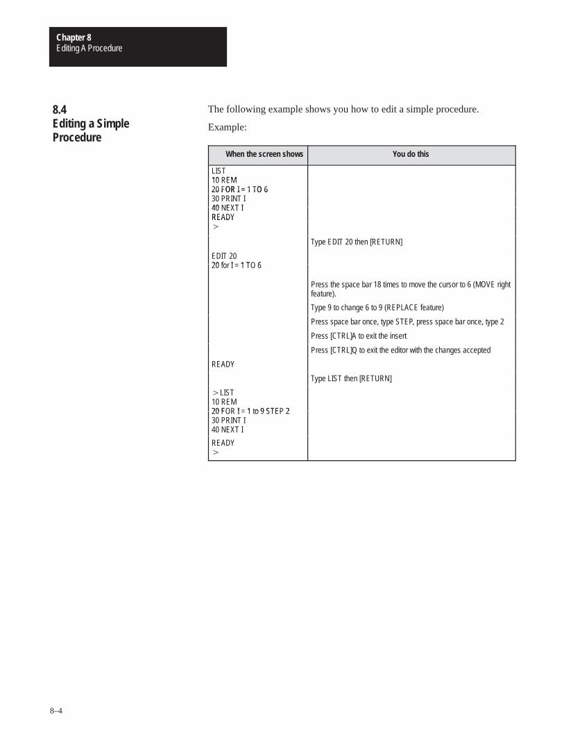
Editing A ProcedureChapter 8
8–4
The following example shows you how to edit a simple procedure.
Example:
When the screen shows You do this
LIST10 EM10 REM20 FOR I = 1 TO 620 FOR I = 1 TO 630 PRINT I40 E T I40 NEXT IREADYREADY�
Type EDIT 20 then [RETURN]
EDIT 2020 fo I 1 T 620 for I = 1 TO 6
Press the space bar 18 times to move the cursor to 6 (MOVE rightfeature).
Type 9 to change 6 to 9 (REPLACE feature)
Press space bar once, type STEP, press space bar once, type 2
Press [CTRL]A to exit the insert
Press [CTRL]Q to exit the editor with the changes accepted
READY
Type LIST then [RETURN]
�LIST10 REM20 F I 1 o 9 STE 220 FOR I = 1 to 9 STEP 230 PRINT I40 NEXT I40 E T I
READY�
8.4 Editing a Simple Procedure
Chapter 9
Error Messages and Anomalies
After reading this chapter you should be familiar with the module’s errormessages and anomalies.
When BASIC is in the RUN mode the format of the ERROR messages isas follows:
ERROR: XXX – IN LINE YYY
YYY BASIC STATEMENT X
Where XXX is the ERROR TYPE and YYY is the line number of theprogram in which the error occurred. A specific example is:
ERROR: BAD SYNTAX – IN LINE 10
10 PRINT 34*21* X
The X shows approximately where the ERROR occurred in the linenumber. The specific location of the X may be off by one or two charactersor expressions depending on the type of error and where the error occurredin the program. If an ERROR occurs in the COMMAND MODE only theERROR TYPE is printed out, not the line number. The ERROR TYPESare as follows:
A-STACK — An A-STACK (ARGUMENT STACK) error occurs whenthe argument stack pointer is forced “out of bounds”. An “out of bounds”condition occurs if:
you overflow the argument stack by PUSHing too many expressionsonto the stack.
you attempt to POP data off the stack when no data is present.
ARITH. OVERFLOW — An ARITH. OVERFLOW occurs when anarithmetic operation exceeds the upper limit of a module floating pointnumber. The largest floating point number in the BASIC Module is+/–.99999999E+127. For example, 1E+70*1E+70 causes an ARITH.OVERFLOW error.
9.1 Chapter Objectives
9.2 Error Messages from BASIC
Error Messages and AnomaliesChapter 9
9–2
ARITH. UNDERFLOW — An ARITH. UNDERFLOW occurs when anarithmetic operation exceeds the lower limit of a module floating pointnumber. The smallest floating point number in the BASIC Module is+/–lE–127. For example, 1E–80/1E+80 causes an ARITH. UNDERFLOWerror.
ARRAY SIZE — An ARRAY SIZE error occurs if an array is dimensionedby a DIM statement and you attempt to access a variable that is outside ofthe dimensioned bounds.
Example:
�DIM A(10) �Print A(11)
ERROR: ARRAY SIZE READY
BAD ARGUMENT — A BAD ARGUMENT error occurs when theargument of an operator is not within the limits of the operator. Forexample, SQR(–12) generates a BAD ARGUMENT error because thevalue of the SQR argument is limited to positive numbers.
BAD SYNTAX — A BAD SYNTAX error occurs when either an invalidBASIC Module command, statement or operator is entered and BASICcannot process the entry. Check to make sure that all entries are correct.
C-STACK — A C-STACK (CONTROL STACK) error occurs if:
the control stack pointer is forced “out of bounds”.
you attempt to use more control stack than is available in the module.
you execute a RETURN before a GOSUB, a WHILE or UNTIL beforea DO, or a NEXT before a FOR.
you jump out of loop structures such as DO WHILE.
CAN’T CONTINUE — A CAN’T CONTINUE error appears if:
you edit the program after halting execution and then enter the CONTcommand.
you enter CTRL C while in a call routine.
You can halt program execution by either entering CTRL C or byexecuting a STOP statement. Normally, program execution continues afterentering the CONT command. You must enter CTRL C during programexecution or you must execute a STOP statement before the CONTcommand can work.
DIVIDE BY ZERO — A DIVIDE BY ZERO error occurs if you attemptto divide by zero (12/0).
9.2 Error Messages from BASIC (continued)
Error Messages and AnomaliesChapter 9
9–3
EXTRA IGNORED — Error occurs when an INPUT statement requiringnumeric data, receives numeric data followed by letters. Letters areignored. Error also occurs from CALL 61.
MEMORY ALLOCATION — A MEMORY ALLOCATION error occurswhen:
user memory (RAM) is full.
BASIC cannot determine memory bounds because the system controlvalue MTOP is altered.
RAM contains an incomplete program file.
you attempt to access STRINGS that are “outside” the defined stringlimits.
NO DATA — A NO DATA message occurs if a READ STATEMENT isexecuted and no DATA STATEMENT exists or all DATA was read and aRESTORE instruction was not executed. The message ERROR: NO DATA– IN LINE XXX is printed to the console device.
PROGRAMMING — If an error occurs while the BASIC Module isprogramming an EPROM, a PROGRAMMING error occurs. An errorduring programming destroys the EPROM file structure. You cannot saveany more programs on that particular EPROM once a PROGRAMMINGerror occurs. If the EPROM size is exceeded, the previously storedprogram may be partially altered.
Your module generates the following messages when an error occurs whiletrying to execute a CALL routine.
NEGATIVE VALUES NOT VALID — This error occurs when youattempt to convert a negative number with CALL 21 or 27.
CHECKSUM ERROR FROM RECORDER — This error occurs whenbad data is received from the tape while executing CALLS 33, 34 or 39.You should check for correct cable connections and baud rate. Also checkyour tape cartridge.
9.2 Error Messages from BASIC (continued)
9.3 Error Messages from CALL Routines
9.3.1 Data Conversion CALL Error Messages
9.3.2 Peripheral Port Support CALL Error Messages
Error Messages and AnomaliesChapter 9
9–4
IN ROM — The IN ROM message displays if you attempt to load a ROMprogram to tape with CALL 32 or 38. You should transfer the ROMprogram to RAM and then load the program to tape.
INVALID INPUT DATA — This error occurs when you enter an invalidvalue when using CALL 30.
INVALID VALUE PUSHED — This error occurs when you enter a valueother then 0, 1 or 2 when using CALL 37.
LOAD/SAVE ABORT — This error occurs when you execute a CTRL Cfrom any tape CALL (32, 33, 34, 38 or 39).
NO BASIC PROGRAM EXIST — This error occurs when the BASICModule is in RAM mode with no program in RAM and you attempt toexecute a CALL 32 or 38. You should enter a program in RAM or XFER aROM program to RAM prior to loading to tape with CALL 32 or 38.
INSUFFICIENT NUMBER OF STRING CHARACTERS ALLOCATED— This error occurs if you attempt to execute a CALL 43, 45 or 52 and astring length of 18, 8 or 9, respectively, is not allocated during stringallocation.
INVALID DATE/TIME PUSHED — This error occurs when you enter aninvalid value for the date and/or time when using CALL 40 and 41.
NUMBER BYTES/STRING EXCEED 254 — This error occurs whenusing CALL 43, 45 or 52 and the STRING X,X command allocates morecharacters per string than is allowed.
Example:
10 STRING 1000,300
INVALID NUMBER PUSHED — This error occurs when you pushan invalid string value or day of week value using CALL 42, 43 and52.
9.3.2 Peripheral Port Support CALL Error Messages(continued)
9.3.3 Wall Clock CALL ErrorMessages
Error Messages and AnomaliesChapter 9
9–5
STRING# NOT ALLOCATED — This error occurs if you attempt toaccess a string that is outside the allocated string memory when usingCALLs 60, 61, 64, 65, 66, 67, or 68.
Example:
�10 STRING 100,9 REM 10 STRINGS ALLOCATED$(0)–$(9)
�20 PUSH 5,12 REM REPEAT CHAR 5 TIMESIN$(12)
�30 CALL 60 �RUN
ERROR — STRING # NOT ALLOCATED
Error occurs because STRING 12 is outside the area reserved for strings.
#BYTES/STRING EXCEED 254 — This error occurs if the STRING X,Xcommand allocates more characters per string than is allowed using CALL62.
Example:
�10 STRING 1000,300
INSUFFICIENT NUMBER OF STRING CHARACTERS This erroroccurs if you do not use the required minimum string lengths when usingCALL 62.
BAD # PUSHED — This error occurs if the string position pointer is zero(invalid position) using CALL 66.
INSUFFICIENT STRING SIZE — This error occurs if the resulting stringcannot hold all required characters when using CALLs 61 or 66.
Example:
�10 STRING 100,9 REM MAX OF 9 CHR’S/STRING�20 $(0)=“01234567” �30 $(1)=“890”
If you attempt to insert or concatenate, an error occurs because theresulting string requires 11 characters.
9.3.4 String Support CALL Error Messages
Error Messages and AnomaliesChapter 9
9–6
BAD POSITION— This error occurs if you attempt to access a stringposition that is beyond the declared length of the string when using CALL66.
Example:
�10 STRING 100,9 �20 $(0)=“1234” �30 $(1)=“56” �40 PUSH 6 REM INVALID POSITION OF $(0) �50 PUSH 1 REM $(1) �60 PUSH 0 REM $(0) �70 CALL 66 REM INSERT $(1) INTO $(0) @ POS 6
BAD POSITION error results because position 6 is outside of the declaredstring.
EXTRA IGNORED — This error occurs when the resulting string cannothold all the characters when using CALL 61. Similar to insufficient stringsize error. Extra characters are lost.
Input — An input statement requiring numeric data, received numeric datafollowed by letters. The letters are ignored.
Example:
Input A
Entering 1.23AB causes this error message. The program continues to run.
INVALID MTOP ADDRESS ENTERED — This error occurs when youselect an invalid RAM location for a new MTOP value when using CALL77.
PROGRAM NOT FOUND — This error occurs if a program numberhigher than 255 is PUSHed when using CALL 71 or 72 or if the program isnot found.
9.3.4 String Support CALL Error Messages (continued)
9.3.5 Memory Support CALL Error Messages
Error Messages and AnomaliesChapter 9
9–7
INVALID BAUD RATE ENTERED — This error occurs when a baud rateother than 300, 600, 1200, 2400, 4800, 9600 or 19.2K bps is PUSHedusing CALL 78.
INCOMPLETE ROM PROGRAM FOUND — This error occurs whenCALL 81 detects an incomplete program in the EPROM. You can burn noadditional programs onto this PROM. All earlier programs are stillaccessible.
NO PROGRAM FOUND BUT THE PROM IS NOT BLANK —�Thiserror occurs if miscellaneous data is found on a “blank” PROM usingCALL 81. You should clear the PROM before using it.
NEGATIVE VALUE NOT VALID —�This error occurs if you attempt toconvert a negative number using CALL 21.
Anomalies are deviations from the normal. Anomalies in the BASICModule can occur as the module compacts or tokenizes the BASICprogram. The known anomalies and cautions are as follows:
1. When using the variable H after a line number, put a space between theline number and the H. If you do not, the program assumes that the linenumber is a HEX number.
Examples:
Wrong Right
�20H=10 �20 H=10
�LIST �LIST
32 =10 20 H=10
9.3.6 Miscellaneous CALL Error Messages
9.4 Anomalies
Error Messages and AnomaliesChapter 9
9–8
2. When using the variable I before an ELSE statement, put a space betweenthe I and the ELSE statement. If you do not, the program assumes thatthe IE portion of IELSE is the special function operator IE.
This error may or may not yield a BAD SYNTAX — IN LINE XXXerror message, depending on the particular program in which it isused.
Examples:
Wrong
�20 IF I �10 THEN PRINT IELSE 100 �LIST 20 IF I �10 THEN PRINT I ELSE 100
Right
�20 IF I�10 THEN PRINT I ELSE 100 �LIST 20 IF I �10 THEN PRINT I ELSE 100
3. Do not place a space character inside the ASC() operator. A statementlike PRINT ASC() yields a BAD SYNTAX ERROR. You can put spacesin strings, however, allowing the following statement to work properly:
LET $(1) �“HELLO, HOW ARE YOU”
ASC() yields an error because the module eliminates all spaces whena line is processed. ASC() is stored as ASC() and the moduleinterprets this as an error.
4. Do not use the following one letter variables: B, F, R. Unpredictableoperation could result.
5. Do not use the following two letter variables: CR, DO, lE, IF, IP, ON, PI,SP, TO, UI and UO.
6. When using an INPUT statement to enter data you must be sure to entervalid data. If you enter invalid data you see the prompt “TRY AGAIN”.This disrupts the screen layout.
7. SQR(M–M2) gives a bad argument if M=O.
8. ONTIME does not interrupt CALL routines, INPUT statements orPRINT# statements waiting for handshaking (XON, CTS, DCD) tobecome true. ONTIME is a polling mechanism which is checked aftereach line of BASIC is completed. End of line is either a (CR) or (:).
9.4 Anomalies (continued)
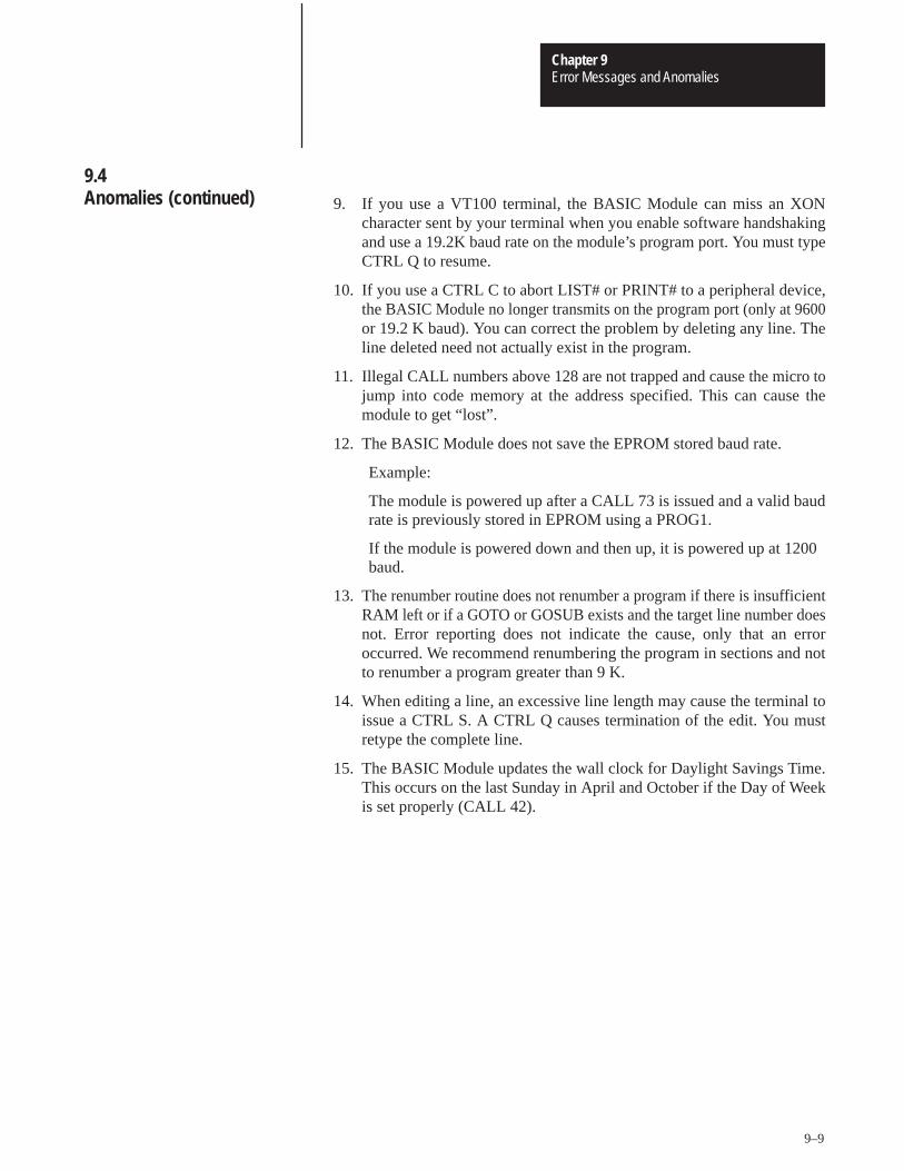
Error Messages and AnomaliesChapter 9
9–9
9. If you use a VT100 terminal, the BASIC Module can miss an XONcharacter sent by your terminal when you enable software handshakingand use a 19.2K baud rate on the module’s program port. You must typeCTRL Q to resume.
10. If you use a CTRL C to abort LIST# or PRINT# to a peripheral device,the BASIC Module no longer transmits on the program port (only at 9600or 19.2 K baud). You can correct the problem by deleting any line. Theline deleted need not actually exist in the program.
11. Illegal CALL numbers above 128 are not trapped and cause the micro tojump into code memory at the address specified. This can cause themodule to get “lost”.
12. The BASIC Module does not save the EPROM stored baud rate.
Example:
The module is powered up after a CALL 73 is issued and a valid baudrate is previously stored in EPROM using a PROG1.
If the module is powered down and then up, it is powered up at 1200baud.
13. The renumber routine does not renumber a program if there is insufficientRAM left or if a GOTO or GOSUB exists and the target line number doesnot. Error reporting does not indicate the cause, only that an erroroccurred. We recommend renumbering the program in sections and notto renumber a program greater than 9 K.
14. When editing a line, an excessive line length may cause the terminal toissue a CTRL S. A CTRL Q causes termination of the edit. You mustretype the complete line.
15. The BASIC Module updates the wall clock for Daylight Savings Time.This occurs on the last Sunday in April and October if the Day of Weekis set properly (CALL 42).
9.4 Anomalies (continued)
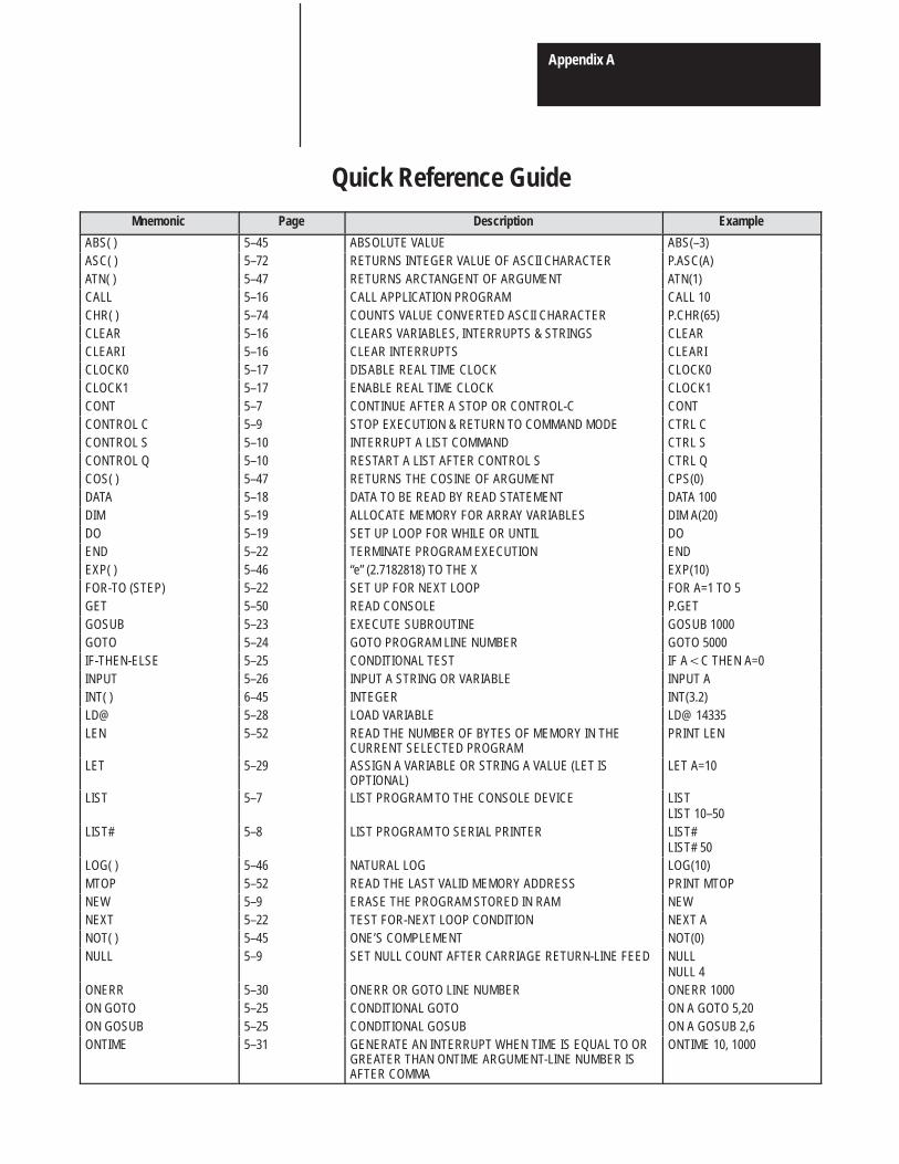
Appendix A
Quick Reference GuideMnemonic Page Description Example
ABS( ) 5–45 ABSOLUTE VALUE ABS(–3)ASC( ) 5–72 RETURNS INTEGER VALUE OF ASCII CHARACTER P.ASC(A)ATN( ) 5–47 RETURNS ARCTANGENT OF ARGUMENT ATN(1)CALL 5–16 CALL APPLICATION PROGRAM CALL 10CHR( ) 5–74 COUNTS VALUE CONVERTED ASCII CHARACTER P.CHR(65)CLEAR 5–16 CLEARS VARIABLES, INTERRUPTS & STRINGS CLEARCLEARI 5–16 CLEAR INTERRUPTS CLEARICLOCK0 5–17 DISABLE REAL TIME CLOCK CLOCK0CLOCK1 5–17 ENABLE REAL TIME CLOCK CLOCK1CONT 5–7 CONTINUE AFTER A STOP OR CONTROL-C CONTCONTROL C 5–9 STOP EXECUTION & RETURN TO COMMAND MODE CTRL CCONTROL S 5–10 INTERRUPT A LIST COMMAND CTRL SCONTROL Q 5–10 RESTART A LIST AFTER CONTROL S CTRL QCOS( ) 5–47 RETURNS THE COSINE OF ARGUMENT CPS(0)DATA 5–18 DATA TO BE READ BY READ STATEMENT DATA 100DIM 5–19 ALLOCATE MEMORY FOR ARRAY VARIABLES DIM A(20)DO 5–19 SET UP LOOP FOR WHILE OR UNTIL DOEND 5–22 TERMINATE PROGRAM EXECUTION ENDEXP( ) 5–46 “e” (2.7182818) TO THE X EXP(10)FOR-TO (STEP) 5–22 SET UP FOR NEXT LOOP FOR A=1 TO 5GET 5–50 READ CONSOLE P.GETGOSUB 5–23 EXECUTE SUBROUTINE GOSUB 1000GOTO 5–24 GOTO PROGRAM LINE NUMBER GOTO 5000IF-THEN-ELSE 5–25 CONDITIONAL TEST IF A�C THEN A=0INPUT 5–26 INPUT A STRING OR VARIABLE INPUT AINT( ) 6–45 INTEGER INT(3.2)LD@ 5–28 LOAD VARIABLE LD@ 14335LEN 5–52 READ THE NUMBER OF BYTES OF MEMORY IN THE
CURRENT SELECTED PROGRAMPRINT LEN
LET 5–29 ASSIGN A VARIABLE OR STRING A VALUE (LET ISOPTIONAL)
LET A=10
LIST 5–7 LIST PROGRAM TO THE CONSOLE DEVICE LISTLIST 10–50
LIST# 5–8 LIST PROGRAM TO SERIAL PRINTER LIST#LIST# 50
LOG( ) 5–46 NATURAL LOG LOG(10)MTOP 5–52 READ THE LAST VALID MEMORY ADDRESS PRINT MTOPNEW 5–9 ERASE THE PROGRAM STORED IN RAM NEWNEXT 5–22 TEST FOR-NEXT LOOP CONDITION NEXT ANOT( ) 5–45 ONE’S COMPLEMENT NOT(0)NULL 5–9 SET NULL COUNT AFTER CARRIAGE RETURN-LINE FEED NULL
NULL 4ONERR 5–30 ONERR OR GOTO LINE NUMBER ONERR 1000ON GOTO 5–25 CONDITIONAL GOTO ON A GOTO 5,20ON GOSUB 5–25 CONDITIONAL GOSUB ON A GOSUB 2,6ONTIME 5–31 GENERATE AN INTERRUPT WHEN TIME IS EQUAL TO OR
GREATER THAN ONTIME ARGUMENT-LINE NUMBER ISAFTER COMMA
ONTIME 10, 1000
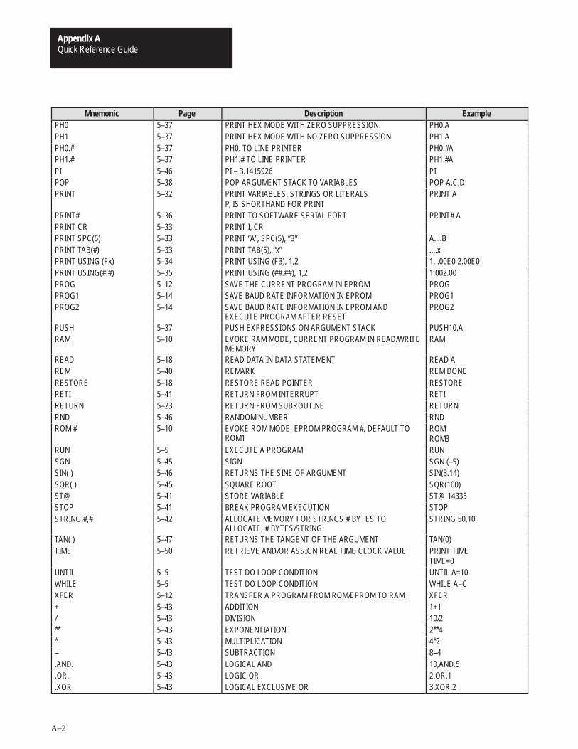
Quick Reference GuideAppendix A
A–2
Mnemonic Page Description ExamplePH0 5–37 PRINT HEX MODE WITH ZERO SUPPRESSION PH0.APH1 5–37 PRINT HEX MODE WITH NO ZERO SUPPRESSION PH1.APH0.# 5–37 PH0. TO LINE PRINTER PH0.#APH1.# 5–37 PH1.# TO LINE PRINTER PH1.#API 5–46 PI – 3.1415926 PIPOP 5–38 POP ARGUMENT STACK TO VARIABLES POP A,C,DPRINT 5–32 PRINT VARIABLES, STRINGS OR LITERALS
P, IS SHORTHAND FOR PRINTPRINT A
PRINT# 5–36 PRINT TO SOFTWARE SERIAL PORT PRINT# APRINT CR 5–33 PRINT I, CRPRINT SPC(5) 5–33 PRINT “A”, SPC(5), “B” A....BPRINT TAB(#) 5–33 PRINT TAB(5), “x” ....xPRINT USING (Fx) 5–34 PRINT USING (F3), 1,2 1. .00E0 2.00E0PRINT USING(#.#) 5–35 PRINT USING (##.##), 1,2 1.002.00PROG 5–12 SAVE THE CURRENT PROGRAM IN EPROM PROGPROG1 5–14 SAVE BAUD RATE INFORMATION IN EPROM PROG1PROG2 5–14 SAVE BAUD RATE INFORMATION IN EPROM AND
EXECUTE PROGRAM AFTER RESETPROG2
PUSH 5–37 PUSH EXPRESSIONS ON ARGUMENT STACK PUSH10,ARAM 5–10 EVOKE RAM MODE, CURRENT PROGRAM IN READ/WRITE
MEMORYRAM
READ 5–18 READ DATA IN DATA STATEMENT READ AREM 5–40 REMARK REM DONERESTORE 5–18 RESTORE READ POINTER RESTORERETI 5–41 RETURN FROM INTERRUPT RETIRETURN 5–23 RETURN FROM SUBROUTINE RETURNRND 5–46 RANDOM NUMBER RNDROM # 5–10 EVOKE ROM MODE, EPROM PROGRAM #, DEFAULT TO
ROM1ROMROM3
RUN 5–5 EXECUTE A PROGRAM RUNSGN 5–45 SIGN SGN (–5)SIN( ) 5–46 RETURNS THE SINE OF ARGUMENT SIN(3.14)SQR( ) 5–45 SQUARE ROOT SQR(100)ST@ 5–41 STORE VARIABLE ST@ 14335STOP 5–41 BREAK PROGRAM EXECUTION STOPSTRING #,# 5–42 ALLOCATE MEMORY FOR STRINGS # BYTES TO
ALLOCATE, # BYTES/STRINGSTRING 50,10
TAN( ) 5–47 RETURNS THE TANGENT OF THE ARGUMENT TAN(0)TIME 5–50 RETRIEVE AND/OR ASSIGN REAL TIME CLOCK VALUE PRINT TIME
TIME=0UNTIL 5–5 TEST DO LOOP CONDITION UNTIL A=10WHILE 5–5 TEST DO LOOP CONDITION WHILE A=CXFER 5–12 TRANSFER A PROGRAM FROM ROM/EPROM TO RAM XFER+ 5–43 ADDITION 1+1/ 5–43 DIVISION 10/2** 5–43 EXPONENTIATION 2**4* 5–43 MULTIPLICATION 4*2– 5–43 SUBTRACTION 8–4.AND. 5–43 LOGICAL AND 10,AND.5.OR. 5–43 LOGIC OR 2.OR.1.XOR. 5–43 LOGICAL EXCLUSIVE OR 3.XOR.2
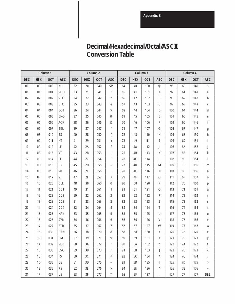
Appendix B
Decimal/Hexadecimal/Octal/ASCIIConversion Table
Column 1 Column 2 Column 3 Column 4
DEC HEX OCT ASC DEC HEX OCT ASC DEC HEX OCT ASC DEC HEX OCT ASC
00 00 000 NUL 32 20 040 SP 64 40 100 @ 96 60 140 \
01 01 001 SOH 33 21 041 ! 65 41 101 A 97 61 141 a
02 02 002 STX 34 22 042 ″ 66 42 102 B 98 62 142 b
03 03 003 ETX 35 23 043 # 67 43 103 C 99 63 143 c
04 04 004 EOT 36 24 044 $ 68 44 104 D 100 64 144 d
05 05 005 ENQ 37 25 045 % 69 45 105 E 101 65 145 e
06 06 006 ACK 38 26 046 & 70 46 106 F 102 66 146 f
07 07 007 BEL 39 27 047 � 71 47 107 G 103 67 147 g
08 08 010 BS 40 28 050 ( 72 48 110 H 104 68 150 h
09 09 011 HT 41 29 051 ) 73 49 111 I 105 69 151 i
10 0A 012 LF 42 2A 052 * 74 4A 112 J 106 6A 152 j
11 0B 013 VT 43 2B 053 + 75 4B 113 K 107 6B 154 k
12 0C 014 FF 44 2C 054 ’ 76 4C 114 L 108 6C 154 l
13 0D 015 CR 45 2D 055 – 77 4D 115 M 109 ED 155 m
14 0E 016 S0 46 2E 056 . 78 4E 116 N 110 6E 156 n
15 0F 017 SI 47 2F 057 / 79 4F 117 O 111 6F 157 o
16 10 020 DLE 48 30 060 0 80 50 120 P 112 70 160 p
17 11 021 DC1 49 31 061 1 81 51 121 Q 113 71 161 q
18 12 022 DC2 50 32 062 2 82 52 122 R 114 72 162 r
19 13 023 DC3 51 33 063 3 83 53 123 S 115 73 163 s
20 14 024 DC4 52 34 064 4 84 54 124 T 116 74 164 t
21 15 025 NAK 53 35 065 5 85 55 125 U 117 75 165 u
22 16 026 SYN 54 36 066 6 86 56 126 V 118 76 166 v
23 17 027 ETB 55 37 067 7 87 57 127 W 119 77 167 w
24 18 030 CAN 56 38 070 8 88 58 130 X 120 78 170 x
25 19 031 EM 57 39 071 9 89 59 131 Y 121 79 171 y
26 1A 032 SUB 58 3A 072 : 90 5A 132 Z 122 7A 172 z
27 1B 033 ESC 59 3B 073 ; 91 5B 133 [ 123 7B 173 {
28 1C 034 FS 60 3C 074 < 92 5C 134 \ 124 7C 174 .
29 1D 035 GS 61 3D 075 = 93 5D 135 ] 125 7D 175 }
30 1E 036 RS 62 3E 076 > 94 5E 136 ^ 126 7E 176 ~
31 1F 037 US 63 3F 077 ? 95 5F 137 _ 127 7F 177 DEL

2
Appendix C
Basic Module Programming Hints
These programming hints can help you to properly program your moduleto increase module performance.
1. Always define strings first.
2. Always dimension arrays after defining strings.
3. Define the most used variables first. You can use 0 values until you assignreal values.
4. When doing math, save intermediate values rather than recalculate.
5. Place the most used subroutines near the beginning of the program.
6. Straight through code executes faster, but uses more memory.
7. Put multiple statements on a line, after the program has been debugged.
8. Comments use space and slow program execution. After the program isdebugged save a fully commented copy on tape or spare ERROM andremove comments.
BASIC Module Programming Hints

Publication 1771–6.5.34 July 1987
Allen-Bradley, a Rockwell Automation Business, has been helping its customers improveproductivity and quality for more than 90 years. We design, manufacture and support a broadrange of automation products worldwide. They include logic processors, power and motioncontrol devices, operator interfaces, sensors and a variety of software. Rockwell is one of theworld’s leading technology companies.
Worldwide representation.Argentina • Australia • Austria • Bahrain • Belgium • Brazil • Bulgaria • Canada • Chile • China, PRC • Colombia • Costa Rica • Croatia • Cyprus • Czech Republic • Denmark •Ecuador • Egypt • El Salvador • Finland • France • Germany • Greece • Guatemala • Honduras • Hong Kong • Hungary • Iceland • India • Indonesia • Ireland • Israel • Italy •Jamaica • Japan • Jordan • Korea • Kuwait • Lebanon • Malaysia • Mexico • Netherlands • New Zealand • Norway • Pakistan • Peru • Philippines • Poland • Portugal • PuertoRico • Qatar • Romania • Russia–CIS • Saudi Arabia • Singapore • Slovakia • Slovenia • South Africa, Republic • Spain • Sweden • Switzerland • Taiwan • Thailand • Turkey •United Arab Emirates • United Kingdom • United States • Uruguay • Venezuela • Yugoslavia
Allen-Bradley Headquarters, 1201 South Second Street, Milwaukee, WI 53204 USA, Tel: (1) 414 382-2000 Fax: (1) 414 382-4444
Publication 1771–6.5.34 July 1987 PN 955101–26Copyright 1987 Allen-Bradley Company, Inc. Printed in USA