Embed Size (px)
Citation preview

User
Manual
Analog InputSystem
(Cat. Nos. 1771-IF Series Band 1771-E1, E2, E3))
Allen�Bradley

Introduction 1�1. . . . . . . . . . . . . . . . . . . . . . . . . . . . . . . . . . . .
Description 1�1. . . . . . . . . . . . . . . . . . . . . . . . . . . . . . . . . . . . . . . .
Application 1�4. . . . . . . . . . . . . . . . . . . . . . . . . . . . . . . . . . . . . . . .
Overview of Manual 1�7. . . . . . . . . . . . . . . . . . . . . . . . . . . . . . . . . .
Installation 2�1. . . . . . . . . . . . . . . . . . . . . . . . . . . . . . . . . . . . .
General 2�1. . . . . . . . . . . . . . . . . . . . . . . . . . . . . . . . . . . . . . . . . . .
Rack Configurations 2�1. . . . . . . . . . . . . . . . . . . . . . . . . . . . . . . . . .
Conditioning Options 1771�IF 2�2. . . . . . . . . . . . . . . . . . . . . . . . . . .
Conditioning Options 1771�E1, �E2, and �E3 2�5. . . . . . . . . . . . . . . .
Connections 2�15. . . . . . . . . . . . . . . . . . . . . . . . . . . . . . . . . . . . . . .
Indicators and Fuses 2�18. . . . . . . . . . . . . . . . . . . . . . . . . . . . . . . . .
Keying 2�19. . . . . . . . . . . . . . . . . . . . . . . . . . . . . . . . . . . . . . . . . . .
Programming 3�1. . . . . . . . . . . . . . . . . . . . . . . . . . . . . . . . . . .
General 3�1. . . . . . . . . . . . . . . . . . . . . . . . . . . . . . . . . . . . . . . . . . .
Operational Overview 3�2. . . . . . . . . . . . . . . . . . . . . . . . . . . . . . . . .
Block Transfer Interface 3�4. . . . . . . . . . . . . . . . . . . . . . . . . . . . . . .
Single Transfer Interface 3�10. . . . . . . . . . . . . . . . . . . . . . . . . . . . . . .
Value Word 3�13. . . . . . . . . . . . . . . . . . . . . . . . . . . . . . . . . . . . . . . .
Status Bits 3�13. . . . . . . . . . . . . . . . . . . . . . . . . . . . . . . . . . . . . . . . .
Diagnostics 3�14. . . . . . . . . . . . . . . . . . . . . . . . . . . . . . . . . . . . . . . .
Troubleshooting 4�1. . . . . . . . . . . . . . . . . . . . . . . . . . . . . . . .
General 4�1. . . . . . . . . . . . . . . . . . . . . . . . . . . . . . . . . . . . . . . . . . .
Calibration 5�1. . . . . . . . . . . . . . . . . . . . . . . . . . . . . . . . . . . . .
General 5�1. . . . . . . . . . . . . . . . . . . . . . . . . . . . . . . . . . . . . . . . . . .
Recommended Test Equipment 5�1. . . . . . . . . . . . . . . . . . . . . . . . . .
Channel Selection 5�1. . . . . . . . . . . . . . . . . . . . . . . . . . . . . . . . . . .
Calibration Procedure, 1771�IF 5�3. . . . . . . . . . . . . . . . . . . . . . . . . .
Calibration Procedure, 1771�E1 5�7. . . . . . . . . . . . . . . . . . . . . . . . .
Calibration Procedure, 1771�E2 5�13. . . . . . . . . . . . . . . . . . . . . . . . .
Calibration Procedure, 1771�E3 5�19. . . . . . . . . . . . . . . . . . . . . . . . .
Installation Practices A�1. . . . . . . . . . . . . . . . . . . . . . . . . . . . .
Interference Suppression A�1. . . . . . . . . . . . . . . . . . . . . . . . . . . . . .
Conduit Considerations A�3. . . . . . . . . . . . . . . . . . . . . . . . . . . . . . .
Acceptable Wire Gauge A�4. . . . . . . . . . . . . . . . . . . . . . . . . . . . . . .
Shielded Cable A�4. . . . . . . . . . . . . . . . . . . . . . . . . . . . . . . . . . . . .
Table of Contents

Table of Contentsii
Application Program � Block Transfer without Expanders B�1.
General B�1. . . . . . . . . . . . . . . . . . . . . . . . . . . . . . . . . . . . . . . . . . .
Overview B�1. . . . . . . . . . . . . . . . . . . . . . . . . . . . . . . . . . . . . . . . . .
Sample Program B�3. . . . . . . . . . . . . . . . . . . . . . . . . . . . . . . . . . . .
Application Program � Block Transfer with Expanders C�1. . . .
General C�1. . . . . . . . . . . . . . . . . . . . . . . . . . . . . . . . . . . . . . . . . . .
Overview C�2. . . . . . . . . . . . . . . . . . . . . . . . . . . . . . . . . . . . . . . . . .
Sample Program C�2. . . . . . . . . . . . . . . . . . . . . . . . . . . . . . . . . . . .
Application Programs � Single Transfer without Expanders D�1
General D�1. . . . . . . . . . . . . . . . . . . . . . . . . . . . . . . . . . . . . . . . . . .
PLC�2 D�1. . . . . . . . . . . . . . . . . . . . . . . . . . . . . . . . . . . . . . . . . . . .
Continuous Update D�1. . . . . . . . . . . . . . . . . . . . . . . . . . . . . . . . . .
Immediate Update D�5. . . . . . . . . . . . . . . . . . . . . . . . . . . . . . . . . . .
PLC D�8. . . . . . . . . . . . . . . . . . . . . . . . . . . . . . . . . . . . . . . . . . . . .
Application Program � Single Transfer with Expanders E�1. . .
General E�1. . . . . . . . . . . . . . . . . . . . . . . . . . . . . . . . . . . . . . . . . . .
Overview E�1. . . . . . . . . . . . . . . . . . . . . . . . . . . . . . . . . . . . . . . . . .
Sample Program E�4. . . . . . . . . . . . . . . . . . . . . . . . . . . . . . . . . . . .
Less Than Eight Expanders E�14. . . . . . . . . . . . . . . . . . . . . . . . . . . .
Less Than Eight Expander Channels E�16. . . . . . . . . . . . . . . . . . . . . .
Application Program � Test Rungs F�1. . . . . . . . . . . . . . . . . . .
General F�1. . . . . . . . . . . . . . . . . . . . . . . . . . . . . . . . . . . . . . . . . . .

Chapter
1
1�1
Introduction
Analog Input Module (12-Bit) Assembly cat. no. 1771-IF Series B andAnalog Input Expander (12-Bit) cat. no. 1771-E1, -E2, -E3 are plug-inmodules that interface analog input points with any Allen-Bradleyprogrammable controller. (Analog input points are the analog signalsfrom sensors, or associated transmitters, conveying units of temperature,pressure, light intensity, position, etc.) The Analog Input Module acceptsup to eight single-ended input points (+1 to +5V DC, 0 to +10V DC,+10V DC, 0 to +5V DC, +4 to +20 mA, 0 to +20 mA, or +20 mA). TheAnalog Input Module may be used alone or with associated ExpanderModules (Figure 1.1). [Note that Analog Input Module (12-Bit)Assembly cat. no. 1771-IF Series A, not covered in this manual, will notaccommodate Expanders.] Expander Modules provide a method ofincreasing the input point capacity of a system that is more economical, incost as well as in module space, than using more Analog Input Modules.The 1771-E1 accepts up to eight single-ended input points (+5V DC, +1to +5V DC, 0 to +10V DC, +10V DC, 0 to +5V DC, 0 to +20 mA, +4 to+20 mA, or +20 mA). The 1771-E2 accepts up to six differential inputpoints (same ranges as 1771-E1). For the 1771-E1, -E2, certain voltageranges and current ranges can be intermixed on the same module asdetailed in the section titled “Expander Output Ranges.” The 1771-E3accepts up to six sourcing inputs (where the module provides the signalpower) in the 0 to +20 mA or +4 to +20 mA range. The modules reside inthe programmable controller’s I/O rack. The Analog Input Moduleprovides the required analog-to-digital conversion and accommodates theprogrammable controller (PC) processor’s block-transfer orsingle-transfer method of interface.
Block transfer may be used with the following programmable controllers:
Mini-PLC-2/15 cat. no. 1772-LV PLC-2/20 cat. no. 1772-LP1, -LP2 PLC-2/30 cat. no. 1772-LP3 Mini-PLC-2 cat. no. 1772-LN3 PLC-3 cat. no. 1775-L1, -L2
Description

IntroductionChapter 1
1�2
Single transfer may be used with any Allen-Bradley ProgrammableController except the PLC-3 and except the PLC-2, PLC-2/20, andPLC-2/30 when used in a remote I/O configuration. Single transfer,however, may be used in all cases when the Analog Input Module is in thecalibrate mode.
CAUTION: Single transfer must not be used in remoteapplications except with the PLC Programmable Controller.Otherwise, the integrity of the transferred value words will notbe maintained. Refer to Table 3.A for definitions of local andremote configuration.
Analog Input Module (1771�IF Series B)
This intelligent I/O module accepts up to eight single-ended analog inputpoints for which it provides signal conditioning. Repeatedly, it scans theinputs, converts their analog values to digital value words, and stores thewords in on-board microcomputer memory. The host PC processortransfers the stored value words to its own data table memory. The valueword format is user selectable. Depending on the format selected, the16-bit words are each comprised of four status bits and either a 12-bitbinary or three-digit BCD value. Selection of the binary format providesa resolution of one part in 4096, while selection of the BCD formatprovides a resolution of one part in 1000. Module specifications areprovided in Table 1.E.
cat. no. 1771-IF includes Analog Input Module (12-Bit) cat. no. 1771-IFC, Field Wiring Arm (two each) cat. no. 1771-WB, andProduct Data Publication 1771-917
The Analog Input Module accommodates any one of seven inputranges, each ordered from the factory by specifying a two-digit codesuffixed to the catalog number (Table 1.A). Units can be recalibrated inthe field, with appropriate test equipment, to condition them for otherthan the range ordered.

IntroductionChapter 1
1�3
Figure 1.1Representative Expanded Configuration
AnalogInputModule1771–IFSeries B
1
2
3
4
5
6
7
8
ExpanderModule1771–E1
No. 1
ExpanderModule1771–E2
No. 2
ExpanderModule1771–E2
No. 3
ExpanderModule1771–E3
4
5
6
7
8
1
2
3
4
5
6
1
2
3
4
5
6
1
2
3
BackplaneBus toPC Processor
5 SingleEnded Inputs
8 SingleEnded Inputs
6 DifferentialInputs
6 SourcingInputs
10456
Note:This diagram shows an analog inputsystem that has been expanded froma maximum of 8 input points (withoutExpanders) to a maximum of 25 points(with Expanders). Five additionalExpanders would provide 25 to 35additional points.
IntroductionChapter 1
1�4
Expander Modules (1771�E1, �E2, �E3)
The Expander Module accepts up to either six or eight analog input pointsfor which it provides signal conditioning. It multiplexes the input pointsonto a single output, which connects via a user-installed cable directly toone analog input channel of an associated Analog Input Module. TheAnalog Input Module communicates digitally with the Expander via partof the backplane, thus controlling the multiplexing function bysequentially addressing each expander input channel. In this way, theExpander Modules provide input point-capacity expansion for the AnalogInput Module. Input point capacity may be expanded from a maximum ofeight points (without Expanders) to a maximum of 64 points (withExpanders). The Analog Input Module can function with up to eightExpanders. The 1771-E1 accepts up to eight single-ended inputs, the1771-E2 up to six differential inputs, and the 1771-E3 up to six two-wiresourcing inputs. Specifications for these modules are provided inTable 1.F through Table 1.H.
Cat. no. 1771-E1 includes Analog Input Expander (12-Bit) EightSingle-Ended Inputs cat. no. 1771-E1C, Field Wiring Arm cat. no. 1771-WF, and Product Data Publication 1771-942.
Cat. no. 1771-E2 includes Analog Input Expander (12-Bit) SixDifferential Inputs cat. no. 1771-E2C, Field Wiring Arm cat. no. 1771-WF, and Product Data Publication 1771-942.
Cat. no. 1771-E3 includes Analog Input Expander (12-Bit) SixSourcing Inputs cat. no. 1771-E3C, Field Wiring Arm cat. no. 1771-WF, and Product Data Publication 1771-942.
The following five sections outline the input-range and expansioncapabilities and power requirements for the Analog Input and ExpanderModules.
Analog Input Module Input Ranges
The Analog Input Module is available with its eight inputs conditioned toaccommodate any one of the four voltage or three current ranges listed inTable 1.B and Table 1.C. Before leaving the factory, the module isconditioned and calibrated for the range ordered (Table 1.A). If the userchanges the range (Chapter 2), the module may have to be recalibrated inaccordance with Chapter 5.
Application

IntroductionChapter 1
1�5
Expansion
Using only 1771-E1 Expanders, the input point capacity of the AnalogInput Module can be expanded from a maximum of eight points (withoutExpanders) to a maximum of 64 points (with Expanders).
Using only 1771-E2 or 1771-E3 Expanders or both, the input pointcapacity of the Analog Input Module can be expanded to a maximum of48 points.
When using a mixture of 1771-E1, 1771-E2, and 1771-E3 Expanders, theinput point capacity of the Analog Input Module can be expanded to somemaximum number of points between 48 and 64.
All inputs of an Expander Module and Analog Input Module need not beused. The PC processor’s transfer interface routine can and must beprogrammed to ignore unused inputs.
Whenever an Expander is added to the configuration, either six or eightnew inputs are made available, but one input of the Analog Input Moduleis used to accept the multiplexed output of the added Expander. Adding a1771-E1, therefore, results in a realization of seven additional inputs.
Expander Output Ranges
The 1771-E1, 1771-E2, and 1771-E3 Expander Modules may beprogramming-plug conditioned for any multiplexed analog output rangeof +10V DC, 0 to +5V DC, 0 to +10V DC, or +1 to +5V DC, regardlessof the ranges selected for the analog input points of the same module.This feature permits the user to accommodate the Expander to the voltagerange for which the Analog Input Module inputs are conditioned andcalibrated.
If the Analog Input Module is conditioned for a current range, it must bechanged to a voltage range. If it is conditioned for the +4 to +20 mA or 0to +20 mA input range, it can be conditioned for the correspondingvoltage input range (+1 to +5V DC or 0 to +5V DC respectively) withoutrecalibration. If the Analog Input Module is conditioned for the +20 mAinput range, however, it will need to be conditioned for one of the fourvoltage ranges (Table 1.B) and recalibrated as described in Chapter 5.
Changing the output range does not require that the Expander Module berecalibrated.

IntroductionChapter 1
1�6
Expander Input Ranges
The 1771-E1 or 1771-E2 Expander Module may be conditioned so that itsinputs (eight single-ended or six differential respectively) will all haveone of the following voltage ranges: +5V DC, +10V DC, 0 to +5V DC, 0to +10V DC, or +1 to +5V DC. Then, on a per channel basis: +5V DCinputs may be further conditioned for +20 mA range; 0 to +5V DC inputsmay be further conditioned for 0 to +20 mA range; or +1 to +5V DCinputs may be further conditioned for +4 to +20 mA range. That is, theExpander can have a mixture of corresponding voltage and current inputranges.
The 1771-E3 Expander Module may be conditioned so that all of its sixsourcing inputs have a range of either 0 to +20 mA or +4 to +20 mA.
Changing the input ranges does not require that the Expander Module berecalibrated.
Operating Power
The Analog Input Module receives +5V DC operating voltage from thebackplane of the I/O rack in which it resides. It draws 1.3 amperes fromthis supply. The module also requires +5V DC and +15V DC from anexternal power supply. It draws 150 mA (+5V DC), +60 mA (+15V DC),and -60 mA (-15V DC) from this supply. Specifications for this externalDC power source are listed in Table 1.D.
Power Supply cat. no. 1770-P1 is available as an external power sourcefor the Analog Input Module. This supply operates on either 120V AC or220/240V AC input. It provides sufficient output power for two AnalogInput Modules (or one Analog Input Module and one 1771-E3 or three1771-E1 or 1771-E2 Expanders).
The Expander Modules must be plugged into the I/O rack in which theassociated Analog Input Module resides. Each Expander receives +5VDC operating voltage from the backplane of the I/O rack, from which itdraws 150 mA.

IntroductionChapter 1
1�7
The Expander Module also receives +15V DC operating voltage from anexternal power supply, which may be the same one that is required toservice the Analog Input Module. The 1771-E1 and 1771-E2 each draw50 mA (+15V DC) and 50 mA (-15V DC) from this supply. Since the1771-E3 accommodates sourcing inputs and, therefore, provides its ownsignal current, it draws 200 mA (+15V DC) and 200 mA (-15V DC) fromthe external supply.
The remainder of this manual provides installation, programming,troubleshooting, and calibration information for the Analog Input andExpander Modules described above. Appendix A outlines generalinstallation practices and Appendices B through F provide a selection ofapplication programs to supplement the general programming informationin Chapter 3.
Table 1.ACatalog Number Range Codes, 1771�IF
+1 to +5V DC 0 to +5V DC�10 to +10V DC 0 to + 10V DC
Code XX
Mode
Voltage
Current
01020304
050607
+4 to + 20 mA 0 to +20 mA�20 to +20 mA
Range
Identifying Code
1771�IF XX
1
2
BasicCatalog No.
Overview of Manual
IntroductionChapter 1
1�8
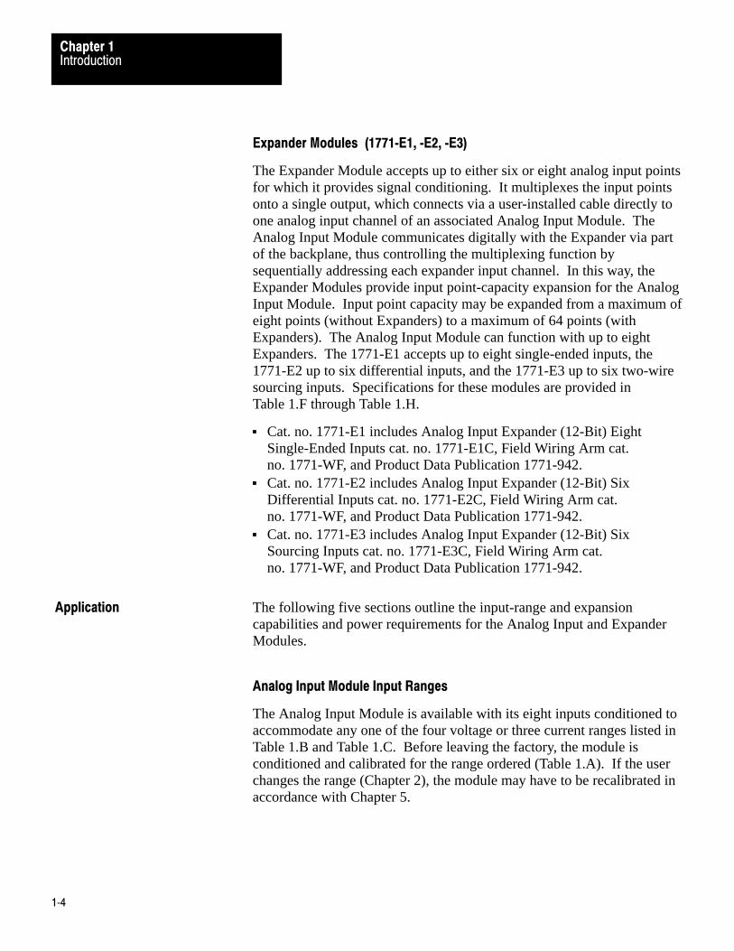
Table 1.BInput Voltage Ranges, 1771�IF
3�Digit BCD Operating Mode
Nominal VoltageRange Actual Range
CorrespondingBCD Output Range ∆ V/Bit
+1 to +5V DC 0 to +10V DC�10 to +10V DC 0 to +5V DC
+1 to +4.996V DC 0 to +9.990V DC
�10 to +9.980V DC 0 to +4.995V DC
000�999000�999000�999000�999
4 mV/Bit10 mV/Bit20 mV/Bit 5 mV/Bit
12�Bit Binary Operating Mode
Nominal VoltageRange Actual Range
CorrespondingBCD Output Range ∆ V/Bit
+1 to +5V DC 0 to +10V DC�10 to +10V DC 0 to +5V DC
+1 to +4.99902V DC 0 to +9.99756V DC
�10 to +9.99512V DC 0 to +4.99878V DC
0000�777780000�777780000�777780000�77778
0.98 mV/Bit2.44 mV/Bit4.88 mV/Bit1.22 mV/Bit
NOTE: The input voltage range is selectable for all eight channels as a unit, thus allchannels function with the same input voltage range.
Table 1.CInput Current Ranges, 1771�IF
3�Digit BCD Operating Mode
Nominal VoltageRange Actual Range
CorrespondingBCD Output Range ∆ I/Bit
+4 to +20 mA 0 to +20 mA�20 to +20 mA
+4 to +19.984 mA 0 to +19.980 mA
�20 to +19.960 mA
000�999000�999000�999
0.016 mA/Bit00.02 mA/Bit00.04 mA/Bit
12�Bit Binary Operating Mode
Nominal VoltageRange Actual Range
CorrespondingBCD Output Range ∆ I/Bit
+4 to +20 mA 0 to +20 mA�20 to +20 mA
+4 to +19.9961mA 0 to +19.9951mA
�20 to +19.9902mA
0000�777780000�777780000�77778
0.0039 mA/Bit0.0048 mA/Bit0.0098 mA/Bit
NOTE: The input current range is selectable for all eight channels as a unit, thus allchannels function with the same input current range.
IntroductionChapter 1
1�9
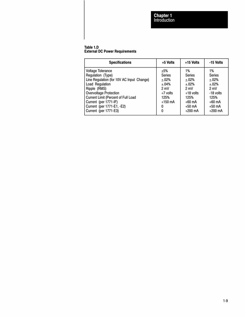
Table 1.DExternal DC Power Requirements
Specifications +5 Volts +15 Volts �15 Volts
Voltage ToleranceRegulation (Type)Line Regulation (for 10V AC Input Change)Load RegulationRipple (RMS)Overvoltage ProtectionCurrent Limit (Percent of Full LoadCurrent (per 1771�IF)Current (per 1771�E1, �E2)Current (per 1771�E3)
+5%Series+.02%+.04%2 mV+7 volts125%+150 mA00
1%Series+.02%+.02%2 mV+18 volts125%+60 mA+50 mA+200 mA
1%Series+.02%+.02%2 mV�18 volts125%+60 mA+50 mA+200 mA

IntroductionChapter 1
1�10
Table 1.ESpecifications, 1771�1F
Inputs per Module• Eight Single Ended
Module Location• Bulletin 1771 I/O Rack��2 Adjacent, Module Group Slots
Input Voltage Ranges (Nominal)• +1 to +5V DC• 0 to +10V DC• �10 to +10V DC• 0 to +5V DC
Input Current Ranges (Nominal)• +4 to +20 mA• 0 to +20 mA• �20 to +20 mA
Digital Resolution• Selectable, 3�Digit BCD or 12�Bit Binary
Input Overvoltage Protection• +35V DC• 25V RMS (Sinusoidal)
Input Impedance• >109 Ohms for Voltage Ranges• 250 Ohms for Current Ranges
BCD Output to Processor• 000 to 999 for Any Input Range
Binary Output to Processor• 0000 to 409510 for Any Input Range
Power Supply Current Requirement• 1.3 Amps
Ambient Temperature Rating• Operational: 0oC to +60oC (+32oF to +140oF)• Storage: �40oC to +85oC (�40oF to +185oF)
Relative Humidity Rating• 5 to 95% (without Condensation)
Electrical Isolation• 1,500V RMS (Transient)• Isolation is achieved by optoelectronic coupling between
the input circuit and the control logic.
Cable Type• Belden 8761 or Equivalent
Specifications for the A/D Converter• The A/D (Analog�to�Digital) Converter has the following
specifications:
Resolution• Selectable 3�Digit BCD (000�999) or 12�Bit Binary
(0000�409510)
Linearity (at 25oC)• +0.05% of Full Scale Relative Accuracy
Offset (at 25oC)• +0.05% of Full Scale
Gain (at 25oC)• +0.05% of Full Scale
Absolute Accuracy, Which Includes Linearity, Offset, and Gain at 25oC• +0.1% of Full Scale +1/2 LSB
Stability (Drift) Over the Full Temperature Range
Temperature Coefficient• +45 ppm/oC
Inaccuracy Due to Internal Electrical Noise• 3 Sigma Noise• <0.05% RMS (of Full Scale)
Input Filter Frequency Response• DC to 12 KHz (�3 dB Point)
Internal Scanning Rate/Eight Channels
• 5 msec without Expanders
Maximum Channel Sampling Rate• 1.3 ms per Channel��Worst Case with Expanders
A/D Settling Time (per Channel)• 200 microseconds
Actual A/D Sample Conversion Time• 25 Microseconds
Recalibration Time• Calibration should be checked at six�month intervals
to maintain specified accuracy.

IntroductionChapter 1
1�11
Table 1.FSpecifications, 1771�E1
Inputs per Module• Eight Single Ended
Module Location• 1771 I/O Rack
Input Ranges• +1 to +5V DC• 0 to +10V DC• +10V DC• +5V DC• 0 to +5V DC• +4 to +20 mA• +20 mA• 0 to +20 mA
Accuracy• +0.05 Percent of Range (Voltage Mode)• +0.07 Percent of Range (Current Mode)
Temperature Coefficient• +35 ppm/oC (Voltage Mode)• +45 ppm/oC (Current Mode)
Input Overvoltage Protection• +25V RMS (Voltage Mode)• +30 mA (Current Mode)
Input Impedance• 109 Ohms (Voltage Mode)• 250 Ohms (Current Mode)
Backplane Power Supply CurrentRequirement• +5V DC +150 mA
External Power Supply CurrentRequirements• +15V DC 50 mA• �15V DC 50 mA
Ambient Temperature Ratings• Operational: 0oC to 60oC
(32oF to 140oF)• Storage: �40oC to 85oC
(�40oF to 185oF)
Relative Humidity Rating• 5% to 95% (without Condensation)
Electrical Isolation• 1,500V RMS (Transient)• Isolation is achieved by optoelectronic
coupling between the input circuit andthe control logic.
Keying• 8�10 and 24�26
Output to 1771�IF Series B• +1 to +5V DC• 0 to +10V DC, • +10V DC• 0 to +5V DC
Table 1.GSpecifications, 1771�E2
Inputs per Module• Six Differential
Module Location• 1771 I/O Rack
Input Ranges• +1 to +5V DC• 0 to +10V DC• +10V DC• +5V DC,• 0 to +5V DC• +4 to +20 mA,• +20mA• 0 to +20 mA
Accuracy• +0.05 Percent of Range (Voltage Mode)• +0.07 Percent of Range (Current Mode)
Temperature Coefficient• +40 ppm/oC (Voltage Mode)• +50 ppm/oC (Current Mode)
Common Mode Voltage• +10V
Common Mode Rejection Ratio• 80 dB, DC to 120 Hz (Voltage Mode)• 20V pp, DC to 120 Hz (Current Mode)
Input Overvoltage Protection• +25V RMS (Voltage Mode)• +30 mA (Current Mode)
Input Impedance• 109 Ohms (Voltage Mode)• 250 Ohms (Current Mode)
Backplane Power Supply CurrentRequirement• 150 mA (+5V)
External Power Supply CurrentRequirements• +15V DC 50 mA• �15V DC 50 mA
Ambient Temperature Ratings• Operational: 0oC to 60oC
(32oF to 140oF)• Storage: �40oC to 85oC
(�40oF to 185oF)
Relative Humidity Rating• 5% to 95% (without Condensation)
Electrical Isolation• 1,500V RMS (Transient)• Isolation is achieved by optoelectronic
coupling between the input circuit andthe control logic.
Keying• 2�4 and 12�14
One Output Range to 1771�IF Series B• +1 to +5V DC• 0 to +10V DC• +10V DC• 0 to +5V DC

IntroductionChapter 1
1�12
Table 1.HSpecifications, 1771�E3
Inputs per Module• Six Two�Wire Sourcing (Supplies Signal Voltage)
Module Location• 1771 I/O Rack
Input Ranges• +4 to +20 mA and 0 to +20 mA
Accuracy• +0.07 Percent of Range
Temperature Coefficient• +45 ppm/oC
Input Overcurrent Protection• +30 mA (Each input is individually fused.)
Internal Loop Impedance• 285 ohms
Maximum External Loop Impedance• 1,000 ohms* for 20 mA
Backplane Power Supply Current Requirement• +5V DC +150 mA
External Power Supply Current Requirements**• +15V DC 200 mA• �15V DC 200 mA
Ambient Temperature Ratings• Operational: 0oC to 60oC (32oF to 140oF)• Storage: �40oC to 85oC (�40oF to 185oF)
Relative Humidity Rating• 5% to 95% Non�Condensing
Electrical Isolation• 1,500V RMS (Transient)• Isolation is achieved by optoelectronic coupling between
the input circuit and the control logic.
Keying• 2�4 and 22�24
Output to 1771�IF Series B• +1 to +5V DC• 0 to +10V DC• +10V DC• 0 to +5V DC
* The 1,000 ohms is the maximum external loop impedance at which the module can source +20 mA. This impedance isalso dependant upon the isolated transmitter's specifications. Refer to transmitter data sheets for further information.
** The module provides six 26V DC two�wire sourcing inputs foruse with two�wire transmitters. The 26V DC is derived from the 30V difference between the +15V and �15V external power supply (actually +11V and �15V).

Chapter
2
2�1
Installation
WARNING: To avoid injury to personnel and damage toequipment, disconnect and lock out AC power from thecontroller and system power supplies before installing andwiring modules.
After a configuration of Analog Input Modules or Analog Input andExpander Modules have been planned in accordance with the capabilitiesdefined in Chapter 1 and within the limitations described in “RackConfigurations,” physical installation can begin. It consists of selectingthe options as described in “Conditioning Options 1771-IF” and“Conditioning Options 1771-E1, -E2, and -E3;” inserting the modules intotheir I/O rack slots and making connections to the modules’ field wiringarms as per “Connections;” and then, when the rack configuration is firm,keying the module slots as specified in “Keying.” It is recommended thatChapter 2 be read through before beginning work and that all optionselections and connections be double checked against Chapter 2, beforeprogramming and start-up testing begin.
Module grouping limitations are as follows: Expander Modules must behoused in the same I/O rack with the associated Analog Input Module.Avoid placing either module close to AC or high voltage DC modules.The Analog Input Module requires two adjacent slots in the I/O rack, andthe two slots used must be of the same group. It cannot straddle twogroups. The Expanders require one slot each.
Analog Input Module cat. no. 1771-IF Series B can be conditioned tofunction as master or standalone. When the 1771-IF is expanded (usesassociated Expander Modules), it must be conditioned as a master. (A“master” is here defined as an intelligent I/O module that communicateswith associated Expander Modules via the backplane.) Whennon-expanded, the Analog Input Module is conditioned as a standalone.No more than two master 1771-IFs may reside in one I/O rack. Also, thenumber of master and standalone 1771-IFs that can be used in a given I/Orack is restricted by the presence of certain other intelligent I/O modulesin the same rack: Stepper Motor Assembly Modules cat. no. 1771-QA
General
Rack Configurations

InstallationChapter 2
2�2
(always master), Servo-Positioning Assembly Modules cat. no. 1771-QC (always master), Analog Output Module cat. no. 1771-OF (master or standalone), and Thermocouple Input Module cat.no. 1771-IX (always master). The restrictions exist on an I/O chassisbasis. The restrictions do not place limits on the number of modules in anI/O system.
Non-Expanded
The number of standalone 1771-IFs per I/O rack is limited only to thenumber of slot pairs available, provided there are no 1771-QAs,1771-QCs, master 1771-IFs, master 1771-OFs, or 1771-IXs.
Up to four standalone 1771-IFs can be used with one master 1771-OF,one master 1771-IF, or one 1771-IX (always master).
Up to three standalone 1771-IFs can be used with two master 1771-OFs, two master 1771-IFs, one master 1771-OF and one master1771-IF, or one 1771-QA or 1771-QC.
Up to two standalone 1771-IFs can be used with one 1771-IX (alwaysmaster) and one master 1771-IF or one master 1771-OF.
Expanded
There can be no more than two master 1771-IFs, one master 1771-IF,and one 1771-IX (always master), or one master 1771-IF and onemaster 1771-OF.
A master 1771-IF is not permitted with a 1771-QA or 1771-QC.
Consult the user’s manual of any other intelligent I/O modules involvedfor any grouping limitations.
DIP-switch conditioning required prior to inserting the module into theI/O rack is defined in the following paragraphs (Figure 2.1). Access tothe dual-inline package (DIP) switches is obtained by removing thecomponent side cover of the module (Figure 2.2).
CAUTION: Modules must not be removed from or insertedinto the I/O rack while system power is ON. Failure to observethis rule may result in damage to module circuitry.
Conditioning Options 1771�IF

InstallationChapter 2
2�3
Figure 2.1DIP Switch Locations, 1771�IF
R5
R6
R7
SW -1
SW -2
SW -3
Module FunctionSwitch
Range SelectionSwitch Assembly
On (current)Off (voltage)Voltage/CurrentSwitch Assembly 10457

InstallationChapter 2
2�4
Figure 2.2Component Side Cover
Remove Screws
Remove Screws
ComponentSide Cover
10458
Module Function Switch SW�1 (Figure 2.1, Figure 2.2, and Figure 2.3)
Position 1: If the module is configured as a standalone module, then thisswitch must be set to OFF. (Position 4 must also be set to OFF.) If themodule is to be a master to the Analog Input Expanders, this switch hasadditional meaning. If this is the only master module in the chassis, itmust be selected to Master 1 (OFF). If there is another master in thechassis, one must be selected to Master 1 and the other to Master 2. Toselect Master 2, set this position to ON.
NOTE: Check the selection of Position 4 (master/standalone).
Position 2: This switch set to ON selects three-digit BCD format forvalue words. Set to OFF it selects 12-bit binary format.
Position 3: This switch set to ON conditions module to accommodateblock transfer interface; set to OFF, it conditions module to accommodatesingle transfer interface.

InstallationChapter 2
2�5
Position 4: If there are no expanded Analog Input Modules, this switchmust be set to OFF. If the module is being used with Expander Modules,this switch must be set to ON, conditioning it as a master module.
Position 5: Set to OFF for normal operation, set to ON for calibration.
Voltage/Current Switch SW�2 (Figure 2.1)
All positions of this switch assembly are set to ON if the module is to beconditioned for current range inputs. All positions are set to OFF forvoltage range inputs.
Range Selection Switch SW�3 (Figure 2.1)
The ten positions of this switch assembly are set in accordance withTable 2.A for the input current or voltage range required for the eightinputs. If a change is made in these switch settings, recalibration (Chapter 5) is required.
Programming-plug conditioning required prior to inserting the modulesinto I/O rack slots is defined in the following paragraphs. Access to theprogramming-plug positions is obtained by removing the component sidecover of the module (Figure 2.2). Unused programming plugs are storedin the storage area of the circuit board.
The associated Analog Input Module is conditioned to be Master 1 or 2.Each Expander Module is conditioned to accommodate a Master 1 orMaster 2 Analog Input Module. Each Expander output voltage range isconditioned to accommodate the associated Analog Input Module voltageinput. Each Expander Module is also numbered 1 through 8 andprogramming-plug conditioned to correspond to that number. In addition,each Expander Module is conditioned to establish how many of its inputsare used and what voltage or current ranges its inputs will accept.
CAUTION: Modules must not be removed from or insertedinto the I/O rack while system power is ON. Failure to observethis rule may result in damage to module circuitry.
Conditioning Options 1771�E1,�E2, and �E3

InstallationChapter 2
2�6
Table 2.AVoltage/Current Ranges, Switch SW�3
Position
Range 1 2 3 4 5 6 7 8 9 10
+1 to +5V DC OFF OFF ON ON OFF ON OFF ON OFF OFF
+4 to +20 mA OFF OFF ON ON OFF ON OFF ON OFF OFF
+20 mA ON ON OFF OFF ON OFF ON ON OFF OFF
0 to +10V DC ON ON OFF OFF ON ON OFF ON OFF OFF
0 to +5V DC ON ON OFF OFF ON ON OFF ON OFF ON
0 to +20 mA ON ON OFF OFF ON ON OFF ON OFF ON
+10V DC ON ON OFF OFF ON OFF ON OFF ON OFF
Figure 2.3DIP Switch Assembly SW�1
1 2 3 4 5ON
OFF
ON
OFF
ON - MasterOFF - Standalone
ON - Master 2OFF - Master 1or Standalone
ON - Calibration of1 to 5V RangeOFF - Normal Operation
ON - BCD ModeOFF - Binary Mode
ON - Block TransferOFF - Single Transfer
ON
10459

InstallationChapter 2
2�7
Figure 2.4Programming�Plug Positions
1 7 9 3 0
181716151413121110987654321
Analog Input Module Master Selection
Refer to Figure 2.3 and set SW-1 Position 1 DIP switch to OFF(conditioning the Analog Input Module to be Master Number 1) if there isonly to be one master Analog Input Module in the I/O rack. Set SW-1Position 4 to ON, conditioning the module to be a master module.

InstallationChapter 2
2�8
If there are to be two master Analog Input Modules, set the SW-1 Position1 on one to OFF (designating that module as Master Number 1) and setSW-1 Position 1 on the other to ON (designating that module as MasterNumber 2). Set SW-1 Position 4 to ON on both modules, conditioningthem to be master modules.
Expander Master Selection
Refer to Figure 2.4 and insert a programming-plug into MASTER 1 if theExpander Module is to be used with an Analog Input Module conditionedto be Master Number 1 (see “Analog Input Module Master Selection”above). If the Expander Module is to be used with an Analog InputModule conditioned to be Master Number 2 (see “Analog Input ModuleMaster Selection” above), insert the programming-plug into MASTER 2.
Module Selection
Number the Expander Modules associated with each master Analog InputModule. Number them consecutively from 1 through 8 or throughwhatever the highest number will be. (A space is provided on the frontpanel of each Expander Module on which to write the number.) There canbe no more than eight Expander Modules associated with one expandedAnalog Input Module.
Refer to Figure 2.4 and insert programming plugs into MODULE M2,M1, and M0 positions for each Expander Module. Each of three plugs isinserted, one each, under M2, M1, and M0 in either the 0 position or 1position in accordance with the number of the Expander Module andTable 2.B.

InstallationChapter 2
2�9
Table 2.BModule Select
Expander Programming�Plug Position
Number M2 M1 M0
1 0 0 0
2 0 0 1
3 0 1 0
4 0 1 1
5 1 0 0
6 1 0 1
7 1 1 0
8 1 1 1
Channel Selection
Each 1771-E1 has eight inputs and each 1771-E2 or 1771-E3 has sixinputs. All inputs of a module need not necessarily be used.
Refer to Figure 2.4 and insert programming plugs into CHANNEL C2,C1, and C0 positions for each Expander Module. Each of three plugs isinserted, one each, under C2, C1, or C0 in either the 0 position or 1position in accordance with the number of inputs to be used on thatExpander Module and Table 2.C.
Table 2.CChannel Select
Number of Programming�Plug Position
Channels C2 C1 C0
1 0 0 0
2 0 0 1
3 0 1 0
4 0 1 1
5 1 0 0
6 1 0 1
7[1] 1 1 0
8[1] 1 1 1
[1] Defaults to six for 1771�E2 or 1771�E3.
InstallationChapter 2
2�10
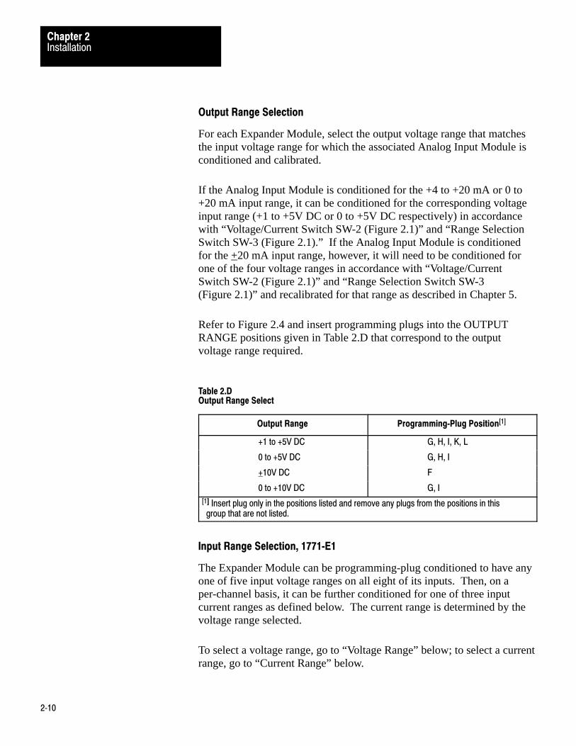
Output Range Selection
For each Expander Module, select the output voltage range that matchesthe input voltage range for which the associated Analog Input Module isconditioned and calibrated.
If the Analog Input Module is conditioned for the +4 to +20 mA or 0 to+20 mA input range, it can be conditioned for the corresponding voltageinput range (+1 to +5V DC or 0 to +5V DC respectively) in accordancewith “Voltage/Current Switch SW-2 (Figure 2.1)” and “Range SelectionSwitch SW-3 (Figure 2.1).” If the Analog Input Module is conditionedfor the +20 mA input range, however, it will need to be conditioned forone of the four voltage ranges in accordance with “Voltage/CurrentSwitch SW-2 (Figure 2.1)” and “Range Selection Switch SW-3(Figure 2.1)” and recalibrated for that range as described in Chapter 5.
Refer to Figure 2.4 and insert programming plugs into the OUTPUTRANGE positions given in Table 2.D that correspond to the outputvoltage range required.
Table 2.DOutput Range Select
Output Range Programming�Plug Position[1]
+1 to +5V DC G, H, I, K, L
0 to +5V DC G, H, I
+10V DC F
0 to +10V DC G, I
[1] Insert plug only in the positions listed and remove any plugs from the positions in this group that are not listed.
Input Range Selection, 1771�E1
The Expander Module can be programming-plug conditioned to have anyone of five input voltage ranges on all eight of its inputs. Then, on aper-channel basis, it can be further conditioned for one of three inputcurrent ranges as defined below. The current range is determined by thevoltage range selected.
To select a voltage range, go to “Voltage Range” below; to select a currentrange, go to “Current Range” below.

InstallationChapter 2
2�11
Voltage Range
Refer to Figure 2.4 and insert programming plugs into the INPUTRANGE positions given in Table 2.E that correspond to the input voltagerange required.
Current Range
The three current ranges available correspond to voltage ranges asfollows:
+1 to +5V DC +4 to +20 mA 0 to +5V DC 0 to +20 mA +5V DC +20 mA
To select a current range, first go to “Voltage Range” above and select thecorresponding voltage range. Then, refer to Figure 2.4 and insert aprogramming plug in each CURRENT RANGE position of S1 through S8that corresponds to an input, of 1 through 8, that is required to be a currentinput. If a plug is inserted in each of Positions S1 through S8, all inputswill be conditioned as current inputs. Any position of S1 through S8without a plug will be a voltage input.
Input Range Selection, 1771�E2
The Expander Module may be programming-plug conditioned to have anyone of five input voltage ranges on all six of its inputs. Then, on aper-channel basis, it can be further conditioned for one of three inputcurrent ranges as defined below. The current range is determined by thevoltage range selected.
To select a voltage range, go to “Voltage Range” below; to select a currentrange, go to “Current Range” below.
Voltage Range
Refer to Figure 2.4 and insert programming plugs into the INPUTRANGE positions given in Table 2.E that correspond to the input voltagerange required.

InstallationChapter 2
2�12
Current Range
The three current ranges available correspond to voltage ranges asfollows:
+1 to +5V DC +4 to +20 mA 0 to +5V DC 0 to +20 mA +5V DC +20 mA
Table 2.Einput Range Select, 1771�E1, �E2
Input Range Programming�Plug Position[1]
+1 to +5V DC[2] A, C, D, E
0 to +5V DC2 A, C
+10V DC No Plugs
0 to +10V DC C
+5V DC2 B
[1] Insert plug only in the positions listed and remove any plugs from the positions in this group that are not listed.
[2] For corresponding current ranges, refer to "Input Range Selection, 1771�E1".

InstallationChapter 2
2�13
Figure 2.5Analog Input Module Connections
1
2
3
4
5
6
7
8
9
10
11
12
Analog Common
Channel 1
Channel 3Analog Common
Channel 4Analog Common
+-
+15V DC
-15V DC
15V DCCommon
+5V DC
+5V DC Common
ExternalPowerSupply
When all eight channels are not used, the channels used must be consecutive beginning with channel 1.
All common terminals on field wiring arms are at the same eletrical point within the Analog Input Module.
Some analog source device output signals are not commpatible with the Analog Input Module and, therefore, require signal
1.
2.
Analog Input Module Field Wiring ArmFront View 1771-IF
1
2
3
4
5
6
7
8
9
10
11
12
Channel 5
Analog Comm
+5V DC
+5V DC Common
Channel 2
Analog Common
Not Used
3.
4.
10460
+
-
AnalogSource
Belden 8761 Cable
Floating Channel 6
Analog Comm
Channel 7
Analog Comm
Channel 8
Analog Comm
Power Available
Power Available Comm
[1]
ChassisGround
If external power supply has a power available output, connect it to the power available input of the Analog Input Module.If the supply does not have a power available output, use a jumper to short the power available terminals of the fieldwiring arm as shown.
conditioning devices between them and the Analog Input Module.

InstallationChapter 2
2�14
Figure 2.6Analog Input Module with Expanders, Multiplex Connections
1
2
3
4
5
6
7
8
9
10
11
12
Channel 2
Analog Common-
+AnalogSource
Floating
Analog Common
Channel 1
Analog Output
Common
+15V DC
-15V DC
+-
+15V DC
-15V DC
15V DC Common
Channel 3Analog Common
Channel 4Common
+-
+15V DC
-15V DC
15V DC Common
ChassisGround
+5V DC
+5V DC Common
Floating
Belden8761Cable
ExternalPowerSupply
Figure2-7
Expender Module Field Wiring ArmSide View 1771-E1, E2, and E3
2+- 15V DC Comm
Not Used
10461
Analog Input Module Field Wiring ArmFront View 1771-IF
1
2
3
4
5
6
7
8
9
10
11
12
Channel 5
Analog Comm
Power AvailablePower AvailableComm
+5V DC
+5V DCCommon
[1]Not Used
15V DC common on expander Module is not used if external +-
1.
2.
Channel 6
Analog Comm
Channel 7
Analog Comm
Channel 8
Analog CommAnalog
If external power supply has a power available output, connect it to the power available input of the Analog Input Module.If the supply does not have a power available output, use a jumper to short the power available terminals of the fieldwiring arm as shown.
same on that is concted to the Anlog Input Module as shown.+- 15V power supply conneted toExpander Module is the
To select a current range, first go to “Voltage Range” above and select thecorresponding voltage range. Then, refer to Figure 2.4 and insert aprogramming plug in each CURRENT RANGE position of D1 throughD6 that corresponds to an input, of 1 through 6, that is required to be acurrent input. If a plug is inserted in each of Positions D1 through D6, allinputs will be conditioned as current inputs. Any position of D1 throughD6 without a plug will be a voltage input.

InstallationChapter 2
2�15
Input Range Selection, 1771�E3
The Expander Module may be programming-plug conditioned to haveeither of two current ranges on all six inputs. Refer to Figure 2.4 andinsert programming plugs into the INPUT RANGE positions given inTable 2.F that correspond to the input current range required.
When the Analog Input Module or the Analog Input Module andassociated Expander Modules have been conditioned in accordance with“Conditioning Options 1771-IF” and “Conditioning Options 1771-E1,-E2, and -E3,” the Analog Input Module and associated ExpanderModules, if any, can be inserted into an I/O rack, interconnected asrequired, and connected to external devices in accordance with thefollowing paragraphs. Appendix A outlines installation practices.
CAUTION: Modules must not be removed from or insertedinto the I/O rack while system power is ON. Failure to observethis rule may result in damage to module circuitry.
Input Cables 1771�IF
Figure 2.5 shows input cable connections for connecting analog inputpoints directly to the Analog Input Module. Note that these inputs are thesame ones used to connect the multiplex cables (see below) whenExpander Modules are used.
Multiplex Cables
Refer to Figure 2.6. Connect one shielded twisted pair cable between thefield wiring arm of each Expander Module to the field wiring arm of theassociated Analog Input Module.
The number written on the front panel of the Expander Module (thenumber for which it was programming-plug conditioned in accordancewith “Conditioning Options 1771-E1, -E2, and -E3”) corresponds with thechannel number of the Analog Input Module’s field wiring arm. Forexample, Expander Module Number 1 analog output (Terminals 5 and 6)connects to Analog Input Module Channel 1 (Left Swing Arm Terminals 1 and 2). Expander Module Number 2 connects to AnalogInput Module Channel 2, etc. Provide service loops so that field wiringarms can pivot freely.
Connections

InstallationChapter 2
2�16
Input Cables 1771�E1, �E2, and �E3
For each Expander Module, refer to Figure 2.7 for input cableconnections. Note that if all the inputs of an Expander Module are notused, those that are used must be consecutive beginning with Channel 1.
Input Power
The Analog Input and Expander Modules each require power from thebackplane and from an external supply.
Analog Input Module
The Analog Input Module receives +5V DC power from the backplane ofthe I/O rack in which it is housed. The module draws 1.3 amperes fromthis supply. This value should be used to find the total current drawn byall modules in an I/O rack to determine that the power supply will not beoverloaded. (Do not use Power Supply cat. no. 1772-P1 prior to Series B, 1771-P2 prior to Series B, 1774-P1 prior to Series C, or 1778-P2prior to Series C and only with PLC).
Table 2.FInput Range Select, 1771�E3
Input Range Programming�Plug Position[1]
+4 to +20 mA A, C, D, E
0 to +20 mA A, C
[1] Insert plug only in the positions listed and remove any plugs from the positions in this group that are not listed.

InstallationChapter 2
2�17
Figure 2.7Analog Input Expanders, Input Connections
+
-
(18) Channel 1
(17) Channel 2
(16) Common
Common
+
++
++
++
+
-
-
-
-
-
+
-
+
AnalogSource
AnalogSource
(15) Channel 3(14) Channel 4(13) Common(12) Channel 5(11) Channel 6(10) Common
(9) Channel 7(8) Channel 8(7) Common(6) Analog Out(5) Common(4) + 15V DC(3) - 15V DC(2) 15V DC Common
(1) Not Used
Figure 2�6
Floating
Belden 8761 Cables1771-E1ChassisGround
(18) Channel 1 (+ Lead)AnalogSource
(6) Analog Out(5) Common(4) + 15V DC(3) - 15V DC(2) 15V DC Common
(1) Not Used
Figure
Floating
Belden 8761 Cable
1771-E2ChassisGround
(17) Channel 1 (- Lead)
(16) Channel 2 (+ Lead)
(15) Channel 2 (- Lead)(14) Channel 3 (+ Lead)
(13) Channel 3 (- Lead)(12) Channel 4 (+ Lead)
(11) Channel 4 (- Lead)(10) Channel 5 (+ Lead)
(9) Channel 5 (- Lead)(8) Channel 6 (+ Lead)
(7) Channel 6 (- Lead)
(18) Channel 1 (+ Lead)AnalogSource
(6) Analog Out(5) Common(4) + 15V DC(3) - 15V DC(2) 15V DC Common
(1) Not Used
Figure
Floating
Belden 8761 Cable
1771-E3ChassisGround
(17) Channel 1 (- Lead)
(16) Channel 2 (+ Lead)
(15) Channel 2 (- Lead)(14) Channel 3 (+ Lead)
(13) Channel 3 (- Lead)(12) Channel 4 (+ Lead)
(11) Channel 4 (- Lead)(10) Channel 5 (+ Lead)
(9) Channel 5 (- Lead)(8) Channel 6 (+ Lead)
(7) Channel 6 (- Lead)
NOTES:
1. When all eight inputs are not used, the channelsused must be consecutive beginning with channel 1.
2. Incoming analog signals cannot be tied to ground.
3. All common terminals are at the same electricalpoint within the module.
4. Some analog source device output signals are notcompatible with this module and, therefore, requiresignal conditioning devices between their outputs andthis module.
NOTES: 1. When all six channels are not used, the channels usedmust be consecutive beginning with channel 1.
2. Analog signals must be within the +10V common modevoltage range which is referenced to the analog systemcommon.
3. Some analog source device output signals are notcompatible with this module and, therefore, require signalconditioning devices between their outputs and this module.
NOTES: 1. When all six channels are not used, thechannels used must be consecutive beginningwith channel 1.
2. Incoming analog signal sources must beisolated from ground.
3. Some analog source device output signalsare not compatible with this module and,therefore, require signal conditioning devicesbetween their outputs and this module.
2�6
2�6

InstallationChapter 2
2�18
Refer to Figure 2.5 for external +5V and +15V power supply connectionsto the Analog Input Module. This module draws 150 mA (+5V), 60 mA(+15V DC), and 60 mA (-15V DC) from the external power supply.These values should be used to find the load handling capability requiredof the external power supply.
Expander Module
The Expander Module receives +5V DC power from the backplane of theI/O rack in which it is housed. Each Expander draws 150 mA from thebackplane power supply. This value should be used to find the totalcurrent drawn by all modules in an I/O rack to determine that the powersupply will not be overloaded.
Refer to Figure 2.6 for external +15V DC power supply connections tothe Expander Modules. Note that if the same external power supply thatservices the Analog Input Module is used for the Expanders, the +15V DC common (Expander Terminal 2) should not be connected to theexternal power supply common. If a separate external power supply isused for the Expanders, the power supply common should be connected toTerminal 2 of the Expanders’ Field Wiring Arms. The 1771-E1 and1771-E2 Expanders each draw 50 mA (+15V DC) and 50 mA (-15V DC)from the external power supply and the 1771-E3 draws 200 mA (+15V DC) and 200 mA (-15V DC). These values should be used to findthe load handling capability required of the external power supply.
Refer to Figure 2.8. The Analog Input Module has a front panelDIAGNOSTIC LED that is defined in detail in Chapter 3 under“Diagnostics.” The Expander Modules have a green LED (DC ON) onthe front panel that lights when +5V DC backplane power and external+15V DC power power are present. The 1771-E3 has an additional redLED indicator (FUSE BLOWN) that lights when any one of the sixanalog input fuses opens. Fuses are replaced with 1/32A fuses (Littlefuse 312.031).
CAUTION : Replace fuses only with recommended value andtype. Use of other types of fuses could result in improperoperation due to internal resistance of the fuse.
Indicators and Fuses

InstallationChapter 2
2�19
Figure 2.8Indicators
Diagnostic
DC On
1771 - IF 1771 - E1 1771 - E2 1771 - E3
17927
FuseBlown
DC OnDC On
Key the backplane connector for each Analog Input and ExpanderModule. Plastic keying bands are shipped with the I/O chassis. Thesekeying bands help to prevent insertion of the wrong module into aparticular I/O rack slot.
Refer to Figure 2.9 through Figure 2.12. Snap keying bands onto theupper backplane connector between these numbers:
1771-IF: 6-8 and 22-24 (Left Connector) 4-6 and 32-34 (Right Connector)
1771-E1: 8-10 and 24-26 1771-E2: 2-4 and 12-14 1771-E3: 2-4 and 22-24
Keying bands may be placed on the backplane connectors by means ofneedlenose pliers. These bands can be easily repositioned as subsequentsystem needs require.
Keying

InstallationChapter 2
2�20
Figure 2.9Keying, 1771�IF
24681012141618202224262830323436
24681012141618202224262830323436 10463
LeftUpperBackplaneConnector
RightUpperBackplaneConnector
KeyingBands
Figure 2.10Keying, 1771�E1
24681 01 21 41 61 82 02 22 42 62 83 03 23 43 6 10464
KeyingBands

InstallationChapter 2
2�21
Figure 2.11Keying, 1771�E2
24681 01 21 41 61 82 02 22 42 62 83 03 23 43 6 10465
KeyingBands
Figure 2.12Keying, 1771�E3
24681 01 21 41 61 82 02 22 42 62 83 03 23 43 6 10466
KeyingBands

Chapter
3
3�1
Programming
This chapter provides information required to program a programmablecontroller (PC) processor to interface with an Analog Input Module withor without associated Expander Modules. Appendices B through F supplysample application programs. Depending on the PC processor being used,two methods of interface are available--single transfer and block transfer.Table 3.A identifies which processors may be used with block transfer andwhich may be used with single transfer local configuration and singletransfer remote configuration.
CAUTION: Single transfer interface must not be used inremote applications except with the PLC ProgrammableController.
The information provided in this chapter supplements the informationprovided in related manuals. Each programmable controller user’smanual or programming manual includes a detailed user’s instruction setfor its processor and operating procedures for using an IndustrialTerminal, or other programming panel, to write a user program into thememory of the processor.
General

ProgrammingChapter 3
3�2
Table 3.AProcessor Interface Capabilities
Block Single Transfer
Processor Transfer Local[1 ] Remote[2]
Mini�PLC�2/15 (Cat. No. 1772�LV) YES YES N/A
Mini�PLC�2 (Cat. No. 1772�LN3) YES YES N/A
Mini�PLC�2 (Cat. No. 1772�LN1, �LN2) NO YES N/A
PLC�2/20 (Cat. No. 1772�LP1, �LP2) YES YES NO3
PLC�2/30 (Cat. No. 1772�LP3) YES YES NO3
PLC�3 (Cat. No. 1775�L1, �L2) YES N/A NO3
PLC (Cat. No. 1774�LB2, �LC2) NO N/A YES
PLC�2 (Cat. No. 1772�LR) NO YES NO[3]
[1] I/O modules interfaced with the processor via I/O Adapter Module Cat. No. 1771�AL.
[2] I/O modules interfaced with the processor via a remote I/O Scanner/Distribution Panel and Remote I/O Adapter Module Cat. No. 1771�AS.
[3] Single transfer may be used with these processors in the remote configuration whenthe Analog Input Modue is in the calibrate mode.
Refer to Figure 3.1. The Analog Input Module scans its eight analoginput channels, converts their incoming analog values to digital values,and stores the digital values in on-board microcomputer memorylocations. When an Expander Module is connected to one of the AnalogInput Module’s input channels, the incoming analog values of each of theExpander’s input channels are also converted, by the Analog InputModule, to digital values and stored. The stored value words areperiodically transferred to PC processor memory via either the singletransfer or block transfer method of interface. For single transfer, onevalue word is transferred at a time. For block transfer, up to 64 valuewords can be transferred at a time. Block transfer will not occur until theAnalog Input Module has completed scanning all of its input channels.
Operational Overview

ProgrammingChapter 3
3�3
Figure 3.123�Channel Configuration
AnalogInputModule1771–IFSeries B
1
2
3
4
5
6
7
8
ExpanderModule1771–E1
No. 1
ExpanderModule1771–E2
No. 2
ExpanderModule1771–E2
No. 3
ExpanderModule1771–E3
4
5
6
7
8
1
2
3
4
5
6
1
2
3
4
5
6
1
2
3
BackplaneBus toPC Processor
5 Inputs
8 Inputs
6 Inputs
4 Inputs
10467
Note:This diagram shows an analog inputsystem that has been expanded froma maximum of 8 input points (withoutExpanders) to a maximum of 25 points(with 3 Expanders). Only 23 inputs areused.
Not Used

ProgrammingChapter 3
3�4
The following three sections describe two general block transfer formatsand define the data table file into which the value words are transferred.
Block Transfer (BLOCK X�FER)
Figure 3.2 shows a general method of programming a PC processor forblock transfer. This is the general format used with Mini-PLC-2/15 andPLC-2/30 Processors when programming with a 1770-T3 IndustrialTerminal.
Figure 3.2General Block Transfer Program (Block XFer)
ENBLOCK TRANSFER READ
DATA ADDR
MODULE ADDR
BLOCK LENGTH
FILE
040
130
08
070
DN
013
07113
07
10468
When the user depresses the BLOCK X-FER key on the IndustrialTerminal, the rung block shown in Figure 3.2 is displayed. The user thendepresses either the 1 key or 0 key on the keypad to select either blocktransfer read or block transfer write, respectively. Block transfer read isrequired to service the Analog Input Module. The user then enters thefour values inside the rung block through the keypad. Example values040, 130, 08, and 070 are shown in Figure 3.2.
NOTE: Bit Number 7 (Bit 01307 in this example) is also referred to asthe enable (EN) bit. It is set to ON when the rung block is enabled. Bit 11307 in this example is referred to as the done (DN) bit. It is set toON when the block transfer is complete.
Data Address 040 is the address of the first available timer-counter wordlocation in the PC processor’s data table.
Module Address 130 is part of the address of the output image table bytelocation corresponding to the Analog Input Module: Rack 1, Group 3,
Block Transfer Interface

ProgrammingChapter 3
3�5
Slot 0 in this example. This automatically determines the Analog InputModule’s output image table and input image table byte addresses (0130and 1130 respectively), on the OUTPUT ENERGIZE instructionsattached to the rung block.
Block Length 08 is the number of value words to be transferred from theAnalog Input Module. [If the block length entry is zero, the default value,the module will send the maximum number of channels (all) beingscanned.]
File Address 070 is the address of the first data table word location of theblock file of locations into which the value words are to be transferred.
Module Address 130 is stored in Timer-Counter Word Location 040. FileAddress 070 is automatically stored in the Timer-Counter Word Location(140) that is 100 above Timer-Counter Word Location 040.
When the PC processor executes the BLOCK TRANSFER instructionduring normal program cycle, the instruction directs the processor togenerate a control byte and write it into Output Image Table ByteLocation 0130. The control byte consists of the block length (08) and thedirection indicator (7), which is also the enable (EN) bit.
When the PC processor subsequently updates the I/O modules byscanning the output image table, it transfers the control byte to the AnalogInput Module and then continues updating the I/O modules. When readyfor block transfer, the Analog Input Module responds to the control wordby activating a hardware status line.
The PC processor polls the status line every I/O scan. The first time thestatus line is active when polled, the processor responds by searching thedata table for a location that contains Module Address 130. It will findthe module address in Timer-Counter Word Location 040, where itpreviously stored it. Having found the location containing the moduleaddress, it adds 100 to the address to calculate the address of the locationwhere it previously stored the file address (Timer-Counter Word Location 140).
The processor then reads File Address 070 out of Location 140. FileAddress 070 points to the first word location of the block file into whichthe value words are to be transferred. Block transfer then proceeds,transferring the eight value words out of the Analog Input Module into theblock file pointed to by the File Address 070. When block transfer is

ProgrammingChapter 3
3�6
complete, the processor sets the done (DN) bit and returns to normal I/Oscan beginning where it left off when it interrupted itself as a result ofpolling an active status line.
Block Transfer (GET�GET)
Figure 3.3 shows a general method of programming a PC processor forblock transfer. This is the general format used with the PLC-2/20 andMini-Processor Module Processors.
Figure 3.3General Block Transfer Program (GET�GET)
01200
RUNG A
01201
RUNG B
01202
RUNG C
01203
RUNG D
01204
RUNG E
01205
RUNG F
030
120
130
050
01207
G GRUNG G
10469
The Rung G OUTPUT ENERGIZE instruction initiates block transfer. Itsaddress (01207) specifies Bit Number 7 of output image table lower byteof Word 012. In this example, this output image table word locationcorresponds to the Analog Input Module in Rack 1, Group 2, Slot 0. BitNumber 7 being set to ON specifies block transfer read. (For blocktransfer write, Bit Number 6 would be set to ON instead.) Block transferread is required to service the Analog Input Module.

ProgrammingChapter 3
3�7
Bit Numbers 0 through 5 of the same output image table upper byte ofWord 012 are set to ON or not set to ON to define a six-bit binary numberthat specifies the number of words to be transferred. Rungs A through Fset all six bits to ON, thus specifying that 63 value words be transferred.If all of Bits 0 through 5 are left OFF (Rungs A through F left out of theprogram), default value, up to 64 words will be transferred. If only Rungs A and B are included, three words will be transferred, etc.
In the example in Figure 3.3, the Analog Input Module location (120) isstored in the first available timer-counter word location (030). The firstword location (050) of the block file of locations, into which the valuewords of the Analog Input Module are to be transferred, is stored inTimer-Counter Word Location 130 (100 above 030).
When Rung G is executed by the PC processor in the normal course of itsprogram cycle, the processor is directed by the instructions of the rung toperform the following operations:
The first GET instruction directs the PC processor to read Analog InputModule Location 120 out of Timer-Counter Word Location 030.
The second GET instruction directs the PC processor to read theaddress (050) of the first word location of the block file out ofTimer-Counter Word Location 130.
The OUTPUT ENERGIZE instruction directs the PC processor to setBit Number 7 of Output Image Table Word Location 120 to ON.
During the subsequent output image table scan part of its program scan,the PC processor transfers the ON condition of Bit Number 7 to theAnalog Input Module. The Analog Input Module responds by activating ahardware status line.
The PC processor polls the status line every I/O scan. When it finds thestatus line active, it performs block transfer from the Analog InputModule at I/O Rack Location 0120 to the block file beginning at WordLocation 050. Completion of block transfer is signified by the setting toON of Bit 7 in the Analog Input Module’s Input Image Table ByteLocation 1120.
Block Transfer File
Value words are block transferred into a block file of data table wordlocations in the PC processor’s memory. Each word location in the blockfile corresponds to a specific Expander Module input channel or AnalogInput Module input channel. The configuration of that correspondence is

ProgrammingChapter 3
3�8
determined by how many Expander Modules are used, how many inputchannels of each Expander Module are used, and how many of the AnalogInput Module’s non-expanded input channels are used. These factorsdictate the correspondence because they dictate how some of theExpander’s programming-plug positions are selected and how theExpanders are connected to the Analog Input Module. Specificinstructions for making these programming-plug-position selections andconnections are given in Chapter 2 under “Module Selection,” “ChannelSelection,” and “Multiplex Cables.” In summary, these instructionsspecify the following:
When less than eight Expanders are used, they are connected to theAnalog Input Module’s input channels in consecutive order, beginningwith Expander 1 connected to Analog Input Module Channel 1. Therecan be no gap in the order.
Each Expander is programming-plug conditioned to correspond withthe Analog Input Module channel it is connected to.
Each Expander is programming-plug conditioned to correspond withthe number (quantity) of its own input channels that are to be used.The field wiring arm connections must be consecutive beginning withthe Channel 1 input. There can be no gap in the order.
Table 3.B demonstrates the correspondence that would result fromconditioning and connecting the 23-channel configurations shown inFigure 3.1 in accordance with the instructions in Chapter 2 under “ModuleSelection,” “Channel Selection,” and “Multiplex Cables.”
This table demonstrates how consecutive locations in the block filecorrespond to input channels for the representative configuration inFigure 3.1.

ProgrammingChapter 3
3�9
Table 3.BBlock File Correspondence Example
Block FileLocation
Expander ModuleNumber
Expander ModuleChannel
Analog Input ModuleChannel
1 1 1
2 1 2
3 1 3
4 1 4
5 1 5
6 1 6
7 1 7
8 1 8
9 2 1
10 2 2
11 2 3
12 2 4
13 2 5
14 2 6
15 3 1
16 3 2
17 3 3
18 3 4
19 4
20 5
21 6
22 7
23 8

ProgrammingChapter 3
3�10
The following two sections describe the single transfer format and theassociated channel select word.
CAUTION: Single transfer must not be used in remoteapplications except with the PLC Programmable Controller.Otherwise, the integrity of the transferred value words will notbe maintained. Single transfer, however, may be used in allcases when the Analog Input Module is in the calibrate mode.Refer to Table 3.A for definitions of local and remoteconfigurations.
Single Transfer
Figure 3.4 shows a general method of programming a PC processor forsingle transfer. This is a general format used with any Allen-Bradley PCprocessor.
When Rung A is enabled, the OUTPUT ENERGIZE instruction directsthe PC processor to write Channel-Select Bit 0X into Output Image TableLower Byte Location 012. Lower Byte Location 012 corresponds to theAnalog Input Module upon which single transfer is to be performed.
When the PC processor next updates the I/O output modules, by scanningthe output image table, it transfers Channel-Select Bit 0X from OutputImage Table Byte Location 0120 to the Analog Input Module.
The Analog Input Module responds to the channel-select bit by assertingthe value word corresponding to the analog input channel selected. If theasserted word is declared valid by the Analog Input Module, the word’sbit numbers 17 and 16 will be set to ON and OFF respectively.
After that, the first time the PC processor scans the input image table toupdate it with asserted values from input I/O modules, the PC processortransfers the Analog Input Module’s asserted value words to the inputimage table word location (112) that corresponds to the Analog InputModule.
The next time the PC processor executes Rung B (Figure 3.4) theEXAMINE ON and EXAMINE OFF instructions direct the PC processorto read Bits 17 and 16 of the asserted value word in Input Image TableWord Location 112. If it finds that Bit Numbers 17 and 16 of that word
Single Transfer Interface

ProgrammingChapter 3
3�11
are ON and OFF respectively, Rung B is enabled. With Rung B enabled,the GET-PUT instruction pair directs the PC processor to transfer theasserted value word from Input Image Table Word Location 112 to UserMemory Word Location 050. The single transfer for one value word isthus complete.
When there are Expanders associated with the Analog Input Module, twochannel-select bits must be used--one to select the Expander and one toselect the analog input channel of the Expander. Figure 3.5 shows howtwo rungs are used. Rung A selects the Expander Module channel withBit 0X. Rung B selects the Expander with Bit 1Y.
Channel Select Word
The channel select word used in single transfer consists of one 16-bitword with either one or two bits set to the ON condition and theremaining bits left in the OFF condition. Figure 3.4 and Figure 3.5 showhow the one or two bits are set. Bit 0X selects either the Analog InputModule channel in the non-expanded configuration or the input channel ofthe Expander Module in the expanded configuration. Bit 1Y selects anExpander in the expanded configuration. An Analog Input Module’snon-expanded channel is also selected by Bit 0X in the expandedconfiguration. Figure 3.6 demonstrates how bit selection corresponds tochannel selection.
Figure 3.4General Single Transfer Program without Expanders
0120X
RUNG A
11216 112 050
/ GRUNG B
11217
PUT
10470

ProgrammingChapter 3
3�12
Figure 3.5General Single Transfer Program with Expanders
RUNG A
0121Y
RUNG B
11216 112 050
/ GRUNG C
10471
11217
PUT
0120X
Figure 3.6Channel Select Word
17 16 15 14 13 12 11 10 07 06 05 04 03 02 01 00
8 7 6 5 4 3 2 1
Analog Input ChannelNumber of 1 through 8
Not Used
Example: To select channel 5, set bit 04 to ON.
A. 1771-IF Series B without Expander Modules
Analog Input ChannelNumber of 1 through 8
Expander Number
B. 1771-IF Series B with 8 Expander Modules
Example: To select channel 6 of Expander 3, set bits 05 and 12 to ON.
of 1 through 8of Selected Expander
17 16 15 14 13 12 11 10 07 06 05 04 03 02 01 00
8 7 6 5 4 3 2 1
17 16 15 14 13 12 11 10 07 06 05 04 03 02 01 00
8 7 6 5 4 3 2 1
Analog Input ChannelNumber of 1 through 8
Expander Number
C. 1771-IF Series B with 4 Expander Modules
4 3 2 1
of 1 through 4of Selected Expander
Example 1: To select 1771�IF channel 7, set bit 06 to ON.
Example 2: To select channel 6, of Expander 2, set bits 05 and 12 to ON.
and 1771-IF AnalogInput Channel Numberof 5 through 11
10472
8 7 6 5 4 3 2 1

ProgrammingChapter 3
3�13
The digital value word or words that the Analog Input Module forwards tothe PC processor when the processor requests single transfer or blocktransfer can be in one of two formats as shown in Figure 3.7. Either theBCD (binary coded decimal) format or the straight binary format is DIP-switch selected on the Analog Input Module. In either case, the wordconsists of a 12-bit value and four status bits.
Refer to Figure 3.7. The underflow bit, set to ON, indicates that the valueforwarded is equal to or less than zero. The overflow bit, set to ON,indicates that the value forwarded is equal to or greater than full scale.The diagnostic bit is set to ON whenever a fault is detected. The datavalid bit is reset to OFF whenever external power loss is detected or thediagnostic bit is set. The diagnostic and data valid bits are detailed in thefollowing section.
Figure 3.7Value Word and Status Bits
17 16 15 14 13 12 11 10 07 06 05 04 03 02 01 00
X102 X101 X100
Underflow (< Bottom)
Overflow (> Full)
Diagnostic
Data Valid
BCD Format
17 16 15 14 13 12 11 10 07 06 05 04 03 02 01 00
Binary Format
Underflow (< Bottom)
Overflow (> Full)
Diagnostic
Data Valid
12–bit Binary
10473
(ON for Fault)
(ON for Data Valid)
Value Word
Status Bits

ProgrammingChapter 3
3�14
The following paragraphs define the self-diagnostics performed by theAnalog Input Module at power-up and during normal operation.
Initialization
At power-up, the Analog Input Module checks its RAM and ROMmemory; counts its unexpanded channels, Expander Modules, andchannels per Expander.
Faults
If the above checks reveal any of the following faults, the Analog InputModule will respond as described under “Response” below:
1. Memory error detected
2. Expander Module missing (not numbered sequentially beginningwith 1)
3. Expander Module incorrectly programming-plug conditioned
4. Expander Module output connected to wrong Analog Input Moduleinput
5. Another intelligent module is tying up the bus for an overly longperiod of time
6. Expander Module diagnostics fail
Response
For Analog Input Modules being interfaced via block transfer and withrespect to Steps 1 and 2 above, the Analog Input Module will illuminateits front-panel DIAGNOSTIC LED and halt (on-board microcomputerprogram run stops). No block transfer will occur. With respect to Steps 4, 5, and 6 above, scan continues. Diagnostic bits are set for badchannels. This can also be detected by the user by examination of Bit 7 inthe input image table word corresponding to the Analog Input Module.Bit 7 will be OFF if block transfer did not occur. It may not be possible,however, to visually detect the status of Bit 7 on the screen of anindustrial terminal, since, depending on application programming, blocktransfer may occur too frequently to activate the screen. In this case,
Diagnostics

ProgrammingChapter 3
3�15
additional program rungs may be used to allow Bit 7 of the input andoutput image table bytes to start and stop a watchdog timer that, upontiming out, latches a flag bit. Refer to Appendix C for applicationprogramming that uses a watchdog timer.
For Analog Input Modules being interfaced via single transfer, the AnalogInput Module will illuminate its front panel DIAGNOSTIC LED and setits diagnostic status bit. The user can detect the diagnostic bit byexamination of the input image table word corresponding to the AnalogInput Module. All other bits in the value word will be reset to OFF.
Normal Operation
The following checks and responses can occur after the Analog InputModule has passed the initialization check:
Limited Memory Check
After the Analog Input Module has completed each scan of its expandedand non-expanded analog input channels, it performs a limited check onits RAM and ROM memory. If this check reveals a fault, the AnalogInput Module responds as described under “Response” above.
Expander Scan Check
If the Analog Input Module fails to communicate with an ExpanderModule that was present during power-up, the Analog Input Moduleperforms the following: It sets the diagnostic status bit to ON and resetsall other bits in the value word to OFF for each value word correspondingto each input of the Expander or Expanders affected. The Analog InputModule also illuminates its front panel DIAGNOSTIC LED and continuesto service all non-expanded inputs.
Incorrect Channel Select Word (Single Transfer)
If a non-valid channel select word is transferred to the Analog InputModule, the Analog Input Module responds by resetting all bits of thecorresponding value word to OFF. If another fault has been detected aswell, the diagnostic status bit will be set to ON.

ProgrammingChapter 3
3�16
Incorrect Control Word (Block Transfer)
If a non-valid control word is transferred to the Analog Input Module, theAnalog Input Module responds by inhibiting the block transfer currentlyin progress.

Chapter
4
4�1
Troubleshooting
Table 4.A lists the probable causes and corrective actions for each of anumber of common trouble indications, due to hardware failure, incorrectprogramming, or incorrect installation, of Analog Input Moduleinstallations with Expander Modules.
NOTE: The red LED on the front panel of the Analog Input Module willbe on in the standalone mode if one or both of the following conditionsexist:
1. Analog Input Module component failure
2. communication fault (ladder diagram programming error)
Table 4.ATroubleshooting
Indication Probable Cause Corrective Action
Incorrect data in final storage word locations. Severed or disconnected input cableassociated with the affected channel orchannels.
Repair/replace appropriate cable or cables(Chapter 2 under "Connections").
Output range of Expander does not matchAnalog Input Module's input range.
Condition Expander output to match AnalogInput Module input (Chapter 2 under "OutputRange Selection").
Analog Input Module is conditioned for BCDinstead of binary or for binary instead of BCD.
Condition the Analog Input Module for thedesired value word format, of BCD or binary[Chapter 2 under "Module Function Switch"SW-1 (Figures 2-1, 2-2, and 2-3)].
Input range of Expander does not matchrange of actual input point.
Condition Expander to match actual range ofinput point (Chapter 2 under "Input RangeSelections, 1771-E1, -E2, and -E3"").
General

TroubleshootingChapter 4
4�2
Indication Corrective ActionProbable Cause
Analog Input Module's front panelDIAGNOSTIC LED is ON and the Expander'sfront panel green LED is ON.
Expanders are not conditioned in accordancewith their numbers.
Condition Expanders for their numbers(Chapter 2 under "Module Selection").
Analog Input Module or one or moreExpanders is not conditioned correctly forMaster 1 or Master 2.
Condition Analog Input Module andExpanders all for either Master 1 or Master 2(Chapter 2 under "Analog Input ModuleMaster Selection" and "Expander MasterSelection").
Expanders are not connected to the AnalogInput Module in accordance with theirnumbers.
Connect the Expanders to the Analog InputModule correctly (Chapter 2 under "MultiplexCables").
Power available signal not jumpered onAnalog Input Module's field wiring arm.
Make the proper jumper connection(Figure 2.5).
There is only one Analog Input Module in theI/O rack, and it is conditioned for Master 2;and all associated Expanders are conditionedfor Master 2.
Condition the Analog Input Module and allassociated Expanders for Master 1 (Chapter 2under "Analog Input Module Master Selection"and "Expander Master Selection").
Analog Input Module failure. Test Analog Input Module by substitution witha module known to be good and correctlyconditioned in accordance with Chapter 2.
Expander's front panel green LED is OFF. Field wiring arm is not firmly seated onExpander's edge connector.
Reseat field wiring arm.
Block transfer does not occur. PC processor is programmed to select morechannels than are available.
Revise program to select the maximumnumber of channels for which the AnalogInput Module and associated Expanders areconditioned to service or select less than themaximum number of channels.
Analog Input Module is conditioned for singletransfer.
Condition Analog Input Module for blocktransfer [Chapter 2 under "Module FunctionSwitch" SW�1 (Figures 2�1, 2�2, and 2�3)].
Ladder diagram program error. Debug program.
Equipment failure (PC processor, adaptermodule, etc.).
Isolate system component that has failed andreplace it.
Single transfer does not occur. Analog Input Module is conditioned for blocktransfer.
Condition Analog Input Module for singletransfer [Chapter 2 under "Module FunctionSwitch SW-1 (Figures 2-1, 2-2, and 2-3)"].
Ladder diagram program error. Debug program.
Equipment failure (PC processor, adaptermodule, etc.).
Isolate system component that has failed andreplace it.

Chapter
5
5�1
Calibration
The Analog Input and Expander Modules are calibrated before leaving thefactory. It is recommended that the 1771-IF, -E1, -E2, and -E3 moduleshave their calibration checked once a year. If the user elects to calibratethe modules, the appropriate calibration procedure, as outlined in thischapter, should be used. Test equipment required is listed under“Recommended Test Equipment.” In order to calibrate the modules, it isnecessary to select individual channel inputs. The recommended methodof channel selection is described in “Channel Selection.”
Precision Voltage Source: +10V, 0.1 mV resolution minimum Digital Voltmeter: 5-1/2 digit, 0.01% accuracy minimum. Fluke
8300A or Keithley 191 or equivalent Current Source* : +20 mA (Analog Output Module cat. no. 1771-OF is
suitable.) Resistor* : 250 ohms +0.02%, 1/4 W Extender Board cat. no. 1771-EX (Not absolutely necessary if user has
easy access to I/O rack.) Potentiometer Sealant: “Torque Seal,” Organic Products,
P. O. Box 928, Irving, Texas 75060. Alignment Tool: “PN 35F616,” Newark Electronics, 500 North Pulski
Road, Chicago, Illinois 60624. Industrial Terminal: For programmable controller processor used.
Required for channel-select program entry and monitor.
*Required only to calibrate current ranges of 1771-E1, -E2, and -E3.
During the course of performing the calibration procedures outlined inthis chapter, it is necessary to select individual channels. This isaccomplished as follows:
General
Recommended Test Equipment
Channel Selection

CalibrationChapter 5
5�2
1. When setting up for calibration:
a. Refer to Figure 5.2 and set the Analog Input Module’s functionswitch SW-1 Position 5 to ON for calibrate and Position 3 toOFF for single transfer.
b. Enter the appropriate program defined in Figure 5.1 and enterOABOX AND 1AB (for calibrating 1771-IF) or OABOX andOAB1Y (for calibrating Expanders).
2. To select a channel during the calibration procedure, adjust X and Yas required.
During normal operation of the Analog Input and Expander Modules, theExpander channels are continuously scanned by the Analog Input Module.This condition is not suitable for calibration of the Expander Modulewhich requires that the Expander be fixed on a specific channel. Whenthe Analog Input Module has been DIP switch selected as described inStep 1a above, the Analog Input Module automatically sets all Expandersto Channel 1. [The Analog Input Module will not performanalog-to-digital conversions (self-scan) while in this calibrate mode.]Individual channels can then be selected by using the single transferprogram defined in Steps 1b and 2 above. If the user is not going tocalibrate for Expander Module input current ranges, individual channelselection is not required. If there is just one Analog Input Module in theI/O rack, it and its Expanders must be conditioned for Master Number 1.If there is a second Analog Input Module in the I/O rack, it and itsExpanders must be conditioned for Master Number 2.

CalibrationChapter 5
5�3
Figure 5.1Channel Select Program
A. To select 1771–IF Series B Channels
0AB0X
IAB
WWW
G
A = 1771–IF Rack NumberB = 1771–IF Group NumberX = Bit Number of 0 through 7 corresponding to channel of 1 through 8WWW = Displays value of value word when 1771–IF is not in calibrate mode.
B. To select 1771–E1, –E2, –E3 Channels
0AB0X
0ABIY
A = 1771–IF Rack NumberB = 1771–IF Group NumberX = Bit Number of 0 through 7 corresponding to expander channel of 1 through 8Y = Bit Number of 0 through 7 corresponding to expander number of 1 through 8 10474
To avoid any unwanted machine motion, turn off power to programmablecontroller and I/O racks, disconnect all field wiring arms from I/Omodules, restore power, tape a copy of the user program if a copy has notpreviously been made, erase user program from PC processor memory,and turn off power.
WARNING: Do not attempt calibration without first readingand thoroughly understanding “General,” “Recommended TestEquipment,” “Channel Selection,” and all steps in thisprocedure.
Calibration Procedure, 1771�IF

CalibrationChapter 5
5�4
Refer to Figure 5.2 for testpoint locations, DIP-switch locations, andadjustment-potentiometer locations. Remove the component side cover(Figure 2.2) from the module. Perform the following steps in thesequence given. Refer to “Channel Selection” for instructions and“Recommended Test Equipment” for test equipment recommendations.
Figure 5.2Testpoints and Potentiometer Locations, 1771�IF
1
2
3
4
5
6
7
8
9
10
11
12
R5R6
R7
SW -1
SW -2
SW -3
Chan 1Common
Chan 2
Common
Chan 3
CommonChan 4
Common
Not Used+- 15V Common
+15V DC
-15V DC
1
2
3
4
5
6
7
8
9
10
11
12
Chan 5Common
Chan 6
Common
Chan 7
CommonChan 8
Common
+5V
+5V Common
Power AvailableJumper
1771-IF Field Wiring Arms
Front View
Module FunctionSwitch Assembly
Range SelectionSwitch Assembly
On (current)Off (voltage)Voltage/CurrentSwitch Assembly
10475

CalibrationChapter 5
5�5
1. Set SW-1, Position 1 to OFF.
2. Set SW-1, Position 2 to ON for BCD or OFF for binary, whichevermode is to be used in user’s application.
3. Set SW-1, Position 3 to OFF (single transfer).
4. Set SW-1, Position 4 to OFF (standalone).
5. Set SW-1, Position 5 to ON (calibration) if calibrating for the +1 to+5V DC or +4 to +20 mA range.
6. Set SW-2, all positions to OFF.
7. Set SW-3 positions to specify range to be calibrated (Table 5.A). For+4 to +20 mA range, use +1 to +5V range. For 0 to +20 mA range,use 0 to +5V range.
8. Turn on power to programmable controller and I/O racks. Allow 15 minutes warm up.
9. Select Channel 1 input.
NOTE: Skip Steps 10 and 11 if calibration is for other than +1 to +5V or+4 to +20 mA ranges.
Table 5.AVoltage/Current Ranges, Switch SW�3
Position
Range 1 2 3 4 5 6 7 8 9 10
+1 to +5V DC OFF OFF ON ON OFF ON OFF ON OFF OFF
+4 to +20 mA OFF OFF ON ON OFF ON OFF ON OFF OFF
+20 mA ON ON OFF OFF ON OFF ON ON OFF OFF
0 to +10V DC ON ON OFF OFF ON ON OFF ON OFF OFF
0 to +5V DC ON ON OFF OFF ON ON OFF ON OFF ON
0 to +20 mA ON ON OFF OFF ON ON OFF ON OFF ON
+10V DC ON ON OFF OFF ON OFF ON OFF ON OFF

CalibrationChapter 5
5�6
10. Apply +1.0000V +0.1 mV to Channel 1 input terminals on fieldwiring arm (apply between input and corresponding common).
11. Adjust R6 for 0.0000V +0.1 mV across testpoints R(+) and BK(-).
12. Apply the BCD mode or binary mode voltage value, specified inTable 5.B for the range being calibrated, to Channel 1 input terminalson field wiring arm.
Table 5.BAll Bits OFF = 1/2 LSB
Voltage Range BCD Mode Binary Mode
+1 to +5 volts 1.0020 volts 1.0005V DC
0 to +5 volts 0.0025 volts 0.0006V DC
�10 to +10 volts �9.9900 volts �9.9976V DC
0 to +10 volts 0.0050 volts 0.0012V DC
�5 to +5 volts[1] �4.9950 volts �4.9988V DC
[1] Use this voltage only for calibrating the �20 to +20 mA range.
13. Connect the other seven inputs to ground. That is, jumper Terminals 3 to 4, 5 to 6, etc. and set SW-1, Position 5 to OFF.
14. Adjust R7 so that the data value corresponding to Channel 1 togglesbetween 000 and 001 (as observed beneath the second rung inchannel select program).
15. Apply the BCD mode or binary mode voltage value, specified inTable 5.C for the range being calibrated, to Channel 1 inputterminals.
16. Adjust R5 so that the data corresponding to Channel 1 togglesbetween 998 and 999 (BCD) or 7776 and 7777 (binary).
17. Repeat Steps 12 through 19 once or twice until the specifiedindications (Steps 14 and 16) are obtained for all channels.
18. Seal potentiometers with sealant.

CalibrationChapter 5
5�7
Table 5.CF.S. �3/2 LSB
Voltage Range BCD Mode Binary Mode
+1 to +5V DC 4.9940V DC 4.9985V DC
0 to +5V DC 4.9925V DC 4.9983V DC
0 to +10V DC 9.9850V DC 9.9961V DC
�10 to +10V DC 9.9700V DC 9.9927V DC
�5 to +5V DC[1] 4.9850V DC 4.9963V DC
[1] Use this voltage only for calibrating the �20 to +20 mA range.
19. Turn off power to programmable controller and I/O racks.
20. Disconnect test equipment.
21. Disconnect the ground jumpers from field wiring arm.
22. Set DIP switches as required for normal operation (Chapter 2 under“Conditioning Options, 1771-IF”).
23. Insert module into its I/O rack slot.
24. Restore power and user program.
25. Turn off power and reconnect all field wiring arms to I/O modules.
To avoid any unwanted machine motion, you should:
WARNING: Do not attempt calibration without first readingand thoroughly understanding “General,” “Recommended TestEquipment,” “Channel Selection,” and all steps in thisprocedure.
1. Turn off power to programmable controller and I/O racks.
2. Disconnect all field wiring arms from I/O modules and restorepower.
Calibration Procedure, 1771�E1

CalibrationChapter 5
5�8
3. Make a backup copy of the user program.
4. Erase the user program from the programmable controller memoryand turn off power.
Refer to Figure 5.3 for:
Testpoint Locations Programming-Plug Positions Adjustment-Potentiometer Locations and Test Setup
Remove the component side cover (Figure 2.2) from the ExpanderModule and perform the following steps in the sequence given. Refer to“Channel Selection” for instructions and “Recommended TestEquipment” for test equipment recommendations.
1. Select Channel 1 input. Set switch (SW-1) Position 3 to OFF. Setswitch (SW-1) Positions 4 and 5 to ON. (Use a single-transferprogram.)
Offset Adjustment
2. Insert E1 programming plug into Position F. Make sure no otherplugs (input/output) are inserted. Remove E4 Plugs S1 through S8.
3. Connect Channel 1 input (Terminal 18) to ground.
4. Adjust R4 for 0.0000V +0.1 mV on output (Terminal 6).
Reference Adjustment
5. Adjust R5 for +10.0000V +0.1 mV on Test Strip E2, Pin 2.

CalibrationChapter 5
5�9
Figure 5.3Testpoints and Potentiometer Locations, 1771�E1
1 8
1 7
1 6
1 5
1 4
1 3
1 2
1 1
1 0
9
8
7
6
5
4
3
2
1
Channel 1 InputChannel 2 InputCOMMONChannel 3 InputChannel 4 InputCOMMONChannel 5 InputChannel 6 InputCOMMONChannel 7 InputChannel 8 InputCOMMONAnalog OutputCOMMON+ 15V- 15V
15V COMNot Used
+_
ExternalPowerSupply
E1 E2
E4S1 THROUGH S8D1 THROUGH D6
10476
1
2
3
4
5
6
78
9
10
11
12
13
14
15
16
17
18

CalibrationChapter 5
5�10
Input Gain Adjustment
6. Insert programming plug into E1 Position B.
7. Disconnect Channel 1 input from ground.
8. Apply +5.0000V +0.1 mV to Channel 1 input.
9. Adjust R6 for +10.000V +0.1 mV on output.
10. Remove programming plug from E1 Position B.
11. Insert programming plugs into E1 Positions A and C.
12. Adjust R7 for +10.0000V +0.1 mV on output (Terminal 6).
13. Remove +5.0000V +0.1 mV from Channel 1 input.
14. Connect Channel 1 input to ground.
15. Remove programming plug from E1 Position C.
16. Insert programming plugs into E1 Positions D and E.
17. Apply +5.0000V +0.1 mV to Test Strip E2, Pin 3.
18. Adjust R8 for -7.5000 +0.1 mV on output (Terminal 6).
19. Remove +5.0000V +0.1 mV from Test Strip E2, Pin 3.
20. Insert programming plug into E1 Position C.
21. Remove ground from Channel 1 input and apply +5.0000V +0.1 mVto Channel 1 input.
22. Adjust R9 for +10.0000V +0.1 mV on output (Terminal 6).

CalibrationChapter 5
5�11
Output Gain Adjustment
23. Remove programming plugs from E1 Positions A, C, D, E, and F.
24. Insert programming plugs into E1 Positions G and J.
25. Apply +10.0000V +0.1 mV to Channel 1 input.
26. Adjust R10 for +5.0000V +0.1 mV on output (Terminal 6).
27. Remove programming plug from E1 Position J.
28. Insert programming plugs into E1 Positions H and I.
29. Apply +10.0000V +0.1 mV to Channel 1 input.
30. Adjust R11 for +5.0000V +0.1 mV on output (Terminal 6).
31. Insert programming plugs into E1 Positions K and L.
32. Apply -10.0000V +0.1 mV to Channel 1 input.
33. Adjust R12 for +1.0000V +0.1 mV on output (Terminal 6).
34. Apply +10.0000V +0.1 mV to Channel 1 input.
35. Adjust R13 for +5.0000V +0.1 mV on output (Terminal 6).
Repeat Steps 32 through 35 one time if necessary.
36. Remove +10.0000V +0.1 mV from Channel 1 input.
Current Range Adjustment
Insert programming plugs into E4 Positions S1 through S8 (Figure 5.3).Remove all plugs from E1 (input/output range) and insert program pluginto E1 Position F. Connect a test setup as shown in Figure 5.4 to theselected channel input for each of the following steps and adjust so thatV1 = V2.

CalibrationChapter 5
5�12
Figure 5.4Current Range Adjustment
V2
20 mAInput
Expander Module
10
245
6
5
V1
Analog
COM
10477
1771-E1: Input Ground1
1771-E1: Use 20 mA
W
Output
Source
1771-E2: Input (-) Terminal1771-E3: Terminal 5
1771-E2: Use 20 mA
1771-E3: Use -20 mA
1
2
2
-
-+
+
W
250 W
37. Select Channel 1 input and adjust R32.
38. Select Channel 2 input and adjust R30.
39. Select Channel 3 input and adjust R29.
40. Select Channel 4 input and adjust R28.
41. Select Channel 5 input and adjust R27.
42. Select Channel 6 input and adjust R26.
43. Select Channel 7 input and adjust R18.
44. Select Channel 8 input and adjust R17.
45. Seal potentiometers with sealant.

CalibrationChapter 5
5�13
46. Turn off power to programmable controller and I/O racks.
47. Disconnect test equipment.
48. Remove extender board.
49. Set DIP switches (Chapter 2 under “Conditioning Options, 1771-IF”)and programming plugs (Chapter 2 under “Conditioning Options,1771-E1, -E2, and -E3”) as required for normal operation.
50. Insert module into its I/O rack slot.
51. Restore power and user program.
52. Turn off power and reconnect all field wiring arms to I/O modules.
To avoid any unwanted motion, you should:
WARNING: Do not attempt calibration without first readingand thoroughly understanding “General,” “Recommended TestEquipment,” “Channel Selection,” and all steps in thisprocedure.
1. Turn off power to programmable controller and I/O racks.
2. Disconnect all field wiring arms from I/O modules and restorepower.
3. Make a copy of the user program.
4. Erase user program from programmable controller memory and turnoff power.
Refer to Figure 5.5 for:
Testpoint Locations Programming-Plug Positions Adjustment-Potentiometer Locations and Test Setup
Calibration Procedure, 1771�E2

CalibrationChapter 5
5�14
Remove the component side cover (Figure 2.2) from the ExpanderModule and perform the following steps in the sequence given.
Refer to “Channel Selection” for instructions and “Recommended TestEquipment” for test equipment recommendations.
1. Select Channel 1 input. Set Analog Input Module Switch SW-1,Positions 4 and 5 to ON. Set Position 3 to OFF. Remove allprogramming plugs from E1 (input/output range) and remove allplugs from E4 (D1 through D6).
Zero Offset Adjustment
2. Connect Channel 1 Input Terminals 18(+) and 17(-) to ground.
3. Adjust R1 for 0.0000V +0.1 mV on Test Strip E2, Pin 1.
Gain Adjustment
4. Disconnect Channel 1 Input Terminal 17(-) from ground. Leaveterminal 18(+) connected to ground.
5. Apply +10.0000V +0.1 mV to Channel 1 Input Terminal 17(-).
6. Adjust R2 for -10.0000V +0.1 mV on Test Strip E2, Pin 1.
Common Mode Adjustment
7. Remove +10.0000V +0.1 mV from Channel 1 Input Terminal 17(-).
8. Disconnect ground from Channel 1 Input Terminal 18(+).
9. Connect Channel 1 Input Terminals 18(+) and 17(-) together.
10. Apply +10.0000V +0.1 mV between Channel Input Terminal 18(+)and ground (Terminal 5).
11. Adjust R3 for 0.0000V on Test Strip E2, Pin 1.

CalibrationChapter 5
5�15
Figure 5.5Testpoints and Potentiometer Locations, 1771�E2
1 8
1 7
1 6
1 5
1 4
1 3
1 2
1 1
1 0
9
8
7
6
5
4
3
2
1
Channel 1 (+) InputChannel 1 (-) InputChannel 2 (+) InputChannel 2 (-) InputChannel 3 (+) InputChannel 3 (-) InputChannel 4 (+) InputChannel 4 (-) InputChannel 5 (+) InputChannel 5 (-) InputChannel 6 (+) InputChannel 6 (-) InputAnalog OutputCOM+ 15V- 15V
15V COMNot Used
+_
ExternalPowerSupply
10478
E1 E2
E4S1 THROUGH S8D1 THROUGH D6
1
2
3
4
5
6
7
8
9
10
11
12
13
14
15
16
17
18

CalibrationChapter 5
5�16
Offset Adjustment
12. Insert programming plug into E1 Position F.
13. Connect Channel 1 Input Terminals 18(+) and 17(-) to ground.
14. Adjust R4 for 0.0000V +0.1 mV on output (Terminal 6).
Reference Adjustment
15. Disconnect Channel 1 Input Terminals 18(+) and 17(-) from eachother and disconnect Terminal 18(+) from ground. Leave Terminal 17(-) connected to ground.
16. Adjust R5 for +10V on Test Strip E2, Pin 2.
Input Gain Adjustment
17. Insert programming plug into E1 Position B.
18. Apply +5.0000V +0.1 mV to Channel 1 Input Terminal 18(+).
19. Adjust R6 for +10.0000V +0.1 mV on output (Terminal 6).
20. Remove programming plug from E1 Position B.
21. Insert programming plugs into E1 Positions A and C.
22. Adjust R7 for +10.0000V +0.1 mV on output (Terminal 6).
23. Remove +5.0000V +0.1 mV from Channel 1 Input Terminal 18(+).
24. Connect Channel 1 Input Terminal 18(+) to ground.
25. Remove programming plug from E1 Position C.
26. Insert programming plugs into E1 Positions D and E.
27. Apply +5.0000V +0.1 mV to Test Strip E2, Pin 3.
28. Adjust R8 for -7.5000V +0.1 mV on output (Terminal 6).

CalibrationChapter 5
5�17
29. Remove +5.0000V +0.1 mV from Test Strip E2, Pin 3.
30. Insert programming plug into E1 Position C.
31. Disconnect ground from Channel 1 Input Terminal 18(+).
32. Apply +5.0000V +0.1 mV to Channel 1 Input Terminal 18(+).
33. Adjust R9 for +10.0000V +0.1 mV on output (Terminal 6).
Output Gain Adjustment
34. Remove programming plugs from E1 Positions A, C, D, E, and F.Remove +5.0000V +0.1 mV from Input Terminal 18(+).
35. Insert programming plugs into E1 Positions G and J.
36. Apply +10.0000V +0.1 mV to Channel 1 Input Terminal 18(+) andground Input Terminal 17(-).
37. Adjust R10 for +5.0000V +0.1 mV on output (Terminal 6).
38. Remove programming plug from E1 Position J.
39. Insert programming plugs into E1 Positions H and I.
40. Apply +10.0000V +0.1 mV to Channel 1 Input Terminal 18(+).
41. Adjust R11 for +5.0000V +0.1 mV on output (Terminal 6).
42. Insert programming plugs into E1 Positions K and L.
43. Apply -10.0000V +0.1 mV to Channel 1 Input Terminal 18(+).
44. Adjust R12 for +1.0000V +0.1 mV on output (Terminal 6).
45. Apply +10.0000V +0.1 mV to Channel 1 Input Terminal 18(+).
46. Adjust R13 for +5.0000V +0.1 mV on output.

CalibrationChapter 5
5�18
Repeat Steps 43 through 46 one time if necessary.
47. Remove +10.0000V +0.1 mV from Channel 1 Input Terminal 18(+)and ground from Input Terminal 17(-).
Current Range Adjustment
Insert programming plugs into E4 Positions D1 through D6 and connect atest setup as shown in Figure 5.4 to the selected channel input for each ofthe following steps and adjust so that V1 = V2. Remove all programmingplugs from E1 (input/output range) and insert program plug into E1Position F).
48. Select Channel 1 input [Terminals 18(+) and 17(-)] and adjust R32.
49. Select Channel 2 input [Terminals 16(+) and 15(-)] and adjust R31.
50. Select Channel 3 input [Terminals 14(+) and 13(-)] and adjust R28.
51. Select Channel 4 input [Terminals 12(+) and 11(-)] and adjust R27.
52. Select Channel 5 input [Terminals 10(+) and 9(-)] and adjust R19.
53. Select Channel 6 input [Terminals 8(+) and 7(-)] and adjust R17.
54. Seal potentiometers with sealant.
55. Turn off power to programmable controller and I/O racks.
56. Disconnect test equipment.
57. Remove extender board.
58. Set DIP switches (Chapter 2 under “Conditioning Options, 1771-IF”)and programming plugs (Chapter 2 under “Conditioning Options,1771-E1, -E2, and -E3”) as required for normal operation.
59. Insert module into its I/O rack slot.

CalibrationChapter 5
5�19
60. Restore power and user program.
61. Turn off power and reconnect all field wiring arms to I/O modules.
To avoid any unwanted machine motion, you should:
WARNING: Do not attempt calibration without first readingand thoroughly understanding “General,” “Recommended TestEquipment,” “Channel Selection,” and all steps in thisprocedure.
1. Turn off power to programmable controller and I/O racks.
2. Disconnect all field wiring arms from I/O modules and restorepower.
3. Make a copy of the user program.
4. Erase user program from programmable controller memory, and turnoff power.
Refer to Figure 5.6 for:
Testpoint Locations Programming-Plug Positions Adjustment-Potentiometer Locations and Test Setup
Remove the component side cover (Figure 2.2) from the ExpanderModule and perform the following steps in the sequence given.
Refer to “Channel Selection” for instructions and “Recommended TestEquipment” for test equipment recommendations. Remove JPR 92(Figure 5.6).
Calibration Procedure, 1771�E3

CalibrationChapter 5
5�20
Figure 5.6Testpoints and Potentiometer Locations, 1771�E3
181716151413121110987654321
181716151413121110987654321
Channel 1 (+) InputChannel 1 (–) InputChannel 2 (+) InputChannel 2 (–) InputChannel 3 (+) InputChannel 3 (–) InputChannel 4 (+) InputChannel 4 (–) InputChannel 5 (+) InputChannel 5 (–) InputChannel 6 (+) InputChannel 6 (–) InputAnalog OutputCOM+ 15V– 15V
15V COMNot Used+_
ExternalPowerSupply
10478
E1
JPR 92

CalibrationChapter 5
5�21
1. Select Channel 7 (calibration input). Set Analog Input Module DIPSwitch SW-1, Positions 4 and 5 to ON. Set Switch SW-1 Position 3to OFF. (Use a single-transfer program.)
Zero Offset Adjustment
2. Connect Calibration Input Test Strip E3, Pin 2 and Test Strip E3, Pin 3 to ground.
3. Adjust R1 for 0.0000V +0.1 mV on Test Strip E2, Pin 1.
Gain Adjustment
4. Disconnect Calibration Input Test Strip E3, Pin 3 from ground.Leave Test Strip E3, Pin 2 connected to ground.
5. Apply +10.0000V +0.01 mV to calibration input between ground andTest Strip E3, Pin 3.
6. Adjust R2 for -10.0000V +0.1 mV on Test Strip E2, Pin 1.
Common Mode Adjustment
7. Remove +10.0000V +0.1 mV from Calibration Input Test Strip E3,Pin 3.
8. Disconnect ground from Calibration Input Test Strip E3, Pin 2.
9. Connect Calibration Input Test Strip E3, Pin 2 and Test Strip E3, Pin 3 together.
10. Apply +10.0000V +0.1 mV between Test Strip E3, Pins 2 and 3 andground.
11. Adjust R3 for 0.0000V +0.1 mV on Test Strip E2, Pin 1.

CalibrationChapter 5
5�22
Offset Adjustment
12. Insert programming plug into E1 Position F.
13. Connect Calibration Input Test Strip E3, Pin 2 and Test Strip E3, Pin 3 to ground.
14. Adjust R4 for 0.0000V +0.1 mV on output (Terminal 6).
Reference Adjustment
15. Disconnect Calibration Input Test Strip E3, Pin 2 and Test Strip E3,Pin 3 from each other and disconnect Terminal Test Strip E3, Pin 2from ground. Leave Test Strip E3, Pin 3 connected to ground.
16. Adjust R5 for +10.0000V +0.1 mV on Test Strip E2, Pin 2.
Input Gain Adjustment
17. Insert programming plug into E1 Position B.
18. Apply +5.0000V +0.1 mV to Calibration Input Test Strip E3, Pin 2.
19. Adjust R6 for +10.0000V +0.1 mV on output (Terminal 6).
20. Remove programming plug from E1 Position B.
21. Insert programming plugs into E1 Positions A and C.
22. Adjust R7 for +10.0000V +0.1 mV on output (Terminal 6).
23. Remove +5.0000V +0.1 mV from Calibration Input Test Strip E3,Pin 2.
24. Connect Channel 1 Input Test Strip E3, Pin 2 to ground.
25. Remove programming plug from E1 Position C.
26. Insert programming plugs into E1 Positions D and E.
27. Apply +5.0000V +0,1 mV to Test Strip E2, Pin 3.

CalibrationChapter 5
5�23
28. Adjust R8 for -7.5000V +0.1 mV on output (Terminal 6).
29. Remove +5.0000V +0.1 mV from Test Strip E2, Pin 3.
30. Insert programming plug into E1 Position C.
31. Disconnect ground from Calibration Input Test Strip E3, Pin 2.
32. Apply +5.0000V +0.1 mV to Calibration Input Test Strip E3, Pin 2.
33. Adjust R9 for +10.0000V +0.1 mV on output (Terminal 6) andremove +5.0000V +0.1 mV from E3, Pin 2.
Output Gain Adjustment
34. Remove programming plugs from E1 Positions A, C, D, E, and F.
35. Insert programming plugs from E1 Positions G and J.
36. Apply +10.0000V +0.1V to Calibration Input E3, Pin 2.
37. Adjust R10 for +5.0000V +0.1V on output (Terminal 6).
38. Remove programming plug from E1 Position J.
39. Insert programming plugs into E1 Positions H and I.
40. Apply +10.0000V +0.1 mV to Test Strip E3, Pin 2.
41. Adjust R11 for +5.0000V +0.1 mV on output (Terminal 6).
42. Insert programming plugs into Positions K and L.
43. Apply -10.0000V +0.1 mV to Calibration Input Test Strip E3, Pin 2.
44. Adjust R12 for +1.0000V +0.1 mV on output (Terminal 6).
45. Apply +10.0000V +0.1 mV to Calibration Input Test Strip E3, Pin 2.

CalibrationChapter 5
5�24
46. Adjust R13 for +5.0000V +0.1 mV on output.
Repeat Steps 43 through 46 one time if necessary.
47. Remove +10.0000V +0.1 mV from Calibration Input Test Strip E3,Pin 2.
Current Range Adjustment
Connect a test setup as shown in Figure 5.4 to the selected channel inputfor each of the following steps and adjust so that V1 = V2. Remove allprogramming plugs from E1 (input/output range) and insert program pluginto Position F.
48. Select Channel 1 input and adjust R32.
49. Select Channel 2 input and adjust R31.
50. Select Channel 3 input and adjust R28.
51. Select Channel 4 input and adjust R27.
52. Select Channel 5 input and adjust R19.
53. Select Channel 6 input and adjust R17.
54. Adjust R16 for +11.00V +0.01V on E3, Pin 1.
55. Seal potentiometers with sealant.
56. Turn off power to programmable controller and I/O racks.
57. Disconnect test equipment.
58. Remove extender board and reinsert JPR 92 (Figure 5.6).
59. Set DIP switches (Chapter 2 under “Conditioning Options, 1771-IF”)and programming plugs (Chapter 2 under “Conditioning Options,1771-E1, -E2, and -E3”) as required for normal operation.

CalibrationChapter 5
5�25
60. Insert module into its I/O rack slot.
61. Restore power and user program.
62. Turn off power and reconnect all field wiring arms to I/O modules.

Appendix
A
A�1
Installation Practices
When the Analog Input and Expander Modules are operated in anindustrial environment with high levels of electromagnetic interference(EMI), special consideration should be given to reducing the EMI. Suchhigh level EMI environments often result from the equipment beingcontrolled. EMI sources--such as high frequency welding equipment,large AC motors, DC commutation machines, etc.--are examples. In theseapplications, all possible sources of EMI should be suppressed. Tominimize the effects of EMI, group Analog Input and Expander Modulestogether within an I/O rack whenever possible. Avoid placing AnalogInput and Expander Modules close to AC modules or high voltage DCmodules. A metal enclosure helps protect against electromagneticradiation.
To increase the operating margin in EMI-filled environments, however, itis recommended that suppression of EMI generators be provided.
Potential EMI generators include inductive loads--such as relays,solenoids, and motors and motor starters--when they are operated by hardcontacts, such as pushbuttons and selector switches. In the case ofreversing-motor starters, hard contacts are wired in to make each starterelectrically as well as mechanically interlocked. In this case, suppressionis needed at the device because of the hard contacts in the circuit with theload.
Suppression for EMI generators may be necessary when these types ofloads are connected as output devices or when connected along with thesame AC line which powers the Analog Input and Expander Modules.
Suggested EMI suppression for small AC devices (i.e., relays, solenoids,and starters up to Size 1) is given in Figure A.1. Larger contactors of Size 2 and above need, in addition to the RC network, a parallel varistorfor transient voltage limitation (Figure A.2). Three-phase motors aretransient suppressed by providing discharge networks across all phases(Figure A.3). DC relays are suppressed by diodes (Figure A.4). Bestresults are achieved when the EMI suppressing networks are connected asclosely as possible to the device.
Interference Suppression

Installation PracticesAppendix A
A�2
Figure A.1Typical Interference Suppression for Small Apparatus
120V AC
Cat. No. 1691-N210479
Allen-Bradley
Figure A.2Typical Interference Suppression for Large Apparatus
120V AC
Cat. No. RG 1676-14 10480
Electro Cube Inc.
Figure A.3Typical Interference Suppression for Three�Phase Apparatus
230/460V AC
3-Phase
10481
Motor
Cat. No. RG 1676-13Electro Cube Inc.

Installation PracticesAppendix A
A�3
Figure A.4Typical Interference Suppression for DC Relays
V DC
10482
Adherence to the previous recommendations should minimize the EMI.In extreme cases, however, the addition of a 0.01 µF ceramic capacitor tothe input terminals of each used channel of the Analog Input or ExpanderModule will increase the high frequency noise immunity caused byexternal capacitive coupling. It should be noted that certain analogsources, such as operational amplifiers, may require a 1K resistor in serieswith the analog input. The user should consult with the sensormanufacturer prior to the installation of external components.
NOTE: See Publication 1770-980, “General Grounding and Field WiringPractices for Allen-Bradley Programmable Controllers” for additionalinformation.
For field wiring external to the control system enclosure, conduit shouldbe used to protect the user-supplied signal transmission cables againstphysical damage and EMI. Conduits should be made of ferromagneticmaterial if they run in the vicinity of high power current paths whichgenerate stray electromagnetic fields. In non-critical areas they can bemade of aluminum. Coupling between aluminum and ferromagneticconduits should be made with plastic connectors in order to hold bothsections of the conduit at ground potential.
The conduit should be at earth ground potential, wherever possible. Itshould be grounded over its entire length. Consult with the NationalElectric Code, Article 250, which describes methods for safely groundingelectrical equipment and components. Local codes and ordinances dictatewhich earth grounding method is permissible.
Conduit Considerations

Installation PracticesAppendix A
A�4
Conduits must be dedicated for signal transmission cables. However,cables carrying other low-level signal carrying cables--such as remote I/O,RS-232-C, and Program-Panel interconnect cables--may also be placed inthese conduits. Where a number of RS-232-C data transmission cablesrun in the same conduit, they should be loosely arranged, and no tightspots should occur.
These conduits with signal transmission cables should maintain aminimum distance of six inches from 480-volt power lines with ashort-circuit ampacity of 500 amperes. This minimum distance should beextended to ten inches for 1,000 amperes. Increments of six inches shouldbe used for each additional 2,000 amperes.
If data transmission conduits must cross power-feed lines carrying 480 volts or higher, they should do so only at right angles.
Field Wiring Arms are designed for 14 AWG (stranded) maximum.
CAUTION: It is the user’s responsibility to calculate themaximum possible current in each power and common wire.Observe all local electrical codes which dictate the maximumcurrent allowable for each wire size. Current above thesemaximum ratings may cause wiring to overheat, which maydamage equipment.
For installation and wiring of all modules, power must be disconnectedfrom both the system power supply and any user source to I/O devices.
WARNING: To avoid injury to personnel and damage toequipment, disconnect and lock out AC power from thecontroller and system power supplies before module installationand wiring.
For the Analog Input and Expander Modules, the cable specified (Belden 8761 or equivalent) has a single insulated twisted pair, coveredalong its total length by a foil shield. The twisted pair consists of a signalwire and a signal return wire.
Acceptable Wire Gauge
Shielded Cable

Installation PracticesAppendix A
A�5
The function of a shield is to reduce the effect of EMI induced noise atany point along the cable. In order to do this, the shield must cover theenclosed pair of wires as completely as possible. Most importantly, theshield must be properly grounded at one end only.
The recommended grounding point for the shield is at the I/O Chassis.The Chassis provides a solid connection to earth ground. Steps 1 through6 describe how this connection is to be made at the Chassis.
Step 7 describes the protection of the shield at the end of this cable whichconnects to the user device.
Follow these procedures with shielded cable:
1. At the Wiring Arm end of the cable, strip and remove about 30inches of the cable jacket. Be careful not to cut the shield.
2. Peel the shield away from the insulated wires. The Belden 8761shield is composed of a strip of foil and a bare stranded wire.
3. Twist the shield foil and bare wire together, thereby forming a singlestrand.
4. Trim both insulated wires to two-inch lengths. Then stripapproximately 3/8 inch of insulation from the end of each wire. Theshield strand is left at its full 30-inch length.

Installation PracticesAppendix A
A�6
5. Connect the insulated wires at the Wiring Arm terminals.
6. Once the Wiring Arm connection of both insulated wires is made,fold back the shielded strand and route it to connection at the nearestconvenient ground.
The recommended ground connection is at a mounting bolt of the I/Orack. Figure A.5 shows the routing of the shield to this bolt. Note that theshield is carefully routed so as not to touch any terminal or make contactwith other wiring.
Figure A.5Shielded Cable Connection
G round S hie ld a tI/O C hass isM ounting B o lt
S h ie ld and D ra inTw isted in toS ing le S trand
F ie ldW iring A rm
17798Belden No. 8761 orEquivalent Wire Cable
Where necessary, insulate all or part of the shield to prevent contactbetween the shield and other terminals. Shrink-tubing or electrical tapecan be wrapped around the shield for this purpose.
Connection of the shielded cable at the controller end is now complete.

Installation PracticesAppendix A
A�7
7. At the user device, cut the cable’s shield and bare stranded wireshort. Tape the shield back to prevent contact with any other wiringor with any terminals.
NOTE: Do not confuse the shield with the signal return wire, which isthe formal term for one of the insulated wires of the twisted pair.

Appendix
B
B�1
Application Program �Block Transfer without Expanders
This appendix provides a block transfer application program forprogramming a PLC-2/20 Programmable Controller to access an AnalogInput Module that has no associated Expander Modules. The “SampleProgram” that follows is designed to accommodate the four-channelhardware configuration shown in Figure B.1. “Overview” provides anoverview of the principles involved in the “Sample Program” detailedbelow.
Figure B.1 Hardware Configuration, Four Channels
Analog Input Module
Backplane
To PLC–2/20
4 Channels
1
2
3
4
Not Used
CH1
CH2
CH3
CH4
CH5
CH6
CH7
CH8
10483
Bus
Processor
The program shown in Figure B.2 and defined in detail in “SampleProgram” directs the PC processor to perform block transfer. Blocktransfer from the Analog Input Module to initial storage word locations isaccomplished entirely by the block length and block transfer rungs. Whenblock transfer is complete and the transferred value words are declaredvalid, the four value words are transferred from their initial storage wordlocations to their final storage word locations by the final transfer rungs.
General
Overview
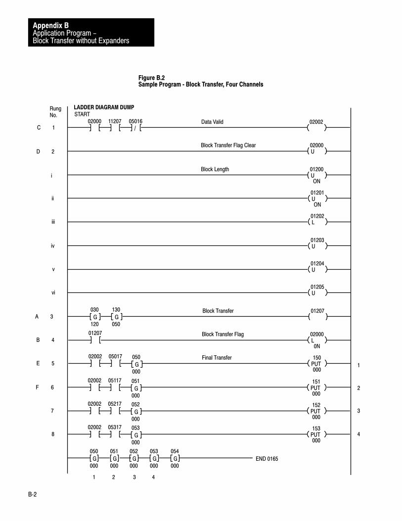
Application Program -Block Transfer without Expanders
Appendix B
B�2
Figure B.2 Sample Program � Block Transfer, Four Channels
PUT
02002 150
000
Final Transfer05017 050
000G
01207Block Transfer130
050G
030
120G
1
RungNo.
L
01207 02000
0N
Block Transfer Flag
U02000Block Transfer Flag Clear
PUT
02002 151
000
05117 051
000G
PUT
02002 152
000
05217 052
000G
PUT
02002 153
000
05317 053
000G
U01200
ON
Block Length
U01201
ON
L01202
U01203
U01204
U01205
02000 02002Data Valid11207 05016/
050
000G
051
000G
052
000G
053
000G
054
000G END 0165
START LADDER DIAGRAM DUMP
C
1 2 3 4
2D
i
ii
iii
iv
v
vi
3A
4B
5E
6F
7
8
1
2
3
4

Application Program -Block Transfer without Expanders
Appendix B
B�3
The following paragraphs define each of the rungs in the sample programof Figure B.2:
SCAN 1
A, Rung 3Block Transfer 01207
Preconditioning of this block transfer loadmap rung is optional (11111 isoptional). First, Timer and Counter Accumulated Area 030 stores ModuleLocation 120. Timer and Counter Preset Area 130 stores Data TablePointer 050. Output Bit 01207 initiates block transfer. The three channelsof data are input according to Table B.A.
B, Rung 4Block Transfer Flag 02000
Bit 01207 is examined to determine if a block transfer was initiated. Bit 02000 is latched so that this information can be maintained until thenext program scan.
Table B.AChannels of Data Words (Block Transfer)
Channel 1 Word 050
Channel 2 Word 051
Channel 3 Word 052
Channel 4 Word 053
SCAN 2
C, Rung 1Data Valid 02002
This rung determines if a block transfer was requested and completedduring the I/O scan. Additionally, Bit 16 is examined to assure that nomodule fault exists. If the transfer occurred and no module fault exists,Bit 02002 is set (data okay).
Sample Program

Application Program -Block Transfer without Expanders
Appendix B
B�4
D, Rung 2Block Transfer Flag Clear 02000
Bit 02000 is reset (unlatched) and will be set if a block transfer request ismade this program scan (Rung 4).
E, Rung 5Final Transfer 150
Based on the fact that Bit 02002 is set and Bit 17 is true (1), the data inWord 050 is transferred to Word 150. (Bit 17 is examined to insure thatthis channel has valid data. Word 050 is a buffer for Channel 1 data.) Thedata in Word Location 150 may now be used in the program.
F, Rung 6Final Transfer 151
Each channel of 1 through 4 must have its data buffered. This may beaccomplished by storing the valid data in another word or preconditioninga rung with a Data Okay Bit 02002 and Data Valid Bit XXX17.
The four channels of data are stored according to Table B.B.
Table B.BChannels of Data Storage (Block Transfer)
Buffer Valid Data
Channel 1 Word 050 Word 150
Channel 2 Word 051 Word 151
Channel 3 Word 052 Word 152
Channel 4 Word 053 Word 153
The read bit in the output word to the module must be set in order forblock transfer to occur. The simplest way to turn this bit on is to make itthe output bit of the rungs. The first digit of the output address is zero,because it is in the output image table. The next three digits are themodule’s rack address (rack number and group). The rack address mustbe the same as the address loaded into the lower GET. The last digit, 7, isthe bit in the word that signals the module to begin the transfer. For thismodule, the Bit 7 is the signal for a read operation.

Application Program -Block Transfer without Expanders
Appendix B
B�5
There should be one program rung for each module. One word should beleft empty (or set to 000) between the last block transfer lower GET (theGETs containing the module’s address) and the first use of the timer andcounter area for normal operations (timers, counter, etc.). Also, the lastfour bits (Bits 14 through 17) of the loadmap GETs should always be 000.Since the BCD format uses only the first 12 bits, this will normally be thecase.

Appendix
C
C�1
Application Program �Block Transfer with Expanders
This appendix provides a workable block transfer application program forprogramming a PLC-2/30, Mini-PLC-2/15, or PLC-3 ProgrammableController to access an Analog Input Module that has associated ExpanderModules. The “Sample Program” that follows is designed toaccommodate the 22-channel hardware configuration shown inFigure C.1. “Overview” provides an overview of the principles involvedin the “Sample Program” detailed below.
Figure C.1Hardware Configuration, 22 Channels
Analog InputModule
BackplaneBus
To PLCProcessor
AnalogCables
Expander 1
Expander 2
Expander 3
1-8
1-6
1-3
22Channels
CH 1
CH 2
CH 4
CH 5
CH 6
CH 7
CH 8
CH 3
10485
General

Application Program -Block Transfer with Expanders
Appendix C
C�2
The program shown in Figure C.2 and defined in detail in “SampleProgram” directs the PC processor to perform block transfer. Blocktransfer from the Analog Input Module to initial storage word locations isaccomplished entirely by the block transfer rung. When block transfer iscomplete and the transferred value words are declared valid, the 22 valuewords are transferred from their initial storage word locations to theirfinal storage word locations by the file-to-file move rungs.
The following paragraphs define each of the rungs in the sample programof Figure C.2.
Rungs 1�3Expander Fault Bits 02500�02502
The diagnostic bit for Channel 1 of each expander is examined for an ONcondition. If 30016 is ON, Bit 02500 is latched ON, indicating a faultassociated with Expander 1. If Expander 2 is faulted, Bit 02501 will belatched ON. The user should reset these bits (02500, 02501, and 02502)after the fault is corrected.
Rung 4Block Transfer 030
Master module (1771-IF, Master 1) is located in Rack 1, Module Group 4. Block Length = 22 (E1: 8 inputs; E2: 6 inputs; E3: 3 inputs;Remaining Channels on Master Module: 5 inputs). Temporary analogvalues to be stored in Words 300-325. Enable Bit 01407, Done Bit 11047.
Rung 5Watchdog Timer 230
Block Transfer Enable Bit 01407, when ON, starts Timer 230. Timer 230has a preset of 100 ms. If the block transfer done bit (11407) does notcome on within 100 ms, Bit 02600 will be latched ON (Rung 7). Thepreset value will be different depending on the application (user shouldselect preset value according to system design).
Overview
Sample Program

Application Program -Block Transfer with Expanders
Appendix C
C�3
Figure C.2Sample Program � Block Transfer, 22 Channels
L
300
16
025
ON 00
Expander Fault Bits
PR 010AC 000
1
START
LADDER DIAGRAM DUMP
Rung No.
BLOCK XFER READData Address:Module Address:Block Length:
030140
22File: 300-325
EN014
07
DN114
07
L
310
16
025
ON 01
L
316
16
025
ON 02Block Transfer
TON014
07
230
.01
Watchdog Timer
FILE TO FILE MOVECounter Address:Position:File Length:
031008008
File A:File R:Rate per Scan:
300-307400-407
008
EN114
07
031
17
300
16/
300
17
DN031
15
File to File Move
CTR114
07
230Timer Reset
PR 010AC 000
L230
15
026
OFF 00
Flag Bit
FILE TO FILE MOVECounter Address:Position:File Length:
032006006
File A:File R:Rate per Scan:
310-315410-415
006
EN
114
07
032
17
310
16/
310
17
DN032
15
File to File Move
FILE TO FILE MOVECounter Address:Position:File Length:
033003003
File A:File R:Rate per Scan:
316-320416-420
003
EN114
07
033
17
316
16/
316
17
DN033
15
File to File Move
2
3
4
5
6
7
8
9
10

Application Program -Block Transfer with Expanders
Appendix C
C�4
Figure C.2Sample Program � Block Transfer, 22 Channels Continued
400
563G
401
563G
402
563G
403
563G
404
563G
405
563G
406
563G
407
563G
Display Only
FILE TO FILE MOVECounter Address:Position:File Length:
034005005
File A:File R:Rate per Scan:
321-325421-425
005
EN114
07
034
17
321
16
321
17
DN034
15
020
01
11
Rung No.
410
093G
411
093G
412
093G
413
093G
414
093G
415
093G
020
02
416
844G
417
844G
420
844G
020
03
421
657G
422
469G
423
375G
424
281G
425
375G
020
04
12
13
14
15
END 00479
/
Rung 6Timer Reset 230
When block transfer done bit is ON, Timer 230 is reset.
Rung 7Flag Bit 02600
If Timer 230 Done Bit (23015) is ON, Bit 02600 is latched ON. Thislatched-ON bit will alert the user that block transfer has not occurred ortook longer than 100 ms to complete. (The preset value of 100 ms isapplication dependent.)
Rung 8File�to�File Move 031
This rung transfers valid analog data from Expander 1 block transfer filewords (300-307) to final storage words (400-407). The file-to-file moveinstruction is preconditioned with Bit 11407 (BT done bit), Bit 30016

Application Program -Block Transfer with Expanders
Appendix C
C�5
(Channel 1, Expander 1 diagnostic bit), and Bit 30017 (Channel 1,Expander 1 data valid bit). The file length (file-to-file move instruction)should equal the number of inputs to that Expander, and the rate per scanshould equal the file length.
Rungs 9�11 File�to�File Move 032�034
These three rungs perform the same operations as Rung 8, except thatRung 9 is associated with Expander 2; Rung 10 is associated withExpander 3; and Rung 11 is associated with Channels 4 through 8 on theAnalog Input Module.
Rungs 12�15Display Only 02001�02004
These rungs have no affect on program operation. They provide a meansof displaying the final valid analog values. Rung 12 displays Expander 1analog values. Rung 13 displays Expander 2 analog values. Rung 14displays Expander 3 analog values. Rung 15 displays analog values fromChannels 4 through 8 on the Analog Input Module.

Appendix
D
D�1
Application Programs �Single Transfer without Expanders
This appendix provides three workable single-transfer applicationprograms for programming a PC processor to access an Analog InputModule that has no associated Expander modules. The sample programsin “PLC-2” and “PLC” are designed to accommodate the fullcomplement, eight-channel hardware configuration shown in Figure D.1.“PLC-2” describes two single-transfer programs for PLC-2 FamilyProcessors, and “PLC” describes one single-transfer program for PLCprocessors.
Figure D.1Hardware Configuration, Eight Channels
Analog Input Module
BackplaneBus
To PLC-2FamilyProcessoror PLCProcessoror PLC-3Processor
1
2
3
4
5
6
7
8
CH 1
CH 2
CH 3
CH 4
CH 5
CH 6
CH 7
CH 8
10488
“Continuous Update” describes a sample program for continuous update.“Immediate Update” describes a sample program for immediate update.
“Overview” below provides an overview of the sample program shown inFigure D.2 and detailed in “Sample Program” below.
General
PLC�2
Continuous Update

Application Programs -Single Transfer without Expanders
Appendix D
D�2
OVERVIEW
The sample program in Figure D.2 provides one channel-select rung andone channel-transfer rung for each of the eight channels. Each secondprogram scan enables a different channel-select rung, initiating theAnalog Input Module to forward that channel’s value word to I/O InputImage Table Word Location 112. Each alternate program scan enables thechannel-transfer rung corresponding to the last channel-value wordforwarded to 112. Provided Data Value Bit 11217 and Diagnostic Bit 11216 are ON and OFF, respectively, the value word residing in 112 istransferred to a final storage word location of 050 through 057.
SAMPLE PROGRAM
The following paragraphs define each of the rungs in the sample programshown in Figure D.2:
Rungs 1�2Scan Counter 040
Counter 040 increments by one count at each program scan, and it is resetto count zero by Rung 19 when its accumulated count reaches PresetValue (PR) 17.
Rung 3Channel 1 Select 01200
When Counter 040’s accumulated count equals 001 (Scan 1) and 002(Scan 2), Output Image Table Bit 01200 is set to ON, thus selectingChannel 1 of the Analog Input Module residing in Rack 1, Group 2, Slot 0.
Rung 4Channel 1 Transfer 050
When Counter 040’s accumulated count equals 003 (Scan 3), the Channel 1 value word in Input Image Table Word Location 112 istransferred to Final Storage Word Location 050, provided Data Valid Bit 11217 is ON and Diagnostic Bit 11216 is OFF.
Odd Rungs 5�17Channels 2�8 Select 01201�01207
Same as Rung 3, except apply to Channels 2 through 8.

Application Programs -Single Transfer without Expanders
Appendix D
D�3
Figure D.2Sample Program � Single Transfer, Continuous Update, 8 Channels, PLC�2
CTU040Scan Counter
PR 017AC 000
01200Channel 1 Select041
001=
040
000G
1
Rung No.
CTU040
PR 017AC 000
2
3
4
5
6
7
8
9
10
042
002=
01201Channel 2 Select043
003=
040
000G
044
004=
01202Channel 3 Select045
005=
040
000G
046
006=
01203Channel 4 Select047
007=
040
000G
060
008=
PUT
11217 050
000
Channel 1 Transfer11216
/040
000G
043
003=
112
000G
PUT
11217 051
000
Channel 2 Transfer11216
/040
000G
045
005=
112
000G
PUT
11217 052
000
Channel 3 Transfer11216
/040
000G
047
007=
112
000G
PUT
11217 053
000
Channel 4 Transfer11216
/040
000G
061
009=
112
000G
START
LADDER DIAGRAM DUMP

Application Programs -Single Transfer without Expanders
Appendix D
D�4
Figure D.2Sample Program � Single Transfer, Continuous Update, 8 Channels, PLC�2 Continued
01204Channel 5 Select061
009=
040
000G
062
010=
PUT11217 054
000
Channel 5 Transfer11216/
040
000G
063
011=
112
000G
01205Channel 6 Select063
011=
040
000G
064
012=
PUT11217 055
000
Channel 6 Transfer11216/
040
000G
065
013=
112
000G
01206Channel 7 Select065
013=
040
000G
066
014=
PUT11217 056
000
Channel 7 Transfer11216/
040
000G
067
015=
112
000G
01207Channel 8 Select067
015=
040
000G
070
016=
PUT11217 057
000
Channel 8 Transfer11216/
040
000G
071
017=
112
000G
PR 017AC 000
CTR04015 040Scan Counter Reset
Rung No.
050
000G
051
000G
052
000G
053
000G
054
000G
055
000G
056
000G
057
000G END 0245
Display Only
11
12
13
14
15
16
17
18
19
20

Application Programs -Single Transfer without Expanders
Appendix D
D�5
Even Rungs 6�18Channels 2�8 Transfer 051�057
Same as Rung 4, except apply to Channels 2 through 8.
Rung 19Scan Counter Reset 050�057
See Rungs 1-2.
Rung 20Display Only 050�057
This rung has no effect on program operation. It provides a means ofdisplaying the final valid analog values.
“Overview” below provides an overview of the sample program shown inFigure D.3 and detailed in “Sample Program” below.
OVERVIEW
The immediate update program in Figure D.3 is similar to the“Continuous Update” program. The immediate update program includesan IMMEDIATE INPUT instruction in Rung 4 which enables eachprogram scan to select a channel and store the previously selectedchannel’s value word. In the continuous update program, every other scanselects a channel and stores the previously selected channel’s value word.
SAMPLE PROGRAM
The following paragraphs define each of the rungs in the sample programshown in Figure D.3:
Immediate Update

Application Programs -Single Transfer without Expanders
Appendix D
D�6
Figure D.3Sample Program � Single Transfer, Immediate Update, 8 Channels, PLC�2
CTU040Scan Counter
PR 008AC 000
1
CTU040
PR 008AC 000
2
START
LADDER DIAGRAM DUMPRung No.
01201Channel 2 Select041
001=
040
000G
PUT
11217 051
000
Channel 2 Transfer11216
/040
000G
042
002=
112
000G
CTR
04015 040Scan Counter Reset
PUT
11217 050
000
Channel 1 Transfer11216
/040
000G
041
001=
112
000G
112
I
PR 008AC 000
01202Channel 3 Select042
002=
040
000G
PUT
11217 052
000
Channel 3 Transfer11216
/040
000G
043
003=
112
000G
01203Channel 4 Select043
003=
040
000G
PUT
11217 053
000
Channel 4 Transfer11216
/040
000G
044
004=
112
000G
01204Channel 5 Select044
004=
040
000G
PUT
11217 054
000
Channel 5 Transfer11216
/040
000G
045
005=
112
000G
01205Channel 6 Select045
005=
040
000G
PUT
11217 055
000
Channel 6 Transfer11216
/040
000G
046
006=
112
000G
3
4
5
6
7
8
9
10
11
12
13
14

Application Programs -Single Transfer without Expanders
Appendix D
D�7
Figure D.3Sample Program � Single Transfer, Immediate Update, 8 Channels, PLC�2 Continued
01206Channel 7 Select046
006=
040
000G
PUT
11217 056
000
Channel 7 Transfer11216
/040
000G
047
007=
112
000G
01207Channel 8 Select047
007=
040
000G
PUT
11217 057
000
Channel 8 Transfer11216
/040
000G
060
000=
112
000G
01200Channel 1 Select060
000=
040
000G
15
16
17
18
19
I0T012Display Only
Rung No.
050
000G
051
000G
052
000G
053
000G
054
000G
055
000G
056
000G
057
000G END 0215
20
21
Rungs 1�3Scan Counter 040
Counter 040 increments by one count at each program scan, and it is resetto count zero by Rung 3 when its accumulated count reaches Preset Value(PR) 8.
Rung 4Channel 1 Transfer 050
Channel 1 has been selected on the previous scan by Rung 19.IMMEDI ATE UPDATE instruction of this Rung 4 directs processor totransfer Channel 1 value word from Analog Input Module to Input ImageTable Word Location 112. When Scan Counter 040’s accumulated countequals 001 (Scan 2), the remainder of the instructions of this Rung 4direct the processor to transfer the value word from 112 to Final StorageWord Location 050, provided Data Valid Bit 11217 and Diagnostic Bit 11216 are ON and OFF, respectively.

Application Programs -Single Transfer without Expanders
Appendix D
D�8
Rung 5Channel 2 Select 01201
When Counter 040’s accumulated count equals 001 (Scan 2), outputImage Table Bit 01201 is set to ON, thus selecting Channel 2 of theAnalog Input Module residing in Rack 1, Group 2, Slot 0.
Rung 6Channel 2 Transfer 051
When Counter 040’s accumulated count equals 002 (Scan 3), the Channel 2 value word in Input Image Table Word Location 112 istransferred to Final Storage Word Location 051, provided Data Valid Bit 11217 is ON and Diagnostic Bit 11216 is OFF. (Channel 2 wasselected during Scan 2 by Rung 5, and the resultant asserted value wordwas transferred from the Analog Input Module to 112 by direction ofRung 4 IMMEDIATE INPUT instruction during Scan 3.)
Odd Rungs 7�17Channel 3�8 Select 01202�01207
Rung 19Channel 1 Select 01200
Same as Rung 5, except apply to Channels 3 through 8 and 1.
Even Rungs 8�16Channel 3�8 Transfer 052�057
Same as Rung 6, except apply to Channels 3 through 8.
Rungs 20�21Display Only 050�057
These rungs have no effect on program operation. They provide a meansof displaying the final analog values.
“Overview” below provides an overview of the sample program shown in Figure D.4 and detailed in “Sample Program” below.
PLC

Application Programs -Single Transfer without Expanders
Appendix D
D�9
OVERVIEW
The program in Figure D.4 sequentially transfers the Channel 1 throughChannel 8 value words from the Analog Input Module to itscorresponding Input Image Table Word Location 110 and, if valid,transfers them to final storage word locations.
SAMPLE PROGRAM
The following paragraphs define each of the rungs in the sample programshown in Figure D.4:
Rungs 1�2Initialization 0200, 0100
When the processor is in the run or program mode, Bit 32200 (Rung 4) isOFF. When the processor is placed in the run mode, Bit 32200 remainsOFF until set to on by Rung 4. During the first scan after the run mode isentered; therefore, Bit 32200 is OFF until the scan reaches Rung 4.During the first part of the initial scan up to Rung 4, Rung 1 resets allChannel 1-8 Control Bits 20000 through 20007 to OFF and Rung 2 resetsall Output Image Table Bits 01000 through 01007 (channel select bits) toOFF.
Rung 3Channel 1 Select 01000
During the first part of the initial scan up to Rung 4, the upper branch ofRung 3 sets Output Image Table Bit 01000 to ON, selecting Channel 1.On the following scans, Rung 3 is controlled by the lower branch.
Rung 4Initialization Complete 32200
See Rungs 1-2.
Rung 5Channel 8 Control Unlatch 20007
This rung unlatches the control bit (20007) corresponding to thepreviously transferred channel (Channel 8). (This bit is already OFFduring the initial scan.)

Application Programs -Single Transfer without Expanders
Appendix D
D�10
Figure D.4Sample Program � Single Transfer, 8 Channels, PLC
L
01000 20000
OFF
Channel 1 Control11017 11016
/
PUT
32200 0200
000/
Initialization0201
000G
PUT
20000 0300
000
Channel 1 Transfer01000
U
01000 20007Channel 8 Control Unlatch
Rung No.
1
32200Initialization Complete
L
20000 01001
OFF
Channel 2 Select11017
/
PUT
32200 0010
000/
Initialization0201
000G
0110
000G
L
32200 01000
OFF/
Channel 1 Select11016
/
20007 11017
/
U
20000 01000Channel 1 Select Unlatch
U01001 20000Channel 1 Control Unlatch
L01001 20001
OFF
Channel 2 Control11017 11016/
PUT20001 0301
000
Channel 2 Transfer01001 0110
000G
U20001 01001Channel 2 Select Unlatch
L20000 01002
OFF
Channel 3 Select11017/
U01002 20001Channel 2 Control Unlatch
2
3
4
5
6
7
8
9
10
11
12
13
14
15
START

Application Programs -Single Transfer without Expanders
Appendix D
D�11
Figure D.4Sample Program � Single Transfer, 8 Channels, PLC Continued
PUT
20002 0302
000
Channel 3 Transfer01002
L
20002 01003
OFF
Channel 4 Select11017
/
0110
074G
U
20002 01002Channel 3 Select Unlatch
U01003 20002Channel 3 Control Unlatch
L
01003 20003
OFF
Channel 4 Control11017 11016
/
PUT
20003 0303
000
Channel 4 Transfer01003 0110
074G
U
20003 01003Channel 4 Select Unlatch
L
20003 01004
OFF
Channel 5 Select11017
/
16
17
18
19
20
21
22
23
24
L
01002 20002
OFF
Channel 3 Control11017 11016
/
U
01004 20003Channel 4 Control Unlatch
L
01004 20004
OFF
Channel 5 Control11017 11016
/
PUT
20004 0304
000
Channel 5 Transfer01004 0110
074G
U20004 01004Channel 5 Select Unlatch
L20004 01005
OFF
Channel 6 Select11017/
26
27
28
29
25
U01005 20004Channel 5 Control Unlatch
30
Rung No.

Application Programs -Single Transfer without Expanders
Appendix D
D�12
Figure D.4Sample Program � Single Transfer, 8 Channels, PLC Continued
PUT20005 0305
000
Channel 6 Transfer01005 0110
074G
U20005 01005Channel 6 Select Unlatch
L20005 01006
OFF
Channel 7 Select11017/
32
33
34
U01006 20005Channel 6 Control Unlatch
L01006 20006
OFF
Channel 7 Control11017 11016/
PUT20006 0306
000
Channel 7 Transfer01006 0110
074G
U20006 01006Channel 7 Select Unlatch
L20006 01007
OFF
Channel 8 Select11017/
36
37
38
39
35
U01007 20006Channel 7 Control Unlatch
40
L01007 20007
OFF
Channel 8 Control11017 11016/41
PUT20007 0307
000
Channel 8 Transfer01007 0110
000G
U20007 01007Channel 8 Select Unlatch
42
43
Rung No.
L01005 20005
OFF
Channel 6 Control11017 11016/31
END 01159

Application Programs -Single Transfer without Expanders
Appendix D
D�13
Rung 6Channel 1 Control 20000
During the first scan, after Channel 1 was selected by Rung 3, after theChannel 1 value word was transferred from the Analog Input Module toInput Image Table Word Location 110, this rung latches Channel 1Control Bit 20000 to ON, provided Data Valid Bit 11017 is ON andDiagnostic Bit 11016 is OFF.
Rung 7Channel 1 Transfer 0300
This rung transfers the Channel 1 value word from Input Image TableWord Location 110 to Final Storage Word Location 0300, providedChannel 1 Control Bit 20000 is set to ON.
Rung 8Channel 1 Select Unlatch 01000
This rung unlatches the Channel 1 select bit (01000).
Rungs 9�43
Same as Rungs 3 and 5-8, except apply to Channels 2 through 8.
Appendix
E
E�1
Application Program �Single Transfer with Expanders
This appendix provides a single-transfer application program forprogramming a PC processor to access an Analog Input Module that hasassociated Expander Modules. The sample program below is designed toaccommodate the full-complement, 64-channel hardware configurationshown in Figure E.1. This configuration uses a full complement of eight1771-E1 Expanders, each using a full complement of eight input channels.
The section titled “Less than Eight Expanders” gives instructions formodifying the full-complement program to accommodate a hardwareconfiguration that uses less than eight Expanders. The section titled “Lessthan Eight Expander Channels” gives instructions for modifying thefull-complement program (modified or not in accordance with “Less thanEight Expanders”) to accommodate a hardware configuration that usesless than eight inputs on each of one or more Expanders.
The program provided in “Sample Program” and modified in accordancewith ”Less than Eight Expanders” and ”Less than Eight ExpanderChannels” to correspond to the user’s hardware configuration willimplement single-transfer interface correctly, provided the configurationhas been programming-plug conditioned and connected correctly inaccordance with Chapter 2 of this manual.
“Overview” provides an overview of the principles involved in the“Sample Program” detailed below.
The program shown in Figure E.2 and defined in detail in “SampleProgram” directs the PC processor to perform the following sequence ofoperations for each of the 64 channels, one at a time.
Select the Expander Select the Channel [The word of the selected channel is then transferred
from the Analog Input Module to the module’s associated input imagetable word location (114 in this example).]
Examine the value word’s data valid and diagnostic status bits. Store the value word if the data valid and diagnostic bits are ON and
OFF respectively.
General
Overview

Application Program -Single Transfer with Expanders
Appendix E
E�2
Select
The expander counter rung, channel counter rung, expander-select bitrungs, and channel-select bit and channel-select unlatch rungs are used toselect the 64 channels one at a time. The channel counter is incrementedby one count after each channel has been single transferred. Theexpander counter is incremented by one count after each eight channelshave been single transferred. Both counters start at Count 1 and are resetto Count 1 by the eighth increment thereafter. At any given time thecount in the expander counter selects one of the expander select rungs,enabling it to write a corresponding expander-select bit into the outputimage table word (014) of the Analog Input Module. At the same time,the count in the channel counter selects one of the channel-select latchrungs, enabling it to write a corresponding channel-select bit into the sameoutput image table word. During the output image table scan, thechannel-select word is transferred from Output Image Table WordLocation 014 to the Analog Input Module, completing the channelselection.
Transfer
On the next or some later program scan, depending on how long theAnalog Input Module’s on-board microcomputer requires to respond tothe channel-select word, the Analog Input Module responds by assertingthe selected channel’s value word. During the input image table scan ofthe same program scan the asserted value word is transferred to InputImage Table Word Location 114. Bits 16 and 17 of that word are thediagnostic and data valid bits, respectively.
Examine
During the first program scan after the value word is transferred to theinput image table, copies of the data valid and diagnostic bits are cachedin bit storage locations by the data valid bit and diagnostic bit rungs. Ifthe cached data valid and diagnostic bits are ON and OFF respectively,one of the expander valid bit rungs will set a storage bit (expander validbit) corresponding to the selected Expander.
Store
In accordance with the expander valid bit (if it is ON) and the channelselect latch bit, the corresponding final analog storage rung will transferthe value word to a storage word location.

Application Program -Single Transfer with Expanders
Appendix E
E�3
Figure E.1Hardware Configuration, 64 Channels
Analog InputModule
Backplane
Bus
To PLC
Processor
AnalogCables
Expander 1
64
Channels
1
2
3
4
5
6
7
8
1�8
1�8
Expander 2
Expander 3
Expander 4
Expander 5
Expander 6
Expander 7
Expander 8
CH 2
CH 3
CH 4
CH 5
CH 6
CH 7
CH 8
CH 1
1�8
1�8
1�8
1�8
1�8
CH 1
CH 2
CH 3
CH 4
CH 5
CH 6
CH 7
CH 8
10496

Application Program -Single Transfer with Expanders
Appendix E
E�4
The following paragraphs define each of the rungs in the sample programshown in Figure E.2:
Rung 1Data Valid Bit 11417, 20110
Bit 20100 is a storage bit for Data Valid Bit 11417. The storage bit isnecessary in order to maintain the state of Bit 11417 throughout theprogram.
Rung 2Diagnostic Bit 11416, 20005
Bit 20005 is a storage bit for Diagnostic Bit 11416. The storage bit isnecessary in order to maintain the state of Bit 11416 throughout theprogram.
Rungs 3�10Expander Fault Bits 22000�22007
When Expander 1 (01410) is faulted, Storage Bit 22000 will be latchedON. When Expander 2 is faulted, Storage Bit 22001 will be latched ON,etc. The user should reset the storage bit to zero after the fault iscorrected.
Rungs 11�13Initialization 230, 232, 014
These rungs are true for one scan following power-up and during the firstscan after switching from run to program. When the rungs are true,zeroes are put into Channel Counter 230, Expander Counter 232, andAnalog Select Word 014.
Rung 14Channel Counter 230
The Channel Counter will increment when Data Valid Bit 20110 is ON orthe channel counter accumulated value equals zero. The preset valueshould equal the maximum number of channels used on the Expandersplus one count (reset count). The preset value should never be greaterthan 9. Maximum number of channels on any one Expander is 8 (8 +Reset Count = 9).
Sample Program

Application Program -Single Transfer with Expanders
Appendix E
E�5
Rung 15Expander Counter 232
The expander counter will increment when the accumulated value equalszero or when Data Valid Bit 20110 is OFF and Channel Counter Done Bit 03015 is ON or when Diagnostic Bit 20005 is ON. The preset valueshould equal the number of Expanders plus one count to reset (total of 9counts for this example).
Rungs 16�31Expander Select Bits 01410�01417
When the accumulated value of the expander counter equals 1, Expander 1 (01410) is latched ON. When the accumulated value equals2, Expander 1 (01410) is unlatched and Expander 2 (01411) is latchedON. The same procedure is followed for all eight Expanders.
Rungs 32�39Expander Storage Bits 20100�20107
When Expander 1 (01410) is selected and Data Valid Bit 20110 is ON,and Diagnostic Bit 20005 is OFF, Storage Bit 20100 is energized. Thestorage bit is used later in the program as a condition before transfer ofvalid data to final storage words. The same procedure is used for all eightExpanders.
Rungs 40�47Channel Select Bits 01400�01407
When Channel Counter 230 equals 1, Data Valid Bit 20110 is OFF and theprevious channel (01407 in this case) is OFF (unlatched). Then Channel1 (01400) will be latched ON. The same procedure is followed for alleight channels.
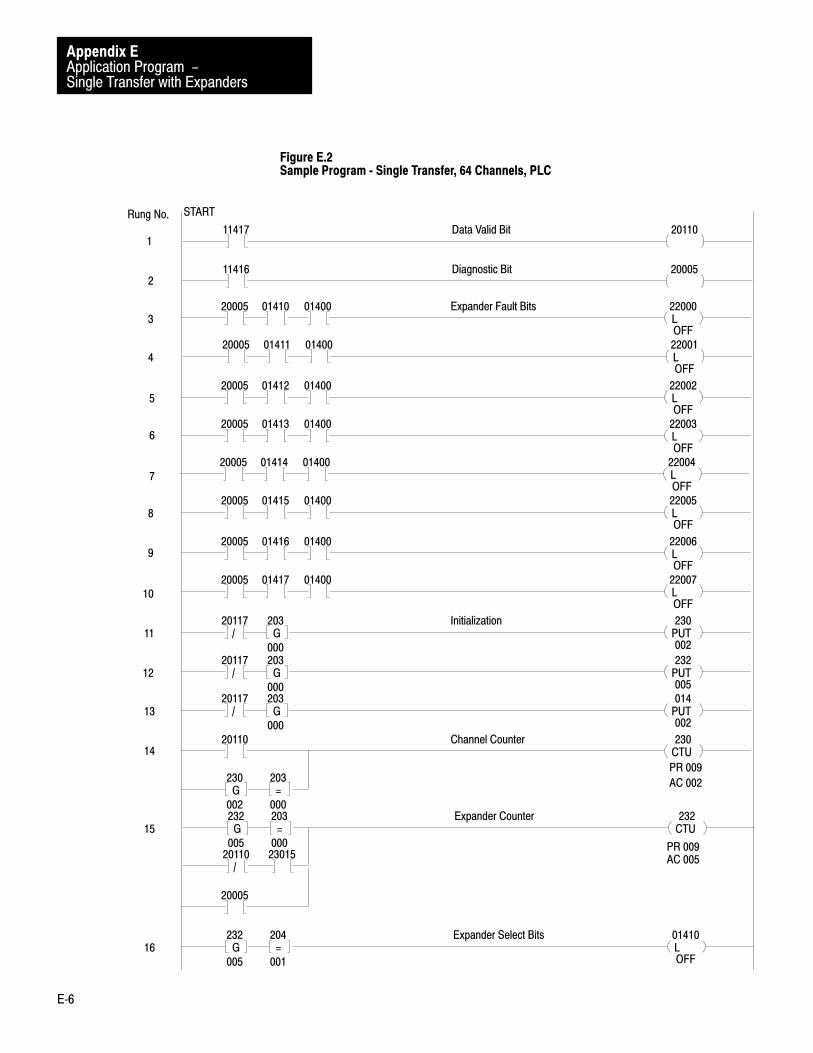
Application Program -Single Transfer with Expanders
Appendix E
E�6
Figure E.2Sample Program � Single Transfer, 64 Channels, PLC
11417 20110Data Valid Bit
11416 20005Diagnostic Bit
L20005 22000
OFF
Expander Fault Bits01410 01400
L20005 22001
OFF
01411 01400
L20005 22002
OFF
01412 01400
L20005 22003
OFF
01413 01400
L20005 22004
OFF
01414 01400
L20005 22005
OFF
01415 01400
L20005 22006
OFF
01416 01400
L20005 22007
OFF
01417 01400
PUT20117 230
002/
Initialization203
000G
PUT20117 232
005/
203
000G
PUT20117 014
002/
203
000G
CTU20110 230Channel Counter
L01410
OFF
Expander Select Bits204
001=
232
005G
CTU232Expander Counter203
000=
232
005G
PR 009
AC 002203
000=
230
002G
20110PR 009AC 005
/23015
20005
START
1
2
3
4
5
6
7
8
9
10
11
12
13
14
16
15
Rung No.

Application Program -Single Transfer with Expanders
Appendix E
E�7
Figure E.2Sample Program � Single Transfer, 64 Channels, PLC Continued
U01410205
002=
232
005G
L01411
OFF
205
002=
232
005G
U01411206
003=
232
005G
L01412
OFF
206
003=
232
005G
U01412207
004=
232
005G
L01413
OFF
207
004=
232
005G
U01413210
005=
232
005G
L01414
ON
210
005=
232
005G
U01414211
006=
232
005G
L01415
OFF
211
006=
232
005G
U01415212
007=
232
005G
L01416
OFF
212
007=
232
005G
U01416213
008=
232
005G
L01417
OFF
213
008=
232
005G
U01417214
009=
232
005G
01410 20100Expander Storage Bits20110 20005/
01411 2010120110 20005/
01412 2010220110 20005/
01413 2010320110 20005/
17
18
19
20
21
22
23
24
25
26
27
28
29
30
31
32
33
34
35
Rung No.

Application Program -Single Transfer with Expanders
Appendix E
E�8
Figure E.2Sample Program � Single Transfer, 64 Channels, PLC Continued
01414 2010420110 20005/
01415 2010520110 20005/
01416 2010620110 20005/
01417 2010720110 20005/
36
37
38
39
L20110 01400
OFF/
Channel Select Bits01407/
204
001=
230
002G
L20110 01401
ON/
01400/
205
002=
230
002G
L20110 01402
OFF/
01401/
206
003=
230
002G
L20110 01403
OFF/
01402/
207
004=
230
002G
L20110 01404
OFF/
01403/
210
005=
230
002G
L20110 01405
OFF/
01404/
211
006=
230
002G
L20110 01406
OFF/
01405/
212
007=
230
002G
L20110 01407
OFF/
01406/
213
008=
230
002G
40
41
42
43
44
45
46
47
PUT20100 400
562
Final Value Word Storage01400 114
000G
PUT20100 401
562
01401 114
000G
PUT20100 402
562
01402 114
000G
PUT20100 403
562
01403 114
000G
PUT20100 404
562
01404 114
000G
PUT20100 405
562
01405 114
000G
PUT20100 406
562
01406 114
000G
48
49
50
51
52
53
54
Rung No.

Application Program -Single Transfer with Expanders
Appendix E
E�9
Figure E.2Sample Program � Single Transfer, 64 Channels, PLC Continued
55 PUT20100 407
562
01407 114
000G
PUT20101 410
093
01400 114
000G
PUT20101 411
093
01401 114
000G
PUT20101 412
093
01402 114
000G
PUT20101 413
093
01403 114
000G
PUT20101 414
093
01404 114
000G
PUT20101 415
093
01405 114
000G
PUT20101 416
093
01406 114
000G
PUT20101 417
093
01407 114
000G
PUT20102 420
844
01400 114
000G
PUT20102 421
844
01401 114
000G
PUT20102 422
844
01402 114
000G
PUT20102 423
844
01403 114
000G
PUT20102 424
844
01404 114
000G
PUT20102 425
844
01405 114
000G
PUT20102 426
844
01406 114
000G
PUT20102 427
844
01407 114
000G
PUT20103 430
657
01400 114
000G
PUT20103 431
657
01401 114
000G
56
57
58
59
60
61
62
63
64
65
66
67
68
69
70
71
72
73
Rung No.

Application Program -Single Transfer with Expanders
Appendix E
E�10
Figure E.2Sample Program � Single Transfer, 64 Channels, PLC Continued
PUT20103 432
657
01402 114
000G74
PUT20103 433
657
01403 114
000G75
PUT20103 434
657
01404 114
000G76
PUT20103 435
657
01405 114
000G77
PUT20103 436
657
01406 114
000G78
PUT20103 437
657
01407 114
000G79
PUT20104 440
468
01400 114
000G80
PUT20104 441
468
01401 114
000G81
PUT20104 442
468
01402 114
000G82
PUT20104 443
468
01403 114
000G83
PUT20104 444
468
01404 114
000G84
PUT20104 445
468
01405 114
000G85
PUT20104 446
468
01406 114
000G86
PUT20104 447
468
01407 114
000G87
PUT20105 450
373
01400 114
000G88
PUT20105 451
373
01401 114
000G89
PUT20105 452
373
01402 114
000G90
PUT20105 453
373
01403 114
000G91
Rung No.

Application Program -Single Transfer with Expanders
Appendix E
E�11
Figure E.2Sample Program � Single Transfer, 64 Channels, PLC Continued
PUT20105 454
373
01404 114
000G 92
PUT20105 455
373
01405 114
000G 93
PUT20105 456
373
01406 114
000G 94
PUT20105 457
373
01407 114
000G 95
PUT20106 460
281
01400 114
000G 96
PUT20106 461
281
01401 114
000G 97
PUT20106 462
281
01402 114
000G 98
PUT20106 463
281
01403 114
000G 99
PUT201006 464
281
01404 114
000G100
PUT20106 465
281
01405 114
000G101
PUT20106 466
281
01406 114
000G102
PUT20106 467
281
01407 114
000G103
PUT20107 470
285
01400 114
000G104
PUT20107 471
846
01401 114
000G105
PUT20107 472
752
01402 114
000G106
PUT20107 473
098
01403 114
000G107
PUT20107 474
191
01404 114
000G
108
PUT20107 475
472
01405 114
000G109
Rung No.
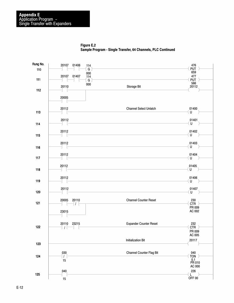
Application Program -Single Transfer with Expanders
Appendix E
E�12
Figure E.2Sample Program � Single Transfer, 64 Channels, PLC Continued
PUT20107 476
659
01406 114
000G110
TON030
15
040
0.1/
Channel Counter Flag Bit
PUT20107 477
566
01407 114
000G
20110 20112Storage Bit
U20112 01400Channel Select Unlatch
U20112 01401
U20112 01402
U20112 01403
U20112 01404
U20112 01405
U20112 01406
U20112 01407
CTR20005 230Channel Counter Reset20110
/
23015
CTR20110 232Expander Counter Reset23215
/PR 009AC 005
20117Initialization Bit
PR 010AC 000
L040
15
226
OFF 00
111
112
113
114
115
116
117
118
119
120
121
122
123
124
125
11
PR 009AC 002
11
112
113
114
115
116
117
118
119
120
121
122
123
124
125
Rung No.Rung No.
20005

Application Program -Single Transfer with Expanders
Appendix E
E�13
Figure E.2Sample Program � Single Transfer, 64 Channels, PLC Continued
Rung No.
400
562
22500G
Display Only
401
562G
402
562G
403
562G
404
562G
405
562G
406
562G
407
562G
410
093
22501G
411
093G
412
093G
413
093G
414
093G
415
093G
416
093G
417
093G
420
844
22502G
421
844G
422
844G
423
844G
424
844G
425
844G
426
844G
427
844G
430
657
22503G
431
657G
432
657G
433
657G
434
657G
435
657G
436
657G
437
657G
450
373
22505G
451
373G
452
373G
453
373G
454
373G
455
373G
456
373G
457
373G
460
281
22506G
461
281G
462
281G
463
281G
464
281G
465
281G
466
281G
467
281G
470
285
22507G
471
846G
472
752G
473
098G
474
191G
475
472G
476
659G
477
566G
126
127
128
129
130
131
132
133
END 01055
440
468
22504G
441
468G
442
468G
443
468G
444
468G
445
468G
446
468G
447
468G
Rungs 48�111Final Analog Storage 400�477
Each rung represents one channel on one expander. For a full system (onemaster, 64 channels), 64 of these rungs are required. When the expanderstorage bit for Expander 1 (20100) is ON, Channel 1 Select Bit 01400 isON. Then, the analog value at Expander 1, Channel 1 is transferred toStorage Word 400 (final valid data). This procedure is followed for theremaining 63 channels.
Rungs 112Storage Bit 20112
Bit 20112 is energized when the data valid bit is ON or Diagnostic Bit 20005 is ON. Bit 20112 is a storage bit used in Rungs 113-120.

Application Program -Single Transfer with Expanders
Appendix E
E�14
Rungs 113�120Channel Select Unlatch 01400�01407
When Storage Bit 20112 is ON (i.e., when data is valid or diagnostic bit isON indicating a fault) all channels will be unlatched.
Rung 121Channel Counter Reset 230
When Diagnostic Bit 20005 is ON and the data valid bit is OFF orChannel Counter Done Bit 230015 is ON and the data valid bit is OFF, thechannel counter will reset.
Rung 122Expander Counter Reset 232
When Valid Data Bit 20110 is OFF and Expander Counter Done Bit 23215 is ON, expander counter (232) will reset.
Rung 123Initialization Bit 20117
Storage Bit 20117 is OFF for one scan only. Bit 20117 is used as acondition in the initialization rungs (11-13).
Rungs 124�125Channel Counter Flag Bit 22600
If Channel Counter Done Bit 03015 does not energize before Timer 040times out (preset should be determined by user according to systemconfiguration), Bit 22600 will be latched ON. This will indicate thatcommunication between the processor and Analog Input Module orModules has ceased.
Rungs 126�133Display Only 22500�22507
These rungs have no effect on program operation. They provide a meansof displaying the final valid analog values.
When less than eight Expanders are used in the hardware configuration,the program in Figure E.2 must be modified to account for the differencein configuration. In essence, this consists of removing all rungs that
Less Than Eight Expanders

Application Program -Single Transfer with Expanders
Appendix E
E�15
pertain to Expanders not present, modifying the channel counter andexpander counter rungs, and if remaining Analog Input Module channelsare to be used, adding rungs to treat that group of channels as anExpander.
Example: For a hardware configuration using four Expanders of eightchannels each and using remaining Analog Input Module inputs(Channels 5 through 8) as a group of single-ended inputs (Figure E.3), theprogram in Figure E.2 would be modified as follows.
1. Insert Rung A of Figure E.3 between Rungs 13 and 14 of Figure E.2.This rung resets Storage Word Location 236, which representsAnalog Input Module’s group of Channels 5 through 8.
2. Change Preset Value (PR) of Expander Counter 232 (Rung 15) tosix; four Expanders plus one for Analog Input Module’s group ofChannels 5 through 8 plus one count for reset (4 + 1 + 1 = 6 in thisexample).
3. Insert Rungs B and C, of Figure E.3 between Rungs 23 and 24. Bit 23600 represents Analog Input Module’s group of Channels 5through 8. Rungs B and C are used to latch and unlatch this group ofchannels just as Rungs 16 through 23 are used to latch and unlatchthe four Expanders.
4. Insert Rung D of Figure E.3 between Rungs 35 and 36. Just as eachExpander select bit of Rungs 16 through 23 is used as a condition toset an Expander storage bit, Expander Select Bit 23600 should beused to energize a storage bit (20104).
5. Insert an EXAMINE OFF instruction (E of Figure E.3) in each ofRungs 40 through 43. This modification to Rungs 40 through 43inhibits selection of the first four channels when data is to betransferred from Analog Input Module’s group of Channels 5through 8.
6. Insert Rung F, of Figure E.3, between Rungs 122 and 123. WhenAnalog Input Module’s group of Channels 5 through 8 is selected(Bit 23600 is latched by Rung B) and the channel counter equals 1,then the channel counter must be forced to skip over the first fourAnalog Input Module Channels. Rung F accomplishes this byloading a count of 5 into the accumulated value of the channelcounter.

Application Program -Single Transfer with Expanders
Appendix E
E�16
7. Remove unused Rungs 7 through 10, 24 through 31, 36 through 39,88 through 111, and 131 through 133.
When less than eight Expander channels are used in the hardwareconfiguration, the program in Figure E.2 or the program in Figure E.2modified in accordance with “Less than Eight Expanders” must bemodified to account for the difference in configuration. In essence, thisconsists of removing rungs that pertain to unused expander channels andmodifying rungs to inhibit selection of unused expander channels.
Example: For a hardware configuration where Expander 3 uses onlythree channels and Expander 4 uses only six channels, the program inFigure E.3 would be modified as follows.
Expander 2
1. Insert an EXAMINE OFF instruction (A of Figure E.4) in each ofRungs 43 through 47. This will inhibit selection of Channels 4through 8 of Expander 2.
2. Insert Rung B, of Figure E.4, between Rungs 122 and 123. Thisrung will force the channel counter (Rung 14) to skip over unusedChannels 4 through 8 of Expander 2.
3. Remove unused rungs of 59 through 63.
Expander 4
4. Insert an EXAMINE OFF instruction (C of Figure E.4) in each ofRungs 46 and 47. This will inhibit selection of Channels 7 and 8.
5. Insert Rung D in Figure E.4, between 122 and 123. This rung willforce the channel counter (Rung 14) to skip over unused Channels 7and 8.
6. Remove unused Rungs 78 and 79.
Less Than Eight ExpanderChannels

Application Program -Single Transfer with Expanders
Appendix E
E�17
Figure E.3Less Than Eight Expanders, Modifications
203
000
20117
PUT
236
G
210
005
232
L
23600
=G
A
B
INITIALIZATION
EXPANDER SELECT
211
006
232
U
23600
=GC
2011023600 20104
D
20005EXPANDED STORAGE BITS
23600
E CHANNEL SELECT LATCH INHIBIT
2011023600 230
F
230CHANNEL COUNTER PRESET
G
204
001
=
210
G
005
PUT
Analog InputModule
CH1
CH2
CH3
CH4
CH5
CH6
CH7
CH8
1 - 8
Expander 1
1 - 8
Expander 2
1 - 8
Expander 3
1 - 8
Expander 4
8AnalogCables
Group offourchannelstreatedas anexpander
1 - 4
BackplaneBus
To PLCProcessor
10504
36Channels

Application Program -Single Transfer with Expanders
Appendix E
E�18
Figure E.4Less Than Eight Expander Channels, Modifications
01413
C
2011001413 230
D
230
G
212
007
=
214
G
009
PUT
Analog InputModule
CH1
CH2
CH3
CH4
CH5
CH6
CH7
CH8
1 - 8
Expander 1
1 - 3
Expander 2
1 - 8
Expander 3
1 - 6
Expander 4
8AnalogCables
Group offourchannelstreatedas anexpander
1 - 4
BackplaneBus
To PLCProcessor
10505
01411
A
2011001411 230
B
230
G
207
004
=
214
G
009
PUT
29Channels

Appendix
F
F�1
Application Program � Test Rungs
The rungs shown in Figure F.1 may be used to test the compatibility of theExpander Module and Analog Input Module after initial installation. Inthis example program, the Analog Input Module is located in Rack 1,Group 4. The first rung selects Expander 1; the second rung selectsChannel 1; and the third rung transfers Expander 1, Channel 1 analog datato Storage Word 300.
Figure F.1Sample Program � Test Rungs
PUT
114
563
300
563
L
01400
ON
L
01410
ON
G
START
General

Publication 1771-6.5.2 - May, 1985
Allen�Bradley, a Rockwell Automation Business, has been helping its customers improve pro�ductivity and quality for more than 90 years. We design, manufacture and support a broad rangeof automation products worldwide. They include logic processors, power and motion controldevices, operator interfaces, sensors and a variety of software. Rockwell is one of the worldsleading technology companies.
Worldwide representation.
Argentina • Australia • Austria • Bahrain • Belgium • Brazil • Bulgaria • Canada • Chile • China, PRC • Colombia • Costa Rica • Croatia • Cyprus • Czech Republic •Denmark • Ecuador • Egypt • El Salvador • Finland • France • Germany • Greece • Guatemala • Honduras • Hong Kong • Hungary • Iceland • India • Indonesia •
Ireland • Israel • Italy • Jamaica • Japan • Jordan • Korea • Kuwait • Lebanon • Malaysia • Mexico • Netherlands • New Zealand • Norway • Pakistan • Peru •Philippines • Poland • Portugal • Puerto Rico • Qatar • Romania • Russia�CIS • Saudi Arabia • Singapore • Slovakia • Slovenia • South Africa, Republic • Spain •Sweden • Switzerland • Taiwan • Thailand • Turkey • United Arab Emirates • United Kingdom • United States • Uruguay • Venezuela • Yugoslavia
Allen�Bradley Headquarters, 1201 South Second Street, Milwaukee, WI 53204 USA, Tel: (1) 414 382�2000 Fax: (1) 414 382�4444
Publication 1771-6.5.2 - May, 1985
Supersedes 1771-803 - October, 1982
PN 955104-13Copyright 1985 Allen�Bradley Company, Inc. Printed in USA