Embed Size (px)
Citation preview

ArmorBlock Dual-port EtherNet/IP 4-point Isolated Thermocouple and RTD Input ModulesCatalog Numbers 1732E-IT4IM12R, 1732E-IR4IM12R
User Manual Original Instructions
2 Rockwell Automation Publication 1732E-UM004B-EN-P - October 2021
ArmorBlock Dual-port EtherNet/IP 4-point Isolated Thermocouple and RTD Input Modules User Manual
Important User InformationRead this document and the documents listed in the additional resources section about installation, configuration, and operation of this equipment before you install, configure, operate, or maintain this product. Users are required to familiarize themselves with installation and wiring instructions in addition to requirements of all applicable codes, laws, and standards.
Activities including installation, adjustments, putting into service, use, assembly, disassembly, and maintenance are required to be carried out by suitably trained personnel in accordance with applicable code of practice.
If this equipment is used in a manner not specified by the manufacturer, the protection provided by the equipment may be impaired.
In no event will Rockwell Automation, Inc. be responsible or liable for indirect or consequential damages resulting from the use or application of this equipment.
The examples and diagrams in this manual are included solely for illustrative purposes. Because of the many variables and requirements associated with any particular installation, Rockwell Automation, Inc. cannot assume responsibility or liability for actual use based on the examples and diagrams.
No patent liability is assumed by Rockwell Automation, Inc. with respect to use of information, circuits, equipment, or software described in this manual.
Reproduction of the contents of this manual, in whole or in part, without written permission of Rockwell Automation, Inc., is prohibited.
Throughout this manual, when necessary, we use notes to make you aware of safety considerations.
Labels may also be on or inside the equipment to provide specific precautions.
WARNING: Identifies information about practices or circumstances that can cause an explosion in a hazardous environment, which may lead to personal injury or death, property damage, or economic loss.
ATTENTION: Identifies information about practices or circumstances that can lead to personal injury or death, property damage, or economic loss. Attentions help you identify a hazard, avoid a hazard, and recognize the consequence.
IMPORTANT Identifies information that is critical for successful application and understanding of the product.
SHOCK HAZARD: Labels may be on or inside the equipment, for example, a drive or motor, to alert people that dangerous voltage may be present.
BURN HAZARD: Labels may be on or inside the equipment, for example, a drive or motor, to alert people that surfaces may reach dangerous temperatures.
ARC FLASH HAZARD: Labels may be on or inside the equipment, for example, a motor control center, to alert people to potential Arc Flash. Arc Flash will cause severe injury or death. Wear proper Personal Protective Equipment (PPE). Follow ALL Regulatory requirements for safe work practices and for Personal Protective Equipment (PPE).
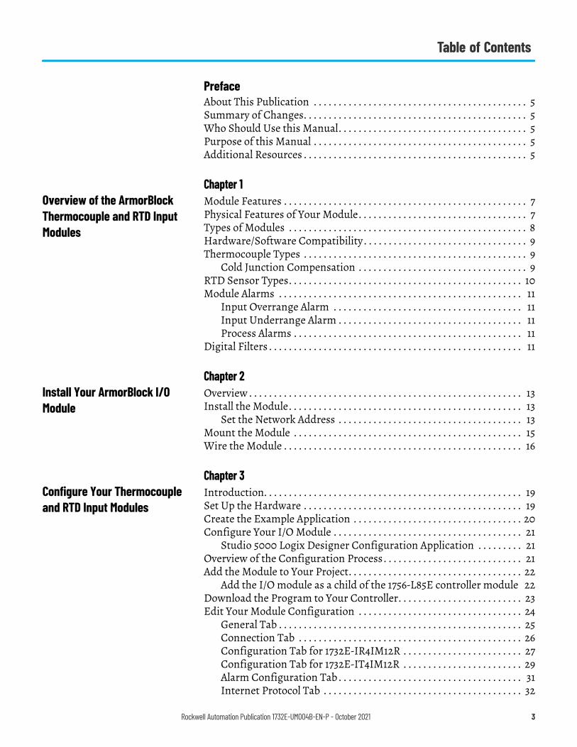
Table of Contents
PrefaceAbout This Publication . . . . . . . . . . . . . . . . . . . . . . . . . . . . . . . . . . . . . . . . . . . 5Summary of Changes. . . . . . . . . . . . . . . . . . . . . . . . . . . . . . . . . . . . . . . . . . . . . 5Who Should Use this Manual. . . . . . . . . . . . . . . . . . . . . . . . . . . . . . . . . . . . . . 5Purpose of this Manual . . . . . . . . . . . . . . . . . . . . . . . . . . . . . . . . . . . . . . . . . . . 5Additional Resources . . . . . . . . . . . . . . . . . . . . . . . . . . . . . . . . . . . . . . . . . . . . . 5
Chapter 1Overview of the ArmorBlock Thermocouple and RTD Input Modules
Module Features . . . . . . . . . . . . . . . . . . . . . . . . . . . . . . . . . . . . . . . . . . . . . . . . . 7Physical Features of Your Module. . . . . . . . . . . . . . . . . . . . . . . . . . . . . . . . . . 7Types of Modules . . . . . . . . . . . . . . . . . . . . . . . . . . . . . . . . . . . . . . . . . . . . . . . . 8Hardware/Software Compatibility . . . . . . . . . . . . . . . . . . . . . . . . . . . . . . . . . 9Thermocouple Types . . . . . . . . . . . . . . . . . . . . . . . . . . . . . . . . . . . . . . . . . . . . . 9
Cold Junction Compensation . . . . . . . . . . . . . . . . . . . . . . . . . . . . . . . . . . 9RTD Sensor Types. . . . . . . . . . . . . . . . . . . . . . . . . . . . . . . . . . . . . . . . . . . . . . . 10Module Alarms . . . . . . . . . . . . . . . . . . . . . . . . . . . . . . . . . . . . . . . . . . . . . . . . . 11
Input Overrange Alarm . . . . . . . . . . . . . . . . . . . . . . . . . . . . . . . . . . . . . . 11Input Underrange Alarm . . . . . . . . . . . . . . . . . . . . . . . . . . . . . . . . . . . . . 11Process Alarms . . . . . . . . . . . . . . . . . . . . . . . . . . . . . . . . . . . . . . . . . . . . . . 11
Digital Filters . . . . . . . . . . . . . . . . . . . . . . . . . . . . . . . . . . . . . . . . . . . . . . . . . . . 11
Chapter 2Install Your ArmorBlock I/O Module
Overview . . . . . . . . . . . . . . . . . . . . . . . . . . . . . . . . . . . . . . . . . . . . . . . . . . . . . . . 13Install the Module. . . . . . . . . . . . . . . . . . . . . . . . . . . . . . . . . . . . . . . . . . . . . . . 13
Set the Network Address . . . . . . . . . . . . . . . . . . . . . . . . . . . . . . . . . . . . . 13Mount the Module . . . . . . . . . . . . . . . . . . . . . . . . . . . . . . . . . . . . . . . . . . . . . . 15Wire the Module . . . . . . . . . . . . . . . . . . . . . . . . . . . . . . . . . . . . . . . . . . . . . . . . 16
Chapter 3Configure Your Thermocouple and RTD Input Modules
Introduction. . . . . . . . . . . . . . . . . . . . . . . . . . . . . . . . . . . . . . . . . . . . . . . . . . . . 19Set Up the Hardware . . . . . . . . . . . . . . . . . . . . . . . . . . . . . . . . . . . . . . . . . . . . 19Create the Example Application . . . . . . . . . . . . . . . . . . . . . . . . . . . . . . . . . . 20Configure Your I/O Module . . . . . . . . . . . . . . . . . . . . . . . . . . . . . . . . . . . . . . 21
Studio 5000 Logix Designer Configuration Application . . . . . . . . . 21Overview of the Configuration Process . . . . . . . . . . . . . . . . . . . . . . . . . . . . 21Add the Module to Your Project. . . . . . . . . . . . . . . . . . . . . . . . . . . . . . . . . . . 22
Add the I/O module as a child of the 1756-L85E controller module 22Download the Program to Your Controller. . . . . . . . . . . . . . . . . . . . . . . . . 23Edit Your Module Configuration . . . . . . . . . . . . . . . . . . . . . . . . . . . . . . . . . 24
General Tab . . . . . . . . . . . . . . . . . . . . . . . . . . . . . . . . . . . . . . . . . . . . . . . . . 25Connection Tab . . . . . . . . . . . . . . . . . . . . . . . . . . . . . . . . . . . . . . . . . . . . . 26Configuration Tab for 1732E-IR4IM12R . . . . . . . . . . . . . . . . . . . . . . . . 27Configuration Tab for 1732E-IT4IM12R . . . . . . . . . . . . . . . . . . . . . . . . 29Alarm Configuration Tab . . . . . . . . . . . . . . . . . . . . . . . . . . . . . . . . . . . . . 31Internet Protocol Tab . . . . . . . . . . . . . . . . . . . . . . . . . . . . . . . . . . . . . . . . 32
Rockwell Automation Publication 1732E-UM004B-EN-P - October 2021 3
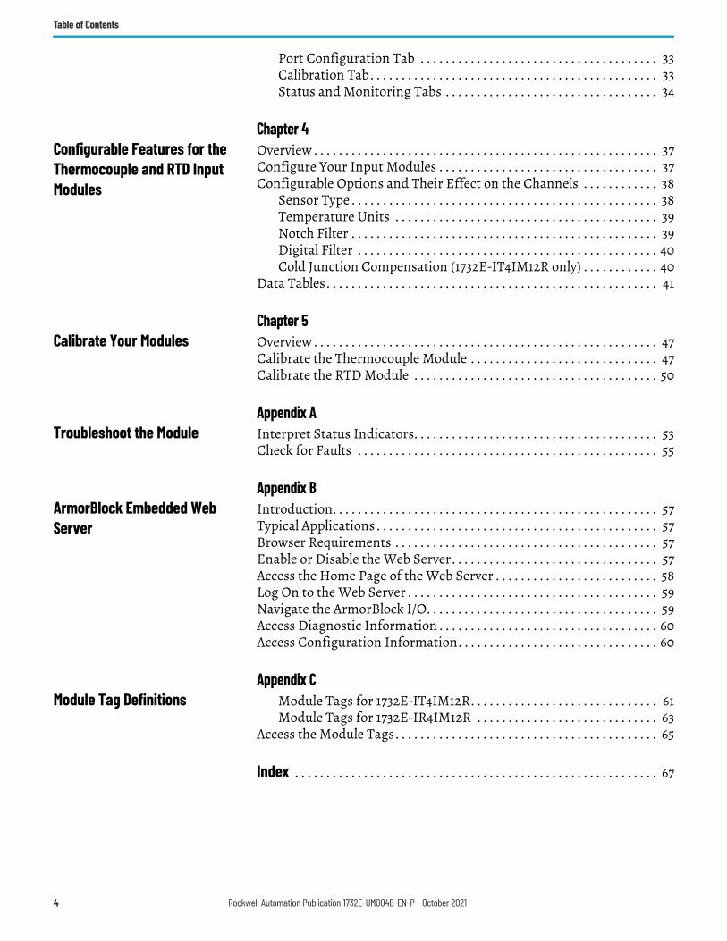
Table of Contents
Port Configuration Tab . . . . . . . . . . . . . . . . . . . . . . . . . . . . . . . . . . . . . . 33Calibration Tab. . . . . . . . . . . . . . . . . . . . . . . . . . . . . . . . . . . . . . . . . . . . . . 33Status and Monitoring Tabs . . . . . . . . . . . . . . . . . . . . . . . . . . . . . . . . . . 34
Chapter 4Configurable Features for the Thermocouple and RTD Input Modules
Overview . . . . . . . . . . . . . . . . . . . . . . . . . . . . . . . . . . . . . . . . . . . . . . . . . . . . . . . 37Configure Your Input Modules . . . . . . . . . . . . . . . . . . . . . . . . . . . . . . . . . . . 37Configurable Options and Their Effect on the Channels . . . . . . . . . . . . 38
Sensor Type . . . . . . . . . . . . . . . . . . . . . . . . . . . . . . . . . . . . . . . . . . . . . . . . . 38Temperature Units . . . . . . . . . . . . . . . . . . . . . . . . . . . . . . . . . . . . . . . . . . 39Notch Filter . . . . . . . . . . . . . . . . . . . . . . . . . . . . . . . . . . . . . . . . . . . . . . . . . 39Digital Filter . . . . . . . . . . . . . . . . . . . . . . . . . . . . . . . . . . . . . . . . . . . . . . . . 40Cold Junction Compensation (1732E-IT4IM12R only) . . . . . . . . . . . . 40
Data Tables. . . . . . . . . . . . . . . . . . . . . . . . . . . . . . . . . . . . . . . . . . . . . . . . . . . . . 41
Chapter 5Calibrate Your Modules Overview . . . . . . . . . . . . . . . . . . . . . . . . . . . . . . . . . . . . . . . . . . . . . . . . . . . . . . . 47
Calibrate the Thermocouple Module . . . . . . . . . . . . . . . . . . . . . . . . . . . . . . 47Calibrate the RTD Module . . . . . . . . . . . . . . . . . . . . . . . . . . . . . . . . . . . . . . . 50
Appendix ATroubleshoot the Module Interpret Status Indicators. . . . . . . . . . . . . . . . . . . . . . . . . . . . . . . . . . . . . . . 53
Check for Faults . . . . . . . . . . . . . . . . . . . . . . . . . . . . . . . . . . . . . . . . . . . . . . . . 55
Appendix BArmorBlock Embedded Web Server
Introduction. . . . . . . . . . . . . . . . . . . . . . . . . . . . . . . . . . . . . . . . . . . . . . . . . . . . 57Typical Applications . . . . . . . . . . . . . . . . . . . . . . . . . . . . . . . . . . . . . . . . . . . . . 57Browser Requirements . . . . . . . . . . . . . . . . . . . . . . . . . . . . . . . . . . . . . . . . . . 57Enable or Disable the Web Server. . . . . . . . . . . . . . . . . . . . . . . . . . . . . . . . . 57Access the Home Page of the Web Server . . . . . . . . . . . . . . . . . . . . . . . . . . 58Log On to the Web Server . . . . . . . . . . . . . . . . . . . . . . . . . . . . . . . . . . . . . . . . 59Navigate the ArmorBlock I/O. . . . . . . . . . . . . . . . . . . . . . . . . . . . . . . . . . . . . 59Access Diagnostic Information . . . . . . . . . . . . . . . . . . . . . . . . . . . . . . . . . . . 60Access Configuration Information. . . . . . . . . . . . . . . . . . . . . . . . . . . . . . . . 60
Appendix CModule Tag Definitions Module Tags for 1732E-IT4IM12R. . . . . . . . . . . . . . . . . . . . . . . . . . . . . . 61
Module Tags for 1732E-IR4IM12R . . . . . . . . . . . . . . . . . . . . . . . . . . . . . 63Access the Module Tags. . . . . . . . . . . . . . . . . . . . . . . . . . . . . . . . . . . . . . . . . . 65
Index . . . . . . . . . . . . . . . . . . . . . . . . . . . . . . . . . . . . . . . . . . . . . . . . . . . . . . . . . . 67
4 Rockwell Automation Publication 1732E-UM004B-EN-P - October 2021
Preface
About This Publication Read this preface to familiarize yourself with the rest of the manual. It provides information concerning:
• who should use this manual• the purpose of this manual• related documentation• conventions used in this manual
Summary of Changes This publication contains the following new or updated information. This list includes substantive updates only and is not intended to reflect all changes. Translated versions are not always available for each revision.
Who Should Use this Manual Use this manual if you are responsible for designing, installing, programming, or troubleshooting control systems that use ArmorBlock® EtherNet/IP™ Dual Port 4-Point Thermocouple and RTD Modules.
You should have a basic understanding of electrical circuitry and familiarity with relay logic. If you do not, obtain the proper training before using this product.
Purpose of this Manual This manual is a reference guide for the 1732E-IT4IM12R, 1732E-IR4IM12R modules. It describes the procedures you use to install, wire, troubleshoot, and use your module.
Additional Resources These documents contain additional information concerning related products from Rockwell Automation.
Topic PageReworded feature descriptions 7Improved descriptions of module features 8Added section Enable or Disable the Web Server 14Improved pinout and wiring description 17Improved description of input module configuration options 37Improved description of calibration overview 47Updated module status indicator description 54Corrected web server user name and password details 59Corrected configuration tag descriptions 61
Resource DescriptionPinout Guide for ArmorBlock I/O Dual Port EtherNet/IP Analog Modules 1732E-WD003
Information on wiring the ArmorBlock Dual-Port EtherNet/IP 4-Point Analog Modules (1732E-IF4M12R, 1732E-OF4M12R, 1732E-IT4IM12R, 1732E-IR4IM12R).
ArmorBlock Dual-port EtherNet/IP 4-point Thermocouple and RTD Input Modules Installation Instructions, publication 1732E-IN005 Information on installing the ArmorBlock EtherNet/IP module.
EtherNet/IP Device Level Ring Application Technique, publication ENET-AT007 A manual on how to install, configure and maintain linear and Device-level Ring (DLR) networks using Rockwell Automation EtherNet/IP devices with embedded switch technology.
EtherNet/IP Network Devices User Manual, ENET-UM006 Describes how to configure and use EtherNet/IP devices to communicate on the EtherNet/IP network.
Rockwell Automation Publication 1732E-UM004B-EN-P - October 2021 5
Preface
You can view or download publications at rok.auto/literature.
Ethernet Reference Manual, ENET-RM002 Describes basic Ethernet concepts, infrastructure components, and infrastructure features.
System Security Design Guidelines Reference Manual, SECURE-RM001Provides guidance on how to conduct security assessments, implement Rockwell Automation products in a secure system, harden the control system, manage user access, and dispose of equipment.
Industrial Components Preventive Maintenance, Enclosures, and Contact Ratings Specifications, publication IC-TD002
Provides a quick reference tool for Allen-Bradley® industrial automation controls and assemblies.
Safety Guidelines for the Application, Installation, and Maintenance of Solid-State Control, publication SGI-1.1
Designed to harmonize with NEMA Standards Publication No. ICS 1.1-1987 and provides general guidelines for the application, installation, and maintenance of solid-state control in the form of individual devices or packaged assemblies incorporating solid-state components.
Industrial Automation Wiring and Grounding Guidelines, publication 1770-4.1 Provides general guidelines for installing a Rockwell Automation industrial system.Product Certifications website, rok.auto/certifications. Provides declarations of conformity, certificates, and other certification details.
Resource Description
6 Rockwell Automation Publication 1732E-UM004B-EN-P - October 2021
Chapter 1
Overview of the ArmorBlock Thermocouple and RTD Input Modules
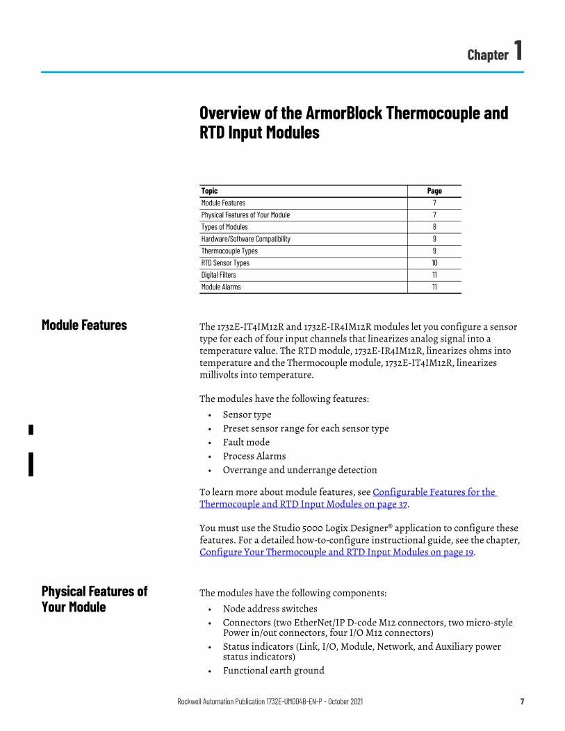
Module Features The 1732E-IT4IM12R and 1732E-IR4IM12R modules let you configure a sensor type for each of four input channels that linearizes analog signal into a temperature value. The RTD module, 1732E-IR4IM12R, linearizes ohms into temperature and the Thermocouple module, 1732E-IT4IM12R, linearizes millivolts into temperature.
The modules have the following features:• Sensor type• Preset sensor range for each sensor type• Fault mode• Process Alarms• Overrange and underrange detection
To learn more about module features, see Configurable Features for the Thermocouple and RTD Input Modules on page 37.
You must use the Studio 5000 Logix Designer® application to configure these features. For a detailed how-to-configure instructional guide, see the chapter, Configure Your Thermocouple and RTD Input Modules on page 19.
Physical Features of Your Module
The modules have the following components:
• Node address switches• Connectors (two EtherNet/IP D-code M12 connectors, two micro-style
Power in/out connectors, four I/O M12 connectors)• Status indicators (Link, I/O, Module, Network, and Auxiliary power
status indicators)• Functional earth ground
Topic PageModule Features 7Physical Features of Your Module 7Types of Modules 8Hardware/Software Compatibility 9Thermocouple Types 9RTD Sensor Types 10Digital Filters 11Module Alarms 11
Rockwell Automation Publication 1732E-UM004B-EN-P - October 2021 7
Chapter 1 Overview of the ArmorBlock Thermocouple and RTD Input Modules
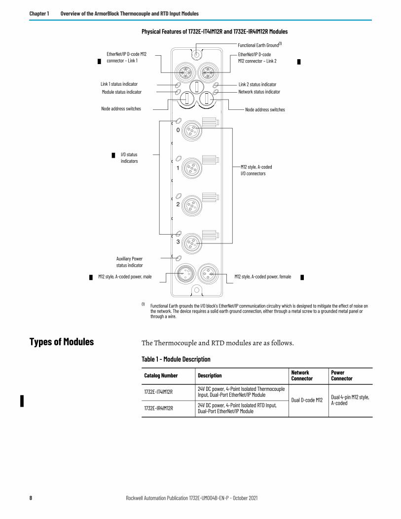
Physical Features of 1732E-IT4IM12R and 1732E-IR4IM12R Modules
(1) Functional Earth grounds the I/O block’s EtherNet/IP communication circuitry which is designed to mitigate the effect of noise on the network. The device requires a solid earth ground connection, either through a metal screw to a grounded metal panel or through a wire.
Types of Modules The Thermocouple and RTD modules are as follows.
Link 1 status indicator
EtherNet/IP D-code M12 connector – Link 2
Node address switches
M12 style, A-codedI/O connectors
M12 style, A-coded power, male
I/O status indicators
EtherNet/IP D-code M12 connector – Link 1
Link 2 status indicator
Node address switches
Network status indicatorModule status indicator
Auxiliary Power status indicator
Functional Earth Ground(1)
M12 style, A-coded power, female
Table 1 - Module Description
Catalog Number Description Network Connector
PowerConnector
1732E-IT4IM12R 24V DC power, 4-Point Isolated Thermocouple Input, Dual-Port EtherNet/IP Module
Dual D-code M12 Dual 4-pin M12 style, A-coded
1732E-IR4IM12R 24V DC power, 4-Point Isolated RTD Input, Dual-Port EtherNet/IP Module
8 Rockwell Automation Publication 1732E-UM004B-EN-P - October 2021
Chapter 1 Overview of the ArmorBlock Thermocouple and RTD Input Modules
Hardware/Software Compatibility
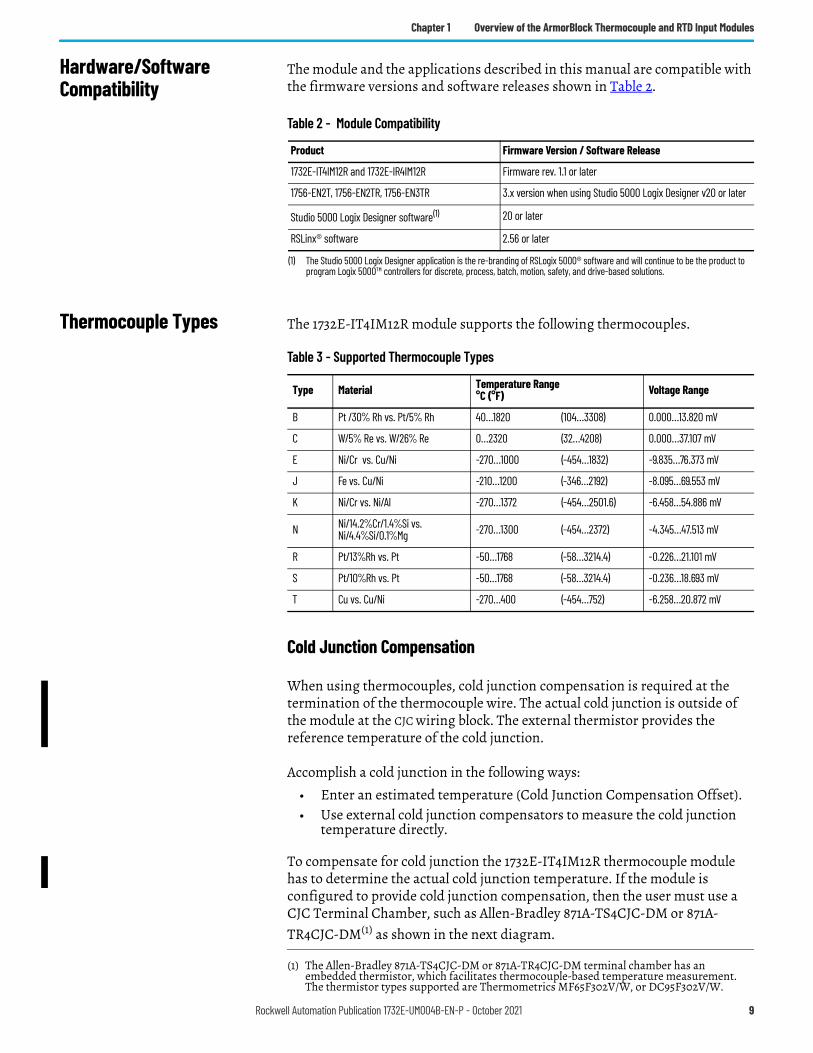
The module and the applications described in this manual are compatible with the firmware versions and software releases shown in Table 2.
Thermocouple Types The 1732E-IT4IM12R module supports the following thermocouples.
Cold Junction Compensation
When using thermocouples, cold junction compensation is required at the termination of the thermocouple wire. The actual cold junction is outside of the module at the CJC wiring block. The external thermistor provides the reference temperature of the cold junction.
Accomplish a cold junction in the following ways:• Enter an estimated temperature (Cold Junction Compensation Offset).• Use external cold junction compensators to measure the cold junction
temperature directly.
To compensate for cold junction the 1732E-IT4IM12R thermocouple module has to determine the actual cold junction temperature. If the module is configured to provide cold junction compensation, then the user must use a CJC Terminal Chamber, such as Allen-Bradley 871A-TS4CJC-DM or 871A-TR4CJC-DM(1) as shown in the next diagram.
Table 2 - Module Compatibility
Product Firmware Version / Software Release
1732E-IT4IM12R and 1732E-IR4IM12R Firmware rev. 1.1 or later
1756-EN2T, 1756-EN2TR, 1756-EN3TR 3.x version when using Studio 5000 Logix Designer v20 or later
Studio 5000 Logix Designer software(1)
(1) The Studio 5000 Logix Designer application is the re-branding of RSLogix 5000® software and will continue to be the product to program Logix 5000™ controllers for discrete, process, batch, motion, safety, and drive-based solutions.
20 or later
RSLinx® software 2.56 or later
Table 3 - Supported Thermocouple Types
Type Material Temperature Range°C (°F) Voltage Range
B Pt /30% Rh vs. Pt/5% Rh 40…1820 (104…3308) 0.000…13.820 mV
C W/5% Re vs. W/26% Re 0…2320 (32…4208) 0.000…37.107 mV
E Ni/Cr vs. Cu/Ni -270…1000 (-454…1832) -9.835…76.373 mV
J Fe vs. Cu/Ni -210…1200 (-346…2192) -8.095…69.553 mV
K Ni/Cr vs. Ni/Al -270…1372 (-454…2501.6) -6.458…54.886 mV
N Ni/14.2%Cr/1.4%Si vs. Ni/4.4%Si/0.1%Mg -270…1300 (-454…2372) -4.345…47.513 mV
R Pt/13%Rh vs. Pt -50…1768 (-58…3214.4) -0.226…21.101 mV
S Pt/10%Rh vs. Pt -50…1768 (-58…3214.4) -0.236…18.693 mV
T Cu vs. Cu/Ni -270…400 (-454…752) -6.258…20.872 mV
(1) The Allen-Bradley 871A-TS4CJC-DM or 871A-TR4CJC-DM terminal chamber has an embedded thermistor, which facilitates thermocouple-based temperature measurement. The thermistor types supported are Thermometrics MF65F302V/W, or DC95F302V/W.
Rockwell Automation Publication 1732E-UM004B-EN-P - October 2021 9
Chapter 1 Overview of the ArmorBlock Thermocouple and RTD Input Modules
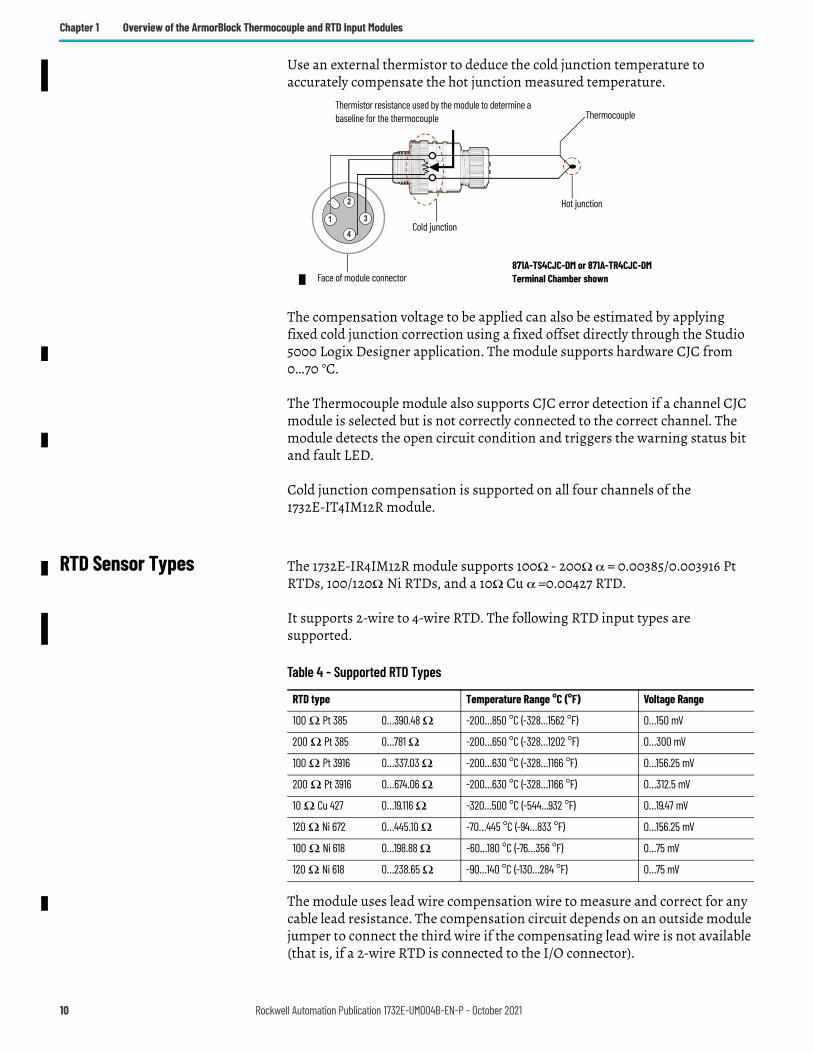
Use an external thermistor to deduce the cold junction temperature to accurately compensate the hot junction measured temperature.
The compensation voltage to be applied can also be estimated by applying fixed cold junction correction using a fixed offset directly through the Studio 5000 Logix Designer application. The module supports hardware CJC from 0…70 °C.
The Thermocouple module also supports CJC error detection if a channel CJC module is selected but is not correctly connected to the correct channel. The module detects the open circuit condition and triggers the warning status bit and fault LED.
Cold junction compensation is supported on all four channels of the 1732E-IT4IM12R module.
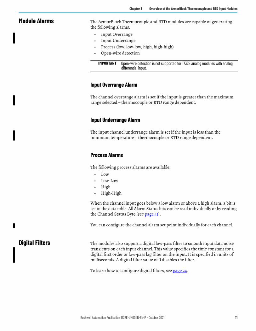
RTD Sensor Types The 1732E-IR4IM12R module supports 100Ω - 200Ω α = 0.00385/0.003916 Pt RTDs, 100/120Ω Ni RTDs, and a 10Ω Cu α =0.00427 RTD.
It supports 2-wire to 4-wire RTD. The following RTD input types are supported.
The module uses lead wire compensation wire to measure and correct for any cable lead resistance. The compensation circuit depends on an outside module jumper to connect the third wire if the compensating lead wire is not available (that is, if a 2-wire RTD is connected to the I/O connector).
3
41
2
Thermistor resistance used by the module to determine a baseline for the thermocouple Thermocouple
Hot junction
Cold junction
Face of module connector871A-TS4CJC-DM or 871A-TR4CJC-DM Terminal Chamber shown
Table 4 - Supported RTD Types
RTD type Temperature Range °C (°F) Voltage Range
100 Ω Pt 385 0…390.48 Ω -200…850 °C (-328…1562 °F) 0…150 mV
200 Ω Pt 385 0…781 Ω -200…650 °C (-328…1202 °F) 0…300 mV
100 Ω Pt 3916 0…337.03 Ω -200…630 °C (-328…1166 °F) 0…156.25 mV
200 Ω Pt 3916 0…674.06 Ω -200…630 °C (-328…1166 °F) 0…312.5 mV
10 Ω Cu 427 0…19.116 Ω -320…500 °C (-544…932 °F) 0…19.47 mV
120 Ω Ni 672 0…445.10 Ω -70…445 °C (-94…833 °F) 0…156.25 mV
100 Ω Ni 618 0…198.88 Ω -60…180 °C (-76…356 °F) 0…75 mV
120 Ω Ni 618 0…238.65 Ω -90…140 °C (-130…284 °F) 0…75 mV
10 Rockwell Automation Publication 1732E-UM004B-EN-P - October 2021
Chapter 1 Overview of the ArmorBlock Thermocouple and RTD Input Modules
Module Alarms The ArmorBlock Thermocouple and RTD modules are capable of generating the following alarms.
• Input Overrange• Input Underrange• Process (low, low-low, high, high-high)• Open-wire detection
Input Overrange Alarm
The channel overrange alarm is set if the input is greater than the maximum range selected – thermocouple or RTD range dependent.
Input Underrange Alarm
The input channel underrange alarm is set if the input is less than the minimum temperature – thermocouple or RTD range dependent.
Process Alarms
The following process alarms are available.• Low• Low-Low• High• High-High
When the channel input goes below a low alarm or above a high alarm, a bit is set in the data table. All Alarm Status bits can be read individually or by reading the Channel Status Byte (see page 41).
You can configure the channel alarm set point individually for each channel.
Digital Filters The modules also support a digital low-pass filter to smooth input data noise transients on each input channel. This value specifies the time constant for a digital first order or low-pass lag filter on the input. It is specified in units of milliseconds. A digital filter value of 0 disables the filter.
To learn how to configure digital filters, see page 24.
IMPORTANT Open-wire detection is not supported for 1732E analog modules with analog differential input.
Rockwell Automation Publication 1732E-UM004B-EN-P - October 2021 11
Chapter 1 Overview of the ArmorBlock Thermocouple and RTD Input Modules
Notes:
12 Rockwell Automation Publication 1732E-UM004B-EN-P - October 2021
Chapter 2
Install Your ArmorBlock I/O Module
Overview This chapter shows you how to install and wire the ArmorBlock EtherNet/IP Dual Port 4-Point Thermocouple and RTD Input modules. The only tools you require are a flat or Phillips head screwdriver and drill.
Install the Module To install the module:• Set the network address• Mount the module• Connect the I/O, Network, and Auxiliary cables to the module.
Set the Network Address
The I/O block ships with the rotary switches set to 999 and DHCP enabled. To change the network address, you can do one of the following:
• adjust the node address switches on the front of the module.• use a Dynamic Host Configuration Protocol (DHCP) server, such as
Rockwell Automation® BootP/DHCP.• retrieve the IP address from nonvolatile memory.
The I/O block reads the switches first to determine if the switches are set to a valid number. To set the network address:
1. Remove power.2. Remove the switch dust caps.3. Rotate the three (3) switches on the front of the module using a small
blade screwdriver.4. Line up the small notch on the switch with the number setting you wish
to use.Valid settings range from 001…254.
5. Replace switch dust caps. Make sure not to over tighten.6. Reapply power. 7. Record IP address on product label found on the side of enclosure.
Topic PageInstall the Module 13Set the Network Address 13Mount the Module 15Wire the Module 16
Rockwell Automation Publication 1732E-UM004B-EN-P - October 2021 13
Chapter 2 Install Your ArmorBlock I/O Module
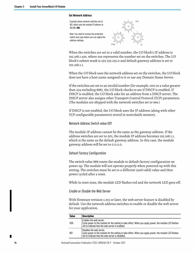
Set Network Address
When the switches are set to a valid number, the I/O block’s IP address is 192.168.1.xxx, where xxx represents the number set on the switches. The I/O block’s subnet mask is 255.255.255.0 and default gateway address is set to 192.168.1.1.
When the I/O block uses the network address set on the switches, the I/O block does not have a host name assigned to it or use any Domain Name Server.
If the switches are set to an invalid number (for example, 000 or a value greater than 254 excluding 888), the I/O block checks to see if DHCP is enabled. If DHCP is enabled, the I/O block asks for an address from a DHCP server. The DHCP server also assigns other Transport Control Protocol (TCP) parameters. (The modules are shipped with the network switches set to 999.)
If DHCP is not enabled, the I/O block uses the IP address (along with other TCP configurable parameters) stored in nonvolatile memory.
Network Address Switch value 001
The module IP address cannot be the same as the gateway address. If the address switches are set to 001, the module IP address becomes 192.168.1.1, which is the same as the default gateway address. In this case, the module gateway address will be set to 0.0.0.0.
Default Factory Configuration
The switch value 888 resets the module to default factory configuration on power up. The module will not operate properly when powered up with this setting. The switches must be set to a different (and valid) value and then power cycled after a reset.
While in reset state, the module LED flashes red and the network LED goes off.
Enable or Disable the Web Server
With firmware revision 1.013 or later, the web server feature is disabled by default. Use the network address switches to enable or disable the web server for your application.
Value Description
000Enables the web server.Cycle power to the module for the setting to take effect. When you apply power, the module LED flashes red to indicate that the web server is enabled.
901Disables the web server.Cycle power to the module for the setting to take effect. When you apply power, the module LED flashes red to indicate that the web server is disabled.
0
24
68
0
2
4
68
0
2
4
68
Note: You need to remove the protective switch dust caps before you can adjust the address settings.
Example shows network switches set at 163, which sets the module IP address to 192.168.1.163.
14 Rockwell Automation Publication 1732E-UM004B-EN-P - October 2021
Chapter 2 Install Your ArmorBlock I/O Module
For steps to enable or disable the web server, see Enable or Disable the Web Server on page 57.
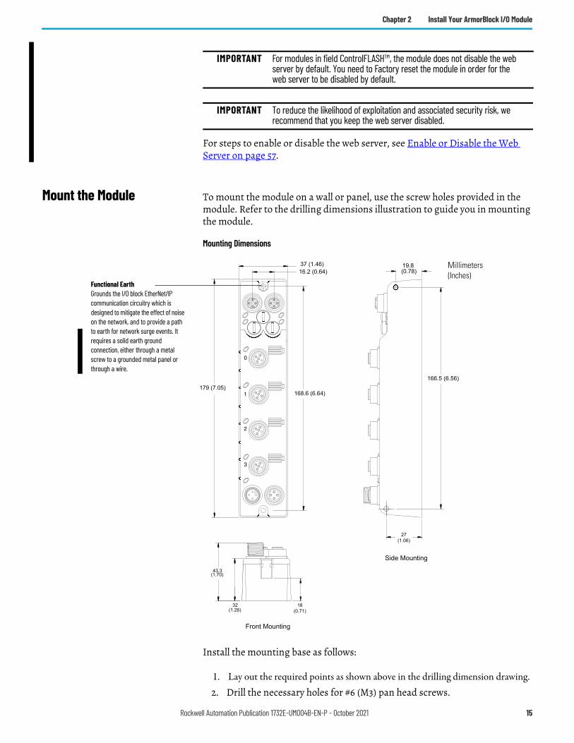
Mount the Module To mount the module on a wall or panel, use the screw holes provided in the module. Refer to the drilling dimensions illustration to guide you in mounting the module.
Mounting Dimensions
Install the mounting base as follows:
1. Lay out the required points as shown above in the drilling dimension drawing.2. Drill the necessary holes for #6 (M3) pan head screws.
IMPORTANT For modules in field ControlFLASH™, the module does not disable the web server by default. You need to Factory reset the module in order for the web server to be disabled by default.
IMPORTANT To reduce the likelihood of exploitation and associated security risk, we recommend that you keep the web server disabled.
37 (1.46)16.2 (0.64)
168.6 (6.64)
(1.26)32
(1.70)43.3
(0.78)19.8
166.5 (6.56)
27(1.06)
179 (7.05)
18(0.71)
Millimeters(Inches)
Functional EarthGrounds the I/O block EtherNet/IP communication circuitry which is designed to mitigate the effect of noise on the network, and to provide a path to earth for network surge events. It requires a solid earth ground connection, either through a metal screw to a grounded metal panel or through a wire.
Rockwell Automation Publication 1732E-UM004B-EN-P - October 2021 15
Chapter 2 Install Your ArmorBlock I/O Module
3. Mount the module using #6 (M3) screws.
Mount the Module in High Vibration Areas
If you mount the module in an area that is subject to shock or vibration, we recommend you use a flat and a lock washer to mount the module. Mount the flat and the lock washer as shown in the mounting illustration. Torque the mounting screws to 0.68 N•m (6 lb•in).
High Vibration Area Mounting
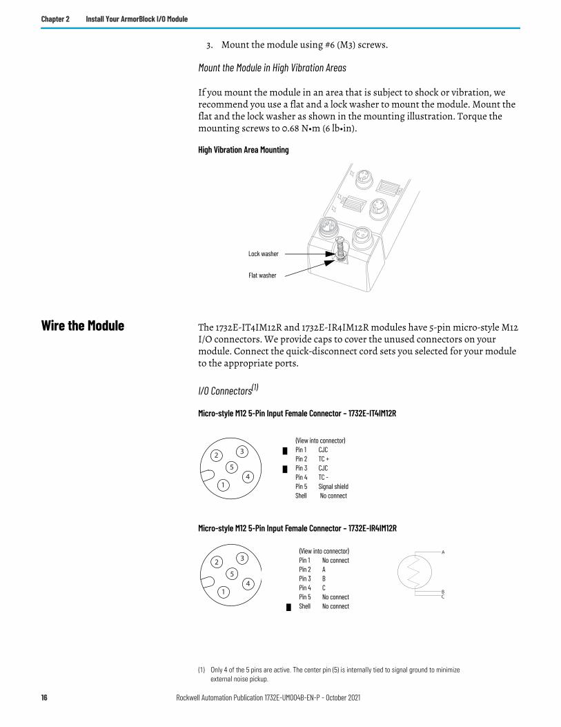
Wire the Module The 1732E-IT4IM12R and 1732E-IR4IM12R modules have 5-pin micro-style M12 I/O connectors. We provide caps to cover the unused connectors on your module. Connect the quick-disconnect cord sets you selected for your module to the appropriate ports.
I/O Connectors(1)
Micro-style M12 5-Pin Input Female Connector – 1732E-IT4IM12R
Micro-style M12 5-Pin Input Female Connector – 1732E-IR4IM12R
Lock washer
Flat washer
(1) Only 4 of the 5 pins are active. The center pin (5) is internally tied to signal ground to minimize external noise pickup.
3
41
2
5
(View into connector)Pin 1 CJCPin 2 TC +Pin 3 CJCPin 4 TC -Pin 5 Signal shieldShell No connect
A
CB
3
41
2
5
(View into connector)Pin 1 No connectPin 2 APin 3 BPin 4 CPin 5 No connectShell No connect
16 Rockwell Automation Publication 1732E-UM004B-EN-P - October 2021
Chapter 2 Install Your ArmorBlock I/O Module
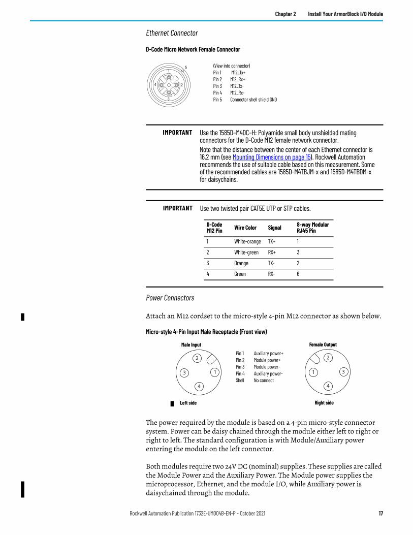
Ethernet Connector
D-Code Micro Network Female Connector
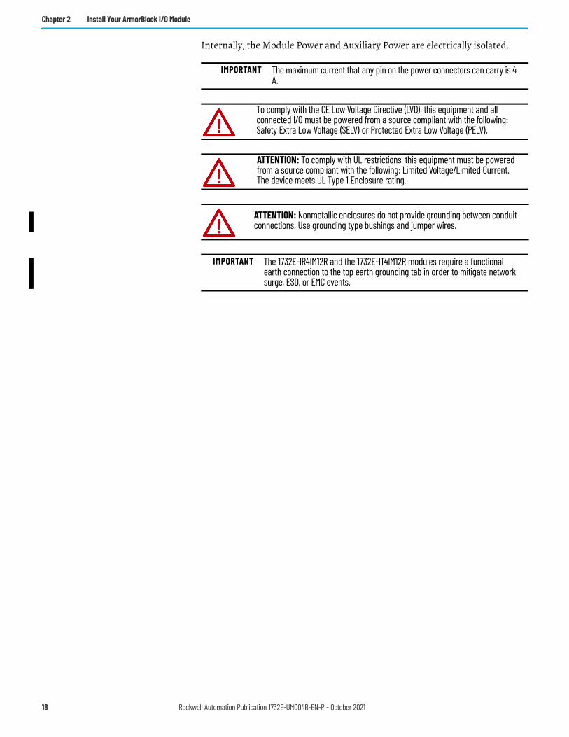
Power Connectors
Attach an M12 cordset to the micro-style 4-pin M12 connector as shown below.
Micro-style 4-Pin Input Male Receptacle (Front view)
The power required by the module is based on a 4-pin micro-style connector system. Power can be daisy chained through the module either left to right or right to left. The standard configuration is with Module/Auxiliary power entering the module on the left connector.
Both modules require two 24V DC (nominal) supplies. These supplies are called the Module Power and the Auxiliary Power. The Module power supplies the microprocessor, Ethernet, and the module I/O, while Auxiliary power is daisychained through the module.
IMPORTANT Use the 1585D–M4DC–H: Polyamide small body unshielded mating connectors for the D-Code M12 female network connector.Note that the distance between the center of each Ethernet connector is 16.2 mm (see Mounting Dimensions on page 15). Rockwell Automation recommends the use of suitable cable based on this measurement. Some of the recommended cables are 1585D-M4TBJM-x and 1585D-M4TBDM-x for daisychains.
IMPORTANT Use two twisted pair CAT5E UTP or STP cables.
4 2
3
15 (View into connector)
Pin 1 M12_Tx+Pin 2 M12_Rx+Pin 3 M12_Tx-Pin 4 M12_Rx-Pin 5 Connector shell shield GND
D-Code M12 Pin Wire Color Signal 8-way Modular
RJ45 Pin
1 White-orange TX+ 1
2 White-green RX+ 3
3 Orange TX- 2
4 Green RX- 6
1
4
3
2
Male Input Female Output
Pin 1 Auxiliary power+Pin 2 Module power+Pin 3 Module power-Pin 4 Auxiliary power-Shell No connect
3
4
1
2
Left side Right side
Rockwell Automation Publication 1732E-UM004B-EN-P - October 2021 17
Chapter 2 Install Your ArmorBlock I/O Module
Internally, the Module Power and Auxiliary Power are electrically isolated.
IMPORTANT The maximum current that any pin on the power connectors can carry is 4 A.
To comply with the CE Low Voltage Directive (LVD), this equipment and all connected I/O must be powered from a source compliant with the following: Safety Extra Low Voltage (SELV) or Protected Extra Low Voltage (PELV).
ATTENTION: To comply with UL restrictions, this equipment must be powered from a source compliant with the following: Limited Voltage/Limited Current.The device meets UL Type 1 Enclosure rating.
ATTENTION: Nonmetallic enclosures do not provide grounding between conduit connections. Use grounding type bushings and jumper wires.
IMPORTANT The 1732E-IR4IM12R and the 1732E-IT4IM12R modules require a functional earth connection to the top earth grounding tab in order to mitigate network surge, ESD, or EMC events.
18 Rockwell Automation Publication 1732E-UM004B-EN-P - October 2021
Chapter 3
Configure Your Thermocouple and RTD Input Modules
Introduction This chapter guides you through the steps required to configure your modules using the Studio 5000 Logix Designer application. Note that the modules presented in this chapter can be configured using the Studio 5000 Logix Designer application, version 20, or later.
Configuring the two modules using the Studio 5000 Logix Designer application involves the same general procedure. Note, however, that the two modules do not have exactly similar Module Definition properties. These are distinctly covered in this chapter.
Set Up the Hardware In this example, a ControlLogix® chassis contains the 1756-L85E processor in slot 1. The ArmorBlock module is mounted remotely.
Topic PageSet Up the Hardware 19Create the Example Application 20Configure Your I/O Module 21Overview of the Configuration Process 21Add the Module to Your Project 22Download the Program to Your Controller 23Edit Your Module Configuration 24
Rockwell Automation Publication 1732E-UM004B-EN-P - October 2021 19
Chapter 3 Configure Your Thermocouple and RTD Input Modules
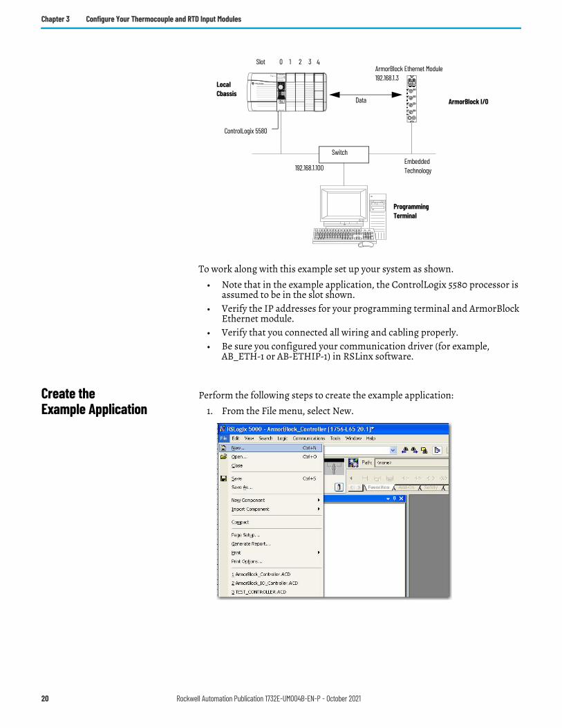
To work along with this example set up your system as shown.
• Note that in the example application, the ControlLogix 5580 processor is assumed to be in the slot shown.
• Verify the IP addresses for your programming terminal and ArmorBlock Ethernet module.
• Verify that you connected all wiring and cabling properly.• Be sure you configured your communication driver (for example,
AB_ETH-1 or AB-ETHIP-1) in RSLinx software.
Create the Example Application
Perform the following steps to create the example application:
1. From the File menu, select New.
LocalCbassis
ArmorBlock I/O
ControlLogix 5580
Data
Switch
192.168.1.100
Programming Terminal
0ArmorBlock Ethernet Module192.168.1.3
32Slot 1
Embedded Technology
4
20 Rockwell Automation Publication 1732E-UM004B-EN-P - October 2021
Chapter 3 Configure Your Thermocouple and RTD Input Modules
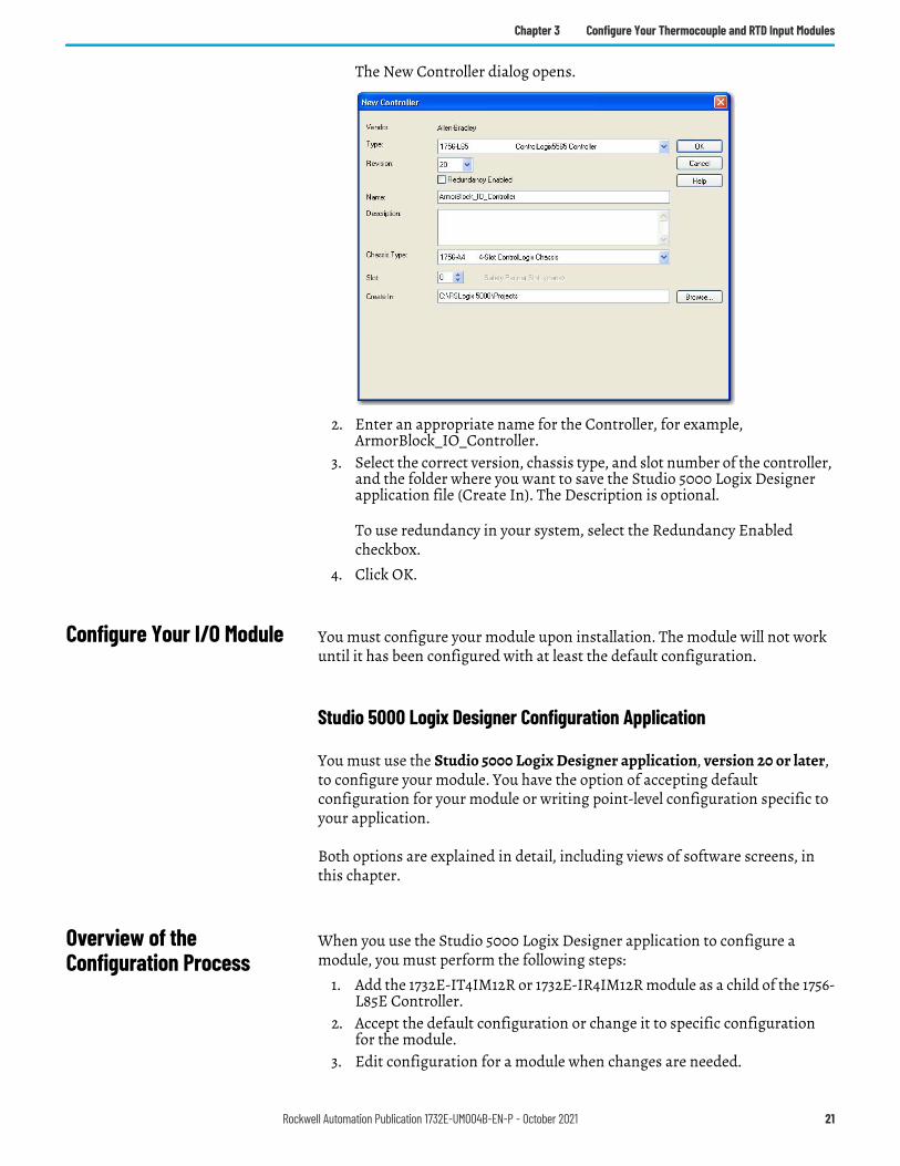
The New Controller dialog opens.
2. Enter an appropriate name for the Controller, for example, ArmorBlock_IO_Controller.
3. Select the correct version, chassis type, and slot number of the controller, and the folder where you want to save the Studio 5000 Logix Designer application file (Create In). The Description is optional.
To use redundancy in your system, select the Redundancy Enabled checkbox.
4. Click OK.
Configure Your I/O Module You must configure your module upon installation. The module will not work until it has been configured with at least the default configuration.
Studio 5000 Logix Designer Configuration Application
You must use the Studio 5000 Logix Designer application, version 20 or later, to configure your module. You have the option of accepting default configuration for your module or writing point-level configuration specific to your application.
Both options are explained in detail, including views of software screens, in this chapter.
Overview of the Configuration Process
When you use the Studio 5000 Logix Designer application to configure a module, you must perform the following steps:
1. Add the 1732E-IT4IM12R or 1732E-IR4IM12R module as a child of the 1756-L85E Controller.
2. Accept the default configuration or change it to specific configuration for the module.
3. Edit configuration for a module when changes are needed.
Rockwell Automation Publication 1732E-UM004B-EN-P - October 2021 21
Chapter 3 Configure Your Thermocouple and RTD Input Modules
Add the Module to Your Project
After you have started Studio 5000 Logix Designer application and created a controller, you must add a new module to your project.
The wizard allows you to create a new module and write configuration. You can use default configuration or write specific configuration for your application.
1. If necessary, go offline.
2. Add the EtherNet/IP Bridge to your project.
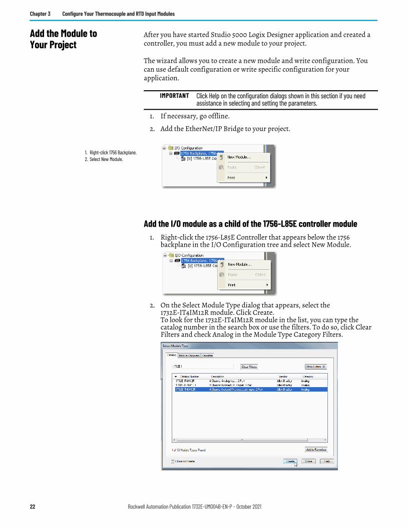
Add the I/O module as a child of the 1756-L85E controller module1. Right-click the 1756-L85E Controller that appears below the 1756
backplane in the I/O Configuration tree and select New Module.
2. On the Select Module Type dialog that appears, select the 1732E-IT4IM12R module. Click Create. To look for the 1732E-IT4IM12R module in the list, you can type the catalog number in the search box or use the filters. To do so, click Clear Filters and check Analog in the Module Type Category Filters.
IMPORTANT Click Help on the configuration dialogs shown in this section if you need assistance in selecting and setting the parameters.
1. Right-click 1756 Backplane.2. Select New Module.
22 Rockwell Automation Publication 1732E-UM004B-EN-P - October 2021
Chapter 3 Configure Your Thermocouple and RTD Input Modules
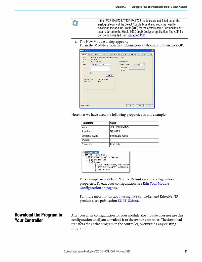
3. The New Module dialog appears.Fill in the Module Properties information as shown, and then click OK.
Note that we have used the following properties in this example:
To add the 1732E-IR4IM12R RTD module, follow the same steps. After adding the modules to your project, the I/O Configuration tree should appear as follows:
This example uses default Module Definition and configuration properties. To edit your configuration, see Edit Your Module Configuration on page 24.
For more information about using 1756 controller and EtherNet/IP products, see publication ENET-UM006.
Download the Program to Your Controller
After you write configuration for your module, the module does not use this configuration until you download it to the owner-controller. The download transfers the entire program to the controller, overwriting any existing program.
If the 1732E-IT4IM12R, 1732E-IR4IM12R modules are not listed under the analog category of the Select Module Type dialog you may need to download the Add-On Profile (AOP) for the ArmorBlock 2-Port and install it as an add-on to the Studio 5000 Logix Designer application. The AOP file can be downloaded from rok.auto/PCDC.
Field Name ValueName TEST_1732EIT4IM12RIP address 192.168.1.3Electronic keying Compatible ModuleRevision 1.1Connection Input Only
Rockwell Automation Publication 1732E-UM004B-EN-P - October 2021 23
Chapter 3 Configure Your Thermocouple and RTD Input Modules
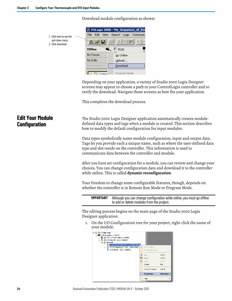
Download module configuration as shown:
Depending on your application, a variety of Studio 5000 Logix Designer screens may appear to choose a path to your ControlLogix controller and to verify the download. Navigate those screens as best fits your application.
This completes the download process.
Edit Your Module Configuration
The Studio 5000 Logix Designer application automatically creates module-defined data types and tags when a module is created. This section describes how to modify the default configuration for input modules.
Data types symbolically name module configuration, input and output data. Tags let you provide each a unique name, such as where the user-defined data type and slot reside on the controller. This information is used to communicate data between the controller and module.
After you have set configuration for a module, you can review and change your choices. You can change configuration data and download it to the controller while online. This is called dynamic reconfiguration.
Your freedom to change some configurable features, though, depends on whether the controller is in Remote Run Mode or Program Mode.
The editing process begins on the main page of the Studio 5000 Logix Designer application.
1. On the I/O Configuration tree for your project, right-click the name of your module.
1. Click here to see the pull-down menu.
2. Click download.
IMPORTANT Although you can change configuration while online, you must go offline to add or delete modules from the project.
24 Rockwell Automation Publication 1732E-UM004B-EN-P - October 2021
Chapter 3 Configure Your Thermocouple and RTD Input Modules
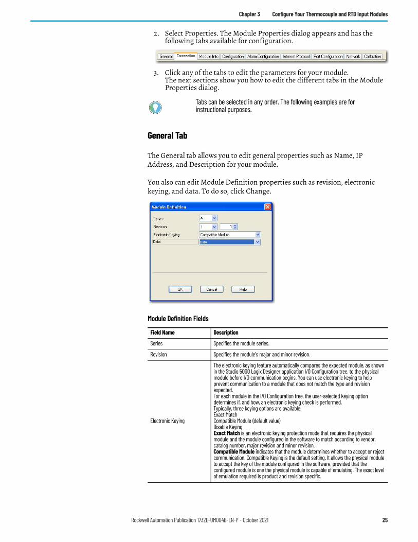
2. Select Properties. The Module Properties dialog appears and has the following tabs available for configuration.
3. Click any of the tabs to edit the parameters for your module. The next sections show you how to edit the different tabs in the Module Properties dialog.
General Tab
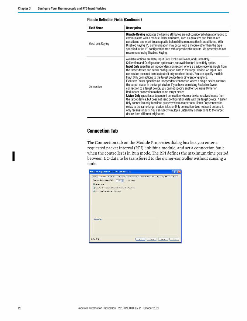
The General tab allows you to edit general properties such as Name, IP Address, and Description for your module.
You also can edit Module Definition properties such as revision, electronic keying, and data. To do so, click Change.
Tabs can be selected in any order. The following examples are for instructional purposes.
Module Definition Fields
Field Name Description
Series Specifies the module series.
Revision Specifies the module’s major and minor revision.
Electronic Keying
The electronic keying feature automatically compares the expected module, as shown in the Studio 5000 Logix Designer application I/O Configuration tree, to the physical module before I/O communication begins. You can use electronic keying to help prevent communication to a module that does not match the type and revision expected.For each module in the I/O Configuration tree, the user-selected keying option determines if, and how, an electronic keying check is performed.Typically, three keying options are available:Exact MatchCompatible Module (default value)Disable KeyingExact Match is an electronic keying protection mode that requires the physical module and the module configured in the software to match according to vendor, catalog number, major revision and minor revision.Compatible Module indicates that the module determines whether to accept or reject communication. Compatible Keying is the default setting. It allows the physical module to accept the key of the module configured in the software, provided that the configured module is one the physical module is capable of emulating. The exact level of emulation required is product and revision specific.
Rockwell Automation Publication 1732E-UM004B-EN-P - October 2021 25
Chapter 3 Configure Your Thermocouple and RTD Input Modules
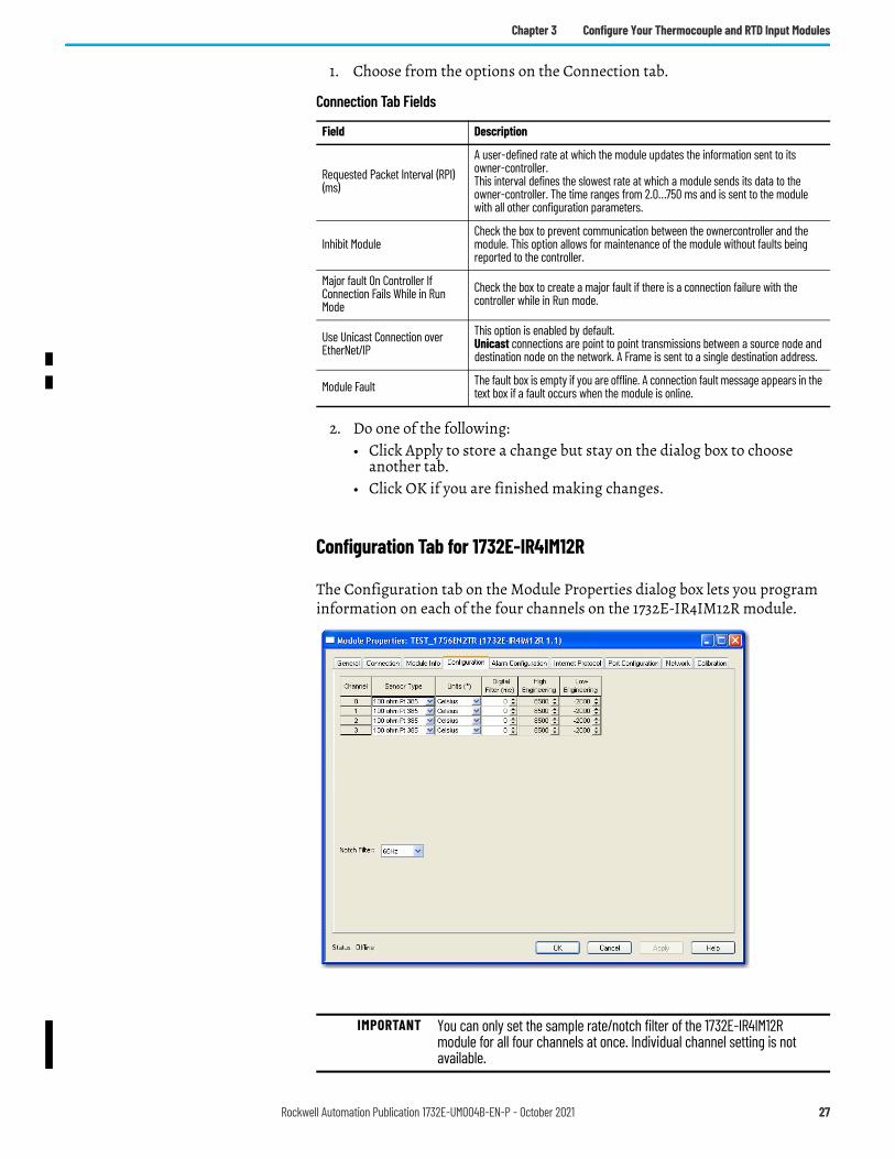
Connection Tab
The Connection tab on the Module Properties dialog box lets you enter a requested packet interval (RPI), inhibit a module, and set a connection fault when the controller is in Run mode. The RPI defines the maximum time period between I/O data to be transferred to the owner-controller without causing a fault.
Electronic Keying
Disable Keying indicates the keying attributes are not considered when attempting to communicate with a module. Other attributes, such as data size and format, are considered and must be acceptable before I/O communication is established. With Disabled Keying, I/O communication may occur with a module other than the type specified in the I/O configuration tree with unpredictable results. We generally do not recommend using Disabled Keying.
Connection
Available options are Data, Input Only, Exclusive Owner, and Listen Only.Calibration and Configuration options are not available for Listen Only option.Input Only specifies an independent connection where a device receives inputs from the target device and sends configuration data to the target device. An Input Only connection does not send outputs; it only receives inputs. You can specify multiple Input Only connections to the target device from different originators.Exclusive Owner specifies an independent connection where a single device controls the output states in the target device. If you have an existing Exclusive Owner connection to a target device, you cannot specify another Exclusive Owner or Redundant connection to that same target device.Listen Only specifies a dependent connection where a device receives inputs from the target device, but does not send configuration data with the target device. A Listen Only connection only functions properly when another non-Listen Only connection exists to the same target device. A Listen Only connection does not send outputs; it only receives inputs. You can specify multiple Listen Only connections to the target device from different originators.
Module Definition Fields (Continued)
Field Name Description
26 Rockwell Automation Publication 1732E-UM004B-EN-P - October 2021
Chapter 3 Configure Your Thermocouple and RTD Input Modules
1. Choose from the options on the Connection tab.
2. Do one of the following:• Click Apply to store a change but stay on the dialog box to choose
another tab.• Click OK if you are finished making changes.
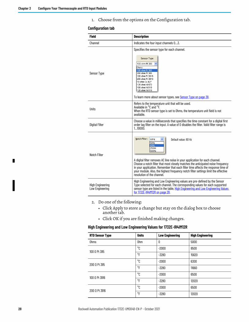
Configuration Tab for 1732E-IR4IM12R
The Configuration tab on the Module Properties dialog box lets you program information on each of the four channels on the 1732E-IR4IM12R module.
Connection Tab Fields
Field Description
Requested Packet Interval (RPI) (ms)
A user-defined rate at which the module updates the information sent to its owner-controller.This interval defines the slowest rate at which a module sends its data to the owner-controller. The time ranges from 2.0…750 ms and is sent to the module with all other configuration parameters.
Inhibit ModuleCheck the box to prevent communication between the ownercontroller and the module. This option allows for maintenance of the module without faults being reported to the controller.
Major fault On Controller If Connection Fails While in Run Mode
Check the box to create a major fault if there is a connection failure with the controller while in Run mode.
Use Unicast Connection over EtherNet/IP
This option is enabled by default.Unicast connections are point to point transmissions between a source node and destination node on the network. A Frame is sent to a single destination address.
Module Fault The fault box is empty if you are offline. A connection fault message appears in the text box if a fault occurs when the module is online.
IMPORTANT You can only set the sample rate/notch filter of the 1732E-IR4IM12R module for all four channels at once. Individual channel setting is not available.
Rockwell Automation Publication 1732E-UM004B-EN-P - October 2021 27
Chapter 3 Configure Your Thermocouple and RTD Input Modules
1. Choose from the options on the Configuration tab.
2. Do one of the following:• Click Apply to store a change but stay on the dialog box to choose
another tab.• Click OK if you are finished making changes.
Configuration tab
Field Description
Channel Indicates the four input channels 0…3.
Sensor Type
Specifies the sensor type for each channel.
To learn more about sensor types, see Sensor Type on page 38.
UnitsRefers to the temperature unit that will be used. Available in °C and °F. When the RTD sensor type is set to Ohms, the temperature unit field is not available.
Digital FilterChoose a value in milliseconds that specifies the time constant for a digital first order lag filter on the input. A value of 0 disables the filter. Valid filter range is 1…10000.
Notch FilterA digital filter removes AC line noise in your application for each channel.Choose a notch filter that most closely matches the anticipated noise frequency in your application. Remember that each filter time affects the response time of your module. Also, the highest frequency notch filter settings limit the effective resolution of the channel.
High EngineeringLow Engineering
High Engineering and Low Engineering values are pre-defined by the Sensor Type selected for each channel. The corresponding values for each supported sensor type are listed in the table, High Engineering and Low Engineering Values for 1732E-IR4IM12R on page 28.
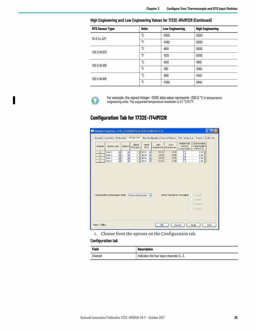
High Engineering and Low Engineering Values for 1732E-IR4IM12R
RTD Sensor Type Units Low Engineering High Engineering
Ohms Ohm 0 5000
100 Ω Pt 385°C -2000 8500
°F -3280 15620
200 Ω Pt 385°C -2000 6300
°F -3280 11660
100 Ω Pt 3916°C -2000 6500
°F -3280 12020
200 Ω Pt 3916°C -2000 6500
°F -3280 12020
Default value: 60 Hz
28 Rockwell Automation Publication 1732E-UM004B-EN-P - October 2021
Chapter 3 Configure Your Thermocouple and RTD Input Modules
Configuration Tab for 1732E-IT4IM12R
1. Choose from the options on the Configuration tab.
10 Ω Cu 427°C -1000 2600
°F -1480 5000
120 Ω Ni 672°C -800 2600
°F -1120 5000
100 Ω Ni 618°C -600 1800
°F -760 3560
120 Ω Ni 618°C -900 1400
°F -1300 2840
For example, the signed integer -2000 data value represents -200.0 °C in temperature engineering units. The supported temperature resolution is 0.1 °C/0.1°F.
High Engineering and Low Engineering Values for 1732E-IR4IM12R (Continued)
RTD Sensor Type Units Low Engineering High Engineering
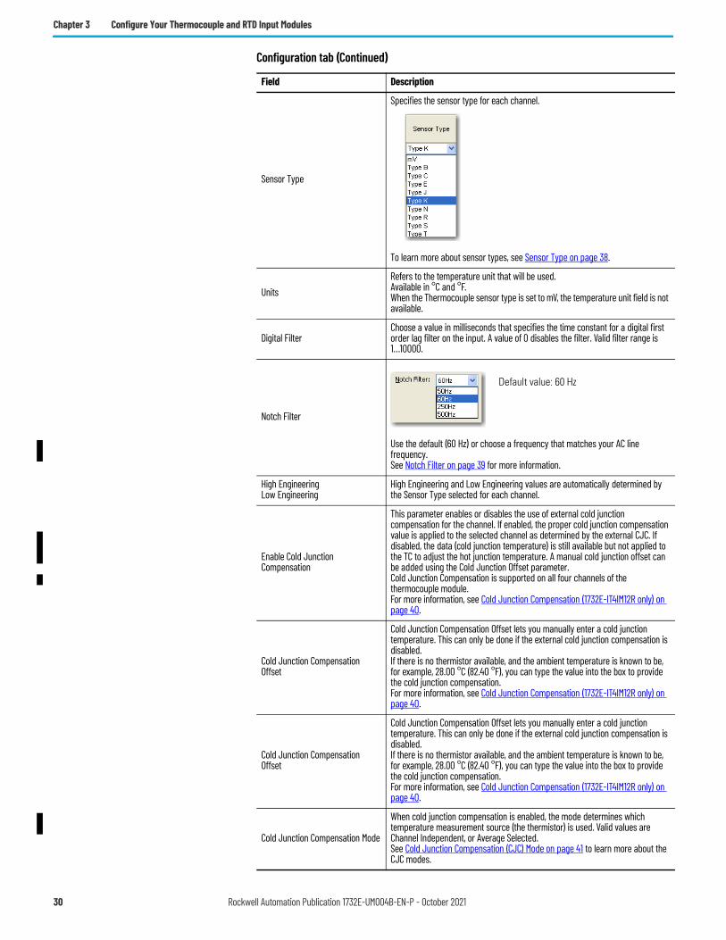
Configuration tab
Field Description
Channel Indicates the four input channels 0…3.
Rockwell Automation Publication 1732E-UM004B-EN-P - October 2021 29
Chapter 3 Configure Your Thermocouple and RTD Input Modules
Sensor Type
Specifies the sensor type for each channel.
To learn more about sensor types, see Sensor Type on page 38.
UnitsRefers to the temperature unit that will be used. Available in °C and °F. When the Thermocouple sensor type is set to mV, the temperature unit field is not available.
Digital FilterChoose a value in milliseconds that specifies the time constant for a digital first order lag filter on the input. A value of 0 disables the filter. Valid filter range is 1…10000.
Notch Filter
Use the default (60 Hz) or choose a frequency that matches your AC line frequency.See Notch Filter on page 39 for more information.
High EngineeringLow Engineering
High Engineering and Low Engineering values are automatically determined by the Sensor Type selected for each channel.
Enable Cold Junction Compensation
This parameter enables or disables the use of external cold junction compensation for the channel. If enabled, the proper cold junction compensation value is applied to the selected channel as determined by the external CJC. If disabled, the data (cold junction temperature) is still available but not applied to the TC to adjust the hot junction temperature. A manual cold junction offset can be added using the Cold Junction Offset parameter.Cold Junction Compensation is supported on all four channels of the thermocouple module.For more information, see Cold Junction Compensation (1732E-IT4IM12R only) on page 40.
Cold Junction Compensation Offset
Cold Junction Compensation Offset lets you manually enter a cold junction temperature. This can only be done if the external cold junction compensation is disabled.If there is no thermistor available, and the ambient temperature is known to be, for example, 28.00 °C (82.40 °F), you can type the value into the box to provide the cold junction compensation.For more information, see Cold Junction Compensation (1732E-IT4IM12R only) on page 40.
Cold Junction Compensation Mode
When cold junction compensation is enabled, the mode determines which temperature measurement source (the thermistor) is used. Valid values are Channel Independent, or Average Selected.See Cold Junction Compensation (CJC) Mode on page 41 to learn more about the CJC modes.
Configuration tab (Continued)
Field Description
Default value: 60 Hz
30 Rockwell Automation Publication 1732E-UM004B-EN-P - October 2021
Chapter 3 Configure Your Thermocouple and RTD Input Modules
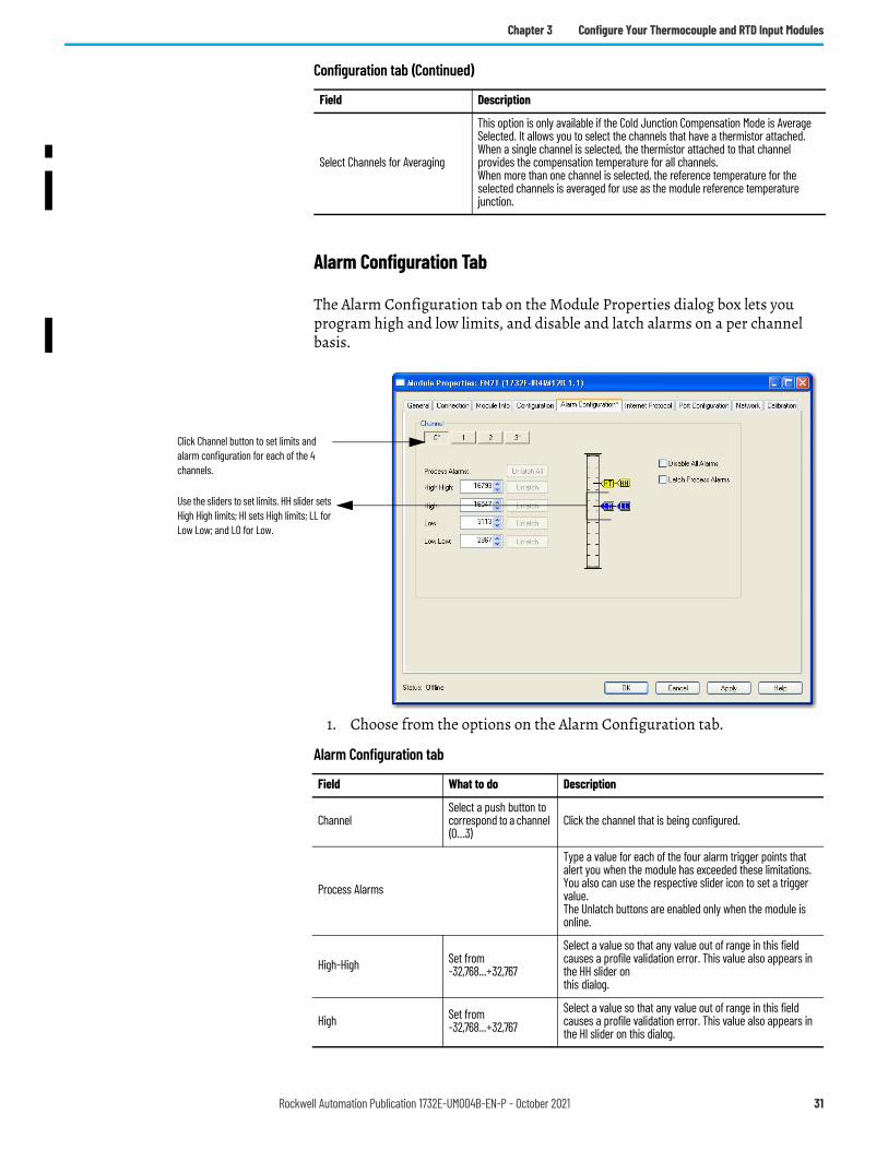
Alarm Configuration Tab
The Alarm Configuration tab on the Module Properties dialog box lets you program high and low limits, and disable and latch alarms on a per channel basis.
1. Choose from the options on the Alarm Configuration tab.
Select Channels for Averaging
This option is only available if the Cold Junction Compensation Mode is Average Selected. It allows you to select the channels that have a thermistor attached.When a single channel is selected, the thermistor attached to that channel provides the compensation temperature for all channels.When more than one channel is selected, the reference temperature for the selected channels is averaged for use as the module reference temperature junction.
Configuration tab (Continued)
Field Description
Click Channel button to set limits and alarm configuration for each of the 4 channels.
Use the sliders to set limits. HH slider sets High High limits; HI sets High limits; LL for Low Low; and LO for Low.
Alarm Configuration tab
Field What to do Description
ChannelSelect a push button to correspond to a channel (0…3)
Click the channel that is being configured.
Process Alarms
Type a value for each of the four alarm trigger points that alert you when the module has exceeded these limitations.You also can use the respective slider icon to set a trigger value.The Unlatch buttons are enabled only when the module is online.
High-High Set from-32,768...+32,767
Select a value so that any value out of range in this field causes a profile validation error. This value also appears in the HH slider onthis dialog.
High Set from-32,768...+32,767
Select a value so that any value out of range in this field causes a profile validation error. This value also appears in the HI slider on this dialog.
Rockwell Automation Publication 1732E-UM004B-EN-P - October 2021 31
Chapter 3 Configure Your Thermocouple and RTD Input Modules
2. After the channels are configured, do one of the following:• Click Apply to store a change but stay on the dialog box to choose
another tab.• Click OK to apply the change and close the dialog box.• Click Cancel to close the dialog box without applying changes.
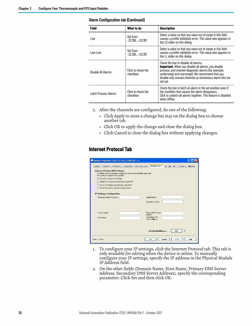
Internet Protocol Tab
1. To configure your IP settings, click the Internet Protocol tab. This tab is only available for editing when the device is online. To manually configure your IP settings, specify the IP address in the Physical Module IP Address field.
2. On the other fields (Domain Name, Host Name, Primary DNS Server Address, Secondary DNS Server Address), specify the corresponding parameter. Click Set and then click OK.
Low Set from-32,768...+32,767
Select a value so that any value out of range in this field causes a profile validation error. This value also appears in the LO slider on this dialog.
Low-Low Set from-32,768...+32,767
Select a value so that any value out of range in this field causes a profile validation error. This value also appears in the LL slider on this dialog.
Disable All Alarms Click to check the checkbox
Check the box to disable all alarms.Important: When you disable all alarms, you disable process, and channel diagnostic alarms (for example, underrange and overrange). We recommend that you disable only unused channels so extraneous alarm bits are not set.
Latch Process Alarms Click to check thecheckbox
Check the box to latch an alarm in the set position even if the condition that causes the alarm disappears. Click to unlatch all alarms together. This feature is disabled when offline
Alarm Configuration tab (Continued)
Field What to do Description
32 Rockwell Automation Publication 1732E-UM004B-EN-P - October 2021
Chapter 3 Configure Your Thermocouple and RTD Input Modules
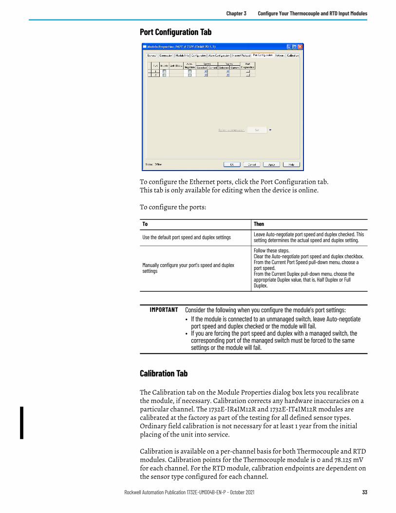
Port Configuration Tab
To configure the Ethernet ports, click the Port Configuration tab.This tab is only available for editing when the device is online.
To configure the ports:
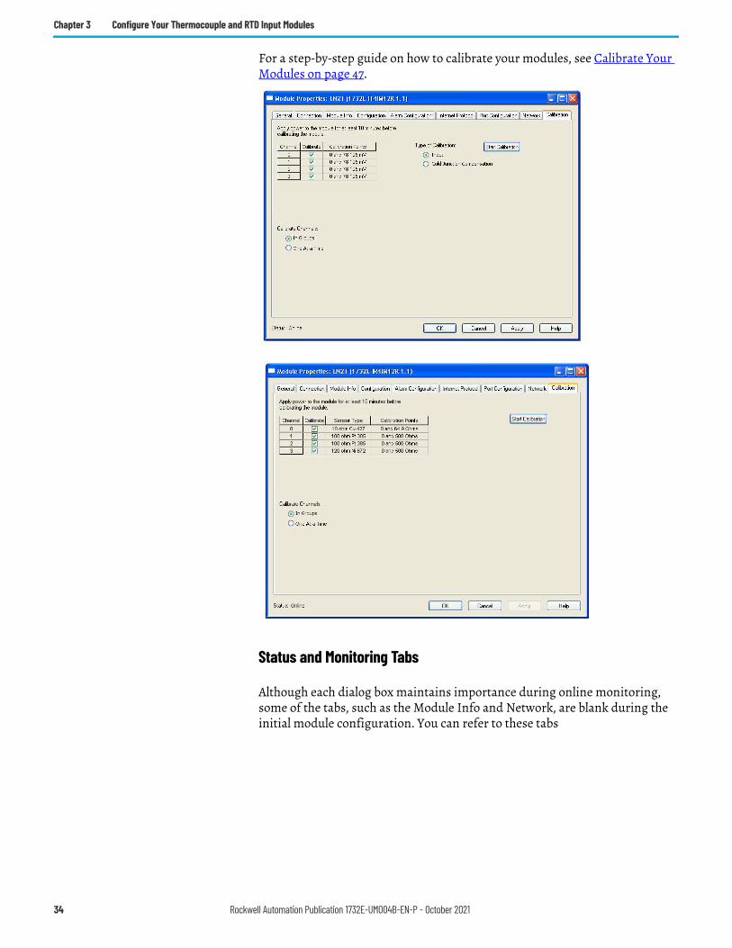
Calibration Tab
The Calibration tab on the Module Properties dialog box lets you recalibrate the module, if necessary. Calibration corrects any hardware inaccuracies on a particular channel. The 1732E-IR4IM12R and 1732E-IT4IM12R modules are calibrated at the factory as part of the testing for all defined sensor types. Ordinary field calibration is not necessary for at least 1 year from the initial placing of the unit into service.
Calibration is available on a per-channel basis for both Thermocouple and RTD modules. Calibration points for the Thermocouple module is 0 and 78.125 mV for each channel. For the RTD module, calibration endpoints are dependent on the sensor type configured for each channel.
To Then
Use the default port speed and duplex settings Leave Auto-negotiate port speed and duplex checked. This setting determines the actual speed and duplex setting.
Manually configure your port’s speed and duplex settings
Follow these steps.Clear the Auto-negotiate port speed and duplex checkbox.From the Current Port Speed pull-down menu, choose a port speed.From the Current Duplex pull-down menu, choose the appropriate Duplex value, that is, Half Duplex or Full Duplex.
IMPORTANT Consider the following when you configure the module’s port settings:• If the module is connected to an unmanaged switch, leave Auto-negotiate
port speed and duplex checked or the module will fail.• If you are forcing the port speed and duplex with a managed switch, the
corresponding port of the managed switch must be forced to the same settings or the module will fail.
Rockwell Automation Publication 1732E-UM004B-EN-P - October 2021 33
Chapter 3 Configure Your Thermocouple and RTD Input Modules
For a step-by-step guide on how to calibrate your modules, see Calibrate Your Modules on page 47.
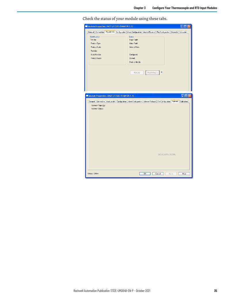
Status and Monitoring Tabs
Although each dialog box maintains importance during online monitoring, some of the tabs, such as the Module Info and Network, are blank during the initial module configuration. You can refer to these tabs
34 Rockwell Automation Publication 1732E-UM004B-EN-P - October 2021
Chapter 3 Configure Your Thermocouple and RTD Input Modules
Check the status of your module using these tabs.
Rockwell Automation Publication 1732E-UM004B-EN-P - October 2021 35

Chapter 3 Configure Your Thermocouple and RTD Input Modules
Notes:
36 Rockwell Automation Publication 1732E-UM004B-EN-P - October 2021
Chapter 4
Configurable Features for the Thermocouple and RTD Input Modules
Overview This chapter describes how the different configuration parameters affect the Thermocouple and RTD input channels. It also includes the data structure for both modules.
The parameters discussed in this chapter can be set through the Studio 5000 Logix Designer application. See the previous chapter, Configure Your Thermocouple and RTD Input Modules, to learn more about the step-by-step I/O configuration and setup process.
Configure Your Input Modules
The modules are configured using a group of data table words mapped by the processor that is used when the connection to the module is established.
The software configurable features available are:• sensor type• temperature units reported in °C, °F• cold junction compensation enable, mode, and offset
(for 1732E-IT4IM12R)• Sample Rate/Notch Filter• Digital Filter
Topic PageConfigure Your Input Modules 38Configurable Options and Their Effect on the Channels 38Data Tables 41
Rockwell Automation Publication 1732E-UM004B-EN-P - October 2021 37
Chapter 4 Configurable Features for the Thermocouple and RTD Input Modules
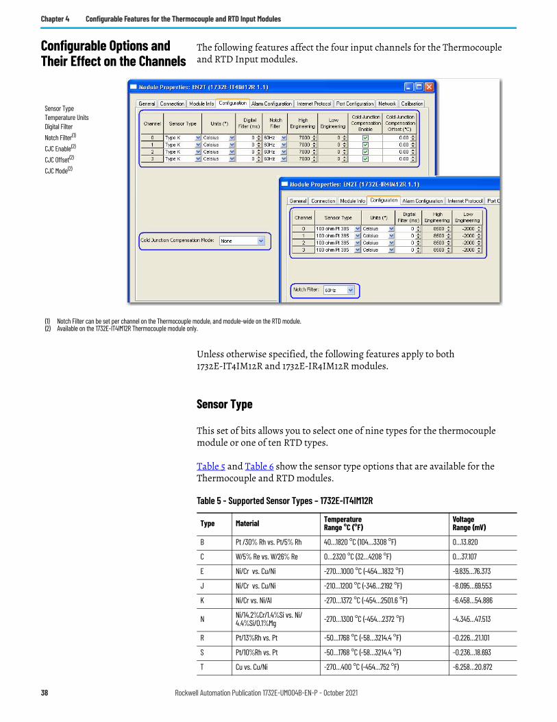
Configurable Options and Their Effect on the Channels
The following features affect the four input channels for the Thermocouple and RTD Input modules.
Unless otherwise specified, the following features apply to both 1732E-IT4IM12R and 1732E-IR4IM12R modules.
Sensor Type
This set of bits allows you to select one of nine types for the thermocouple module or one of ten RTD types.
Table 5 and Table 6 show the sensor type options that are available for the Thermocouple and RTD modules.
Sensor TypeTemperature UnitsDigital FilterNotch Filter(1)
CJC Enable(2)
CJC Offset(2)
CJC Mode(2)
(1) Notch Filter can be set per channel on the Thermocouple module, and module-wide on the RTD module.(2) Available on the 1732E-IT4IM12R Thermocouple module only.
Table 5 - Supported Sensor Types – 1732E-IT4IM12R
Type Material TemperatureRange °C (°F)
VoltageRange (mV)
B Pt /30% Rh vs. Pt/5% Rh 40…1820 °C (104…3308 °F) 0…13.820
C W/5% Re vs. W/26% Re 0…2320 °C (32…4208 °F) 0…37.107
E Ni/Cr vs. Cu/Ni -270…1000 °C (-454…1832 °F) -9.835…76.373
J Ni/Cr vs. Cu/Ni -210…1200 °C (-346…2192 °F) -8.095…69.553
K Ni/Cr vs. Ni/Al -270…1372 °C (-454…2501.6 °F) -6.458…54.886
N Ni/14.2%Cr/1.4%Si vs. Ni/4.4%Si/0.1%Mg -270…1300 °C (-454…2372 °F) -4.345…47.513
R Pt/13%Rh vs. Pt -50…1768 °C (-58…3214.4 °F) -0.226…21.101
S Pt/10%Rh vs. Pt -50…1768 °C (-58…3214.4 °F) -0.236…18.693
T Cu vs. Cu/Ni -270…400 °C (-454…752 °F) -6.258…20.872
38 Rockwell Automation Publication 1732E-UM004B-EN-P - October 2021
Chapter 4 Configurable Features for the Thermocouple and RTD Input Modules
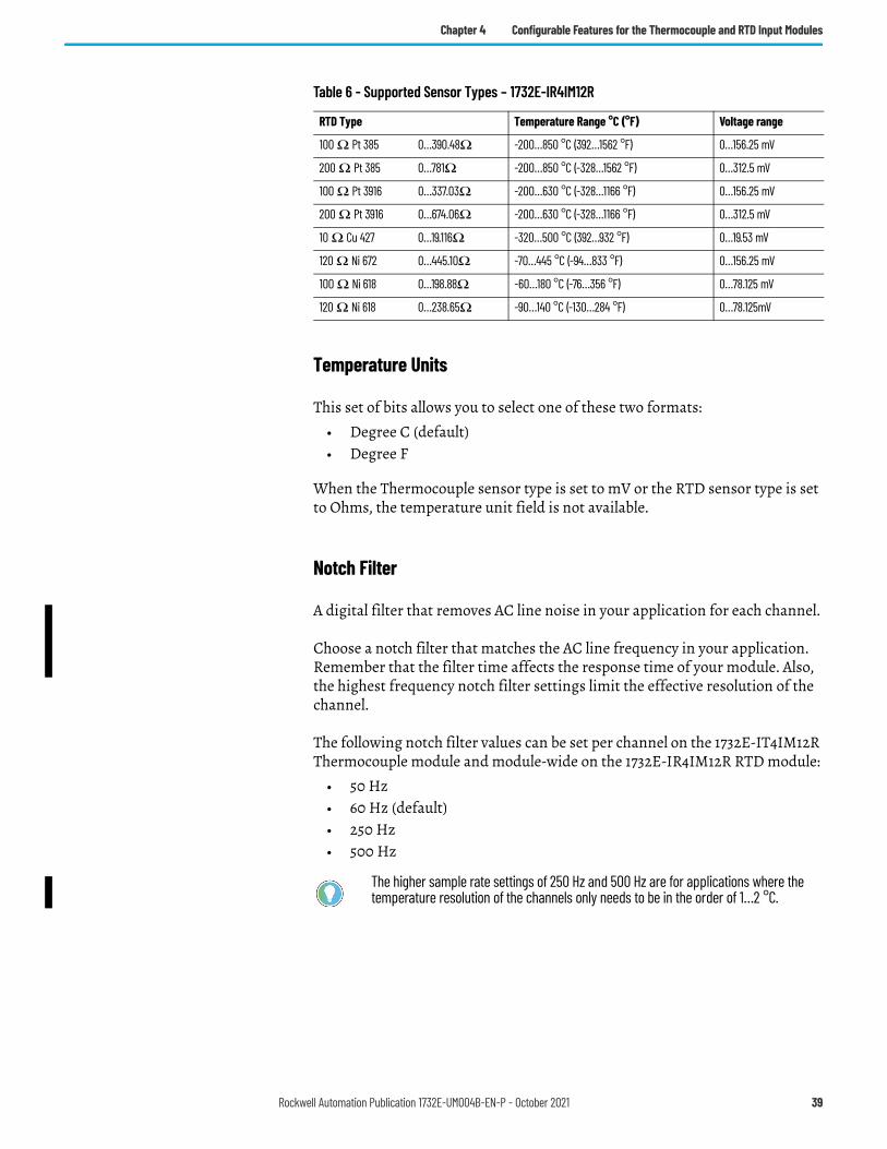
Temperature Units
This set of bits allows you to select one of these two formats:• Degree C (default)• Degree F
When the Thermocouple sensor type is set to mV or the RTD sensor type is set to Ohms, the temperature unit field is not available.
Notch Filter
A digital filter that removes AC line noise in your application for each channel.
Choose a notch filter that matches the AC line frequency in your application. Remember that the filter time affects the response time of your module. Also, the highest frequency notch filter settings limit the effective resolution of the channel.
The following notch filter values can be set per channel on the 1732E-IT4IM12R Thermocouple module and module-wide on the 1732E-IR4IM12R RTD module:
• 50 Hz• 60 Hz (default)• 250 Hz• 500 Hz
Table 6 - Supported Sensor Types – 1732E-IR4IM12R
RTD Type Temperature Range °C (°F) Voltage range
100 Ω Pt 385 0…390.48Ω -200…850 °C (392…1562 °F) 0…156.25 mV
200 Ω Pt 385 0…781Ω -200…850 °C (-328…1562 °F) 0…312.5 mV
100 Ω Pt 3916 0…337.03Ω -200…630 °C (-328…1166 °F) 0…156.25 mV
200 Ω Pt 3916 0…674.06Ω -200…630 °C (-328…1166 °F) 0…312.5 mV
10 Ω Cu 427 0…19.116Ω -320…500 °C (392…932 °F) 0…19.53 mV
120 Ω Ni 672 0…445.10Ω -70…445 °C (-94…833 °F) 0…156.25 mV
100 Ω Ni 618 0…198.88Ω -60…180 °C (-76…356 °F) 0…78.125 mV
120 Ω Ni 618 0…238.65Ω -90…140 °C (-130…284 °F) 0…78.125mV
The higher sample rate settings of 250 Hz and 500 Hz are for applications where the temperature resolution of the channels only needs to be in the order of 1…2 °C.
Rockwell Automation Publication 1732E-UM004B-EN-P - October 2021 39
Chapter 4 Configurable Features for the Thermocouple and RTD Input Modules
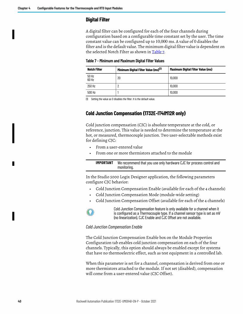
Digital Filter
A digital filter can be configured for each of the four channels during configuration based on a configurable time constant set by the user. The time constant value can be configured up to 10,000 ms. A value of 0 disables the filter and is the default value. The minimum digital filter value is dependent on the selected Notch Filter as shown in Table 7.
Cold Junction Compensation (1732E-IT4IM12R only)
Cold junction compensation (CJC) is absolute temperature at the cold, or reference, junction. This value is needed to determine the temperature at the hot, or measured, thermocouple junction. Two user-selectable methods exist for defining CJC:
• From a user-entered value• From one or more thermistors attached to the module
In the Studio 5000 Logix Designer application, the following parameters configure CJC behavior:
• Cold Junction Compensation Enable (available for each of the 4 channels)• Cold Junction Compensation Mode (module-wide setting)• Cold Junction Compensation Offset (available for each of the 4 channels)
Cold Junction Compensation Enable
The Cold Junction Compensation Enable box on the Module Properties Configuration tab enables cold junction compensation on each of the four channels. Typically, this option should always be enabled except for systems that have no thermoelectric effect, such as test equipment in a controlled lab.
When this parameter is set for a channel, compensation is derived from one or more thermistors attached to the module. If not set (disabled), compensation will come from a user-entered value (CJC Offset).
Table 7 - Minimum and Maximum Digital Filter Values
Notch Filter Minimum Digital Filter Value (ms)(1)
(1) Setting the value as 0 disables the filter. It is the default value.
Maximum Digital Filter Value (ms)
50 Hz60 Hz 20 10,000
250 Hz 2 10,000
500 Hz 1 10,000
IMPORTANT We recommend that you use only hardware CJC for process control and monitoring.
Cold Junction Compensation feature is only available for a channel when it is configured as a Thermocouple type. If a channel sensor type is set as mV (no linearization), CJC Enable and CJC Offset are not available.
40 Rockwell Automation Publication 1732E-UM004B-EN-P - October 2021
Chapter 4 Configurable Features for the Thermocouple and RTD Input Modules
In most applications, we recommend that you use the cold junction compensation enable option with the recommended thermistor based terminal blocks attached to the module.
Cold Junction Compensation (CJC) Mode
When CJC is enabled, CJC Mode determines which temperature channels are used for CJC calculations. The following options are available for the user:
• Average Selected• Channel Independent
When CJC Mode is Average Selected, all sensor channels will use an average of the compensation determined by thermistor(s) attached to the user-selected channel(s).
When CJC Mode is Channel Independent, each sensor channel uses the compensation derived from only the thermistor attached to the channel.
The produced cold junction compensation data is the temperature value read by the thermistor(s), in °C, which is being applied to the reading on any channel configured for thermistor compensation.
Cold Junction Compensation Offset
When no thermistor is attached to the module or channel, the user can specify the CJC Offset value to be added to the CJC input during temperature calculation. CJC Offset defines a reference temperature when no CJC thermistors are used. Valid values range from 0…70 °C, with 0 °C as default value.
CJC Offset parameter is enabled for configuration when the CJC Enable parameter is not checked for that channel.
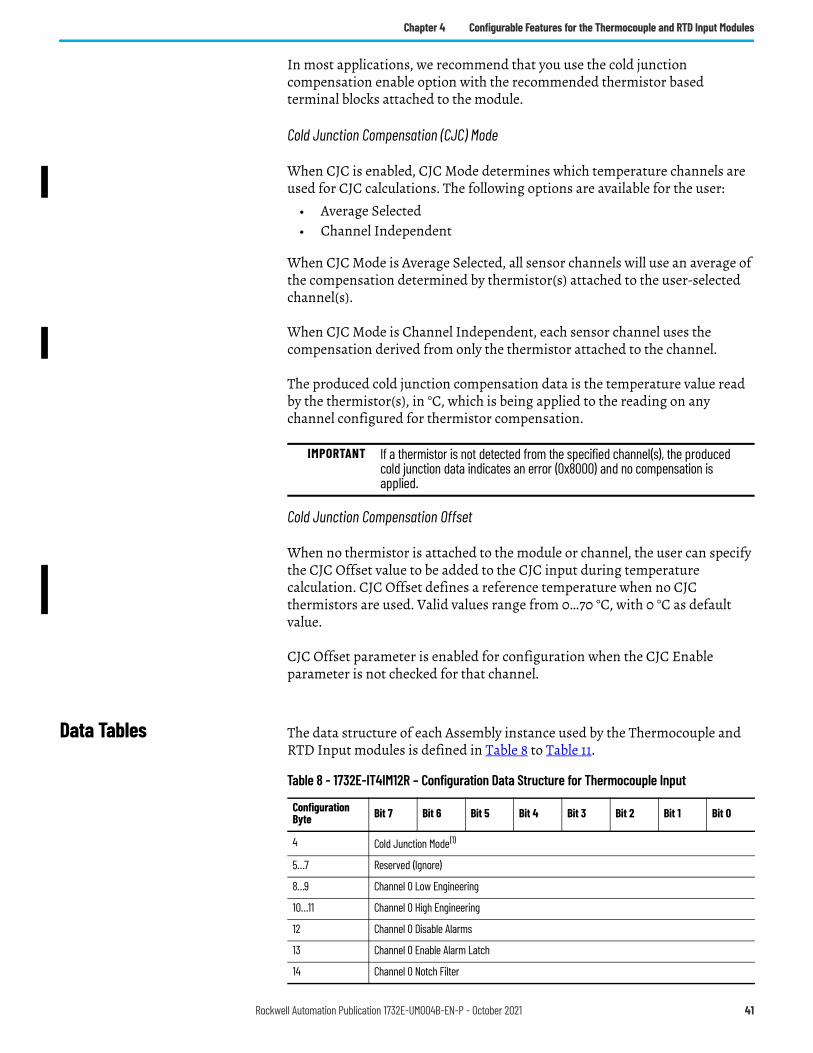
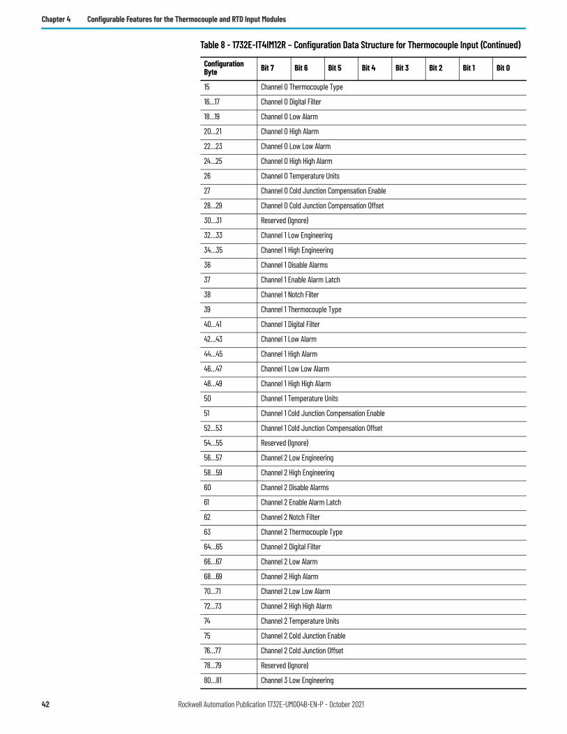
Data Tables The data structure of each Assembly instance used by the Thermocouple and RTD Input modules is defined in Table 8 to Table 11.
IMPORTANT If a thermistor is not detected from the specified channel(s), the produced cold junction data indicates an error (0x8000) and no compensation is applied.
Table 8 - 1732E-IT4IM12R – Configuration Data Structure for Thermocouple Input
Configuration Byte Bit 7 Bit 6 Bit 5 Bit 4 Bit 3 Bit 2 Bit 1 Bit 0
4 Cold Junction Mode(1)
5…7 Reserved (Ignore)
8…9 Channel 0 Low Engineering
10…11 Channel 0 High Engineering
12 Channel 0 Disable Alarms
13 Channel 0 Enable Alarm Latch
14 Channel 0 Notch Filter
Rockwell Automation Publication 1732E-UM004B-EN-P - October 2021 41
Chapter 4 Configurable Features for the Thermocouple and RTD Input Modules
15 Channel 0 Thermocouple Type
16…17 Channel 0 Digital Filter
18…19 Channel 0 Low Alarm
20…21 Channel 0 High Alarm
22…23 Channel 0 Low Low Alarm
24…25 Channel 0 High High Alarm
26 Channel 0 Temperature Units
27 Channel 0 Cold Junction Compensation Enable
28…29 Channel 0 Cold Junction Compensation Offset
30…31 Reserved (Ignore)
32…33 Channel 1 Low Engineering
34…35 Channel 1 High Engineering
36 Channel 1 Disable Alarms
37 Channel 1 Enable Alarm Latch
38 Channel 1 Notch Filter
39 Channel 1 Thermocouple Type
40…41 Channel 1 Digital Filter
42…43 Channel 1 Low Alarm
44…45 Channel 1 High Alarm
46…47 Channel 1 Low Low Alarm
48…49 Channel 1 High High Alarm
50 Channel 1 Temperature Units
51 Channel 1 Cold Junction Compensation Enable
52…53 Channel 1 Cold Junction Compensation Offset
54…55 Reserved (Ignore)
56…57 Channel 2 Low Engineering
58…59 Channel 2 High Engineering
60 Channel 2 Disable Alarms
61 Channel 2 Enable Alarm Latch
62 Channel 2 Notch Filter
63 Channel 2 Thermocouple Type
64…65 Channel 2 Digital Filter
66…67 Channel 2 Low Alarm
68…69 Channel 2 High Alarm
70…71 Channel 2 Low Low Alarm
72…73 Channel 2 High High Alarm
74 Channel 2 Temperature Units
75 Channel 2 Cold Junction Enable
76…77 Channel 2 Cold Junction Offset
78…79 Reserved (Ignore)
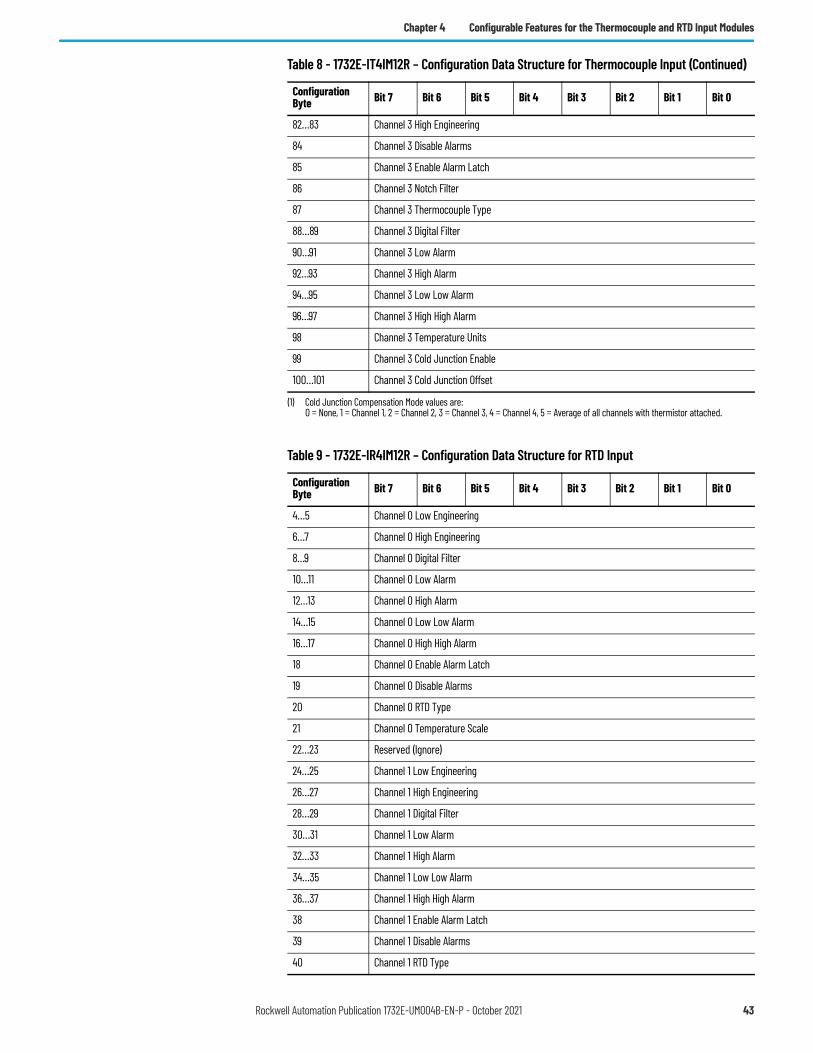
80…81 Channel 3 Low Engineering
Table 8 - 1732E-IT4IM12R – Configuration Data Structure for Thermocouple Input (Continued)
Configuration Byte Bit 7 Bit 6 Bit 5 Bit 4 Bit 3 Bit 2 Bit 1 Bit 0
42 Rockwell Automation Publication 1732E-UM004B-EN-P - October 2021
Chapter 4 Configurable Features for the Thermocouple and RTD Input Modules
82…83 Channel 3 High Engineering
84 Channel 3 Disable Alarms
85 Channel 3 Enable Alarm Latch
86 Channel 3 Notch Filter
87 Channel 3 Thermocouple Type
88…89 Channel 3 Digital Filter
90…91 Channel 3 Low Alarm
92…93 Channel 3 High Alarm
94…95 Channel 3 Low Low Alarm
96…97 Channel 3 High High Alarm
98 Channel 3 Temperature Units
99 Channel 3 Cold Junction Enable
100…101 Channel 3 Cold Junction Offset
(1) Cold Junction Compensation Mode values are:0 = None, 1 = Channel 1, 2 = Channel 2, 3 = Channel 3, 4 = Channel 4, 5 = Average of all channels with thermistor attached.
Table 9 - 1732E-IR4IM12R – Configuration Data Structure for RTD Input
Configuration Byte Bit 7 Bit 6 Bit 5 Bit 4 Bit 3 Bit 2 Bit 1 Bit 0
4…5 Channel 0 Low Engineering
6…7 Channel 0 High Engineering
8…9 Channel 0 Digital Filter
10…11 Channel 0 Low Alarm
12…13 Channel 0 High Alarm
14…15 Channel 0 Low Low Alarm
16…17 Channel 0 High High Alarm
18 Channel 0 Enable Alarm Latch
19 Channel 0 Disable Alarms
20 Channel 0 RTD Type
21 Channel 0 Temperature Scale
22…23 Reserved (Ignore)
24…25 Channel 1 Low Engineering
26…27 Channel 1 High Engineering
28…29 Channel 1 Digital Filter
30…31 Channel 1 Low Alarm
32…33 Channel 1 High Alarm
34…35 Channel 1 Low Low Alarm
36…37 Channel 1 High High Alarm
38 Channel 1 Enable Alarm Latch
39 Channel 1 Disable Alarms
40 Channel 1 RTD Type
Table 8 - 1732E-IT4IM12R – Configuration Data Structure for Thermocouple Input (Continued)
Configuration Byte Bit 7 Bit 6 Bit 5 Bit 4 Bit 3 Bit 2 Bit 1 Bit 0
Rockwell Automation Publication 1732E-UM004B-EN-P - October 2021 43
Chapter 4 Configurable Features for the Thermocouple and RTD Input Modules
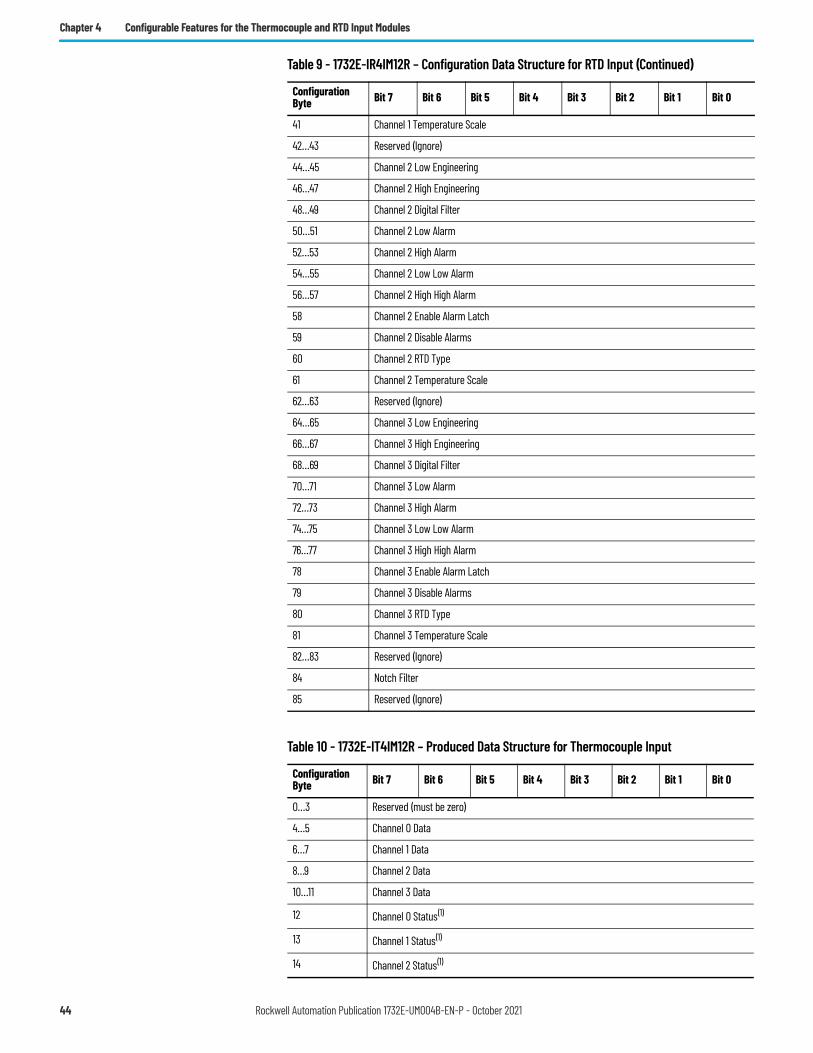
41 Channel 1 Temperature Scale
42…43 Reserved (Ignore)
44…45 Channel 2 Low Engineering
46…47 Channel 2 High Engineering
48…49 Channel 2 Digital Filter
50…51 Channel 2 Low Alarm
52…53 Channel 2 High Alarm
54…55 Channel 2 Low Low Alarm
56…57 Channel 2 High High Alarm
58 Channel 2 Enable Alarm Latch
59 Channel 2 Disable Alarms
60 Channel 2 RTD Type
61 Channel 2 Temperature Scale
62…63 Reserved (Ignore)
64…65 Channel 3 Low Engineering
66…67 Channel 3 High Engineering
68…69 Channel 3 Digital Filter
70…71 Channel 3 Low Alarm
72…73 Channel 3 High Alarm
74…75 Channel 3 Low Low Alarm
76…77 Channel 3 High High Alarm
78 Channel 3 Enable Alarm Latch
79 Channel 3 Disable Alarms
80 Channel 3 RTD Type
81 Channel 3 Temperature Scale
82…83 Reserved (Ignore)
84 Notch Filter
85 Reserved (Ignore)
Table 10 - 1732E-IT4IM12R – Produced Data Structure for Thermocouple Input
Configuration Byte Bit 7 Bit 6 Bit 5 Bit 4 Bit 3 Bit 2 Bit 1 Bit 0
0…3 Reserved (must be zero)
4…5 Channel 0 Data
6…7 Channel 1 Data
8…9 Channel 2 Data
10…11 Channel 3 Data
12 Channel 0 Status(1)
13 Channel 1 Status(1)
14 Channel 2 Status(1)
Table 9 - 1732E-IR4IM12R – Configuration Data Structure for RTD Input (Continued)
Configuration Byte Bit 7 Bit 6 Bit 5 Bit 4 Bit 3 Bit 2 Bit 1 Bit 0
44 Rockwell Automation Publication 1732E-UM004B-EN-P - October 2021
Chapter 4 Configurable Features for the Thermocouple and RTD Input Modules
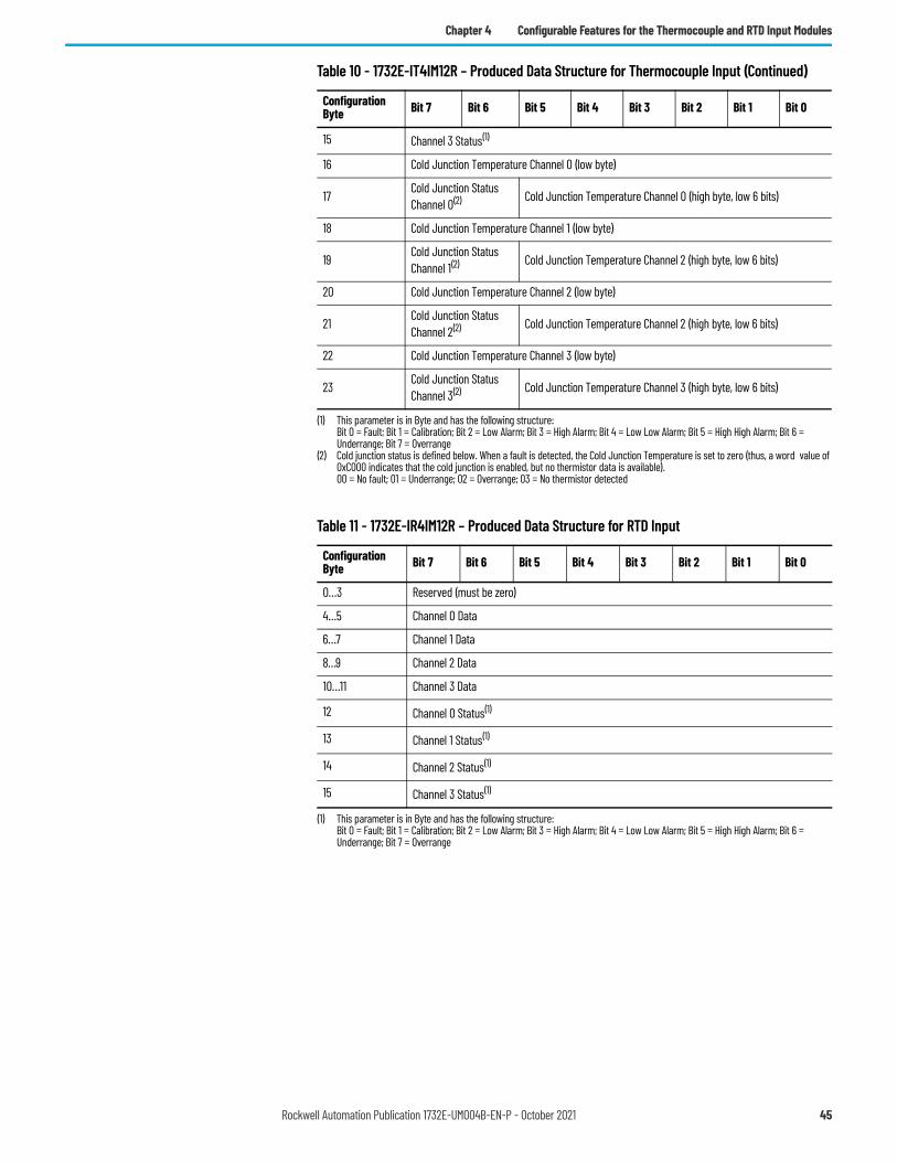
15 Channel 3 Status(1)
16 Cold Junction Temperature Channel 0 (low byte)
17 Cold Junction Status Channel 0(2) Cold Junction Temperature Channel 0 (high byte, low 6 bits)
18 Cold Junction Temperature Channel 1 (low byte)
19 Cold Junction Status Channel 1(2) Cold Junction Temperature Channel 2 (high byte, low 6 bits)
20 Cold Junction Temperature Channel 2 (low byte)
21 Cold Junction Status Channel 2(2) Cold Junction Temperature Channel 2 (high byte, low 6 bits)
22 Cold Junction Temperature Channel 3 (low byte)
23 Cold Junction Status Channel 3(2) Cold Junction Temperature Channel 3 (high byte, low 6 bits)
(1) This parameter is in Byte and has the following structure:Bit 0 = Fault; Bit 1 = Calibration; Bit 2 = Low Alarm; Bit 3 = High Alarm; Bit 4 = Low Low Alarm; Bit 5 = High High Alarm; Bit 6 = Underrange; Bit 7 = Overrange
(2) Cold junction status is defined below. When a fault is detected, the Cold Junction Temperature is set to zero (thus, a word value of 0xC000 indicates that the cold junction is enabled, but no thermistor data is available).00 = No fault; 01 = Underrange; 02 = Overrange; 03 = No thermistor detected
Table 11 - 1732E-IR4IM12R – Produced Data Structure for RTD Input
Configuration Byte Bit 7 Bit 6 Bit 5 Bit 4 Bit 3 Bit 2 Bit 1 Bit 0
0…3 Reserved (must be zero)
4…5 Channel 0 Data
6…7 Channel 1 Data
8…9 Channel 2 Data
10…11 Channel 3 Data
12 Channel 0 Status(1)
(1) This parameter is in Byte and has the following structure:Bit 0 = Fault; Bit 1 = Calibration; Bit 2 = Low Alarm; Bit 3 = High Alarm; Bit 4 = Low Low Alarm; Bit 5 = High High Alarm; Bit 6 = Underrange; Bit 7 = Overrange
13 Channel 1 Status(1)
14 Channel 2 Status(1)
15 Channel 3 Status(1)
Table 10 - 1732E-IT4IM12R – Produced Data Structure for Thermocouple Input (Continued)
Configuration Byte Bit 7 Bit 6 Bit 5 Bit 4 Bit 3 Bit 2 Bit 1 Bit 0
Rockwell Automation Publication 1732E-UM004B-EN-P - October 2021 45

Chapter 4 Configurable Features for the Thermocouple and RTD Input Modules
Notes:
46 Rockwell Automation Publication 1732E-UM004B-EN-P - October 2021
Chapter 5
Calibrate Your Modules
Overview The Thermocouple and RTD modules are shipped to you calibrated but calibration is also made available through the Studio 5000 Logix Designer application should you choose to recalibrate your module to increase accuracy for your specific application. Calibration can only be adjusted to within 0.5% of the original factory calibration.
This chapter shows you how to calibrate your modules through the Studio 5000 Logix Designer application.
To maintain your module’s accuracy specifications, we recommend you use calibration instruments with specific ranges. The table lists the recommended instruments for the two modules.
Calibrate the Thermocouple Module
The 1732E-IT4IM12R module only calibrates in millivolts. You can calibrate the module to a 0…78.125 mV range.
Topic PageCalibrate the Thermocouple Module 47Calibrate the RTD Module 50
IMPORTANT Analog I/O modules can be calibrated on a channel-by-channel basis or with the channels grouped together. Regardless of which option you choose, we recommend you calibrate all channels on your module each time you calibrate. This will help you maintain consistent calibration readings and improve module accuracy.Calibration is meant to correct any hardware inaccuracies that may be present on a particular channel. The calibration procedure compares a known standard, either input signal or recorded output, with the channel’s performance and then calculating a linear correction factor between the measured and the ideal.The linear calibration correction factor is applied on every input or output same to obtain maximum accuracy.
Module Recommended Instrument Range
1732E-IT4IM12R 0 mV…78.125 mV source ±0.3 μV
1732E-IR4IM12R 0…1000 Ω resistors(1) ±0.01%
(1) We suggest you use these precision resistors. A precision decade resistor box also can be used that meets or exceeds the required accuracy specifications. You are responsible for assuring that the decade box maintains accuracy by periodic calibration.
Rockwell Automation Publication 1732E-UM004B-EN-P - October 2021 47
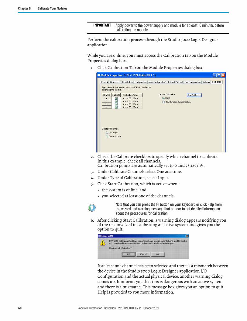
Chapter 5 Calibrate Your Modules
Perform the calibration process through the Studio 5000 Logix Designer application.
While you are online, you must access the Calibration tab on the Module Properties dialog box.
1. Click Calibration Tab on the Module Properties dialog box.
2. Check the Calibrate checkbox to specify which channel to calibrate. In this example, check all channels.Calibration points are automatically set to 0 and 78.125 mV.
3. Under Calibrate Channels select One at a time.4. Under Type of Calibration, select Input.5. Click Start Calibration, which is active when:
• the system is online, and• you selected at least one of the channels.
6. After clicking Start Calibration, a warning dialog appears notifying you of the risk involved in calibrating an active system and gives you the option to quit.
If at least one channel has been selected and there is a mismatch between the device in the Studio 5000 Logix Designer application I/O Configuration and the actual physical device, another warning dialog comes up. It informs you that this is dangerous with an active system and there is a mismatch. This message box gives you an option to quit. Help is provided to you more information.
IMPORTANT Apply power to the power supply and module for at least 10 minutes before calibrating the module.
Note that you can press the F1 button on your keyboard or click Help from the wizard and warning message that appear to get detailed information about the procedures for calibration.
48 Rockwell Automation Publication 1732E-UM004B-EN-P - October 2021
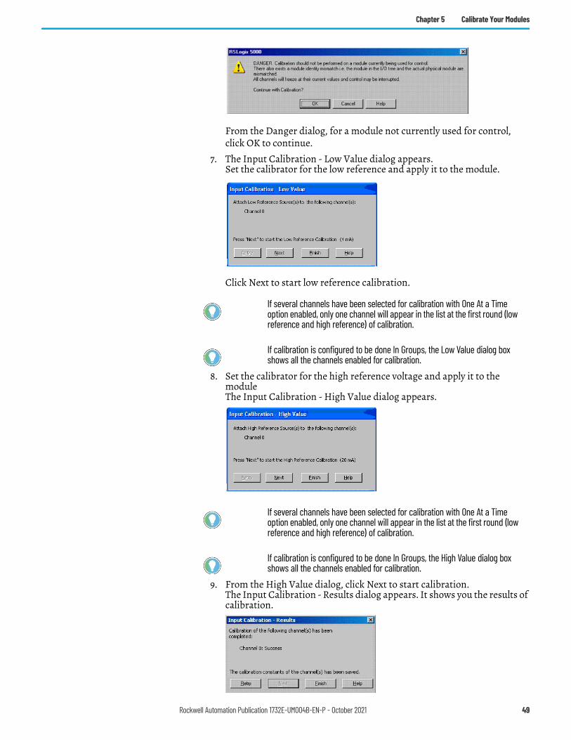
Chapter 5 Calibrate Your Modules
From the Danger dialog, for a module not currently used for control, click OK to continue.
7. The Input Calibration - Low Value dialog appears.Set the calibrator for the low reference and apply it to the module.
Click Next to start low reference calibration.
8. Set the calibrator for the high reference voltage and apply it to the moduleThe Input Calibration - High Value dialog appears.
9. From the High Value dialog, click Next to start calibration.The Input Calibration - Results dialog appears. It shows you the results of calibration.
If several channels have been selected for calibration with One At a Time option enabled, only one channel will appear in the list at the first round (low reference and high reference) of calibration.
If calibration is configured to be done In Groups, the Low Value dialog box shows all the channels enabled for calibration.
If several channels have been selected for calibration with One At a Time option enabled, only one channel will appear in the list at the first round (low reference and high reference) of calibration.
If calibration is configured to be done In Groups, the High Value dialog box shows all the channels enabled for calibration.
Rockwell Automation Publication 1732E-UM004B-EN-P - October 2021 49
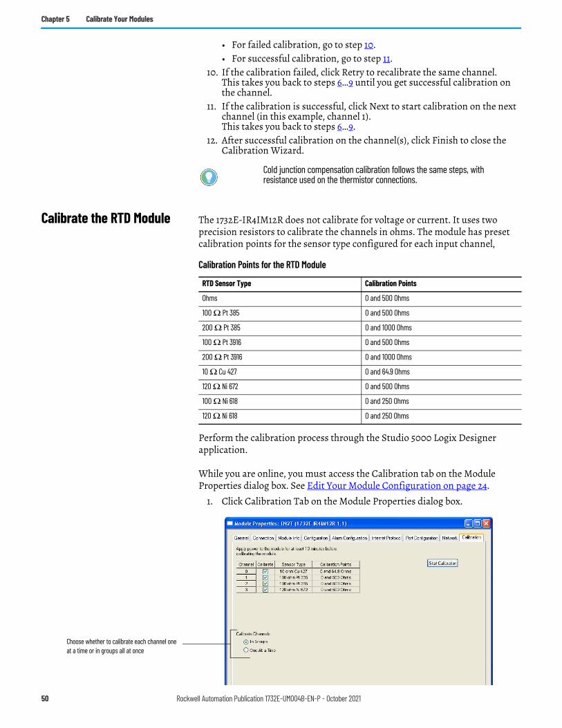
Chapter 5 Calibrate Your Modules
• For failed calibration, go to step 10.• For successful calibration, go to step 11.
10. If the calibration failed, click Retry to recalibrate the same channel.This takes you back to steps 6…9 until you get successful calibration on the channel.
11. If the calibration is successful, click Next to start calibration on the next channel (in this example, channel 1). This takes you back to steps 6…9.
12. After successful calibration on the channel(s), click Finish to close the Calibration Wizard.
Calibrate the RTD Module The 1732E-IR4IM12R does not calibrate for voltage or current. It uses two precision resistors to calibrate the channels in ohms. The module has preset calibration points for the sensor type configured for each input channel,
Perform the calibration process through the Studio 5000 Logix Designer application.
While you are online, you must access the Calibration tab on the Module Properties dialog box. See Edit Your Module Configuration on page 24.
1. Click Calibration Tab on the Module Properties dialog box.
Cold junction compensation calibration follows the same steps, with resistance used on the thermistor connections.
Calibration Points for the RTD Module
RTD Sensor Type Calibration Points
Ohms 0 and 500 Ohms
100 Ω Pt 385 0 and 500 Ohms
200 Ω Pt 385 0 and 1000 Ohms
100 Ω Pt 3916 0 and 500 Ohms
200 Ω Pt 3916 0 and 1000 Ohms
10 Ω Cu 427 0 and 64.9 Ohms
120 Ω Ni 672 0 and 500 Ohms
100 Ω Ni 618 0 and 250 Ohms
120 Ω Ni 618 0 and 250 Ohms
Choose whether to calibrate each channel one at a time or in groups all at once
50 Rockwell Automation Publication 1732E-UM004B-EN-P - October 2021
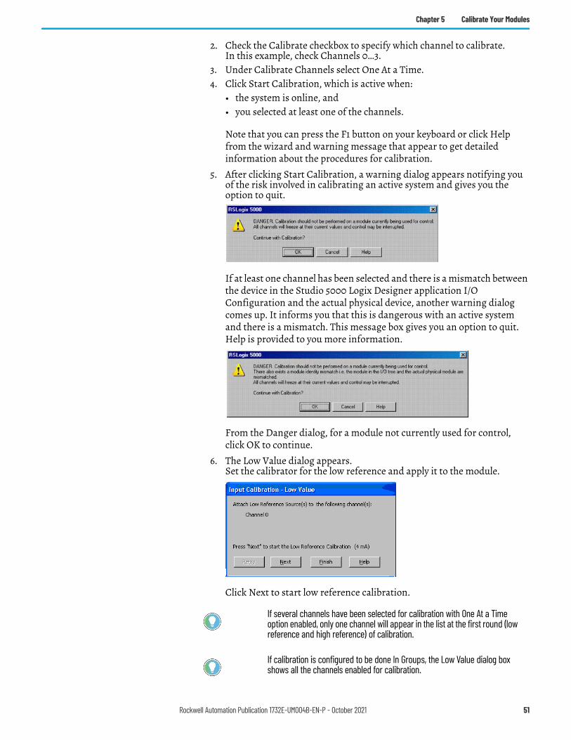
Chapter 5 Calibrate Your Modules
2. Check the Calibrate checkbox to specify which channel to calibrate. In this example, check Channels 0…3.
3. Under Calibrate Channels select One At a Time.4. Click Start Calibration, which is active when:
• the system is online, and• you selected at least one of the channels.
Note that you can press the F1 button on your keyboard or click Help from the wizard and warning message that appear to get detailed information about the procedures for calibration.
5. After clicking Start Calibration, a warning dialog appears notifying you of the risk involved in calibrating an active system and gives you the option to quit.
If at least one channel has been selected and there is a mismatch between the device in the Studio 5000 Logix Designer application I/O Configuration and the actual physical device, another warning dialog comes up. It informs you that this is dangerous with an active system and there is a mismatch. This message box gives you an option to quit. Help is provided to you more information.
From the Danger dialog, for a module not currently used for control, click OK to continue.
6. The Low Value dialog appears.Set the calibrator for the low reference and apply it to the module.
Click Next to start low reference calibration.
If several channels have been selected for calibration with One At a Time option enabled, only one channel will appear in the list at the first round (low reference and high reference) of calibration.
If calibration is configured to be done In Groups, the Low Value dialog box shows all the channels enabled for calibration.
Rockwell Automation Publication 1732E-UM004B-EN-P - October 2021 51
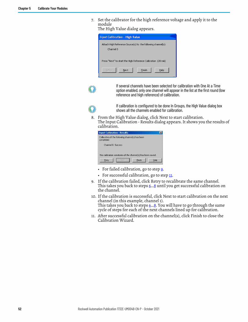
Chapter 5 Calibrate Your Modules
7. Set the calibrator for the high reference voltage and apply it to the moduleThe High Value dialog appears.
8. From the High Value dialog, click Next to start calibration.The Input Calibration - Results dialog appears. It shows you the results of calibration.
• For failed calibration, go to step 9.• For successful calibration, go to step 11.
9. If the calibration failed, click Retry to recalibrate the same channel.This takes you back to steps 6…8 until you get successful calibration on the channel.
10. If the calibration is successful, click Next to start calibration on the next channel (in this example, channel 1). This takes you back to steps 6…8. You will have to go through the same cycle of steps for each of the next channels lined up for calibration.
11. After successful calibration on the channel(s), click Finish to close the Calibration Wizard.
If several channels have been selected for calibration with One At a Time option enabled, only one channel will appear in the list at the first round (low reference and high reference) of calibration.
If calibration is configured to be done In Groups, the High Value dialog box shows all the channels enabled for calibration.
52 Rockwell Automation Publication 1732E-UM004B-EN-P - October 2021
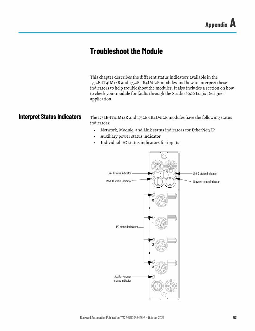
Appendix A
Troubleshoot the Module
This chapter describes the different status indicators available in the 1732E-IT4IM12R and 1732E-IR4IM12R modules and how to interpret these indicators to help troubleshoot the modules. It also includes a section on how to check your module for faults through the Studio 5000 Logix Designer application.
Interpret Status Indicators The 1732E-IT4IM12R and 1732E-IR4IM12R modules have the following status indicators:
• Network, Module, and Link status indicators for EtherNet/IP• Auxiliary power status indicator• Individual I/O status indicators for inputs
Link 2 status indicator
Network status indicatorModule status indicator
I/O status indicators
Auxiliary power status indicator
Link 1 status indicator
Rockwell Automation Publication 1732E-UM004B-EN-P - October 2021 53
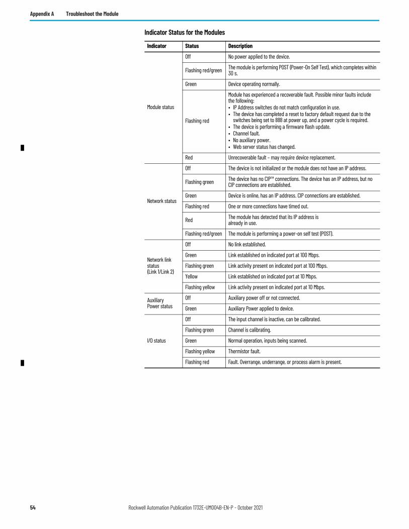
Appendix A Troubleshoot the Module
Indicator Status for the Modules
Indicator Status Description
Module status
Off No power applied to the device.
Flashing red/green The module is performing POST (Power-On Self Test), which completes within 30 s.
Green Device operating normally.
Flashing red
Module has experienced a recoverable fault. Possible minor faults include the following:• IP Address switches do not match configuration in use.• The device has completed a reset to factory default request due to the
switches being set to 888 at power up, and a power cycle is required.• The device is performing a firmware flash update.• Channel fault.• No auxiliary power.• Web server status has changed.
Red Unrecoverable fault – may require device replacement.
Network status
Off The device is not initialized or the module does not have an IP address.
Flashing green The device has no CIP™ connections. The device has an IP address, but no CIP connections are established.
Green Device is online, has an IP address. CIP connections are established.
Flashing red One or more connections have timed out.
Red The module has detected that its IP address is already in use.
Flashing red/green The module is performing a power-on self test (POST).
Network link status (Link 1/Link 2)
Off No link established.
Green Link established on indicated port at 100 Mbps.
Flashing green Link activity present on indicated port at 100 Mbps.
Yellow Link established on indicated port at 10 Mbps.
Flashing yellow Link activity present on indicated port at 10 Mbps.
AuxiliaryPower status
Off Auxiliary power off or not connected.
Green Auxiliary Power applied to device.
I/O status
Off The input channel is inactive, can be calibrated.
Flashing green Channel is calibrating.
Green Normal operation, inputs being scanned.
Flashing yellow Thermistor fault.
Flashing red Fault. Overrange, underrange, or process alarm is present.
54 Rockwell Automation Publication 1732E-UM004B-EN-P - October 2021
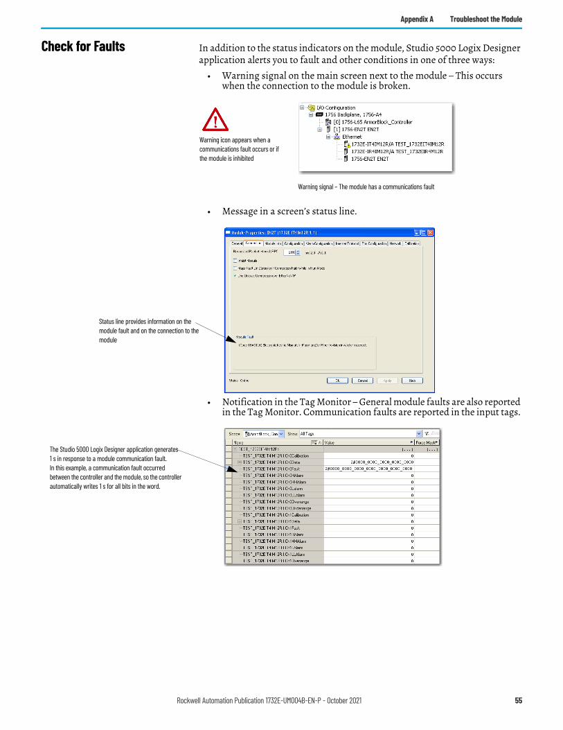
Appendix A Troubleshoot the Module
Check for Faults In addition to the status indicators on the module, Studio 5000 Logix Designer application alerts you to fault and other conditions in one of three ways:
• Warning signal on the main screen next to the module – This occurs when the connection to the module is broken.
• Message in a screen’s status line.
• Notification in the Tag Monitor – General module faults are also reported in the Tag Monitor. Communication faults are reported in the input tags.
Warning icon appears when a communications fault occurs or if the module is inhibited
Warning signal – The module has a communications fault
Status line provides information on the module fault and on the connection to the module
The Studio 5000 Logix Designer application generates 1 s in response to a module communication fault.In this example, a communication fault occurred between the controller and the module, so the controller automatically writes 1 s for all bits in the word.
Rockwell Automation Publication 1732E-UM004B-EN-P - October 2021 55

Appendix A Troubleshoot the Module
Notes:
56 Rockwell Automation Publication 1732E-UM004B-EN-P - October 2021
Appendix B
ArmorBlock Embedded Web Server
Introduction Rockwell Automation offers enhanced ArmorBlock I/O for your EtherNet/IP control systems so you can monitor data remotely from web pages.
Typical Applications The module provides access to internal and network diagnostics. This access opens up different, remote access applications to control systems. Use the ArmorBlock I/O web browser to remotely access module data. Use a web browser to monitor live module data and access diagnostic information.
Browser Requirements You can access the ArmorBlock I/O web pages only with Internet Explorer 6.0 or higher. To access data view pages, the browser requires Javascript support.
The supported display size is 640 x 480 or greater. Smaller display sizes work but might require extensive scrolling to view the information.
Enable or Disable the Web Server
With firmware revision 1.013 or later, the web server feature is disabled by default. Use the network address switches to enable or disable the web server for your application.
Topic PageTypical Applications 57Browser Requirements 57Access the Home Page of the Web Server 58Log On to the Web Server 59Navigate the ArmorBlock I/O 59
IMPORTANT To reduce the likelihood of exploitation and associated security risk, we recommend that you keep the web server disabled.
Value Description
000Enables the web server.Cycle power to the module for the setting to take effect. When you apply power, the module LED flashes red to indicate that the web server is enabled.
901Disables the web server.Cycle power to the module for the setting to take effect. When you apply power, the module LED flashes red to indicate that the web server is disabled.
Rockwell Automation Publication 1732E-UM004B-EN-P - October 2021 57
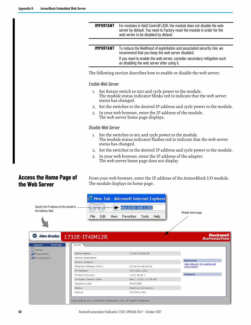
Appendix B ArmorBlock Embedded Web Server
The following section describes how to enable or disable the web server.
Enable Web Server1. Set Rotary switch to 000 and cycle power to the module.
The module status indicator blinks red to indicate that the web serverstatus has changed.
2. Set the switches to the desired IP address and cycle power to the module.3. In your web browser, enter the IP address of the module.
The web server home page displays.
Disable Web Server1. Set the switches to 901 and cycle power to the module.
The module status indicator flashes red to indicate that the web serverstatus has changed.
2. Set the switches to the desired IP address and cycle power to the module.3. In your web browser, enter the IP address of the adapter.
The web server home page does not display
Access the Home Page of the Web Server
From your web browser, enter the IP address of the ArmorBlock I/O module. The module displays its home page.
IMPORTANT For modules in field ControlFLASH, the module does not disable the web server by default. You need to Factory reset the module in order for the web server to be disabled by default.
IMPORTANT To reduce the likelihood of exploitation and associated security risk, we recommend that you keep the web server disabled.If you need to enable the web server, consider secondary mitigation such as disabling the web server after using it.
Specify the IP address of the module in the Address field. Module home page
58 Rockwell Automation Publication 1732E-UM004B-EN-P - October 2021
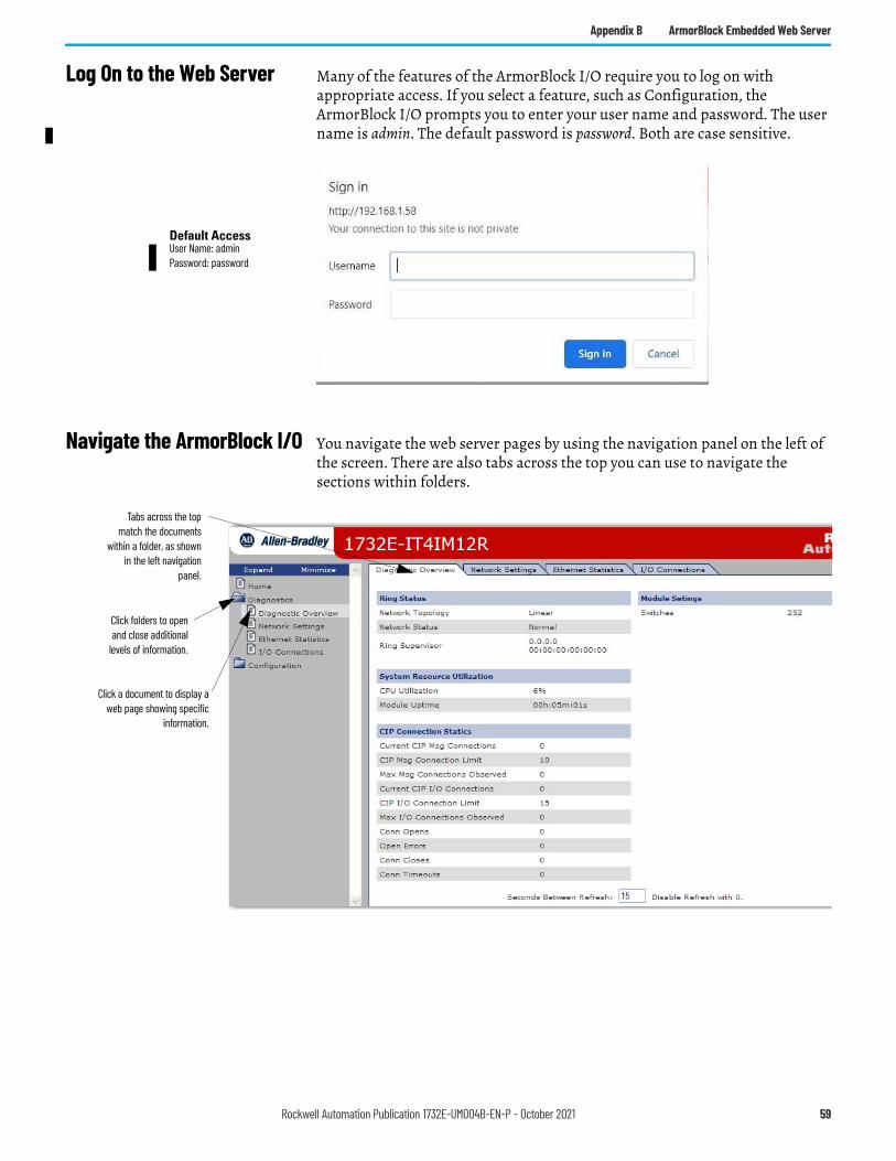
Appendix B ArmorBlock Embedded Web Server
Log On to the Web Server Many of the features of the ArmorBlock I/O require you to log on with appropriate access. If you select a feature, such as Configuration, the ArmorBlock I/O prompts you to enter your user name and password. The user name is admin. The default password is password. Both are case sensitive.
Navigate the ArmorBlock I/O You navigate the web server pages by using the navigation panel on the left ofthe screen. There are also tabs across the top you can use to navigate the sections within folders.
Default AccessUser Name: adminPassword: password
Click folders to openand close additional
levels of information.
Click a document to display aweb page showing specific
information.
Tabs across the topmatch the documents
within a folder, as shownin the left navigation
panel.
Rockwell Automation Publication 1732E-UM004B-EN-P - October 2021 59
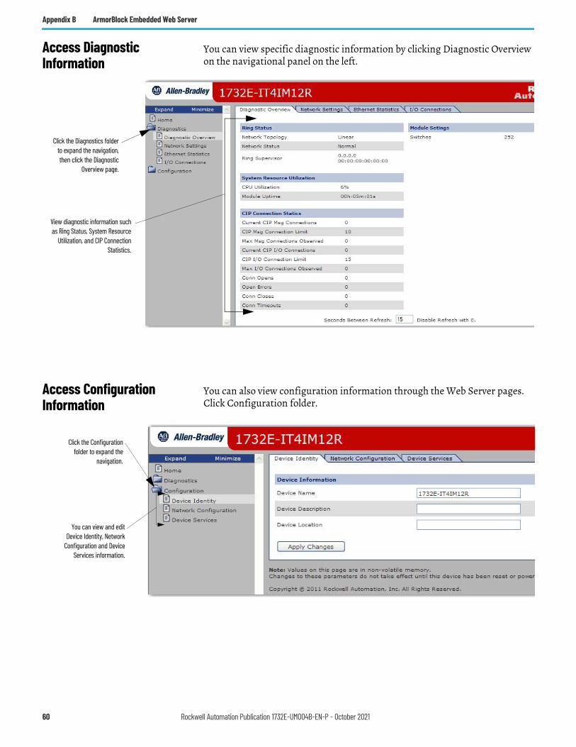
Appendix B ArmorBlock Embedded Web Server
Access Diagnostic Information
You can view specific diagnostic information by clicking Diagnostic Overview on the navigational panel on the left.
Access Configuration Information
You can also view configuration information through the Web Server pages. Click Configuration folder.
Click the Diagnostics folderto expand the navigation,then click the Diagnostic
Overview page.
View diagnostic information suchas Ring Status, System Resource
Utilization, and CIP ConnectionStatistics.
Click the Configurationfolder to expand the
navigation.
You can view and editDevice Identity, Network
Configuration and DeviceServices information.
60 Rockwell Automation Publication 1732E-UM004B-EN-P - October 2021
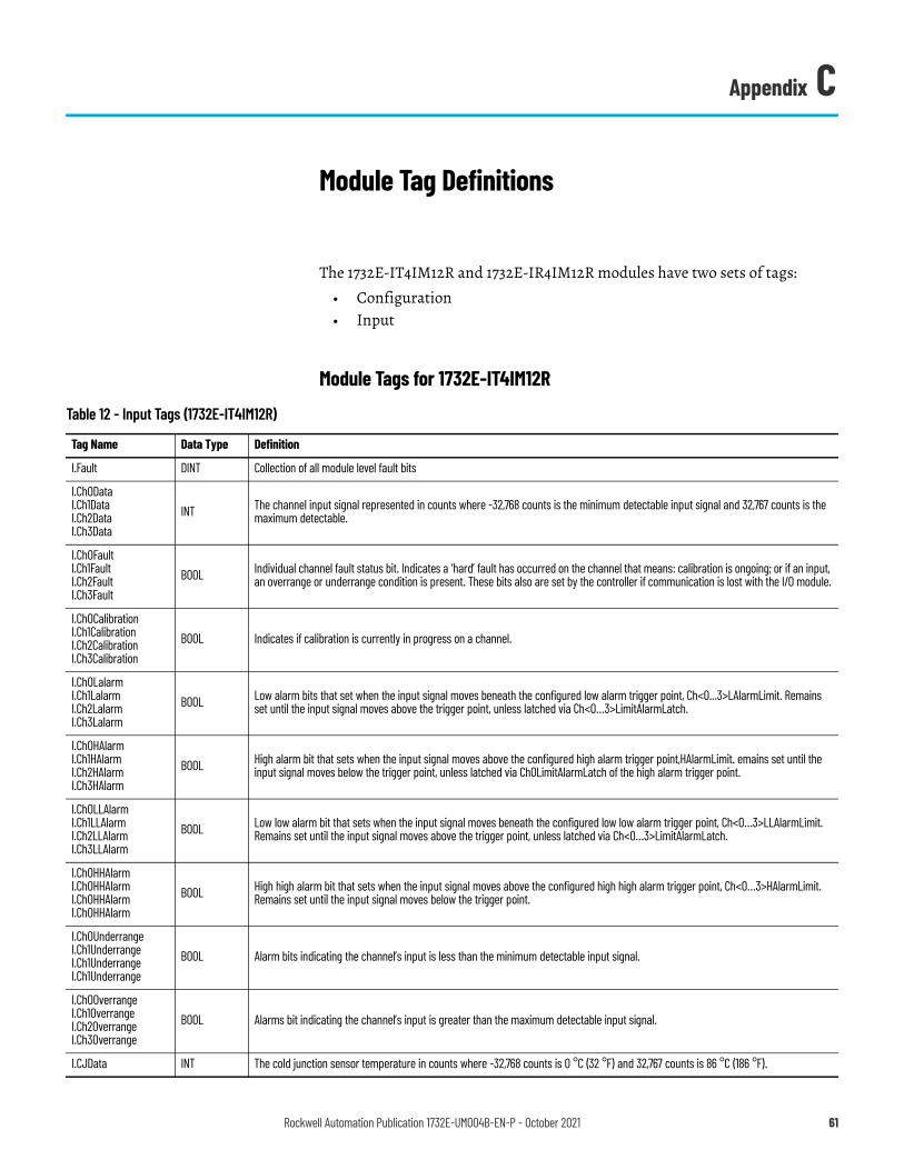
Appendix C
Module Tag Definitions
The 1732E-IT4IM12R and 1732E-IR4IM12R modules have two sets of tags:• Configuration• Input
Module Tags for 1732E-IT4IM12R
Table 12 - Input Tags (1732E-IT4IM12R)
Tag Name Data Type Definition
I.Fault DINT Collection of all module level fault bits
I.Ch0DataI.Ch1DataI.Ch2DataI.Ch3Data
INT The channel input signal represented in counts where -32,768 counts is the minimum detectable input signal and 32,767 counts is the maximum detectable.
I.Ch0FaultI.Ch1FaultI.Ch2FaultI.Ch3Fault
BOOL Individual channel fault status bit. Indicates a ‘hard’ fault has occurred on the channel that means: calibration is ongoing; or if an input, an overrange or underrange condition is present. These bits also are set by the controller if communication is lost with the I/O module.
I.Ch0CalibrationI.Ch1CalibrationI.Ch2CalibrationI.Ch3Calibration
BOOL Indicates if calibration is currently in progress on a channel.
I.Ch0LalarmI.Ch1LalarmI.Ch2LalarmI.Ch3Lalarm
BOOL Low alarm bits that set when the input signal moves beneath the configured low alarm trigger point, Ch<0...3>LAlarmLimit. Remains set until the input signal moves above the trigger point, unless latched via Ch<0…3>LimitAlarmLatch.
I.Ch0HAlarmI.Ch1HAlarmI.Ch2HAlarmI.Ch3HAlarm
BOOL High alarm bit that sets when the input signal moves above the configured high alarm trigger point,HAlarmLimit. emains set until the input signal moves below the trigger point, unless latched via Ch0LimitAlarmLatch of the high alarm trigger point.
I.Ch0LLAlarmI.Ch1LLAlarmI.Ch2LLAlarmI.Ch3LLAlarm
BOOL Low low alarm bit that sets when the input signal moves beneath the configured low low alarm trigger point, Ch<0…3>LLAlarmLimit. Remains set until the input signal moves above the trigger point, unless latched via Ch<0…3>LimitAlarmLatch.
I.Ch0HHAlarmI.Ch0HHAlarmI.Ch0HHAlarmI.Ch0HHAlarm
BOOL High high alarm bit that sets when the input signal moves above the configured high high alarm trigger point, Ch<0…3>HAlarmLimit. Remains set until the input signal moves below the trigger point.
I.Ch0UnderrangeI.Ch1UnderrangeI.Ch1UnderrangeI.Ch1Underrange
BOOL Alarm bits indicating the channel’s input is less than the minimum detectable input signal.
I.Ch0OverrangeI.Ch1OverrangeI.Ch2OverrangeI.Ch3Overrange
BOOL Alarms bit indicating the channel’s input is greater than the maximum detectable input signal.
I.CJData INT The cold junction sensor temperature in counts where -32,768 counts is 0 °C (32 °F) and 32,767 counts is 86 °C (186 °F).
Rockwell Automation Publication 1732E-UM004B-EN-P - October 2021 61
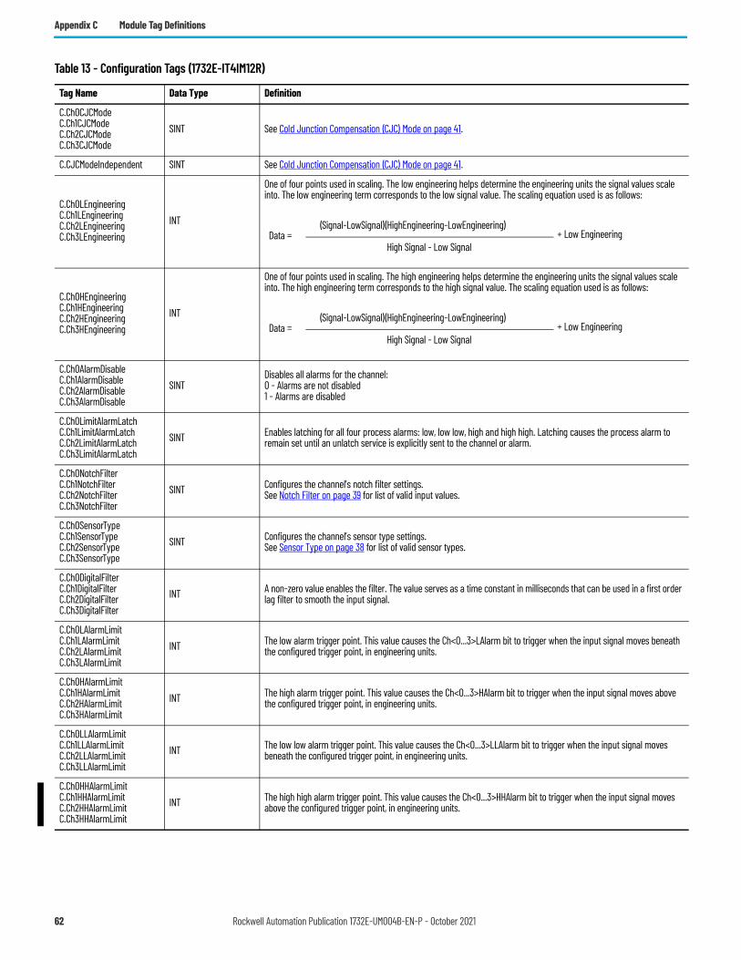
Appendix C Module Tag Definitions
Table 13 - Configuration Tags (1732E-IT4IM12R)
Tag Name Data Type Definition
C.Ch0CJCModeC.Ch1CJCModeC.Ch2CJCModeC.Ch3CJCMode
SINT See Cold Junction Compensation (CJC) Mode on page 41.
C.CJCModeIndependent SINT See Cold Junction Compensation (CJC) Mode on page 41.
C.Ch0LEngineeringC.Ch1LEngineeringC.Ch2LEngineeringC.Ch3LEngineering
INT
One of four points used in scaling. The low engineering helps determine the engineering units the signal values scale into. The low engineering term corresponds to the low signal value. The scaling equation used is as follows:
C.Ch0HEngineeringC.Ch1HEngineeringC.Ch2HEngineeringC.Ch3HEngineering
INT
One of four points used in scaling. The high engineering helps determine the engineering units the signal values scale into. The high engineering term corresponds to the high signal value. The scaling equation used is as follows:
C.Ch0AlarmDisableC.Ch1AlarmDisableC.Ch2AlarmDisableC.Ch3AlarmDisable
SINTDisables all alarms for the channel:0 - Alarms are not disabled1 - Alarms are disabled
C.Ch0LimitAlarmLatchC.Ch1LimitAlarmLatchC.Ch2LimitAlarmLatchC.Ch3LimitAlarmLatch
SINT Enables latching for all four process alarms: low, low low, high and high high. Latching causes the process alarm to remain set until an unlatch service is explicitly sent to the channel or alarm.
C.Ch0NotchFilterC.Ch1NotchFilterC.Ch2NotchFilterC.Ch3NotchFilter
SINT Configures the channel’s notch filter settings.See Notch Filter on page 39 for list of valid input values.
C.Ch0SensorTypeC.Ch1SensorTypeC.Ch2SensorTypeC.Ch3SensorType
SINT Configures the channel’s sensor type settings.See Sensor Type on page 38 for list of valid sensor types.
C.Ch0DigitalFilterC.Ch1DigitalFilterC.Ch2DigitalFilterC.Ch3DigitalFilter
INT A non-zero value enables the filter. The value serves as a time constant in milliseconds that can be used in a first order lag filter to smooth the input signal.
C.Ch0LAlarmLimitC.Ch1LAlarmLimitC.Ch2LAlarmLimitC.Ch3LAlarmLimit
INT The low alarm trigger point. This value causes the Ch<0...3>LAlarm bit to trigger when the input signal moves beneath the configured trigger point, in engineering units.
C.Ch0HAlarmLimitC.Ch1HAlarmLimitC.Ch2HAlarmLimitC.Ch3HAlarmLimit
INT The high alarm trigger point. This value causes the Ch<0...3>HAlarm bit to trigger when the input signal moves above the configured trigger point, in engineering units.
C.Ch0LLAlarmLimitC.Ch1LLAlarmLimitC.Ch2LLAlarmLimitC.Ch3LLAlarmLimit
INT The low low alarm trigger point. This value causes the Ch<0...3>LLAlarm bit to trigger when the input signal moves beneath the configured trigger point, in engineering units.
C.Ch0HHAlarmLimitC.Ch1HHAlarmLimitC.Ch2HHAlarmLimitC.Ch3HHAlarmLimit
INT The high high alarm trigger point. This value causes the Ch<0...3>HHAlarm bit to trigger when the input signal moves above the configured trigger point, in engineering units.
Data = (Signal-LowSignal)(HighEngineering-LowEngineering)
High Signal - Low Signal+ Low Engineering
Data = (Signal-LowSignal)(HighEngineering-LowEngineering)
High Signal - Low Signal+ Low Engineering
62 Rockwell Automation Publication 1732E-UM004B-EN-P - October 2021
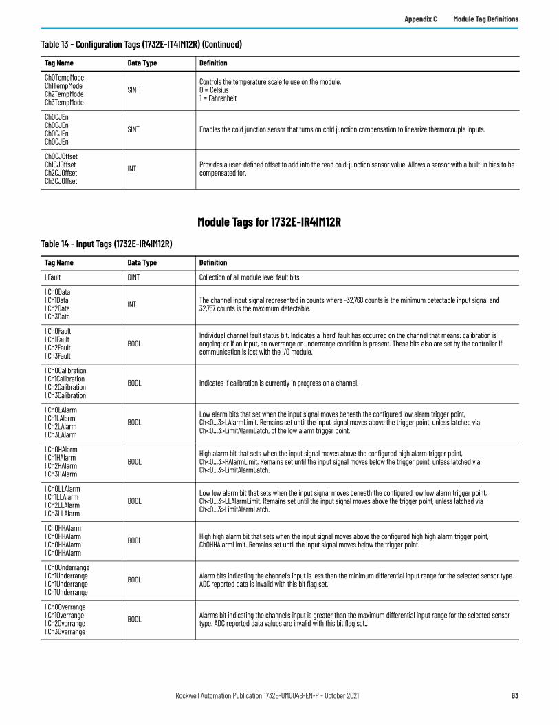
Appendix C Module Tag Definitions
Module Tags for 1732E-IR4IM12R
Ch0TempModeCh1TempModeCh2TempModeCh3TempMode
SINTControls the temperature scale to use on the module.0 = Celsius1 = Fahrenheit
Ch0CJEnCh0CJEnCh0CJEnCh0CJEn
SINT Enables the cold junction sensor that turns on cold junction compensation to linearize thermocouple inputs.
Ch0CJOffsetCh1CJOffsetCh2CJOffsetCh3CJOffset
INT Provides a user-defined offset to add into the read cold-junction sensor value. Allows a sensor with a built-in bias to be compensated for.
Table 13 - Configuration Tags (1732E-IT4IM12R) (Continued)
Tag Name Data Type Definition
Table 14 - Input Tags (1732E-IR4IM12R)
Tag Name Data Type Definition
I.Fault DINT Collection of all module level fault bits
I.Ch0DataI.Ch1DataI.Ch2DataI.Ch3Data
INT The channel input signal represented in counts where -32,768 counts is the minimum detectable input signal and 32,767 counts is the maximum detectable.
I.Ch0FaultI.Ch1FaultI.Ch2FaultI.Ch3Fault
BOOLIndividual channel fault status bit. Indicates a ‘hard’ fault has occurred on the channel that means: calibration is ongoing; or if an input, an overrange or underrange condition is present. These bits also are set by the controller if communication is lost with the I/O module.
I.Ch0CalibrationI.Ch1CalibrationI.Ch2CalibrationI.Ch3Calibration
BOOL Indicates if calibration is currently in progress on a channel.
I.Ch0LAlarmI.Ch1LAlarmI.Ch2LAlarmI.Ch3LAlarm
BOOLLow alarm bits that set when the input signal moves beneath the configured low alarm trigger point, Ch<0...3>LAlarmLimit. Remains set until the input signal moves above the trigger point, unless latched via Ch<0...3>LimitAlarmLatch, of the low alarm trigger point.
I.Ch0HAlarmI.Ch1HAlarmI.Ch2HAlarmI.Ch3HAlarm
BOOLHigh alarm bit that sets when the input signal moves above the configured high alarm trigger point, Ch<0...3>HAlarmLimit. Remains set until the input signal moves below the trigger point, unless latched via Ch<0...3>LimitAlarmLatch.
I.Ch0LLAlarmI.Ch1LLAlarmI.Ch2LLAlarmI.Ch3LLAlarm
BOOLLow low alarm bit that sets when the input signal moves beneath the configured low low alarm trigger point, Ch<0...3>LLAlarmLimit. Remains set until the input signal moves above the trigger point, unless latched via Ch<0...3>LimitAlarmLatch.
I.Ch0HHAlarmI.Ch0HHAlarmI.Ch0HHAlarmI.Ch0HHAlarm
BOOL High high alarm bit that sets when the input signal moves above the configured high high alarm trigger point, Ch0HHAlarmLimit. Remains set until the input signal moves below the trigger point.
I.Ch0UnderrangeI.Ch1UnderrangeI.Ch1UnderrangeI.Ch1Underrange
BOOL Alarm bits indicating the channel’s input is less than the minimum differential input range for the selected sensor type. ADC reported data is invalid with this bit flag set.
I.Ch0OverrangeI.Ch1OverrangeI.Ch2OverrangeI.Ch3Overrange
BOOL Alarms bit indicating the channel’s input is greater than the maximum differential input range for the selected sensor type. ADC reported data values are invalid with this bit flag set..
Rockwell Automation Publication 1732E-UM004B-EN-P - October 2021 63
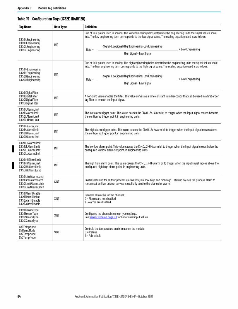
Appendix C Module Tag Definitions
Table 15 - Configuration Tags (1732E-IR4IM12R)
Tag Name Data Type Definition
C.Ch0LEngineeringC.Ch1LEngineeringC.Ch2LEngineeringC.Ch3LEngineering
INT
One of four points used in scaling. The low engineering helps determine the engineering units the signal values scale into. The low engineering term corresponds to the low signal value. The scaling equation used is as follows:
C.Ch0HEngineeringC.Ch1HEngineeringC.Ch2HEngineeringC.Ch3HEngineering
INT
One of four points used in scaling. The high engineering helps determine the engineering units the signal values scale into. The high engineering term corresponds to the high signal value. The scaling equation used is as follows:
C.Ch0DigitalFilterC.Ch1DigitalFilterC.Ch2DigitalFilterC.Ch3DigitalFilter
INT A non-zero value enables the filter. The value serves as a time constant in milliseconds that can be used in a first order lag filter to smooth the input signal.
C.Ch0LAlarmLimitC.Ch1LAlarmLimitC.Ch2LAlarmLimitC.Ch3LAlarmLimit
INT The low alarm trigger point. This value causes the Ch<0...3>LAlarm bit to trigger when the input signal moves beneath the configured trigger point, in engineering units.
C.Ch0HAlarmLimitC.Ch1HAlarmLimitC.Ch2HAlarmLimitC.Ch3HAlarmLimit
INT The high alarm trigger point. This value causes the Ch<0...3>HAlarm bit to trigger when the input signal moves above the configured trigger point, in engineering units.
C.Ch0LLAlarmLimitC.Ch1LLAlarmLimitC.Ch2LLAlarmLimitC.Ch3LLAlarmLimit
INT The low low alarm point. This value causes the Ch<0...3>HHAlarm bit to trigger when the input signal moves below the configured low low alarm set point, in engineering units.
C.Ch0HHAlarmLimitC.Ch1HHAlarmLimitC.Ch2HHAlarmLimitC.Ch3HHAlarmLimit
INT The high high alarm point. This value causes the Ch<0...3>HHAlarm bit to trigger when the input signal moves above the configured high high alarm point, in engineering units.
C.Ch0LimitAlarmLatchC.Ch1LimitAlarmLatchC.Ch2LimitAlarmLatchC.Ch3LimitAlarmLatch
SINT Enables latching for all four process alarms: low, low low, high and high high. Latching causes the process alarm to remain set until an unlatch service is explicitly sent to the channel or alarm.
C.Ch0AlarmDisableC.Ch1AlarmDisableC.Ch2AlarmDisableC.Ch3AlarmDisable
SINTDisables all alarms for the channel:0 - Alarms are not disabled1 - Alarms are disabled
C.Ch0SensorTypeC.Ch1SensorTypeC.Ch2SensorTypeC.Ch3SensorType
SINT Configures the channel’s sensor type settings.See Sensor Type on page 38 for list of valid input values.
Ch0TempModeCh1TempModeCh2TempModeCh3TempMode
SINTControls the temperature scale to use on the module.0 = Celsius1 = Fahrenheit
Data = (Signal-LowSignal)(HighEngineering-LowEngineering)
High Signal - Low Signal+ Low Engineering
Data = (Signal-LowSignal)(HighEngineering-LowEngineering)
High Signal - Low Signal+ Low Engineering
64 Rockwell Automation Publication 1732E-UM004B-EN-P - October 2021
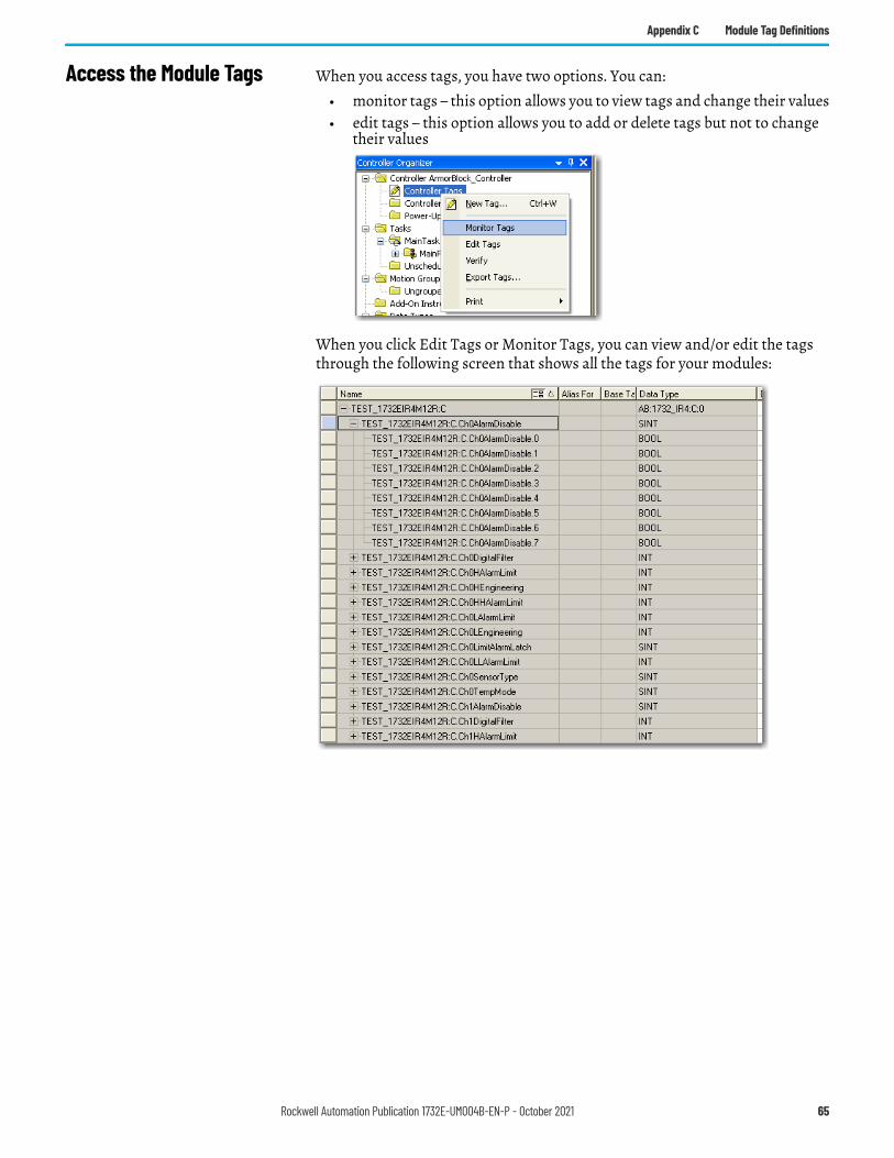
Appendix C Module Tag Definitions
Access the Module Tags When you access tags, you have two options. You can:• monitor tags – this option allows you to view tags and change their values• edit tags – this option allows you to add or delete tags but not to change
their values
When you click Edit Tags or Monitor Tags, you can view and/or edit the tags through the following screen that shows all the tags for your modules:
Rockwell Automation Publication 1732E-UM004B-EN-P - October 2021 65

Appendix C Module Tag Definitions
Notes:
66 Rockwell Automation Publication 1732E-UM004B-EN-P - October 2021
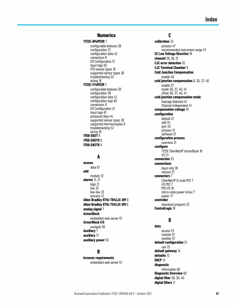
Index
Numerics1732E-IR4IM12R 7
configurable features 38configuration 27configuration data 43connectors 8I/O Configuration 21input tags 63RTD sensor types 10supported sensor types 39troubleshooting 53wiring 16
1732E-IT4IM12R 7configurable features 38configuration 29configuration data 41configuration tags 62connectors 8I/O Configuration 21input tags 61produced data 44supported sensor types 38supported thermocouples 9troubleshooting 53wiring 16
1756-EN2T 91756-EN2TR 91756-EN3TR 9
Aaccess
data 57add
module 22alarms 11, 31
high 31low 32low-low 32process 31
Allen-Bradley 871A-TR4CJC-DM 9Allen-Bradley 871A-TS4CJC-DM 9analog signal 7ArmorBlock
embedded web server 57ArmorBlock I/O
navigate 59Auxiliary 7auxiliary 17auxiliary power 53
Bbrowser requirements
embedded web server 57
Ccalibration 33
process 47recommended instrument range 47
CE Low Voltage Directive 18channel 28, 29, 31CJC error detection 10CJC Terminal Chamber 9Cold Junction Compensation
enable 40cold junction compensation 9, 30, 37, 40
enable 37mode 30, 37, 40, 41offset 30, 37, 40, 41
cold junction compensation modeAverage Selected 41Channel Independent 41
compensation voltage 10configuration
default 21edit 24port 33process 21software 21
configuration processoverview 21
configure1732E EtherNet/IP ArmorBlock 19I/O 21
connection 23connections
input only 26unicast 27
connectors 7EtherNet/IP D-code M12 7I/O M12 7M12 I/O 16micro-style power in/out 7power 17
controllerdownload program 23
ControlLogix 19
Ddata
access 57module 57monitor 57
default configuration 21use 22
default gateway 14defaults 13DHCP 13diagnostic
information 60Diagnostic Overview 60digital filter 28, 30, 40digital filters 11
Rockwell Automation Publication 1732E-UM004B-EN-P - October 2021 67
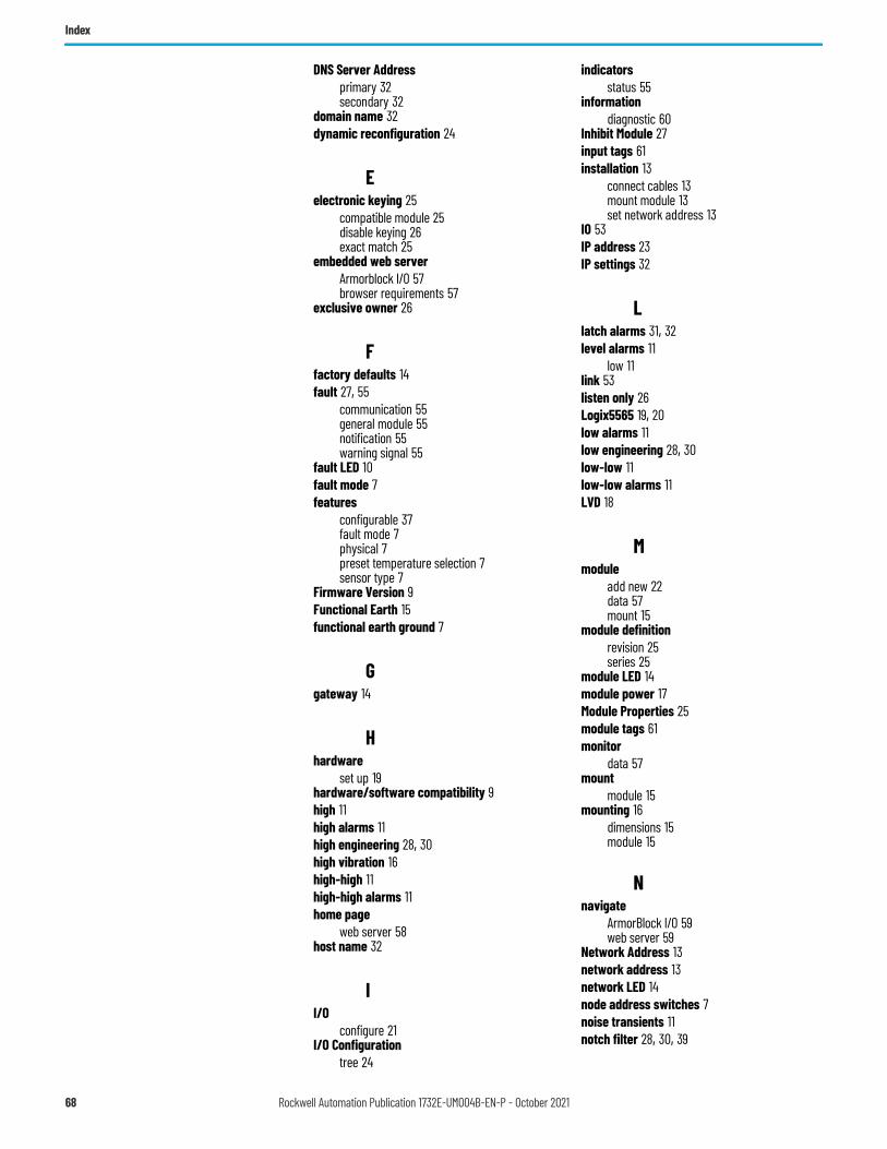
Index
DNS Server Addressprimary 32secondary 32
domain name 32dynamic reconfiguration 24
Eelectronic keying 25
compatible module 25disable keying 26exact match 25
embedded web serverArmorblock I/O 57browser requirements 57
exclusive owner 26
Ffactory defaults 14fault 27, 55
communication 55general module 55notification 55warning signal 55
fault LED 10fault mode 7features
configurable 37fault mode 7physical 7preset temperature selection 7sensor type 7
Firmware Version 9Functional Earth 15functional earth ground 7
Ggateway 14
Hhardware
set up 19hardware/software compatibility 9high 11high alarms 11high engineering 28, 30high vibration 16high-high 11high-high alarms 11home page
web server 58host name 32
II/O
configure 21I/O Configuration
tree 24
indicatorsstatus 55
informationdiagnostic 60
Inhibit Module 27input tags 61installation 13
connect cables 13mount module 13set network address 13
IO 53IP address 23IP settings 32
Llatch alarms 31, 32level alarms 11
low 11link 53listen only 26Logix5565 19, 20low alarms 11low engineering 28, 30low-low 11low-low alarms 11LVD 18
Mmodule
add new 22data 57mount 15
module definitionrevision 25series 25
module LED 14module power 17Module Properties 25module tags 61monitor
data 57mount
module 15mounting 16
dimensions 15module 15
Nnavigate
ArmorBlock I/O 59web server 59
Network Address 13network address 13network LED 14node address switches 7noise transients 11notch filter 28, 30, 39
68 Rockwell Automation Publication 1732E-UM004B-EN-P - October 2021
Index
Ooverrange detection 7, 11overview
configuration process 21
Ppan head screws 15PELV 18physical features 7port configuration 33port speed
configure 33power
connectors 17process
configuration 21purpose of this manual 5
Rredundancy
use 21requested packet interval (RPI) 26RSLinx 9RSLinx software 20RTD module 7RTD sensor type 10, 28RTD types 10
Sscrews 16SELV 18sensor type 7, 28, 30, 37sensor types 38set up
hardware 19setting 13software
configuration 21Software Release 9Status indicator
flashing red 54flashing red/green 54flashing yellow 54green 54red 54
status indicators 7, 53auxiliary power 7, 54I/O 7, 54link 7, 54module 7, 53, 54network 7, 53, 54
status monitoring 34
Studio 5000 Logix Designer 19, 21, 22, 24, 47, 53, 55
Calibration tab 33Configuration tab 27Connection tab 26General tab 25I/O Configuration 19Internet Protocol tab 32Port Configuration tab 33use 21
switches 7, 13001 14888 14
Ttemperature
units 30, 37, 39thermistor 41thermistors 10Thermocouple module 7thermocouple types 9torque 16Transport Control Protocol 14troubleshoot 55troubleshoot module 55troubleshooting 53
UUL Type 1 enclosure 18underrange detection 7, 11use
default configuration 22redundancy 21screw holes 15Studio 5000 Logix Designer 21
Vvibration areas 16
WWeb Server
home page 58web server 57, 58
log in 59wiring 16
Rockwell Automation Publication 1732E-UM004B-EN-P - October 2021 69

Index
Notes:
70 Rockwell Automation Publication 1732E-UM004B-EN-P - October 2021

Rockwell Automation Publication 1732E-UM004B-EN-P - October 2021 71
ArmorBlock Dual-port EtherNet/IP 4-point Isolated Thermocouple and RTD Input Modules User Manual

Publication 1732E-UM004B-EN-P - October 2021Supersedes Publication 1732E-UM004A-EN-P - July 2012 Copyright © 2021 Rockwell Automation, Inc. All rights reserved.
Rockwell Automation Support
Use these resources to access support information.
Documentation Feedback
Your comments help us serve your documentation needs better. If you have any suggestions on how to improve our content, complete the form at rok.auto/docfeedback.
Waste Electrical and Electronic Equipment (WEEE)
Rockwell Automation maintains current product environmental information on its website at rok.auto/pec.
Technical Support Center Find help with how-to videos, FAQs, chat, user forums, and product notification updates. rok.auto/supportKnowledgebase Access Knowledgebase articles. rok.auto/knowledgebaseLocal Technical Support Phone Numbers Locate the telephone number for your country. rok.auto/phonesupportLiterature Library Find installation instructions, manuals, brochures, and technical data publications. rok.auto/literatureProduct Compatibility and Download Center (PCDC)
Download firmware, associated files (such as AOP, EDS, and DTM), and access product release notes. rok.auto/pcdc
At the end of life, this equipment should be collected separately from any unsorted municipal waste.
Rockwell Otomasyon Ticaret A.Ş. Kar Plaza İş Merkezi E Blok Kat:6 34752, İçerenkÖy, İstanbul, Tel: +90 (216) 5698400 EEE YÖnetmeliğine Uygundur
Connect with us.
Allen-Bradley, ArmorBlock, ControlFLASH, ControlLogix, expanding human possibility, FactoryTalk, Logix 5000, Rockwell Automation, RSLinx, RSLogix 5000, Studio 5000 Logix Designer, and TechConnect are trademarks of Rockwell Automation, Inc.CIP and EtherNet/IP are trademarks of ODVA, Inc.Trademarks not belonging to Rockwell Automation are property of their respective companies.