Embed Size (px)
Citation preview
172-65237MA-01 (J10) 12 June 2015
Float Dynamic Steam Trap
J10
Copyright © 2015 by TLV CO., LTD.
All rights reserved
ISO 9001/ ISO 14001
Manufacturer
Kakogawa, Japan is approved by LRQA LTD. to ISO 9001/14001

172-65237MA-01 (J10) 12 Jun 2015
1
Contents
Introduction ........................................................................ 1 Safety Considerations ........................................................ 2 Checking the Piping ........................................................... 4 Specifications ..................................................................... 4 Operation ........................................................................... 5 Configuration ...................................................................... 6 Installation .......................................................................... 7 Operation ........................................................................... 8 Lock Release Valve Operation ........................................... 8 Maintenance ....................................................................... 9 Disassembly / Reassembly .............................................. 10 Troubleshooting ............................................................... 13 Product Warranty ............................................................. 14 Introduction Thank you for purchasing the float dynamic steam trap.
This product has been thoroughly inspected before being shipped from the factory. When the product is delivered, before doing anything else, check the specifications and external appearance to make sure nothing is out of the ordinary. Also be sure to read this manual carefully before use and follow the instructions to be sure of using the product properly.
This steam trap is designed to automatically discharge condensate from the steam space. This trap is ideal for use on heaters or dryers or other steam equipment on applications where large quantities of condensate are generated.
If detailed instructions for special order specifications or options not contained in this manual are required, please contact for full details. This instruction manual is intended for use with the model(s) listed on the front cover. It is necessary not only for installation, but for subsequent maintenance, disassembly/reassembly and troubleshooting. Please keep it in a safe place for future reference.
172-65237MA-01 (J10) 12 Jun 2015
2
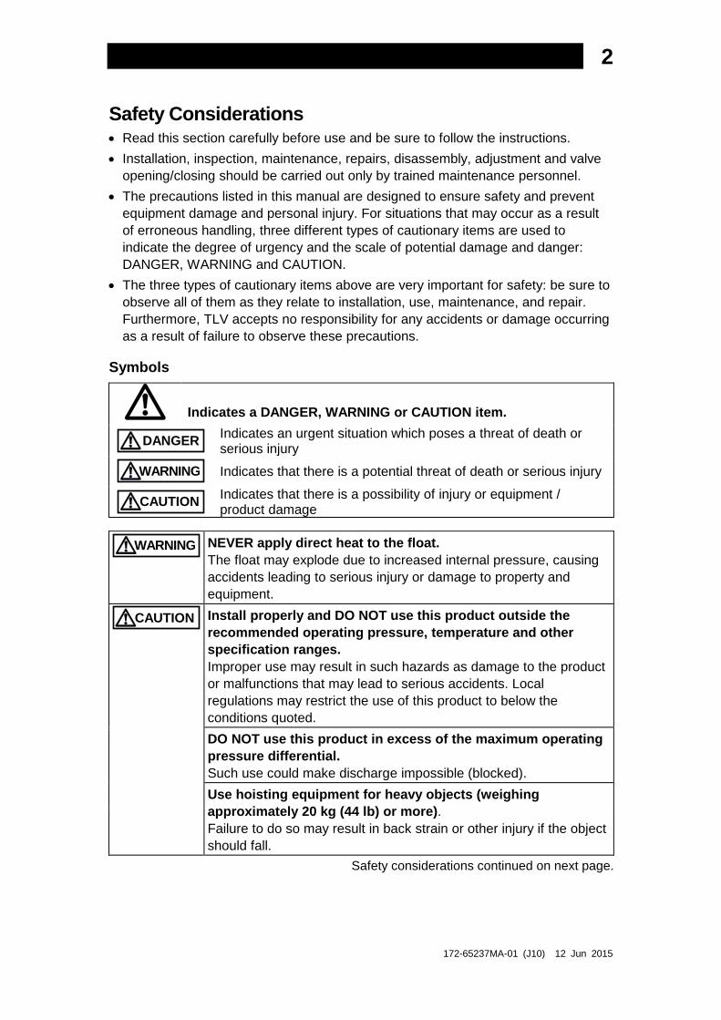
Safety Considerations • Read this section carefully before use and be sure to follow the instructions. • Installation, inspection, maintenance, repairs, disassembly, adjustment and valve
opening/closing should be carried out only by trained maintenance personnel. • The precautions listed in this manual are designed to ensure safety and prevent
equipment damage and personal injury. For situations that may occur as a result of erroneous handling, three different types of cautionary items are used to indicate the degree of urgency and the scale of potential damage and danger: DANGER, WARNING and CAUTION.
• The three types of cautionary items above are very important for safety: be sure to observe all of them as they relate to installation, use, maintenance, and repair. Furthermore, TLV accepts no responsibility for any accidents or damage occurring as a result of failure to observe these precautions.
Symbols
Indicates a DANGER, WARNING or CAUTION item.
DANGER Indicates an urgent situation which poses a threat of death or serious injury
WARNING Indicates that there is a potential threat of death or serious injury
CAUTION Indicates that there is a possibility of injury or equipment / product damage
WARNING NEVER apply direct heat to the float. The float may explode due to increased internal pressure, causing accidents leading to serious injury or damage to property and equipment.
CAUTION Install properly and DO NOT use this product outside the recommended operating pressure, temperature and other specification ranges. Improper use may result in such hazards as damage to the product or malfunctions that may lead to serious accidents. Local regulations may restrict the use of this product to below the conditions quoted.
DO NOT use this product in excess of the maximum operating pressure differential. Such use could make discharge impossible (blocked).
Use hoisting equipment for heavy objects (weighing approximately 20 kg (44 lb) or more). Failure to do so may result in back strain or other injury if the object should fall.
Safety considerations continued on next page.

172-65237MA-01 (J10) 12 Jun 2015
3
CAUTION Take measures to prevent people from coming into direct contact with product outlets. Failure to do so may result in burns or other injury from the discharge of fluids. When disassembling or removing the product, wait until the internal pressure equals atmospheric pressure and the surface of the product has cooled to room temperature. Disassembling or removing the product when it is hot or under pressure may lead to discharge of fluids, causing burns, other injuries or damage.
Be sure to use only the recommended components when repairing the product, and NEVER attempt to modify the product in any way. Failure to observe these precautions may result in damage to the product and burns or other injury due to malfunction or the discharge of fluids.
Use only under conditions in which no freeze-up will occur. Freezing may damage the product, leading to fluid discharge, which may cause burns or other injury.
Use only under conditions in which no water hammer will occur. The impact of water hammer may damage the product, leading to fluid discharge, which may cause burns or other injury.

172-65237MA-01 (J10) 12 Jun 2015
4
Checking the Piping
Use only under conditions in which no water hammer will occur. The impact of water hammer may damage the product, leading to fluid discharge, which may cause burns or other injury.
CAUTION
Check to make sure that the pipes to be connected to the trap have been installed properly.
1. Is the pipe diameter suitable? 2. Is the piping where the trap is to be installed horizontal? 3. Has sufficient space been secured for maintenance? 4. Have isolation valves been installed at the inlet and outlet? If the outlet is subject
to back pressure, has a check valve been installed? 5. Is the inlet pipe as short as possible, with as few bends as possible, and installed
so the liquid will flow naturally down into the trap? Specifications
Install properly and DO NOT use this product outside the recommended operating pressure, temperature and other specification ranges. Improper use may result in such hazards as damage to the product or malfunctions which may lead to serious accidents. Local regulations may restrict the use of this product to below the conditions quoted.
CAUTION
DO NOT use this product in excess of the maximum operating pressure differential; such use could make discharge impossible (blocked). CAUTION
Use only under conditions in which no freeze-up will occur. Freezing may damage the product, leading to fluid discharge, which may cause burns or other injury.
CAUTION
Refer to the product nameplate for detailed specifications.
ModelMaximum AllowableTemperature (TMA)*
Maximum AllowablePressure*
Maximum OperatingTemperature
Nominal Diameter
Maximum DifferentialPressureValve No.**
Production Lot No.
* Maximum allowable pressure (PMA) and maximum allowable temperature (TMA) are PRESSURE SHELL DESIGN CONDITIONS, NOT OPERATING CONDITIONS.
** Valve No. is displayed for products with options. This item is omitted from the nameplate when there are no options.
NOTE: The minimum differential pressure is 0.05 MPa. Do not use this product with a
differential pressure less than this.
172-65237MA-01 (J10) 12 Jun 2015
5
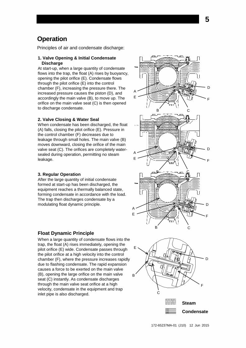
Operation Principles of air and condensate discharge:
1. Valve Opening & Initial Condensate Discharge
At start-up, when a large quantity of condensate flows into the trap, the float (A) rises by buoyancy, opening the pilot orifice (E). Condensate flows through the pilot orifice (E) into the control chamber (F), increasing the pressure there. The increased pressure causes the piston (D), and accordingly the main valve (B), to move up. The orifice on the main valve seat (C) is then opened to discharge condensate.
2. Valve Closing & Water Seal When condensate has been discharged, the float (A) falls, closing the pilot orifice (E). Pressure in the control chamber (F) decreases due to leakage through small holes. The main valve (B) moves downward, closing the orifice of the main valve seat (C). The orifices are completely water-sealed during operation, permitting no steam leakage.
3. Regular Operation After the large quantity of initial condensate formed at start-up has been discharged, the equipment reaches a thermally balanced state, forming condensate in accordance with the load. The trap then discharges condensate by a modulating float dynamic principle.
Float Dynamic Principle When a large quantity of condensate flows into the trap, the float (A) rises immediately, opening the pilot orifice (E) wide. Condensate passes through the pilot orifice at a high velocity into the control chamber (F), where the pressure increases rapidly due to flashing condensate. The rapid expansion causes a force to be exerted on the main valve (B), opening the large orifice on the main valve seat (C) instantly. As condensate discharges through the main valve seat orifice at a high velocity, condensate in the equipment and trap inlet pipe is also discharged.
Steam
Condensate
A E
B C
D
F
A E
B C
D
F
A E
B C
D
F
E
B
C
F
D
172-65237MA-01 (J10) 12 Jun 2015
6
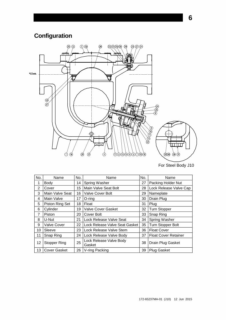
Configuration
For Steel Body J10
No. Name No. Name No. Name 1 Body 14 Spring Washer 27 Packing Holder Nut 2 Cover 15 Main Valve Seat Bolt 28 Lock Release Valve Cap 3 Main Valve Seat 16 Valve Cover Bolt 29 Nameplate 4 Main Valve 17 O-ring 30 Drain Plug 5 Piston Ring Set 18 Float 31 Plug 6 Cylinder 19 Valve Cover Gasket 32 Turn Stopper 7 Piston 20 Cover Bolt 33 Snap Ring 8 U-Nut 21 Lock Release Valve Seat 34 Spring Washer 9 Valve Cover 22 Lock Release Valve Seat Gasket 35 Turn Stopper Bolt 10 Sleeve 23 Lock Release Valve Stem 36 Float Cover 11 Snap Ring 24 Lock Release Valve Body 37 Float Cover Retainer
12 Stopper Ring 25 Lock Release Valve Body Gasket 38 Drain Plug Gasket
13 Cover Gasket 26 V-ring Packing 39 Plug Gasket
172-65237MA-01 (J10) 12 Jun 2015
7
Installation
Install properly and DO NOT use this product outside the recommended operating pressure, temperature and other specification ranges. Improper use may result in such hazards as damage to the product or malfunctions which may lead to serious accidents. Local regulations may restrict the use of this product to below the conditions quoted.
CAUTION
Use hoisting equipment for heavy objects (weighing approximately 20 kg (44 lb) or more). Failure to do so may result in back strain or other injury if the object should fall.
CAUTION
Take measures to prevent people from coming into direct contact with product outlets. Failure to do so may result in burns or other injury from the discharge of fluids.
CAUTION
Installation, inspection, maintenance, repairs, disassembly, adjustment and valve opening/closing should be carried out only by trained maintenance personnel. 1. Before installation, be sure to remove all protective seals. 2. Install inlet and outlet valves to isolate the trap and a bypass valve to discharge
condensate from equipment and piping in the event of trap failure and when performing maintenance.
3. Before installing the product, open the inlet valve and blow out the piping to remove any piping scraps, dirt and oil. Close the inlet valve after blowdown.
4. Make sure the inlet and outlet valves are closed before beginning installation. 5. Install a strainer (40 mesh or finer) at the inlet side of the product. The strainer
should be installed horizontally with the basket horizontal to the piping. 6. Install the product into the piping in a manner that allows condensate flow
naturally down into the trap, with the arrow on the product body pointing in the direction of condensate flow.
7. The trap should be inclined no more than 5° horizontally and front-to-back. 8. When the trap is operating (when the main valve is opening and closing), the
discharging condensate may cause shocks or recoil, so make sure that the piping before and after the trap is securely supported.
9. Secure sufficient space for inspection and maintenance.
If there is a problem, determine the cause using the “Troubleshooting” section in this manual.
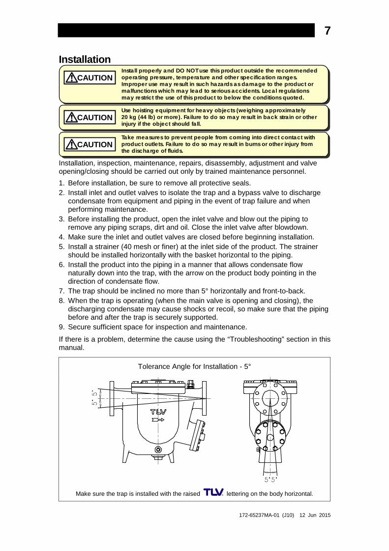
Tolerance Angle for Installation - 5°
Make sure the trap is installed with the raised lettering on the body horizontal.

172-65237MA-01 (J10) 12 Jun 2015
8
Operation
Installation, inspection, maintenance, repairs, disassembly, adjustment and valve opening/closing should be carried out only by trained maintenance personnel.
1. For Start-up Operation (1) Just after the trap is installed or when it has been idle for a long period of time, be
sure to blow out the rust and scale from the inside of the piping before opening the trap inlet valve.
(2) After opening the outlet valve, slowly open the inlet valve, being very careful not to open it too suddenly. When this is done, the steam trap will begin operation automatically. It will shortly stabilize into normal operation. If air binding or steam-locking occurs, or to more rapidly vent large quantities of initial air in the piping, use the lock release valve (see “Lock Release Valve Operation” below).
(3) Reconfirm the status of the trap operation (see the “Operational Check” section). If status is normal and stable, continue use with the valve open as it is.
(4) When the trap will not be used for long periods of time, be sure to discharge any residual condensate to prevent the pipes from rusting.
2. Corrective Measures When a Malfunction Occurs (1) In the event of an abnormality, first carry out the following: a) Close the inlet valve and outlet valves. b) Open the bypass valve and discharge the condensate from the equipment and
pipes using the bypass. (2) Let the trap body cool thoroughly and, being careful of residual pressure and hot
condensate, take the appropriate corrective measures in line with the remedial procedures described in the troubleshooting section.
Lock Release Valve Operation
Be sure to use only the recommended components when repairing the product, and NEVER attempt to modify the product in any way. Failure to observe these precautions may result in damage to the product or burns or other injury due to malfunction or the discharge of fluids.
CAUTION
Installation, inspection, maintenance, repairs, disassembly, and adjustment should be done only by trained maintenance personnel.
To operate the lock release valve: 1. Remove the lock release valve cap with a 27 mm
(11∕16”) wrench. 2. Using a 10 mm (⅜”) wrench, turn the lock release
valve stem counter-clockwise. 3. With an appropriate number of turns air binding
or steam-locking will cease and the trap will function normally. If necessary, increase the degree of valve opening further.
4. After having checked that the trap continues working normally, close the lock release valve by turning the stem clockwise, and reinstall the cap (tighten to a torque of 15 N⋅m (11 ft⋅lb)).
CAUTION Do not leave the lock release valve open during regular operation. Always be sure to close the lock release valve after eliminating air binding or steam-locking.
Cap
Stem
Valve Seat
172-65237MA-01 (J10) 12 Jun 2015
9
Maintenance
Take measures to prevent people from coming into direct contact with product outlets. Failure to do so may result in burns or other injury from the discharge of fluids.
CAUTION
Be sure to use only the recommended components when repairing the product, and NEVER attempt to modify the product in any way. Failure to observe these precautions may result in damage to the product or burns or other injury due to malfunction or the discharge of fluids.
CAUTION
Operational Check A visual inspection of the following items should be done on a daily basis to determine whether the trap is operating properly or has failed. Periodically (at least biannually) the sound of operation and the trap surface temperature should also be checked by using diagnostic equipment, such as a stethoscope or thermometer. A complete disassembly and inspection should be performed at least once every 3 years.
If the trap should fail, it may cause damage to piping and equipment, resulting in faulty or low quality products or losses due to steam leakage.
Normal : Condensate is discharged intermittently and there is no leakage when the valve is closed. After the sound of the flow of condensate continues for some time, the sound of the valve closing on the valve seat can be heard. This is followed by an interval in which the trap makes no sound, after which the cycle is again repeated.
Blocked (Discharge Impossible)
: No condensate is discharged. The trap is quiet and makes no noise, and the surface temperature of the trap is low.
Blowing : Live steam continually flows from the outlet and there is a continuous metallic sound.
Steam Leakage : Live steam is discharged through the trap outlet together with condensate, accompanied by a high-pitched sound.
Flash Steam Live Steam Leakage
Parts Inspection When parts have been removed, or during periodic inspections, use the following table to inspect the parts and replace any that are found to be defective.
Procedure Gaskets, O-rings: Check for warping or damage Sleeve: Check for wear Main Valve Seat (shaft): Check for dirt, oil film, wear or damage Main Valve, Main Valve Seat: Check for build-up or wear on seating surfaces Piston Ring Set: Check for wear, warping or damage Float: Check for deformation, scratches or dents Body Interior: Check for the build-up of scale V-ring Packing: Check for warping or damage Lock Release Valve Stem: Check for build-up or wear on seating surfaces Lock Release Valve Seat: Check for build-up, damage or wear
Clear, slightly bluish jet
White jet containing
water droplets

172-65237MA-01 (J10) 12 Jun 2015
10
Disassembly / Reassembly
NEVER apply direct heat to the float. The float may explode due to increased internal pressure, causing accidents leading to serious injury or damage to property and equipment.
WARNING
Use hoisting equipment for heavy objects (weighing approximately 20 kg (44 lb) or more). Failure to do so may result in back strain or other injury if the object should fall.
CAUTION
When disassembling or removing the product, wait until the internal pressure equals atmospheric pressure and the surface of the product has cooled to room temperature. Disassembling or removing the product when it is hot or under pressure may lead to discharge of fluids, causing burns, other injuries or damage.
CAUTION
Use the following procedures to remove components. Use the same procedures in reverse to reassemble. (Installation, inspection, maintenance, repairs, disassembly, adjustment and valve opening/closing should be carried out only by trained maintenance personnel.)
Disassembly / Reassembly of General Components
Part During Disassembly During Reassembly Drain Plug (cast iron body)
Remove with a wrench and drain remaining condensate
Wrap 3 – 3.5 turns of sealing tape around the threads or coat with sealing compound and tighten to the proper torque
Drain Plug (steel body)
Remove with a wrench and drain remaining condensate
Coat threads with anti-seize; consult the table of tightening torques and tighten to the proper torque
Drain Plug Gasket (steel body)
Remove the gasket and clean sealing surfaces
Replace with a new gasket; coat surfaces with anti-seize
Cover Bolt Remove with a socket wrench
Coat threads with anti-seize; tighten evenly, being careful not to tighten one side more than the other; consult the table of tightening torques and tighten to the proper torque
Cover Remove the cover Align the arrows on cover and body, then reattach Cover Gasket Remove the gasket
and clean sealing surfaces
Replace with a new gasket; make sure there are no pieces of the old gasket left on the sealing surfaces of the body or cover
Snap Ring Remove with appropriate pliers
Insert securely into its groove
Float Cover Retainer
Lift up and out Place the retainer in the body on top of the float cover
Float Cover Lift up and out Place on the ledge inside the body, making sure the rounded side is on top
Float
Remove, being careful not to scratch the polished surface
Insert, being careful not to scratch or misshape
172-65237MA-01 (J10) 12 Jun 2015
11
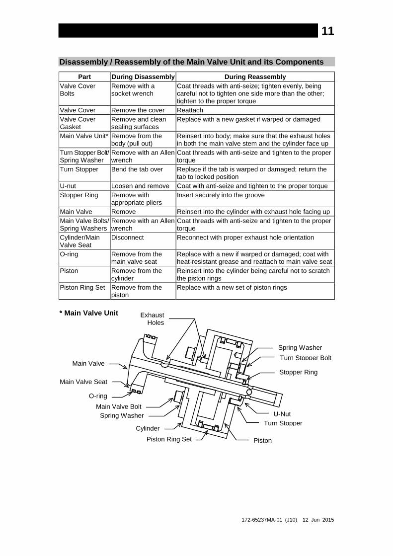
Disassembly / Reassembly of the Main Valve Unit and its Components
Part During Disassembly During Reassembly Valve Cover Bolts
Remove with a socket wrench
Coat threads with anti-seize; tighten evenly, being careful not to tighten one side more than the other; tighten to the proper torque
Valve Cover Remove the cover Reattach Valve Cover Gasket
Remove and clean sealing surfaces
Replace with a new gasket if warped or damaged
Main Valve Unit* Remove from the body (pull out)
Reinsert into body; make sure that the exhaust holes in both the main valve stem and the cylinder face up
Turn Stopper Bolt/ Spring Washer
Remove with an Allen wrench
Coat threads with anti-seize and tighten to the proper torque
Turn Stopper Bend the tab over Replace if the tab is warped or damaged; return the tab to locked position
U-nut Loosen and remove Coat with anti-seize and tighten to the proper torque Stopper Ring Remove with
appropriate pliers Insert securely into the groove
Main Valve Remove Reinsert into the cylinder with exhaust hole facing up Main Valve Bolts/ Spring Washers
Remove with an Allen wrench
Coat threads with anti-seize and tighten to the proper torque
Cylinder/Main Valve Seat
Disconnect Reconnect with proper exhaust hole orientation
O-ring Remove from the main valve seat
Replace with a new if warped or damaged; coat with heat-resistant grease and reattach to main valve seat
Piston Remove from the cylinder
Reinsert into the cylinder being careful not to scratch the piston rings
Piston Ring Set Remove from the piston
Replace with a new set of piston rings
* Main Valve Unit
Main Valve Seat
Cylinder
Piston
U-Nut
Exhaust Holes
Turn Stopper
Piston Ring Set
O-ring Main Valve Bolt
Spring Washer
Main Valve Turn Stopper Bolt Spring Washer
Stopper Ring
172-65237MA-01 (J10) 12 Jun 2015
12
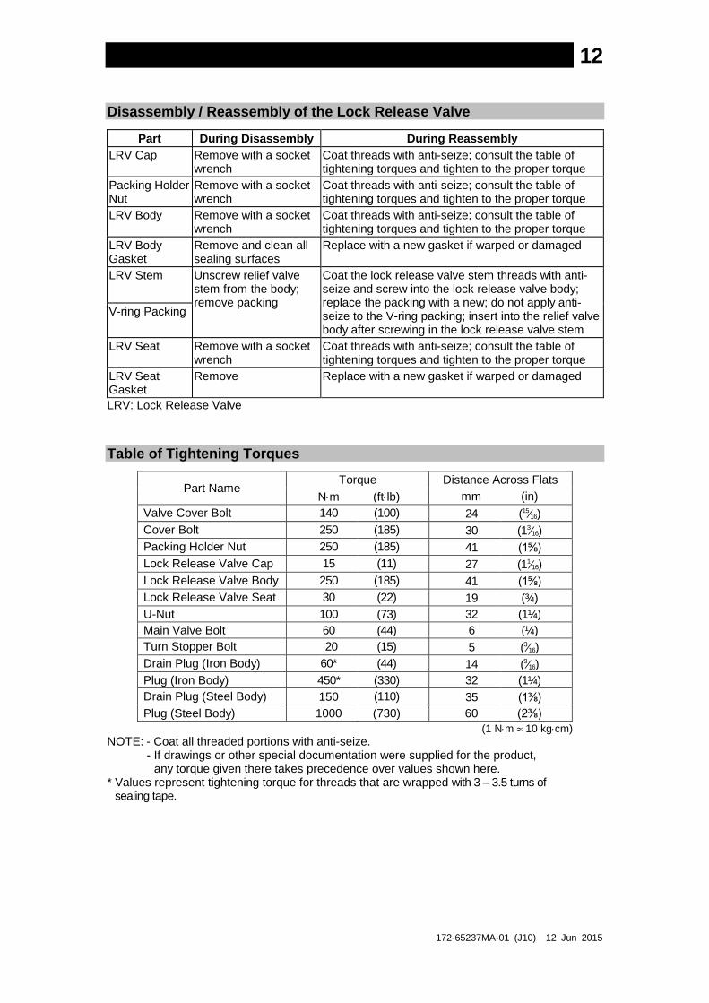
Disassembly / Reassembly of the Lock Release Valve
Part During Disassembly During Reassembly LRV Cap Remove with a socket
wrench Coat threads with anti-seize; consult the table of tightening torques and tighten to the proper torque
Packing Holder Nut
Remove with a socket wrench
Coat threads with anti-seize; consult the table of tightening torques and tighten to the proper torque
LRV Body Remove with a socket wrench
Coat threads with anti-seize; consult the table of tightening torques and tighten to the proper torque
LRV Body Gasket
Remove and clean all sealing surfaces
Replace with a new gasket if warped or damaged
LRV Stem Unscrew relief valve stem from the body; remove packing
Coat the lock release valve stem threads with anti-seize and screw into the lock release valve body; replace the packing with a new; do not apply anti-seize to the V-ring packing; insert into the relief valve body after screwing in the lock release valve stem
V-ring Packing
LRV Seat Remove with a socket wrench
Coat threads with anti-seize; consult the table of tightening torques and tighten to the proper torque
LRV Seat Gasket
Remove Replace with a new gasket if warped or damaged
LRV: Lock Release Valve
Table of Tightening Torques
Part Name Torque Distance Across Flats
N⋅m (ft⋅lb) mm (in) Valve Cover Bolt 140 (100) 24 (15∕16) Cover Bolt 250 (185) 30 (13∕16) Packing Holder Nut 250 (185) 41 (1⅝) Lock Release Valve Cap 15 (11) 27 (11∕16) Lock Release Valve Body 250 (185) 41 (1⅝) Lock Release Valve Seat 30 (22) 19 (¾) U-Nut 100 (73) 32 (1¼) Main Valve Bolt 60 (44) 6 (¼) Turn Stopper Bolt 20 (15) 5 (3∕16) Drain Plug (Iron Body) 60* (44) 14 (9∕16) Plug (Iron Body) 450* (330) 32 (1¼) Drain Plug (Steel Body) 150 (110) 35 (1⅜) Plug (Steel Body) 1000 (730) 60 (2⅜)
(1 N⋅m ≈ 10 kg⋅cm) NOTE: - Coat all threaded portions with anti-seize.
- If drawings or other special documentation were supplied for the product, any torque given there takes precedence over values shown here.
* Values represent tightening torque for threads that are wrapped with 3 – 3.5 turns of sealing tape.
172-65237MA-01 (J10) 12 Jun 2015
13
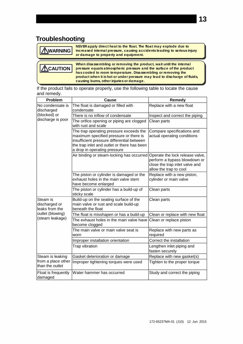
Troubleshooting
NEVER apply direct heat to the float. The float may explode due to increased internal pressure, causing accidents leading to serious injury or damage to property and equipment.
WARNING
When disassembling or removing the product, wait until the internal pressure equals atmospheric pressure and the surface of the product has cooled to room temperature. Disassembling or removing the product when it is hot or under pressure may lead to discharge of fluids, causing burns, other injuries or damage.
CAUTION
If the product fails to operate properly, use the following table to locate the cause and remedy.
Problem Cause Remedy No condensate is discharged (blocked) or discharge is poor
The float is damaged or filled with condensate
Replace with a new float
There is no inflow of condensate Inspect and correct the piping The orifice opening or piping are clogged with rust and scale
Clean parts
The trap operating pressure exceeds the maximum specified pressure or there is insufficient pressure differential between the trap inlet and outlet or there has been a drop in operating pressure
Compare specifications and actual operating conditions
Air binding or steam-locking has occurred Operate the lock release valve, perform a bypass blowdown or close the trap inlet valve and allow the trap to cool
The piston or cylinder is damaged or the exhaust holes in the main valve stem have become enlarged
Replace with a new piston, cylinder or main valve
The piston or cylinder has a build-up of sticky scale
Clean parts
Steam is discharged or leaks from the outlet (blowing) (steam leakage)
Build-up on the seating surface of the main valve or rust and scale build-up beneath the float
Clean parts
The float is misshapen or has a build-up Clean or replace with new float The exhaust holes in the main valve have become clogged
Clean or replace piston
The main valve or main valve seat is worn
Replace with new parts as required
Improper installation orientation Correct the installation Trap vibration Lengthen inlet piping and
fasten securely Steam is leaking from a place other than the outlet
Gasket deterioration or damage Replace with new gasket(s) Improper tightening torques were used Tighten to the proper torque
Float is frequently damaged
Water hammer has occurred Study and correct the piping

172-65237MA-01 (J10) 12 Jun 2015
14
Product Warranty 1. Warranty Period
One year following product delivery. 2. Warranty Coverage
TLV CO., LTD. warrants this product to the original purchaser to be free from defective materials and workmanship. Under this warranty, the product will be repaired or replaced at our option, without charge for parts or labor.
3. This product warranty will not apply to cosmetic defects, nor to any product
whose exterior has been damaged or defaced; nor does it apply in the following cases:
1) Malfunctions due to improper installation, use, handling, etc., by other than TLV CO., LTD. authorized service representatives.
2) Malfunctions due to dirt, scale, rust, etc.
3) Malfunctions due to improper disassembly and reassembly, or inadequate inspection and maintenance by other than TLV CO., LTD. authorized service representatives.
4) Malfunctions due to disasters or forces of nature.
5) Accidents or malfunctions due to any other cause beyond the control of TLV CO., LTD.
4. Under no circumstances will TLV CO., LTD. be liable for consequential
economic loss damage or consequential damage to property.
* * * * * * *
For Service or Technical Assistance:
Contact your representative or your regional office.
Manufacturer
CO., LTD. 881 Nagasuna, Noguchi Kakogawa, Hyogo 675-8511 JAPAN Tel: 81-(0)79 - 427 - 1800