Embed Size (px)
Citation preview
All
right
s re
serv
ed. P
assi
ng o
n an
d co
pyin
g of
this
docu
men
t, us
e an
d co
mm
unic
atio
n of
its
cont
ents
not p
erm
itted
with
out w
ritte
n au
thor
izat
ion
from
Alc
atel
.
ED
1AA
000
14 0
004
(900
7) A
4 –
ALI
CE
04.
10
Y 1
04
957.130.132 TQZZA
RELEASED
/3AL 78991 AAAA TQZZA
4
4
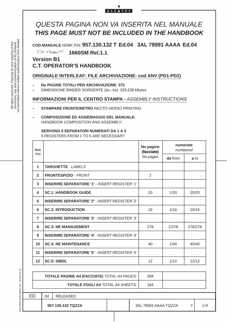
QUESTA PAGINA NON VA INSERITA NEL MANUALETHIS PAGE MUST NOT BE INCLUDED IN THE HANDBOOK
COD.MANUALE HDBK P/N: 957.130.132 T Ed.04 3AL 78991 AAAA Ed.04
1660SM Rel.1.1Version B1C.T. OPERATOR’S HANDBOOK
ORIGINALE INTERLEAF: FILE ARCHIVIAZIONE: cod ANV (PD1-PD2)
– No PAGINE TOTALI PER ARCHIVIAZIONE: 372– DIMENSIONE BINDER SORGENTE (du –ks): 329.238 kBytes
INFORMAZIONI PER IL CENTRO STAMPA - ASSEMBLY INSTRUCTIONS
– STAMPARE FRONTE/RETRO RECTO-VERSO PRINTING
– COMPOSIZIONE ED ASSIEMAGGIO DEL MANUALE:HANDBOOK COMPOSITION AND ASSEMBLY:
SERVONO 5 SEPARATORI NUMERATI DA 1 A 55 REGISTERS FROM 1 TO 5 ARE NECESSARY
faseNo pagine(facciate)
numeratenumbered
step (facciate)No pages da from a to
1 TARGHETTE - LABELS
2 FRONTESPIZIO - FRONT 2
3 INSERIRE SEPARATORE ’1’ - INSERT REGISTER ’1’
4 SC.1: HANDBOOK GUIDE 20 1/20 20/20
5 INSERIRE SEPARATORE ’2’ - INSERT REGISTER ’2’
6 SC.2: INTRODUCTION 16 1/16 16/16
7 INSERIRE SEPARATORE ’3’ - INSERT REGISTER ’3’
8 SC.3: NE MANAGEMENT 278 1/278 278/278
9 INSERIRE SEPARATORE ’4’ - INSERT REGISTER ’4’
10 SC.4: NE MAINTENANCE 40 1/40 40/40
11 INSERIRE SEPARATORE ’5’ - INSERT REGISTER ’5’
12 SC.5: SIBDL 12 1/12 12/12
TOTALE PAGINE A4 (FACCIATE) TOTAL A4 PAGES: 368
TOTALE FOGLI A4 TOTAL A4 SHEETS: 184
All
right
s re
serv
ed. P
assi
ng o
n an
d co
pyin
g of
this
docu
men
t, us
e an
d co
mm
unic
atio
n of
its
cont
ents
not p
erm
itted
with
out w
ritte
n au
thor
izat
ion
from
Alc
atel
.
ED
1AA
000
14 0
004
(900
7) A
4 –
ALI
CE
04.
10
Y 2
04
957.130.132 TQZZA
RELEASED
/3AL 78991 AAAA TQZZA
4
4
QUESTA PAGINA NON VA INSERITA NEL MANUALETHIS PAGE MUST NOT BE INCLUDED IN THE HANDBOOK
ALCATEL OPTICS GROUPSite
Originators
VIMERCATE
:
Domain
1660SM REL.1.1
Division
VERSION B1
Rubric
C.T. OPERATOR’S HANDBOOK
TypeDistribution Codes Internal External
::::
TNDOPTINEX1660SM1660SM REL.1.1 C.T. OPERATOR’S HANDBOOK
:
P. GHELFI
Approvals
NameApp.
App.Name
S. MAGGIO
C. FAVERO
WARNING FOR A-UNITS OTHER THAN A-ITALY
• Labels are done according to A-Italy binder format.• Source files: ALICE 6.10
957.130.132 T3AL 78991 AAAAEd.04
1660SM Rel.1.1
Version B1STM 16 Multiservice Metro Node
C.T. OPERATOR’S HANDBOOK
All
right
s re
serv
ed. P
assi
ng o
n an
d co
pyin
g of
this
docu
men
t, us
e an
d co
mm
unic
atio
n of
its
cont
ents
not p
erm
itted
with
out w
ritte
n au
thor
izat
ion
from
Alc
atel
.
ED
1AA
000
14 0
004
(900
7) A
4 –
ALI
CE
04.
10
Y 3
04
957.130.132 TQZZA
RELEASED
/3AL 78991 AAAA TQZZA
4
4
1660SM Rel.1.1
Version B1
STM 16 Multiservice Metro Node
C.T. OPERATOR’S HANDBOOK
957.130.132 T Ed.04 3AL 78991 AAAA Ed.04
VOL.1/1
1660SM Rel.1.1Version B1
STM 16 Multiservice Metro Node
C.T. OPERATOR’S HANDBOOK
957.130.132 T Ed.04 3AL 78991 AAAA Ed.04
VOL.1/1
1660SM Rel.1.1Version B1
STM 16 Multiservice Metro Node
957.130.132 T Ed.04 3AL 78991 AAAA Ed.04 C.T. OPERATOR’S HANDBOOK VOL.1/1
1660SM Rel.1.1Version B1
STM 16 Multiservice Metro Node957.130.132 T Ed.04 3AL 78991 AAAA Ed.04 C.T. OPERATOR’S HANDBOOK VOL.1/1
1660SM Rel.1.1Version B1
STM 16 Multiservice Metro Node
957.130.132 T Ed.04 3AL 78991 AAAA Ed.04 C.T. OPERATOR’S HANDBOOK VOL.1/1

All
right
s re
serv
ed. P
assi
ng o
n an
d co
pyin
g of
this
docu
men
t, us
e an
d co
mm
unic
atio
n of
its
cont
ents
not p
erm
itted
with
out w
ritte
n au
thor
izat
ion
from
Alc
atel
.
ED
1AA
000
14 0
004
(900
7) A
4 –
ALI
CE
04.
10
Y 4
04
957.130.132 TQZZA
RELEASED
/3AL 78991 AAAA TQZZA
4
4
FINE DEL DOCUMENTO INTERNO – END OF INTERNAL DOCUMENT
957.130.132 T Ed.04 3AL 78991 AAAA Ed.04
Craft Terminal Operator’s Handbook
AlcatelTM 1660SM
STM 16 Multiservice Metro Node
1660SM Rel.1.1
Version B1

957.130.132 T Ed.04 3AL 78991 AAAA Ed.04
All
right
s re
serv
ed. P
assi
ng o
n an
d co
pyin
g of
this
docu
men
t, us
e an
d co
mm
unic
atio
n of
its
cont
ents
not p
erm
itted
with
out w
ritte
n au
thor
izat
ion
from
Alc
atel
.
ED
1AA
000
14 0
004
(900
7) A
4 –
ALI
CE
04.
10
1
04
957.130.132 T
SC.1:HANDBOOK GUIDE
/3AL 78991 AA AA
20
20
1660SM REL.1.1 C.T. OPERATOR’S HANDBOOK
TABLE OF CONTENTS
LIST OF FIGURES AND TABLES 2. . . . . . . . . . . . . . . . . . . . . . . . . . . . . . . . . . . . . . . . . . . . . . . . . . . . . . .
1 HANDBOOK STRUCTURE AND CONFIGURATION CHECK 3. . . . . . . . . . . . . . . . . . . . . . . . . . . . 1.1 General information 3. . . . . . . . . . . . . . . . . . . . . . . . . . . . . . . . . . . . . . . . . . . . . . . . . . . . . . . . . . . . 1.2 Handbook applicability 3. . . . . . . . . . . . . . . . . . . . . . . . . . . . . . . . . . . . . . . . . . . . . . . . . . . . . . . . . 1.3 Purpose of the handbook 4. . . . . . . . . . . . . . . . . . . . . . . . . . . . . . . . . . . . . . . . . . . . . . . . . . . . . . . 1.4 Handbook configuration check 5. . . . . . . . . . . . . . . . . . . . . . . . . . . . . . . . . . . . . . . . . . . . . . . . .
1.4.1 Notes on Ed.01 5. . . . . . . . . . . . . . . . . . . . . . . . . . . . . . . . . . . . . . . . . . . . . . . . . . . . . . . . . . . . . 1.4.2 Notes on Ed.02–proposal 5. . . . . . . . . . . . . . . . . . . . . . . . . . . . . . . . . . . . . . . . . . . . . . . . . . . . 1.4.3 Notes on Ed.02A 5. . . . . . . . . . . . . . . . . . . . . . . . . . . . . . . . . . . . . . . . . . . . . . . . . . . . . . . . . . . . 1.4.4 Notes on Ed.03 6. . . . . . . . . . . . . . . . . . . . . . . . . . . . . . . . . . . . . . . . . . . . . . . . . . . . . . . . . . . . . 1.4.5 Notes on Ed.04 6. . . . . . . . . . . . . . . . . . . . . . . . . . . . . . . . . . . . . . . . . . . . . . . . . . . . . . . . . . . . .
2 PRODUCT-RELEASE HANDBOOKS 7. . . . . . . . . . . . . . . . . . . . . . . . . . . . . . . . . . . . . . . . . . . . . . . . .
3 SAFETY NORMS AND LABELS 11. . . . . . . . . . . . . . . . . . . . . . . . . . . . . . . . . . . . . . . . . . . . . . . . . . . . . 3.1 First aid for electric shock 11. . . . . . . . . . . . . . . . . . . . . . . . . . . . . . . . . . . . . . . . . . . . . . . . . . . . . . 3.2 Norms and labels 13. . . . . . . . . . . . . . . . . . . . . . . . . . . . . . . . . . . . . . . . . . . . . . . . . . . . . . . . . . . . . .
4 HANDBOOK DESCRIPTION 15. . . . . . . . . . . . . . . . . . . . . . . . . . . . . . . . . . . . . . . . . . . . . . . . . . . . . . . . .
5 GENERAL ON ALCATEL CUSTOMER DOCUMENTATION 17. . . . . . . . . . . . . . . . . . . . . . . . . . . . . . 5.1 Products, product-releases, versions and Customer Documentation 17. . . . . . . . . . . . . . 5.2 Handbook supply to Customers 17. . . . . . . . . . . . . . . . . . . . . . . . . . . . . . . . . . . . . . . . . . . . . . . . . 5.3 Aims of standard Customer Documentation 17. . . . . . . . . . . . . . . . . . . . . . . . . . . . . . . . . . . . . 5.4 Handbook Updating 18. . . . . . . . . . . . . . . . . . . . . . . . . . . . . . . . . . . . . . . . . . . . . . . . . . . . . . . . . . . .
5.4.1 Changes introduced in the same product-release (same handbook P/N) 18. . . . . . . . . . . . 5.4.2 Supplying updated handbooks to Customers 18. . . . . . . . . . . . . . . . . . . . . . . . . . . . . . . . . . . 5.4.3 Changes due to a new product-release 18. . . . . . . . . . . . . . . . . . . . . . . . . . . . . . . . . . . . . . . .
5.5 Customer documentation supply on CD–ROM 19. . . . . . . . . . . . . . . . . . . . . . . . . . . . . . . . . . . 5.5.1 Contents, creation and production of a CD–ROM 19. . . . . . . . . . . . . . . . . . . . . . . . . . . . . . . . 5.5.2 Use of the CD–ROM 20. . . . . . . . . . . . . . . . . . . . . . . . . . . . . . . . . . . . . . . . . . . . . . . . . . . . . . . . . 5.5.3 CD–ROM identification 20. . . . . . . . . . . . . . . . . . . . . . . . . . . . . . . . . . . . . . . . . . . . . . . . . . . . . . . 5.5.4 CD–ROM updating 20. . . . . . . . . . . . . . . . . . . . . . . . . . . . . . . . . . . . . . . . . . . . . . . . . . . . . . . . . .
ED DATE CHANGE NOTE APPRAISAL AUTHORITY ORIGINATOR
01 000307 S.MAGGIO ITAVE P.GHELFI ITAVE
03 001023 SC00101902 S.MAGGIO ITAVE P.GHELFI ITAVE
00112404 SC00111702 S.MAGGIO ITAVE P.GHELFI ITAVE
1660SM REL.1.1Version B1C.T. OPERATOR’S HANDBOOK
E.CORRADINI
E.CORRADINI
C. FAVERO
All
right
s re
serv
ed. P
assi
ng o
n an
d co
pyin
g of
this
docu
men
t, us
e an
d co
mm
unic
atio
n of
its
cont
ents
not p
erm
itted
with
out w
ritte
n au
thor
izat
ion
from
Alc
atel
.
ED
1AA
000
14 0
004
(900
7) A
4 –
ALI
CE
04.
10
2
04
957.130.132 T
SC.1:HANDBOOK GUIDE
/3AL 78991 AA AA
20
20
LIST OF FIGURES AND TABLES
Table 1. Handbooks related to the specific product hardware 7. . . . . . . . . . . . . . . . . . . . . . . . . . . . . . . . Table 2. Handbooks related to the specific product software management and local productcontrol 7. . . . . . . . . . . . . . . . . . . . . . . . . . . . . . . . . . . . . . . . . . . . . . . . . . . . . . . . . . . . . . . . . . . . . . . . . . . . . . . Table 3. Handbooks common to Alcatel Network Elements using 1320CT Rel. 1.x platform 8. . . . . Table 4. Documentation on CD–ROM 8. . . . . . . . . . . . . . . . . . . . . . . . . . . . . . . . . . . . . . . . . . . . . . . . . . . . Table 5. Optional handbook common to 1660SM and 1650SMC 9. . . . . . . . . . . . . . . . . . . . . . . . . . . . .
All
right
s re
serv
ed. P
assi
ng o
n an
d co
pyin
g of
this
docu
men
t, us
e an
d co
mm
unic
atio
n of
its
cont
ents
not p
erm
itted
with
out w
ritte
n au
thor
izat
ion
from
Alc
atel
.
ED
1AA
000
14 0
004
(900
7) A
4 –
ALI
CE
04.
10
3
04
957.130.132 T
SC.1:HANDBOOK GUIDE
/3AL 78991 AA AA
20
20
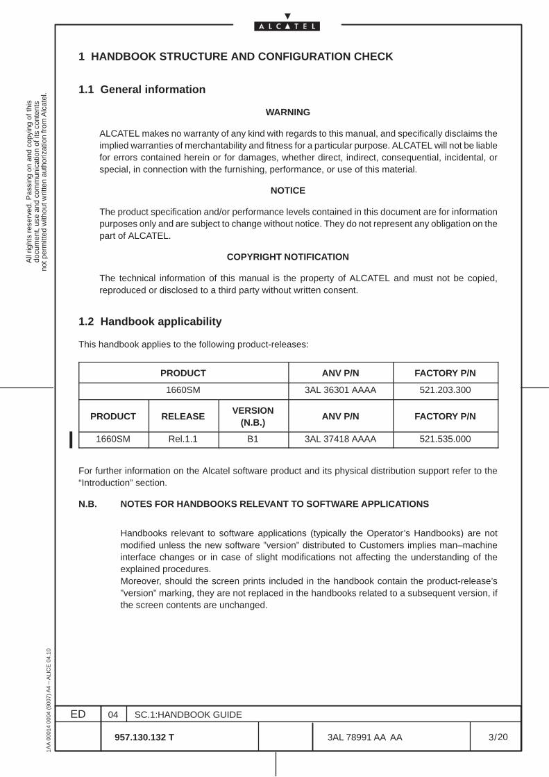
1 HANDBOOK STRUCTURE AND CONFIGURATION CHECK
1.1 General information
WARNING
ALCATEL makes no warranty of any kind with regards to this manual, and specifically disclaims theimplied warranties of merchantability and fitness for a particular purpose. ALCATEL will not be liablefor errors contained herein or for damages, whether direct, indirect, consequential, incidental, orspecial, in connection with the furnishing, performance, or use of this material.
NOTICE
The product specification and/or performance levels contained in this document are for informationpurposes only and are subject to change without notice. They do not represent any obligation on thepart of ALCATEL.
COPYRIGHT NOTIFICATION
The technical information of this manual is the property of ALCATEL and must not be copied,reproduced or disclosed to a third party without written consent.
1.2 Handbook applicability
This handbook applies to the following product-releases:
PRODUCT ANV P/N FACTORY P/N
1660SM 3AL 36301 AAAA 521.203.300
PRODUCT RELEASEVERSION
(N.B.)ANV P/N FACTORY P/N
1660SM Rel.1.1 B1 3AL 37418 AAAA 521.535.000
For further information on the Alcatel software product and its physical distribution support refer to the“Introduction” section.
N.B. NOTES FOR HANDBOOKS RELEVANT TO SOFTWARE APPLICATIONS
Handbooks relevant to software applications (typically the Operator’s Handbooks) are notmodified unless the new software ”version” distributed to Customers implies man–machineinterface changes or in case of slight modifications not affecting the understanding of theexplained procedures.Moreover, should the screen prints included in the handbook contain the product-release’s”version” marking, they are not replaced in the handbooks related to a subsequent version, ifthe screen contents are unchanged.
All
right
s re
serv
ed. P
assi
ng o
n an
d co
pyin
g of
this
docu
men
t, us
e an
d co
mm
unic
atio
n of
its
cont
ents
not p
erm
itted
with
out w
ritte
n au
thor
izat
ion
from
Alc
atel
.
ED
1AA
000
14 0
004
(900
7) A
4 –
ALI
CE
04.
10
4
04
957.130.132 T
SC.1:HANDBOOK GUIDE
/3AL 78991 AA AA
20
20
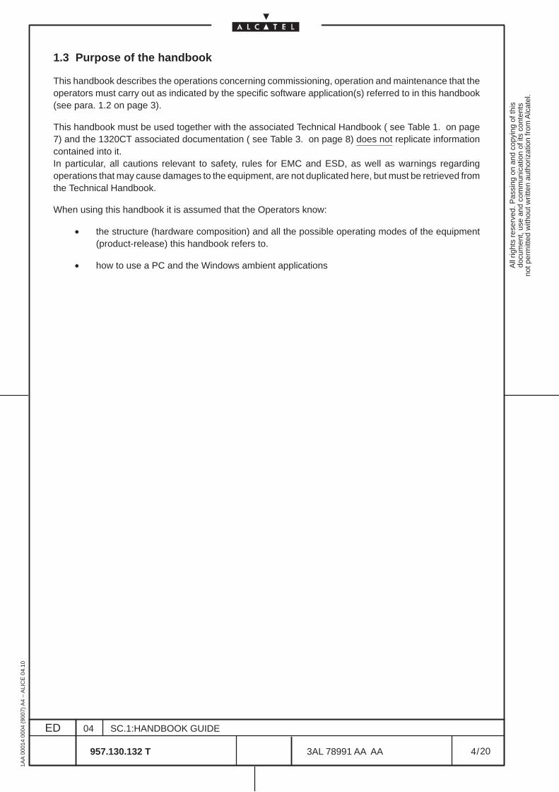
1.3 Purpose of the handbook
This handbook describes the operations concerning commissioning, operation and maintenance that theoperators must carry out as indicated by the specific software application(s) referred to in this handbook(see para. 1.2 on page 3).
This handbook must be used together with the associated Technical Handbook ( see Table 1. on page7) and the 1320CT associated documentation ( see Table 3. on page 8) does not replicate informationcontained into it.In particular, all cautions relevant to safety, rules for EMC and ESD, as well as warnings regardingoperations that may cause damages to the equipment, are not duplicated here, but must be retrieved fromthe Technical Handbook.
When using this handbook it is assumed that the Operators know:
• the structure (hardware composition) and all the possible operating modes of the equipment(product-release) this handbook refers to.
• how to use a PC and the Windows ambient applications
All
right
s re
serv
ed. P
assi
ng o
n an
d co
pyin
g of
this
docu
men
t, us
e an
d co
mm
unic
atio
n of
its
cont
ents
not p
erm
itted
with
out w
ritte
n au
thor
izat
ion
from
Alc
atel
.
ED
1AA
000
14 0
004
(900
7) A
4 –
ALI
CE
04.
10
5
04
957.130.132 T
SC.1:HANDBOOK GUIDE
/3AL 78991 AA AA
20
20
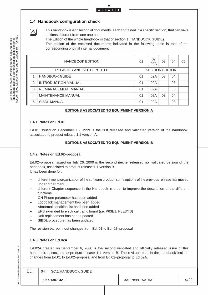
1.4 Handbook configuration check
This handbook is a collection of documents (each contained in a specific section) that can haveeditions different from one another.The Edition of the whole handbook is that of section 1 (HANDBOOK GUIDE).The edition of the enclosed documents indicated in the following table is that of thecorresponding original internal document.
HANDBOOK EDITION 0102
02A03 04 05
REGISTER AND SECTION TITLE SECTION EDITION
1 HANDBOOK GUIDE 01 02A 03 04
2 INTRODUCTION MANUAL 01 02A 03
3 NE MANAGEMENT MANUAL 01 02A 03
4 MAINTENANCE MANUAL 01 02A 03 04
5 SIBDL MANUAL 01 02A 03
EDITIONS ASSOCIATED TO EQUIPMENT VERSION A
1.4.1 Notes on Ed.01
Ed.01 issued on December 16, 1999 is the first released and validated version of the handbook,associated to product release 1.1 version A.
EDITIONS ASSOCIATED TO EQUIPMENT VERSION B
1.4.2 Notes on Ed.02–proposal
Ed.02–proposal issued on July 26, 2000 is the second neither released nor validated version of thehandbook, associated to product release 1.1 version B.It has been done for:
– different menu organization of the software product; some options of the previous release has movedunder other menu.
– different Chapter sequence in the Handbook in order to improve the description of the differentfunctions.
– OH Phone parameter has been added– Loopback management has been added– Abnormal condition list has been added– EPS extended to electrical traffic board (i.e. P63E1, P3E3/T3)– Unit replacement has been updated– SIBDL procedure has been updated
The revision bar point out changes from Ed. 01 to Ed. 02–proposal.
1.4.3 Notes on Ed.02A
Ed.02A created on September 6, 2000 is the second validated and officially released issue of thishandbook, associated to product release 1.1 Version B. The revision bars in the handbook includechanges from Ed.01 to Ed.02–proposal and from Ed.02–proposal to Ed.02A.
All
right
s re
serv
ed. P
assi
ng o
n an
d co
pyin
g of
this
docu
men
t, us
e an
d co
mm
unic
atio
n of
its
cont
ents
not p
erm
itted
with
out w
ritte
n au
thor
izat
ion
from
Alc
atel
.
ED
1AA
000
14 0
004
(900
7) A
4 –
ALI
CE
04.
10
6
04
957.130.132 T
SC.1:HANDBOOK GUIDE
/3AL 78991 AA AA
20
20
1.4.4 Notes on Ed.03
Ed.03 created on October 23, 2000 is the third validated and officially released issue of this handbook,associated to product release 1.1 Version B.
Changes with respect to Ed.02A are relevant to the addition of HW upgrading procedure from Version Ato Version B in section Maintenance.
In order to give a complete view of functionality changes of equipment’s SW from Version A to VersionB, the revision bars in the handbook include all modifications:– from Ed.01 to Ed.02–proposal– and from Ed.02–proposal to Ed.02A– and from Ed.02A to Ed.03.
EDITIONS ASSOCIATED TO EQUIPMENT VERSION B1
1.4.5 Notes on Ed.04
Ed.04 created on November 24, 2000 is the fourth validated and officially released issue of this handbook,associated to product release 1.1 Version B1.
Changes with respect to Ed.03 are relevant to the “Management States Control Panel” (CTC box has beenremoved ) and improvement of some functionality ( e.g. creation of new PM Threshold table)
The revision bars in the handbook include changes from Ed.03 to Ed.04 only.
All
right
s re
serv
ed. P
assi
ng o
n an
d co
pyin
g of
this
docu
men
t, us
e an
d co
mm
unic
atio
n of
its
cont
ents
not p
erm
itted
with
out w
ritte
n au
thor
izat
ion
from
Alc
atel
.
ED
1AA
000
14 0
004
(900
7) A
4 –
ALI
CE
04.
10
7
04
957.130.132 T
SC.1:HANDBOOK GUIDE
/3AL 78991 AA AA
20
20
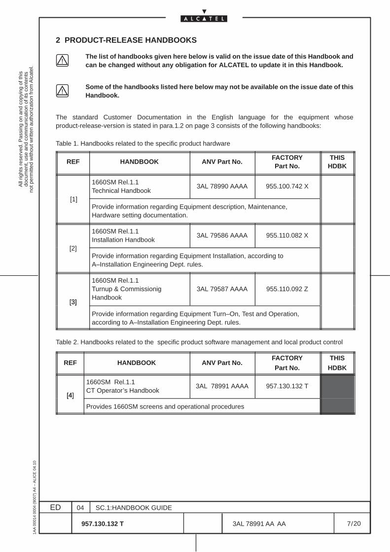
2 PRODUCT-RELEASE HANDBOOKS
The list of handbooks given here below is valid on the issue date of this Handbook andcan be changed without any obligation for ALCATEL to update it in this Handbook.
Some of the handbooks listed here below may not be available on the issue date of thisHandbook.
The standard Customer Documentation in the English language for the equipment whoseproduct-release-version is stated in para.1.2 on page 3 consists of the following handbooks:
Table 1. Handbooks related to the specific product hardware
REF HANDBOOK ANV Part No.FACTORYPart No.
THISHDBK
1660SM Rel.1.1Technical Handbook
3AL 78990 AAAA 955.100.742 X
[1]Provide information regarding Equipment description, Maintenance,Hardware setting documentation.
1660SM Rel.1.1Installation Handbook
3AL 79586 AAAA 955.110.082 X
[2]Provide information regarding Equipment Installation, according toA–Installation Engineering Dept. rules.
[3]
1660SM Rel.1.1Turnup & CommissionigHandbook
3AL 79587 AAAA 955.110.092 Z
[3]
Provide information regarding Equipment Turn–On, Test and Operation,according to A–Installation Engineering Dept. rules.
Table 2. Handbooks related to the specific product software management and local product control
REF HANDBOOK ANV Part No.FACTORY
Part No.
THIS
HDBK
[4]
1660SM Rel.1.1CT Operator’s Handbook
3AL 78991 AAAA 957.130.132 T[4]
Provides 1660SM screens and operational procedures
All
right
s re
serv
ed. P
assi
ng o
n an
d co
pyin
g of
this
docu
men
t, us
e an
d co
mm
unic
atio
n of
its
cont
ents
not p
erm
itted
with
out w
ritte
n au
thor
izat
ion
from
Alc
atel
.
ED
1AA
000
14 0
004
(900
7) A
4 –
ALI
CE
04.
10
8
04
957.130.132 T
SC.1:HANDBOOK GUIDE
/3AL 78991 AA AA
20
20
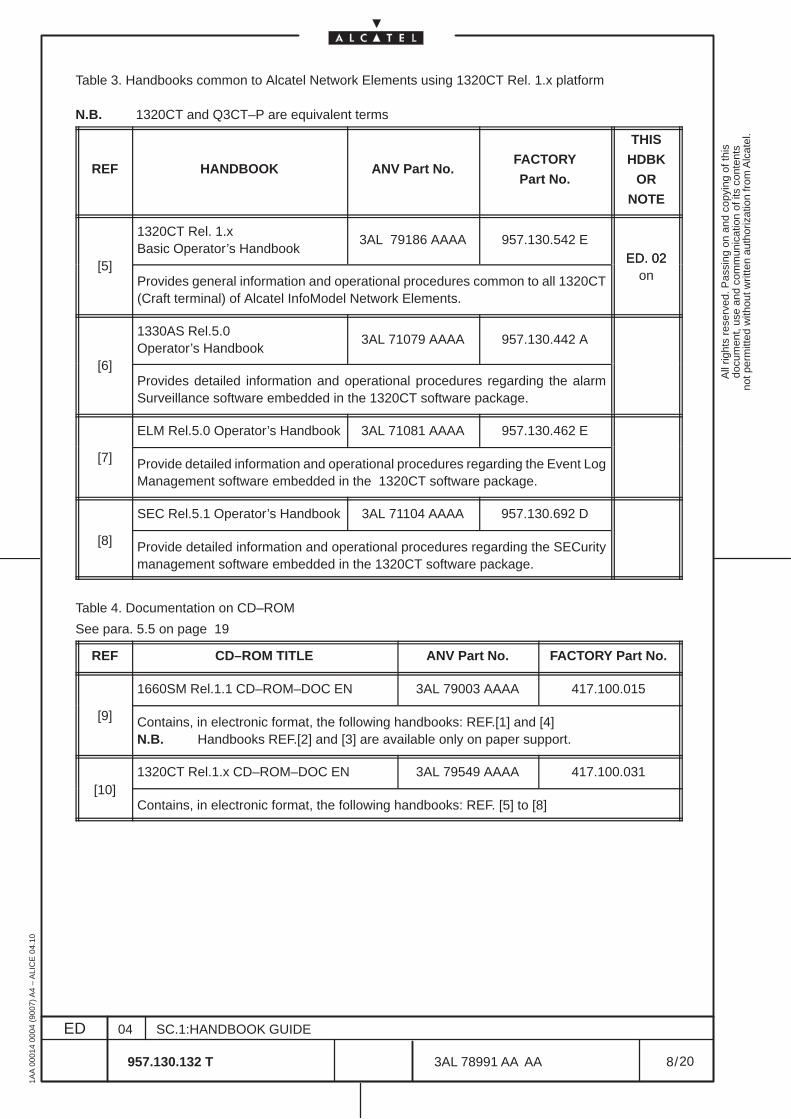
Table 3. Handbooks common to Alcatel Network Elements using 1320CT Rel. 1.x platform
N.B. 1320CT and Q3CT–P are equivalent terms
REF HANDBOOK ANV Part No.FACTORY
Part No.
THIS
HDBK
OR
NOTE
1320CT Rel. 1.xBasic Operator’s Handbook
3AL 79186 AAAA 957.130.542 EED. 02
[5]Provides general information and operational procedures common to all 1320CT(Craft terminal) of Alcatel InfoModel Network Elements.
ED. 02on
1330AS Rel.5.0Operator’s Handbook
3AL 71079 AAAA 957.130.442 A
[6]Provides detailed information and operational procedures regarding the alarmSurveillance software embedded in the 1320CT software package.
ELM Rel.5.0 Operator’s Handbook 3AL 71081 AAAA 957.130.462 E
[7] Provide detailed information and operational procedures regarding the Event LogManagement software embedded in the 1320CT software package.
SEC Rel.5.1 Operator’s Handbook 3AL 71104 AAAA 957.130.692 D
[8] Provide detailed information and operational procedures regarding the SECuritymanagement software embedded in the 1320CT software package.
Table 4. Documentation on CD–ROM
See para. 5.5 on page 19
REF CD–ROM TITLE ANV Part No. FACTORY Part No.
1660SM Rel.1.1 CD–ROM–DOC EN 3AL 79003 AAAA 417.100.015
[9] Contains, in electronic format, the following handbooks: REF.[1] and [4]N.B. Handbooks REF.[2] and [3] are available only on paper support.
1320CT Rel.1.x CD–ROM–DOC EN 3AL 79549 AAAA 417.100.031[10]
Contains, in electronic format, the following handbooks: REF. [5] to [8]
All
right
s re
serv
ed. P
assi
ng o
n an
d co
pyin
g of
this
docu
men
t, us
e an
d co
mm
unic
atio
n of
its
cont
ents
not p
erm
itted
with
out w
ritte
n au
thor
izat
ion
from
Alc
atel
.
ED
1AA
000
14 0
004
(900
7) A
4 –
ALI
CE
04.
10
9
04
957.130.132 T
SC.1:HANDBOOK GUIDE
/3AL 78991 AA AA
20
20
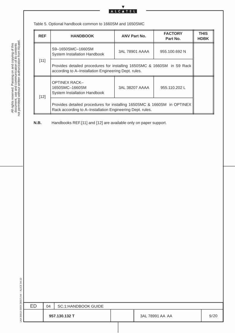
Table 5. Optional handbook common to 1660SM and 1650SMC
REF HANDBOOK ANV Part No.FACTORYPart No.
THISHDBK
S9–1650SMC–1660SMSystem Installation Handbook
3AL 78901 AAAA 955.100.692 N
[11]Provides detailed procedures for installing 1650SMC & 1660SM in S9 Rackaccording to A–Installation Engineering Dept. rules.
OPTINEX RACK–1650SMC–1660SMSystem Installation Handbook
3AL 38207 AAAA 955.110.202 L
[12]
Provides detailed procedures for installing 1650SMC & 1660SM in OPTINEXRack according to A–Installation Engineering Dept. rules.
N.B. Handbooks REF.[11] and [12] are available only on paper support.

All
right
s re
serv
ed. P
assi
ng o
n an
d co
pyin
g of
this
docu
men
t, us
e an
d co
mm
unic
atio
n of
its
cont
ents
not p
erm
itted
with
out w
ritte
n au
thor
izat
ion
from
Alc
atel
.
ED
1AA
000
14 0
004
(900
7) A
4 –
ALI
CE
04.
10
10
04
957.130.132 T
SC.1:HANDBOOK GUIDE
/3AL 78991 AA AA
20
20
All
right
s re
serv
ed. P
assi
ng o
n an
d co
pyin
g of
this
docu
men
t, us
e an
d co
mm
unic
atio
n of
its
cont
ents
not p
erm
itted
with
out w
ritte
n au
thor
izat
ion
from
Alc
atel
.
ED
1AA
000
14 0
004
(900
7) A
4 –
ALI
CE
04.
10
11
04
957.130.132 T
SC.1:HANDBOOK GUIDE
/3AL 78991 AA AA
20
20
3 SAFETY NORMS AND LABELS
3.1 First aid for electric shock
Do not touch the patient with bare hands until the circuit has been opened.
Open the circuit by switching off the line switches. If that is not possible, protect yourself with drymaterial and free the patient from the conductor.
ARTIFICIAL RESPIRATION
It is important to start mouth to mouth resuscitation at once and seek doctor help immediately.
TREATMENT OF BURNS
This treatment should be used after the patient has regained consciousness. It can also be employed whilethe artificial respiration is being applied (in this case there should be at least two persons present).
WARNING:
• Do not attempt to remove his clothing from the burnt parts;
• Apply dry gauze on the burns;
• Do not apply ointments or other oily substances.
All
right
s re
serv
ed. P
assi
ng o
n an
d co
pyin
g of
this
docu
men
t, us
e an
d co
mm
unic
atio
n of
its
cont
ents
not p
erm
itted
with
out w
ritte
n au
thor
izat
ion
from
Alc
atel
.
ED
1AA
000
14 0
004
(900
7) A
4 –
ALI
CE
04.
10
12
04
957.130.132 T
SC.1:HANDBOOK GUIDE
/3AL 78991 AA AA
20
20
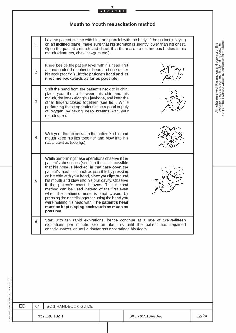
Mouth to mouth resuscitation method
1
2
3
4
5
6
Lay the patient supine with his arms parallel with the body, if the patient is layingon an inclined plane, make sure that his stomach is slightly lower than his chest.Open the patient’s mouth and check that there are no extraneous bodies in hismouth (dentures, chewing–gum etc.),
Kneel beside the patient level with his head. Puta hand under the patient’s head and one underhis neck (see fig.) Lift the patient’s head and letit recline backwards as far as possible
Shift the hand from the patient’s neck to is chin:place your thumb between his chin and hismouth, the index along his jawbone, and keep theother fingers closed together (see fig.). Whileperforming these operations take a good supplyof oxygen by taking deep breaths with yourmouth open.
With your thumb between the patient’s chin andmouth keep his lips together and blow into hisnasal cavities (see fig.)
While performing these operations observe if thepatient’s chest rises (see fig.) If not it is possiblethat his nose is blocked: in that case open thepatient’s mouth as much as possible by pressingon his chin with your hand, place your lips aroundhis mouth and blow into his oral cavity. Observeif the patient’s chest heaves. This secondmethod can be used instead of the first evenwhen the patient’s nose is kept closed bypressing the nostrils together using the hand youwere holding his head with. The patient’s headmust be kept sloping backwards as much aspossible.
Start with ten rapid expirations, hence continue at a rate of twelve/fifteenexpirations per minute. Go on like this until the patient has regainedconsciousness, or until a doctor has ascertained his death.
All
right
s re
serv
ed. P
assi
ng o
n an
d co
pyin
g of
this
docu
men
t, us
e an
d co
mm
unic
atio
n of
its
cont
ents
not p
erm
itted
with
out w
ritte
n au
thor
izat
ion
from
Alc
atel
.
ED
1AA
000
14 0
004
(900
7) A
4 –
ALI
CE
04.
10
13
04
957.130.132 T
SC.1:HANDBOOK GUIDE
/3AL 78991 AA AA
20
20
3.2 Norms and labels
Refer to the Technical Handbook associated to ALCATEL’s designed and manufactured equipmentto obtain the following information:
– COMPLIANCE WITH EUROPEAN NORMS.
– SAFETY RULES
• General rules
• Harmful optical signals
• Risk of explosion
• Moving mechanical parts
• Heat–radiating Mechanical Parts
– ELECTROMAGNETIC COMPATIBILITY
– ELECTROSTATIC DISCHARGERS (ESD)
– EQUIPMENT LABELS
Identical or similar information on Personal Computer, Work–Station etc., other than ALCATEL’s, loadedwith software applicative described in this Handbook, is supplied in the Constructor’s technicaldocumentation.

All
right
s re
serv
ed. P
assi
ng o
n an
d co
pyin
g of
this
docu
men
t, us
e an
d co
mm
unic
atio
n of
its
cont
ents
not p
erm
itted
with
out w
ritte
n au
thor
izat
ion
from
Alc
atel
.
ED
1AA
000
14 0
004
(900
7) A
4 –
ALI
CE
04.
10
14
04
957.130.132 T
SC.1:HANDBOOK GUIDE
/3AL 78991 AA AA
20
20

All
right
s re
serv
ed. P
assi
ng o
n an
d co
pyin
g of
this
docu
men
t, us
e an
d co
mm
unic
atio
n of
its
cont
ents
not p
erm
itted
with
out w
ritte
n au
thor
izat
ion
from
Alc
atel
.
ED
1AA
000
14 0
004
(900
7) A
4 –
ALI
CE
04.
10
15
04
957.130.132 T
SC.1:HANDBOOK GUIDE
/3AL 78991 AA AA
20
20
4 HANDBOOK DESCRIPTION
This handbook is composed of the following Manuals:
SECTION 1: HANDBOOK GUIDE (This document)
The Handbook Guide gives general information on the application and use of the Handbook. TheHandbook Guide includes the following chapters:– Chapter 1: Handbook structure and configuration check. This chapter gives information on the whole
handbook application, composition and evolution.– Chapter 2: Product-release handbooks. This chapter lists the handbooks the Operator should have
in order to carry out the tasks allowed by the specific product–release this handbook refers to.– Chapter 3: Safety norms and labels– Chapter 4: Handbook description– Chapter 5: General on Alcatel Customer Documentation
SECTION 2: INTRODUCTION Manual
The Introduction Manual describes the main features of the graphical interface and provides a generaloverview of the system architecture and the different functionalities provided by the Craft Terminal. TheIntroduction Manual includes the following chapters:– Chapter 1: Introduction. This chapter gives the structure of this manual.– Chapter 2: General description of the Craft Terminal. The Craft Terminal is introduced and the
software product listed. The Craft Terminal main functionality in the NE management (EML–USM)are listed and briefly described.
– Chapter 3: Acronyms and abbreviations. The acronyms used in all the operator manuals are listed.– Chapter 4: Glossary of terms. Definitions concerning the acronyms.
SECTION 3: NETWORK ELEMENT MANAGEMENT Manual
The aim of this document is to describe the Craft Terminal view, inserting operative information.The Network Element Manual includes the following chapters:
– Chapter 1: Introduction. This chapter gives the structure of this manual.– Chapter 2: General introduction on views and menus. The view organization is presented and the
menus available listed and briefly described.– Chapter 3: NE management supervision. This chapter is dedicated to the NE states and NE access.– Chapter 4: NE management general configuration. In this chapter general configuration referred to
the equipment management are described (CT access, NE Time, Alarm Configuration etc).– Chapter 5: Security Management. In this chapter configuration referred to the Security management
are described (ACD level and Manager list).– Chapter 6: External input and output points management. This chapter describes how to display and
set the input/output environmental alarm (housekeeping alarm).– Chapter 7: Diagnosis management. In this chapter are specified: access to the Alarm Surveillance
to show the alarm condition, abnormal condition list (as result of operator’s command), access to theEvent Log file.
– Chapter 8: Communication and Routing management. In this chapter are presented thecommunication and routing parameters, concerning the communication protocols for the local NE,the OS and each other related NE in order to provide a global communication capabilities inside thenetwork
– Chapter 9: Equipment management. This chapter deals mainly with the setting and changing of theboards present on the Equipment and undertaking board protection operations.
– Chapter 10: Board view. This chapter permits to show the physical port available in a specific board(alarm synthesis and port symbol) and to access the port view.
All
right
s re
serv
ed. P
assi
ng o
n an
d co
pyin
g of
this
docu
men
t, us
e an
d co
mm
unic
atio
n of
its
cont
ents
not p
erm
itted
with
out w
ritte
n au
thor
izat
ion
from
Alc
atel
.
ED
1AA
000
14 0
004
(900
7) A
4 –
ALI
CE
04.
10
16
04
957.130.132 T
SC.1:HANDBOOK GUIDE
/3AL 78991 AA AA
20
20
– Chapter 11: Port view. This chapter permits to set and show the transmission resources referred tothe Port.
– Chapter 12: Equipment protection management. This chapter permits to manage the EPS protection,setting the relevant configuration.
– Chapter 13: Multiplex Section protection management. This chapter permits to manage the MSPprotection.
– Chapter 14: Transmission view. This chapter permits to show and set the Termination Point of theequipment, thus having an overview of the complete signal flow of the various port.
– Chapter 15: Cross connection management. This chapter permits to manage the connection of thepaths.
– Chapter 16: Overhead management. This chapter permits to manage the Overhead, setting therelevant configuration.
– Chapter 17: Performance Monitoring management. This chapter permits to set and showPerformance Monitoring parameters and data.
– Chapter 18: Synchronization management. This chapter permits to set and show Synchronizationparameters and status.
– Chapter 19: Software management. This chapter permits to update the NE by means downloadprocedure and to manage NE software.
SECTION 4: NETWORK ELEMENT MAINTENANCE Manual
This document aims at introducing the Maintenance procedure, inserting information useful to identifyalarms and troubleshoot the NE.The Maintenance Manual includes the following chapters:
– Chapter 1: Introduction. This chapter gives the structure of this manual.– Chapter 2: Maintenance introduction. List the maintenance steps.– Chapter 3: Maintenance of the Personal Computer. The Personal Computer manual is referred.– Chapter 4: Problems with Craft terminal. Shut–down and restart of the PC is indicated.– Chapter 5: Troubleshooting (Corrective Maintenance). Detection location and correction of failure
are presented.– Chapter 6: Unit replacement with spare. The replacement procedure is detailed.– Chapter 7: Upgrading with New Hardware. The Hardware upgrading procedure is detailed.
SECTION 5: SIBDL Manual
This document describes the download procedure with SIBDL.The SIBDL Manual includes the following chapters:
– Chapter 1: Introduction– Chapter 2: Download with SIBDL configuration– Chapter 3: Configuration for SIBDL

All
right
s re
serv
ed. P
assi
ng o
n an
d co
pyin
g of
this
docu
men
t, us
e an
d co
mm
unic
atio
n of
its
cont
ents
not p
erm
itted
with
out w
ritte
n au
thor
izat
ion
from
Alc
atel
.
ED
1AA
000
14 0
004
(900
7) A
4 –
ALI
CE
04.
10
17
04
957.130.132 T
SC.1:HANDBOOK GUIDE
/3AL 78991 AA AA
20
20
5 GENERAL ON ALCATEL CUSTOMER DOCUMENTATION
5.1 Products, product-releases, versions and Customer Documentation
A ”product” is defined by the network hierarchical level where it can be inserted and by the whole ofperformance and services for which it is meant.A ”product” evolves through successive ”product-releases” which are the real products marketed fortheir delivery at a certain ”product-release” availability date.
So, a ”product–release” defines a set of hardware components and a software package which, as a whole,identify the possible network applications and the equipment performance which the specific”product-release” has been designed, engineered and marketed for.
In some cases a ”product-release” has further development steps, named ”versions”, that are born toimprove or add some performance (mainly software) with respect to the previous version, or for bug fixingpurposes.
A ”product-release” has its own standard Customer Documentation, composed by one or morehandbooks.
A new ”version” of a ”product-release” may or may not produce a change in the status of the CustomerDocumentation set, as described in para.5.4 on page 18.
5.2 Handbook supply to Customers
Handbooks are not automatically delivered together with the equipment they refer to.The number of handbooks per type to be supplied must be decided at contract level.
5.3 Aims of standard Customer Documentation
Standard Customer Documentation, referred to hereafter, must be always meant as plant-independent.Plant-dependent documentation, if envisaged by the contract, is subjected to commercial criteria as faras contents, formats and supply conditions are concerned (plant-dependent documentation is notdescribed here).
Standard hardware and software documentation is meant to give the Customer personnel the possibilityand the information necessary for installing, commissioning, operating and maintaining the equipmentaccording to Alcatel–Telecom Laboratory design choices.In particular the contents of the handbooks associated to the software applications focus on theexplanation of the man-machine interface and of the operating procedures allowed by it.
Consequently, no supply to the Customers of design documentation (like software source programs,programming tools, etc.) is envisaged.
All
right
s re
serv
ed. P
assi
ng o
n an
d co
pyin
g of
this
docu
men
t, us
e an
d co
mm
unic
atio
n of
its
cont
ents
not p
erm
itted
with
out w
ritte
n au
thor
izat
ion
from
Alc
atel
.
ED
1AA
000
14 0
004
(900
7) A
4 –
ALI
CE
04.
10
18
04
957.130.132 T
SC.1:HANDBOOK GUIDE
/3AL 78991 AA AA
20
20
5.4 Handbook Updating
The handbooks associated to the ”product–release” are listed in para.2 on page 7.Each handbook is identified by:– the name of the ”product-release” (and ”version” when the handbook is applicable to the versions
starting from it, but not to the previous ones),– the handbook name,– the handbook P/N,– the handbook edition (usually first edition=01),– the handbook issue date. The date on the handbook does not refer to the date of print but to the date
on which the handbook source file has been completed and released for the production.
5.4.1 Changes introduced in the same product-release (same handbook P/N)
The edition and date of issue might change on future handbook versions for the following reasons:
– only the date changes (pointed out in the Table of Contents) when modifications are made to theeditorial system not changing the technical contents of the handbook.
– the edition, hence the date, is changed because modifications made concern technical contents. Inthis case:• the table in para.1.4 on page 5 indicates the section(s) edition change;• in each section, the main changes with respect to the previous edition are listed;• in affected chapters of each section, revision bars on the left of the page indicate modifications
in text and drawings (this is done after the first officially released and validated version).
Changes concerning the technical contents of the handbook cause the edition number increase (e.g. fromEd.01 to Ed.02). Slight changes (e.g. for corrections) maintain the same edition but with the addition ofa version character (e.g. from Ed.02 to Ed.02A).
NOTES FOR HANDBOOKS RELEVANT TO SOFTWARE APPLICATIONS
Handbooks relevant to software applications (typically the Operator’s Handbooks) are notmodified unless the new software ”version” distributed to Customers implies man–machineinterface changes or in case of slight modifications not affecting the understanding of theexplained procedures.Moreover, should the screen prints included in the handbook contain the product-release’s”version” marking, they are not replaced in the handbooks related to a subsequent version, ifthe screen contents are unchanged.
5.4.2 Supplying updated handbooks to Customers
Supplying updated handbooks to Customers who have already received previous issues is submitted tocommercial criteria.By updated handbook delivery it is meant the supply of a complete copy of the handbook new issue(supplying errata–corrige sheets is not envisaged).
5.4.3 Changes due to a new product-releaseA new product-release changes the handbook P/N and the edition starts from 01. In this case the modifiedparts of the handbook are not listed.
All
right
s re
serv
ed. P
assi
ng o
n an
d co
pyin
g of
this
docu
men
t, us
e an
d co
mm
unic
atio
n of
its
cont
ents
not p
erm
itted
with
out w
ritte
n au
thor
izat
ion
from
Alc
atel
.
ED
1AA
000
14 0
004
(900
7) A
4 –
ALI
CE
04.
10
19
04
957.130.132 T
SC.1:HANDBOOK GUIDE
/3AL 78991 AA AA
20
20
5.5 Customer documentation supply on CD–ROM
In the following ’CD–ROM’ means ’Customer Documentation on CD–ROM’
5.5.1 Contents, creation and production of a CD–ROM
In most cases, a CD–ROM contains the documentation of one product–release(–version) and for a certainlanguage.In some other cases, the same CD–ROM can contain the documentation of differentproduct–release(–version)s for a certain language.
As a general rule:
– CD–ROMs for Network Management products do not contain:
• the Installation Guides
• the documentation of system optional features that Customers could not buy from Alcateltogether with the main applicative SW.
– CD–ROMs for Network Elements products do not contain:
• the Installation Handbooks
• the Turn–Up and Commissioning Handbooks
• the documentation of system optional features (e.g. System Installation Handbooks related toracks that Customers could not buy from Alcatel together with the main equipment).
A CD–ROM is obtained collecting various handbooks and processing them byInterleaf–World–View–Press after the manual addition of some hyperlinks which make the navigationthrough the various handbooks easier. No additional information is added to each handbook, so that thedocumentation present in the CD–ROMs is exactly the same the Customer would receive on paper.
The files processed in this way are then transferred on a PC where the viewer (Interleaf–World–View) isadded and a master CD–ROM is recorded.
Suitable checks are made in order to have a virus–free product.
After a complete functional check, the CD–ROM image is electronically transferred to the archive of theProduction Department, so that the CD–ROM can be produced and delivered to Customers.
All
right
s re
serv
ed. P
assi
ng o
n an
d co
pyin
g of
this
docu
men
t, us
e an
d co
mm
unic
atio
n of
its
cont
ents
not p
erm
itted
with
out w
ritte
n au
thor
izat
ion
from
Alc
atel
.
ED
1AA
000
14 0
004
(900
7) A
4 –
ALI
CE
04.
10
20
04
957.130.132 T
SC.1:HANDBOOK GUIDE
/3AL 78991 AA AA
20
20
5.5.2 Use of the CD–ROM
The CD–ROM can be used both in PC and Unix WS environments.
The minimum configuration for World View (rel.2.2.2) utilization on a PC is:
– Operative System: Windows 95 or Windows NT (3.51 and 4.00)– Processor: Intel 486– RAM: 16Mbyte– Disk space: 20Mbyte
The set–up procedure is present in the booklet included in the CD–ROM box.After the set–up procedure, which installs the viewer in the PC or Unix WS environment, the Customeris allowed to read the handbooks on the PC/WS screen, using the navigation and zooming tools includedin the viewer, and to print selected parts of the documentation through a local printer.
N.B. Copyright notification
WorldView: Copyright 1981–1996INTERLEAF Inc.All rights reserved.The use of WorldView is permitted only in association with the files containedin the CD–ROMs officially supplied by Alcatel.
Alcatel documents: All rights reserved.Passing and copying of documents and files contained in the CD–ROMsofficially supplied by Alcatel, use and communication of its contents are notpermitted without written authorization from Alcatel.
5.5.3 CD–ROM identification
Each CD–ROM is identified:
1 ) by the following external identifiers, that are printed both on the booklet and the CD–ROM uppersurface:– the name of the ”product–release(s)” (and ”version” when the CD–ROM is applicable to
the versions starting from it, but not to the previous ones),– a writing indicating the language(s),– the CD–ROM P/N (Factory P/N 417.xxx.xxx x and ANV P/N),– the CD–ROM edition (usually first edition=01)
2 ) and, internally, by the list of the source handbooks and documents (P/Ns and editions) by whosecollection and processing the CD–ROM itself has been created.
5.5.4 CD–ROM updating
The list of source handbook/document P/Ns–editions indicated in previous para.5.5.3 point 2 ) , inassociation with the CD–ROM’s own P/N–edition, is also loaded in the Alcatel–Information–System as astructured list.Whenever a new edition of any of such handbooks/documents is released in the Alcatel archive system,the Alcatel–Information–System automatically rises a warning toward the Customer Documentationdepartment, indicating the list of CD–ROMs that must be updated to include the new editions of thesehandbooks/documents.This causes the planning and creation of a new edition of the CD–ROM.Updating of CD–ROMs always follows, with a certain delay, the updating of the single handbookscomposing the collection.
END OF DOCUMENT
All
right
s re
serv
ed. P
assi
ng o
n an
d co
pyin
g of
this
docu
men
t, us
e an
d co
mm
unic
atio
n of
its
cont
ents
not p
erm
itted
with
out w
ritte
n au
thor
izat
ion
from
Alc
atel
.
ED
1AA
000
14 0
004
(900
7) A
4 –
ALI
CE
04.
10
1
03
957.130.132 T
SC.2:INTRODUCTION
/3AL 78991 AA AA
16
16
1660SM REL.1.1 C.T. OPERATOR’S HANDBOOK
TABLE OF CONTENTS
LIST OF FIGURES AND TABLES 2. . . . . . . . . . . . . . . . . . . . . . . . . . . . . . . . . . . . . . . . . . . . . . . . . . . . . . .
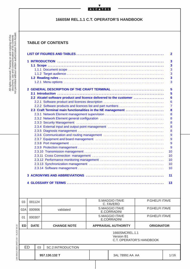
1 INTRODUCTION 3. . . . . . . . . . . . . . . . . . . . . . . . . . . . . . . . . . . . . . . . . . . . . . . . . . . . . . . . . . . . . . . . . . . 1.1 Scope 3. . . . . . . . . . . . . . . . . . . . . . . . . . . . . . . . . . . . . . . . . . . . . . . . . . . . . . . . . . . . . . . . . . . . . . . . .
1.1.1 Document scope 3. . . . . . . . . . . . . . . . . . . . . . . . . . . . . . . . . . . . . . . . . . . . . . . . . . . . . . . . . . . . 1.1.2 Target audience 3. . . . . . . . . . . . . . . . . . . . . . . . . . . . . . . . . . . . . . . . . . . . . . . . . . . . . . . . . . . . .
1.2 Reading rules 3. . . . . . . . . . . . . . . . . . . . . . . . . . . . . . . . . . . . . . . . . . . . . . . . . . . . . . . . . . . . . . . . . . 1.2.1 Menu options 3. . . . . . . . . . . . . . . . . . . . . . . . . . . . . . . . . . . . . . . . . . . . . . . . . . . . . . . . . . . . . . .
2 GENERAL DESCRIPTION OF THE CRAFT TERMINAL 5. . . . . . . . . . . . . . . . . . . . . . . . . . . . . . . . . 2.1 Introduction 5. . . . . . . . . . . . . . . . . . . . . . . . . . . . . . . . . . . . . . . . . . . . . . . . . . . . . . . . . . . . . . . . . . . 2.2 Alcatel software product and licence delivered to the customer 6. . . . . . . . . . . . . . . . . . .
2.2.1 Software product and licences description 6. . . . . . . . . . . . . . . . . . . . . . . . . . . . . . . . . . . . . . 2.2.2 Software products and licences list and part numbers 7. . . . . . . . . . . . . . . . . . . . . . . . . . . .
2.3 Craft Terminal main functionalities in the NE management 8. . . . . . . . . . . . . . . . . . . . . . . . 2.3.1 Network Element management supervision 8. . . . . . . . . . . . . . . . . . . . . . . . . . . . . . . . . . . . . 2.3.2 Network Element general configuration 8. . . . . . . . . . . . . . . . . . . . . . . . . . . . . . . . . . . . . . . . 2.3.3 Security Management 8. . . . . . . . . . . . . . . . . . . . . . . . . . . . . . . . . . . . . . . . . . . . . . . . . . . . . . . 2.3.4 External input and output point management 8. . . . . . . . . . . . . . . . . . . . . . . . . . . . . . . . . . . 2.3.5 Diagnosis management 8. . . . . . . . . . . . . . . . . . . . . . . . . . . . . . . . . . . . . . . . . . . . . . . . . . . . . . 2.3.6 Communication and routing management 9. . . . . . . . . . . . . . . . . . . . . . . . . . . . . . . . . . . . . . 2.3.7 Equipment and board management 9. . . . . . . . . . . . . . . . . . . . . . . . . . . . . . . . . . . . . . . . . . . 2.3.8 Port management 9. . . . . . . . . . . . . . . . . . . . . . . . . . . . . . . . . . . . . . . . . . . . . . . . . . . . . . . . . . . 2.3.9 Protection management 9. . . . . . . . . . . . . . . . . . . . . . . . . . . . . . . . . . . . . . . . . . . . . . . . . . . . . . 2.3.10 Transmission management 10. . . . . . . . . . . . . . . . . . . . . . . . . . . . . . . . . . . . . . . . . . . . . . . . . . 2.3.11 Cross Connection management 10. . . . . . . . . . . . . . . . . . . . . . . . . . . . . . . . . . . . . . . . . . . . . 2.3.12 Performance monitoring management 10. . . . . . . . . . . . . . . . . . . . . . . . . . . . . . . . . . . . . . . . 2.3.13 Synchronization management 10. . . . . . . . . . . . . . . . . . . . . . . . . . . . . . . . . . . . . . . . . . . . . . . 2.3.14 Software management 10. . . . . . . . . . . . . . . . . . . . . . . . . . . . . . . . . . . . . . . . . . . . . . . . . . . . . .
3 ACRONYMS AND ABBREVIATIONS 11. . . . . . . . . . . . . . . . . . . . . . . . . . . . . . . . . . . . . . . . . . . . . . . . .
4 GLOSSARY OF TERMS 13. . . . . . . . . . . . . . . . . . . . . . . . . . . . . . . . . . . . . . . . . . . . . . . . . . . . . . . . . . . . .
ED DATE CHANGE NOTE APPRAISAL AUTHORITY ORIGINATOR
01 000307 S.MAGGIO ITAVE P.GHELFI ITAVE
02A 000906 validated S.MAGGIO ITAVE P.GHELFI ITAVE
00112403 S.MAGGIO ITAVE P.GHELFI ITAVE
1660SMCREL.1.1Version B1C.T. OPERATOR’S HANDBOOK
E.CORRADINI
E.CORRADINI
C. FAVERO
All
right
s re
serv
ed. P
assi
ng o
n an
d co
pyin
g of
this
docu
men
t, us
e an
d co
mm
unic
atio
n of
its
cont
ents
not p
erm
itted
with
out w
ritte
n au
thor
izat
ion
from
Alc
atel
.
ED
1AA
000
14 0
004
(900
7) A
4 –
ALI
CE
04.
10
2
03
957.130.132 T
SC.2:INTRODUCTION
/3AL 78991 AA AA
16
16
LIST OF FIGURES AND TABLES
Table 1. Software products part numbers 7. . . . . . . . . . . . . . . . . . . . . . . . . . . . . . . . . . . . . . . . . . . . . . . . . Table 2. Software licence part numbers 7. . . . . . . . . . . . . . . . . . . . . . . . . . . . . . . . . . . . . . . . . . . . . . . . . .
All
right
s re
serv
ed. P
assi
ng o
n an
d co
pyin
g of
this
docu
men
t, us
e an
d co
mm
unic
atio
n of
its
cont
ents
not p
erm
itted
with
out w
ritte
n au
thor
izat
ion
from
Alc
atel
.
ED
1AA
000
14 0
004
(900
7) A
4 –
ALI
CE
04.
10
3
03
957.130.132 T
SC.2:INTRODUCTION
/3AL 78991 AA AA
16
16
1 INTRODUCTION
1.1 Scope
1.1.1 Document scope
The Introduction Manual present the Craft Terminal main functions and provides a general overview of thedifferent functionalities provided by the ELM–USM of the Craft Terminal for Info Model NE.
1.1.2 Target audience
The Introduction Manual is intended for all users.
The documents that should be read before starting this document are:
– 1320CT Rel. 1.1 Basic Operator’s Handbook
1.2 Reading rules
1.2.1 Menu options
All the manuals describe menus, but not necessarily all the options of these menus. When a menu optionis not detailed in a manual, the information are surely given in another manual.

All
right
s re
serv
ed. P
assi
ng o
n an
d co
pyin
g of
this
docu
men
t, us
e an
d co
mm
unic
atio
n of
its
cont
ents
not p
erm
itted
with
out w
ritte
n au
thor
izat
ion
from
Alc
atel
.
ED
1AA
000
14 0
004
(900
7) A
4 –
ALI
CE
04.
10
4
03
957.130.132 T
SC.2:INTRODUCTION
/3AL 78991 AA AA
16
16
All
right
s re
serv
ed. P
assi
ng o
n an
d co
pyin
g of
this
docu
men
t, us
e an
d co
mm
unic
atio
n of
its
cont
ents
not p
erm
itted
with
out w
ritte
n au
thor
izat
ion
from
Alc
atel
.
ED
1AA
000
14 0
004
(900
7) A
4 –
ALI
CE
04.
10
5
03
957.130.132 T
SC.2:INTRODUCTION
/3AL 78991 AA AA
16
16
2 GENERAL DESCRIPTION OF THE CRAFT TERMINAL
2.1 Introduction
The Craft Terminal is a project in charge of the local management of single network elements, providingITU– compliant Information Model Interface to the Network Element.Multiple NE management up to 32 Network element is possible obtaining a remote Craft Terminalapplication.
The general information of the Craft Terminal are presented in the Basic Craft Terminal Operator’sHandbook, that the operator have to read before this Handbook.
In the Basic Craft Terminal Operator’s Handbook are described all the general description of use,navigation, rules, etc, common to all the NE using the same Craft Terminal.
Further, the same handbook contains the detailed description of common operations as “Installation” andcommon screens as “Network Element Synthesis view”.
The Network Element Synthesis view is the first view presented to the operator entering the application.
Starting from this view it is possible login the NE and than enter the EML–USM views.
This Operator’s Handbook deals with the EML–USM views of the Craft Terminal, which directlypermit to manage the Network Element.
The management main functions of the EML–USM are inserted at para. 2.3 on page 8.
A detailed description of the EML–USM screens is given in Section Ne Management of this handbook.
The list and part numbers of the software products distributed by Alcatel is inserted in para.2.2 on page6.
The Craft Terminal characteristic (computer configuration) are listed in the Basic Craft Terminal Operator’sHandbook.
All
right
s re
serv
ed. P
assi
ng o
n an
d co
pyin
g of
this
docu
men
t, us
e an
d co
mm
unic
atio
n of
its
cont
ents
not p
erm
itted
with
out w
ritte
n au
thor
izat
ion
from
Alc
atel
.
ED
1AA
000
14 0
004
(900
7) A
4 –
ALI
CE
04.
10
6
03
957.130.132 T
SC.2:INTRODUCTION
/3AL 78991 AA AA
16
16
2.2 Alcatel software product and licence delivered to the customer
2.2.1 Software product and licences description
The software products are distributed by Alcatel in a CD–ROM.
In this CD–ROM are contained:
• Software packages for NE management by means of the craft terminal
• Software package of the NE, to be installed in the NE or update the NE (by means of downloadfunction)
The software package used for management permits the dialogue between craft terminal and NE, torealize all the functions of the NES and EML–USM ).
The software package used for updating the NE must be installed on the PC and then downloaded onthe NE, thus following product evolution.
Alcatel typically offers several software licences on the software product (only one for this equipment)
They are referred both to the Network Element software features and to the Craft Terminal softwarefeatures.
All
right
s re
serv
ed. P
assi
ng o
n an
d co
pyin
g of
this
docu
men
t, us
e an
d co
mm
unic
atio
n of
its
cont
ents
not p
erm
itted
with
out w
ritte
n au
thor
izat
ion
from
Alc
atel
.
ED
1AA
000
14 0
004
(900
7) A
4 –
ALI
CE
04.
10
7
03
957.130.132 T
SC.2:INTRODUCTION
/3AL 78991 AA AA
16
16
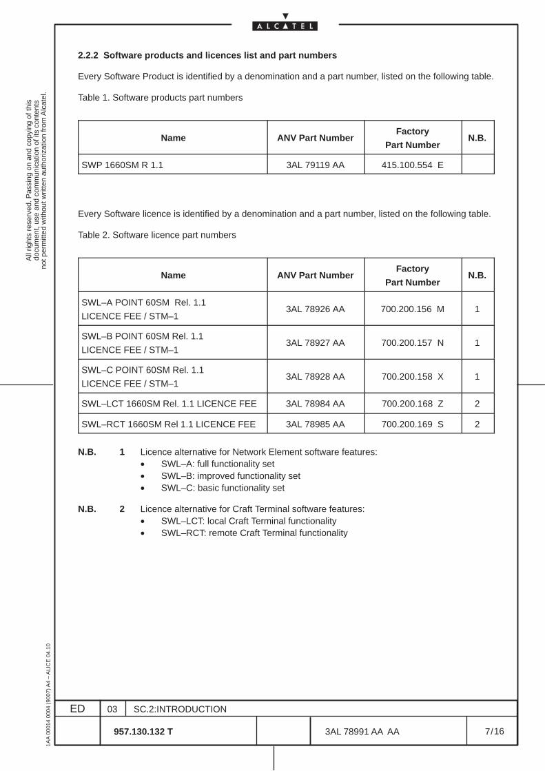
2.2.2 Software products and licences list and part numbers
Every Software Product is identified by a denomination and a part number, listed on the following table.
Table 1. Software products part numbers
Name ANV Part NumberFactory
Part NumberN.B.
SWP 1660SM R 1.1 3AL 79119 AA 415.100.554 E
Every Software licence is identified by a denomination and a part number, listed on the following table.
Table 2. Software licence part numbers
Name ANV Part NumberFactory
Part NumberN.B.
SWL–A POINT 60SM Rel. 1.1
LICENCE FEE / STM–13AL 78926 AA 700.200.156 M 1
SWL–B POINT 60SM Rel. 1.1
LICENCE FEE / STM–13AL 78927 AA 700.200.157 N 1
SWL–C POINT 60SM Rel. 1.1
LICENCE FEE / STM–13AL 78928 AA 700.200.158 X 1
SWL–LCT 1660SM Rel. 1.1 LICENCE FEE 3AL 78984 AA 700.200.168 Z 2
SWL–RCT 1660SM Rel 1.1 LICENCE FEE 3AL 78985 AA 700.200.169 S 2
N.B. 1 Licence alternative for Network Element software features:• SWL–A: full functionality set• SWL–B: improved functionality set• SWL–C: basic functionality set
N.B. 2 Licence alternative for Craft Terminal software features:• SWL–LCT: local Craft Terminal functionality• SWL–RCT: remote Craft Terminal functionality
All
right
s re
serv
ed. P
assi
ng o
n an
d co
pyin
g of
this
docu
men
t, us
e an
d co
mm
unic
atio
n of
its
cont
ents
not p
erm
itted
with
out w
ritte
n au
thor
izat
ion
from
Alc
atel
.
ED
1AA
000
14 0
004
(900
7) A
4 –
ALI
CE
04.
10
8
03
957.130.132 T
SC.2:INTRODUCTION
/3AL 78991 AA AA
16
16
2.3 Craft Terminal main functionalities in the NE management
In this chapter, are described the main functionalities of the Craft Terminal, referred to the Network Elementmanagement views, obtained by means EML–USM. The functionalities constitute the heading of each ofthe paragraphs below.
2.3.1 Network Element management supervision
Deals with the NE state and access.
2.3.2 Network Element general configuration
Deals with the general configuration of the equipment.
– Craft Terminal access state (allow or inhibit)– NE Time management– Alarms Configuration
• Alarm Severity Assignment Profile management,• Allow/Inhibit alarm notification,• Alarm re–synchronization.
– Restart NE
2.3.3 Security Management
Deals with the security configuration of the equipment.
– Set Manager list– Set ACD level
2.3.4 External input and output point management
Deals with housekeeping signals input from the external (station alarms) or forwarded (output) towardsthe external.
– Display External points– Configure External points
2.3.5 Diagnosis management
For real time alarm reporting and subsequent fault localization and correction.– Alarm Surveillance
The alarms concerning a particular managed entity will be represented in a synthetic way in all theviews concerning the entity.Alarms information are detailed in the Alarms Surveillance Manual
– Abnormal Condition list ( as result of operator’s commands)
– Event log ManagerPermits to have access to the Event Log file.
– Remote Inventory (”upload” and “view” remote inventory)

All
right
s re
serv
ed. P
assi
ng o
n an
d co
pyin
g of
this
docu
men
t, us
e an
d co
mm
unic
atio
n of
its
cont
ents
not p
erm
itted
with
out w
ritte
n au
thor
izat
ion
from
Alc
atel
.
ED
1AA
000
14 0
004
(900
7) A
4 –
ALI
CE
04.
10
9
03
957.130.132 T
SC.2:INTRODUCTION
/3AL 78991 AA AA
16
16
2.3.6 Communication and routing management
This deals with the configuration parameters concerning the communication protocols for the local NE,the OS and each other related NE. Different types of protection can be managed:
– Local NE and OS addresses– NTP configurations– LAPD, Ethernet, MESA, RAP configurations
2.3.7 Equipment and board management
Deals with the presentation of the equipment and the hierarchical tree structure, permitting to define thetypes of boards present. The Board view permits to access the Port view.
– Set / modify / remove boards– Software information of the selected board.– Remote Inventory
2.3.8 Port management
This permits to set and show the transmission resources (TP) referred only to the port (SDH PDH, HOA).It is used to check the detailed alarm of each TP and to configure them (many options are the same ofthe Transmission view).
For each port a specific menu is available where various configuration of the specific port can be set, forexample:
– Automatic Laser Shutdown– MSP protection– Loopback management and configuration– Single fiber configuration
Port view is also the entry point of other “management functions” :
– Performance Monitoring management– Cross Connection management
For each port are presented:
– the various ITU–T functional blocks (i.e. PPI, RST, VC4).– details of alarm and state condition– TP role, connection, etc. information
2.3.9 Protection management
This deals with the protection mechanism that is possible to configure in the NE. Different types ofprotection can be managed:
– Equipment protection switching– Multiple Section Protection
All
right
s re
serv
ed. P
assi
ng o
n an
d co
pyin
g of
this
docu
men
t, us
e an
d co
mm
unic
atio
n of
its
cont
ents
not p
erm
itted
with
out w
ritte
n au
thor
izat
ion
from
Alc
atel
.
ED
1AA
000
14 0
004
(900
7) A
4 –
ALI
CE
04.
10
10
03
957.130.132 T
SC.2:INTRODUCTION
/3AL 78991 AA AA
16
16
2.3.10 Transmission management
This permits to cover the management of the transmission resources, opening the views of all the specificports of the NE (SDH and PDH).It supply an overview of the complete signal flow.For all the ports are presented:
– the various ITU–T functional blocks (i.e. PPI, RST, VC4).– synthesis of alarm and state condition– TP role, connection, etc. information
For each port a specific menu is available similar to the Port view where various configuration of thespecific port can be set.
Also Transmission view is than the entry point of other “management functions” .
2.3.11 Cross Connection management
This deals with the connection of all the Termination Point (TP), which are the starting and terminatingpoints of a transmission segment. In this way the multiplex structures are created, managing the trafficflow. Similar operation are made on the OverHead cross connections.
– Create / modify cross connections– Activate / deactivate / switch cross connections
2.3.12 Performance monitoring management
This function deals with the set up, collect, log and display performance data associated with the managedNE according ITU–T G.826.It consists of a set of functions that evaluate and report on the behavior of theNEs and their effectiveness relating to the communications taking place on the Network.
– Set up the Performance Monitoring thresholds– Collect and display Performance Monitoring data– Performance Monitoring history
2.3.13 Synchronization management
Deals with the management of the timing.
– Timing source, SSU, T0, T4 configuration– Protection commands
2.3.14 Software management
Deals with the manipulation of the software package within NE.
– Software download refers to the NE software, permitting to charge the software in the relevant NEto upgrade the NE software, thus following product evolution, or as a consequence of substitutionwith a spare.
– Back–up and restore on the MIB of the NE.
All
right
s re
serv
ed. P
assi
ng o
n an
d co
pyin
g of
this
docu
men
t, us
e an
d co
mm
unic
atio
n of
its
cont
ents
not p
erm
itted
with
out w
ritte
n au
thor
izat
ion
from
Alc
atel
.
ED
1AA
000
14 0
004
(900
7) A
4 –
ALI
CE
04.
10
11
03
957.130.132 T
SC.2:INTRODUCTION
/3AL 78991 AA AA
16
16
3 ACRONYMS AND ABBREVIATIONS
AIS: Alarm Indication Signal
APS: Automatic Protection Switching
ASAP: Alarm Severity Assignment Profile
CD–ROM: Compact Disc Read Only Memory
CCITT: Telegraph and Telephone International Consultative Committee
CT: Craft Terminal
DCN: Data Communications Network
ECC: Embedded Communication Channels
EML: Element Management Layer
EPS: Equipment Protection Switching
FAD: Functional Access Domain
Gbit/s: Gigabits per second
GNE: Gateway Network Element
HMI: Human Machine Interface
IEEE: Institute of Electrical and Electronics Engineers
IM: Information Manager
Kbit/s: Kilobits per second
LAN: Local Area Network
LVC: Lower Order Virtual Container
MAC: Media Access Control
Mbit/s: Megabits per seconds
MIB: Management Information Base
MS: Multiplex Section
MSP: Multiplex Section Protection
NAD: Network Access Domain
NAP: Network Access Point
NE: Network Element
NML: Network Management Layer
NTP: Network Time Protocol
All
right
s re
serv
ed. P
assi
ng o
n an
d co
pyin
g of
this
docu
men
t, us
e an
d co
mm
unic
atio
n of
its
cont
ents
not p
erm
itted
with
out w
ritte
n au
thor
izat
ion
from
Alc
atel
.
ED
1AA
000
14 0
004
(900
7) A
4 –
ALI
CE
04.
10
12
03
957.130.132 T
SC.2:INTRODUCTION
/3AL 78991 AA AA
16
16
OS: Operation System
PI: Physical Interface
SD: Signal Degrade
SF: Signal Failure
TMN: Telecommunications Management Network
TN: Telecommunications Network
TP: Termination Point
USM: User Service Manager
XC: Cross–Connection
All
right
s re
serv
ed. P
assi
ng o
n an
d co
pyin
g of
this
docu
men
t, us
e an
d co
mm
unic
atio
n of
its
cont
ents
not p
erm
itted
with
out w
ritte
n au
thor
izat
ion
from
Alc
atel
.
ED
1AA
000
14 0
004
(900
7) A
4 –
ALI
CE
04.
10
13
03
957.130.132 T
SC.2:INTRODUCTION
/3AL 78991 AA AA
16
16
4 GLOSSARY OF TERMS
Acknowledgment:When an alarm is taken into account by the application, the operator has to acknowledge it to point outthat he has seen it and that he will react in the right way. During alarm configuration it is possible to seta maximum delay for alarm acknowledgement. The operator can decide whether or not the alarm clearhas to be acknowledged.
Administrator:A user who has access rights to all the Management Domains of the Craft Terminal product. He has accessto the whole network and to all the management functionalities.
Alarm:An alerting indication to a condition that may have an immediate or potentially negative impact on the stateof an equipment or the CT. An alarm is characterized by an alarm begin and an alarm end.
Alarm Severity Assignment Profile:Function allowing the assignment of severities to the alarms depending on their probable causes.
Alarm Status:Identifies the type and severity of an occurring alarm.
Board:A board is part of an NE. They are electronic cards that fit into slots in the NE.
Compact Disk Read Only Memory:Data saving support from which the information can only be read. Is useful for stocking data due to itsavailable memory space.
Craft Terminal:Workstation or Personal computer (PC) from which local address to an NE is possible. It can be used toconfigure or perform monitoring tasks on the NE.
Cross–connectionCross–Connections provide the network with the Routing Capabilities, this is the possibility of routing onesignal to a particular destination.
Digital Communication network:Communication Network in which the transmission of data is done in a digitized format.
Embedded Communication Channel:Communication channel used in conjunction with packet commuting networks (X25) to manage distantSDH networks. These communication channels are related to the QECC* protocols.
Element Management Layer:This application is responsible for the configuration and management of Network Elements.
Equipment Protection Switching:Used to provide protection for cards within an equipment to protect traffic in the event of card failure.
Filter:They are related to the alarms or events generated on an NE or internally within the OS itself. They canbe configured by an operator to reject specified types of notifications and limit the processing that is appliedto them.
All
right
s re
serv
ed. P
assi
ng o
n an
d co
pyin
g of
this
docu
men
t, us
e an
d co
mm
unic
atio
n of
its
cont
ents
not p
erm
itted
with
out w
ritte
n au
thor
izat
ion
from
Alc
atel
.
ED
1AA
000
14 0
004
(900
7) A
4 –
ALI
CE
04.
10
14
03
957.130.132 T
SC.2:INTRODUCTION
/3AL 78991 AA AA
16
16
Flushing:This deals with logs. When a log is flushed, all its records are deleted.
Functional Access Domain:It defines the range of functions which are available to a specified user.
Gigabits per second:Unit that corresponds to the transmission of 109 bits every second.
Gateway Network Element:It is a Network Element devoted to the control, from the OS, of those NEs providing a QECC* interface.To do this it uses a QB3* interface and performs the conversion QB3* ↔ QECC*.
Human Machine Interface:It is the graphical user interface application through which the operators interact with the system.
History Report:This function enables operators to get information concerning performances, security or alarms on entitiescomposing the network, or on the network itself. The operator specifies the time period for which herequires the report.
International Telegraph and Telephone Consultative Committee:Standard organization for telecommunications. Now called the ITU–T (International TelecommunicationUnion).
Kilobits per second:Unit that correspond to the transmission of 103 bits every second.
Line Terminal:A line terminal is the end point of a communication link. it is used to transmit or receive signals. They canundertake signal conversion functions (adapting a signal to two different transmission media) ormultiplexing/demultiplexing functions.
Logs:Logs are files used to store history data concerning the incoming notifications, operator commands andsystem alarms. The size of the log can be configured.
Management Domain:The Craft Terminal product is partitioned into management domains for functional proposes. Eachmanagement domain is associated with functionalities that enable the operators to manage the NEs.
Media Access Control Address:Represents the Level 2 address for Local Area Networks.
Megabits per second:Unit that corresponds to the transmission of 106 bits every second.
Multiplexer:Equipment used to combine several signals to produce a single signal at a higher transmission rate andto decompose it back to the smaller rate signals.
Multiplex Section:In general, represents the section containing the multiplexed signals.
All
right
s re
serv
ed. P
assi
ng o
n an
d co
pyin
g of
this
docu
men
t, us
e an
d co
mm
unic
atio
n of
its
cont
ents
not p
erm
itted
with
out w
ritte
n au
thor
izat
ion
from
Alc
atel
.
ED
1AA
000
14 0
004
(900
7) A
4 –
ALI
CE
04.
10
15
03
957.130.132 T
SC.2:INTRODUCTION
/3AL 78991 AA AA
16
16
Network Access Domain:Defined as a set of Network Elements. NADs are used to define the set of Network Elements that a usercan manage.
Network Element:Either a telecommunication equipment or groups parts of a Telecommunication Network. Havecharacteristics compliant with CCITT recommendations.
Network Management Level:Designates the management functions performed on networks elements assembled in a network.
Notification:Spontaneous data received by the system concerning an NE.
Operation System:A system dedicated to the supervision of NEs in a standard way, using protocols and interfaces. it offers tothe operator a set of functions necessary to supervise the NEs. The 1353SH is an Operation System.
Operator:The end–user of the Craft Terminal. He supervises a part of the network that is dependant on his user profile.
Physical Interface:Electrical or Electrical/Optical transformers that decouples the line signals and adapt the form of signalfor further transmission. This functional block also manages clock extraction, signal loss monitoring andloopback functions.
Port:A physical point at which the Network Element can be attached to a transmission medium. A port is eithera termination point or an origination point.
Repeater:Equipment used to regenerate a signal when it has travelled a long distance.
Severity:Linked to alarms, severities indicate the magnitude related to the failure.
Telecommunication Management Network:Defines the concept of interoperable management of TNs. They provide an organized network structureto achieve the interconnection of the different components of the TN and the services to process theinformation.
Telecommunication Network:Describes the network to be managed. Provides the transmission, the transport and the switchingsupports to the interconnected Network Elements.
Terminal Point:Describes either the origin or the termination of a signal in an equipment. Is related to a port.
Thresholding:This is the assignment of a specified value to monitored parameters ( for example BIt Error Rates) that,when exceeded, generate trouble indications.
User Profile:Identifies the functionalities of the Craft Terminal to which a user has access. A finite number of predefineduser profiles is determined by a fixed set of FADs. To give user access to Craft Terminal functionality, theadministrator must assign a profile to a UNIX user account by choosing one among the predefined profilesinstalled with Craft Terminal.

All
right
s re
serv
ed. P
assi
ng o
n an
d co
pyin
g of
this
docu
men
t, us
e an
d co
mm
unic
atio
n of
its
cont
ents
not p
erm
itted
with
out w
ritte
n au
thor
izat
ion
from
Alc
atel
.
ED
1AA
000
14 0
004
(900
7) A
4 –
ALI
CE
04.
10
16
03
957.130.132 T
SC.2:INTRODUCTION
/3AL 78991 AA AA
16
16
User Service Manager:These are presentation processes used by the Craft Terminal to manage the Human Machine Interfaceand facilitate the interaction with the product.
Wrapping:Wrapping is the technique that enables the most recent entries in a file to replace the oldest when a fileis full.
END OF DOCUMENT
All
right
s re
serv
ed. P
assi
ng o
n an
d co
pyin
g of
this
docu
men
t, us
e an
d co
mm
unic
atio
n of
its
cont
ents
not p
erm
itted
with
out w
ritte
n au
thor
izat
ion
from
Alc
atel
.
ED
1AA
000
14 0
004
(900
7) A
4 –
ALI
CE
04.
10
1
03
957.130.132 T
SC.3:NE MANAGEMENT
/3AL 78991 AA AA
278
278
1660SM REL.1.1 C.T. OPERATOR’S HANDBOOK
TABLE OF CONTENTS
LIST OF FIGURES AND TABLES 6. . . . . . . . . . . . . . . . . . . . . . . . . . . . . . . . . . . . . . . . . . . . . . . . . . . . . . .
1 INTRODUCTION 11. . . . . . . . . . . . . . . . . . . . . . . . . . . . . . . . . . . . . . . . . . . . . . . . . . . . . . . . . . . . . . . . . . . 1.1 Scope 11. . . . . . . . . . . . . . . . . . . . . . . . . . . . . . . . . . . . . . . . . . . . . . . . . . . . . . . . . . . . . . . . . . . . . . . . .
1.1.1 Document scope 11. . . . . . . . . . . . . . . . . . . . . . . . . . . . . . . . . . . . . . . . . . . . . . . . . . . . . . . . . . . . 1.1.2 Target audience 11. . . . . . . . . . . . . . . . . . . . . . . . . . . . . . . . . . . . . . . . . . . . . . . . . . . . . . . . . . . . .
1.2 Terminology 11. . . . . . . . . . . . . . . . . . . . . . . . . . . . . . . . . . . . . . . . . . . . . . . . . . . . . . . . . . . . . . . . . . . 1.2.1 Acronyms and abbreviations 11. . . . . . . . . . . . . . . . . . . . . . . . . . . . . . . . . . . . . . . . . . . . . . . . . . 1.2.2 Glossary of terms 11. . . . . . . . . . . . . . . . . . . . . . . . . . . . . . . . . . . . . . . . . . . . . . . . . . . . . . . . . . .
2 GENERAL INTRODUCTION ON VIEWS AND MENUS 13. . . . . . . . . . . . . . . . . . . . . . . . . . . . . . . . . . 2.1 EML–USM view organization 13. . . . . . . . . . . . . . . . . . . . . . . . . . . . . . . . . . . . . . . . . . . . . . . . . . . . 2.2 Introduction on the EML–USM menu options 15. . . . . . . . . . . . . . . . . . . . . . . . . . . . . . . . . . . .
2.2.1 Views menu introduction 17. . . . . . . . . . . . . . . . . . . . . . . . . . . . . . . . . . . . . . . . . . . . . . . . . . . . . 2.2.2 Configuration menu introduction 18. . . . . . . . . . . . . . . . . . . . . . . . . . . . . . . . . . . . . . . . . . . . . . 2.2.3 Diagnosis menu introduction 19. . . . . . . . . . . . . . . . . . . . . . . . . . . . . . . . . . . . . . . . . . . . . . . . . . 2.2.4 Supervision menu introduction 20. . . . . . . . . . . . . . . . . . . . . . . . . . . . . . . . . . . . . . . . . . . . . . . . 2.2.5 Download menu introduction 20. . . . . . . . . . . . . . . . . . . . . . . . . . . . . . . . . . . . . . . . . . . . . . . . . . 2.2.6 Equipment menu introduction 21. . . . . . . . . . . . . . . . . . . . . . . . . . . . . . . . . . . . . . . . . . . . . . . . . 2.2.7 Board menu introduction 21. . . . . . . . . . . . . . . . . . . . . . . . . . . . . . . . . . . . . . . . . . . . . . . . . . . . . 2.2.8 Port menu introduction 22. . . . . . . . . . . . . . . . . . . . . . . . . . . . . . . . . . . . . . . . . . . . . . . . . . . . . . . 2.2.9 EPS menu introduction 23. . . . . . . . . . . . . . . . . . . . . . . . . . . . . . . . . . . . . . . . . . . . . . . . . . . . . . 2.2.10 Transmission menu introduction 24. . . . . . . . . . . . . . . . . . . . . . . . . . . . . . . . . . . . . . . . . . . . . 2.2.11 Synchronization menu introduction 26. . . . . . . . . . . . . . . . . . . . . . . . . . . . . . . . . . . . . . . . . . . 2.2.12 External Points menu introduction 26. . . . . . . . . . . . . . . . . . . . . . . . . . . . . . . . . . . . . . . . . . . .
2.3 Advices on Navigation principles 30. . . . . . . . . . . . . . . . . . . . . . . . . . . . . . . . . . . . . . . . . . . . . . .
3 NE MANAGEMENT SUPERVISION 33. . . . . . . . . . . . . . . . . . . . . . . . . . . . . . . . . . . . . . . . . . . . . . . . . . . 3.1 NE management states 33. . . . . . . . . . . . . . . . . . . . . . . . . . . . . . . . . . . . . . . . . . . . . . . . . . . . . . . . . 3.2 NE supervision and login 34. . . . . . . . . . . . . . . . . . . . . . . . . . . . . . . . . . . . . . . . . . . . . . . . . . . . . . .
4 NE MANAGEMENT GENERAL CONFIGURATION 35. . . . . . . . . . . . . . . . . . . . . . . . . . . . . . . . . . . . . 4.1 Access state (allow or inhibit NE Craft access) 35. . . . . . . . . . . . . . . . . . . . . . . . . . . . . . . . . . .
4.1.1 Switching from the OS to the Craft Terminal access state 35. . . . . . . . . . . . . . . . . . . . . . . . . 4.1.2 Switching from the Craft Terminal access state back to the OS access state 36. . . . . . . .
4.2 NE Time management 37. . . . . . . . . . . . . . . . . . . . . . . . . . . . . . . . . . . . . . . . . . . . . . . . . . . . . . . . . .
ED DATE CHANGE NOTE APPRAISAL AUTHORITY ORIGINATOR
01 000307 S.MAGGIO ITAVE P.GHELFI ITAVE
02A 000906 validated S.MAGGIO ITAVE P.GHELFI ITAVE
00112403 S.MAGGIO ITAVE P.GHELFI ITAVE
1660SM REL.1.1Version B1C.T. OPERATOR’S HANDBOOK
E.CORRADINI
E.CORRADINI
C. FAVERO
All
right
s re
serv
ed. P
assi
ng o
n an
d co
pyin
g of
this
docu
men
t, us
e an
d co
mm
unic
atio
n of
its
cont
ents
not p
erm
itted
with
out w
ritte
n au
thor
izat
ion
from
Alc
atel
.
ED
1AA
000
14 0
004
(900
7) A
4 –
ALI
CE
04.
10
2
03
957.130.132 T
SC.3:NE MANAGEMENT
/3AL 78991 AA AA
278
278
4.3 Alarm Configuration 39. . . . . . . . . . . . . . . . . . . . . . . . . . . . . . . . . . . . . . . . . . . . . . . . . . . . . . . . . . . 4.3.1 Alarm Severity Assignment Profile Management (ASAP) 39. . . . . . . . . . . . . . . . . . . . . . . . . 4.3.2 Allow/Inhibit Alarms Notifications 43. . . . . . . . . . . . . . . . . . . . . . . . . . . . . . . . . . . . . . . . . . . . . . 4.3.3 Alarms re–synchronization 44. . . . . . . . . . . . . . . . . . . . . . . . . . . . . . . . . . . . . . . . . . . . . . . . . . .
4.4 Restart NE 45. . . . . . . . . . . . . . . . . . . . . . . . . . . . . . . . . . . . . . . . . . . . . . . . . . . . . . . . . . . . . . . . . . . . .
5 SECURITY MANAGEMENT 47. . . . . . . . . . . . . . . . . . . . . . . . . . . . . . . . . . . . . . . . . . . . . . . . . . . . . . . . . . 5.1 Set Manager list 47. . . . . . . . . . . . . . . . . . . . . . . . . . . . . . . . . . . . . . . . . . . . . . . . . . . . . . . . . . . . . . . 5.2 Set ACD level 48. . . . . . . . . . . . . . . . . . . . . . . . . . . . . . . . . . . . . . . . . . . . . . . . . . . . . . . . . . . . . . . . . .
6 EXTERNAL INPUT AND OUTPUT POINTS MANAGEMENT 49. . . . . . . . . . . . . . . . . . . . . . . . . . . . . 6.1 Displaying external points 50. . . . . . . . . . . . . . . . . . . . . . . . . . . . . . . . . . . . . . . . . . . . . . . . . . . . . .
6.1.1 Expanding or reducing external points list. 52. . . . . . . . . . . . . . . . . . . . . . . . . . . . . . . . . . . . . . 6.2 External points configuration 53. . . . . . . . . . . . . . . . . . . . . . . . . . . . . . . . . . . . . . . . . . . . . . . . . . .
7 DIAGNOSIS MANAGEMENT 55. . . . . . . . . . . . . . . . . . . . . . . . . . . . . . . . . . . . . . . . . . . . . . . . . . . . . . . . 7.1 Alarms surveillance 55. . . . . . . . . . . . . . . . . . . . . . . . . . . . . . . . . . . . . . . . . . . . . . . . . . . . . . . . . . . . 7.2 Abnormal Condition List 57. . . . . . . . . . . . . . . . . . . . . . . . . . . . . . . . . . . . . . . . . . . . . . . . . . . . . . . 7.3 Event Log Manager 59. . . . . . . . . . . . . . . . . . . . . . . . . . . . . . . . . . . . . . . . . . . . . . . . . . . . . . . . . . . . 7.4 Remote Inventory 60. . . . . . . . . . . . . . . . . . . . . . . . . . . . . . . . . . . . . . . . . . . . . . . . . . . . . . . . . . . . . .
7.4.1 Upload remote Inventory 60. . . . . . . . . . . . . . . . . . . . . . . . . . . . . . . . . . . . . . . . . . . . . . . . . . . . . 7.4.2 View Remote Inventory 61. . . . . . . . . . . . . . . . . . . . . . . . . . . . . . . . . . . . . . . . . . . . . . . . . . . . . .
8 COMMUNICATION AND ROUTING MANAGEMENT 63. . . . . . . . . . . . . . . . . . . . . . . . . . . . . . . . . . . . 8.1 Overview on Communication and Routing Domain 63. . . . . . . . . . . . . . . . . . . . . . . . . . . . . . .
8.1.1 Partitioning into Routing Subdomains 63. . . . . . . . . . . . . . . . . . . . . . . . . . . . . . . . . . . . . . . . . . 8.1.2 Partitioning into separate Routing Domains 64. . . . . . . . . . . . . . . . . . . . . . . . . . . . . . . . . . . . .
8.2 Communication and routing views 66. . . . . . . . . . . . . . . . . . . . . . . . . . . . . . . . . . . . . . . . . . . . . . 8.3 Local Configuration 67. . . . . . . . . . . . . . . . . . . . . . . . . . . . . . . . . . . . . . . . . . . . . . . . . . . . . . . . . . . . 8.4 OS Configuration 69. . . . . . . . . . . . . . . . . . . . . . . . . . . . . . . . . . . . . . . . . . . . . . . . . . . . . . . . . . . . . . 8.5 NTP Server Configuration 70. . . . . . . . . . . . . . . . . . . . . . . . . . . . . . . . . . . . . . . . . . . . . . . . . . . . . . 8.6 LAPD Configuration 71. . . . . . . . . . . . . . . . . . . . . . . . . . . . . . . . . . . . . . . . . . . . . . . . . . . . . . . . . . . . 8.7 Ethernet Configuration 72. . . . . . . . . . . . . . . . . . . . . . . . . . . . . . . . . . . . . . . . . . . . . . . . . . . . . . . . . 8.8 Reachable Address Prefixes Configuration 74. . . . . . . . . . . . . . . . . . . . . . . . . . . . . . . . . . . . . . 8.9 Manual ES Adjacencies table Configuration 75. . . . . . . . . . . . . . . . . . . . . . . . . . . . . . . . . . . . .
9 EQUIPMENT MANAGEMENT 77. . . . . . . . . . . . . . . . . . . . . . . . . . . . . . . . . . . . . . . . . . . . . . . . . . . . . . . . 9.1 Introduction and navigation 77. . . . . . . . . . . . . . . . . . . . . . . . . . . . . . . . . . . . . . . . . . . . . . . . . . . . 9.2 Set and change or remove board 81. . . . . . . . . . . . . . . . . . . . . . . . . . . . . . . . . . . . . . . . . . . . . . . . 9.3 Board administrative state 83. . . . . . . . . . . . . . . . . . . . . . . . . . . . . . . . . . . . . . . . . . . . . . . . . . . . . .
9.3.1 Setting a board in service 83. . . . . . . . . . . . . . . . . . . . . . . . . . . . . . . . . . . . . . . . . . . . . . . . . . . . 9.3.2 Setting a board out of service 83. . . . . . . . . . . . . . . . . . . . . . . . . . . . . . . . . . . . . . . . . . . . . . . . . 9.3.3 Consulting a Board’s Administrative state 83. . . . . . . . . . . . . . . . . . . . . . . . . . . . . . . . . . . . . .
9.4 Software description 84. . . . . . . . . . . . . . . . . . . . . . . . . . . . . . . . . . . . . . . . . . . . . . . . . . . . . . . . . . . 9.5 Remote Inventory 85. . . . . . . . . . . . . . . . . . . . . . . . . . . . . . . . . . . . . . . . . . . . . . . . . . . . . . . . . . . . . . 9.6 Show supporting equipment 87. . . . . . . . . . . . . . . . . . . . . . . . . . . . . . . . . . . . . . . . . . . . . . . . . . . .
10 BOARD VIEW 89. . . . . . . . . . . . . . . . . . . . . . . . . . . . . . . . . . . . . . . . . . . . . . . . . . . . . . . . . . . . . . . . . . . . . 10.1 Introduction 89. . . . . . . . . . . . . . . . . . . . . . . . . . . . . . . . . . . . . . . . . . . . . . . . . . . . . . . . . . . . . . . . . . 10.2 Board View Menu 91. . . . . . . . . . . . . . . . . . . . . . . . . . . . . . . . . . . . . . . . . . . . . . . . . . . . . . . . . . . . .
10.2.1 Port Access 92. . . . . . . . . . . . . . . . . . . . . . . . . . . . . . . . . . . . . . . . . . . . . . . . . . . . . . . . . . . . . . . 10.2.2 Show Supporting equipment 93. . . . . . . . . . . . . . . . . . . . . . . . . . . . . . . . . . . . . . . . . . . . . . . . .
11 PORT VIEW 95. . . . . . . . . . . . . . . . . . . . . . . . . . . . . . . . . . . . . . . . . . . . . . . . . . . . . . . . . . . . . . . . . . . . . . . 11.1 Introduction 95. . . . . . . . . . . . . . . . . . . . . . . . . . . . . . . . . . . . . . . . . . . . . . . . . . . . . . . . . . . . . . . . . .
All
right
s re
serv
ed. P
assi
ng o
n an
d co
pyin
g of
this
docu
men
t, us
e an
d co
mm
unic
atio
n of
its
cont
ents
not p
erm
itted
with
out w
ritte
n au
thor
izat
ion
from
Alc
atel
.
ED
1AA
000
14 0
004
(900
7) A
4 –
ALI
CE
04.
10
3
03
957.130.132 T
SC.3:NE MANAGEMENT
/3AL 78991 AA AA
278
278
11.2 Port View: elements on the TP 97. . . . . . . . . . . . . . . . . . . . . . . . . . . . . . . . . . . . . . . . . . . . . . . . . 11.3 Port View Menu 98. . . . . . . . . . . . . . . . . . . . . . . . . . . . . . . . . . . . . . . . . . . . . . . . . . . . . . . . . . . . . . . 11.4 AU4 Concatenation 99. . . . . . . . . . . . . . . . . . . . . . . . . . . . . . . . . . . . . . . . . . . . . . . . . . . . . . . . . . . 11.5 Physical Media option menu 101. . . . . . . . . . . . . . . . . . . . . . . . . . . . . . . . . . . . . . . . . . . . . . . . . . .
11.5.1 Automatic Laser Shutdown Configuration 102. . . . . . . . . . . . . . . . . . . . . . . . . . . . . . . . . . . . . . 11.5.2 Show Optical Configuration 105. . . . . . . . . . . . . . . . . . . . . . . . . . . . . . . . . . . . . . . . . . . . . . . . . . 11.5.3 Single Fiber Configuration 106. . . . . . . . . . . . . . . . . . . . . . . . . . . . . . . . . . . . . . . . . . . . . . . . . . . 11.5.4 Ms Configuration 108. . . . . . . . . . . . . . . . . . . . . . . . . . . . . . . . . . . . . . . . . . . . . . . . . . . . . . . . . . . 11.5.5 PDH Line Length Configuration 109. . . . . . . . . . . . . . . . . . . . . . . . . . . . . . . . . . . . . . . . . . . . . .
11.6 Show Supporting Board 110. . . . . . . . . . . . . . . . . . . . . . . . . . . . . . . . . . . . . . . . . . . . . . . . . . . . . . . 11.7 Navigate to Transmission View 111. . . . . . . . . . . . . . . . . . . . . . . . . . . . . . . . . . . . . . . . . . . . . . . .
12 EQUIPMENT PROTECTION MANAGEMENT 113. . . . . . . . . . . . . . . . . . . . . . . . . . . . . . . . . . . . . . . . . 12.1 Introduction 113. . . . . . . . . . . . . . . . . . . . . . . . . . . . . . . . . . . . . . . . . . . . . . . . . . . . . . . . . . . . . . . . . . 12.2 Management: consulting and modifying EPS 114. . . . . . . . . . . . . . . . . . . . . . . . . . . . . . . . . . . 12.3 Configuration: revertive and WTR for EPS 119. . . . . . . . . . . . . . . . . . . . . . . . . . . . . . . . . . . . . . 12.4 Switching EPS 121. . . . . . . . . . . . . . . . . . . . . . . . . . . . . . . . . . . . . . . . . . . . . . . . . . . . . . . . . . . . . . . .
13 MULTIPLEX SECTION PROTECTION MANAGEMENT 123. . . . . . . . . . . . . . . . . . . . . . . . . . . . . . . . 13.1 Architecture types 123. . . . . . . . . . . . . . . . . . . . . . . . . . . . . . . . . . . . . . . . . . . . . . . . . . . . . . . . . . . . 13.2 MSP Options Introduction 124. . . . . . . . . . . . . . . . . . . . . . . . . . . . . . . . . . . . . . . . . . . . . . . . . . . . . 13.3 MSP Create 125. . . . . . . . . . . . . . . . . . . . . . . . . . . . . . . . . . . . . . . . . . . . . . . . . . . . . . . . . . . . . . . . . . 13.4 MSP Management 127. . . . . . . . . . . . . . . . . . . . . . . . . . . . . . . . . . . . . . . . . . . . . . . . . . . . . . . . . . . . .
13.4.1 MSP modification 130. . . . . . . . . . . . . . . . . . . . . . . . . . . . . . . . . . . . . . . . . . . . . . . . . . . . . . . . . . 13.5 MSP Commands 131. . . . . . . . . . . . . . . . . . . . . . . . . . . . . . . . . . . . . . . . . . . . . . . . . . . . . . . . . . . . . . 13.6 MSP Delete 133. . . . . . . . . . . . . . . . . . . . . . . . . . . . . . . . . . . . . . . . . . . . . . . . . . . . . . . . . . . . . . . . . . .
14 TRANSMISSION VIEW 135. . . . . . . . . . . . . . . . . . . . . . . . . . . . . . . . . . . . . . . . . . . . . . . . . . . . . . . . . . . . . 14.1 Overview 135. . . . . . . . . . . . . . . . . . . . . . . . . . . . . . . . . . . . . . . . . . . . . . . . . . . . . . . . . . . . . . . . . . . . . 14.2 View elements 136. . . . . . . . . . . . . . . . . . . . . . . . . . . . . . . . . . . . . . . . . . . . . . . . . . . . . . . . . . . . . . . . 14.3 View Layout 137. . . . . . . . . . . . . . . . . . . . . . . . . . . . . . . . . . . . . . . . . . . . . . . . . . . . . . . . . . . . . . . . . .
14.3.1 View Description 137. . . . . . . . . . . . . . . . . . . . . . . . . . . . . . . . . . . . . . . . . . . . . . . . . . . . . . . . . . . 14.3.2 Number of TPs Displayed in Transmission View 138. . . . . . . . . . . . . . . . . . . . . . . . . . . . . . . . 14.3.3 Naming TPs 138. . . . . . . . . . . . . . . . . . . . . . . . . . . . . . . . . . . . . . . . . . . . . . . . . . . . . . . . . . . . . . . 14.3.4 Dynamic View Behavior 138. . . . . . . . . . . . . . . . . . . . . . . . . . . . . . . . . . . . . . . . . . . . . . . . . . . . .
14.4 Transmission view access and menu 139. . . . . . . . . . . . . . . . . . . . . . . . . . . . . . . . . . . . . . . . . . . 14.5 Add TP 141. . . . . . . . . . . . . . . . . . . . . . . . . . . . . . . . . . . . . . . . . . . . . . . . . . . . . . . . . . . . . . . . . . . . . . .
14.5.1 TP Search 141. . . . . . . . . . . . . . . . . . . . . . . . . . . . . . . . . . . . . . . . . . . . . . . . . . . . . . . . . . . . . . . . 14.6 TP Configuration 148. . . . . . . . . . . . . . . . . . . . . . . . . . . . . . . . . . . . . . . . . . . . . . . . . . . . . . . . . . . . .
14.6.1 High Order TP Configuration 148. . . . . . . . . . . . . . . . . . . . . . . . . . . . . . . . . . . . . . . . . . . . . . . . 14.6.2 Low Order TP Configuration 150. . . . . . . . . . . . . . . . . . . . . . . . . . . . . . . . . . . . . . . . . . . . . . . . .
14.7 PDH TP Configuration 152. . . . . . . . . . . . . . . . . . . . . . . . . . . . . . . . . . . . . . . . . . . . . . . . . . . . . . . . . 14.8 TP Threshold Configuration 153. . . . . . . . . . . . . . . . . . . . . . . . . . . . . . . . . . . . . . . . . . . . . . . . . . . 14.9 Alarm Persistency Time Configuration 154. . . . . . . . . . . . . . . . . . . . . . . . . . . . . . . . . . . . . . . . . 14.10 Terminate/Disterminate TP 155. . . . . . . . . . . . . . . . . . . . . . . . . . . . . . . . . . . . . . . . . . . . . . . . . . .
14.10.1 Terminate TP 155. . . . . . . . . . . . . . . . . . . . . . . . . . . . . . . . . . . . . . . . . . . . . . . . . . . . . . . . . . . . . 14.10.2 Disterminate TP 155. . . . . . . . . . . . . . . . . . . . . . . . . . . . . . . . . . . . . . . . . . . . . . . . . . . . . . . . . .
14.11 POM/SUT 156. . . . . . . . . . . . . . . . . . . . . . . . . . . . . . . . . . . . . . . . . . . . . . . . . . . . . . . . . . . . . . . . . . . . 14.11.1 Creation/Deletion 157. . . . . . . . . . . . . . . . . . . . . . . . . . . . . . . . . . . . . . . . . . . . . . . . . . . . . . . . . 14.11.2 Configuration 159. . . . . . . . . . . . . . . . . . . . . . . . . . . . . . . . . . . . . . . . . . . . . . . . . . . . . . . . . . . . .
14.12 Structure TPs 161. . . . . . . . . . . . . . . . . . . . . . . . . . . . . . . . . . . . . . . . . . . . . . . . . . . . . . . . . . . . . . . 14.13 Loopback 162. . . . . . . . . . . . . . . . . . . . . . . . . . . . . . . . . . . . . . . . . . . . . . . . . . . . . . . . . . . . . . . . . . .
14.13.1 Loopback Configuration 162. . . . . . . . . . . . . . . . . . . . . . . . . . . . . . . . . . . . . . . . . . . . . . . . . . . . 14.13.2 Loopback Management 165. . . . . . . . . . . . . . . . . . . . . . . . . . . . . . . . . . . . . . . . . . . . . . . . . . . .

All
right
s re
serv
ed. P
assi
ng o
n an
d co
pyin
g of
this
docu
men
t, us
e an
d co
mm
unic
atio
n of
its
cont
ents
not p
erm
itted
with
out w
ritte
n au
thor
izat
ion
from
Alc
atel
.
ED
1AA
000
14 0
004
(900
7) A
4 –
ALI
CE
04.
10
4
03
957.130.132 T
SC.3:NE MANAGEMENT
/3AL 78991 AA AA
278
278
14.14 Physical Media 167. . . . . . . . . . . . . . . . . . . . . . . . . . . . . . . . . . . . . . . . . . . . . . . . . . . . . . . . . . . . . . 14.14.1 Set Domain 168. . . . . . . . . . . . . . . . . . . . . . . . . . . . . . . . . . . . . . . . . . . . . . . . . . . . . . . . . . . . . .
14.15 Navigation Commands 169. . . . . . . . . . . . . . . . . . . . . . . . . . . . . . . . . . . . . . . . . . . . . . . . . . . . . . . 14.15.1 Expand 169. . . . . . . . . . . . . . . . . . . . . . . . . . . . . . . . . . . . . . . . . . . . . . . . . . . . . . . . . . . . . . . . . . 14.15.2 Hide 170. . . . . . . . . . . . . . . . . . . . . . . . . . . . . . . . . . . . . . . . . . . . . . . . . . . . . . . . . . . . . . . . . . . . . 14.15.3 Show Supported Board 171. . . . . . . . . . . . . . . . . . . . . . . . . . . . . . . . . . . . . . . . . . . . . . . . . . . . 14.15.4 Navigate to Port View 172. . . . . . . . . . . . . . . . . . . . . . . . . . . . . . . . . . . . . . . . . . . . . . . . . . . . .
15 CROSS-CONNECTION MANAGEMENT 173. . . . . . . . . . . . . . . . . . . . . . . . . . . . . . . . . . . . . . . . . . . . . 15.1 Introduction 173. . . . . . . . . . . . . . . . . . . . . . . . . . . . . . . . . . . . . . . . . . . . . . . . . . . . . . . . . . . . . . . . . .
15.1.1 Overview 173. . . . . . . . . . . . . . . . . . . . . . . . . . . . . . . . . . . . . . . . . . . . . . . . . . . . . . . . . . . . . . . . . 15.1.2 Multiplex Structures for SDH 174. . . . . . . . . . . . . . . . . . . . . . . . . . . . . . . . . . . . . . . . . . . . . . . . . 15.1.3 Definition of Termination Points (TP) 177. . . . . . . . . . . . . . . . . . . . . . . . . . . . . . . . . . . . . . . . . . 15.1.4 Cross-Connection Types 181. . . . . . . . . . . . . . . . . . . . . . . . . . . . . . . . . . . . . . . . . . . . . . . . . . . . 15.1.5 Cross-Connection Protection 183. . . . . . . . . . . . . . . . . . . . . . . . . . . . . . . . . . . . . . . . . . . . . . . .
15.2 Operative Sequence to execute Cross-Connections 185. . . . . . . . . . . . . . . . . . . . . . . . . . . . . 15.3 Cross-Connections management 187. . . . . . . . . . . . . . . . . . . . . . . . . . . . . . . . . . . . . . . . . . . . . .
15.3.1 Search Criteria 189. . . . . . . . . . . . . . . . . . . . . . . . . . . . . . . . . . . . . . . . . . . . . . . . . . . . . . . . . . . . 15.3.2 Cross-Connection List 191. . . . . . . . . . . . . . . . . . . . . . . . . . . . . . . . . . . . . . . . . . . . . . . . . . . . . . 15.3.3 Actions available 193. . . . . . . . . . . . . . . . . . . . . . . . . . . . . . . . . . . . . . . . . . . . . . . . . . . . . . . . . . .
15.4 Create/Modify Cross-Connections 194. . . . . . . . . . . . . . . . . . . . . . . . . . . . . . . . . . . . . . . . . . . . . 15.4.1 Cross-Connection Parameters 195. . . . . . . . . . . . . . . . . . . . . . . . . . . . . . . . . . . . . . . . . . . . . . . 15.4.2 Create a Cross-Connection 200. . . . . . . . . . . . . . . . . . . . . . . . . . . . . . . . . . . . . . . . . . . . . . . . . . 15.4.3 Modify a Cross-Connection 206. . . . . . . . . . . . . . . . . . . . . . . . . . . . . . . . . . . . . . . . . . . . . . . . . .
15.5 Activate/Deactivate/Delete Cross-Connections 209. . . . . . . . . . . . . . . . . . . . . . . . . . . . . . . . . . 15.5.1 Activate a Cross-Connection 209. . . . . . . . . . . . . . . . . . . . . . . . . . . . . . . . . . . . . . . . . . . . . . . . 15.5.2 Deactivate a Cross-Connection 209. . . . . . . . . . . . . . . . . . . . . . . . . . . . . . . . . . . . . . . . . . . . . . 15.5.3 Delete a Cross-Connection 209. . . . . . . . . . . . . . . . . . . . . . . . . . . . . . . . . . . . . . . . . . . . . . . . . .
15.6 Split and Join Cross-Connections 210. . . . . . . . . . . . . . . . . . . . . . . . . . . . . . . . . . . . . . . . . . . . . . 15.6.1 Split a Cross-Connection 210. . . . . . . . . . . . . . . . . . . . . . . . . . . . . . . . . . . . . . . . . . . . . . . . . . . . 15.6.2 Join Two Cross-Connections 212. . . . . . . . . . . . . . . . . . . . . . . . . . . . . . . . . . . . . . . . . . . . . . . .
15.7 Protection Switching 213. . . . . . . . . . . . . . . . . . . . . . . . . . . . . . . . . . . . . . . . . . . . . . . . . . . . . . . . . . 15.8 Print 215. . . . . . . . . . . . . . . . . . . . . . . . . . . . . . . . . . . . . . . . . . . . . . . . . . . . . . . . . . . . . . . . . . . . . . . . . 15.9 Port Switch Over 216. . . . . . . . . . . . . . . . . . . . . . . . . . . . . . . . . . . . . . . . . . . . . . . . . . . . . . . . . . . . . . 15.10 Show Cross-Connected TPs 217. . . . . . . . . . . . . . . . . . . . . . . . . . . . . . . . . . . . . . . . . . . . . . . . . .
16 OVERHEAD MANAGEMENT 219. . . . . . . . . . . . . . . . . . . . . . . . . . . . . . . . . . . . . . . . . . . . . . . . . . . . . . . 16.1 Introduction 219. . . . . . . . . . . . . . . . . . . . . . . . . . . . . . . . . . . . . . . . . . . . . . . . . . . . . . . . . . . . . . . . . . 16.2 OH Connection overview 220. . . . . . . . . . . . . . . . . . . . . . . . . . . . . . . . . . . . . . . . . . . . . . . . . . . . . . 16.3 Overhead views 221. . . . . . . . . . . . . . . . . . . . . . . . . . . . . . . . . . . . . . . . . . . . . . . . . . . . . . . . . . . . . . 16.4 OH Cross Connection 222. . . . . . . . . . . . . . . . . . . . . . . . . . . . . . . . . . . . . . . . . . . . . . . . . . . . . . . . . 16.5 OH TP creation 227. . . . . . . . . . . . . . . . . . . . . . . . . . . . . . . . . . . . . . . . . . . . . . . . . . . . . . . . . . . . . . . 16.6 OH TP deleting 228. . . . . . . . . . . . . . . . . . . . . . . . . . . . . . . . . . . . . . . . . . . . . . . . . . . . . . . . . . . . . . . 16.7 OH Phone Parameters 229. . . . . . . . . . . . . . . . . . . . . . . . . . . . . . . . . . . . . . . . . . . . . . . . . . . . . . . . .
17 PERFORMANCE MONITORING 231. . . . . . . . . . . . . . . . . . . . . . . . . . . . . . . . . . . . . . . . . . . . . . . . . . . . 17.1 Introduction 231. . . . . . . . . . . . . . . . . . . . . . . . . . . . . . . . . . . . . . . . . . . . . . . . . . . . . . . . . . . . . . . . . .
17.1.1 Overview 231. . . . . . . . . . . . . . . . . . . . . . . . . . . . . . . . . . . . . . . . . . . . . . . . . . . . . . . . . . . . . . . . . 17.1.2 Supported Performance Counters 232. . . . . . . . . . . . . . . . . . . . . . . . . . . . . . . . . . . . . . . . . . . . 17.1.3 Far End Performance Counting 233. . . . . . . . . . . . . . . . . . . . . . . . . . . . . . . . . . . . . . . . . . . . . . 17.1.4 Granularity 234. . . . . . . . . . . . . . . . . . . . . . . . . . . . . . . . . . . . . . . . . . . . . . . . . . . . . . . . . . . . . . . . 17.1.5 Data Collection 234. . . . . . . . . . . . . . . . . . . . . . . . . . . . . . . . . . . . . . . . . . . . . . . . . . . . . . . . . . . . 17.1.6 Thresholds 235. . . . . . . . . . . . . . . . . . . . . . . . . . . . . . . . . . . . . . . . . . . . . . . . . . . . . . . . . . . . . . . .
17.2 Configuration 236. . . . . . . . . . . . . . . . . . . . . . . . . . . . . . . . . . . . . . . . . . . . . . . . . . . . . . . . . . . . . . . . .
All
right
s re
serv
ed. P
assi
ng o
n an
d co
pyin
g of
this
docu
men
t, us
e an
d co
mm
unic
atio
n of
its
cont
ents
not p
erm
itted
with
out w
ritte
n au
thor
izat
ion
from
Alc
atel
.
ED
1AA
000
14 0
004
(900
7) A
4 –
ALI
CE
04.
10
5
03
957.130.132 T
SC.3:NE MANAGEMENT
/3AL 78991 AA AA
278
278
17.3 Display Current Data 239. . . . . . . . . . . . . . . . . . . . . . . . . . . . . . . . . . . . . . . . . . . . . . . . . . . . . . . . . . 17.4 Display History Data 241. . . . . . . . . . . . . . . . . . . . . . . . . . . . . . . . . . . . . . . . . . . . . . . . . . . . . . . . . . 17.5 PM Threshold Table Selection 243. . . . . . . . . . . . . . . . . . . . . . . . . . . . . . . . . . . . . . . . . . . . . . . . . 17.6 PM Threshold Table Create / Modification / Display 246. . . . . . . . . . . . . . . . . . . . . . . . . . . . . .
17.6.1 Creation 246. . . . . . . . . . . . . . . . . . . . . . . . . . . . . . . . . . . . . . . . . . . . . . . . . . . . . . . . . . . . . . . . . . 17.6.2 Modification 248. . . . . . . . . . . . . . . . . . . . . . . . . . . . . . . . . . . . . . . . . . . . . . . . . . . . . . . . . . . . . . . 17.6.3 Display 248. . . . . . . . . . . . . . . . . . . . . . . . . . . . . . . . . . . . . . . . . . . . . . . . . . . . . . . . . . . . . . . . . . .
18 SYNCHRONIZATION MANAGEMENT 251. . . . . . . . . . . . . . . . . . . . . . . . . . . . . . . . . . . . . . . . . . . . . . . 18.1 Introduction 251. . . . . . . . . . . . . . . . . . . . . . . . . . . . . . . . . . . . . . . . . . . . . . . . . . . . . . . . . . . . . . . . . . 18.2 Synchronization Management 253. . . . . . . . . . . . . . . . . . . . . . . . . . . . . . . . . . . . . . . . . . . . . . . . .
18.2.1 Displaying the Synchronization View 253. . . . . . . . . . . . . . . . . . . . . . . . . . . . . . . . . . . . . . . . . . 18.2.2 Synchronization View 254. . . . . . . . . . . . . . . . . . . . . . . . . . . . . . . . . . . . . . . . . . . . . . . . . . . . . . . 18.2.3 Timing Source Configuration 257. . . . . . . . . . . . . . . . . . . . . . . . . . . . . . . . . . . . . . . . . . . . . . . . 18.2.4 Synchronization Protection Commands 260. . . . . . . . . . . . . . . . . . . . . . . . . . . . . . . . . . . . . . . 18.2.5 Synchronization Configuration for T0/T4 and T4 squelch criteria 261. . . . . . . . . . . . . . . . . . 18.2.6 SSU Configuration 263. . . . . . . . . . . . . . . . . . . . . . . . . . . . . . . . . . . . . . . . . . . . . . . . . . . . . . . . . 18.2.7 Remove Timing Reference 264. . . . . . . . . . . . . . . . . . . . . . . . . . . . . . . . . . . . . . . . . . . . . . . . . . 18.2.8 Set and Remove T0 Equal T4 265. . . . . . . . . . . . . . . . . . . . . . . . . . . . . . . . . . . . . . . . . . . . . . . 18.2.9 Transmission of SSM Quality Configuration 266. . . . . . . . . . . . . . . . . . . . . . . . . . . . . . . . . . . 18.2.10 Show Timing Source 267. . . . . . . . . . . . . . . . . . . . . . . . . . . . . . . . . . . . . . . . . . . . . . . . . . . . . .
19 SOFTWARE MANAGEMENT 269. . . . . . . . . . . . . . . . . . . . . . . . . . . . . . . . . . . . . . . . . . . . . . . . . . . . . . . 19.1 Generalities and descriptions 269. . . . . . . . . . . . . . . . . . . . . . . . . . . . . . . . . . . . . . . . . . . . . . . . . .
19.1.1 Naming Conventions 270. . . . . . . . . . . . . . . . . . . . . . . . . . . . . . . . . . . . . . . . . . . . . . . . . . . . . . . 19.2 Software download operative sequence 271. . . . . . . . . . . . . . . . . . . . . . . . . . . . . . . . . . . . . . . .
19.2.1 Software Download upgrade 271. . . . . . . . . . . . . . . . . . . . . . . . . . . . . . . . . . . . . . . . . . . . . . . . . 19.2.2 NE Software package installation procedure 272. . . . . . . . . . . . . . . . . . . . . . . . . . . . . . . . . . .
19.3 Software Download Manager menu 273. . . . . . . . . . . . . . . . . . . . . . . . . . . . . . . . . . . . . . . . . . . . 19.4 Init download 274. . . . . . . . . . . . . . . . . . . . . . . . . . . . . . . . . . . . . . . . . . . . . . . . . . . . . . . . . . . . . . . . . 19.5 SW package Activation and Units information 276. . . . . . . . . . . . . . . . . . . . . . . . . . . . . . . . . . 19.6 Mib management 278. . . . . . . . . . . . . . . . . . . . . . . . . . . . . . . . . . . . . . . . . . . . . . . . . . . . . . . . . . . . .
All
right
s re
serv
ed. P
assi
ng o
n an
d co
pyin
g of
this
docu
men
t, us
e an
d co
mm
unic
atio
n of
its
cont
ents
not p
erm
itted
with
out w
ritte
n au
thor
izat
ion
from
Alc
atel
.
ED
1AA
000
14 0
004
(900
7) A
4 –
ALI
CE
04.
10
6
03
957.130.132 T
SC.3:NE MANAGEMENT
/3AL 78991 AA AA
278
278
LIST OF FIGURES AND TABLES
FIGURESFigure 1. EML–USM main view organization. 14. . . . . . . . . . . . . . . . . . . . . . . . . . . . . . . . . . . . . . . . . . . . . Figure 2. Menu options flow chart – 1 27. . . . . . . . . . . . . . . . . . . . . . . . . . . . . . . . . . . . . . . . . . . . . . . . . . . . Figure 3. Menu options flow chart – 2 28. . . . . . . . . . . . . . . . . . . . . . . . . . . . . . . . . . . . . . . . . . . . . . . . . . . . Figure 4. Menu options flow chart – 3 29. . . . . . . . . . . . . . . . . . . . . . . . . . . . . . . . . . . . . . . . . . . . . . . . . . . . Figure 5. NE EML–USM Main view. 34. . . . . . . . . . . . . . . . . . . . . . . . . . . . . . . . . . . . . . . . . . . . . . . . . . . . . . Figure 6. NE management: setting the access state. 35. . . . . . . . . . . . . . . . . . . . . . . . . . . . . . . . . . . . . . . Figure 7. Consulting and/or setting the local NE time. 37. . . . . . . . . . . . . . . . . . . . . . . . . . . . . . . . . . . . . . Figure 8. NE Time dialogue box. 37. . . . . . . . . . . . . . . . . . . . . . . . . . . . . . . . . . . . . . . . . . . . . . . . . . . . . . . . Figure 9. Configuring Alarm Severity Assignment Profile. 39. . . . . . . . . . . . . . . . . . . . . . . . . . . . . . . . . . . Figure 10. ASAPs Management dialogue box. 40. . . . . . . . . . . . . . . . . . . . . . . . . . . . . . . . . . . . . . . . . . . . Figure 11. ASAP Edition dialogue box. 41. . . . . . . . . . . . . . . . . . . . . . . . . . . . . . . . . . . . . . . . . . . . . . . . . . . Figure 12. Set ASAP dialogue box. 42. . . . . . . . . . . . . . . . . . . . . . . . . . . . . . . . . . . . . . . . . . . . . . . . . . . . . . Figure 13. Inhibit alarm notification 43. . . . . . . . . . . . . . . . . . . . . . . . . . . . . . . . . . . . . . . . . . . . . . . . . . . . . . Figure 14. Allow alarm notifications 43. . . . . . . . . . . . . . . . . . . . . . . . . . . . . . . . . . . . . . . . . . . . . . . . . . . . . . Figure 15. Alarm re–synchronization 44. . . . . . . . . . . . . . . . . . . . . . . . . . . . . . . . . . . . . . . . . . . . . . . . . . . . . Figure 16. Restart NE confirmation 45. . . . . . . . . . . . . . . . . . . . . . . . . . . . . . . . . . . . . . . . . . . . . . . . . . . . . . Figure 17. Set Manager list 47. . . . . . . . . . . . . . . . . . . . . . . . . . . . . . . . . . . . . . . . . . . . . . . . . . . . . . . . . . . . . Figure 18. Set ACD level 48. . . . . . . . . . . . . . . . . . . . . . . . . . . . . . . . . . . . . . . . . . . . . . . . . . . . . . . . . . . . . . . Figure 19. Opening the external points view. 50. . . . . . . . . . . . . . . . . . . . . . . . . . . . . . . . . . . . . . . . . . . . . . Figure 20. External points view. 51. . . . . . . . . . . . . . . . . . . . . . . . . . . . . . . . . . . . . . . . . . . . . . . . . . . . . . . . . Figure 21. Expanding or reducing the external points list. 52. . . . . . . . . . . . . . . . . . . . . . . . . . . . . . . . . . . Figure 22. Configuring external points. 53. . . . . . . . . . . . . . . . . . . . . . . . . . . . . . . . . . . . . . . . . . . . . . . . . . . Figure 23. External input point configuration dialogue box. 53. . . . . . . . . . . . . . . . . . . . . . . . . . . . . . . . . . Figure 24. External output point configuration dialogue box. 54. . . . . . . . . . . . . . . . . . . . . . . . . . . . . . . . . Figure 25. Alarm Surveillance 55. . . . . . . . . . . . . . . . . . . . . . . . . . . . . . . . . . . . . . . . . . . . . . . . . . . . . . . . . . . Figure 26. Alarm Surveillance 56. . . . . . . . . . . . . . . . . . . . . . . . . . . . . . . . . . . . . . . . . . . . . . . . . . . . . . . . . . . Figure 27. Abnormal condition menu option 57. . . . . . . . . . . . . . . . . . . . . . . . . . . . . . . . . . . . . . . . . . . . . . . Figure 28. Example of abnormal condition list 57. . . . . . . . . . . . . . . . . . . . . . . . . . . . . . . . . . . . . . . . . . . . . Figure 29. Example of loopback dialog window management 58. . . . . . . . . . . . . . . . . . . . . . . . . . . . . . . Figure 30. Event log option in Network Element context view 59. . . . . . . . . . . . . . . . . . . . . . . . . . . . . . . . Figure 31. Remote Inventory confirmation request 60. . . . . . . . . . . . . . . . . . . . . . . . . . . . . . . . . . . . . . . . . Figure 32. Remote Inventory completed 60. . . . . . . . . . . . . . . . . . . . . . . . . . . . . . . . . . . . . . . . . . . . . . . . . . Figure 33. View Remote Inventory 61. . . . . . . . . . . . . . . . . . . . . . . . . . . . . . . . . . . . . . . . . . . . . . . . . . . . . . . Figure 34. Routing subdomain organization example 65. . . . . . . . . . . . . . . . . . . . . . . . . . . . . . . . . . . . . . . Figure 35. Comm/Routing options 66. . . . . . . . . . . . . . . . . . . . . . . . . . . . . . . . . . . . . . . . . . . . . . . . . . . . . . . Figure 36. Local Configuration 68. . . . . . . . . . . . . . . . . . . . . . . . . . . . . . . . . . . . . . . . . . . . . . . . . . . . . . . . . . Figure 37. OS Configuration 69. . . . . . . . . . . . . . . . . . . . . . . . . . . . . . . . . . . . . . . . . . . . . . . . . . . . . . . . . . . . Figure 38. NTP Server Configuration 70. . . . . . . . . . . . . . . . . . . . . . . . . . . . . . . . . . . . . . . . . . . . . . . . . . . . Figure 39. LAPD Configuration 71. . . . . . . . . . . . . . . . . . . . . . . . . . . . . . . . . . . . . . . . . . . . . . . . . . . . . . . . . . Figure 40. Ethernet Configuration 72. . . . . . . . . . . . . . . . . . . . . . . . . . . . . . . . . . . . . . . . . . . . . . . . . . . . . . . Figure 41. Ethernet Configuration – L2 only parameter 73. . . . . . . . . . . . . . . . . . . . . . . . . . . . . . . . . . . . . Figure 42. RAP Configuration 74. . . . . . . . . . . . . . . . . . . . . . . . . . . . . . . . . . . . . . . . . . . . . . . . . . . . . . . . . . . Figure 43. MESA Configuration 75. . . . . . . . . . . . . . . . . . . . . . . . . . . . . . . . . . . . . . . . . . . . . . . . . . . . . . . . . Figure 44. Equipment Overview – Rack level 78. . . . . . . . . . . . . . . . . . . . . . . . . . . . . . . . . . . . . . . . . . . . . Figure 45. Equipment Overview – Subracks level 78. . . . . . . . . . . . . . . . . . . . . . . . . . . . . . . . . . . . . . . . . . Figure 46. Equipment Overview – Equipment level 79. . . . . . . . . . . . . . . . . . . . . . . . . . . . . . . . . . . . . . . . Figure 47. Equipment menu. 79. . . . . . . . . . . . . . . . . . . . . . . . . . . . . . . . . . . . . . . . . . . . . . . . . . . . . . . . . . . . Figure 48. The list of different boards relative to an NE slot. 81. . . . . . . . . . . . . . . . . . . . . . . . . . . . . . . . . Figure 49. Consulting a board’s administrative state. 83. . . . . . . . . . . . . . . . . . . . . . . . . . . . . . . . . . . . . . . Figure 50. Software Description dialogue box. 84. . . . . . . . . . . . . . . . . . . . . . . . . . . . . . . . . . . . . . . . . . . .
All
right
s re
serv
ed. P
assi
ng o
n an
d co
pyin
g of
this
docu
men
t, us
e an
d co
mm
unic
atio
n of
its
cont
ents
not p
erm
itted
with
out w
ritte
n au
thor
izat
ion
from
Alc
atel
.
ED
1AA
000
14 0
004
(900
7) A
4 –
ALI
CE
04.
10
7
03
957.130.132 T
SC.3:NE MANAGEMENT
/3AL 78991 AA AA
278
278
Figure 51. Remote Inventory 85. . . . . . . . . . . . . . . . . . . . . . . . . . . . . . . . . . . . . . . . . . . . . . . . . . . . . . . . . . . . Figure 52. Select Printer 86. . . . . . . . . . . . . . . . . . . . . . . . . . . . . . . . . . . . . . . . . . . . . . . . . . . . . . . . . . . . . . . Figure 53. Select Output Format for file 86. . . . . . . . . . . . . . . . . . . . . . . . . . . . . . . . . . . . . . . . . . . . . . . . . . Figure 54. Equipment Overview – Subrack level 87. . . . . . . . . . . . . . . . . . . . . . . . . . . . . . . . . . . . . . . . . . . Figure 55. Equipment view: select the SDH port on a board. 89. . . . . . . . . . . . . . . . . . . . . . . . . . . . . . . . Figure 56. Example of a Board View 90. . . . . . . . . . . . . . . . . . . . . . . . . . . . . . . . . . . . . . . . . . . . . . . . . . . . . Figure 57. Example of a Port identification and alarm synthesis 90. . . . . . . . . . . . . . . . . . . . . . . . . . . . . Figure 58. Board menu options 91. . . . . . . . . . . . . . . . . . . . . . . . . . . . . . . . . . . . . . . . . . . . . . . . . . . . . . . . . Figure 59. After “Port Access” selection (example) 92. . . . . . . . . . . . . . . . . . . . . . . . . . . . . . . . . . . . . . . . . Figure 60. Subrack level. 93. . . . . . . . . . . . . . . . . . . . . . . . . . . . . . . . . . . . . . . . . . . . . . . . . . . . . . . . . . . . . . . Figure 61. Example of a Port View 96. . . . . . . . . . . . . . . . . . . . . . . . . . . . . . . . . . . . . . . . . . . . . . . . . . . . . . . Figure 62. Termination TP box. 97. . . . . . . . . . . . . . . . . . . . . . . . . . . . . . . . . . . . . . . . . . . . . . . . . . . . . . . . . . Figure 63. G.783 Adaptation TP box. 97. . . . . . . . . . . . . . . . . . . . . . . . . . . . . . . . . . . . . . . . . . . . . . . . . . . . Figure 64. Port menu options (SDH and PDH) 98. . . . . . . . . . . . . . . . . . . . . . . . . . . . . . . . . . . . . . . . . . . . Figure 65. AU4 concatenate/deconcatenate commands 99. . . . . . . . . . . . . . . . . . . . . . . . . . . . . . . . . . . . Figure 66. Example of a concatenated AU4 transmission view 100. . . . . . . . . . . . . . . . . . . . . . . . . . . . . . Figure 67. Example of a concatenated AU4c 100. . . . . . . . . . . . . . . . . . . . . . . . . . . . . . . . . . . . . . . . . . . . . . Figure 68. Physical media menu 101. . . . . . . . . . . . . . . . . . . . . . . . . . . . . . . . . . . . . . . . . . . . . . . . . . . . . . . . Figure 69. Automatic Laser Shutdown Configuration 102. . . . . . . . . . . . . . . . . . . . . . . . . . . . . . . . . . . . . . . Figure 70. Automatic Laser Shutdown Management 103. . . . . . . . . . . . . . . . . . . . . . . . . . . . . . . . . . . . . . . Figure 71. ALS and Laser current state (example) 104. . . . . . . . . . . . . . . . . . . . . . . . . . . . . . . . . . . . . . . . . Figure 72. Visualizing a port optical parameters 105. . . . . . . . . . . . . . . . . . . . . . . . . . . . . . . . . . . . . . . . . . . Figure 73. Bidirectional Transmission on a single fiber 106. . . . . . . . . . . . . . . . . . . . . . . . . . . . . . . . . . . . . Figure 74. Single Fiber Configuration View 107. . . . . . . . . . . . . . . . . . . . . . . . . . . . . . . . . . . . . . . . . . . . . . . Figure 75. Ms Configuration 108. . . . . . . . . . . . . . . . . . . . . . . . . . . . . . . . . . . . . . . . . . . . . . . . . . . . . . . . . . . . Figure 76. PDH Line Length Configuration View 109. . . . . . . . . . . . . . . . . . . . . . . . . . . . . . . . . . . . . . . . . . . Figure 77. Board View Example. 110. . . . . . . . . . . . . . . . . . . . . . . . . . . . . . . . . . . . . . . . . . . . . . . . . . . . . . . . Figure 78. After “Navigate to Transmission view” selection 111. . . . . . . . . . . . . . . . . . . . . . . . . . . . . . . . . . Figure 79. Consulting EPS 114. . . . . . . . . . . . . . . . . . . . . . . . . . . . . . . . . . . . . . . . . . . . . . . . . . . . . . . . . . . . . Figure 80. EPS Management dialogue box 114. . . . . . . . . . . . . . . . . . . . . . . . . . . . . . . . . . . . . . . . . . . . . . . Figure 81. EPS: board selection 117. . . . . . . . . . . . . . . . . . . . . . . . . . . . . . . . . . . . . . . . . . . . . . . . . . . . . . . . . Figure 82. EPS: choose protected 117. . . . . . . . . . . . . . . . . . . . . . . . . . . . . . . . . . . . . . . . . . . . . . . . . . . . . . . Figure 83. EPS functional state from protected active board view 118. . . . . . . . . . . . . . . . . . . . . . . . . . . . Figure 84. EPS functional state from protecting active board view 118. . . . . . . . . . . . . . . . . . . . . . . . . . . Figure 85. Configure EPS 119. . . . . . . . . . . . . . . . . . . . . . . . . . . . . . . . . . . . . . . . . . . . . . . . . . . . . . . . . . . . . . Figure 86. EPS Management dialogue box 119. . . . . . . . . . . . . . . . . . . . . . . . . . . . . . . . . . . . . . . . . . . . . . . Figure 87. Switching EPS 121. . . . . . . . . . . . . . . . . . . . . . . . . . . . . . . . . . . . . . . . . . . . . . . . . . . . . . . . . . . . . . Figure 88. EPS Switch dialogue box 121. . . . . . . . . . . . . . . . . . . . . . . . . . . . . . . . . . . . . . . . . . . . . . . . . . . . . Figure 89. MSP Create Option 125. . . . . . . . . . . . . . . . . . . . . . . . . . . . . . . . . . . . . . . . . . . . . . . . . . . . . . . . . . Figure 90. MSP Schema Creation 125. . . . . . . . . . . . . . . . . . . . . . . . . . . . . . . . . . . . . . . . . . . . . . . . . . . . . . . Figure 91. TP Search 126. . . . . . . . . . . . . . . . . . . . . . . . . . . . . . . . . . . . . . . . . . . . . . . . . . . . . . . . . . . . . . . . . . Figure 92. MSP Management Option 127. . . . . . . . . . . . . . . . . . . . . . . . . . . . . . . . . . . . . . . . . . . . . . . . . . . . Figure 93. MSP Management View 129. . . . . . . . . . . . . . . . . . . . . . . . . . . . . . . . . . . . . . . . . . . . . . . . . . . . . . Figure 94. MSP Protection Status Example 129. . . . . . . . . . . . . . . . . . . . . . . . . . . . . . . . . . . . . . . . . . . . . . . Figure 95. MSP Commands option 131. . . . . . . . . . . . . . . . . . . . . . . . . . . . . . . . . . . . . . . . . . . . . . . . . . . . . . Figure 96. MSP Commands 132. . . . . . . . . . . . . . . . . . . . . . . . . . . . . . . . . . . . . . . . . . . . . . . . . . . . . . . . . . . . Figure 97. MSP Delete option 133. . . . . . . . . . . . . . . . . . . . . . . . . . . . . . . . . . . . . . . . . . . . . . . . . . . . . . . . . . . Figure 98. MSP Schema Deletion 133. . . . . . . . . . . . . . . . . . . . . . . . . . . . . . . . . . . . . . . . . . . . . . . . . . . . . . . Figure 99. Symbols Used in Transmission View 136. . . . . . . . . . . . . . . . . . . . . . . . . . . . . . . . . . . . . . . . . . . Figure 100. Transmission View Area 137. . . . . . . . . . . . . . . . . . . . . . . . . . . . . . . . . . . . . . . . . . . . . . . . . . . . . Figure 101. Transmission menu options 140. . . . . . . . . . . . . . . . . . . . . . . . . . . . . . . . . . . . . . . . . . . . . . . . . . Figure 102. TP Search Dialog, Initial State 141. . . . . . . . . . . . . . . . . . . . . . . . . . . . . . . . . . . . . . . . . . . . . . . . Figure 103. Information Window 141. . . . . . . . . . . . . . . . . . . . . . . . . . . . . . . . . . . . . . . . . . . . . . . . . . . . . . . . . Figure 104. TP Search Dialog with Various TP Selections 142. . . . . . . . . . . . . . . . . . . . . . . . . . . . . . . . . .
All
right
s re
serv
ed. P
assi
ng o
n an
d co
pyin
g of
this
docu
men
t, us
e an
d co
mm
unic
atio
n of
its
cont
ents
not p
erm
itted
with
out w
ritte
n au
thor
izat
ion
from
Alc
atel
.
ED
1AA
000
14 0
004
(900
7) A
4 –
ALI
CE
04.
10
8
03
957.130.132 T
SC.3:NE MANAGEMENT
/3AL 78991 AA AA
278
278
Figure 105. TP Search Dialog with Status Information Displayed 143. . . . . . . . . . . . . . . . . . . . . . . . . . . . Figure 106. Symbols in TP Search 143. . . . . . . . . . . . . . . . . . . . . . . . . . . . . . . . . . . . . . . . . . . . . . . . . . . . . . Figure 107. Board History Check List 144. . . . . . . . . . . . . . . . . . . . . . . . . . . . . . . . . . . . . . . . . . . . . . . . . . . . Figure 108. TP Search Dialog with Different Filtering Options 145. . . . . . . . . . . . . . . . . . . . . . . . . . . . . . . Figure 109. “Information...” Dialog for Search Process 145. . . . . . . . . . . . . . . . . . . . . . . . . . . . . . . . . . . . . Figure 110. Print to Printer 146. . . . . . . . . . . . . . . . . . . . . . . . . . . . . . . . . . . . . . . . . . . . . . . . . . . . . . . . . . . . . . Figure 111. Print to File 146. . . . . . . . . . . . . . . . . . . . . . . . . . . . . . . . . . . . . . . . . . . . . . . . . . . . . . . . . . . . . . . . Figure 112. Example Printout 147. . . . . . . . . . . . . . . . . . . . . . . . . . . . . . . . . . . . . . . . . . . . . . . . . . . . . . . . . . . Figure 113. High Order TP Configuration 148. . . . . . . . . . . . . . . . . . . . . . . . . . . . . . . . . . . . . . . . . . . . . . . . . Figure 114. Low Order TP Configuration 150. . . . . . . . . . . . . . . . . . . . . . . . . . . . . . . . . . . . . . . . . . . . . . . . . . Figure 115. PDH Port Configuration 152. . . . . . . . . . . . . . . . . . . . . . . . . . . . . . . . . . . . . . . . . . . . . . . . . . . . . . Figure 116. Degraded Signal Threshold selection 153. . . . . . . . . . . . . . . . . . . . . . . . . . . . . . . . . . . . . . . . . . Figure 117. POM/SUT Creation/Deletion 157. . . . . . . . . . . . . . . . . . . . . . . . . . . . . . . . . . . . . . . . . . . . . . . . . Figure 118. Display of POM/SUT in Port View 158. . . . . . . . . . . . . . . . . . . . . . . . . . . . . . . . . . . . . . . . . . . . . Figure 119. POM/SUT Configuration 159. . . . . . . . . . . . . . . . . . . . . . . . . . . . . . . . . . . . . . . . . . . . . . . . . . . . . Figure 120. Loopback configurations 162. . . . . . . . . . . . . . . . . . . . . . . . . . . . . . . . . . . . . . . . . . . . . . . . . . . . . Figure 121. Port Loopbacks View 164. . . . . . . . . . . . . . . . . . . . . . . . . . . . . . . . . . . . . . . . . . . . . . . . . . . . . . . . Figure 122. Loopback Management 165. . . . . . . . . . . . . . . . . . . . . . . . . . . . . . . . . . . . . . . . . . . . . . . . . . . . . Figure 123. Set Domain 168. . . . . . . . . . . . . . . . . . . . . . . . . . . . . . . . . . . . . . . . . . . . . . . . . . . . . . . . . . . . . . . . Figure 124. Board View 171. . . . . . . . . . . . . . . . . . . . . . . . . . . . . . . . . . . . . . . . . . . . . . . . . . . . . . . . . . . . . . . . Figure 125. Port View 172. . . . . . . . . . . . . . . . . . . . . . . . . . . . . . . . . . . . . . . . . . . . . . . . . . . . . . . . . . . . . . . . . . Figure 126. SDH Multiplex Structure according to ITU-T G.709 175. . . . . . . . . . . . . . . . . . . . . . . . . . . . . . Figure 127. Frame Construction within the Synchronous Digital Hierarchy 176. . . . . . . . . . . . . . . . . . . . Figure 128. SDH Transport Level Diagram 179. . . . . . . . . . . . . . . . . . . . . . . . . . . . . . . . . . . . . . . . . . . . . . . . Figure 129. PDH Transport Level Diagram 180. . . . . . . . . . . . . . . . . . . . . . . . . . . . . . . . . . . . . . . . . . . . . . . . Figure 130. Unidirectional Connection 181. . . . . . . . . . . . . . . . . . . . . . . . . . . . . . . . . . . . . . . . . . . . . . . . . . . Figure 131. Bidirectional Connection 181. . . . . . . . . . . . . . . . . . . . . . . . . . . . . . . . . . . . . . . . . . . . . . . . . . . . . Figure 132. Example of Broadcast Connection with Three Legs 182. . . . . . . . . . . . . . . . . . . . . . . . . . . . . Figure 133. Protected Unidirectional Connection 183. . . . . . . . . . . . . . . . . . . . . . . . . . . . . . . . . . . . . . . . . . Figure 134. Bidirectional Connection – Input Protected 183. . . . . . . . . . . . . . . . . . . . . . . . . . . . . . . . . . . . . Figure 135. Protected Broadcast 184. . . . . . . . . . . . . . . . . . . . . . . . . . . . . . . . . . . . . . . . . . . . . . . . . . . . . . . . Figure 136. Drop and Continue – Normal 184. . . . . . . . . . . . . . . . . . . . . . . . . . . . . . . . . . . . . . . . . . . . . . . . . Figure 137. Cross-Connection Management Dialog (Initial State) 190. . . . . . . . . . . . . . . . . . . . . . . . . . . . Figure 138. Cross-Connection Management Dialog (After Search) 192. . . . . . . . . . . . . . . . . . . . . . . . . . . Figure 139. Protection Criteria 196. . . . . . . . . . . . . . . . . . . . . . . . . . . . . . . . . . . . . . . . . . . . . . . . . . . . . . . . . . Figure 140. Cross-Connection Icons 199. . . . . . . . . . . . . . . . . . . . . . . . . . . . . . . . . . . . . . . . . . . . . . . . . . . . . Figure 141. Creation of a Unidirectional, Non-Protected Cross-Connection 199. . . . . . . . . . . . . . . . . . . . Figure 142. Create a Bidirectional Protected Cross-Connection 201. . . . . . . . . . . . . . . . . . . . . . . . . . . . . Figure 143. Search for Cross-Connection Output 203. . . . . . . . . . . . . . . . . . . . . . . . . . . . . . . . . . . . . . . . . . Figure 144. Create an Unprotected Broadcast Cross-Connection 204. . . . . . . . . . . . . . . . . . . . . . . . . . . . Figure 145. Create a Protected Broadcast Cross-Connection 205. . . . . . . . . . . . . . . . . . . . . . . . . . . . . . . Figure 146. Unprotect a Bidirectional Cross-Connection 207. . . . . . . . . . . . . . . . . . . . . . . . . . . . . . . . . . . . Figure 147. Protect one Leg of a Broadcast Connection 208. . . . . . . . . . . . . . . . . . . . . . . . . . . . . . . . . . . . Figure 148. Split/Join Unprotected Bidirectional Cross-Connection 210. . . . . . . . . . . . . . . . . . . . . . . . . . . Figure 149. Split/Join to Protected Bidirectional Cross-Connection 211. . . . . . . . . . . . . . . . . . . . . . . . . . . Figure 150. Protection Actions Dialog 213. . . . . . . . . . . . . . . . . . . . . . . . . . . . . . . . . . . . . . . . . . . . . . . . . . . . Figure 152. Select Printer 215. . . . . . . . . . . . . . . . . . . . . . . . . . . . . . . . . . . . . . . . . . . . . . . . . . . . . . . . . . . . . . Figure 153. Select Output Format 215. . . . . . . . . . . . . . . . . . . . . . . . . . . . . . . . . . . . . . . . . . . . . . . . . . . . . . . Figure 154. Show Cross Connected VC4 of an AU4 218. . . . . . . . . . . . . . . . . . . . . . . . . . . . . . . . . . . . . . . Figure 155. Overhead options 221. . . . . . . . . . . . . . . . . . . . . . . . . . . . . . . . . . . . . . . . . . . . . . . . . . . . . . . . . . Figure 156. Cross Connection Management for OverHead dialog 222. . . . . . . . . . . . . . . . . . . . . . . . . . . Figure 157. Main Cross-Connection for OverHead dialog 222. . . . . . . . . . . . . . . . . . . . . . . . . . . . . . . . . . Figure 158. OH TP creation 227. . . . . . . . . . . . . . . . . . . . . . . . . . . . . . . . . . . . . . . . . . . . . . . . . . . . . . . . . . . . . Figure 159. OH Search TP for creation 227. . . . . . . . . . . . . . . . . . . . . . . . . . . . . . . . . . . . . . . . . . . . . . . . . . .
All
right
s re
serv
ed. P
assi
ng o
n an
d co
pyin
g of
this
docu
men
t, us
e an
d co
mm
unic
atio
n of
its
cont
ents
not p
erm
itted
with
out w
ritte
n au
thor
izat
ion
from
Alc
atel
.
ED
1AA
000
14 0
004
(900
7) A
4 –
ALI
CE
04.
10
9
03
957.130.132 T
SC.3:NE MANAGEMENT
/3AL 78991 AA AA
278
278
Figure 160. OH TP deleting 228. . . . . . . . . . . . . . . . . . . . . . . . . . . . . . . . . . . . . . . . . . . . . . . . . . . . . . . . . . . . . Figure 161. Phone Parameters dialog window 229. . . . . . . . . . . . . . . . . . . . . . . . . . . . . . . . . . . . . . . . . . . . Figure 162. Far End Performance Monitoring Principles 233. . . . . . . . . . . . . . . . . . . . . . . . . . . . . . . . . . . . Figure 163. PM Configuration Dialog 237. . . . . . . . . . . . . . . . . . . . . . . . . . . . . . . . . . . . . . . . . . . . . . . . . . . . . Figure 164. Current PM Data Dialog 240. . . . . . . . . . . . . . . . . . . . . . . . . . . . . . . . . . . . . . . . . . . . . . . . . . . . . Figure 165. PM History Data Dialog 242. . . . . . . . . . . . . . . . . . . . . . . . . . . . . . . . . . . . . . . . . . . . . . . . . . . . . Figure 166. PM Threshold Table Select 244. . . . . . . . . . . . . . . . . . . . . . . . . . . . . . . . . . . . . . . . . . . . . . . . . . Figure 167. Create PM Threshold Table 247. . . . . . . . . . . . . . . . . . . . . . . . . . . . . . . . . . . . . . . . . . . . . . . . . . Figure 168. Modify PM Threshold Table 249. . . . . . . . . . . . . . . . . . . . . . . . . . . . . . . . . . . . . . . . . . . . . . . . . . Figure 169. Internal organization of the SETS. 251. . . . . . . . . . . . . . . . . . . . . . . . . . . . . . . . . . . . . . . . . . . . Figure 170. Obtaining the synchronization view. 253. . . . . . . . . . . . . . . . . . . . . . . . . . . . . . . . . . . . . . . . . . . Figure 171. Synchronization View Example 254. . . . . . . . . . . . . . . . . . . . . . . . . . . . . . . . . . . . . . . . . . . . . . . Figure 172. Synchronization Menu 257. . . . . . . . . . . . . . . . . . . . . . . . . . . . . . . . . . . . . . . . . . . . . . . . . . . . . . Figure 173. Timing source configuration for cross–connect equipments 258. . . . . . . . . . . . . . . . . . . . . . Figure 174. Synch. source configuration for ADM equipment 259. . . . . . . . . . . . . . . . . . . . . . . . . . . . . . . . Figure 175. Lockout, Force and Manual commands 260. . . . . . . . . . . . . . . . . . . . . . . . . . . . . . . . . . . . . . . . Figure 176. Configuring the T4 SSM algorithm and the squelch criteria 262. . . . . . . . . . . . . . . . . . . . . . . Figure 177. SSU Configuration 263. . . . . . . . . . . . . . . . . . . . . . . . . . . . . . . . . . . . . . . . . . . . . . . . . . . . . . . . . . Figure 178. Synchronization source removing 264. . . . . . . . . . . . . . . . . . . . . . . . . . . . . . . . . . . . . . . . . . . . . Figure 179. Synchronization source removing confirmation 264. . . . . . . . . . . . . . . . . . . . . . . . . . . . . . . . . Figure 180. T4 equal T0 setting 265. . . . . . . . . . . . . . . . . . . . . . . . . . . . . . . . . . . . . . . . . . . . . . . . . . . . . . . . . Figure 181. Transmission SSM Quality 266. . . . . . . . . . . . . . . . . . . . . . . . . . . . . . . . . . . . . . . . . . . . . . . . . . . Figure 182. Timing Source Example 267. . . . . . . . . . . . . . . . . . . . . . . . . . . . . . . . . . . . . . . . . . . . . . . . . . . . . Figure 183. Software Download general principle 269. . . . . . . . . . . . . . . . . . . . . . . . . . . . . . . . . . . . . . . . . . Figure 184. Equipment view 273. . . . . . . . . . . . . . . . . . . . . . . . . . . . . . . . . . . . . . . . . . . . . . . . . . . . . . . . . . . . Figure 185. Download menu 273. . . . . . . . . . . . . . . . . . . . . . . . . . . . . . . . . . . . . . . . . . . . . . . . . . . . . . . . . . . . Figure 186. SW Downloading dialogue box example 274. . . . . . . . . . . . . . . . . . . . . . . . . . . . . . . . . . . . . . . Figure 187. Software download in progress (example) 275. . . . . . . . . . . . . . . . . . . . . . . . . . . . . . . . . . . . . Figure 188. Software Package Information dialogue box (example) 276. . . . . . . . . . . . . . . . . . . . . . . . . . Figure 189. Detail software package (example) 277. . . . . . . . . . . . . . . . . . . . . . . . . . . . . . . . . . . . . . . . . . . Figure 190. NE MIB management 278. . . . . . . . . . . . . . . . . . . . . . . . . . . . . . . . . . . . . . . . . . . . . . . . . . . . . . .
TABLESTable 1. MSP commands and Auto–switch protection priority 132. . . . . . . . . . . . . . . . . . . . . . . . . . . . . . . . Table 2. Optional and Mandatory Configurable Parameters for Cross-Connection Creation 197. . . . . . Table 3. Modifiable Parameters 206. . . . . . . . . . . . . . . . . . . . . . . . . . . . . . . . . . . . . . . . . . . . . . . . . . . . . . . . . Table 4. Threshold table entities association 245. . . . . . . . . . . . . . . . . . . . . . . . . . . . . . . . . . . . . . . . . . . . . . Table 5. Maximum Performance Parameter Values 248. . . . . . . . . . . . . . . . . . . . . . . . . . . . . . . . . . . . . . . .

All
right
s re
serv
ed. P
assi
ng o
n an
d co
pyin
g of
this
docu
men
t, us
e an
d co
mm
unic
atio
n of
its
cont
ents
not p
erm
itted
with
out w
ritte
n au
thor
izat
ion
from
Alc
atel
.
ED
1AA
000
14 0
004
(900
7) A
4 –
ALI
CE
04.
10
10
03
957.130.132 T
SC.3:NE MANAGEMENT
/3AL 78991 AA AA
278
278
All
right
s re
serv
ed. P
assi
ng o
n an
d co
pyin
g of
this
docu
men
t, us
e an
d co
mm
unic
atio
n of
its
cont
ents
not p
erm
itted
with
out w
ritte
n au
thor
izat
ion
from
Alc
atel
.
ED
1AA
000
14 0
004
(900
7) A
4 –
ALI
CE
04.
10
11
03
957.130.132 T
SC.3:NE MANAGEMENT
/3AL 78991 AA AA
278
278
1 INTRODUCTION
1.1 Scope
1.1.1 Document scope
The aim of this document is to help the operator understand, configure and manipulate Network Elements(NEs) easily, using the Craft Terminal (CT). The different functionalities related to the equipment views,the menu items and the different actions that can be undertaken from these views are described in detail.
1.1.2 Target audience
This document is intended for the operators whose role is to manage the Network Elements.
The documents that should be read before starting this document are:
– 1320CT Rel. 1.1 Basic Operator’s Handbook
The documents of this Handbook that should be read before starting this document are:
– Introduction manual
1.2 Terminology
1.2.1 Acronyms and abbreviations
Refer to the Section Introduction manual.
1.2.2 Glossary of terms
Refer to the Section Introduction manual.

All
right
s re
serv
ed. P
assi
ng o
n an
d co
pyin
g of
this
docu
men
t, us
e an
d co
mm
unic
atio
n of
its
cont
ents
not p
erm
itted
with
out w
ritte
n au
thor
izat
ion
from
Alc
atel
.
ED
1AA
000
14 0
004
(900
7) A
4 –
ALI
CE
04.
10
12
03
957.130.132 T
SC.3:NE MANAGEMENT
/3AL 78991 AA AA
278
278
All
right
s re
serv
ed. P
assi
ng o
n an
d co
pyin
g of
this
docu
men
t, us
e an
d co
mm
unic
atio
n of
its
cont
ents
not p
erm
itted
with
out w
ritte
n au
thor
izat
ion
from
Alc
atel
.
ED
1AA
000
14 0
004
(900
7) A
4 –
ALI
CE
04.
10
13
03
957.130.132 T
SC.3:NE MANAGEMENT
/3AL 78991 AA AA
278
278
2 GENERAL INTRODUCTION ON VIEWS AND MENUS
In this chapter the organization of the EML–USM screen, presented after the NE login, is described.
First is introduced the view organization, than the accessible menu options are listed.
At the end some further advice are given for Navigation principles.
2.1 EML–USM view organization
The EML–USM view (see Figure 1. ) is the first window presented to the operator after the login.
It contains the following fields, that provide you with information needed to manage the NE:
• Severity alarm synthesis,• Domain alarm synthesis,• Management status control panel• View title,• View area• Message/state area
The Menu bar and the View area contained in the same NE view permits to performs all the configurationand supervision and display the specific selected item.
The view organization is detailed in the Basic Craft Terminal Operator Handbook to which refer for thedescription, except for the following information, that differs according the NE type:
– Domain alarm synthesisThe different alarm domain type in which can be subdivided the NE are: Synchronization, ExternalPoint, Equipment, Transmission.
Information about the alarms and status is given in the Maintenance section of this handbook.
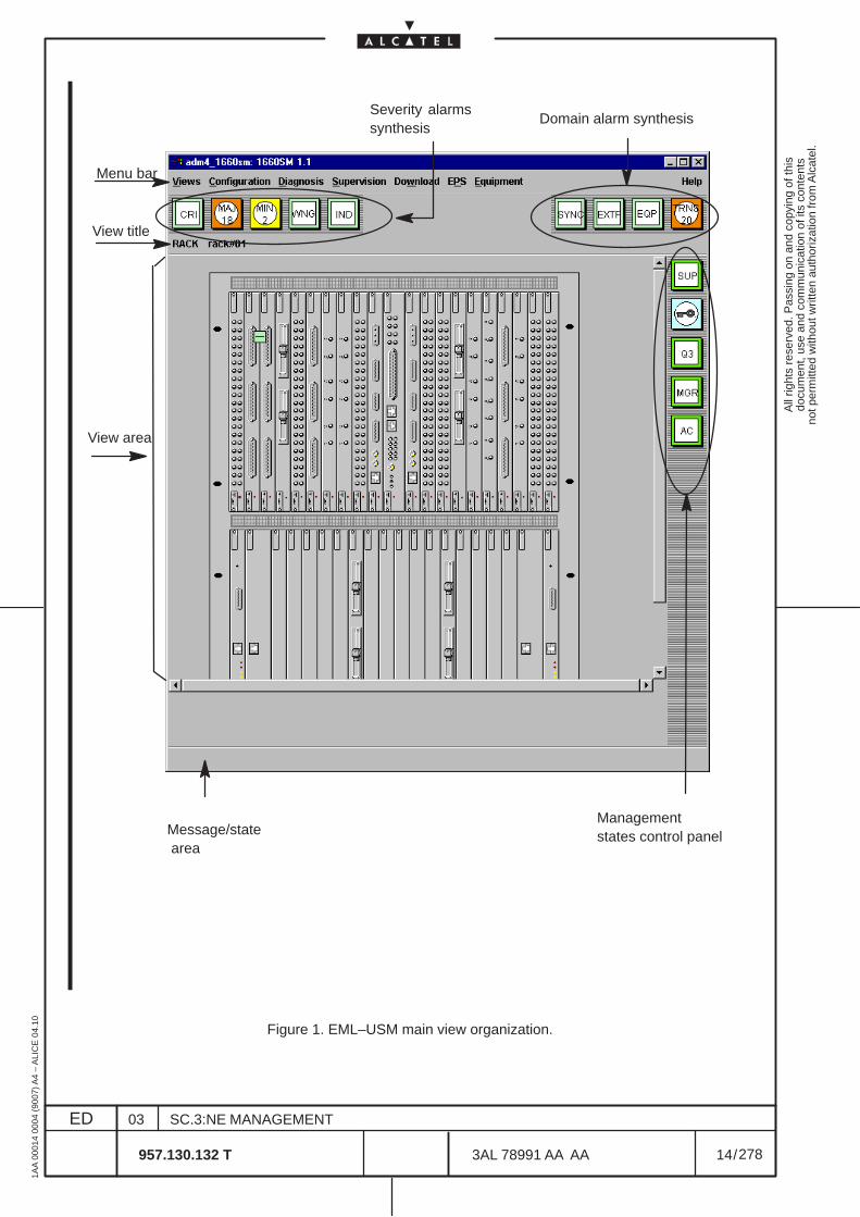
All
right
s re
serv
ed. P
assi
ng o
n an
d co
pyin
g of
this
docu
men
t, us
e an
d co
mm
unic
atio
n of
its
cont
ents
not p
erm
itted
with
out w
ritte
n au
thor
izat
ion
from
Alc
atel
.
ED
1AA
000
14 0
004
(900
7) A
4 –
ALI
CE
04.
10
14
03
957.130.132 T
SC.3:NE MANAGEMENT
/3AL 78991 AA AA
278
278
Severity alarmssynthesis
Message/state area
View area
View title
Domain alarm synthesis
Management states control panel
Menu bar
Figure 1. EML–USM main view organization.
All
right
s re
serv
ed. P
assi
ng o
n an
d co
pyin
g of
this
docu
men
t, us
e an
d co
mm
unic
atio
n of
its
cont
ents
not p
erm
itted
with
out w
ritte
n au
thor
izat
ion
from
Alc
atel
.
ED
1AA
000
14 0
004
(900
7) A
4 –
ALI
CE
04.
10
15
03
957.130.132 T
SC.3:NE MANAGEMENT
/3AL 78991 AA AA
278
278
2.2 Introduction on the EML–USM menu options
The menu bar allows to perform configuration and supervision functions on the Network Element.
This paragraph list all the menu options and then more details on the relevant contained entries.
For each of them the relevant operative function are briefly introduced and it is referred the paragraphswhere it is detailed or the introduction to the options of each menu inserted in next paragraphs of thischapter.
The flow charts of Figure 2. on page 27, Figure 3. on page 28 and Figure 4. on page 29 summarize themenu options.
From chapter 3 on details and operative information on the all the views are given. They are not presentedaccording the menu option sequence but according a functional subdivision.
In the menu bar there are permanent menu items always displayed. Staring from the left , the menus are:
– Permanent Menus
• Views (first column). See para.2.2.1 on page 17.
To navigate among the views and set TMN and OverHead parameters.
• Configuration (second column). See para.2.2.2 on page 18.
To set general configuration of the NE, set TMN and OverHead parameters and to show ormodify some parameters (performance monitoring, cross–connection).
• Diagnosis (third column). See para.2.2.3 on page 19.
To get information about the NE (alarms, performance monitoring, remote inventory).
• Supervision (fourth column). See para.2.2.4 on page 20.
To set the supervision states (i.e. Craft Terminal enabling).
• Download (fifth column). See chapter 19 on page 269.
To manage the NE software (download, MIB management).
• Help (last column).
To activate the help.

All
right
s re
serv
ed. P
assi
ng o
n an
d co
pyin
g of
this
docu
men
t, us
e an
d co
mm
unic
atio
n of
its
cont
ents
not p
erm
itted
with
out w
ritte
n au
thor
izat
ion
from
Alc
atel
.
ED
1AA
000
14 0
004
(900
7) A
4 –
ALI
CE
04.
10
16
03
957.130.132 T
SC.3:NE MANAGEMENT
/3AL 78991 AA AA
278
278
Further, in the menu bar there are other menus, presented as an alternative, only when a particular objector option is selected.
– Other Menus
• Equipment (seventh column). See chapter 9 on page 77
To manage the NE as a whole, setting the boards which compose it. From the Equipment viewthe Board view can be accessed.
• Board (seventh column). See chapter 10 on page 89.
To show the physical port available in a specific board. It is the entry point for the Port view.
• Transmission (sixth column). See chapter 14 on page 135.
It permits to show and set the Termination Point of the equipment, thus having an overview ofthe complete signal flow of the various port.The menu permits to define all the Cross Connections and manages the transmissionresources, setting the relevant configuration.Further access the Performance Monitoring and permits navigation to the Board view.
• Port (sixth column). See chapter 11 on page 95.
To set and show (detailed alarm view) the transmission resources referred to the Port.
• EPS (sixth column). See chapter 12 on page 113.
To manage the EPS protection, setting the relevant configuration.
• Synchronization (sixth column). See chapter 18 on page 251.
To show and modify synchronization parameters.
• External Points (sixth column). See chapter 6 on page 49.
To show and modify housekeeping (environmental) alarms.
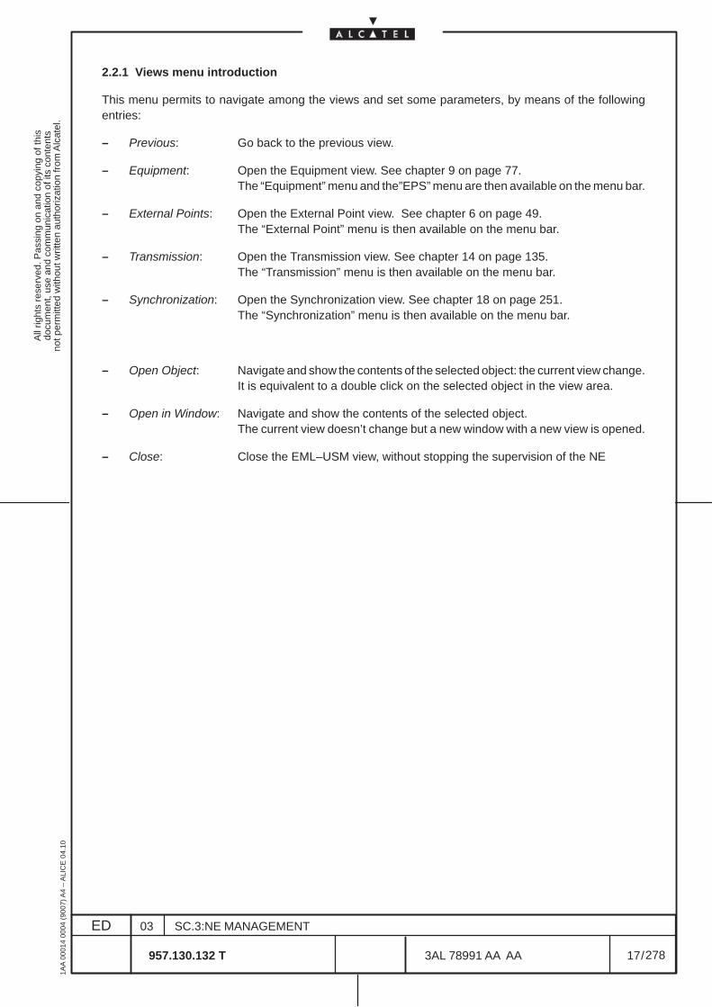
All
right
s re
serv
ed. P
assi
ng o
n an
d co
pyin
g of
this
docu
men
t, us
e an
d co
mm
unic
atio
n of
its
cont
ents
not p
erm
itted
with
out w
ritte
n au
thor
izat
ion
from
Alc
atel
.
ED
1AA
000
14 0
004
(900
7) A
4 –
ALI
CE
04.
10
17
03
957.130.132 T
SC.3:NE MANAGEMENT
/3AL 78991 AA AA
278
278
2.2.1 Views menu introduction
This menu permits to navigate among the views and set some parameters, by means of the followingentries:
– Previous: Go back to the previous view.
– Equipment: Open the Equipment view. See chapter 9 on page 77.The “Equipment” menu and the”EPS” menu are then available on the menu bar.
– External Points: Open the External Point view. See chapter 6 on page 49.The “External Point” menu is then available on the menu bar.
– Transmission: Open the Transmission view. See chapter 14 on page 135.The “Transmission” menu is then available on the menu bar.
– Synchronization: Open the Synchronization view. See chapter 18 on page 251.The “Synchronization” menu is then available on the menu bar.
– Open Object: Navigate and show the contents of the selected object: the current view change.It is equivalent to a double click on the selected object in the view area.
– Open in Window: Navigate and show the contents of the selected object.The current view doesn’t change but a new window with a new view is opened.
– Close: Close the EML–USM view, without stopping the supervision of the NE

All
right
s re
serv
ed. P
assi
ng o
n an
d co
pyin
g of
this
docu
men
t, us
e an
d co
mm
unic
atio
n of
its
cont
ents
not p
erm
itted
with
out w
ritte
n au
thor
izat
ion
from
Alc
atel
.
ED
1AA
000
14 0
004
(900
7) A
4 –
ALI
CE
04.
10
18
03
957.130.132 T
SC.3:NE MANAGEMENT
/3AL 78991 AA AA
278
278
2.2.2 Configuration menu introduction
This menu permits to set general configuration of the NE and to show or modify some parameters, bymeans of the following entries:
– Alarm Severities: Manage the Alarm Severity Assignment Profile.See para. 4.3.1.1 on page 39.
– Set Alarm severities: Send the Alarm Severity Assignment Profile to the selected objectSee para. 4.3.1.2 on page 42.
– Set SdhNe Alarm severities: Send the Alarm Severity Assignment Profile referred to theequipment level.See para. 4.3.1.2 on page 42.
– NE Time: Display and set the NE local time. See para. 4.2 on page 37.
– Performance: Manage the the Performance Monitoring domain.Used to define the PM parameters, opening the following menu options:
• Threshold table: See para.17.5 on page. 243.
– Set ACD level: See para.5.2 on page 48. Not operative
– Cross Connection Management: Manage the connection of the paths.See para.15.3 on page 187
– Loopback Management: Enter the loopback management. See para. 14.13 on page 162.Used to configure the loopback command for commissioning ormaintenance purposes.
– Comm/Routing: Enter the Communication and Routing management. See para. 8 on page 63.Used to define the parameters for NE and OS in the TMN, opening the followingmenu options:• Local configuration• OS Configuration• NTP Server Configuration• LAPD Configuration• Ethernet Configuration• RAP Configuration• MESA Configuration
– Overhead: Handle the operation on the Overhead bytes. See para.16 on page 219.Used to define the parameters in the following menu options:• OH Cross Connection• OH Phone Parameter• OH TP creation• OH TP deleting
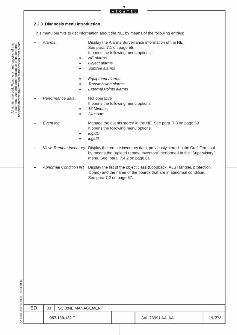
All
right
s re
serv
ed. P
assi
ng o
n an
d co
pyin
g of
this
docu
men
t, us
e an
d co
mm
unic
atio
n of
its
cont
ents
not p
erm
itted
with
out w
ritte
n au
thor
izat
ion
from
Alc
atel
.
ED
1AA
000
14 0
004
(900
7) A
4 –
ALI
CE
04.
10
19
03
957.130.132 T
SC.3:NE MANAGEMENT
/3AL 78991 AA AA
278
278
2.2.3 Diagnosis menu introduction
This menu permits to get information about the NE, by means of the following entries:
– Alarms: Display the Alarms Surveillance information of the NE.See para. 7.1 on page 55.It opens the following menu options:
• NE alarms• Object alarms• Subtree alarms
• Equipment alarms• Transmission alarms• External Points alarms
– Performance data: Not operativeIt opens the following menu options:
• 15 Minutes• 24 Hours
– Event log: Manage the events stored in the NE. See para. 7.3 on page 59It opens the following menu options:
• logld1• logld2
– View Remote Inventory: Display the remote inventory data, previously stored in the Craft Terminalby means the “upload remote inventory” performed in the “Supervisory”menu. See para 7.4.2 on page 61.
– Abnormal Condition list Display the list of the object class (Loopback, ALS Handler, protection board) and the name of the boards that are in abnormal condition.See para 7.2 on page 57.
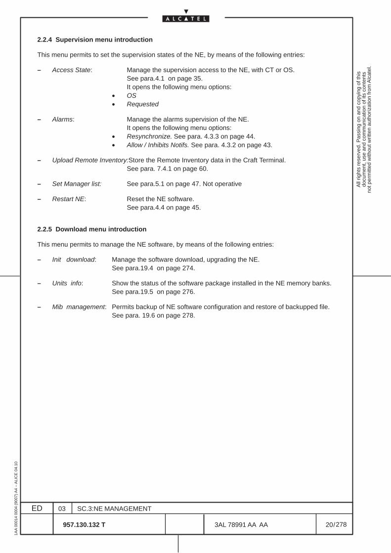
All
right
s re
serv
ed. P
assi
ng o
n an
d co
pyin
g of
this
docu
men
t, us
e an
d co
mm
unic
atio
n of
its
cont
ents
not p
erm
itted
with
out w
ritte
n au
thor
izat
ion
from
Alc
atel
.
ED
1AA
000
14 0
004
(900
7) A
4 –
ALI
CE
04.
10
20
03
957.130.132 T
SC.3:NE MANAGEMENT
/3AL 78991 AA AA
278
278
2.2.4 Supervision menu introduction
This menu permits to set the supervision states of the NE, by means of the following entries:
– Access State: Manage the supervision access to the NE, with CT or OS.See para.4.1 on page 35.It opens the following menu options:
• OS• Requested
– Alarms: Manage the alarms supervision of the NE.It opens the following menu options:
• Resynchronize. See para. 4.3.3 on page 44.• Allow / Inhibits Notifs. See para. 4.3.2 on page 43.
– Upload Remote Inventory:Store the Remote Inventory data in the Craft Terminal.See para. 7.4.1 on page 60.
– Set Manager list: See para.5.1 on page 47. Not operative
– Restart NE: Reset the NE software.See para.4.4 on page 45.
2.2.5 Download menu introduction
This menu permits to manage the NE software, by means of the following entries:
– Init download: Manage the software download, upgrading the NE.See para.19.4 on page 274.
– Units info: Show the status of the software package installed in the NE memory banks.See para.19.5 on page 276.
– Mib management: Permits backup of NE software configuration and restore of backupped file.See para. 19.6 on page 278.
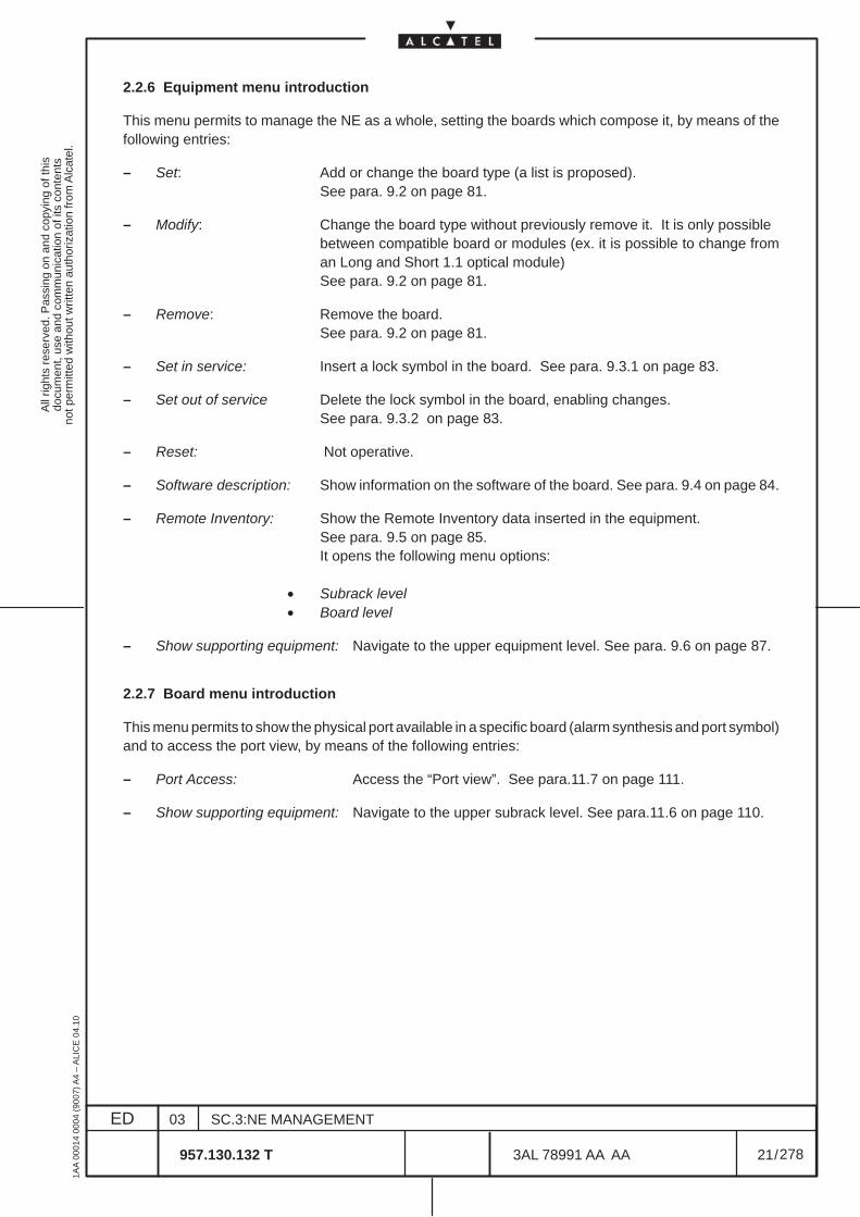
All
right
s re
serv
ed. P
assi
ng o
n an
d co
pyin
g of
this
docu
men
t, us
e an
d co
mm
unic
atio
n of
its
cont
ents
not p
erm
itted
with
out w
ritte
n au
thor
izat
ion
from
Alc
atel
.
ED
1AA
000
14 0
004
(900
7) A
4 –
ALI
CE
04.
10
21
03
957.130.132 T
SC.3:NE MANAGEMENT
/3AL 78991 AA AA
278
278
2.2.6 Equipment menu introduction
This menu permits to manage the NE as a whole, setting the boards which compose it, by means of thefollowing entries:
– Set: Add or change the board type (a list is proposed).See para. 9.2 on page 81.
– Modify: Change the board type without previously remove it. It is only possiblebetween compatible board or modules (ex. it is possible to change froman Long and Short 1.1 optical module)See para. 9.2 on page 81.
– Remove: Remove the board.See para. 9.2 on page 81.
– Set in service: Insert a lock symbol in the board. See para. 9.3.1 on page 83.
– Set out of service Delete the lock symbol in the board, enabling changes.See para. 9.3.2 on page 83.
– Reset: Not operative.
– Software description: Show information on the software of the board. See para. 9.4 on page 84.
– Remote Inventory: Show the Remote Inventory data inserted in the equipment.See para. 9.5 on page 85.It opens the following menu options:
• Subrack level• Board level
– Show supporting equipment: Navigate to the upper equipment level. See para. 9.6 on page 87.
2.2.7 Board menu introduction
This menu permits to show the physical port available in a specific board (alarm synthesis and port symbol)and to access the port view, by means of the following entries:
– Port Access: Access the “Port view”. See para.11.7 on page 111.
– Show supporting equipment: Navigate to the upper subrack level. See para.11.6 on page 110.
All
right
s re
serv
ed. P
assi
ng o
n an
d co
pyin
g of
this
docu
men
t, us
e an
d co
mm
unic
atio
n of
its
cont
ents
not p
erm
itted
with
out w
ritte
n au
thor
izat
ion
from
Alc
atel
.
ED
1AA
000
14 0
004
(900
7) A
4 –
ALI
CE
04.
10
22
03
957.130.132 T
SC.3:NE MANAGEMENT
/3AL 78991 AA AA
278
278
2.2.8 Port menu introduction
This menu permits to set and show the transmission resources (TP) referred to the Port, by means of theentries indicated in the following list.
The menu differs according the port type (SDH, PDH, HOA).
The “Port view” is reached by means the Equipment menu and Board view to check the detailed alarmspresented, but the available menu permits to configure the port (many setting options listed in the portmenu are common with the “Transmission” view).In these views are presented only the TP specific of the port.
It permits navigation to the Transmission view.
– TP configuration: Set parameters for the Overhead (Signal Label and Path Trace) onSynchronous TP’s.See para 14.6 on page 148.
– TP Threshold Configuration: Set B2 excessive BER and Signal Degraded parameter.See para 14.8 on page 153.
– PDH TP configuration: Set parameters for the Plesiochronous TP’s to use it as a timing reference.Only for PDH ports views. See para 14.7 on page 152.
– AU4 Concatenation: Only for SDH ports views. See para. 11.4 on page 99.
– Cross Connection: Manage the connection of the paths. See para.15 on page 173.It opens the following menu options:
• Cross Connection Management• Create Cross Connection• Modify Cross Connection
– POM / SUT configuration: Set parameters for POM/SUT TP’s. See para. 14.11 on page 156.Not available for PDH port.It opens the following menu options:
• Creation / Deletion• Configuration
– Show TP performance data: not operative.Not available for HOA port.It opens the following menu options:
• 15 minutes• 24 hours
– Performance: Set and show Performance Monitoring parameters and data.See chapter 17 on page 231.It opens the following menu options:
• Configure Monitoring• Display Current Data• Display History Data
– Loopback: Enter the loopback management. See para. 14.13 on page 162.Used to configure the loopback command for commissioning ormaintenance purposes:
• Port Loopback Configuration• Loopback management
All
right
s re
serv
ed. P
assi
ng o
n an
d co
pyin
g of
this
docu
men
t, us
e an
d co
mm
unic
atio
n of
its
cont
ents
not p
erm
itted
with
out w
ritte
n au
thor
izat
ion
from
Alc
atel
.
ED
1AA
000
14 0
004
(900
7) A
4 –
ALI
CE
04.
10
23
03
957.130.132 T
SC.3:NE MANAGEMENT
/3AL 78991 AA AA
278
278
– MSP Manage the Multiplex Section Protection of the NE. (Not operative)See Chapter 13 on page 123.Only for SDH ports view.It opens the following menu options:
• MSP Create• MSP Management• MSP Commands• MSP Delete
– Physical Media: Manage the physical setting of the TP of the ports. Not applicable to HOAport. See para.11.5 on page 101.It opens a menu which differs according the port type:
– SDH port:• ALS Management• Show Optical Configuration• TX Quality Configuration• Single Fiber Configuration• LAPD Configuration• Ms Configuration
– PDH port:• Line Length Configuration• HDSL Configuration• NT G703/704 Configuration• NT X21 Configuration
– Show supporting board: Navigate to the upper board level.See para.11.6 on page 110.
– Navigate to Transmission view: permit to show a complete overview about the signal flow, openingall TP’sSee para.11.7 on page 111
2.2.9 EPS menu introduction
This menu permits to manage the EPS protection, setting the relevant configuration, by means of thefollowing entries :
– Management: Set EPS protections. See para.12.2 on page 114.
– Configure: Set revertive / not revertive and WTR parameters. See para. 12.3 on page 119.
– Switch: Manage the EPS operator commands (Force, Manual, Lockout)See para.12.4 on page 121.
All
right
s re
serv
ed. P
assi
ng o
n an
d co
pyin
g of
this
docu
men
t, us
e an
d co
mm
unic
atio
n of
its
cont
ents
not p
erm
itted
with
out w
ritte
n au
thor
izat
ion
from
Alc
atel
.
ED
1AA
000
14 0
004
(900
7) A
4 –
ALI
CE
04.
10
24
03
957.130.132 T
SC.3:NE MANAGEMENT
/3AL 78991 AA AA
278
278
2.2.10 Transmission menu introduction
This menu permits to show and set the Termination Point of the equipment, thus having an overview ofthe complete signal flow of the various port.
The menu permits to define all the Cross Connections and manages the transmission resources, settingthe relevant configuration.
Further access the Performance Monitoring and manage Multiplex Section Protections and Loopbacksfunctions.
It permits navigation to the Port view.
The menu lists the following entries:
– Add TP: Search and add TP to the transmission view, than presented in the screen.See para.14.5 on page 141.
– Expand: Display the TP’s related to a selected TP. See para.14.15.1 on page 169.It opens the following menu options:
• Next level of lower TP• All lower TP• Next level of upper TP• All upper TP
– Hide: Remove the TP from the screen of the Transmission view.See para.14.15.2 on page 170.It opens the following menu options:
• Lower TP• Upper TP• Selected TP
– TP configuration: Set parameters for the Signal Label and Path trace.See para.14.6 on page 148.
– PDH TP configuration: Set parameters for the Plesiochronous TP’s to use it as timing reference.Only for PDH ports views. See para.14.7 on page 152.
– TP Threshold configuration: Set B2 Ex BER and Signal Degrade threshold.See para. 14.8 on page 153.
– Alarm Persistency Time To suppress oscillating alarms. See para.14.9 on page 154.
– Terminate TP: Terminate the AU4–CTP paths. See para.14.10 on page 155.
– Disterminate TP: Disterminate the AU4–CTP paths. See para.14.10 on page 155
– Cross Connection: Manage the connection of the paths. See para.15 on page 173.It opens the following menu options:
• Cross Connection Management• Create Cross Connection• Modify Cross Connection• Port Switch Over• Show Cross Connected TP’s
All
right
s re
serv
ed. P
assi
ng o
n an
d co
pyin
g of
this
docu
men
t, us
e an
d co
mm
unic
atio
n of
its
cont
ents
not p
erm
itted
with
out w
ritte
n au
thor
izat
ion
from
Alc
atel
.
ED
1AA
000
14 0
004
(900
7) A
4 –
ALI
CE
04.
10
25
03
957.130.132 T
SC.3:NE MANAGEMENT
/3AL 78991 AA AA
278
278
– POM / SUT configuration: Add or change the board type (a list is proposed).See para.14.11 on page 156It opens the following menu options:
• Creation / deletion• Configuration
– Performance: Set and show Performance Monitoring parameters and data.See chapter 17 on page 231.It opens the following menu options:
• Configure Monitoring• Display Current Data• Display History Data
– Structure TP’s: Define the structure of a selected TP (TU2, TU3, TU12, VC3/VC4, VC12)See para.14.12 on page 161.
– Loopback : Enter the loopback management. See para. 14.13 on page 162.Used to configure the loopback command for commissioning ormaintenance purposes:It opens the following menu options:
• Port Loopback Configuration• Loopback management
– Physical Media: Manage the TP physical setting. See para.14.14 on page 167.It opens the following menu options:
• ALS Management• Show Optical Configuration• TX Quality Configuration• Single Fiber Configuration• Extra traffic• Regeneration Section management• Line Length Configuration• Set Domain• HDSL Configuration• NT Configuration• X21 Configuration
– MSP Manage the Multiplex Section Protection of the NE.It opens the following menu options:
• MSP Create• MSP Management• MSP Commands• MSP Delete• NE MSP synthesis
– Show supported board: Navigate to the board supporting the selected TPSee para.14.15.3 on page 171.
– Navigate to Port view: Navigate to the port supporting the selected TPSee para.14.15.4 on page 172.
All
right
s re
serv
ed. P
assi
ng o
n an
d co
pyin
g of
this
docu
men
t, us
e an
d co
mm
unic
atio
n of
its
cont
ents
not p
erm
itted
with
out w
ritte
n au
thor
izat
ion
from
Alc
atel
.
ED
1AA
000
14 0
004
(900
7) A
4 –
ALI
CE
04.
10
26
03
957.130.132 T
SC.3:NE MANAGEMENT
/3AL 78991 AA AA
278
278
2.2.11 Synchronization menu introduction
This menu permits to set and show the Synchronization parameters and status, setting the relevantconfiguration, by means of the following entries :
– Timing Source Configuration: Set timing source priority and quality for the selected input reference.See para.18.2.3 on page 257.
– Protection Command: Manage commands (force, manual, lockout) for the selected timingreference. See para.18.2.4 on page 260.
– T0 Configuration: Enable/disable SSM and WTR on the T0 synchronization source.See para.18.2.5 on page 261.
– T4 Configuration: Enable/disable SSM, WTR and Squelch Criteria on the T4synchronization source. See para.18.2.5 on page 261.
– T0 TEST Configuration: Not used.
– SSU Configuration: Set NE single or with SSU. See para.18.2.6 on page 263.
– Remove Timing Reference See para.18.2.7 on page 264.
– Set T0 Equal T4 See para.18.2.8 on page 265.
– Remove T0 Equal T4 See para.18.2.8 on page 265.
– Transmitted SSM Quality Configuration: Set SSM quality transmitted on the selected T1 SDHtiming reference. See para.18.2.9 on page 266.
–
– Show Timing Source: Show the “port view” related to the selected timing reference.See para.18.2.10 on page 267.
2.2.12 External Points menu introduction
This menu permits to display and set the input/output environmental alarm (housekeeping alarm), bymeans of the following entries:
– Configuration: Set the input/output environmental alarm.See para. 6.2 on page 53.
– Display: Show the list of the input/output environmental alarm.See para. 6.1 on page 50.It opens the following menu options:
• Show external Input Points• Show external Output Points• Show all external Points
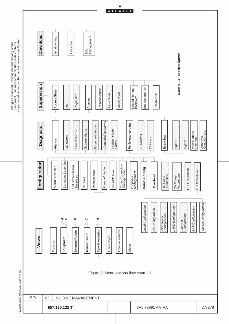
All
right
s re
serv
ed. P
assi
ng o
n an
d co
pyin
g of
this
docu
men
t, us
e an
d co
mm
unic
atio
n of
its
cont
ents
not p
erm
itted
with
out w
ritte
n au
thor
izat
ion
from
Alc
atel
.
ED
1AA
000
14 0
004
(900
7) A
4 –
ALI
CE
04.
10
27
03
957.130.132 T
SC.3:NE MANAGEMENT
/3AL 78991 AA AA
278
278
ËËËËËËËËËËËË
ËËËËËËËËËË
ËËËËËËËËËË
ÇÇÇÇÇÇÇÇÇÇÇÇ
ÇÇÇÇÇÇÇÇÇÇÇÇ
ÇÇÇÇÇÇÇÇÇÇÇÇ
ÇÇÇÇÇÇÇÇÇÇÇÇ
ÇÇÇÇÇÇÇÇÇÇÇÇ
ÇÇÇÇÇÇÇÇÇÇÇÇ
ÇÇÇÇÇÇÇÇÇÇÇÇ
ÇÇÇÇÇÇÇÇÇÇÇÇ
ÇÇÇÇÇÇÇÇÇÇÇÇ
ÇÇÇÇÇÇÇÇÇÇÇÇ
ËËËËËËËËËËËË
ËËËËËËËËËË
Vie
ws
Co
nfi
gu
rati
on
D
iag
no
sis
Su
per
visi
on
Do
wn
load
Pre
viou
s
Eq
uip
men
t
Ext
ern
al P
oin
ts
Tran
smis
sio
n
Syn
chro
niz
atio
n
Co
mm
/Ro
uti
ng
Ove
rhea
d
Ope
n O
bjec
t
Ope
n in
Win
dow
Clo
se
Loca
l Con
figur
atio
n
OS
Con
figur
atio
n
NT
P S
erve
r
LAP
D C
onfig
urat
ion
Eth
erne
t
RA
P C
onfig
urat
ion
ME
SA
Con
figur
atio
n
OH
Cro
ss
OH
TP
Cre
atio
n
OH
TP
Del
etin
g
Con
figur
atio
n
Con
figur
atio
n
Con
nect
ion
Ala
rm S
ever
ities
Set
Ala
rm S
ever
ities
NE
Tim
e
Per
form
ance
Set
AC
D le
vel
Cro
ss C
onne
ctio
nM
anag
emen
t
ÇÇÇÇÇÇÇÇÇÇÇÇ
Thr
esho
ld ta
ble
Ala
rms
ÇÇÇÇÇÇÇÇÇÇÇÇ
ÇÇÇÇÇÇÇÇÇÇÇÇ
ÇÇÇÇÇÇÇÇÇÇÇÇ
ÇÇÇÇÇÇÇÇÇÇÇÇ
ÇÇÇÇÇÇÇÇÇÇÇÇ
ÇÇÇÇÇÇÇÇÇÇÇÇ
NE
ala
rms
Obj
ect a
larm
s
Equ
ipm
ent a
larm
s
Tran
smis
sion
ala
rms
Ext
erna
l Poi
nts
Per
form
ance
dat
a ÇÇÇÇÇÇÇÇÇÇÇÇ
ÇÇÇÇÇÇÇÇÇÇÇÇ
15 M
inut
es
24 H
ours
Eve
nt
log
ÇÇÇÇÇÇÇÇÇÇÇÇ
ÇÇÇÇÇÇÇÇÇÇÇÇ
logl
d 1
logl
d 2
Vie
w R
emot
eIn
vent
ory
Sub
tree
ala
rms
alar
ms
Acc
ess
Sta
te
ÇÇÇÇÇÇÇÇÇÇ
ÇÇÇÇÇÇÇÇÇÇ
OS
Req
uest
ed
Ala
rms
ÇÇÇÇÇÇÇÇÇÇ
ÇÇÇÇÇÇÇÇÇÇÇÇÇÇÇ
Res
ynch
roni
ze
Allo
w N
otifs
Upl
oad
Rem
ote
Set
Man
ager
list
Inve
ntor
y
Init
dow
nloa
d
Uni
ts in
fo
Mib
Res
tart
NE
DCBA E
No
te: A
.....F
See
nex
t fi
gu
res
Abn
orm
al
Con
ditio
n Li
st
ÇÇÇÇÇÇÇÇÇÇ
Inhi
bit N
otifs
ÇÇÇÇÇÇÇÇÇÇÇÇ
Oh
Pho
neP
aram
eter
s
Man
agem
ent
Loop
back
Man
agem
ent
Sev
eriti
esS
et S
dhN
e A
larm
Figure 2. Menu options flow chart – 1
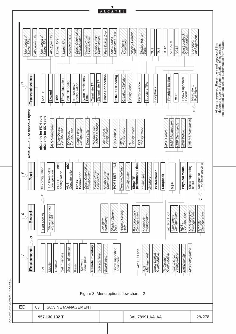
All
right
s re
serv
ed. P
assi
ng o
n an
d co
pyin
g of
this
docu
men
t, us
e an
d co
mm
unic
atio
n of
its
cont
ents
not p
erm
itted
with
out w
ritte
n au
thor
izat
ion
from
Alc
atel
.
ED
1AA
000
14 0
004
(900
7) A
4 –
ALI
CE
04.
10
28
03
957.130.132 T
SC.3:NE MANAGEMENT
/3AL 78991 AA AA
278
278
ÇÇÇÇÇÇÇÇÇÇ
ÇÇÇÇÇÇÇÇÇÇÇÇ
ËËËËËËËËËËËË
ËËËËËËËËËË
Eq
uip
men
tTr
ansm
issi
on
Set
Mod
ify
Rem
ove
Set
in s
ervi
ce
Set
out
of s
ervi
ce
Sof
twar
e
Rem
ote
Inve
nto
ry
Sho
w s
uppo
rtin
g
Add
TP
Exp
and
Hid
e
Res
et
desc
riptio
n
equi
pmen
t
Sub
rack
leve
l
Boa
rd le
vel
ËËËËËËËËËË P
ort A
cces
s
Sho
w s
uppo
rtin
g
Bo
ard
equi
pmen
t
ÇÇÇÇÇÇÇÇÇÇÇÇ
Nex
t Lev
el o
fLo
wer
TP
sÇÇÇÇÇÇÇÇÇÇÇÇ
Nex
t Lev
el o
f
ÇÇÇÇÇÇÇÇÇÇÇÇ
All
Low
er T
Ps
ÇÇÇÇÇÇÇÇÇÇÇÇ
All
Upp
er T
Ps
Upp
er T
Ps
ÇÇÇÇÇÇÇÇÇÇÇÇ
Low
er T
Ps
ÇÇÇÇÇÇ
Upp
er T
Ps
ÇÇÇÇÇÇ
Sel
ecte
d T
Ps
TP
con
figur
atio
n
PD
H T
P c
onfig
.
Ala
rm P
ersi
sten
cyTi
me
Cro
ss C
on
nec
tio
n
ÇÇÇÇÇÇÇÇÇÇÇÇ
Cro
ss C
onne
ctio
nM
anag
emen
t
ÇÇÇÇÇÇÇÇÇÇÇÇ
Cre
ate
Cro
ss
Con
nect
ions
ÇÇÇÇÇÇÇÇÇÇÇÇ
Mod
ify C
ross
Con
nect
ions
ÇÇÇÇÇÇÇÇÇÇÇÇÇÇÇÇÇÇ
Sho
w C
ross
C
onne
cted
TP
s
ÇÇÇÇÇÇÇÇÇÇÇÇ
Por
t Sw
itch
Ove
r
PO
M /
SU
T c
on
fig
.
ÇÇÇÇÇÇÇÇÇÇ
ÇÇÇÇÇÇÇÇÇÇC
reat
ion
/ Del
etio
n
Con
figur
atio
n
Per
form
ance
Str
uctu
re T
Ps
ÇÇÇÇÇÇÇÇÇÇÇÇ
Sho
w O
ptic
al
ÇÇÇÇÇÇ
ALS
Man
agem
ent
Con
figur
atio
n
ÇÇÇÇÇÇÇÇÇÇÇÇÇÇÇÇÇÇ
TX
Qua
lity
Con
figur
atio
n
ÇÇÇÇÇÇÇÇÇÇÇÇ
Sin
gle
Fib
erC
onfig
urat
ion
ÇÇÇÇÇÇÇÇÇÇÇÇ
Ext
ra tr
affic
ÇÇÇÇÇÇÇÇÇÇÇÇ
Reg
ener
atio
n S
ectio
n m
anag
e
ÇÇÇÇÇÇÇÇÇÇÇÇ
NE
MS
P s
ynth
esisÇÇ
ÇÇÇÇÇÇÇÇÇÇ
Line
Len
ght
Con
figur
atio
n
Sho
w S
uppo
rted
Boa
rds
Nav
igat
e to
Por
t Vie
w
Ph
ysic
al M
edia
:
ÇÇÇÇÇÇÇÇÇÇS
how
Opt
ical
Con
figur
atio
n
ÇÇÇÇÇÇÇÇÇÇA
LSM
anag
emen
t
ÇÇÇÇÇÇÇÇÇÇT
x Q
ualit
y C
onfig
urat
ion
ÇÇÇÇÇÇÇÇÇÇÇÇ
MS
P M
anag
emen
t
MS
P c
omm
ands
ÇÇÇÇÇÇÇÇÇÇÇÇ
Por
t Loo
pbac
kC
onfig
urat
ion
ÇÇÇÇÇÇÇÇÇÇÇÇ
Loop
back
man
agem
ent
TP
con
figur
atio
n
Cro
ssC
on
nec
tio
n
with
SD
H p
ort ÇÇ
ÇÇÇÇÇÇÇÇL
AP
D c
onfig
.
with
PD
H p
ort
ÇÇÇÇÇÇÇÇÇÇÇÇÇÇÇÇÇÇ
Line
Len
ght
Con
figur
atio
n
ÇÇÇÇÇÇÇÇÇÇÇÇ
Por
t Loo
pbac
kC
onfig
urat
ion
ÇÇÇÇÇÇÇÇÇÇÇÇ
Loop
back
m
anag
emen
t
AU
4C
onca
tena
tion
PO
M /
SU
T
PD
H T
Pco
nfig
urat
ion
ÇÇÇÇÇÇÇÇÇÇÇÇ
Cro
ss C
onne
ctio
nM
anag
emen
t
ÇÇÇÇÇÇÇÇÇÇÇÇ
Cre
ate
Cro
ss
Con
nect
ion
ÇÇÇÇÇÇÇÇÇÇÇÇÇÇÇÇÇÇ
Mod
ify C
ross
Con
nect
ion
Sh
ow
TP
per
form
ance
dat
a ÇÇÇÇÇÇ
15 m
inut
es
ÇÇÇÇÇÇ
24 h
ours
ÇÇÇÇÇÇÇÇÇÇÇÇ
Per
form
ance
Con
figur
eM
onito
ring
ÇÇÇÇÇÇÇÇÇÇÇÇ
Dis
play
Cur
rent
Dat
a
ÇÇÇÇÇÇÇÇÇÇÇÇ
Dis
play
His
tory
Dat
a
Nav
igat
e to
Tran
smis
sion
vie
w
ÇÇÇÇÇÇÇÇÇÇÇÇ
Con
figur
eM
onito
ring
ÇÇÇÇÇÇÇÇÇÇÇÇ
Dis
play
Cur
rent
Dat
a
ÇÇÇÇÇÇÇÇÇÇÇÇÇÇÇÇÇÇ
Dis
play
His
tory
Dat
a
Ph
ysic
al M
edia
:
ÇÇÇÇÇÇÇÇÇÇS
ingl
e F
iber
Con
figur
atio
n
Sho
w s
uppo
rtin
gbo
ard
AG
C
F
F
G
ËËËËËËËËËËËË
Po
rtF
No
te: A
.....F
See
pre
vio
us
fig
ure
TP
Thr
esho
lds
conf
igur
atio
n
ÇÇÇÇÇÇÇÇÇÇÇÇ
nb
2
nb
2
nb
1
nb
1: o
nly
fo
r P
DH
po
rt
nb
2: o
nly
fo
r S
DH
po
rt
MS
P C
omm
ands
Lo
op
bac
k
Lo
op
bac
k
ÇÇÇÇÇÇÇÇÇÇÇÇ
Set
Dom
ain
ÇÇÇÇÇÇÇÇÇÇÇÇ
ÇÇÇÇÇÇÇÇÇÇÇÇ
MS
PM
SP
C
Cre
atio
n / d
elet
ion
Con
figur
atio
n
TP
Thr
esho
ldC
onfig
urat
ion
Term
inat
e T
P
Dis
tern
inat
e T
P
TU
2
TU
3
TU
12
VC
3/V
C4
VC
12
ÇÇÇÇÇÇÇÇÇÇÇÇ
MS
P C
reat
e
ÇÇÇÇÇÇÇÇÇÇÇÇ
MS
P D
elet
e
ÇÇÇÇÇÇÇÇÇÇM
s C
onfig
urat
ion
ÇÇÇÇÇÇÇÇÇÇÇÇ
HD
SL
Con
figur
atio
n
ÇÇÇÇÇÇÇÇÇÇÇÇÇÇÇÇÇÇ
NT
G70
3/G
704
Con
figur
atio
n
ÇÇÇÇÇÇÇÇÇÇÇÇ
NT
X21
C
onfig
urat
ion
ÇÇÇÇÇÇÇÇÇÇÇÇ
HD
SL
Con
figur
atio
nÇÇÇÇÇÇÇÇÇÇÇÇÇÇÇÇÇÇ
NT
C
onfig
urat
ion
ÇÇÇÇÇÇÇÇÇÇÇÇ
X21
C
onfig
urat
ion
Figure 3. Menu options flow chart – 2
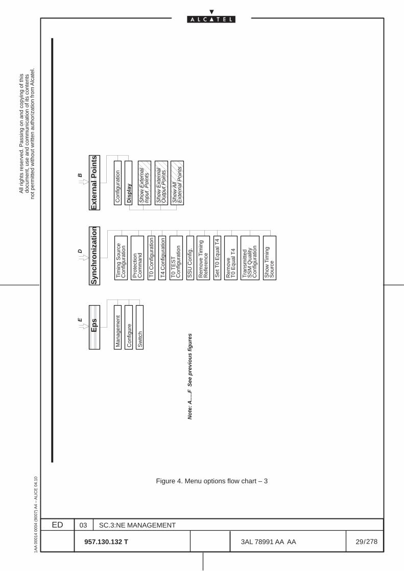
All
right
s re
serv
ed. P
assi
ng o
n an
d co
pyin
g of
this
docu
men
t, us
e an
d co
mm
unic
atio
n of
its
cont
ents
not p
erm
itted
with
out w
ritte
n au
thor
izat
ion
from
Alc
atel
.
ED
1AA
000
14 0
004
(900
7) A
4 –
ALI
CE
04.
10
29
03
957.130.132 T
SC.3:NE MANAGEMENT
/3AL 78991 AA AA
278
278
ËËËËËËËËËË
Ep
s
Man
agem
ent
Con
figur
e
Sw
itch
ËËËËËËËËËËËËËË
Syn
chro
niz
atio
n
T0
Con
figur
atio
n
T4
Con
figur
atio
n
SS
U C
onfig
.
Set
T0
Equ
al T
4
Tim
ing
Sou
rce
Con
figur
atio
n
Pro
tect
ion
Com
man
d
T0
TE
ST
Con
figur
atio
n
Rem
ove
Tim
ing
Ref
eren
ce
Tran
smitt
edS
SM
Qua
lity
Con
figur
atio
n
Sho
w T
imin
gS
ourc
e
ËËËËËËËËËËËËËË
Ext
ern
al P
oin
ts
Con
figur
atio
n
Dis
pla
y
ÇÇÇÇÇÇÇÇÇÇ
Sho
w E
xter
nal
Inpu
t P
oint
s
ÇÇÇÇÇÇÇÇÇÇÇÇÇÇÇ
Sho
w E
xter
nal
Out
put P
oint
sÇÇÇÇÇÇÇÇÇÇ
Sho
w A
llE
xter
nal P
oint
s
Rem
ove
T0
Equ
al T
4
ED
B
No
te: A
.....F
See
pre
vio
us
fig
ure
s
Figure 4. Menu options flow chart – 3

All
right
s re
serv
ed. P
assi
ng o
n an
d co
pyin
g of
this
docu
men
t, us
e an
d co
mm
unic
atio
n of
its
cont
ents
not p
erm
itted
with
out w
ritte
n au
thor
izat
ion
from
Alc
atel
.
ED
1AA
000
14 0
004
(900
7) A
4 –
ALI
CE
04.
10
30
03
957.130.132 T
SC.3:NE MANAGEMENT
/3AL 78991 AA AA
278
278
2.3 Advices on Navigation principles
Navigation rules are the same for all the NE using the same Craft Terminal Info Model.
This general rules are described in the “Basic Craft Terminal Operator Handbook”.
In this paragraphs are instead inserted menu options typical for this Ne involved in Navigation and exampleof Navigation.
To reach a particular view of the NE there are several ways (navigation is also possible mixing the differentways):
• double click on the selected object
• select the object and use the Open object or Open in Window option of the View pull downmenu
• use the Menu option tree structure. The View pull down menu permits to show the followingmenus:
– Equipment– Transmission– Synchronization– External Points
The menu structure permits to open the same window following several menu paths.
EXAMPLE: to obtain the “Create Cross Connection” window:
– First navigation path:Open View – Transmission pull down menuOpen Transmission – Cross Connection – Cross Connection Management pull downmenuSelect Create option in the presented window
– Second navigation path:Open View – Equipment pull down menuDouble click on Rack/Subrack/BoardSelect the Board to access the Board viewOpen Board – Port Access pull down menuOpen Port – Cross Connection – Create Cross Connection pull down menu
– Third navigation path:Open Configuration – Cross Connection Management pull down menuSelect Create option in the presented window
The menu structure also permits to pass from a view menu to another (i.e. from “port view” to”board view”or to “transmission view”) thus facilitating the operators activity.
All
right
s re
serv
ed. P
assi
ng o
n an
d co
pyin
g of
this
docu
men
t, us
e an
d co
mm
unic
atio
n of
its
cont
ents
not p
erm
itted
with
out w
ritte
n au
thor
izat
ion
from
Alc
atel
.
ED
1AA
000
14 0
004
(900
7) A
4 –
ALI
CE
04.
10
31
03
957.130.132 T
SC.3:NE MANAGEMENT
/3AL 78991 AA AA
278
278
Views Navigation
The first level of the “Equipment view” representation will be displayed directly into the current window,immediately after the NE login. (See Figure 1. on page 14).The Equipment view enables a fast navigation through all levels of the equipment hierarchy.Navigation is done from higher to lower levels. The NE hierarchy is generally organized in the followingway: rack>subrack > board > port > TP.
The navigation through different levels of the NE hierarchy is performed by double clicking on the objects:(see also para 9.1, pg. 77)
• the first level shows the rack level of the Equipment view (see Figure 1. on page 14);• by double clicking on a Equipment body, the subrack level of the Equipment view can be
reached.• further, by double clicking on a board body , the board level of the Equipment view can be
reached.• further, by double clicking on a port body contained in the board, the port level of the Equipment
view can be reached. The port view displays the inner TPs.• it is possible to go back to the upper level of representation by pressing the <ESC> key on the
keyboard; or to go back to the previous view, by selecting the Previous option from the Viewsmenu.
N.B. Selecting in the first level of the Equipment view ( rack level, Figure 1. on page 14 ) the Showsupporting equipment option from the Equipment menu, the Equipment level view ispresented;
All
right
s re
serv
ed. P
assi
ng o
n an
d co
pyin
g of
this
docu
men
t, us
e an
d co
mm
unic
atio
n of
its
cont
ents
not p
erm
itted
with
out w
ritte
n au
thor
izat
ion
from
Alc
atel
.
ED
1AA
000
14 0
004
(900
7) A
4 –
ALI
CE
04.
10
32
03
957.130.132 T
SC.3:NE MANAGEMENT
/3AL 78991 AA AA
278
278

All
right
s re
serv
ed. P
assi
ng o
n an
d co
pyin
g of
this
docu
men
t, us
e an
d co
mm
unic
atio
n of
its
cont
ents
not p
erm
itted
with
out w
ritte
n au
thor
izat
ion
from
Alc
atel
.
ED
1AA
000
14 0
004
(900
7) A
4 –
ALI
CE
04.
10
33
03
957.130.132 T
SC.3:NE MANAGEMENT
/3AL 78991 AA AA
278
278
3 NE MANAGEMENT SUPERVISION
This chapter is dedicated to the NE states and NE access.
3.1 NE management states
The elementary building blocks of any telecommunication network are the Network Elements (NEs).
Operating with the Craft Terminal the NE can present different management states according to thecondition of the connection (supervision, local access, connection state, etc). Also general Alarm statusare presented.Management states are present at Network Element Synthesis view level and at USM–EML view level.All the information referred to the management states are inserted in the Basic Craft Terminal Operator’sHandbook.Any disruption in the communication link between the CT and the NE results in an update of themanagement states when the CT has detected the communication failure.
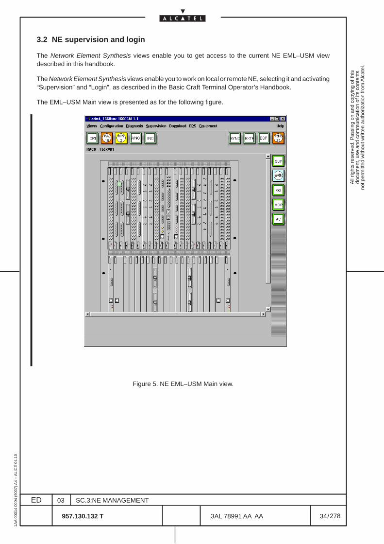
All
right
s re
serv
ed. P
assi
ng o
n an
d co
pyin
g of
this
docu
men
t, us
e an
d co
mm
unic
atio
n of
its
cont
ents
not p
erm
itted
with
out w
ritte
n au
thor
izat
ion
from
Alc
atel
.
ED
1AA
000
14 0
004
(900
7) A
4 –
ALI
CE
04.
10
34
03
957.130.132 T
SC.3:NE MANAGEMENT
/3AL 78991 AA AA
278
278
3.2 NE supervision and login
The Network Element Synthesis views enable you to get access to the current NE EML–USM viewdescribed in this handbook.
The Network Element Synthesis views enable you to work on local or remote NE, selecting it and activating“Supervision” and “Login”, as described in the Basic Craft Terminal Operator’s Handbook.
The EML–USM Main view is presented as for the following figure.
Figure 5. NE EML–USM Main view.
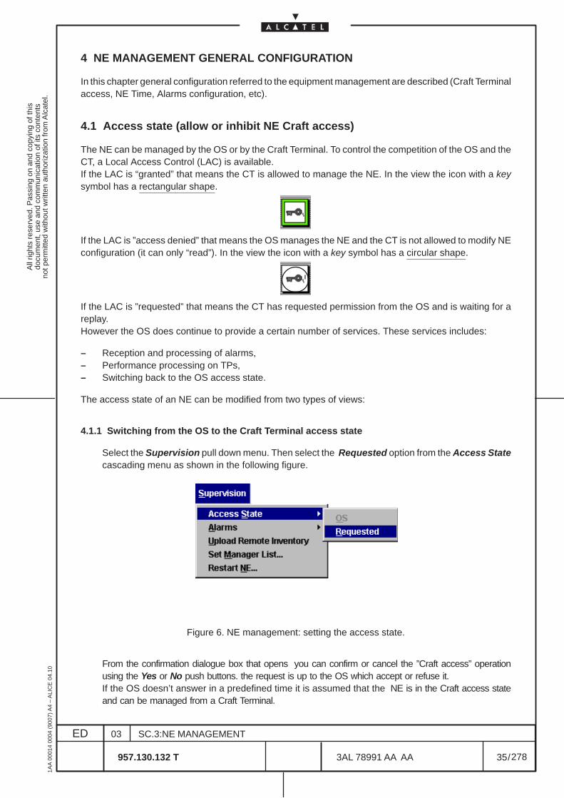
All
right
s re
serv
ed. P
assi
ng o
n an
d co
pyin
g of
this
docu
men
t, us
e an
d co
mm
unic
atio
n of
its
cont
ents
not p
erm
itted
with
out w
ritte
n au
thor
izat
ion
from
Alc
atel
.
ED
1AA
000
14 0
004
(900
7) A
4 –
ALI
CE
04.
10
35
03
957.130.132 T
SC.3:NE MANAGEMENT
/3AL 78991 AA AA
278
278
4 NE MANAGEMENT GENERAL CONFIGURATION
In this chapter general configuration referred to the equipment management are described (Craft Terminalaccess, NE Time, Alarms configuration, etc).
4.1 Access state (allow or inhibit NE Craft access)
The NE can be managed by the OS or by the Craft Terminal. To control the competition of the OS and theCT, a Local Access Control (LAC) is available.If the LAC is “granted” that means the CT is allowed to manage the NE. In the view the icon with a keysymbol has a rectangular shape.
If the LAC is ”access denied” that means the OS manages the NE and the CT is not allowed to modify NEconfiguration (it can only “read”). In the view the icon with a key symbol has a circular shape.
If the LAC is ”requested” that means the CT has requested permission from the OS and is waiting for areplay.However the OS does continue to provide a certain number of services. These services includes:
– Reception and processing of alarms,– Performance processing on TPs,– Switching back to the OS access state.
The access state of an NE can be modified from two types of views:
4.1.1 Switching from the OS to the Craft Terminal access state
Select the Supervision pull down menu. Then select the Requested option from the Access Statecascading menu as shown in the following figure.
Figure 6. NE management: setting the access state.
From the confirmation dialogue box that opens you can confirm or cancel the ”Craft access” operationusing the Yes or No push buttons. the request is up to the OS which accept or refuse it.If the OS doesn’t answer in a predefined time it is assumed that the NE is in the Craft access stateand can be managed from a Craft Terminal.
All
right
s re
serv
ed. P
assi
ng o
n an
d co
pyin
g of
this
docu
men
t, us
e an
d co
mm
unic
atio
n of
its
cont
ents
not p
erm
itted
with
out w
ritte
n au
thor
izat
ion
from
Alc
atel
.
ED
1AA
000
14 0
004
(900
7) A
4 –
ALI
CE
04.
10
36
03
957.130.132 T
SC.3:NE MANAGEMENT
/3AL 78991 AA AA
278
278
4.1.2 Switching from the Craft Terminal access state back to the OS access state
Select the Supervision pull down menu. Then select the OS... option from the Access Statecascading menu in Figure 6. From the confirmation dialogue box that opens you can confirm or cancel the ”OS access” operation.The NE is now managed by the OS.
N.B. The key symbol icon on the management states of the NE view, indicates whether the NE ismanaged by a craft terminal or by the OS.
N.B. Local Craft Terminal access is denied on recovery phase after a loss of communication of theNE. When communication is lost with the NE, the OS automatically recovers the communicationand put the state that was set before the loss of communication (therefore the Craft Terminalaccess can be denied or granted).
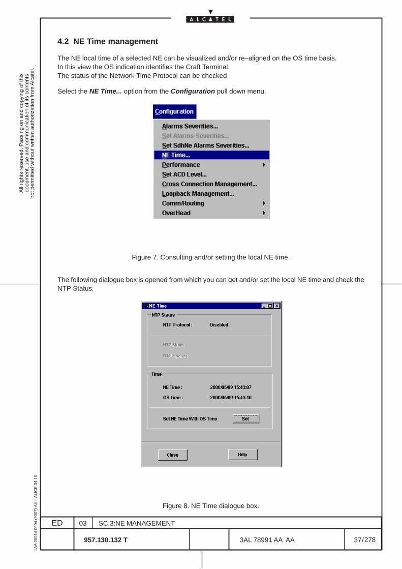
All
right
s re
serv
ed. P
assi
ng o
n an
d co
pyin
g of
this
docu
men
t, us
e an
d co
mm
unic
atio
n of
its
cont
ents
not p
erm
itted
with
out w
ritte
n au
thor
izat
ion
from
Alc
atel
.
ED
1AA
000
14 0
004
(900
7) A
4 –
ALI
CE
04.
10
37
03
957.130.132 T
SC.3:NE MANAGEMENT
/3AL 78991 AA AA
278
278
4.2 NE Time management
The NE local time of a selected NE can be visualized and/or re–aligned on the OS time basis.In this view the OS indication identifies the Craft Terminal.The status of the Network Time Protocol can be checked
Select the NE Time... option from the Configuration pull down menu.
Figure 7. Consulting and/or setting the local NE time.
The following dialogue box is opened from which you can get and/or set the local NE time and check theNTP Status.
Figure 8. NE Time dialogue box.

All
right
s re
serv
ed. P
assi
ng o
n an
d co
pyin
g of
this
docu
men
t, us
e an
d co
mm
unic
atio
n of
its
cont
ents
not p
erm
itted
with
out w
ritte
n au
thor
izat
ion
from
Alc
atel
.
ED
1AA
000
14 0
004
(900
7) A
4 –
ALI
CE
04.
10
38
03
957.130.132 T
SC.3:NE MANAGEMENT
/3AL 78991 AA AA
278
278
The following fields are available:
– NTP Status section (read only) with the following parameters:
• NTP protocolIt can be enabled (in the NTP Server Configuration option at para 8.5 on page 70) or disabledor empty (greyed).
• NTP Main and NTP SpareIt displays the status of the Main and Spare NTP: reachable or unreachable.
– Time section with the following data:
• NE Time and OS TimeIt displays (read only) the time of the Network Element and of the OS (Craft Terminal).
• Set NE Time With OS TimeIt permits to align the NE time with the time of the Craft Terminal.
Two different operative conditions can be defined:
– NTP protocol enabledIn this case, NTP Main and NTP Spare will be reachable or unreachable. When both are reachablethe NE uses the Main.The Set NE Time With OS Time message is not operative and the user cannot set manually the NETime.
– NTP protocol disabledIn this case, the NTP Main and NTP Spare are empty (greyed); the Set NE Time With OS Timemessage is operative and the user can set manually the NE Time (i.e. change the NE time with theTime of the Craft Terminal).
If you do not want to set the NE local time, click on the Close push button to close the dialogue box.
To re–align the NE time on the OS time basis click in the Set NE Time With OS Time radio button and eitherclick on the Apply push button to validate or on the Close push button to cancel and close the dialoguebox. The OS time comes from the PC date configuration which corresponds to the legal GMT time.
N.B. When the NTP is not present, the OS system re–aligns the time of all supervised NEsperiodically and automatically with a configured periodicity. This periodicity is common for allthe NEs.If you set the NE time, you will force the change, with an immediate effect on the NE. Howeverit will not have any effect on the periodic and automatic mechanism.
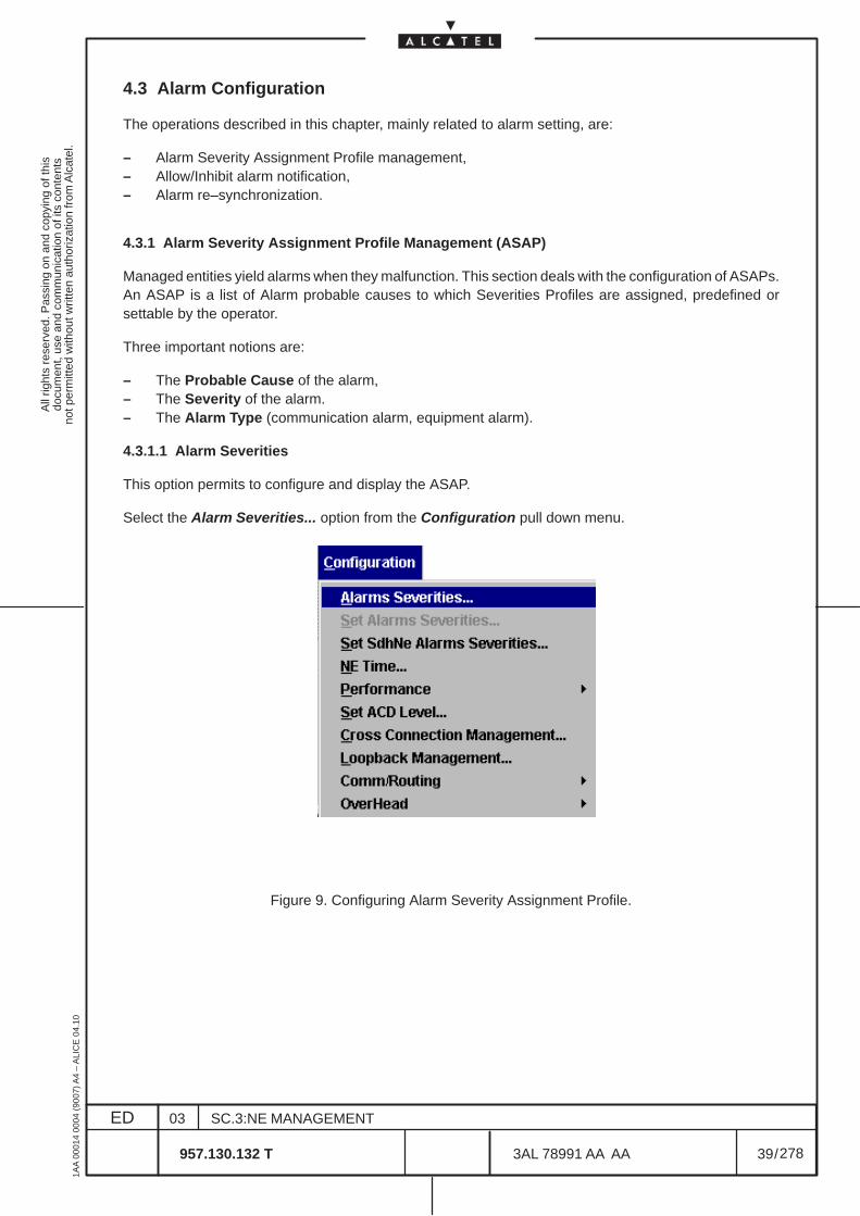
All
right
s re
serv
ed. P
assi
ng o
n an
d co
pyin
g of
this
docu
men
t, us
e an
d co
mm
unic
atio
n of
its
cont
ents
not p
erm
itted
with
out w
ritte
n au
thor
izat
ion
from
Alc
atel
.
ED
1AA
000
14 0
004
(900
7) A
4 –
ALI
CE
04.
10
39
03
957.130.132 T
SC.3:NE MANAGEMENT
/3AL 78991 AA AA
278
278
4.3 Alarm Configuration
The operations described in this chapter, mainly related to alarm setting, are:
– Alarm Severity Assignment Profile management,– Allow/Inhibit alarm notification,– Alarm re–synchronization.
4.3.1 Alarm Severity Assignment Profile Management (ASAP)
Managed entities yield alarms when they malfunction. This section deals with the configuration of ASAPs.An ASAP is a list of Alarm probable causes to which Severities Profiles are assigned, predefined orsettable by the operator.
Three important notions are:
– The Probable Cause of the alarm,– The Severity of the alarm.– The Alarm Type (communication alarm, equipment alarm).
4.3.1.1 Alarm Severities
This option permits to configure and display the ASAP.
Select the Alarm Severities... option from the Configuration pull down menu.
Figure 9. Configuring Alarm Severity Assignment Profile.
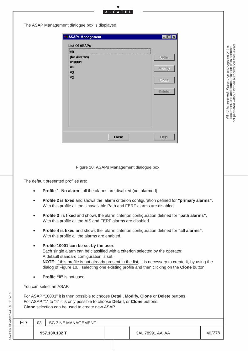
All
right
s re
serv
ed. P
assi
ng o
n an
d co
pyin
g of
this
docu
men
t, us
e an
d co
mm
unic
atio
n of
its
cont
ents
not p
erm
itted
with
out w
ritte
n au
thor
izat
ion
from
Alc
atel
.
ED
1AA
000
14 0
004
(900
7) A
4 –
ALI
CE
04.
10
40
03
957.130.132 T
SC.3:NE MANAGEMENT
/3AL 78991 AA AA
278
278
The ASAP Management dialogue box is displayed.
Figure 10. ASAPs Management dialogue box.
The default presented profiles are:
• Profile 1 No alarm : all the alarms are disabled (not alarmed).
• Profile 2 is fixed and shows the alarm criterion configuration defined for ”primary alarms”.With this profile all the Unavailable Path and FERF alarms are disabled.
• Profile 3 is fixed and shows the alarm criterion configuration defined for ”path alarms”.With this profile all the AIS and FERF alarms are disabled.
• Profile 4 is fixed and shows the alarm criterion configuration defined for ”all alarms”.With this profile all the alarms are enabled.
• Profile 10001 can be set by the user.Each single alarm can be classified with a criterion selected by the operator.A default standard configuration is set.NOTE: if this profile is not already present in the list, it is necessary to create it, by using thedialog of Figure 10. , selecting one existing profile and then clicking on the Clone button.
• Profile “0” is not used.
You can select an ASAP.
For ASAP “10001” it is then possible to choose Detail, Modify, Clone or Delete buttons.For ASAP “1” to “4” it is only possible to choose Detail, or Clone buttons.Clone selection can be used to create new ASAP.
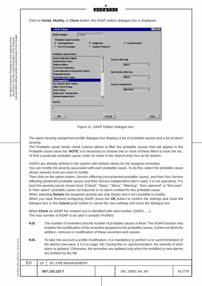
All
right
s re
serv
ed. P
assi
ng o
n an
d co
pyin
g of
this
docu
men
t, us
e an
d co
mm
unic
atio
n of
its
cont
ents
not p
erm
itted
with
out w
ritte
n au
thor
izat
ion
from
Alc
atel
.
ED
1AA
000
14 0
004
(900
7) A
4 –
ALI
CE
04.
10
41
03
957.130.132 T
SC.3:NE MANAGEMENT
/3AL 78991 AA AA
278
278
Click on Detail, Modify, or Clone button, the ASAP edition dialogue box is displayed.
Figure 11. ASAP Edition dialogue box.
The alarm severity assignment profile dialogue box displays a list of probable causes and a list of alarmseverity.The Probable cause family check buttons allows to filter the probable causes that will appear in theProbable cause name list. NOTE: it is necessary to choose one or more of these filters to have the list.To find a particular probable cause, enter its name in the Search entry box at the bottom.
ASAPs are already defined in the system with default values for the assigned severities.You can modify the severity associated with each probable cause. To do this, select the probable causewhose severity level you wish to modify.Then click on the option button: Service Affecting (not protected probable cause), and then Non ServiceAffecting (protected probable cause) and then Service Independent (don’t used, it is not operative). Foreach the severity can be chosen from ”Critical”, ”Major”, ”Minor”, ”Warning”, ”Non–alarmed” or “Not used”.A ”Non–alarm” probable cause corresponds to no alarm emitted for this probable cause.When selecting Details the assigned severity are only shown and it isn’t possible to modify.When you have finished configuring ASAP, press the OK button to confirm the settings and close thedialogue box or the Cancel push button to cancel the new settings and close the dialogue box.
When Clone an ASAP the created one is identified with next number (10002, ....).The max number of ASAP is six (don’t consider Profile0)
N.B. The number of severities and the number of probable causes is fixed. The ASAP function onlyenables the modification of the severities assigned to the probable causes, it does not allow theaddition, removal or modification of these severities and causes.
N.B. To take into account a profile modification, it is mandatory to perform a re–synchronization ofthe alarms (see para. 4.3.3 on page. 44). During this re–synchronization, the severity of eachalarm is updated. Otherwise, the severities are updated only when the modified or new alarmsare emitted by the NE.
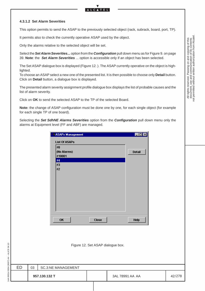
All
right
s re
serv
ed. P
assi
ng o
n an
d co
pyin
g of
this
docu
men
t, us
e an
d co
mm
unic
atio
n of
its
cont
ents
not p
erm
itted
with
out w
ritte
n au
thor
izat
ion
from
Alc
atel
.
ED
1AA
000
14 0
004
(900
7) A
4 –
ALI
CE
04.
10
42
03
957.130.132 T
SC.3:NE MANAGEMENT
/3AL 78991 AA AA
278
278
4.3.1.2 Set Alarm Severities
This option permits to send the ASAP to the previously selected object (rack, subrack, board, port, TP).
It permits also to check the currently operative ASAP used by the object.
Only the alarms relative to the selected object will be set.
Select the Set Alarm Severities... option from the Configuration pull down menu as for Figure 9. on page39. Note: the Set Alarm Severities ... option is accessible only if an object has been selected.
The Set ASAP dialogue box is displayed (Figure 12. ). The ASAP currently operative on the object is high-lighted.To choose an ASAP select a new one of the presented list. It is then possible to choose only Detail button.Click on Detail button, a dialogue box is displayed.
The presented alarm severity assignment profile dialogue box displays the list of probable causes and thelist of alarm severity.
Click on OK to send the selected ASAP to the TP of the selected Board.
Note: the change of ASAP configuration must be done one by one, for each single object (for examplefor each single TP of one board).
Selecting the Set SdhNE Alarms Severities option from the Configuration pull down menu only thealarms at Equipment level (FF and ABF) are managed.
Figure 12. Set ASAP dialogue box.
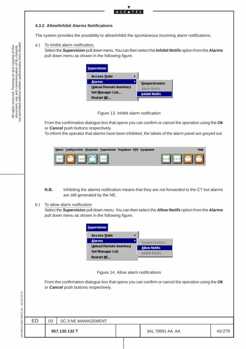
All
right
s re
serv
ed. P
assi
ng o
n an
d co
pyin
g of
this
docu
men
t, us
e an
d co
mm
unic
atio
n of
its
cont
ents
not p
erm
itted
with
out w
ritte
n au
thor
izat
ion
from
Alc
atel
.
ED
1AA
000
14 0
004
(900
7) A
4 –
ALI
CE
04.
10
43
03
957.130.132 T
SC.3:NE MANAGEMENT
/3AL 78991 AA AA
278
278
4.3.2 Allow/Inhibit Alarms Notifications
The system provides the possibility to allow/inhibit the spontaneous incoming alarm notifications.
a ) To inhibit alarm notification,Select the Supervision pull down menu. You can then select the Inhibit Notifs option from the Alarmspull down menu as shown in the following figure.
Figure 13. Inhibit alarm notification
From the confirmation dialogue box that opens you can confirm or cancel the operation using the Okor Cancel push buttons respectively.To inform the operator that alarms have been inhibited, the labels of the alarm panel are greyed out.
N.B. Inhibiting the alarms notification means that they are not forwarded to the CT but alarmsare still generated by the NE.
b ) To allow alarm notificationSelect the Supervision pull down menu. You can then select the Allow Notifs option from the Alarmspull down menu as shown in the following figure.
Figure 14. Allow alarm notifications
From the confirmation dialogue box that opens you can confirm or cancel the operation using the Okor Cancel push buttons respectively.
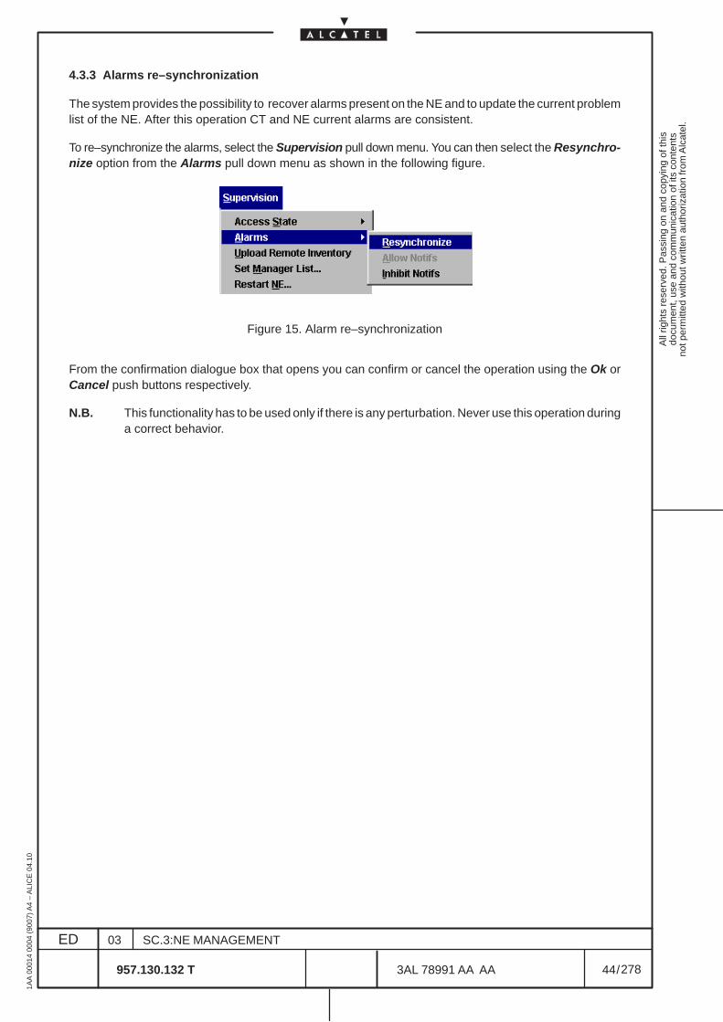
All
right
s re
serv
ed. P
assi
ng o
n an
d co
pyin
g of
this
docu
men
t, us
e an
d co
mm
unic
atio
n of
its
cont
ents
not p
erm
itted
with
out w
ritte
n au
thor
izat
ion
from
Alc
atel
.
ED
1AA
000
14 0
004
(900
7) A
4 –
ALI
CE
04.
10
44
03
957.130.132 T
SC.3:NE MANAGEMENT
/3AL 78991 AA AA
278
278
4.3.3 Alarms re–synchronization
The system provides the possibility to recover alarms present on the NE and to update the current problemlist of the NE. After this operation CT and NE current alarms are consistent.
To re–synchronize the alarms, select the Supervision pull down menu. You can then select the Resynchro-nize option from the Alarms pull down menu as shown in the following figure.
Figure 15. Alarm re–synchronization
From the confirmation dialogue box that opens you can confirm or cancel the operation using the Ok orCancel push buttons respectively.
N.B. This functionality has to be used only if there is any perturbation. Never use this operation duringa correct behavior.
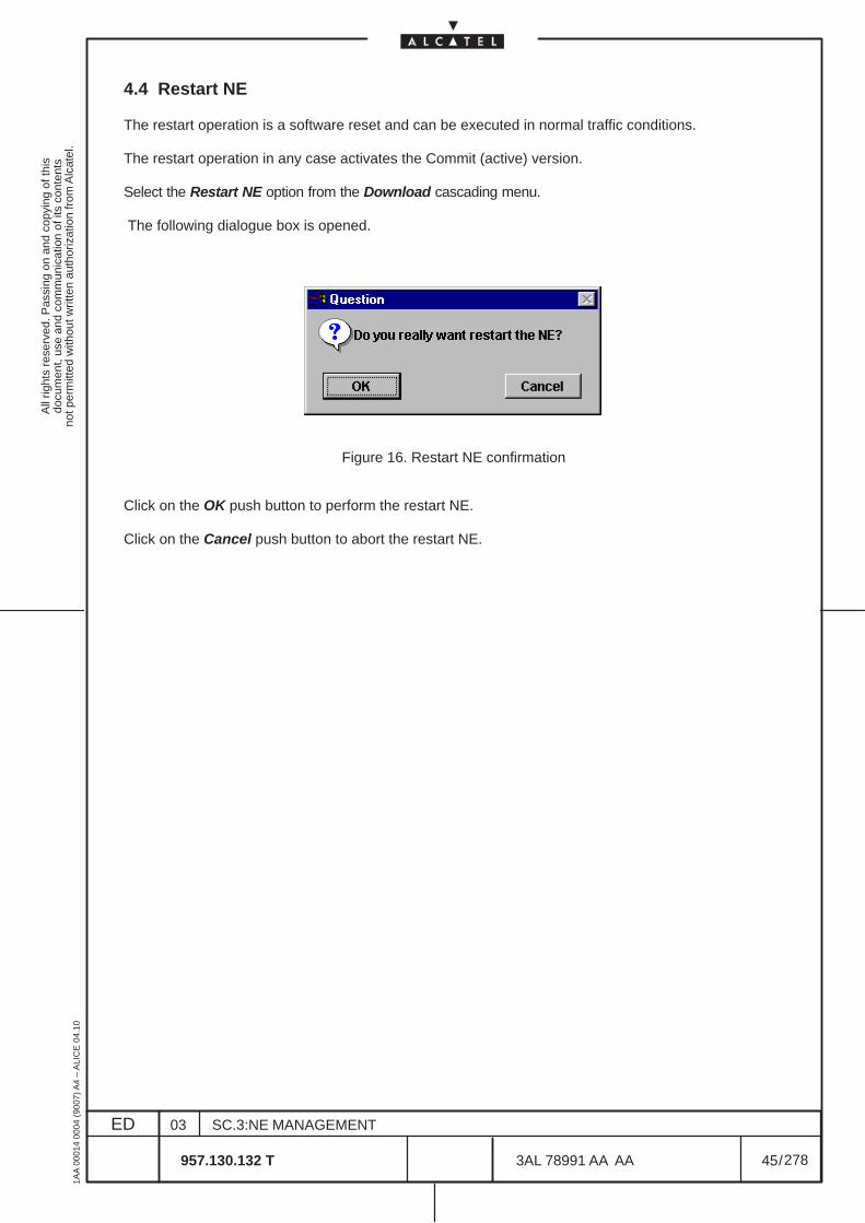
All
right
s re
serv
ed. P
assi
ng o
n an
d co
pyin
g of
this
docu
men
t, us
e an
d co
mm
unic
atio
n of
its
cont
ents
not p
erm
itted
with
out w
ritte
n au
thor
izat
ion
from
Alc
atel
.
ED
1AA
000
14 0
004
(900
7) A
4 –
ALI
CE
04.
10
45
03
957.130.132 T
SC.3:NE MANAGEMENT
/3AL 78991 AA AA
278
278
4.4 Restart NE
The restart operation is a software reset and can be executed in normal traffic conditions.
The restart operation in any case activates the Commit (active) version.
Select the Restart NE option from the Download cascading menu.
The following dialogue box is opened.
Figure 16. Restart NE confirmation
Click on the OK push button to perform the restart NE.
Click on the Cancel push button to abort the restart NE.

All
right
s re
serv
ed. P
assi
ng o
n an
d co
pyin
g of
this
docu
men
t, us
e an
d co
mm
unic
atio
n of
its
cont
ents
not p
erm
itted
with
out w
ritte
n au
thor
izat
ion
from
Alc
atel
.
ED
1AA
000
14 0
004
(900
7) A
4 –
ALI
CE
04.
10
46
03
957.130.132 T
SC.3:NE MANAGEMENT
/3AL 78991 AA AA
278
278
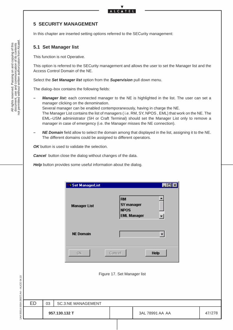
All
right
s re
serv
ed. P
assi
ng o
n an
d co
pyin
g of
this
docu
men
t, us
e an
d co
mm
unic
atio
n of
its
cont
ents
not p
erm
itted
with
out w
ritte
n au
thor
izat
ion
from
Alc
atel
.
ED
1AA
000
14 0
004
(900
7) A
4 –
ALI
CE
04.
10
47
03
957.130.132 T
SC.3:NE MANAGEMENT
/3AL 78991 AA AA
278
278
5 SECURITY MANAGEMENT
In this chapter are inserted setting options referred to the SECurity management:
5.1 Set Manager list
This function is not Operative.
This option is referred to the SECurity management and allows the user to set the Manager list and theAccess Control Domain of the NE.
Select the Set Manager list option from the Supervision pull down menu.
The dialog–box contains the following fields:
– Manager list: each connected manager to the NE is highlighted in the list. The user can set amanager clicking on the denomination.Several manager can be enabled contemporaneously, having in charge the NE.The Manager List contains the list of managers ( i.e. RM, SY, NPOS , EML) that work on the NE. TheEML–USM administrator (SH or Craft Terminal) should set the Manager List only to remove amanager in case of emergency (i.e. the Manager misses the NE connection).
– NE Domain field allow to select the domain among that displayed in the list, assigning it to the NE.The different domains could be assigned to different operators.
OK button is used to validate the selection.
Cancel button close the dialog without changes of the data.
Help button provides some useful information about the dialog.
Figure 17. Set Manager list
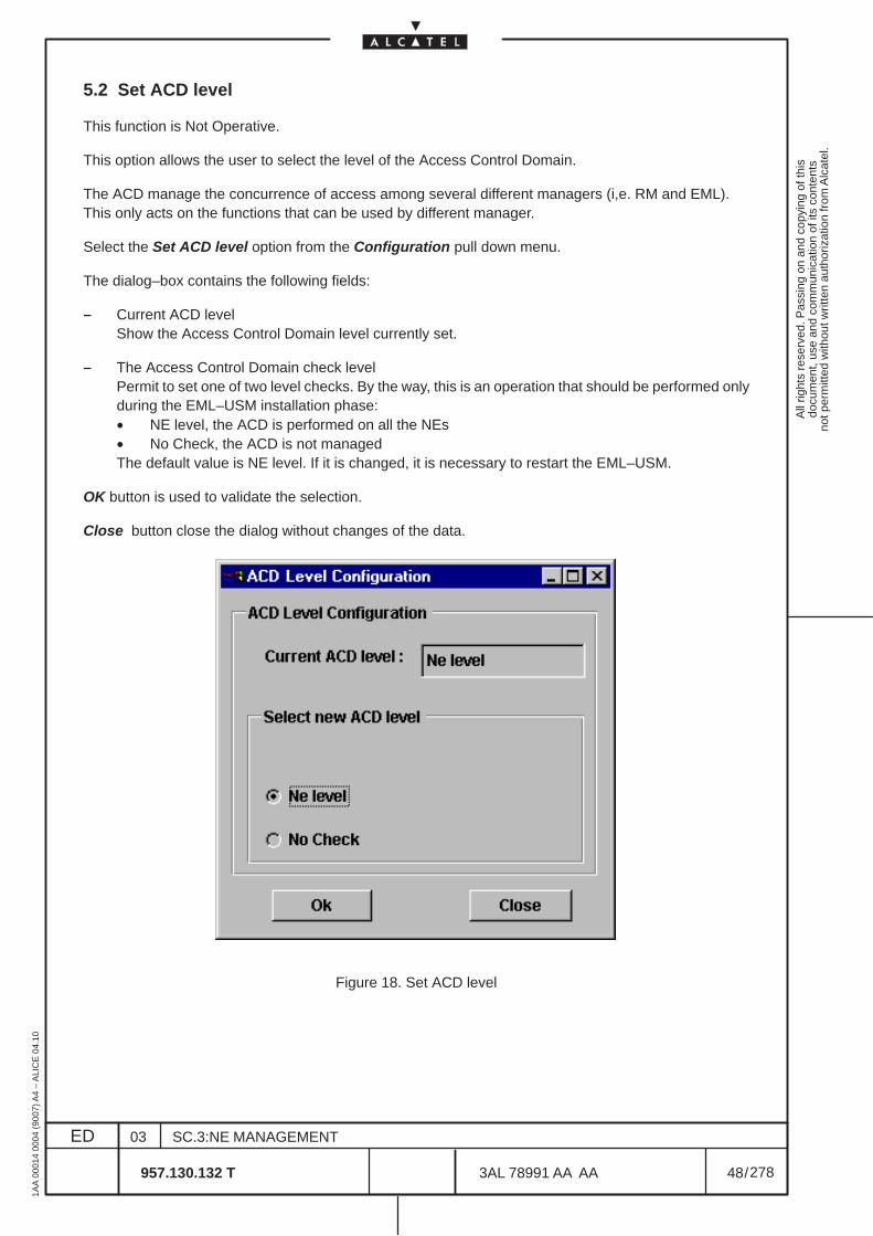
All
right
s re
serv
ed. P
assi
ng o
n an
d co
pyin
g of
this
docu
men
t, us
e an
d co
mm
unic
atio
n of
its
cont
ents
not p
erm
itted
with
out w
ritte
n au
thor
izat
ion
from
Alc
atel
.
ED
1AA
000
14 0
004
(900
7) A
4 –
ALI
CE
04.
10
48
03
957.130.132 T
SC.3:NE MANAGEMENT
/3AL 78991 AA AA
278
278
5.2 Set ACD level
This function is Not Operative.
This option allows the user to select the level of the Access Control Domain.
The ACD manage the concurrence of access among several different managers (i,e. RM and EML).This only acts on the functions that can be used by different manager.
Select the Set ACD level option from the Configuration pull down menu.
The dialog–box contains the following fields:
– Current ACD levelShow the Access Control Domain level currently set.
– The Access Control Domain check levelPermit to set one of two level checks. By the way, this is an operation that should be performed onlyduring the EML–USM installation phase:• NE level, the ACD is performed on all the NEs• No Check, the ACD is not managedThe default value is NE level. If it is changed, it is necessary to restart the EML–USM.
OK button is used to validate the selection.
Close button close the dialog without changes of the data.
Figure 18. Set ACD level
All
right
s re
serv
ed. P
assi
ng o
n an
d co
pyin
g of
this
docu
men
t, us
e an
d co
mm
unic
atio
n of
its
cont
ents
not p
erm
itted
with
out w
ritte
n au
thor
izat
ion
from
Alc
atel
.
ED
1AA
000
14 0
004
(900
7) A
4 –
ALI
CE
04.
10
49
03
957.130.132 T
SC.3:NE MANAGEMENT
/3AL 78991 AA AA
278
278
6 EXTERNAL INPUT AND OUTPUT POINTS MANAGEMENT
This chapter describes how to display and set the input/output environmental alarm (housekeeping alarm),
An external input point is an environmental alarm (also called housekeeping alarm). It corresponds to anexternal event which is monitored by the NE. Number of relays on the NE are dedicated to checkmodification of the environment as for example a fire, a flood ...
An external output point is used to manage a NE contact (i.e relay) connected to detector. An externaloutput point is independent from external input point.
The operations that can be undertaken in this section are:
– Displaying external points,
– Expanding or reducing external points list,
– Configuring input and output external points.
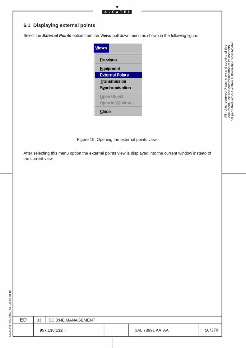
All
right
s re
serv
ed. P
assi
ng o
n an
d co
pyin
g of
this
docu
men
t, us
e an
d co
mm
unic
atio
n of
its
cont
ents
not p
erm
itted
with
out w
ritte
n au
thor
izat
ion
from
Alc
atel
.
ED
1AA
000
14 0
004
(900
7) A
4 –
ALI
CE
04.
10
50
03
957.130.132 T
SC.3:NE MANAGEMENT
/3AL 78991 AA AA
278
278
6.1 Displaying external points
Select the External Points option from the Views pull down menu as shown in the following figure.
Figure 19. Opening the external points view.
After selecting this menu option the external points view is displayed into the current window instead ofthe current view.
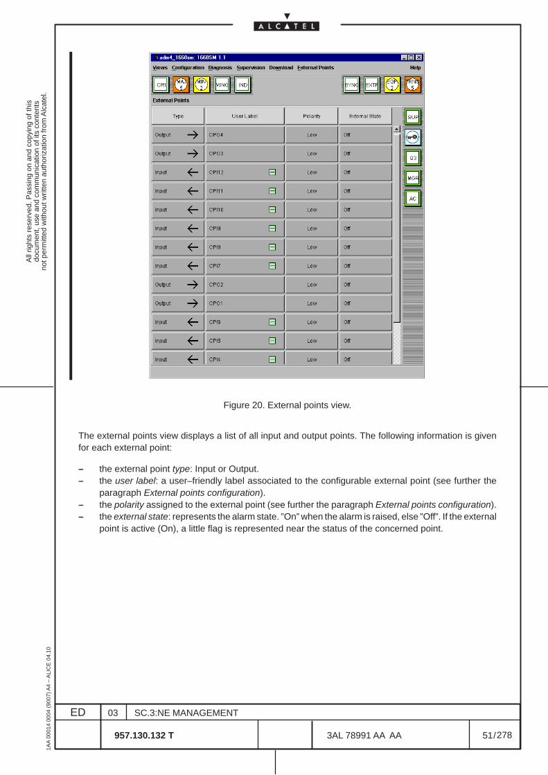
All
right
s re
serv
ed. P
assi
ng o
n an
d co
pyin
g of
this
docu
men
t, us
e an
d co
mm
unic
atio
n of
its
cont
ents
not p
erm
itted
with
out w
ritte
n au
thor
izat
ion
from
Alc
atel
.
ED
1AA
000
14 0
004
(900
7) A
4 –
ALI
CE
04.
10
51
03
957.130.132 T
SC.3:NE MANAGEMENT
/3AL 78991 AA AA
278
278
Figure 20. External points view.
The external points view displays a list of all input and output points. The following information is givenfor each external point:
– the external point type: Input or Output.– the user label: a user–friendly label associated to the configurable external point (see further the
paragraph External points configuration).– the polarity assigned to the external point (see further the paragraph External points configuration).– the external state: represents the alarm state. ”On” when the alarm is raised, else ”Off”. If the external
point is active (On), a little flag is represented near the status of the concerned point.
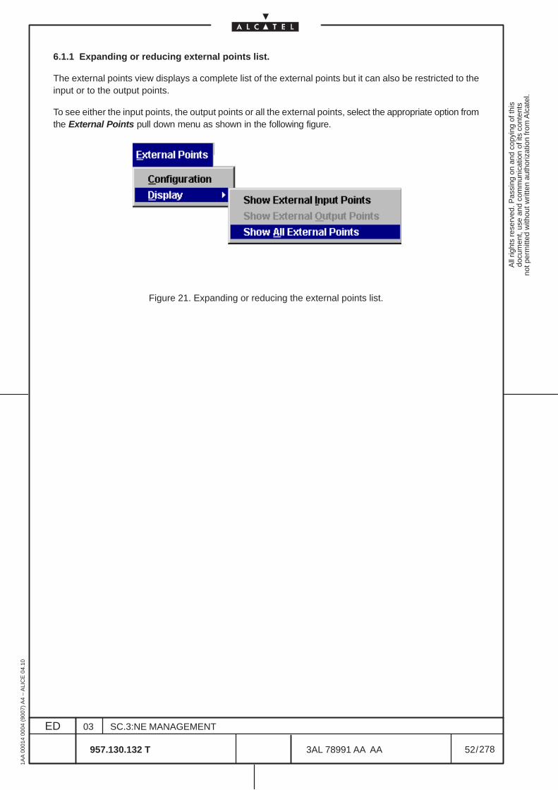
All
right
s re
serv
ed. P
assi
ng o
n an
d co
pyin
g of
this
docu
men
t, us
e an
d co
mm
unic
atio
n of
its
cont
ents
not p
erm
itted
with
out w
ritte
n au
thor
izat
ion
from
Alc
atel
.
ED
1AA
000
14 0
004
(900
7) A
4 –
ALI
CE
04.
10
52
03
957.130.132 T
SC.3:NE MANAGEMENT
/3AL 78991 AA AA
278
278
6.1.1 Expanding or reducing external points list.
The external points view displays a complete list of the external points but it can also be restricted to theinput or to the output points.
To see either the input points, the output points or all the external points, select the appropriate option fromthe External Points pull down menu as shown in the following figure.
Figure 21. Expanding or reducing the external points list.
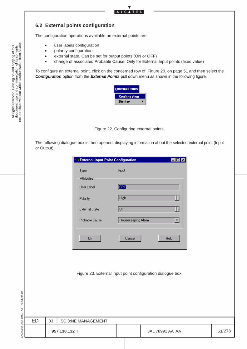
All
right
s re
serv
ed. P
assi
ng o
n an
d co
pyin
g of
this
docu
men
t, us
e an
d co
mm
unic
atio
n of
its
cont
ents
not p
erm
itted
with
out w
ritte
n au
thor
izat
ion
from
Alc
atel
.
ED
1AA
000
14 0
004
(900
7) A
4 –
ALI
CE
04.
10
53
03
957.130.132 T
SC.3:NE MANAGEMENT
/3AL 78991 AA AA
278
278
6.2 External points configuration
The configuration operations available on external points are:
• user labels configuration• polarity configuration• external state. Can be set for output points (ON or OFF)• change of associated Probable Cause. Only for External Input points (fixed value)
To configure an external point, click on the concerned row of Figure 20. on page 51 and then select theConfiguration option from the External Points pull down menu as shown in the following figure.
Figure 22. Configuring external points.
The following dialogue box is then opened, displaying information about the selected external point (Inputor Output).
Figure 23. External input point configuration dialogue box.
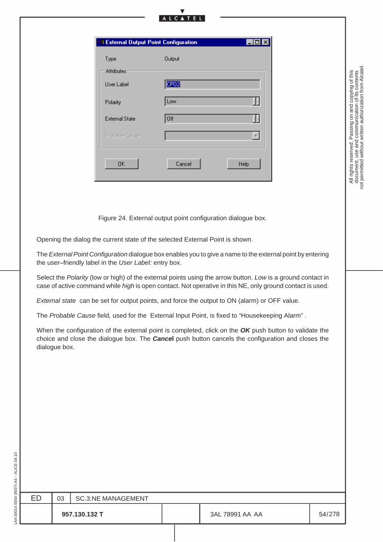
All
right
s re
serv
ed. P
assi
ng o
n an
d co
pyin
g of
this
docu
men
t, us
e an
d co
mm
unic
atio
n of
its
cont
ents
not p
erm
itted
with
out w
ritte
n au
thor
izat
ion
from
Alc
atel
.
ED
1AA
000
14 0
004
(900
7) A
4 –
ALI
CE
04.
10
54
03
957.130.132 T
SC.3:NE MANAGEMENT
/3AL 78991 AA AA
278
278
Figure 24. External output point configuration dialogue box.
Opening the dialog the current state of the selected External Point is shown.
The External Point Configuration dialogue box enables you to give a name to the external point by enteringthe user–friendly label in the User Label: entry box.
Select the Polarity (low or high) of the external points using the arrow button. Low is a ground contact incase of active command while high is open contact. Not operative in this NE, only ground contact is used.
External state can be set for output points, and force the output to ON (alarm) or OFF value.
The Probable Cause field, used for the External Input Point, is fixed to “Housekeeping Alarm” .
When the configuration of the external point is completed, click on the OK push button to validate thechoice and close the dialogue box. The Cancel push button cancels the configuration and closes thedialogue box.
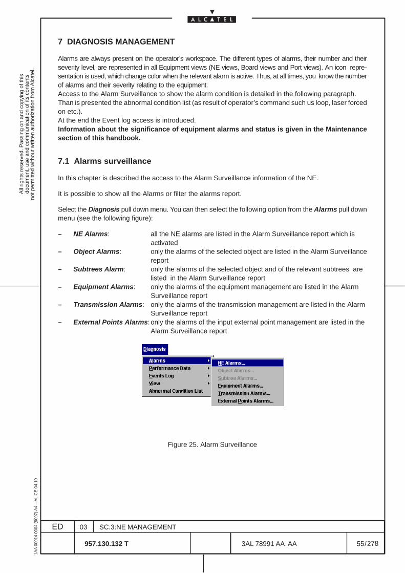
All
right
s re
serv
ed. P
assi
ng o
n an
d co
pyin
g of
this
docu
men
t, us
e an
d co
mm
unic
atio
n of
its
cont
ents
not p
erm
itted
with
out w
ritte
n au
thor
izat
ion
from
Alc
atel
.
ED
1AA
000
14 0
004
(900
7) A
4 –
ALI
CE
04.
10
55
03
957.130.132 T
SC.3:NE MANAGEMENT
/3AL 78991 AA AA
278
278
7 DIAGNOSIS MANAGEMENT
Alarms are always present on the operator’s workspace. The different types of alarms, their number and theirseverity level, are represented in all Equipment views (NE views, Board views and Port views). An icon repre-sentation is used, which change color when the relevant alarm is active. Thus, at all times, you know the numberof alarms and their severity relating to the equipment.Access to the Alarm Surveillance to show the alarm condition is detailed in the following paragraph.Than is presented the abnormal condition list (as result of operator’s command such us loop, laser forcedon etc.).At the end the Event log access is introduced.Information about the significance of equipment alarms and status is given in the Maintenancesection of this handbook.
7.1 Alarms surveillance
In this chapter is described the access to the Alarm Surveillance information of the NE.
It is possible to show all the Alarms or filter the alarms report.
Select the Diagnosis pull down menu. You can then select the following option from the Alarms pull downmenu (see the following figure):
– NE Alarms: all the NE alarms are listed in the Alarm Surveillance report which isactivated
– Object Alarms: only the alarms of the selected object are listed in the Alarm Surveillancereport
– Subtrees Alarm: only the alarms of the selected object and of the relevant subtrees arelisted in the Alarm Surveillance report
– Equipment Alarms: only the alarms of the equipment management are listed in the AlarmSurveillance report
– Transmission Alarms: only the alarms of the transmission management are listed in the AlarmSurveillance report
– External Points Alarms: only the alarms of the input external point management are listed in theAlarm Surveillance report
Figure 25. Alarm Surveillance
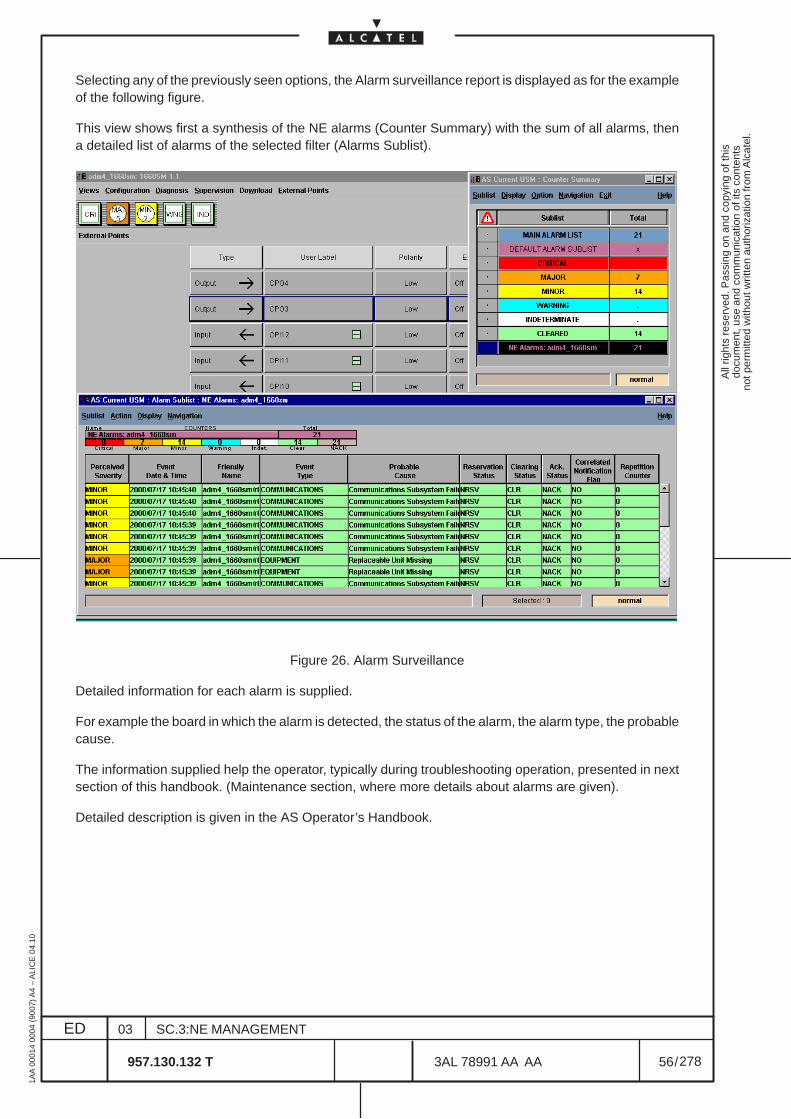
All
right
s re
serv
ed. P
assi
ng o
n an
d co
pyin
g of
this
docu
men
t, us
e an
d co
mm
unic
atio
n of
its
cont
ents
not p
erm
itted
with
out w
ritte
n au
thor
izat
ion
from
Alc
atel
.
ED
1AA
000
14 0
004
(900
7) A
4 –
ALI
CE
04.
10
56
03
957.130.132 T
SC.3:NE MANAGEMENT
/3AL 78991 AA AA
278
278
Selecting any of the previously seen options, the Alarm surveillance report is displayed as for the exampleof the following figure.
This view shows first a synthesis of the NE alarms (Counter Summary) with the sum of all alarms, thena detailed list of alarms of the selected filter (Alarms Sublist).
Figure 26. Alarm Surveillance
Detailed information for each alarm is supplied.
For example the board in which the alarm is detected, the status of the alarm, the alarm type, the probablecause.
The information supplied help the operator, typically during troubleshooting operation, presented in nextsection of this handbook. (Maintenance section, where more details about alarms are given).
Detailed description is given in the AS Operator’s Handbook.
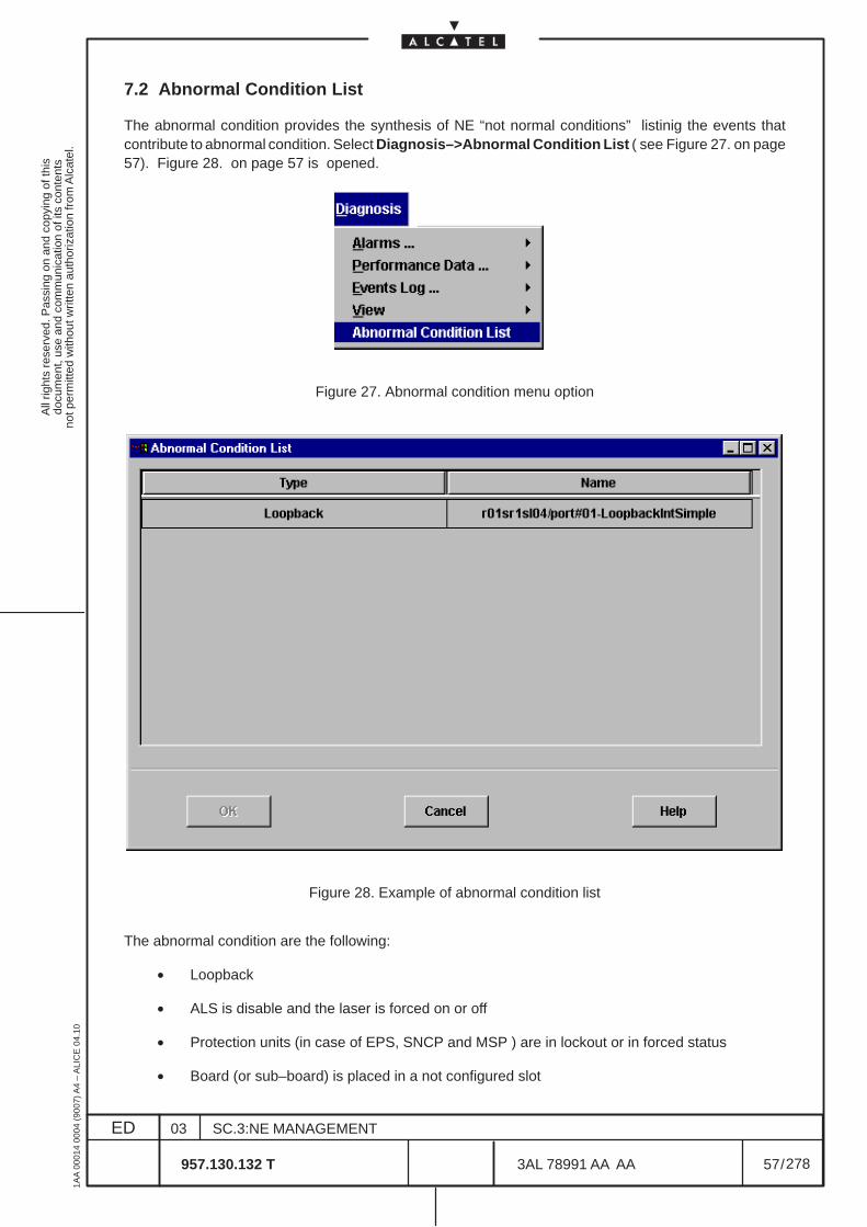
All
right
s re
serv
ed. P
assi
ng o
n an
d co
pyin
g of
this
docu
men
t, us
e an
d co
mm
unic
atio
n of
its
cont
ents
not p
erm
itted
with
out w
ritte
n au
thor
izat
ion
from
Alc
atel
.
ED
1AA
000
14 0
004
(900
7) A
4 –
ALI
CE
04.
10
57
03
957.130.132 T
SC.3:NE MANAGEMENT
/3AL 78991 AA AA
278
278
7.2 Abnormal Condition List
The abnormal condition provides the synthesis of NE “not normal conditions” listinig the events thatcontribute to abnormal condition. Select Diagnosis–>Abnormal Condition List ( see Figure 27. on page57). Figure 28. on page 57 is opened.
Figure 27. Abnormal condition menu option
r01sr1sl02/port#01–P
Figure 28. Example of abnormal condition list
The abnormal condition are the following:
• Loopback
• ALS is disable and the laser is forced on or off
• Protection units (in case of EPS, SNCP and MSP ) are in lockout or in forced status
• Board (or sub–board) is placed in a not configured slot
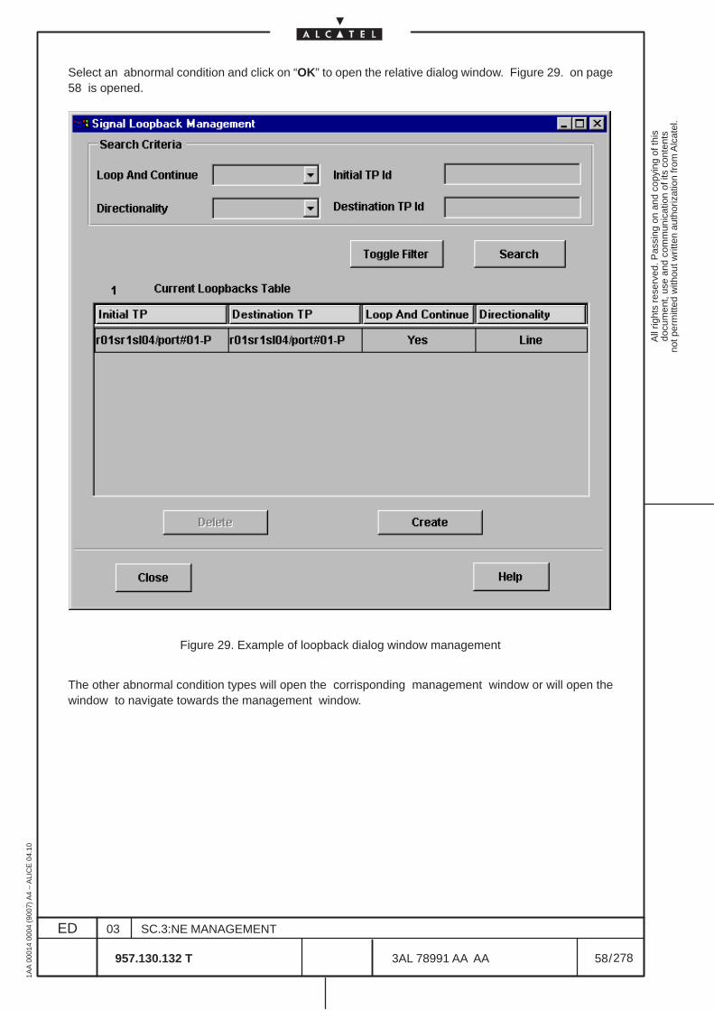
All
right
s re
serv
ed. P
assi
ng o
n an
d co
pyin
g of
this
docu
men
t, us
e an
d co
mm
unic
atio
n of
its
cont
ents
not p
erm
itted
with
out w
ritte
n au
thor
izat
ion
from
Alc
atel
.
ED
1AA
000
14 0
004
(900
7) A
4 –
ALI
CE
04.
10
58
03
957.130.132 T
SC.3:NE MANAGEMENT
/3AL 78991 AA AA
278
278
Select an abnormal condition and click on “OK” to open the relative dialog window. Figure 29. on page58 is opened.
Figure 29. Example of loopback dialog window management
The other abnormal condition types will open the corrisponding management window or will open thewindow to navigate towards the management window.
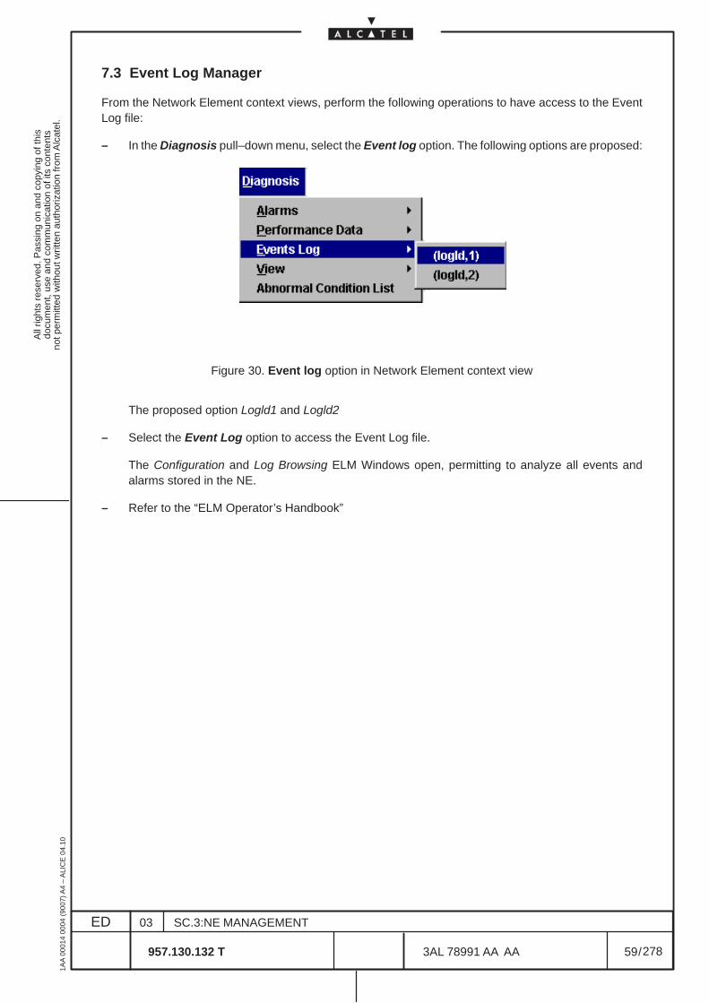
All
right
s re
serv
ed. P
assi
ng o
n an
d co
pyin
g of
this
docu
men
t, us
e an
d co
mm
unic
atio
n of
its
cont
ents
not p
erm
itted
with
out w
ritte
n au
thor
izat
ion
from
Alc
atel
.
ED
1AA
000
14 0
004
(900
7) A
4 –
ALI
CE
04.
10
59
03
957.130.132 T
SC.3:NE MANAGEMENT
/3AL 78991 AA AA
278
278
7.3 Event Log Manager
From the Network Element context views, perform the following operations to have access to the EventLog file:
– In the Diagnosis pull–down menu, select the Event log option. The following options are proposed:
Figure 30. Event log option in Network Element context view
The proposed option Logld1 and Logld2
– Select the Event Log option to access the Event Log file.
The Configuration and Log Browsing ELM Windows open, permitting to analyze all events andalarms stored in the NE.
– Refer to the “ELM Operator’s Handbook”
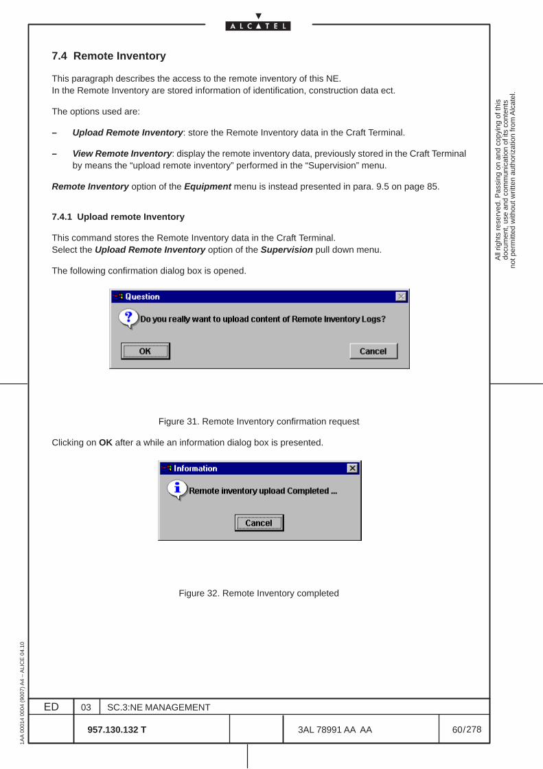
All
right
s re
serv
ed. P
assi
ng o
n an
d co
pyin
g of
this
docu
men
t, us
e an
d co
mm
unic
atio
n of
its
cont
ents
not p
erm
itted
with
out w
ritte
n au
thor
izat
ion
from
Alc
atel
.
ED
1AA
000
14 0
004
(900
7) A
4 –
ALI
CE
04.
10
60
03
957.130.132 T
SC.3:NE MANAGEMENT
/3AL 78991 AA AA
278
278
7.4 Remote Inventory
This paragraph describes the access to the remote inventory of this NE.In the Remote Inventory are stored information of identification, construction data ect.
The options used are:
– Upload Remote Inventory: store the Remote Inventory data in the Craft Terminal.
– View Remote Inventory: display the remote inventory data, previously stored in the Craft Terminalby means the “upload remote inventory” performed in the “Supervision” menu.
Remote Inventory option of the Equipment menu is instead presented in para. 9.5 on page 85.
7.4.1 Upload remote Inventory
This command stores the Remote Inventory data in the Craft Terminal.Select the Upload Remote Inventory option of the Supervision pull down menu.
The following confirmation dialog box is opened.
Figure 31. Remote Inventory confirmation request
Clicking on OK after a while an information dialog box is presented.
Figure 32. Remote Inventory completed
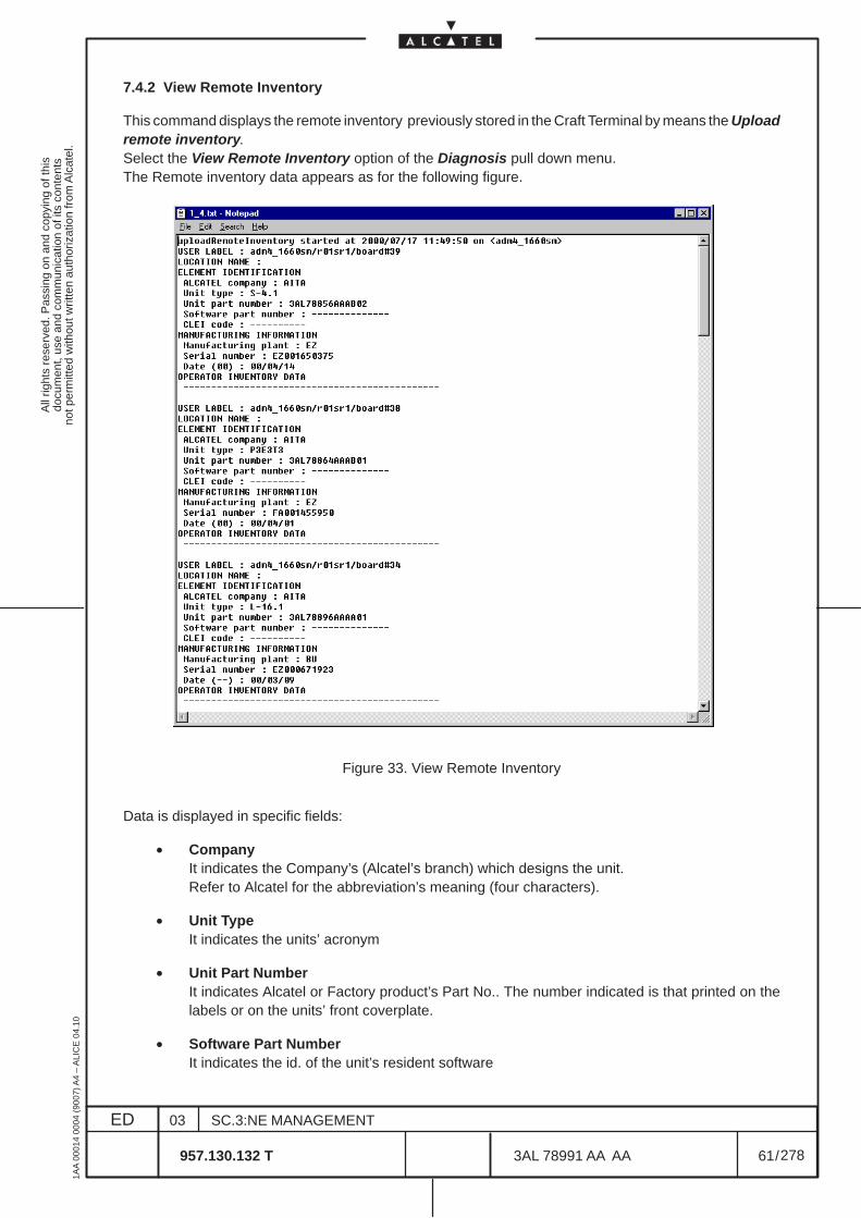
All
right
s re
serv
ed. P
assi
ng o
n an
d co
pyin
g of
this
docu
men
t, us
e an
d co
mm
unic
atio
n of
its
cont
ents
not p
erm
itted
with
out w
ritte
n au
thor
izat
ion
from
Alc
atel
.
ED
1AA
000
14 0
004
(900
7) A
4 –
ALI
CE
04.
10
61
03
957.130.132 T
SC.3:NE MANAGEMENT
/3AL 78991 AA AA
278
278
7.4.2 View Remote Inventory
This command displays the remote inventory previously stored in the Craft Terminal by means the Uploadremote inventory.Select the View Remote Inventory option of the Diagnosis pull down menu.The Remote inventory data appears as for the following figure.
Figure 33. View Remote Inventory
Data is displayed in specific fields:
• CompanyIt indicates the Company’s (Alcatel’s branch) which designs the unit.Refer to Alcatel for the abbreviation’s meaning (four characters).
• Unit TypeIt indicates the units’ acronym
• Unit Part NumberIt indicates Alcatel or Factory product’s Part No.. The number indicated is that printed on thelabels or on the units’ front coverplate.
• Software Part NumberIt indicates the id. of the unit’s resident software
All
right
s re
serv
ed. P
assi
ng o
n an
d co
pyin
g of
this
docu
men
t, us
e an
d co
mm
unic
atio
n of
its
cont
ents
not p
erm
itted
with
out w
ritte
n au
thor
izat
ion
from
Alc
atel
.
ED
1AA
000
14 0
004
(900
7) A
4 –
ALI
CE
04.
10
62
03
957.130.132 T
SC.3:NE MANAGEMENT
/3AL 78991 AA AA
278
278
• CLEI CodeIt indicates the CLEI code according to Bellecore specs. TR–ISD–325
• Manufacturing plantIt indicates the Company’s manufacturing plant id. within the company, producing the unit.Refer to Alcatel for the abbreviation’s meaning (four characters).
• Serial NumberIt indicates the product’s serial number as specified by the NR 130 Norm.
• Date identifierIt indicates the meaning of the date that follow.It is a two–digit code supplying the following information:
00 date of construction at the time of final testing01 production order data02 construction date of the unit lot03 date product has been forwarded to customer04 customer order date
• Date (YYMMDD)The identification of the date depends on the indications stated in the previous field. When onlythe year is displayed, the format must be ”YY– – – – ”
All
right
s re
serv
ed. P
assi
ng o
n an
d co
pyin
g of
this
docu
men
t, us
e an
d co
mm
unic
atio
n of
its
cont
ents
not p
erm
itted
with
out w
ritte
n au
thor
izat
ion
from
Alc
atel
.
ED
1AA
000
14 0
004
(900
7) A
4 –
ALI
CE
04.
10
63
03
957.130.132 T
SC.3:NE MANAGEMENT
/3AL 78991 AA AA
278
278
8 COMMUNICATION AND ROUTING MANAGEMENT
8.1 Overview on Communication and Routing Domain
The purpose of the communication and routing domain is to define configuration parameters concerningthe communication protocols for the local NE, the OS and each other related NE in order to provide aglobal communication capabilities inside the network.
A brief description of basic concepts and terms involved in the communication and routing domain follows.
During the TMN design process, a network is partitioned into domains; each domain can consist of acollection of two types of nodes:
• nodes supporting a link state routing protocol IS–IS; these nodes will be called adaptiverouters; IS–IS protocol floods the network with link state information in order to build a completeconsistent picture of the network topology. Use of IS–IS routing protocol in a TMN facilitatesinstallation and operation due to the ”self learning” capabilities of these protocols and automaticnetwork reconfiguration in case of failure; moreover the use of these standardized routingprotocols guarantees interoperability in a multivendor environment.
• nodes not supporting these protocols; these nodes will be called static routers;
Networks partitions consisting of the former type of node will be called adaptive routing domains;networks partitions consisting of the later type of node will be called static routing domains.
Moreover, a node which have to take routing decisions must became Intermediate Systems, all otherscan be made End Systems
For the description of the following paragraphs use is made of Figure 34. on page 65. It is not a networkplanning example, it is only used to describe L1 ,L2, RAP and MESA.
8.1.1 Partitioning into Routing Subdomains
In order to reduce the overhead associated with distributed adaptive routing, it may be useful to dividea adaptive routing domain into smaller routing subdomains, called areas or level 1 subdomain. A level1 subdomain should fulfill the following requirements:
• a level 1 subdomain should form a connected subnetwork; this subnetwork should have onlya few links to the outside world, compared with the number of internal links;
• each node must belong to exactly one level 1 subdomain;• each node which is connected to a foreign level 1 subdomain must become a level 2
intermediate system; level 1 intermediate systems know how to communicate only with ISin the same area; obviously, there must be at least one level 2 intermediate system per level1 subdomain;
• Level 2 intermediate systems must form a connected network, because level 1 paths cannotbe utilized for level 2 communication. This network will be called level 2 backbone.
In the most simple case, all nodes within a level 1 subdomain share the same area address.In general it is allowed to have multiple synonymous area addresses within a level 1 subdomain even ifthe usage of this features should be checked with Alcatel engineers.The synonymous list is used to ease partitioning in the future. There is a basic rule, which must be followedby two neighboring level 1 intermediate systems within a subdomain: there must be at least one areaaddress in common between their two synonymous list, otherwise they are not able to communicate witheach other.
All
right
s re
serv
ed. P
assi
ng o
n an
d co
pyin
g of
this
docu
men
t, us
e an
d co
mm
unic
atio
n of
its
cont
ents
not p
erm
itted
with
out w
ritte
n au
thor
izat
ion
from
Alc
atel
.
ED
1AA
000
14 0
004
(900
7) A
4 –
ALI
CE
04.
10
64
03
957.130.132 T
SC.3:NE MANAGEMENT
/3AL 78991 AA AA
278
278
8.1.2 Partitioning into separate Routing Domains
In certain situations it may be necessary to partition a given network into separate routing domains, whereno routing information is exchanged between these domains. The major benefits of this partitioning arereduction of memory, processing and traffic overhead, because there is no exchange of routinginformation between the domains. Communication between separate routing domains must be achievedthrough the use of Reachable Address Prefixes (RAP).A Reachable Address Prefixes represents static routing information. It can only be associated with a linkof a level 2 intermediate system, whereby this link crosses routing domain boundaries. A ReachableAddress Prefixes is handled in the same way as information about a foreign level 1 subdomain within theown domain. The Reachable Address Prefixes indicates that any packet whose destination networkaddress NSAP matches the prefix may be forwarded via the link with witch the prefix is associated.
For example, consider network which is split into two separate routing domains:• routing domain A resides in a level 1 subdomain with area address ”a”• routing domain B resides in a level 1 subdomain with area address ”b”
In order to enable the communication, the Reachable Address Prefixes in routing domain A must containthe area address ”b” and the Reachable Address Prefixes in routing domain B must contain the areaaddress ”a”.On the other hand, within a given level 1 subdomain, there can be some NEs not supporting IS–IS norES–IS protocol (static routing). In such condition, the communication can be achieved through the useof Manual End System Adjacencies (MESA).A prerequisite for the use of manual end system adjacencies is that the area addresses of the connectednodes must be the same; as a consequence the nodes must belong to the same level 1 subdomain.Within a pure Alcatel network there is no need to use any kind of static routing. Therefore normally RAPand MESA shall never be used.
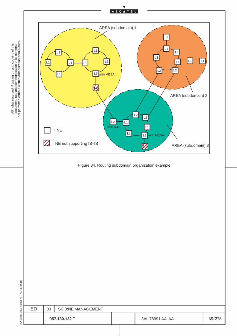
All
right
s re
serv
ed. P
assi
ng o
n an
d co
pyin
g of
this
docu
men
t, us
e an
d co
mm
unic
atio
n of
its
cont
ents
not p
erm
itted
with
out w
ritte
n au
thor
izat
ion
from
Alc
atel
.
ED
1AA
000
14 0
004
(900
7) A
4 –
ALI
CE
04.
10
65
03
957.130.132 T
SC.3:NE MANAGEMENT
/3AL 78991 AA AA
278
278
ÉÉÉÉ
AREA (subdomain) 1
AREA (subdomain) 3
AREA (subdomain) 2
= NE
L1
ÉÉÉÉ
= NE not supporting IS–IS
L1
L1
L1
L1
L1
L1
L1L2
L1
L1
L1
L1
L2L2
L2
ÉÉÉÉ
with MESA
with RAP
with MESA
L1
L1
L1
L1
L1
L1 L1 L1
L2 L2
Figure 34. Routing subdomain organization example
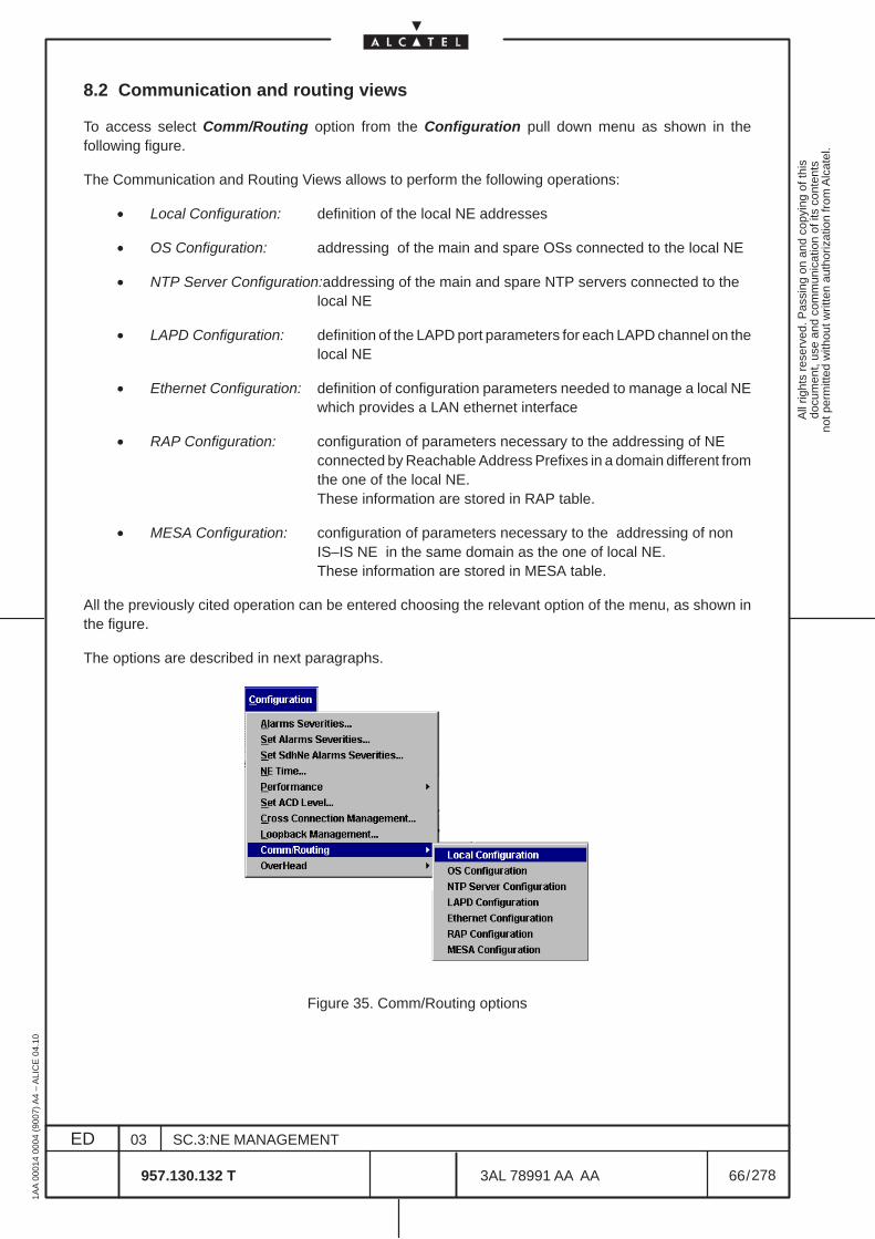
All
right
s re
serv
ed. P
assi
ng o
n an
d co
pyin
g of
this
docu
men
t, us
e an
d co
mm
unic
atio
n of
its
cont
ents
not p
erm
itted
with
out w
ritte
n au
thor
izat
ion
from
Alc
atel
.
ED
1AA
000
14 0
004
(900
7) A
4 –
ALI
CE
04.
10
66
03
957.130.132 T
SC.3:NE MANAGEMENT
/3AL 78991 AA AA
278
278
8.2 Communication and routing views
To access select Comm/Routing option from the Configuration pull down menu as shown in thefollowing figure.
The Communication and Routing Views allows to perform the following operations:
• Local Configuration: definition of the local NE addresses
• OS Configuration: addressing of the main and spare OSs connected to the local NE
• NTP Server Configuration:addressing of the main and spare NTP servers connected to thelocal NE
• LAPD Configuration: definition of the LAPD port parameters for each LAPD channel on thelocal NE
• Ethernet Configuration: definition of configuration parameters needed to manage a local NEwhich provides a LAN ethernet interface
• RAP Configuration: configuration of parameters necessary to the addressing of NEconnected by Reachable Address Prefixes in a domain different fromthe one of the local NE.These information are stored in RAP table.
• MESA Configuration: configuration of parameters necessary to the addressing of nonIS–IS NE in the same domain as the one of local NE.These information are stored in MESA table.
All the previously cited operation can be entered choosing the relevant option of the menu, as shown inthe figure.
The options are described in next paragraphs.
Figure 35. Comm/Routing options

All
right
s re
serv
ed. P
assi
ng o
n an
d co
pyin
g of
this
docu
men
t, us
e an
d co
mm
unic
atio
n of
its
cont
ents
not p
erm
itted
with
out w
ritte
n au
thor
izat
ion
from
Alc
atel
.
ED
1AA
000
14 0
004
(900
7) A
4 –
ALI
CE
04.
10
67
03
957.130.132 T
SC.3:NE MANAGEMENT
/3AL 78991 AA AA
278
278
8.3 Local Configuration
Select the Configuration pull down menu. Select the Comm/Routing option and then from the cascadingmenu the Local Configuration option.
The dialog–box opens (Figure 36. ) and allows to configure the local address of the NE.
The following fields are present:
– a Local Address section contains the following graphical object:
• a Presentation Selector (P.Sel) identifies a presentation entity at the location identified by theNSAP Address. The presented value must not be modified.
• a Section Selector (S. Selector) identifies a section entity at the location identified by the NSAPAddress. The presented value must not be modified.
• a Transport Selector (T. Sel) identifies a transport entity at the location identified by the NSAPAddress. The presented value must not be modified.
• a Network Service Access Point (NSAP) Address identifies a location in the network. The firstfield of the NSAP address, AFI, determines the NSAP format.The AFI filed is 2 characters long (2 exadecimal digits) and, depending on the its value, thelength of NSAP address is variable from 16 characters to 40 characters:– the value of AFI 49 identifies the local format of variable length (from 16 characters to 40
characters).– the value of AFI 39 identifies the ISO–DCC format of 40 characters long.– the value of AFI 47 identifies the GOSIP–V2 format of 40 characters long.
In all cases the last two fields of the NSAP address are:– System Id: uniquely identifies a NE in an area and is 12 characters long
It might be the equipment MAC Ethernet address, level 2, inserted in the NE (check thevalue in the para. 8.7 on page 72 ) or it might be selected by the operator.
– Network Selector: provides the distinction among users of the network service and is 2characters long (value is “1d”).
In the view, the NSAP is managed as simple strings of characters without any pre–formattingbecause of the variable format:– a first string of two characters that identifies the AFI field– a second string of variable length that identifies the remaining NSAP address
– Synonymous Area Addresses section allows to have multiple synonymous area addresses within alevel 1 subdomain. The compilation of the two network addresses is optional and if they are inserted,the last two fields, System Id and Network Selector, of the mandatory address and of the synonymousaddresses must be the same.
– System Type section determines whether the local NE acts as a “intermediate system level 1” or asa “intermediate system level 2” or as a “End System”. Note that a level 2 intermediate system per-forms functions of a level 1 too. End System is not operative.
Ok button is used to perform a configuration change of the data contained in the dialog–box and closesit; the dialog is visible until the end of the operations and a wait cursor is displayed.
Cancel button close the dialog without changes of the data.
Help button provides some useful information about the dialog.
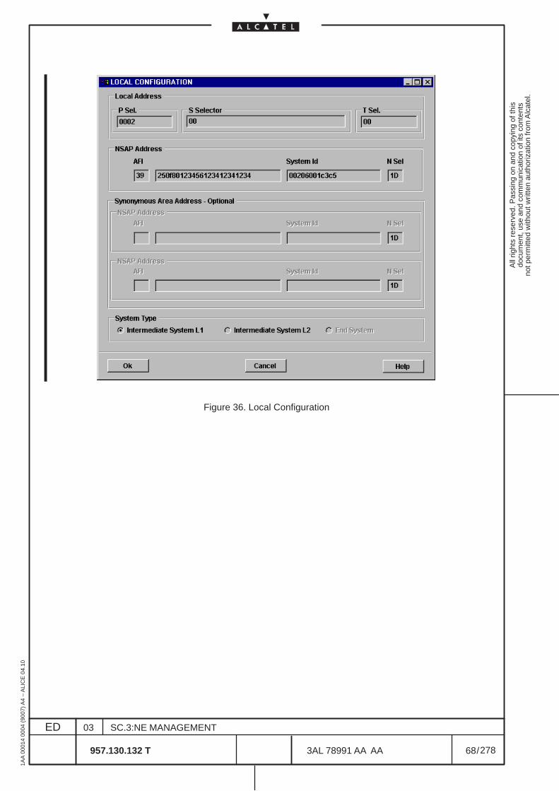
All
right
s re
serv
ed. P
assi
ng o
n an
d co
pyin
g of
this
docu
men
t, us
e an
d co
mm
unic
atio
n of
its
cont
ents
not p
erm
itted
with
out w
ritte
n au
thor
izat
ion
from
Alc
atel
.
ED
1AA
000
14 0
004
(900
7) A
4 –
ALI
CE
04.
10
68
03
957.130.132 T
SC.3:NE MANAGEMENT
/3AL 78991 AA AA
278
278
Figure 36. Local Configuration
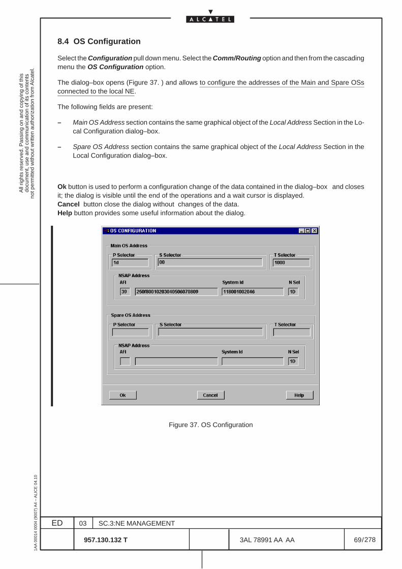
All
right
s re
serv
ed. P
assi
ng o
n an
d co
pyin
g of
this
docu
men
t, us
e an
d co
mm
unic
atio
n of
its
cont
ents
not p
erm
itted
with
out w
ritte
n au
thor
izat
ion
from
Alc
atel
.
ED
1AA
000
14 0
004
(900
7) A
4 –
ALI
CE
04.
10
69
03
957.130.132 T
SC.3:NE MANAGEMENT
/3AL 78991 AA AA
278
278
8.4 OS Configuration
Select the Configuration pull down menu. Select the Comm/Routing option and then from the cascadingmenu the OS Configuration option.
The dialog–box opens (Figure 37. ) and allows to configure the addresses of the Main and Spare OSsconnected to the local NE.
The following fields are present:
– Main OS Address section contains the same graphical object of the Local Address Section in the Lo-cal Configuration dialog–box.
– Spare OS Address section contains the same graphical object of the Local Address Section in theLocal Configuration dialog–box.
Ok button is used to perform a configuration change of the data contained in the dialog–box and closesit; the dialog is visible until the end of the operations and a wait cursor is displayed.Cancel button close the dialog without changes of the data.Help button provides some useful information about the dialog.
Figure 37. OS Configuration
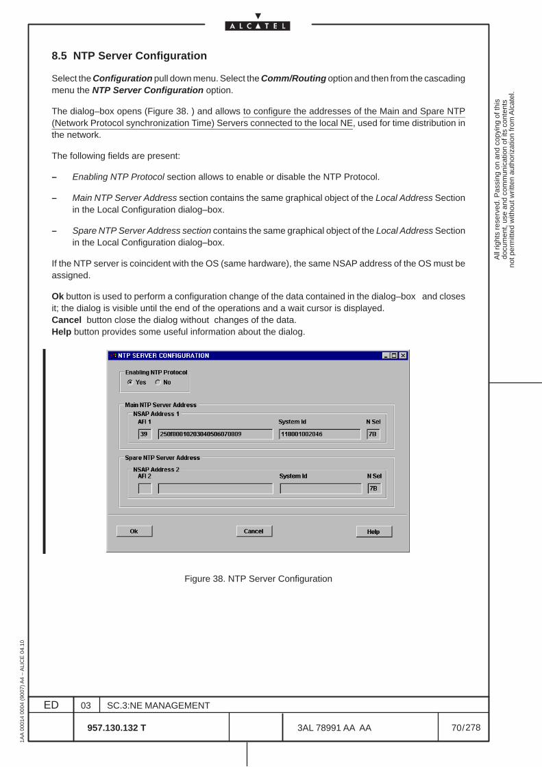
All
right
s re
serv
ed. P
assi
ng o
n an
d co
pyin
g of
this
docu
men
t, us
e an
d co
mm
unic
atio
n of
its
cont
ents
not p
erm
itted
with
out w
ritte
n au
thor
izat
ion
from
Alc
atel
.
ED
1AA
000
14 0
004
(900
7) A
4 –
ALI
CE
04.
10
70
03
957.130.132 T
SC.3:NE MANAGEMENT
/3AL 78991 AA AA
278
278
8.5 NTP Server Configuration
Select the Configuration pull down menu. Select the Comm/Routing option and then from the cascadingmenu the NTP Server Configuration option.
The dialog–box opens (Figure 38. ) and allows to configure the addresses of the Main and Spare NTP(Network Protocol synchronization Time) Servers connected to the local NE, used for time distribution inthe network.
The following fields are present:
– Enabling NTP Protocol section allows to enable or disable the NTP Protocol.
– Main NTP Server Address section contains the same graphical object of the Local Address Sectionin the Local Configuration dialog–box.
– Spare NTP Server Address section contains the same graphical object of the Local Address Sectionin the Local Configuration dialog–box.
If the NTP server is coincident with the OS (same hardware), the same NSAP address of the OS must beassigned.
Ok button is used to perform a configuration change of the data contained in the dialog–box and closesit; the dialog is visible until the end of the operations and a wait cursor is displayed.Cancel button close the dialog without changes of the data.Help button provides some useful information about the dialog.
Figure 38. NTP Server Configuration
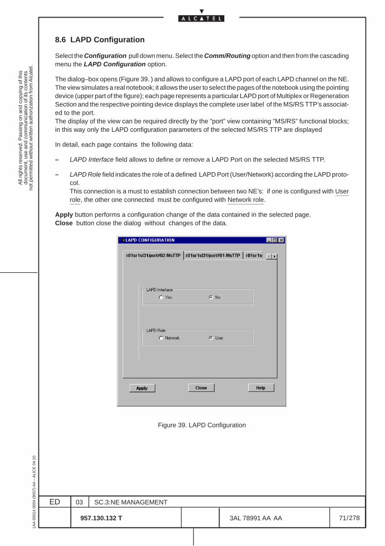
All
right
s re
serv
ed. P
assi
ng o
n an
d co
pyin
g of
this
docu
men
t, us
e an
d co
mm
unic
atio
n of
its
cont
ents
not p
erm
itted
with
out w
ritte
n au
thor
izat
ion
from
Alc
atel
.
ED
1AA
000
14 0
004
(900
7) A
4 –
ALI
CE
04.
10
71
03
957.130.132 T
SC.3:NE MANAGEMENT
/3AL 78991 AA AA
278
278
8.6 LAPD Configuration
Select the Configuration pull down menu. Select the Comm/Routing option and then from the cascadingmenu the LAPD Configuration option.
The dialog–box opens (Figure 39. ) and allows to configure a LAPD port of each LAPD channel on the NE.The view simulates a real notebook; it allows the user to select the pages of the notebook using the pointingdevice (upper part of the figure); each page represents a particular LAPD port of Multiplex or RegenerationSection and the respective pointing device displays the complete user label of the MS/RS TTP’s associat-ed to the port.The display of the view can be required directly by the ”port” view containing ”MS/RS” functional blocks;in this way only the LAPD configuration parameters of the selected MS/RS TTP are displayed
In detail, each page contains the following data:
– LAPD Interface field allows to define or remove a LAPD Port on the selected MS/RS TTP.
– LAPD Role field indicates the role of a defined LAPD Port (User/Network) according the LAPD proto-col.This connection is a must to establish connection between two NE’s: if one is configured with Userrole, the other one connected must be configured with Network role.
Apply button performs a configuration change of the data contained in the selected page.Close button close the dialog without changes of the data.
Figure 39. LAPD Configuration
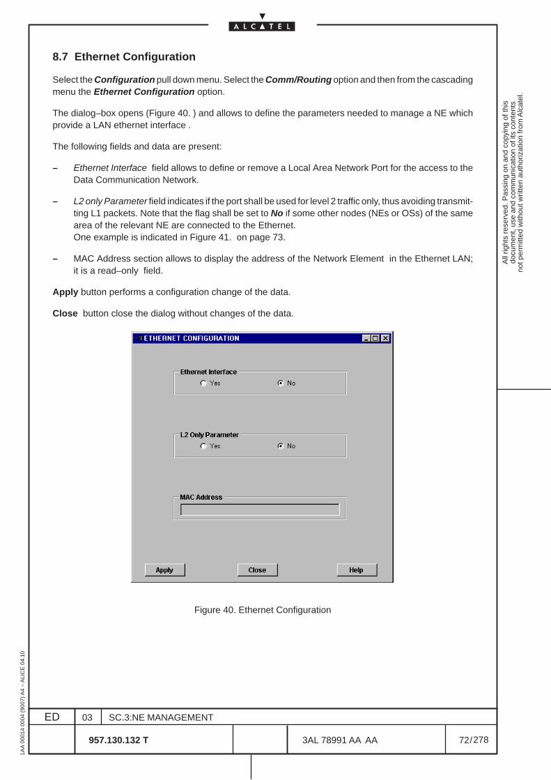
All
right
s re
serv
ed. P
assi
ng o
n an
d co
pyin
g of
this
docu
men
t, us
e an
d co
mm
unic
atio
n of
its
cont
ents
not p
erm
itted
with
out w
ritte
n au
thor
izat
ion
from
Alc
atel
.
ED
1AA
000
14 0
004
(900
7) A
4 –
ALI
CE
04.
10
72
03
957.130.132 T
SC.3:NE MANAGEMENT
/3AL 78991 AA AA
278
278
8.7 Ethernet Configuration
Select the Configuration pull down menu. Select the Comm/Routing option and then from the cascadingmenu the Ethernet Configuration option.
The dialog–box opens (Figure 40. ) and allows to define the parameters needed to manage a NE whichprovide a LAN ethernet interface .
The following fields and data are present:
– Ethernet Interface field allows to define or remove a Local Area Network Port for the access to theData Communication Network.
– L2 only Parameter field indicates if the port shall be used for level 2 traffic only, thus avoiding transmit-ting L1 packets. Note that the flag shall be set to No if some other nodes (NEs or OSs) of the samearea of the relevant NE are connected to the Ethernet.One example is indicated in Figure 41. on page 73.
– MAC Address section allows to display the address of the Network Element in the Ethernet LAN;it is a read–only field.
Apply button performs a configuration change of the data.
Close button close the dialog without changes of the data.
Figure 40. Ethernet Configuration

All
right
s re
serv
ed. P
assi
ng o
n an
d co
pyin
g of
this
docu
men
t, us
e an
d co
mm
unic
atio
n of
its
cont
ents
not p
erm
itted
with
out w
ritte
n au
thor
izat
ion
from
Alc
atel
.
ED
1AA
000
14 0
004
(900
7) A
4 –
ALI
CE
04.
10
73
03
957.130.132 T
SC.3:NE MANAGEMENT
/3AL 78991 AA AA
278
278
L2 L2
NENo
AREA 1
AREA 2
AREA 3
LAN
NENo
L2
NEYes
OS
Figure 41. Ethernet Configuration – L2 only parameter
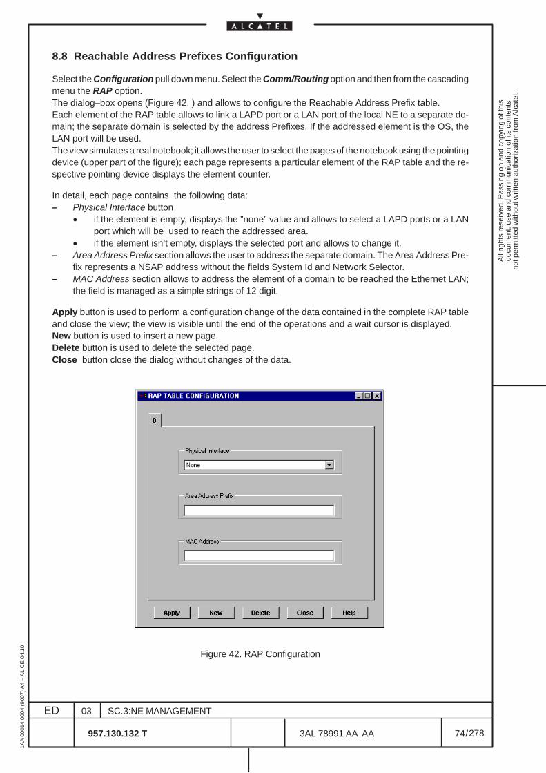
All
right
s re
serv
ed. P
assi
ng o
n an
d co
pyin
g of
this
docu
men
t, us
e an
d co
mm
unic
atio
n of
its
cont
ents
not p
erm
itted
with
out w
ritte
n au
thor
izat
ion
from
Alc
atel
.
ED
1AA
000
14 0
004
(900
7) A
4 –
ALI
CE
04.
10
74
03
957.130.132 T
SC.3:NE MANAGEMENT
/3AL 78991 AA AA
278
278
8.8 Reachable Address Prefixes Configuration
Select the Configuration pull down menu. Select the Comm/Routing option and then from the cascadingmenu the RAP option.The dialog–box opens (Figure 42. ) and allows to configure the Reachable Address Prefix table.Each element of the RAP table allows to link a LAPD port or a LAN port of the local NE to a separate do-main; the separate domain is selected by the address Prefixes. If the addressed element is the OS, theLAN port will be used.The view simulates a real notebook; it allows the user to select the pages of the notebook using the pointingdevice (upper part of the figure); each page represents a particular element of the RAP table and the re-spective pointing device displays the element counter.
In detail, each page contains the following data:– Physical Interface button
• if the element is empty, displays the ”none” value and allows to select a LAPD ports or a LANport which will be used to reach the addressed area.
• if the element isn’t empty, displays the selected port and allows to change it.– Area Address Prefix section allows the user to address the separate domain. The Area Address Pre-
fix represents a NSAP address without the fields System Id and Network Selector.– MAC Address section allows to address the element of a domain to be reached the Ethernet LAN;
the field is managed as a simple strings of 12 digit.
Apply button is used to perform a configuration change of the data contained in the complete RAP tableand close the view; the view is visible until the end of the operations and a wait cursor is displayed.New button is used to insert a new page.Delete button is used to delete the selected page.Close button close the dialog without changes of the data.
Figure 42. RAP Configuration
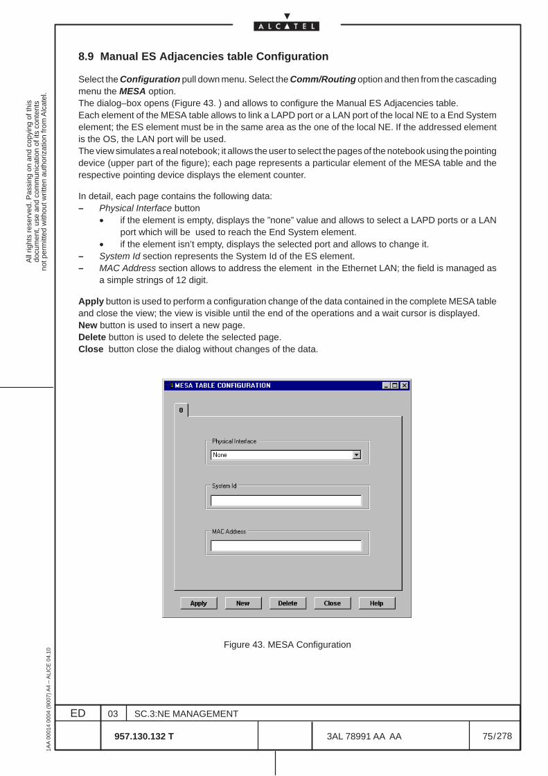
All
right
s re
serv
ed. P
assi
ng o
n an
d co
pyin
g of
this
docu
men
t, us
e an
d co
mm
unic
atio
n of
its
cont
ents
not p
erm
itted
with
out w
ritte
n au
thor
izat
ion
from
Alc
atel
.
ED
1AA
000
14 0
004
(900
7) A
4 –
ALI
CE
04.
10
75
03
957.130.132 T
SC.3:NE MANAGEMENT
/3AL 78991 AA AA
278
278
8.9 Manual ES Adjacencies table Configuration
Select the Configuration pull down menu. Select the Comm/Routing option and then from the cascadingmenu the MESA option.The dialog–box opens (Figure 43. ) and allows to configure the Manual ES Adjacencies table.Each element of the MESA table allows to link a LAPD port or a LAN port of the local NE to a End Systemelement; the ES element must be in the same area as the one of the local NE. If the addressed elementis the OS, the LAN port will be used.The view simulates a real notebook; it allows the user to select the pages of the notebook using the pointingdevice (upper part of the figure); each page represents a particular element of the MESA table and therespective pointing device displays the element counter.
In detail, each page contains the following data:– Physical Interface button
• if the element is empty, displays the ”none” value and allows to select a LAPD ports or a LANport which will be used to reach the End System element.
• if the element isn’t empty, displays the selected port and allows to change it.– System Id section represents the System Id of the ES element.– MAC Address section allows to address the element in the Ethernet LAN; the field is managed as
a simple strings of 12 digit.
Apply button is used to perform a configuration change of the data contained in the complete MESA tableand close the view; the view is visible until the end of the operations and a wait cursor is displayed.New button is used to insert a new page.Delete button is used to delete the selected page.Close button close the dialog without changes of the data.
Figure 43. MESA Configuration

All
right
s re
serv
ed. P
assi
ng o
n an
d co
pyin
g of
this
docu
men
t, us
e an
d co
mm
unic
atio
n of
its
cont
ents
not p
erm
itted
with
out w
ritte
n au
thor
izat
ion
from
Alc
atel
.
ED
1AA
000
14 0
004
(900
7) A
4 –
ALI
CE
04.
10
76
03
957.130.132 T
SC.3:NE MANAGEMENT
/3AL 78991 AA AA
278
278
All
right
s re
serv
ed. P
assi
ng o
n an
d co
pyin
g of
this
docu
men
t, us
e an
d co
mm
unic
atio
n of
its
cont
ents
not p
erm
itted
with
out w
ritte
n au
thor
izat
ion
from
Alc
atel
.
ED
1AA
000
14 0
004
(900
7) A
4 –
ALI
CE
04.
10
77
03
957.130.132 T
SC.3:NE MANAGEMENT
/3AL 78991 AA AA
278
278
9 EQUIPMENT MANAGEMENT
9.1 Introduction and navigation
This section deals mainly with the setting and changing of the boards present on the Equipment andundertaking board protection operations.
Using the menu options, select the Equipment option from the View pull down menu
The first level of the “Equipment Overview” representation will be displayed directly into the current window(see the following figure).The Equipment Overview enables a fast navigation through all levels of the equipment hierarchy.Navigation is done from higher to lower levels.The NE hierarchy is organized in the following way: rack> subrack > board > port > TP
The navigation through different levels of the NE hierarchy is performed by double clicking on the objects:
• the first level shows the rack level of the Equipment view (see Figure 44. );
• double clicking on it the subrack level of the Equipment view is reached (see Figure 45. );
• further, by double clicking on a board body, the board level of the Equipment view can bereached (as described in chapter 10 on page 89).
• further, by double clicking on a port body contained in the board, the port level of the Equipmentview can be reached (as described in chapter 11 on page 95). The port view displays the innerTPs.
• it is possible to go back to the upper level of representation by pressing the <ESC> key on thekeyboard; or to go back to the previous view, by selecting the Previous option from the Viewsmenu.
N.B. Selecting in the first level of the Equipment view ( rack level, Figure 44. ) the Show supportingequipment option from the Equipment menu, the Equipment level view of Figure 46. ispresented.
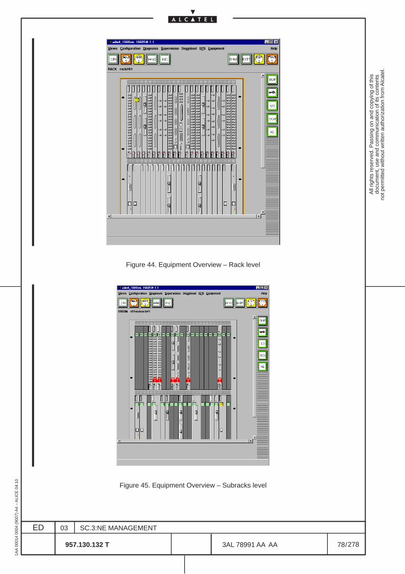
All
right
s re
serv
ed. P
assi
ng o
n an
d co
pyin
g of
this
docu
men
t, us
e an
d co
mm
unic
atio
n of
its
cont
ents
not p
erm
itted
with
out w
ritte
n au
thor
izat
ion
from
Alc
atel
.
ED
1AA
000
14 0
004
(900
7) A
4 –
ALI
CE
04.
10
78
03
957.130.132 T
SC.3:NE MANAGEMENT
/3AL 78991 AA AA
278
278
Figure 44. Equipment Overview – Rack level
Figure 45. Equipment Overview – Subracks level
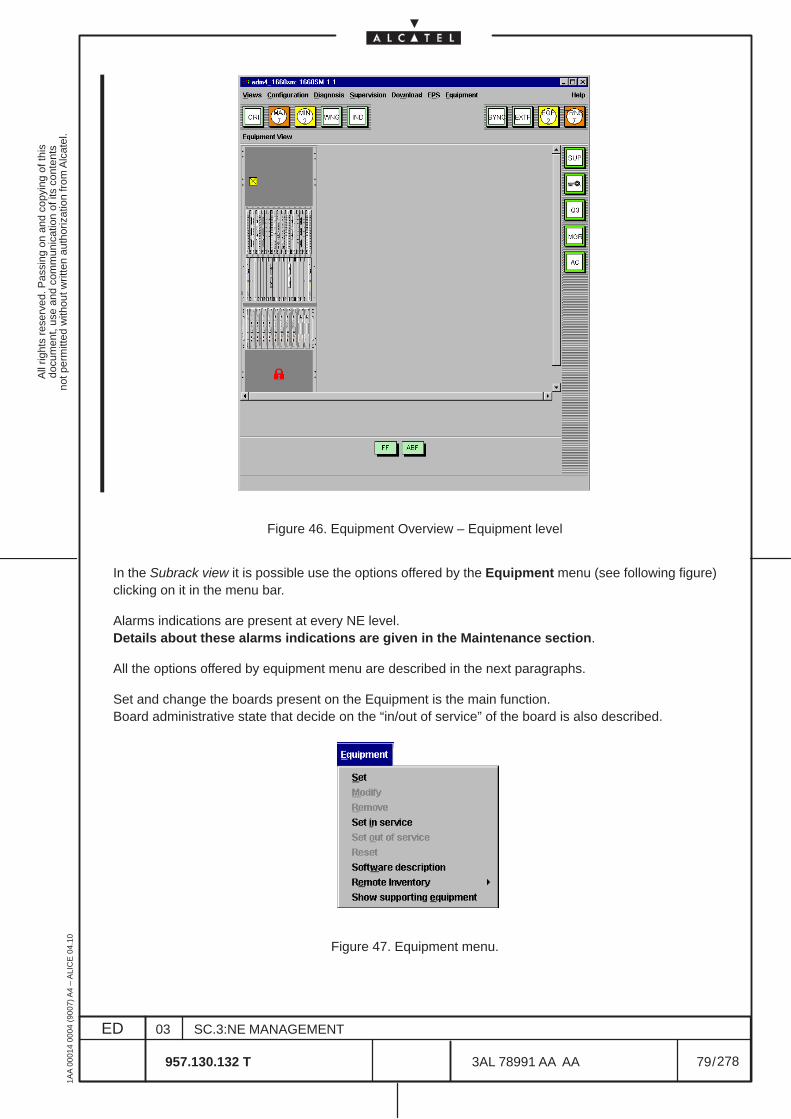
All
right
s re
serv
ed. P
assi
ng o
n an
d co
pyin
g of
this
docu
men
t, us
e an
d co
mm
unic
atio
n of
its
cont
ents
not p
erm
itted
with
out w
ritte
n au
thor
izat
ion
from
Alc
atel
.
ED
1AA
000
14 0
004
(900
7) A
4 –
ALI
CE
04.
10
79
03
957.130.132 T
SC.3:NE MANAGEMENT
/3AL 78991 AA AA
278
278
Figure 46. Equipment Overview – Equipment level
In the Subrack view it is possible use the options offered by the Equipment menu (see following figure)clicking on it in the menu bar.
Alarms indications are present at every NE level.Details about these alarms indications are given in the Maintenance section.
All the options offered by equipment menu are described in the next paragraphs.
Set and change the boards present on the Equipment is the main function.Board administrative state that decide on the “in/out of service” of the board is also described.
Figure 47. Equipment menu.
All
right
s re
serv
ed. P
assi
ng o
n an
d co
pyin
g of
this
docu
men
t, us
e an
d co
mm
unic
atio
n of
its
cont
ents
not p
erm
itted
with
out w
ritte
n au
thor
izat
ion
from
Alc
atel
.
ED
1AA
000
14 0
004
(900
7) A
4 –
ALI
CE
04.
10
80
03
957.130.132 T
SC.3:NE MANAGEMENT
/3AL 78991 AA AA
278
278
Equipment setting operation are defined according the following sequences:
– configuration of a new board• Configure the board using the option “Set”
– change of board type• “Set out of service” the board• Configure the board using the option “Set”
– remove a board• “Set out of service” the board• “Remove” the board.
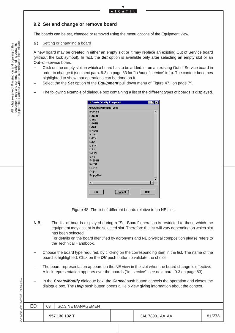
All
right
s re
serv
ed. P
assi
ng o
n an
d co
pyin
g of
this
docu
men
t, us
e an
d co
mm
unic
atio
n of
its
cont
ents
not p
erm
itted
with
out w
ritte
n au
thor
izat
ion
from
Alc
atel
.
ED
1AA
000
14 0
004
(900
7) A
4 –
ALI
CE
04.
10
81
03
957.130.132 T
SC.3:NE MANAGEMENT
/3AL 78991 AA AA
278
278
9.2 Set and change or remove board
The boards can be set, changed or removed using the menu options of the Equipment view.
a ) Setting or changing a board
A new board may be created in either an empty slot or it may replace an existing Out of Service board(without the lock symbol). In fact, the Set option is available only after selecting an empty slot or anOut–of–service board.– Click on the empty slot in which a board has to be added, or on an existing Out of Service board in
order to change it (see next para. 9.3 on page 83 for “in /out of service” info). The contour becomeshighlighted to show that operations can be done on it.
– Select the the Set option of the Equipment pull down menu of Figure 47. on page 79.
– The following example of dialogue box containing a list of the different types of boards is displayed.
Figure 48. The list of different boards relative to an NE slot.
N.B. The list of boards displayed during a ”Set Board” operation is restricted to those which theequipment may accept in the selected slot. Therefore the list will vary depending on which slothas been selected.For details on the board identified by acronyms and NE physical composition please refers tothe Technical Handbook.
– Choose the board type required, by clicking on the corresponding item in the list. The name of theboard is highlighted. Click on the OK push button to validate the choice.
– The board representation appears on the NE view in the slot when the board change is effective.A lock representation appears over the boards (”in–service”, see next para. 9.3 on page 83)
– In the Create/Modify dialogue box, the Cancel push button cancels the operation and closes thedialogue box. The Help push button opens a Help view giving information about the context.
All
right
s re
serv
ed. P
assi
ng o
n an
d co
pyin
g of
this
docu
men
t, us
e an
d co
mm
unic
atio
n of
its
cont
ents
not p
erm
itted
with
out w
ritte
n au
thor
izat
ion
from
Alc
atel
.
ED
1AA
000
14 0
004
(900
7) A
4 –
ALI
CE
04.
10
82
03
957.130.132 T
SC.3:NE MANAGEMENT
/3AL 78991 AA AA
278
278
b ) Removing a board
– Click on the board to remove (Out of Service board, as for next para. 9.3 on page 83).The outline of the slot becomes highlighted. This indicates that the board is selected and thatoperations can be done on the slot.
– If the slot you are working on is already empty no name appears under the slot.
– Select the Remove option the Equipment pull down menu of Figure 47. on page 79.
– From the confirmation dialogue box that opens you can confirm or cancel the ”Remove Board” operation.
c ) Modify a board
N.B. This procedure can be done to replace an existing optical module with another of differenttype without previously remove it.
– Click on the optical module to replace. The outline of the slot becomes highlighted to show thatoperation can be done on it.
– Select the Modify option of the Equipment pull down menu of Figure 47. on page 79 .
– A dialog box containing a list of different types of optical module is displayed.
– Chose the optical module type required by clicking on the corresponding item in the list; the nameof the module is highlighted.
– Click on OK push button to validate the choice.
– The board representation appears on the N.E. view in the slot when the board change is effective.A padlock representation appears over the board.
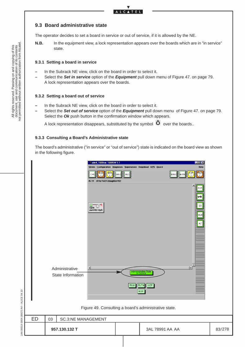
All
right
s re
serv
ed. P
assi
ng o
n an
d co
pyin
g of
this
docu
men
t, us
e an
d co
mm
unic
atio
n of
its
cont
ents
not p
erm
itted
with
out w
ritte
n au
thor
izat
ion
from
Alc
atel
.
ED
1AA
000
14 0
004
(900
7) A
4 –
ALI
CE
04.
10
83
03
957.130.132 T
SC.3:NE MANAGEMENT
/3AL 78991 AA AA
278
278
9.3 Board administrative state
The operator decides to set a board in service or out of service, if it is allowed by the NE.
N.B. In the equipment view, a lock representation appears over the boards which are in ”in service”state.
9.3.1 Setting a board in service
– In the Subrack NE view, click on the board in order to select it.– Select the Set in service option of the Equipment pull down menu of Figure 47. on page 79.
A lock representation appears over the boards.
9.3.2 Setting a board out of service
– In the Subrack NE view, click on the board in order to select it.– Select the Set out of service option of the Equipment pull down menu of Figure 47. on page 79.
Select the Ok push button in the confirmation window which appears.
A lock representation disappears, substituted by the symbol over the boards..
9.3.3 Consulting a Board’s Administrative state
The board’s administrative (”in service” or “out of service”) state is indicated on the board view as shownin the following figure.
Administrative
State Information
Figure 49. Consulting a board’s administrative state.
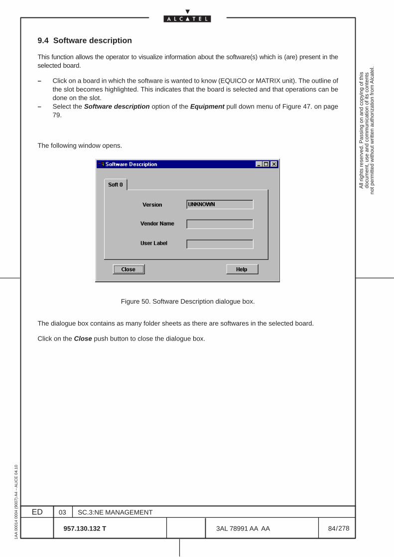
All
right
s re
serv
ed. P
assi
ng o
n an
d co
pyin
g of
this
docu
men
t, us
e an
d co
mm
unic
atio
n of
its
cont
ents
not p
erm
itted
with
out w
ritte
n au
thor
izat
ion
from
Alc
atel
.
ED
1AA
000
14 0
004
(900
7) A
4 –
ALI
CE
04.
10
84
03
957.130.132 T
SC.3:NE MANAGEMENT
/3AL 78991 AA AA
278
278
9.4 Software description
This function allows the operator to visualize information about the software(s) which is (are) present in theselected board.
– Click on a board in which the software is wanted to know (EQUICO or MATRIX unit). The outline ofthe slot becomes highlighted. This indicates that the board is selected and that operations can bedone on the slot.
– Select the Software description option of the Equipment pull down menu of Figure 47. on page79.
The following window opens.
Figure 50. Software Description dialogue box.
The dialogue box contains as many folder sheets as there are softwares in the selected board.
Click on the Close push button to close the dialogue box.
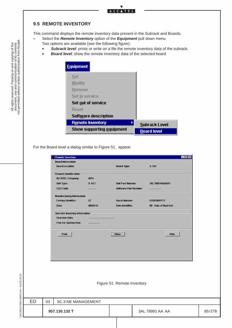
All
right
s re
serv
ed. P
assi
ng o
n an
d co
pyin
g of
this
docu
men
t, us
e an
d co
mm
unic
atio
n of
its
cont
ents
not p
erm
itted
with
out w
ritte
n au
thor
izat
ion
from
Alc
atel
.
ED
1AA
000
14 0
004
(900
7) A
4 –
ALI
CE
04.
10
85
03
957.130.132 T
SC.3:NE MANAGEMENT
/3AL 78991 AA AA
278
278
9.5 REMOTE INVENTORY
This command displays the remote inventory data present in the Subrack and Boards.– Select the Remote Inventory option of the Equipment pull down menu.
Two options are available (see the following figure):• Subrack level: prints or write on a file the remote inventory data of the subrack.• Board level: show the remote inventory data of the selected board
For the Board level a dialog similar to Figure 51. appear.
Figure 51. Remote Inventory
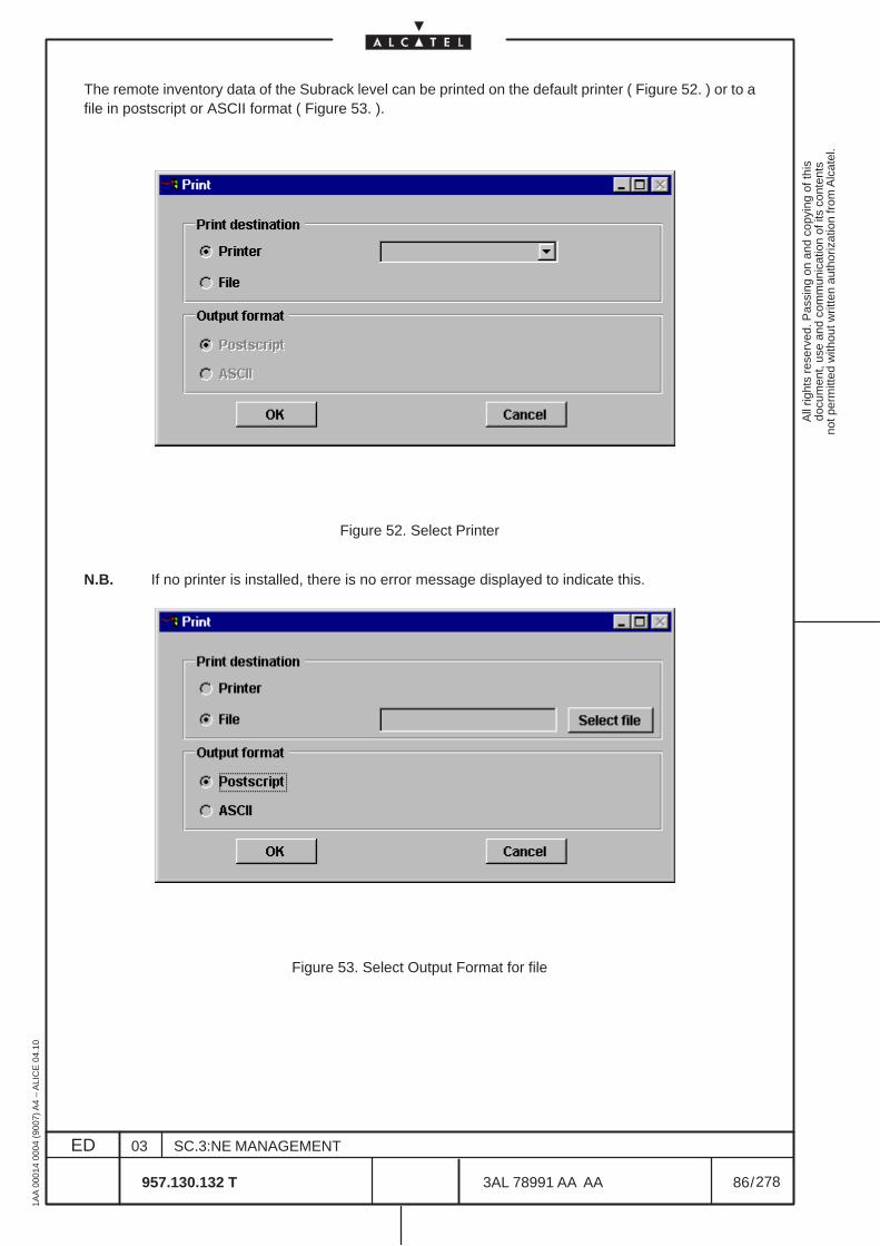
All
right
s re
serv
ed. P
assi
ng o
n an
d co
pyin
g of
this
docu
men
t, us
e an
d co
mm
unic
atio
n of
its
cont
ents
not p
erm
itted
with
out w
ritte
n au
thor
izat
ion
from
Alc
atel
.
ED
1AA
000
14 0
004
(900
7) A
4 –
ALI
CE
04.
10
86
03
957.130.132 T
SC.3:NE MANAGEMENT
/3AL 78991 AA AA
278
278
The remote inventory data of the Subrack level can be printed on the default printer ( Figure 52. ) or to afile in postscript or ASCII format ( Figure 53. ).
Figure 52. Select Printer
N.B. If no printer is installed, there is no error message displayed to indicate this.
Figure 53. Select Output Format for file
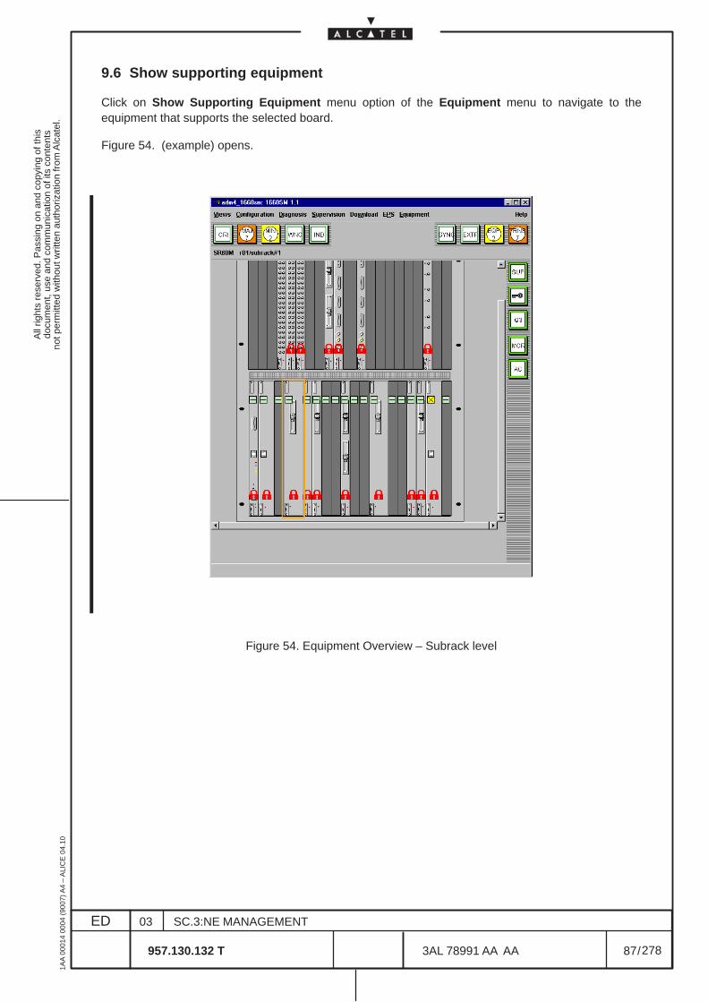
All
right
s re
serv
ed. P
assi
ng o
n an
d co
pyin
g of
this
docu
men
t, us
e an
d co
mm
unic
atio
n of
its
cont
ents
not p
erm
itted
with
out w
ritte
n au
thor
izat
ion
from
Alc
atel
.
ED
1AA
000
14 0
004
(900
7) A
4 –
ALI
CE
04.
10
87
03
957.130.132 T
SC.3:NE MANAGEMENT
/3AL 78991 AA AA
278
278
9.6 Show supporting equipment
Click on Show Supporting Equipment menu option of the Equipment menu to navigate to theequipment that supports the selected board.
Figure 54. (example) opens.
Figure 54. Equipment Overview – Subrack level

All
right
s re
serv
ed. P
assi
ng o
n an
d co
pyin
g of
this
docu
men
t, us
e an
d co
mm
unic
atio
n of
its
cont
ents
not p
erm
itted
with
out w
ritte
n au
thor
izat
ion
from
Alc
atel
.
ED
1AA
000
14 0
004
(900
7) A
4 –
ALI
CE
04.
10
88
03
957.130.132 T
SC.3:NE MANAGEMENT
/3AL 78991 AA AA
278
278
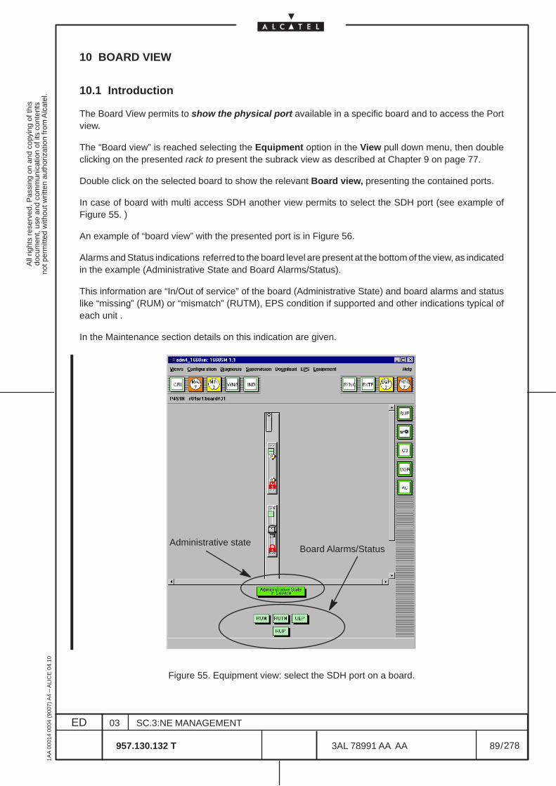
All
right
s re
serv
ed. P
assi
ng o
n an
d co
pyin
g of
this
docu
men
t, us
e an
d co
mm
unic
atio
n of
its
cont
ents
not p
erm
itted
with
out w
ritte
n au
thor
izat
ion
from
Alc
atel
.
ED
1AA
000
14 0
004
(900
7) A
4 –
ALI
CE
04.
10
89
03
957.130.132 T
SC.3:NE MANAGEMENT
/3AL 78991 AA AA
278
278
10 BOARD VIEW
10.1 Introduction
The Board View permits to show the physical port available in a specific board and to access the Portview.
The “Board view” is reached selecting the Equipment option in the View pull down menu, then doubleclicking on the presented rack to present the subrack view as described at Chapter 9 on page 77.
Double click on the selected board to show the relevant Board view, presenting the contained ports.
In case of board with multi access SDH another view permits to select the SDH port (see example ofFigure 55. )
An example of “board view” with the presented port is in Figure 56.
Alarms and Status indications referred to the board level are present at the bottom of the view, as indicatedin the example (Administrative State and Board Alarms/Status).
This information are “In/Out of service” of the board (Administrative State) and board alarms and statuslike “missing” (RUM) or “mismatch” (RUTM), EPS condition if supported and other indications typical ofeach unit .
In the Maintenance section details on this indication are given.
Administrative stateBoard Alarms/Status
Figure 55. Equipment view: select the SDH port on a board.

All
right
s re
serv
ed. P
assi
ng o
n an
d co
pyin
g of
this
docu
men
t, us
e an
d co
mm
unic
atio
n of
its
cont
ents
not p
erm
itted
with
out w
ritte
n au
thor
izat
ion
from
Alc
atel
.
ED
1AA
000
14 0
004
(900
7) A
4 –
ALI
CE
04.
10
90
03
957.130.132 T
SC.3:NE MANAGEMENT
/3AL 78991 AA AA
278
278
Figure 56. Example of a Board View
A port type is described with a board rectangular view and a port identification.
The port identification is usually internal to the rectangular board (see Figure 57. one example of opticalport).
Figure 57. Example of a Port identification and alarm synthesis
The following information is available:
– type of port (name)– state of port (alarm status synthesis)– symbol of the port
The operator is provided with a representation of the port alarm synthesis on each port.
The messages displayed at the top view provide port denomination.
The messages displayed at the bottom provide information about Board alarms.
A message under the mouse facility provides the name and the port type or the alarms name. A messageappears in the message area in the bottom left corner of the view.
By double clicking on a board view, it is also possible open the corresponding port view (see chapter 11on page 95).
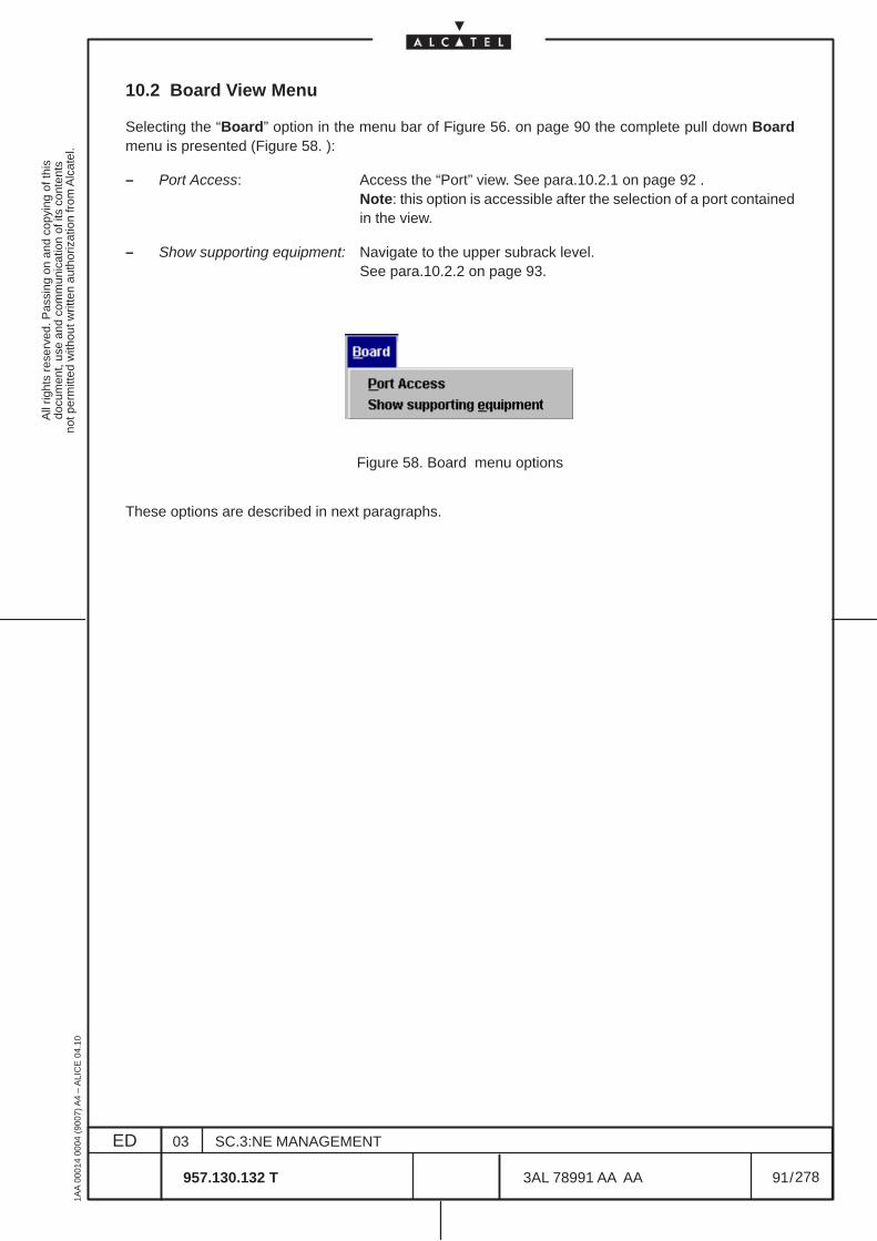
All
right
s re
serv
ed. P
assi
ng o
n an
d co
pyin
g of
this
docu
men
t, us
e an
d co
mm
unic
atio
n of
its
cont
ents
not p
erm
itted
with
out w
ritte
n au
thor
izat
ion
from
Alc
atel
.
ED
1AA
000
14 0
004
(900
7) A
4 –
ALI
CE
04.
10
91
03
957.130.132 T
SC.3:NE MANAGEMENT
/3AL 78991 AA AA
278
278
10.2 Board View Menu
Selecting the “Board” option in the menu bar of Figure 56. on page 90 the complete pull down Boardmenu is presented (Figure 58. ):
– Port Access: Access the “Port” view. See para.10.2.1 on page 92 .Note: this option is accessible after the selection of a port containedin the view.
– Show supporting equipment: Navigate to the upper subrack level.See para.10.2.2 on page 93.
Figure 58. Board menu options
These options are described in next paragraphs.
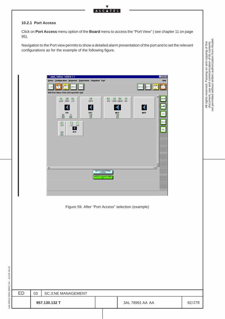
All
right
s re
serv
ed. P
assi
ng o
n an
d co
pyin
g of
this
docu
men
t, us
e an
d co
mm
unic
atio
n of
its
cont
ents
not p
erm
itted
with
out w
ritte
n au
thor
izat
ion
from
Alc
atel
.
ED
1AA
000
14 0
004
(900
7) A
4 –
ALI
CE
04.
10
92
03
957.130.132 T
SC.3:NE MANAGEMENT
/3AL 78991 AA AA
278
278
10.2.1 Port Access
Click on Port Access menu option of the Board menu to access the “Port View” ( see chapter 11 on page95).
Navigation to the Port view permits to show a detailed alarm presentation of the port and to set the relevantconfigurations as for the example of the following figure.
Figure 59. After “Port Access” selection (example)
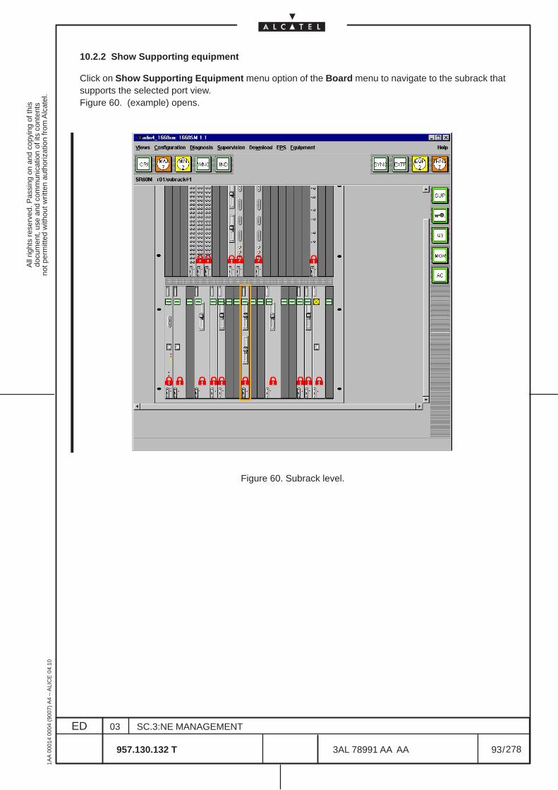
All
right
s re
serv
ed. P
assi
ng o
n an
d co
pyin
g of
this
docu
men
t, us
e an
d co
mm
unic
atio
n of
its
cont
ents
not p
erm
itted
with
out w
ritte
n au
thor
izat
ion
from
Alc
atel
.
ED
1AA
000
14 0
004
(900
7) A
4 –
ALI
CE
04.
10
93
03
957.130.132 T
SC.3:NE MANAGEMENT
/3AL 78991 AA AA
278
278
10.2.2 Show Supporting equipment
Click on Show Supporting Equipment menu option of the Board menu to navigate to the subrack thatsupports the selected port view.Figure 60. (example) opens.
Figure 60. Subrack level.

All
right
s re
serv
ed. P
assi
ng o
n an
d co
pyin
g of
this
docu
men
t, us
e an
d co
mm
unic
atio
n of
its
cont
ents
not p
erm
itted
with
out w
ritte
n au
thor
izat
ion
from
Alc
atel
.
ED
1AA
000
14 0
004
(900
7) A
4 –
ALI
CE
04.
10
94
03
957.130.132 T
SC.3:NE MANAGEMENT
/3AL 78991 AA AA
278
278
All
right
s re
serv
ed. P
assi
ng o
n an
d co
pyin
g of
this
docu
men
t, us
e an
d co
mm
unic
atio
n of
its
cont
ents
not p
erm
itted
with
out w
ritte
n au
thor
izat
ion
from
Alc
atel
.
ED
1AA
000
14 0
004
(900
7) A
4 –
ALI
CE
04.
10
95
03
957.130.132 T
SC.3:NE MANAGEMENT
/3AL 78991 AA AA
278
278
11 PORT VIEW
11.1 Introduction
This section describes the operations necessary for the consultation, modification and configuration ofeach port.
The Port View permits to set and show the transmission resources (i.e. the Termination Point, TP) referredto the specific Port; it permits to check the detailed alarms presented by each TP of the Port, and theavailable menu permits to configure the port, (many setting options listed in the port menu are commonwith the “Transmission” view).In these views are presented only the TP specific of the port.
The menu differs according the port type (SDH, PDH, HOA).
The Port View can be accessed from the Equipment or Transmission Views.
The “Port view” is reached selecting the Equipment option in the View pull down menu then doubleclicking on the presented rack/subrack to present the subrack view, as described in chapter 9 on page 77.Double clicking on the selected board the relevant Board view is available presenting the ports (seechapter 10 on page 89).By double clicking on a board view, the corresponding port view is opened (see Figure 61. ).
The “Port view” is also reached selecting the Transmission option in the View pull down menu.
Then the Add TP option of the Transmission menu permits to select and confirm a TP (see the descriptionat para. 14.5 on page 141).
On the transmission view which appears select the TP and on the Transmission menu select theNavigate to a port view option.The HOA port view can only be reached from the Transmission view, selecting a VC or TU TP.
From the Port view It is possible to Navigate to Transmission view.
The port types contain the following TP:
• SDH port: Electrical or Optical SPI TTP, RS TTP, prot TTP (MSP TTP), AU4 CTP, Trail Monitor(only with enabled POM)
• PDH port: PPI TTP, En CTP, VCn TTP
• HOA port: VC4 TTP, TUG3, TUG2, TU3, TU12, Trail Monitoring (only with enabled POM)
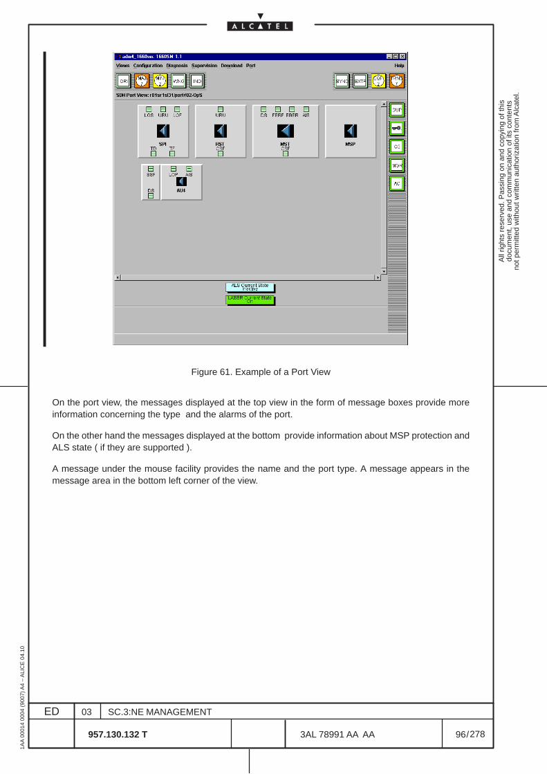
All
right
s re
serv
ed. P
assi
ng o
n an
d co
pyin
g of
this
docu
men
t, us
e an
d co
mm
unic
atio
n of
its
cont
ents
not p
erm
itted
with
out w
ritte
n au
thor
izat
ion
from
Alc
atel
.
ED
1AA
000
14 0
004
(900
7) A
4 –
ALI
CE
04.
10
96
03
957.130.132 T
SC.3:NE MANAGEMENT
/3AL 78991 AA AA
278
278
Figure 61. Example of a Port View
On the port view, the messages displayed at the top view in the form of message boxes provide moreinformation concerning the type and the alarms of the port.
On the other hand the messages displayed at the bottom provide information about MSP protection andALS state ( if they are supported ).
A message under the mouse facility provides the name and the port type. A message appears in themessage area in the bottom left corner of the view.
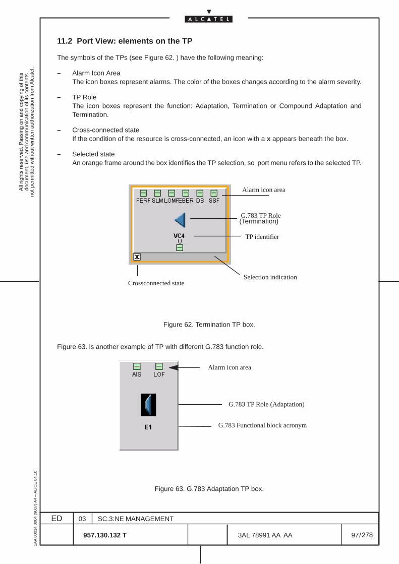
All
right
s re
serv
ed. P
assi
ng o
n an
d co
pyin
g of
this
docu
men
t, us
e an
d co
mm
unic
atio
n of
its
cont
ents
not p
erm
itted
with
out w
ritte
n au
thor
izat
ion
from
Alc
atel
.
ED
1AA
000
14 0
004
(900
7) A
4 –
ALI
CE
04.
10
97
03
957.130.132 T
SC.3:NE MANAGEMENT
/3AL 78991 AA AA
278
278
11.2 Port View: elements on the TP
The symbols of the TPs (see Figure 62. ) have the following meaning:
– Alarm Icon AreaThe icon boxes represent alarms. The color of the boxes changes according to the alarm severity.
– TP RoleThe icon boxes represent the function: Adaptation, Termination or Compound Adaptation andTermination.
– Cross-connected stateIf the condition of the resource is cross-connected, an icon with a x appears beneath the box.
– Selected stateAn orange frame around the box identifies the TP selection, so port menu refers to the selected TP.
Alarm icon area
TP identifier
Crossconnected stateSelection indication
G.783 TP Role (Termination)
Figure 62. Termination TP box.
Figure 63. is another example of TP with different G.783 function role.
Alarm icon area
G.783 Functional block acronym
G.783 TP Role (Adaptation)
Figure 63. G.783 Adaptation TP box.
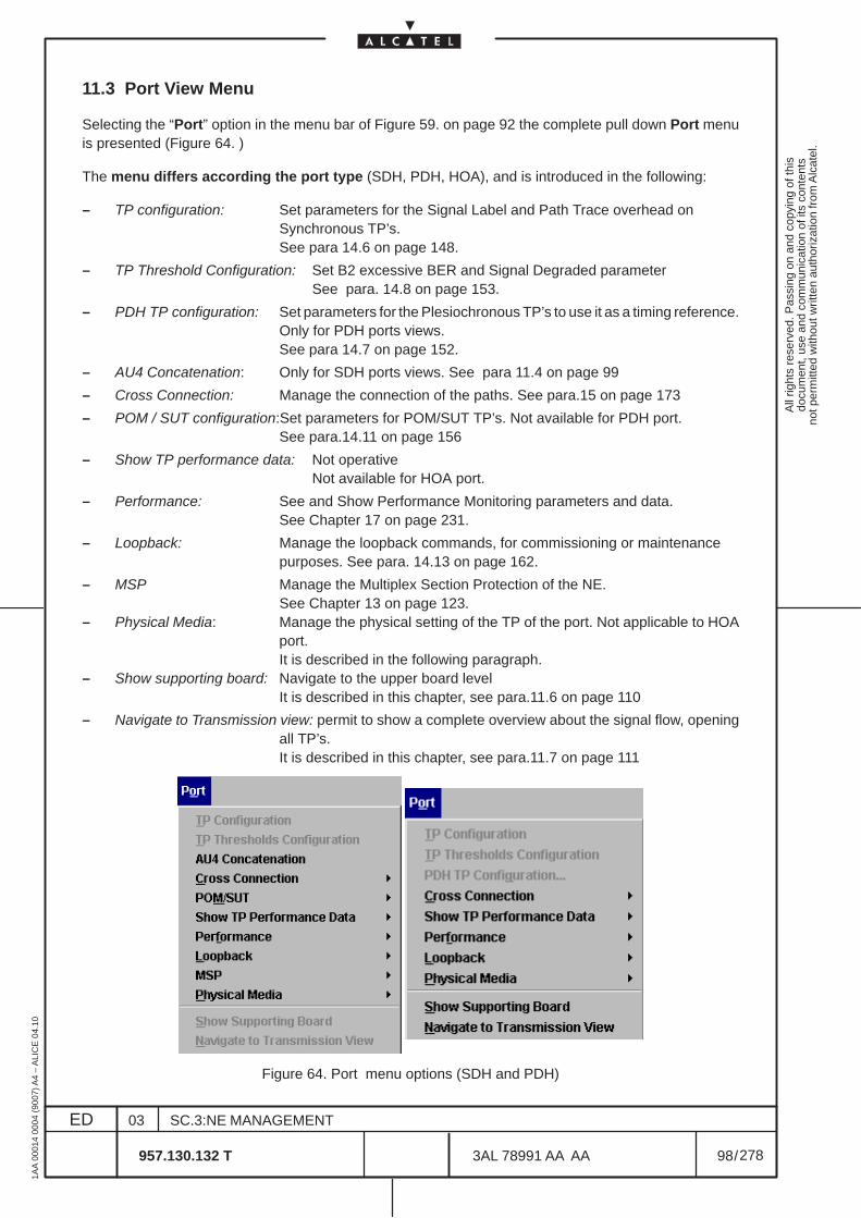
All
right
s re
serv
ed. P
assi
ng o
n an
d co
pyin
g of
this
docu
men
t, us
e an
d co
mm
unic
atio
n of
its
cont
ents
not p
erm
itted
with
out w
ritte
n au
thor
izat
ion
from
Alc
atel
.
ED
1AA
000
14 0
004
(900
7) A
4 –
ALI
CE
04.
10
98
03
957.130.132 T
SC.3:NE MANAGEMENT
/3AL 78991 AA AA
278
278
11.3 Port View Menu
Selecting the “Port” option in the menu bar of Figure 59. on page 92 the complete pull down Port menuis presented (Figure 64. )
The menu differs according the port type (SDH, PDH, HOA), and is introduced in the following:
– TP configuration: Set parameters for the Signal Label and Path Trace overhead onSynchronous TP’s.See para 14.6 on page 148.
– TP Threshold Configuration: Set B2 excessive BER and Signal Degraded parameterSee para. 14.8 on page 153.
– PDH TP configuration: Set parameters for the Plesiochronous TP’s to use it as a timing reference.Only for PDH ports views.See para 14.7 on page 152.
– AU4 Concatenation: Only for SDH ports views. See para 11.4 on page 99
– Cross Connection: Manage the connection of the paths. See para.15 on page 173
– POM / SUT configuration:Set parameters for POM/SUT TP’s. Not available for PDH port.See para.14.11 on page 156
– Show TP performance data: Not operativeNot available for HOA port.
– Performance: See and Show Performance Monitoring parameters and data.See Chapter 17 on page 231.
– Loopback: Manage the loopback commands, for commissioning or maintenancepurposes. See para. 14.13 on page 162.
– MSP Manage the Multiplex Section Protection of the NE.See Chapter 13 on page 123.
– Physical Media: Manage the physical setting of the TP of the port. Not applicable to HOAport.It is described in the following paragraph.
– Show supporting board: Navigate to the upper board levelIt is described in this chapter, see para.11.6 on page 110
– Navigate to Transmission view: permit to show a complete overview about the signal flow, openingall TP’s.It is described in this chapter, see para.11.7 on page 111
Figure 64. Port menu options (SDH and PDH)
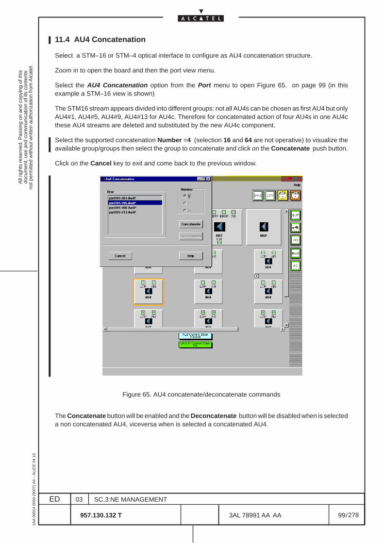
All
right
s re
serv
ed. P
assi
ng o
n an
d co
pyin
g of
this
docu
men
t, us
e an
d co
mm
unic
atio
n of
its
cont
ents
not p
erm
itted
with
out w
ritte
n au
thor
izat
ion
from
Alc
atel
.
ED
1AA
000
14 0
004
(900
7) A
4 –
ALI
CE
04.
10
99
03
957.130.132 T
SC.3:NE MANAGEMENT
/3AL 78991 AA AA
278
278
11.4 AU4 Concatenation
Select a STM–16 or STM–4 optical interface to configure as AU4 concatenation structure.
Zoom in to open the board and then the port view menu.
Select the AU4 Concatenation option from the Port menu to open Figure 65. on page 99 (in thisexample a STM–16 view is shown)
The STM16 stream appears divided into different groups: not all AU4s can be chosen as first AU4 but onlyAU4#1, AU4#5, AU4#9, AU4#13 for AU4c. Therefore for concatenated action of four AU4s in one AU4cthese AU4 streams are deleted and substituted by the new AU4c component.
Select the supported concatenation Number =4 (selection 16 and 64 are not operative) to visualize theavailable group/groups then select the group to concatenate and click on the Concatenate push button.
Click on the Cancel key to exit and come back to the previous window.
Figure 65. AU4 concatenate/deconcatenate commands
The Concatenate button will be enabled and the Deconcatenate button will be disabled when is selecteda non concatenated AU4, viceversa when is selected a concatenated AU4.

All
right
s re
serv
ed. P
assi
ng o
n an
d co
pyin
g of
this
docu
men
t, us
e an
d co
mm
unic
atio
n of
its
cont
ents
not p
erm
itted
with
out w
ritte
n au
thor
izat
ion
from
Alc
atel
.
ED
1AA
000
14 0
004
(900
7) A
4 –
ALI
CE
04.
10
100
03
957.130.132 T
SC.3:NE MANAGEMENT
/3AL 78991 AA AA
278
278
Figure 66. Example of a concatenated AU4 transmission view
The port view represented in Figure 66. shows an STM16 interface with four AU4 concatenated in oneAU4c. The AU4c appears as a single icon that has the same size of the actual AU4 blocks. The AU4cstreams support the Alarm synthesis, Cross–Connection states and Performance Monitoring informationas standard AU4 streams.
To deconcatenate an AU4c select again the “AU4 Concatenation” option in the Port View menu and thenselect the AU4c to deconcatenate (see Figure 67. ). Click on the Deconcatenate push button to applythe command or on Cancel to exit.
Figure 67. Example of a concatenated AU4c
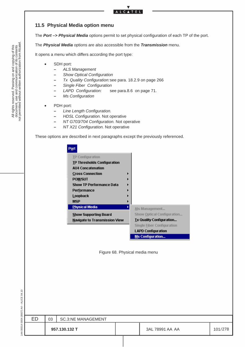
All
right
s re
serv
ed. P
assi
ng o
n an
d co
pyin
g of
this
docu
men
t, us
e an
d co
mm
unic
atio
n of
its
cont
ents
not p
erm
itted
with
out w
ritte
n au
thor
izat
ion
from
Alc
atel
.
ED
1AA
000
14 0
004
(900
7) A
4 –
ALI
CE
04.
10
101
03
957.130.132 T
SC.3:NE MANAGEMENT
/3AL 78991 AA AA
278
278
11.5 Physical Media option menu
The Port –> Physical Media options permit to set physical configuration of each TP of the port.
The Physical Media options are also accessible from the Transmission menu.
It opens a menu which differs according the port type:
• SDH port:– ALS Management– Show Optical Configuration– Tx Quality Configuration:see para. 18.2.9 on page 266– Single Fiber Configuration– LAPD Configuration: see para.8.6 on page 71.– Ms Configuration
• PDH port:– Line Length Configuration.– HDSL Configuration. Not operative– NT G703/704 Configuration. Not operative– NT X21 Configuration. Not operative
These options are described in next paragraphs except the previously referenced.
Figure 68. Physical media menu
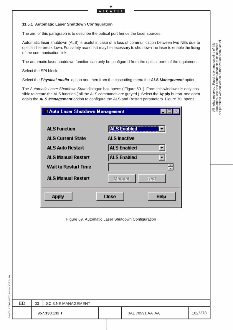
All
right
s re
serv
ed. P
assi
ng o
n an
d co
pyin
g of
this
docu
men
t, us
e an
d co
mm
unic
atio
n of
its
cont
ents
not p
erm
itted
with
out w
ritte
n au
thor
izat
ion
from
Alc
atel
.
ED
1AA
000
14 0
004
(900
7) A
4 –
ALI
CE
04.
10
102
03
957.130.132 T
SC.3:NE MANAGEMENT
/3AL 78991 AA AA
278
278
11.5.1 Automatic Laser Shutdown Configuration
The aim of this paragraph is to describe the optical port hence the laser sources.
Automatic laser shutdown (ALS) is useful in case of a loss of communication between two NEs due tooptical fiber breakdown. For safety reasons it may be necessary to shutdown the laser to enable the fixingof the communication link.
The automatic laser shutdown function can only be configured from the optical ports of the equipment.
Select the SPI block.
Select the Physical media option and then from the cascading menu the ALS Management option .
The Automatic Laser Shutdown State dialogue box opens ( Figure 69. ). From this window it is only pos-sible to create the ALS function ( all the ALS commands are greyed ). Select the Apply button and openagain the ALS Management option to configure the ALS and Restart parameters. Figure 70. opens.
Figure 69. Automatic Laser Shutdown Configuration
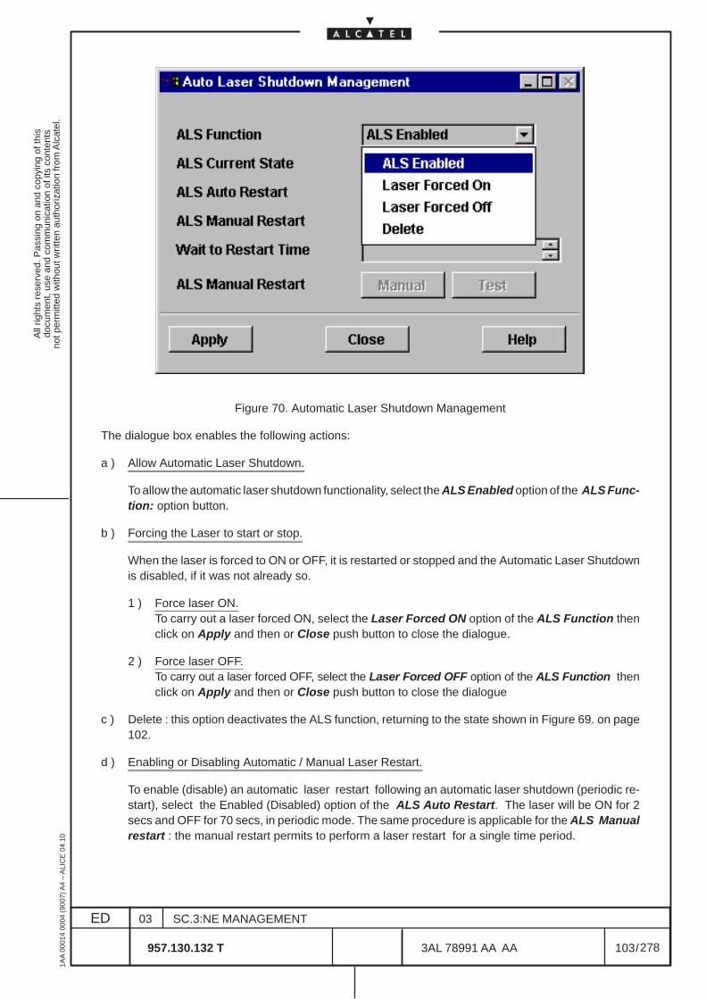
All
right
s re
serv
ed. P
assi
ng o
n an
d co
pyin
g of
this
docu
men
t, us
e an
d co
mm
unic
atio
n of
its
cont
ents
not p
erm
itted
with
out w
ritte
n au
thor
izat
ion
from
Alc
atel
.
ED
1AA
000
14 0
004
(900
7) A
4 –
ALI
CE
04.
10
103
03
957.130.132 T
SC.3:NE MANAGEMENT
/3AL 78991 AA AA
278
278
Figure 70. Automatic Laser Shutdown Management
The dialogue box enables the following actions:
a ) Allow Automatic Laser Shutdown.
To allow the automatic laser shutdown functionality, select the ALS Enabled option of the ALS Func-tion: option button.
b ) Forcing the Laser to start or stop.
When the laser is forced to ON or OFF, it is restarted or stopped and the Automatic Laser Shutdownis disabled, if it was not already so.
1 ) Force laser ON.To carry out a laser forced ON, select the Laser Forced ON option of the ALS Function thenclick on Apply and then or Close push button to close the dialogue.
2 ) Force laser OFF.To carry out a laser forced OFF, select the Laser Forced OFF option of the ALS Function thenclick on Apply and then or Close push button to close the dialogue
c ) Delete : this option deactivates the ALS function, returning to the state shown in Figure 69. on page102.
d ) Enabling or Disabling Automatic / Manual Laser Restart.
To enable (disable) an automatic laser restart following an automatic laser shutdown (periodic re-start), select the Enabled (Disabled) option of the ALS Auto Restart. The laser will be ON for 2secs and OFF for 70 secs, in periodic mode. The same procedure is applicable for the ALS Manualrestart : the manual restart permits to perform a laser restart for a single time period.
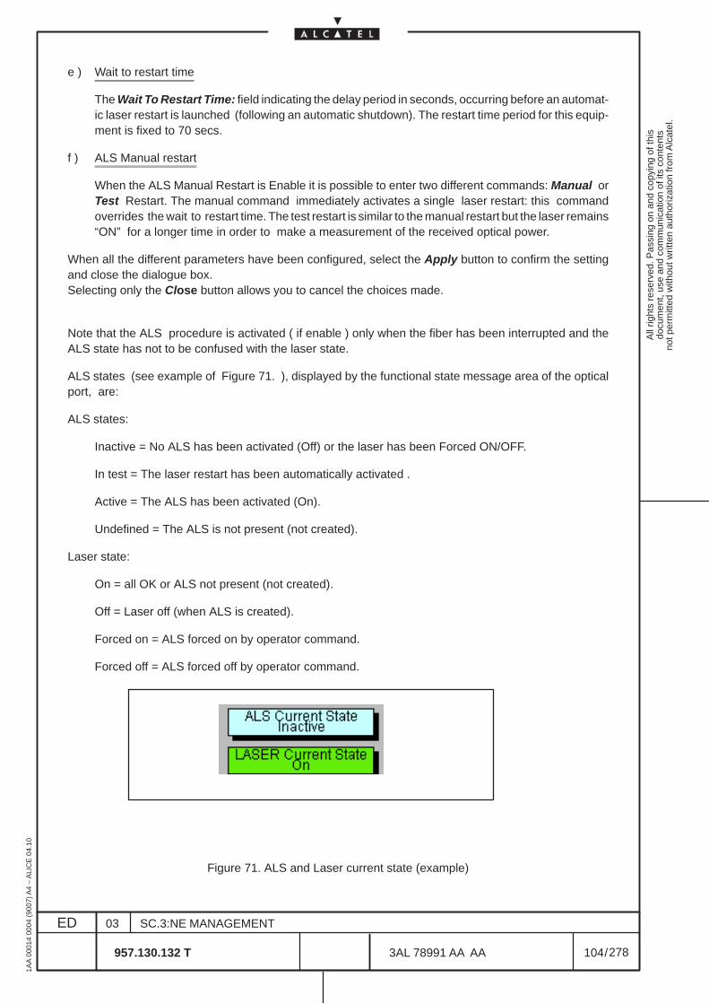
All
right
s re
serv
ed. P
assi
ng o
n an
d co
pyin
g of
this
docu
men
t, us
e an
d co
mm
unic
atio
n of
its
cont
ents
not p
erm
itted
with
out w
ritte
n au
thor
izat
ion
from
Alc
atel
.
ED
1AA
000
14 0
004
(900
7) A
4 –
ALI
CE
04.
10
104
03
957.130.132 T
SC.3:NE MANAGEMENT
/3AL 78991 AA AA
278
278
e ) Wait to restart time
The Wait To Restart Time: field indicating the delay period in seconds, occurring before an automat-ic laser restart is launched (following an automatic shutdown). The restart time period for this equip-ment is fixed to 70 secs.
f ) ALS Manual restart
When the ALS Manual Restart is Enable it is possible to enter two different commands: Manual orTest Restart. The manual command immediately activates a single laser restart: this commandoverrides the wait to restart time. The test restart is similar to the manual restart but the laser remains“ON” for a longer time in order to make a measurement of the received optical power.
When all the different parameters have been configured, select the Apply button to confirm the settingand close the dialogue box.Selecting only the Close button allows you to cancel the choices made.
Note that the ALS procedure is activated ( if enable ) only when the fiber has been interrupted and theALS state has not to be confused with the laser state.
ALS states (see example of Figure 71. ), displayed by the functional state message area of the opticalport, are:
ALS states:
Inactive = No ALS has been activated (Off) or the laser has been Forced ON/OFF.
In test = The laser restart has been automatically activated .
Active = The ALS has been activated (On).
Undefined = The ALS is not present (not created).
Laser state:
On = all OK or ALS not present (not created).
Off = Laser off (when ALS is created).
Forced on = ALS forced on by operator command.
Forced off = ALS forced off by operator command.
Figure 71. ALS and Laser current state (example)
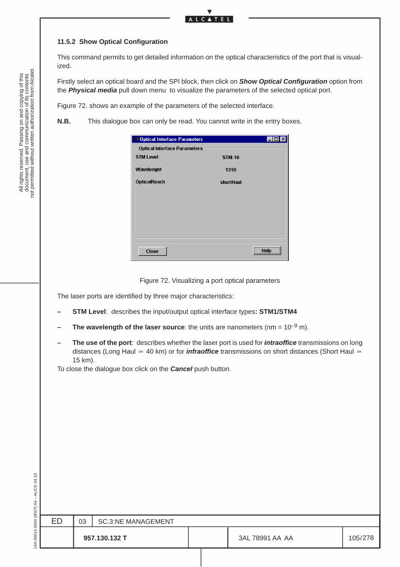
All
right
s re
serv
ed. P
assi
ng o
n an
d co
pyin
g of
this
docu
men
t, us
e an
d co
mm
unic
atio
n of
its
cont
ents
not p
erm
itted
with
out w
ritte
n au
thor
izat
ion
from
Alc
atel
.
ED
1AA
000
14 0
004
(900
7) A
4 –
ALI
CE
04.
10
105
03
957.130.132 T
SC.3:NE MANAGEMENT
/3AL 78991 AA AA
278
278
11.5.2 Show Optical Configuration
This command permits to get detailed information on the optical characteristics of the port that is visual-ized.
Firstly select an optical board and the SPI block, then click on Show Optical Configuration option fromthe Physical media pull down menu to visualize the parameters of the selected optical port.
Figure 72. shows an example of the parameters of the selected interface.
N.B. This dialogue box can only be read. You cannot write in the entry boxes.
Figure 72. Visualizing a port optical parameters
The laser ports are identified by three major characteristics:
– STM Level: describes the input/output optical interface types: STM1/STM4
– The wavelength of the laser source: the units are nanometers (nm = 10–9 m).
– The use of the port: describes whether the laser port is used for intraoffice transmissions on longdistances (Long Haul � 40 km) or for infraoffice transmissions on short distances (Short Haul �15 km).
To close the dialogue box click on the Cancel push button.
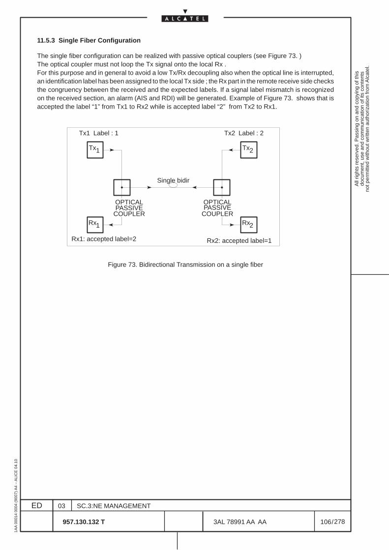
All
right
s re
serv
ed. P
assi
ng o
n an
d co
pyin
g of
this
docu
men
t, us
e an
d co
mm
unic
atio
n of
its
cont
ents
not p
erm
itted
with
out w
ritte
n au
thor
izat
ion
from
Alc
atel
.
ED
1AA
000
14 0
004
(900
7) A
4 –
ALI
CE
04.
10
106
03
957.130.132 T
SC.3:NE MANAGEMENT
/3AL 78991 AA AA
278
278
11.5.3 Single Fiber Configuration
The single fiber configuration can be realized with passive optical couplers (see Figure 73. )The optical coupler must not loop the Tx signal onto the local Rx .For this purpose and in general to avoid a low Tx/Rx decoupling also when the optical line is interrupted,an identification label has been assigned to the local Tx side ; the Rx part in the remote receive side checksthe congruency between the received and the expected labels. If a signal label mismatch is recognizedon the received section, an alarm (AIS and RDI) will be generated. Example of Figure 73. shows that isaccepted the label “1” from Tx1 to Rx2 while is accepted label “2” from Tx2 to Rx1.
Tx1 Tx2
Tx1 Label : 1 Tx2 Label : 2
Rx1 Rx2
OPTICALPASSIVE
COUPLER
OPTICALPASSIVE
COUPLER
Rx1: accepted label=2 Rx2: accepted label=1
Single bidir
Figure 73. Bidirectional Transmission on a single fiber
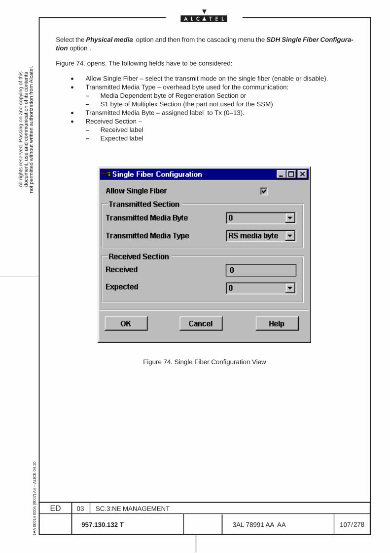
All
right
s re
serv
ed. P
assi
ng o
n an
d co
pyin
g of
this
docu
men
t, us
e an
d co
mm
unic
atio
n of
its
cont
ents
not p
erm
itted
with
out w
ritte
n au
thor
izat
ion
from
Alc
atel
.
ED
1AA
000
14 0
004
(900
7) A
4 –
ALI
CE
04.
10
107
03
957.130.132 T
SC.3:NE MANAGEMENT
/3AL 78991 AA AA
278
278
Select the Physical media option and then from the cascading menu the SDH Single Fiber Configura-tion option .
Figure 74. opens. The following fields have to be considered:
• Allow Single Fiber – select the transmit mode on the single fiber (enable or disable).• Transmitted Media Type – overhead byte used for the communication:
– Media Dependent byte of Regeneration Section or– S1 byte of Multiplex Section (the part not used for the SSM)
• Transmitted Media Byte – assigned label to Tx (0–13).• Received Section –
– Received label– Expected label
Figure 74. Single Fiber Configuration View
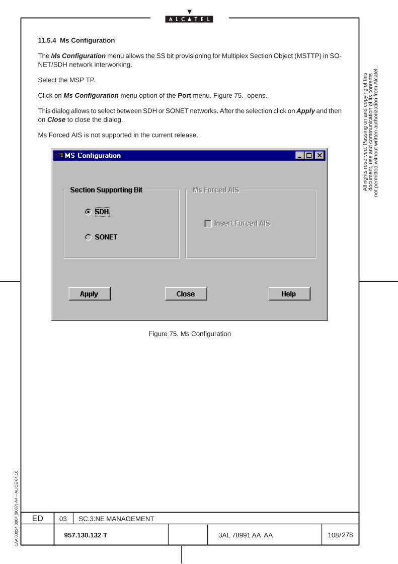
All
right
s re
serv
ed. P
assi
ng o
n an
d co
pyin
g of
this
docu
men
t, us
e an
d co
mm
unic
atio
n of
its
cont
ents
not p
erm
itted
with
out w
ritte
n au
thor
izat
ion
from
Alc
atel
.
ED
1AA
000
14 0
004
(900
7) A
4 –
ALI
CE
04.
10
108
03
957.130.132 T
SC.3:NE MANAGEMENT
/3AL 78991 AA AA
278
278
11.5.4 Ms Configuration
The Ms Configuration menu allows the SS bit provisioning for Multiplex Section Object (MSTTP) in SO-NET/SDH network interworking.
Select the MSP TP.
Click on Ms Configuration menu option of the Port menu. Figure 75. opens.
This dialog allows to select between SDH or SONET networks. After the selection click on Apply and thenon Close to close the dialog.
Ms Forced AIS is not supported in the current release.
Figure 75. Ms Configuration

All
right
s re
serv
ed. P
assi
ng o
n an
d co
pyin
g of
this
docu
men
t, us
e an
d co
mm
unic
atio
n of
its
cont
ents
not p
erm
itted
with
out w
ritte
n au
thor
izat
ion
from
Alc
atel
.
ED
1AA
000
14 0
004
(900
7) A
4 –
ALI
CE
04.
10
109
03
957.130.132 T
SC.3:NE MANAGEMENT
/3AL 78991 AA AA
278
278
11.5.5 PDH Line Length Configuration
To manage the Line Length configuration click on Line Length Configuration menu option of the Physi-cal Media menu. Figure 76. opens.
This dialog allows to configure the line length for a PDH PPI TP of a 45 Mbit/s port.
The OK button validate the configuration and close the dialog box.
The Cancel button removes the dialog
Figure 76. PDH Line Length Configuration View

All
right
s re
serv
ed. P
assi
ng o
n an
d co
pyin
g of
this
docu
men
t, us
e an
d co
mm
unic
atio
n of
its
cont
ents
not p
erm
itted
with
out w
ritte
n au
thor
izat
ion
from
Alc
atel
.
ED
1AA
000
14 0
004
(900
7) A
4 –
ALI
CE
04.
10
110
03
957.130.132 T
SC.3:NE MANAGEMENT
/3AL 78991 AA AA
278
278
11.6 Show Supporting Board
Select a TP.
Click on Show Supporting Board menu option of the Port menu to navigate to the board that supportsthe selected port view.
Figure 77. (example) opens.
Figure 77. Board View Example.
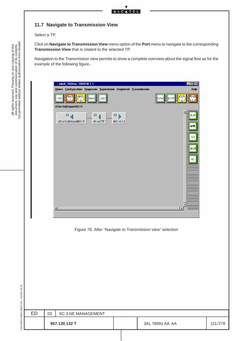
All
right
s re
serv
ed. P
assi
ng o
n an
d co
pyin
g of
this
docu
men
t, us
e an
d co
mm
unic
atio
n of
its
cont
ents
not p
erm
itted
with
out w
ritte
n au
thor
izat
ion
from
Alc
atel
.
ED
1AA
000
14 0
004
(900
7) A
4 –
ALI
CE
04.
10
111
03
957.130.132 T
SC.3:NE MANAGEMENT
/3AL 78991 AA AA
278
278
11.7 Navigate to Transmission View
Select a TP.
Click on Navigate to Transmission View menu option of the Port menu to navigate to the correspondingTransmission View that is related to the selected TP.
Navigation to the Transmission view permits to show a complete overview about the signal flow as for theexample of the following figure..
Figure 78. After “Navigate to Transmission view” selection

All
right
s re
serv
ed. P
assi
ng o
n an
d co
pyin
g of
this
docu
men
t, us
e an
d co
mm
unic
atio
n of
its
cont
ents
not p
erm
itted
with
out w
ritte
n au
thor
izat
ion
from
Alc
atel
.
ED
1AA
000
14 0
004
(900
7) A
4 –
ALI
CE
04.
10
112
03
957.130.132 T
SC.3:NE MANAGEMENT
/3AL 78991 AA AA
278
278
All
right
s re
serv
ed. P
assi
ng o
n an
d co
pyin
g of
this
docu
men
t, us
e an
d co
mm
unic
atio
n of
its
cont
ents
not p
erm
itted
with
out w
ritte
n au
thor
izat
ion
from
Alc
atel
.
ED
1AA
000
14 0
004
(900
7) A
4 –
ALI
CE
04.
10
113
03
957.130.132 T
SC.3:NE MANAGEMENT
/3AL 78991 AA AA
278
278
12 EQUIPMENT PROTECTION MANAGEMENT
12.1 Introduction
It is unthinkable to launch a telecommunications system, handling millions of communications, without thepossibility of replacing equipment in a real time way, consequent to equipment failure. Everything mustbe done so that the communications can continue smoothly and so that the equipment failure remainstransparent to the users. Protection management deals with this aspect of the EML–USM.
The protection is performed by switching the board supporting the protected service when this board failsto a protecting board capable of supporting the same service. This protection is realized according to aprotection scheme.
An equipment protection scheme is composed of the following parameters which can be configured:
• Group type: 1+1 or 1+nthe group type specifies if one or more unreliable resources for protection can be assigned toone or more reliables resources. 1+1 group type means that a working element is protected byone protecting unit. 1+n group type means that n working elements are protected by only oneprotecting unit.
• Protection priority:A priority can be assigned to protected units in 1+n protection schemes. This priority can be be1, 2, ... or n, 1 being the highest priority.
• Configuration type: revertive or non revertiveIn revertive mode, a protected service will be switched back to its protected element when it hasrecovered from its failure.In non revertive mode, the switch to the protecting element is maintained even after a recoveryfrom failure.
• Protection wait to restore time:Used when revertive mode is active, the protection wait to restore time prevents severalprotection switches due to an intermittent failure. A protected element must be fault free duringthis fixed period of time before a protected service is switched back to it.
Board duplication remains the easiest way to ensure equipment protection in a system.The actions that can be undertaken are of the following type:
– Consult and modify an Equipment Protection Scheme (EPS),– Force Switch EPS,
In Board view, the board whose contents is represented is considered as implicitly selected.
EPS protection states are displayed by the functional state message area of the boards involved in anequipment protection scheme.

All
right
s re
serv
ed. P
assi
ng o
n an
d co
pyin
g of
this
docu
men
t, us
e an
d co
mm
unic
atio
n of
its
cont
ents
not p
erm
itted
with
out w
ritte
n au
thor
izat
ion
from
Alc
atel
.
ED
1AA
000
14 0
004
(900
7) A
4 –
ALI
CE
04.
10
114
03
957.130.132 T
SC.3:NE MANAGEMENT
/3AL 78991 AA AA
278
278
12.2 Management: consulting and modifying EPS
In order to consult EPS, perform the following operations:
The “Port view” is reached selecting the Equipment option in the View pull down menu, then doubleclicking on the presented rack to present the subrack view, as described at chapter 9.1 on page 77.
– Select the Equipment option in the View pull down menu.– Double click on the presented rack to present the subrack view.– Select the EPS pull down menu. Then select the Management... option as show in the following
figure.
Figure 79. Consulting EPS
The following dialogue box is opened.
r01sr1/board#40
r01sr1/board#23
r01sr1/board#32
r01sr1/board#27
Figure 80. EPS Management dialogue box
All
right
s re
serv
ed. P
assi
ng o
n an
d co
pyin
g of
this
docu
men
t, us
e an
d co
mm
unic
atio
n of
its
cont
ents
not p
erm
itted
with
out w
ritte
n au
thor
izat
ion
from
Alc
atel
.
ED
1AA
000
14 0
004
(900
7) A
4 –
ALI
CE
04.
10
115
03
957.130.132 T
SC.3:NE MANAGEMENT
/3AL 78991 AA AA
278
278
The EPS Management dialogue box shows the current NE protection schemes in the left side. Thelist gives for each protecting board the protected board(s).
The available protection schemes are coherent with the NE type and release.
The right side of the dialogue box allows to modify the EPS configuration.
The current release of this NE fix the following protection:
• N+1 (with N ≤ 6)“P63E1” protection
– board of slot MAIN (protected): P63E1, slots 24–27–30–33–36–39
– board of slot SPARE (protecting): P63E1, slot 32
• N+1 (with N ≤ 15) “P3E3/T3” protection
– board of slot MAIN (protected): P3E3/T3, from slot 25 to 39
– board of slot SPARE (protecting): P3E3/T3, from slot 24 to 38
• N+1 (with N ≤ 15) “P4ES1N” protection
– board of slot MAIN (protected): P4ES1N, from slot 25 to 39
– board of slot SPARE (protecting): P4ES1N, from slot 24 to 38
N.B. For P3E3/T3 and P4ES1N more than one protection group N+1 revertive can be created,depending on the equipment configuration.The spare board position can be assigned in a flexible way .The only constraint are thefollowing:
• the access card corresponding to the protecting board must be an HPROT card• the HPROT card has to be plugged at the left side of the access card group• the main/spare boards have to be adjacent.• the protecting board has to be plugged at the left side of the protected group of boards• the protecting/protected group of ports have to be of the same type
• 1+1 “MATRIX” protection
– board of slot 23, MATRIX main (protected)
– board of slot 40, MATRIX spare (protecting)
N.B. for each type of failure on the MATRIX main board ( CRU, Shelf Controller) a switch isperformed to the spare boards.
The MATRIX protection is automatically presented in the left side of the dialog box whenthe SPARE MATRIX is created in the Set option of the Equipment menu. It is not createdwith the EPS menu described in this chapter.
This right side is divided into two parts.The upper part provides a message field with the name of the Protecting board and a choose button todisplay the list of boards available.The lower part provides a list to display the Protected boards currently in the displayed scheme.A choose button is provided to display the list of boards which could be added as protected.A delete button enables user to remove a protected board from a scheme.
All
right
s re
serv
ed. P
assi
ng o
n an
d co
pyin
g of
this
docu
men
t, us
e an
d co
mm
unic
atio
n of
its
cont
ents
not p
erm
itted
with
out w
ritte
n au
thor
izat
ion
from
Alc
atel
.
ED
1AA
000
14 0
004
(900
7) A
4 –
ALI
CE
04.
10
116
03
957.130.132 T
SC.3:NE MANAGEMENT
/3AL 78991 AA AA
278
278
a ) Scheme displaying
To display a specific scheme, user selects an item on the left list.This operation fills the protecting element text field and the protected list with the board user name. If userclicks where there is no item displayed, the right part is displayed empty.The Cancel push button closes the dialog box.
b ) Scheme creation
To create a new protection scheme,don’t click on item in the left list.In this way the right part is displayed empty and the Choose Protecting button is sensitive.Press this button to displays a window to choose a board in the “Board Selection” list (see Figure 81. onpage 117). The board are listed opening the NE>rack>subrack levels.
After that operation, Choose Protecting button becomes insensitive and Choose Protected becomessensitive (see Figure 82. on page 117)The user can add, always using the same “Board Selection” list dialogue box presented, as manyprotected boards as wanted (max.15 in this NE, N+1).
When the right part of window is correctly filled, the OK button close the dialog box and create the scheme(the new list is update re–opening the EPS Management dialogue box).The Cancel push button cancels the creation and closes the dialog box.
c ) Scheme deletion
To delete an existing protection scheme, the user selects a scheme in the left list. Using the Delete button,user could delete the scheme.
d ) Scheme modification
To modify an existing protection scheme by adding or removing protection units, the user selects a schemein the left list. Using Choose button for protected elements, user could add protected boards.By selecting a protected board and using the Delete Protected button, user could remove protectedelements from scheme. When the right part of window is correctly filled, the OK button close the dialogbox and modify the scheme.The Cancel push button cancels the creation and closes the dialog box.
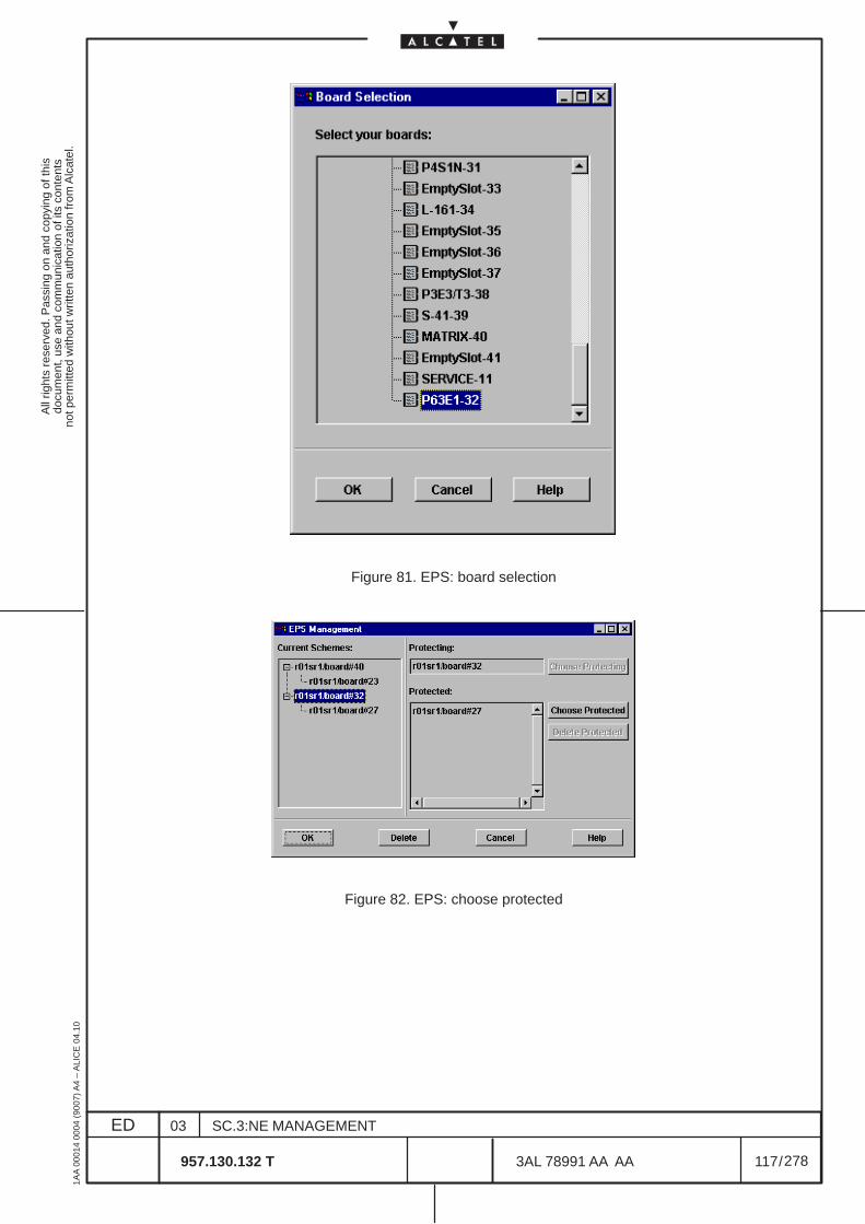
All
right
s re
serv
ed. P
assi
ng o
n an
d co
pyin
g of
this
docu
men
t, us
e an
d co
mm
unic
atio
n of
its
cont
ents
not p
erm
itted
with
out w
ritte
n au
thor
izat
ion
from
Alc
atel
.
ED
1AA
000
14 0
004
(900
7) A
4 –
ALI
CE
04.
10
117
03
957.130.132 T
SC.3:NE MANAGEMENT
/3AL 78991 AA AA
278
278
Figure 81. EPS: board selection
Figure 82. EPS: choose protected
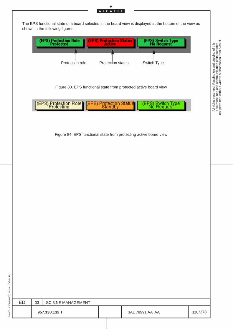
All
right
s re
serv
ed. P
assi
ng o
n an
d co
pyin
g of
this
docu
men
t, us
e an
d co
mm
unic
atio
n of
its
cont
ents
not p
erm
itted
with
out w
ritte
n au
thor
izat
ion
from
Alc
atel
.
ED
1AA
000
14 0
004
(900
7) A
4 –
ALI
CE
04.
10
118
03
957.130.132 T
SC.3:NE MANAGEMENT
/3AL 78991 AA AA
278
278
The EPS functional state of a board selected in the board view is displayed at the bottom of the view asshown in the following figures.
Protection role Protection status Switch Type
Figure 83. EPS functional state from protected active board view
Figure 84. EPS functional state from protecting active board view
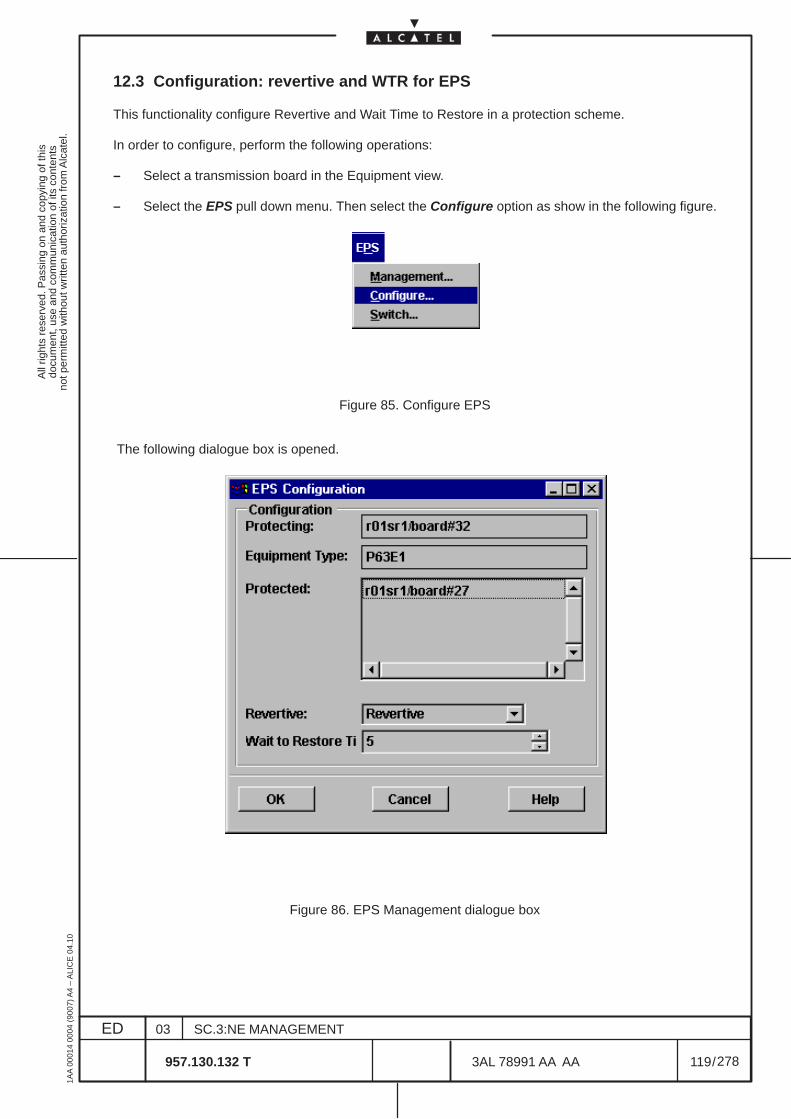
All
right
s re
serv
ed. P
assi
ng o
n an
d co
pyin
g of
this
docu
men
t, us
e an
d co
mm
unic
atio
n of
its
cont
ents
not p
erm
itted
with
out w
ritte
n au
thor
izat
ion
from
Alc
atel
.
ED
1AA
000
14 0
004
(900
7) A
4 –
ALI
CE
04.
10
119
03
957.130.132 T
SC.3:NE MANAGEMENT
/3AL 78991 AA AA
278
278
12.3 Configuration: revertive and WTR for EPS
This functionality configure Revertive and Wait Time to Restore in a protection scheme.
In order to configure, perform the following operations:
– Select a transmission board in the Equipment view.
– Select the EPS pull down menu. Then select the Configure option as show in the following figure.
Figure 85. Configure EPS
The following dialogue box is opened.
Figure 86. EPS Management dialogue box

All
right
s re
serv
ed. P
assi
ng o
n an
d co
pyin
g of
this
docu
men
t, us
e an
d co
mm
unic
atio
n of
its
cont
ents
not p
erm
itted
with
out w
ritte
n au
thor
izat
ion
from
Alc
atel
.
ED
1AA
000
14 0
004
(900
7) A
4 –
ALI
CE
04.
10
120
03
957.130.132 T
SC.3:NE MANAGEMENT
/3AL 78991 AA AA
278
278
The dialog box provides configuration for elements such as :
– the name of the protecting element as a label– the board type of the protecting element as a label– a list displaying the protected elements owned by the scheme– the revertive Mode flag as an option menu. The available values are revertive and non revertive– the wait time to restore time value (steps of 30 seconds, from 60 to 600). Only for N+1 EPS.
For this NE:
• 1+1 MATRIX is Not Revertive only
• N+1 63 x 2 Mbit/s (P63E1) protection is Revertive
• N+1 3x34/45 Mbit/s (P3E3/T3) protection is Revertive
• N+1 4x STM–1 ELECTRICAL port (P4ES1N) protection is Revertive
When the configuration of the equipment protection scheme is completed confirm closing the dialog boxby clicking on the OK push button. The Cancel push button cancels the configuration and closes the dialogbox.
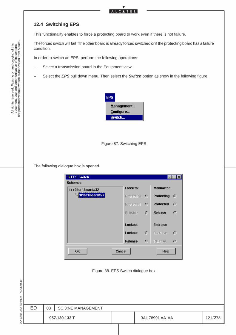
All
right
s re
serv
ed. P
assi
ng o
n an
d co
pyin
g of
this
docu
men
t, us
e an
d co
mm
unic
atio
n of
its
cont
ents
not p
erm
itted
with
out w
ritte
n au
thor
izat
ion
from
Alc
atel
.
ED
1AA
000
14 0
004
(900
7) A
4 –
ALI
CE
04.
10
121
03
957.130.132 T
SC.3:NE MANAGEMENT
/3AL 78991 AA AA
278
278
12.4 Switching EPS
This functionality enables to force a protecting board to work even if there is not failure.
The forced switch will fail if the other board is already forced switched or if the protecting board has a failurecondition.
In order to switch an EPS, perform the following operations:
– Select a transmission board in the Equipment view.
– Select the EPS pull down menu. Then select the Switch option as show in the following figure.
Figure 87. Switching EPS
The following dialogue box is opened.
Figure 88. EPS Switch dialogue box

All
right
s re
serv
ed. P
assi
ng o
n an
d co
pyin
g of
this
docu
men
t, us
e an
d co
mm
unic
atio
n of
its
cont
ents
not p
erm
itted
with
out w
ritte
n au
thor
izat
ion
from
Alc
atel
.
ED
1AA
000
14 0
004
(900
7) A
4 –
ALI
CE
04.
10
122
03
957.130.132 T
SC.3:NE MANAGEMENT
/3AL 78991 AA AA
278
278
This dialogue box displays in its left part the EPS of the selected board.
From this dialogue box the operator can configure, in the current release, only the Lockout options, byclicking on the relevant radio button.
The Manual to command perform the “manual” switch, active only if the other board is not alarmed.
Clicking on the OK push button will initiate the switch and close the dialogue box. The Cancel push buttoncancels the operation and closes the dialogue box.
All
right
s re
serv
ed. P
assi
ng o
n an
d co
pyin
g of
this
docu
men
t, us
e an
d co
mm
unic
atio
n of
its
cont
ents
not p
erm
itted
with
out w
ritte
n au
thor
izat
ion
from
Alc
atel
.
ED
1AA
000
14 0
004
(900
7) A
4 –
ALI
CE
04.
10
123
03
957.130.132 T
SC.3:NE MANAGEMENT
/3AL 78991 AA AA
278
278
13 MULTIPLEX SECTION PROTECTION MANAGEMENT
13.1 Architecture types
The Multiplex Section Protection is the connection between two NEs protected by a cable and portduplication. At the source the signal is duplicated and sent to the sink via two independent cables. Whenoccurs a multiplex section failure, the system switches to the other cable and port.
The MS Linear Trail Protection can be applied to any NE where it is possible to configure a linear APS(single ended/dual ended) line protection. For this NE is applicable the APS 1+1 Proprietary, the APS1+1 Standard and the APS 1 :1 Standard dual ended.
The APS 1 +1 (not revertive) feature permits a 1+1 protection in a linear link, where a path signal isprotected by another dedicated path carrying the same signal. The protection can be set both in single(unidirectional) and in dual (bidirectional) ended mode.In single ended mode (unidirectional) the protection is accomplished by switching only the signal affectedby the failure.In dual ended mode (bidirectional) the protection is accomplished by switching both the affected and theunaffected signals.
Architecture 1+1 StandardDescribed in ITU–T Rec. G783/G841. The refence switching criteria are SF and SD. It provides ak1/k2 communication protocol thus this protection can be single or dual ended.
Architecture 1+1 Proprietary (not used )The refence switching criteria are SF and SD. No k1/k2 communication protocol is provided thusthis protection can be only single ended.
Architecture 1+1 Optimized (not used )
Architecture 1 : 1 Standard (not used )Described in ITU–T Rec. G783/G841 as architecture 1 : n ( with n=1 ). The refence switching criteriaare SF and SD. It provides revertive mode managed by k1/k2 protocol and thus this protection canbe single or dual ended. The spare interface can be used to transport “low priority traffic” .
The WTR time is used with revertive mode.
Signal Degrade (SD) software setting enables the MSP protection mechanisms when a SD is recognizedon the working port. The SD threshold reference value depend on the NE selected threshold on the MStermination point. This threshold value is configured as explained in the para.14.8 on page 153.

All
right
s re
serv
ed. P
assi
ng o
n an
d co
pyin
g of
this
docu
men
t, us
e an
d co
mm
unic
atio
n of
its
cont
ents
not p
erm
itted
with
out w
ritte
n au
thor
izat
ion
from
Alc
atel
.
ED
1AA
000
14 0
004
(900
7) A
4 –
ALI
CE
04.
10
124
03
957.130.132 T
SC.3:NE MANAGEMENT
/3AL 78991 AA AA
278
278
13.2 MSP Options Introduction
All the MSP options are available starting from the Port View following the step explained below:
– Select Equipment from the Views menu
– Double click on rack/subrack.
– Double click on the SDH optical board to configure to open the port icon
– Double click on the port icon to open the port view
– Select the MSP block in the port view and then choose the MSP options by clicking on Port –> MSPmenu; the possible choice are:
• MSP Create see para 13.3 on page 125.
• MSP Management see para 13.4 on page 127.
• MSP Commands see para 13.5 on page 131.
• MSP Delete see para 13.6 on page 133.
MSP Management and MSP Commands ca also be accessed from the Transmission –> MSP menu.
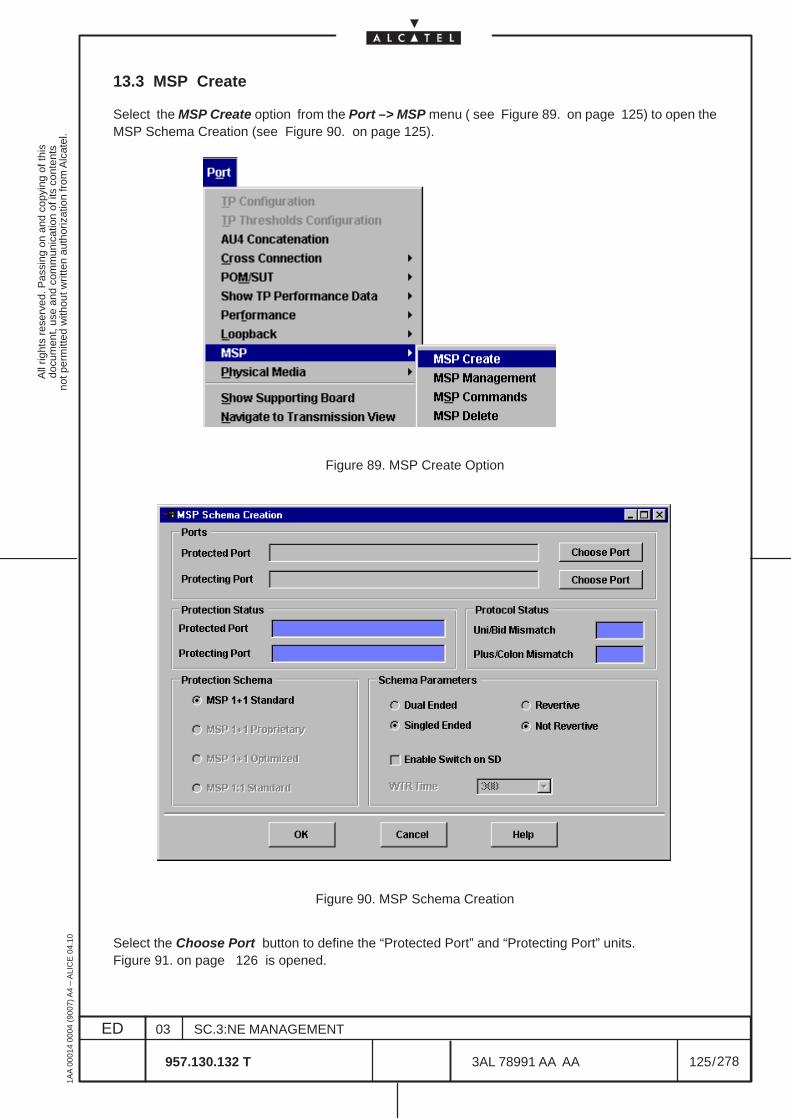
All
right
s re
serv
ed. P
assi
ng o
n an
d co
pyin
g of
this
docu
men
t, us
e an
d co
mm
unic
atio
n of
its
cont
ents
not p
erm
itted
with
out w
ritte
n au
thor
izat
ion
from
Alc
atel
.
ED
1AA
000
14 0
004
(900
7) A
4 –
ALI
CE
04.
10
125
03
957.130.132 T
SC.3:NE MANAGEMENT
/3AL 78991 AA AA
278
278
13.3 MSP Create
Select the MSP Create option from the Port –> MSP menu ( see Figure 89. on page 125) to open theMSP Schema Creation (see Figure 90. on page 125).
Figure 89. MSP Create Option
Figure 90. MSP Schema Creation
Select the Choose Port button to define the “Protected Port” and “Protecting Port” units.Figure 91. on page 126 is opened.
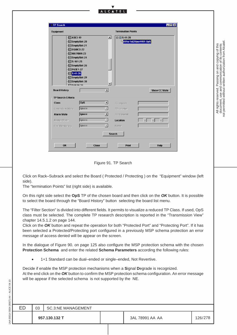
All
right
s re
serv
ed. P
assi
ng o
n an
d co
pyin
g of
this
docu
men
t, us
e an
d co
mm
unic
atio
n of
its
cont
ents
not p
erm
itted
with
out w
ritte
n au
thor
izat
ion
from
Alc
atel
.
ED
1AA
000
14 0
004
(900
7) A
4 –
ALI
CE
04.
10
126
03
957.130.132 T
SC.3:NE MANAGEMENT
/3AL 78991 AA AA
278
278
Figure 91. TP Search
Click on Rack–Subrack and select the Board ( Protected / Protecting ) on the “Equipment” window (leftside).The “termination Points” list (right side) is available.
On this right side select the OpS TP of the chosen board and then click on the OK button. It is possibleto select the board through the “Board History” button selecting the board list menu.
The “Filter Section” is divided into different fields. It permits to visualize a reduced TP Class. If used, OpSclass must be selected. The complete TP research description is reported in the “Transmission View”chapter 14.5.1.2 on page 144.Click on the OK button and repeat the operation for both “Protected Port” and “Protecting Port”. If it hasbeen selected a Protected/Protecting port configured in a previously MSP schema protection an errormessage of access denied will be appear on the screen.
In the dialogue of Figure 90. on page 125 also configure the MSP protection schema with the chosenProtection Schema and enter the related Schema Parameters according the following rules:
• 1+1 Standard can be dual–ended or single–ended, Not Revertive.
Decide if enable the MSP protection mechanisms when a Signal Degrade is recognized.At the end click on the OK button to confirm the MSP protection schema configuration. An error messagewill be appear if the selected schema is not supported by the NE.
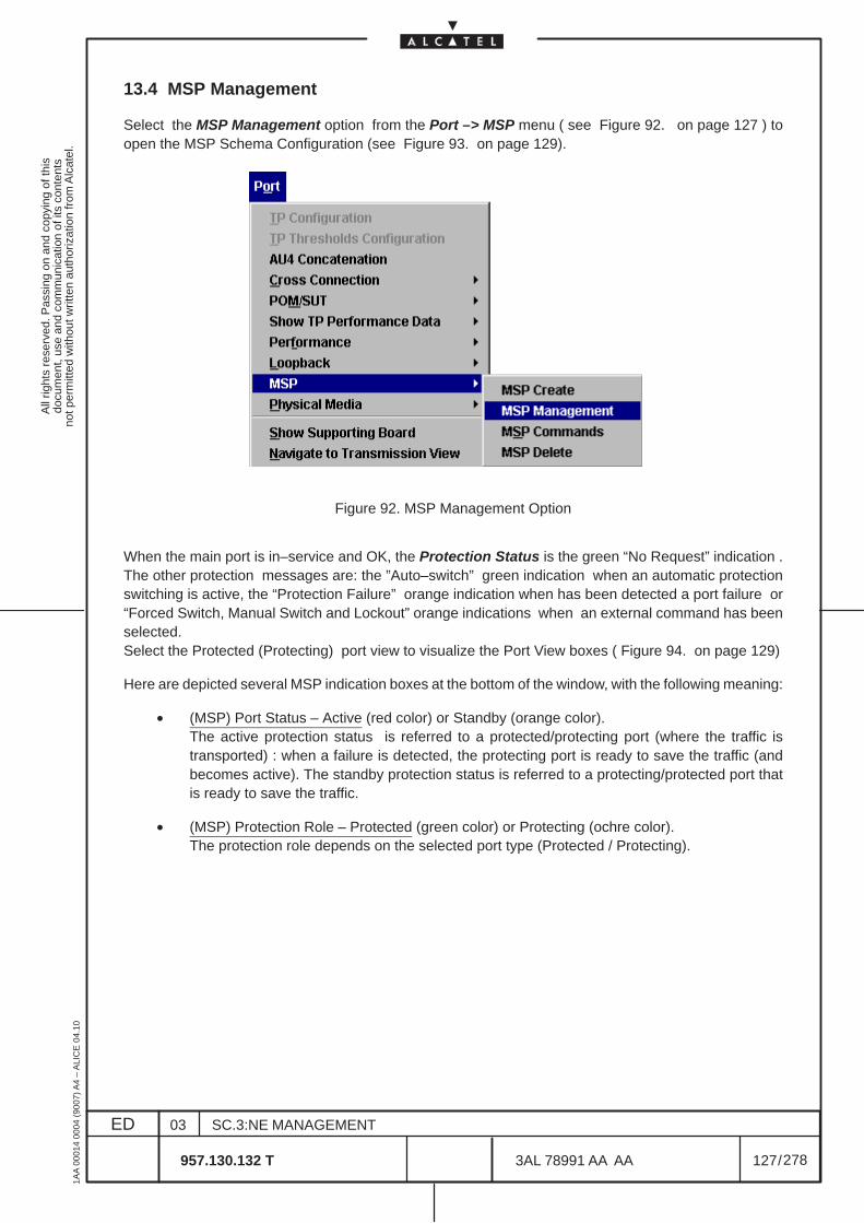
All
right
s re
serv
ed. P
assi
ng o
n an
d co
pyin
g of
this
docu
men
t, us
e an
d co
mm
unic
atio
n of
its
cont
ents
not p
erm
itted
with
out w
ritte
n au
thor
izat
ion
from
Alc
atel
.
ED
1AA
000
14 0
004
(900
7) A
4 –
ALI
CE
04.
10
127
03
957.130.132 T
SC.3:NE MANAGEMENT
/3AL 78991 AA AA
278
278
13.4 MSP Management
Select the MSP Management option from the Port –> MSP menu ( see Figure 92. on page 127 ) toopen the MSP Schema Configuration (see Figure 93. on page 129).
Figure 92. MSP Management Option
When the main port is in–service and OK, the Protection Status is the green “No Request” indication .The other protection messages are: the ”Auto–switch” green indication when an automatic protectionswitching is active, the “Protection Failure” orange indication when has been detected a port failure or“Forced Switch, Manual Switch and Lockout” orange indications when an external command has beenselected.Select the Protected (Protecting) port view to visualize the Port View boxes ( Figure 94. on page 129)
Here are depicted several MSP indication boxes at the bottom of the window, with the following meaning:
• (MSP) Port Status – Active (red color) or Standby (orange color).The active protection status is referred to a protected/protecting port (where the traffic istransported) : when a failure is detected, the protecting port is ready to save the traffic (andbecomes active). The standby protection status is referred to a protecting/protected port thatis ready to save the traffic.
• (MSP) Protection Role – Protected (green color) or Protecting (ochre color).The protection role depends on the selected port type (Protected / Protecting).
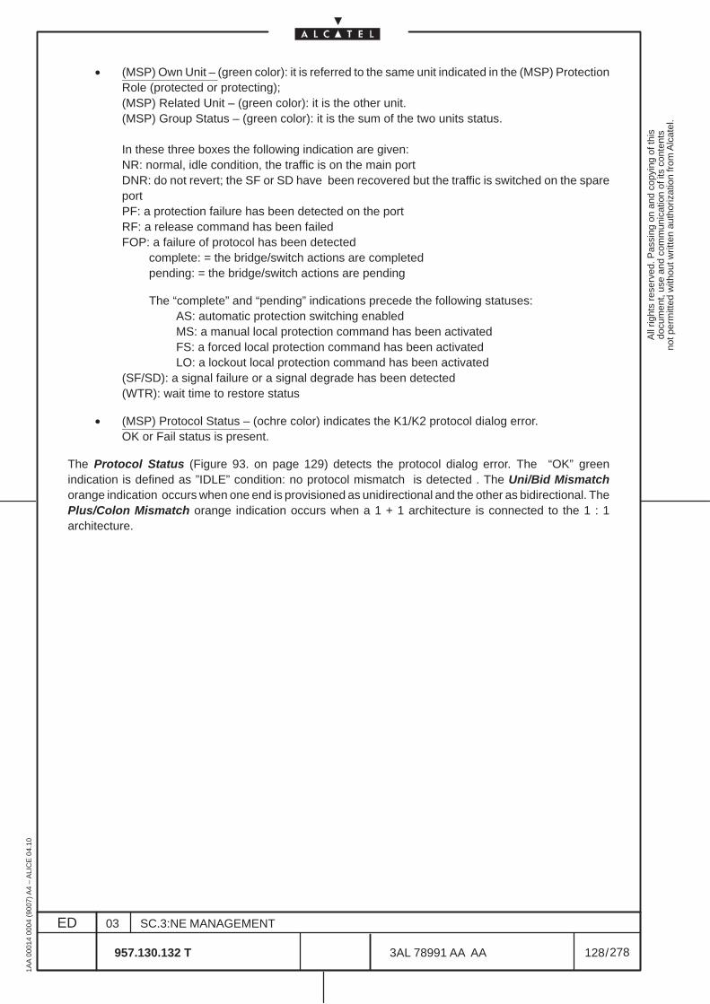
All
right
s re
serv
ed. P
assi
ng o
n an
d co
pyin
g of
this
docu
men
t, us
e an
d co
mm
unic
atio
n of
its
cont
ents
not p
erm
itted
with
out w
ritte
n au
thor
izat
ion
from
Alc
atel
.
ED
1AA
000
14 0
004
(900
7) A
4 –
ALI
CE
04.
10
128
03
957.130.132 T
SC.3:NE MANAGEMENT
/3AL 78991 AA AA
278
278
• (MSP) Own Unit – (green color): it is referred to the same unit indicated in the (MSP) ProtectionRole (protected or protecting);(MSP) Related Unit – (green color): it is the other unit.(MSP) Group Status – (green color): it is the sum of the two units status.
In these three boxes the following indication are given:NR: normal, idle condition, the traffic is on the main portDNR: do not revert; the SF or SD have been recovered but the traffic is switched on the spareportPF: a protection failure has been detected on the portRF: a release command has been failedFOP: a failure of protocol has been detected
complete: = the bridge/switch actions are completedpending: = the bridge/switch actions are pending
The “complete” and “pending” indications precede the following statuses:AS: automatic protection switching enabledMS: a manual local protection command has been activatedFS: a forced local protection command has been activatedLO: a lockout local protection command has been activated
(SF/SD): a signal failure or a signal degrade has been detected(WTR): wait time to restore status
• (MSP) Protocol Status – (ochre color) indicates the K1/K2 protocol dialog error.OK or Fail status is present.
The Protocol Status (Figure 93. on page 129) detects the protocol dialog error. The “OK” greenindication is defined as ”IDLE” condition: no protocol mismatch is detected . The Uni/Bid Mismatchorange indication occurs when one end is provisioned as unidirectional and the other as bidirectional. ThePlus/Colon Mismatch orange indication occurs when a 1 + 1 architecture is connected to the 1 : 1architecture.
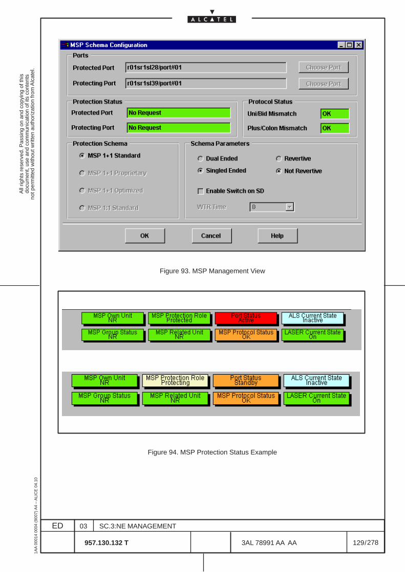
All
right
s re
serv
ed. P
assi
ng o
n an
d co
pyin
g of
this
docu
men
t, us
e an
d co
mm
unic
atio
n of
its
cont
ents
not p
erm
itted
with
out w
ritte
n au
thor
izat
ion
from
Alc
atel
.
ED
1AA
000
14 0
004
(900
7) A
4 –
ALI
CE
04.
10
129
03
957.130.132 T
SC.3:NE MANAGEMENT
/3AL 78991 AA AA
278
278
Figure 93. MSP Management View
Figure 94. MSP Protection Status Example
All
right
s re
serv
ed. P
assi
ng o
n an
d co
pyin
g of
this
docu
men
t, us
e an
d co
mm
unic
atio
n of
its
cont
ents
not p
erm
itted
with
out w
ritte
n au
thor
izat
ion
from
Alc
atel
.
ED
1AA
000
14 0
004
(900
7) A
4 –
ALI
CE
04.
10
130
03
957.130.132 T
SC.3:NE MANAGEMENT
/3AL 78991 AA AA
278
278
13.4.1 MSP modification
The same MSP Management option can be used to modify the schema parameters of an active MSPconfiguration.
Before changing a single ended (unidirectional) schema into a dual ended (bidirectional), all activeswitches must be cleared (manual switch, lockout,... ). If the operator wants to change the protectionschema architecture or the ports involved in the MSP schema, the current schema must be removed andre–created.
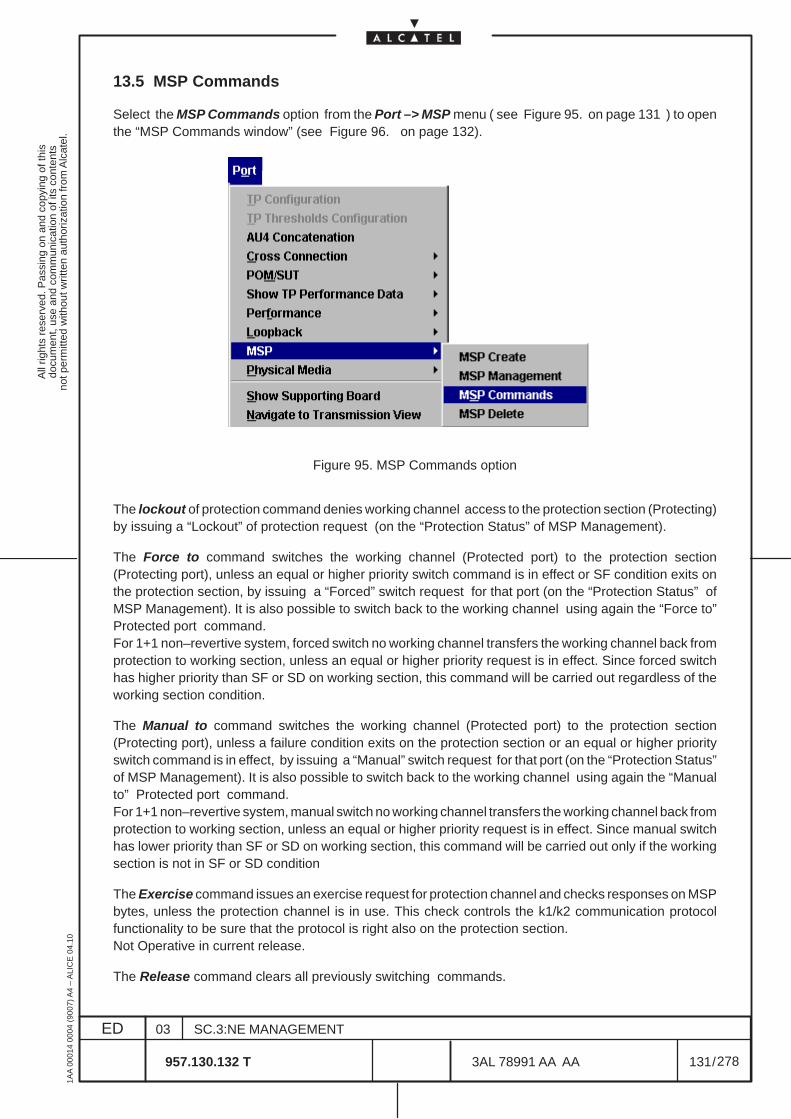
All
right
s re
serv
ed. P
assi
ng o
n an
d co
pyin
g of
this
docu
men
t, us
e an
d co
mm
unic
atio
n of
its
cont
ents
not p
erm
itted
with
out w
ritte
n au
thor
izat
ion
from
Alc
atel
.
ED
1AA
000
14 0
004
(900
7) A
4 –
ALI
CE
04.
10
131
03
957.130.132 T
SC.3:NE MANAGEMENT
/3AL 78991 AA AA
278
278
13.5 MSP Commands
Select the MSP Commands option from the Port –> MSP menu ( see Figure 95. on page 131 ) to openthe “MSP Commands window” (see Figure 96. on page 132).
Figure 95. MSP Commands option
The lockout of protection command denies working channel access to the protection section (Protecting)by issuing a “Lockout” of protection request (on the “Protection Status” of MSP Management).
The Force to command switches the working channel (Protected port) to the protection section(Protecting port), unless an equal or higher priority switch command is in effect or SF condition exits onthe protection section, by issuing a “Forced” switch request for that port (on the “Protection Status” ofMSP Management). It is also possible to switch back to the working channel using again the “Force to”Protected port command.For 1+1 non–revertive system, forced switch no working channel transfers the working channel back fromprotection to working section, unless an equal or higher priority request is in effect. Since forced switchhas higher priority than SF or SD on working section, this command will be carried out regardless of theworking section condition.
The Manual to command switches the working channel (Protected port) to the protection section(Protecting port), unless a failure condition exits on the protection section or an equal or higher priorityswitch command is in effect, by issuing a “Manual” switch request for that port (on the “Protection Status”of MSP Management). It is also possible to switch back to the working channel using again the “Manualto” Protected port command.For 1+1 non–revertive system, manual switch no working channel transfers the working channel back fromprotection to working section, unless an equal or higher priority request is in effect. Since manual switchhas lower priority than SF or SD on working section, this command will be carried out only if the workingsection is not in SF or SD condition
The Exercise command issues an exercise request for protection channel and checks responses on MSPbytes, unless the protection channel is in use. This check controls the k1/k2 communication protocolfunctionality to be sure that the protocol is right also on the protection section.Not Operative in current release.
The Release command clears all previously switching commands.
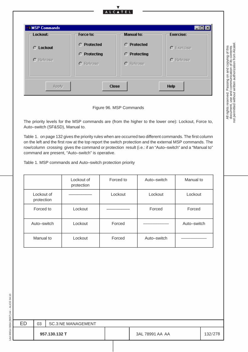
All
right
s re
serv
ed. P
assi
ng o
n an
d co
pyin
g of
this
docu
men
t, us
e an
d co
mm
unic
atio
n of
its
cont
ents
not p
erm
itted
with
out w
ritte
n au
thor
izat
ion
from
Alc
atel
.
ED
1AA
000
14 0
004
(900
7) A
4 –
ALI
CE
04.
10
132
03
957.130.132 T
SC.3:NE MANAGEMENT
/3AL 78991 AA AA
278
278
Figure 96. MSP Commands
The priority levels for the MSP commands are (from the higher to the lower one): Lockout, Force to,Auto–switch (SF&SD), Manual to.
Table 1. on page 132 gives the priority rules when are occurred two different commands. The first columnon the left and the first row at the top report the switch protection and the external MSP commands. Therow/column crossing gives the command or protection result (i.e.: if an “Auto–switch” and a “Manual to”command are present, “Auto–switch” is operative.
Table 1. MSP commands and Auto–switch protection priority
Lockout ofprotection
Forced to Auto–switch Manual to
Lockout ofprotection
–––––––––– Lockout Lockout Lockout
Forced to Lockout –––––––––– Forced Forced
Auto–switch
Lockout Forced ––––––––––– Auto–switch
Manual to Lockout Forced Auto–switch –––––––––––
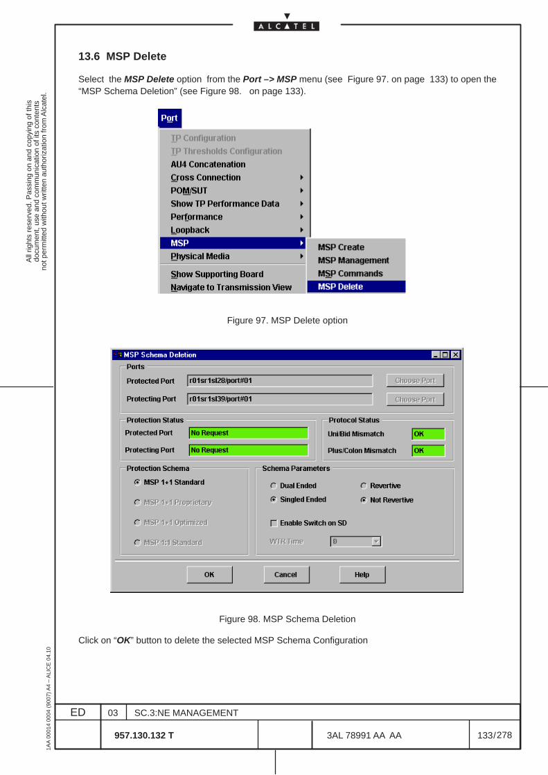
All
right
s re
serv
ed. P
assi
ng o
n an
d co
pyin
g of
this
docu
men
t, us
e an
d co
mm
unic
atio
n of
its
cont
ents
not p
erm
itted
with
out w
ritte
n au
thor
izat
ion
from
Alc
atel
.
ED
1AA
000
14 0
004
(900
7) A
4 –
ALI
CE
04.
10
133
03
957.130.132 T
SC.3:NE MANAGEMENT
/3AL 78991 AA AA
278
278
13.6 MSP Delete
Select the MSP Delete option from the Port –> MSP menu (see Figure 97. on page 133) to open the“MSP Schema Deletion” (see Figure 98. on page 133).
Figure 97. MSP Delete option
Figure 98. MSP Schema Deletion
Click on “OK” button to delete the selected MSP Schema Configuration

All
right
s re
serv
ed. P
assi
ng o
n an
d co
pyin
g of
this
docu
men
t, us
e an
d co
mm
unic
atio
n of
its
cont
ents
not p
erm
itted
with
out w
ritte
n au
thor
izat
ion
from
Alc
atel
.
ED
1AA
000
14 0
004
(900
7) A
4 –
ALI
CE
04.
10
134
03
957.130.132 T
SC.3:NE MANAGEMENT
/3AL 78991 AA AA
278
278
All
right
s re
serv
ed. P
assi
ng o
n an
d co
pyin
g of
this
docu
men
t, us
e an
d co
mm
unic
atio
n of
its
cont
ents
not p
erm
itted
with
out w
ritte
n au
thor
izat
ion
from
Alc
atel
.
ED
1AA
000
14 0
004
(900
7) A
4 –
ALI
CE
04.
10
135
03
957.130.132 T
SC.3:NE MANAGEMENT
/3AL 78991 AA AA
278
278
14 TRANSMISSION VIEW
14.1 Overview
This section describes the operations necessary for the consultation, modification and configuration ofTPs, providing a representation of the entire signal flow.
The generic Transmission View, described in this chapter, offers the possibility of displaying a single TPor a set of all kinds of TPs (or collected functionality which is represented by one/several TPs).
To display the termination points in the Transmission View, either select specific TPs from a TP searchdialog or access the view directly from another view, e.g. by navigating from the Port View.
The Transmission View provides the following features:
– Brief overview regarding transmission resources.
• An overview concerning all TPs belonging to a port can be called in by activating the functionto expand the selected TP. TP names are listed in an additional information area if the mousepointer is positioned over it. The following states are indicated:
– the alarm state is indicated by the alarm synthesis icon
– the cross-connection state is indicated by a cross
– whether a TP can be structured is indicated by a circle
• An overview concerning signal flow can be requested by a user action. The user can selecta TP and apply the action Show Cross-connected TPs. The result is that the objects relatedto the TP are displayed and lines indicate the connections. Expanding and hiding TPs that arerelated to the currently selected TP (e.g. show all TPs that are above the TU-12 CTP) enablesall related TPs to be added to the view, thus providing a representation of the entire signal flow.
– Display of single or multiple termination points.
• Search for and select a termination point in a TP search dialog and display it in the TransmissionView.
• Pop-up the Transmission View from the board view. All TPs/compound TPs associated with thephysical port are displayed (i.e. TPs down to AU-4).
– Provide the functionality to create/show cross-connections.
– Provide the functionality to create/show Multiplex Section Protection
– Provide the functionality to create/show Loopback commands.
– Provide the possibility of configuring a selected TP. This functionality is accessed by calling theconfiguration dialogs of the common Transmission/Port Views category.
– Provide the possibility of showing a detailed view of a TP with alarms, navigating to the Port view.
– Provide the possibility of showing and setting Performance Monitoring parameters and data.
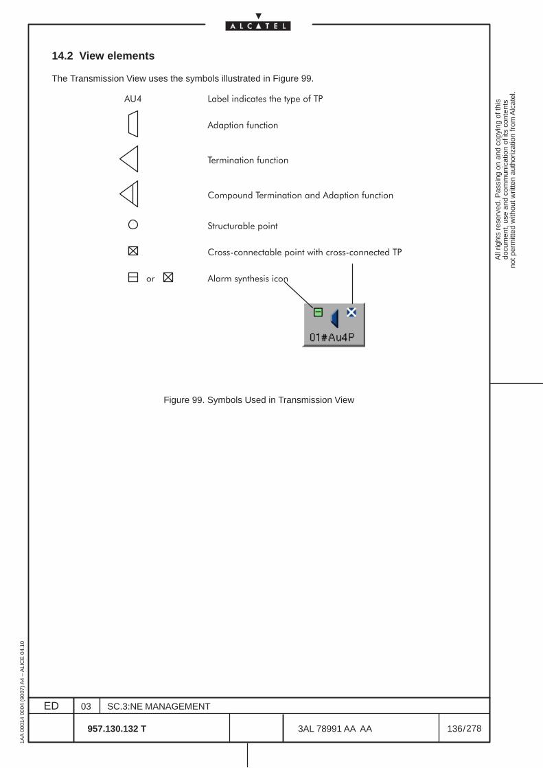
All
right
s re
serv
ed. P
assi
ng o
n an
d co
pyin
g of
this
docu
men
t, us
e an
d co
mm
unic
atio
n of
its
cont
ents
not p
erm
itted
with
out w
ritte
n au
thor
izat
ion
from
Alc
atel
.
ED
1AA
000
14 0
004
(900
7) A
4 –
ALI
CE
04.
10
136
03
957.130.132 T
SC.3:NE MANAGEMENT
/3AL 78991 AA AA
278
278
14.2 View elements
The Transmission View uses the symbols illustrated in Figure 99.
��������������� ������������
���������������
�������������������
��������������������������������������
�����������������
������������������������� ���������������
���
���������� ����������
Figure 99. Symbols Used in Transmission View
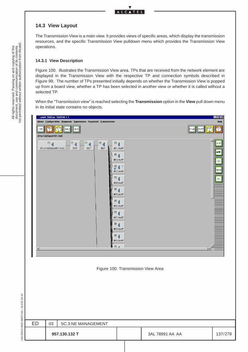
All
right
s re
serv
ed. P
assi
ng o
n an
d co
pyin
g of
this
docu
men
t, us
e an
d co
mm
unic
atio
n of
its
cont
ents
not p
erm
itted
with
out w
ritte
n au
thor
izat
ion
from
Alc
atel
.
ED
1AA
000
14 0
004
(900
7) A
4 –
ALI
CE
04.
10
137
03
957.130.132 T
SC.3:NE MANAGEMENT
/3AL 78991 AA AA
278
278
14.3 View Layout
The Transmission View is a main view. It provides views of specific areas, which display the transmissionresources, and the specific Transmission View pulldown menu which provides the Transmission Viewoperations.
14.3.1 View Description
Figure 100. illustrates the Transmission View area. TPs that are received from the network element aredisplayed in the Transmission View with the respective TP and connection symbols described inFigure 99. The number of TPs presented initially depends on whether the Transmission View is poppedup from a board view, whether a TP has been selected in another view or whether it is called without aselected TP.
When the “Transmission view” is reached selecting the Transmission option in the View pull down menuin its initial state contains no objects.
Figure 100. Transmission View Area
All
right
s re
serv
ed. P
assi
ng o
n an
d co
pyin
g of
this
docu
men
t, us
e an
d co
mm
unic
atio
n of
its
cont
ents
not p
erm
itted
with
out w
ritte
n au
thor
izat
ion
from
Alc
atel
.
ED
1AA
000
14 0
004
(900
7) A
4 –
ALI
CE
04.
10
138
03
957.130.132 T
SC.3:NE MANAGEMENT
/3AL 78991 AA AA
278
278
14.3.2 Number of TPs Displayed in Transmission View
It is possible both to expand a VC-4, thus displaying all underlying TPs, and to hide TPs which are of nointerest. The objects initially displayed depend on the situation/definition.
14.3.3 Naming TPs
The following rules are applied in order to identify the TPs displayed:
– the root node contains the full user label,
– all child nodes contain a short label indicating the position inside the tree.
14.3.4 Dynamic View Behavior
The following section describes the view states and provides a short description of events that affect theview.
14.3.4.1 Initial state of the view
In its initial state, the Transmission View contains no objects. Objects can be searched for and displayedusing the Add TP dialog.
14.3.4.2 Working state of the view
In its working state, the Transmission View already contains objects. If the operator searches for anddisplays a TP using the TP Search dialog, the view is first initialized again and then the TP is displayed.The same applies in the case of navigation from another view to the Transmission View – the TransmissionView is always initialized and the corresponding objects are then displayed in it.
14.3.4.3 Navigation to Transmission View from other views
If the Transmission View is popped up from the Port View, only the selected TP is displayed.
14.3.4.4 Alarm notification
Alarms concerning the TPs displayed are indicated graphically by the alarm synthesis icons of the TPobjects. The TP objects are updated accordingly.
14.3.4.5 Object deletion
All kinds of object deletion events related to TPs displayed are indicated by the TP objects. The graphicalobjects are removed accordingly from the Transmission View. Example: modification of the payloadstructure from 63 TU-12 to 3 TU-3.
All
right
s re
serv
ed. P
assi
ng o
n an
d co
pyin
g of
this
docu
men
t, us
e an
d co
mm
unic
atio
n of
its
cont
ents
not p
erm
itted
with
out w
ritte
n au
thor
izat
ion
from
Alc
atel
.
ED
1AA
000
14 0
004
(900
7) A
4 –
ALI
CE
04.
10
139
03
957.130.132 T
SC.3:NE MANAGEMENT
/3AL 78991 AA AA
278
278
14.4 Transmission view access and menu
The “Transmission view” can be reached selecting the Transmission option in the View pull down menu.In this case, in its initial state, the Transmission View contains no objects.
In the case of navigation from another view (example the “Port view”) to the Transmission View, theTransmission View is always initialized and the corresponding objects are then displayed in it (see forexample Figure 100. on page 137.
Selecting the “Transmission” option in the menu bar of Figure 100. on page 137. the complete pull downTransmission menu is presented (Figure 101. )
The following menu items are available:
– Add TP Select the TP to show on the Transmission view.It is described in the following paragraph.
– Expand Display TPs that are related to the selected TP.It is described in this chapter, see para 14.15.1 on page 169.
– Hide Hide TPs that are related to the selected TP or the selected TP.It is described in this chapter, see para 14.15.2 on page 170
– TP Configuration Set parameters for the Overhead on Synchronous TP’s.It is described in this chapter, see para 14.6 on page 148
– PDH TP Configuration Set parameters for the Plesiochronous TP’s to use it as a timingreference.It is described in this chapter, see para 14.7 on page 152
– TP Threshold Configuration Set B2 ExBER and Degraded Signal parameters.It is described in this paragraph, see para.14.8 on page 153.
– Alarm Persistency Time Helps to suppress oscillating alarms.It is described in this chapter, see para 14.9 on page 154
– Terminate TP Terminate a path on a AU-4 CTPIt is described in this chapter, see para 14.10 on page 155
– Disterminate TP Disterminate a path on a AU-4 CTPIt is described in this chapter, see para 14.10 on page 155
– Cross-Connection Manage the connection of the paths. See para. 15 on page 173
– POM/SUT Create, configure and delete POM/SUT TP’s.It is described in this chapter, see para 14.11 on page 156
– Performance Set and show Performance Monitoring parameters and data.See chapter 17 on page 231.
– Structure TPs Provides the possibility of structuring and destructuring selected TPIt is described in this chapter, see para 14.12 on page 161
– Loopback Manage the loopback commands, for commissioning ormaintenance purposes. See paragraph 14.13 on page 162.
– Physical Media Manage the physical TP setting. See para 14.14 on page 167.
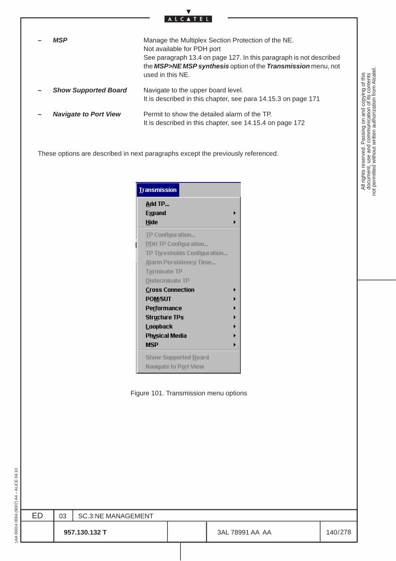
All
right
s re
serv
ed. P
assi
ng o
n an
d co
pyin
g of
this
docu
men
t, us
e an
d co
mm
unic
atio
n of
its
cont
ents
not p
erm
itted
with
out w
ritte
n au
thor
izat
ion
from
Alc
atel
.
ED
1AA
000
14 0
004
(900
7) A
4 –
ALI
CE
04.
10
140
03
957.130.132 T
SC.3:NE MANAGEMENT
/3AL 78991 AA AA
278
278
– MSP Manage the Multiplex Section Protection of the NE. Not available for PDH port
See paragraph 13.4 on page 127. In this paragraph is not describedthe MSP>NE MSP synthesis option of the Transmission menu, notused in this NE.
– Show Supported Board Navigate to the upper board level.It is described in this chapter, see para 14.15.3 on page 171
– Navigate to Port View Permit to show the detailed alarm of the TP.It is described in this chapter, see 14.15.4 on page 172
These options are described in next paragraphs except the previously referenced.
Figure 101. Transmission menu options
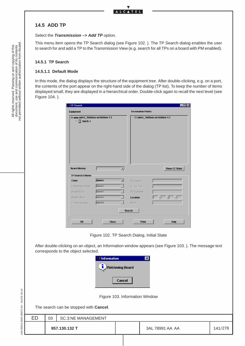
All
right
s re
serv
ed. P
assi
ng o
n an
d co
pyin
g of
this
docu
men
t, us
e an
d co
mm
unic
atio
n of
its
cont
ents
not p
erm
itted
with
out w
ritte
n au
thor
izat
ion
from
Alc
atel
.
ED
1AA
000
14 0
004
(900
7) A
4 –
ALI
CE
04.
10
141
03
957.130.132 T
SC.3:NE MANAGEMENT
/3AL 78991 AA AA
278
278
14.5 ADD TP
Select the Transmission –> Add TP option.
This menu item opens the TP Search dialog (see Figure 102. ). The TP Search dialog enables the userto search for and add a TP to the Transmission View (e.g. search for all TPs on a board with PM enabled).
14.5.1 TP Search
14.5.1.1 Default Mode
In this mode, the dialog displays the structure of the equipment tree. After double-clicking, e.g. on a port,the contents of the port appear on the right-hand side of the dialog (TP list). To keep the number of itemsdisplayed small, they are displayed in a hierarchical order. Double-click again to recall the next level (seeFigure 104. ).
Figure 102. TP Search Dialog, Initial State
After double-clicking on an object, an Information window appears (see Figure 103. ). The message textcorresponds to the object selected.
Figure 103. Information Window
The search can be stopped with Cancel.
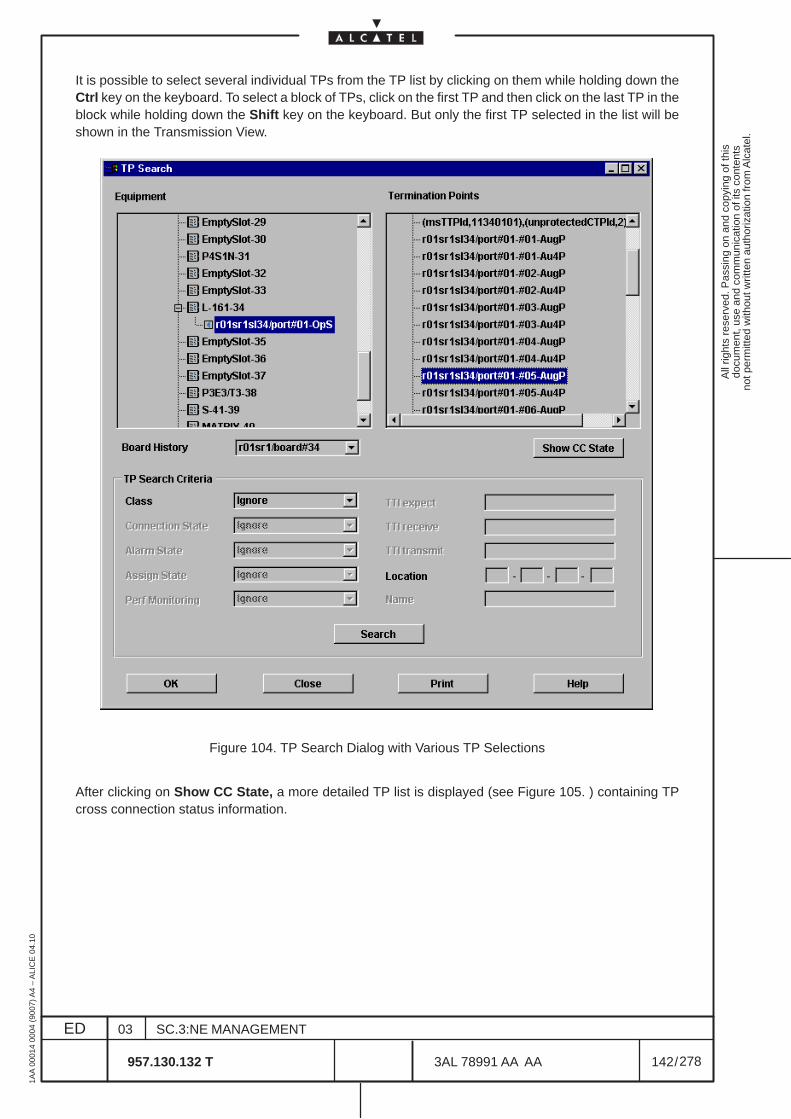
All
right
s re
serv
ed. P
assi
ng o
n an
d co
pyin
g of
this
docu
men
t, us
e an
d co
mm
unic
atio
n of
its
cont
ents
not p
erm
itted
with
out w
ritte
n au
thor
izat
ion
from
Alc
atel
.
ED
1AA
000
14 0
004
(900
7) A
4 –
ALI
CE
04.
10
142
03
957.130.132 T
SC.3:NE MANAGEMENT
/3AL 78991 AA AA
278
278
It is possible to select several individual TPs from the TP list by clicking on them while holding down theCtrl key on the keyboard. To select a block of TPs, click on the first TP and then click on the last TP in theblock while holding down the Shift key on the keyboard. But only the first TP selected in the list will beshown in the Transmission View.
Figure 104. TP Search Dialog with Various TP Selections
After clicking on Show CC State, a more detailed TP list is displayed (see Figure 105. ) containing TPcross connection status information.
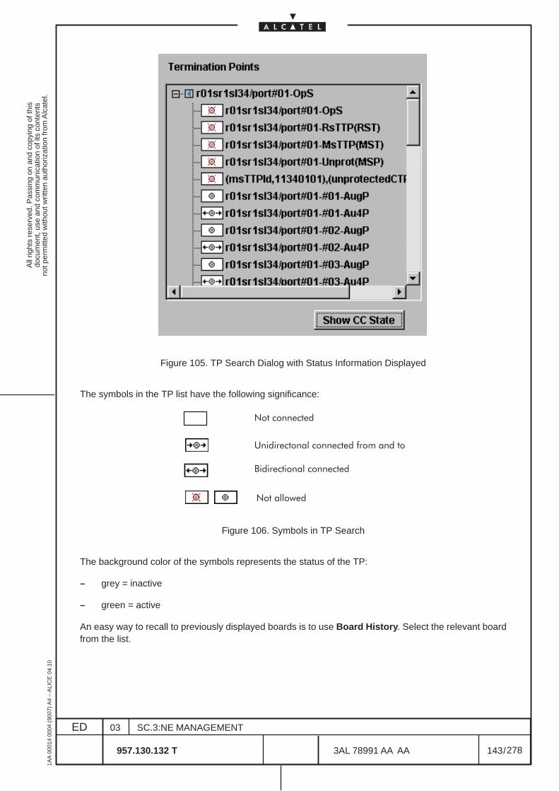
All
right
s re
serv
ed. P
assi
ng o
n an
d co
pyin
g of
this
docu
men
t, us
e an
d co
mm
unic
atio
n of
its
cont
ents
not p
erm
itted
with
out w
ritte
n au
thor
izat
ion
from
Alc
atel
.
ED
1AA
000
14 0
004
(900
7) A
4 –
ALI
CE
04.
10
143
03
957.130.132 T
SC.3:NE MANAGEMENT
/3AL 78991 AA AA
278
278
Figure 105. TP Search Dialog with Status Information Displayed
The symbols in the TP list have the following significance:
����������
������������������
�����������������������������
����������
Figure 106. Symbols in TP Search
The background color of the symbols represents the status of the TP:
– grey = inactive
– green = active
An easy way to recall to previously displayed boards is to use Board History. Select the relevant boardfrom the list.
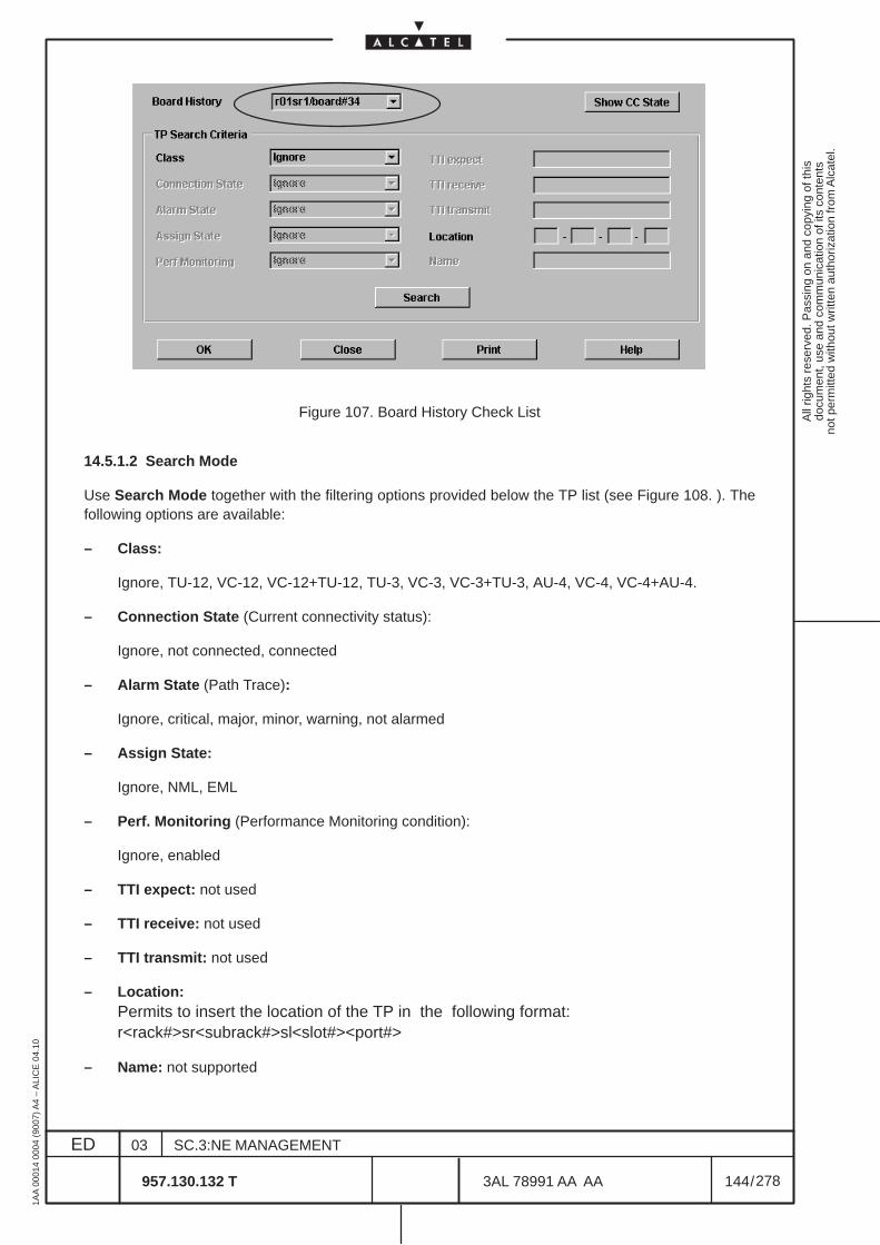
All
right
s re
serv
ed. P
assi
ng o
n an
d co
pyin
g of
this
docu
men
t, us
e an
d co
mm
unic
atio
n of
its
cont
ents
not p
erm
itted
with
out w
ritte
n au
thor
izat
ion
from
Alc
atel
.
ED
1AA
000
14 0
004
(900
7) A
4 –
ALI
CE
04.
10
144
03
957.130.132 T
SC.3:NE MANAGEMENT
/3AL 78991 AA AA
278
278
Figure 107. Board History Check List
14.5.1.2 Search Mode
Use Search Mode together with the filtering options provided below the TP list (see Figure 108. ). Thefollowing options are available:
– Class:
Ignore, TU-12, VC-12, VC-12+TU-12, TU-3, VC-3, VC-3+TU-3, AU-4, VC-4, VC-4+AU-4.
– Connection State (Current connectivity status):
Ignore, not connected, connected
– Alarm State (Path Trace):
Ignore, critical, major, minor, warning, not alarmed
– Assign State:
Ignore, NML, EML
– Perf. Monitoring (Performance Monitoring condition):
Ignore, enabled
– TTI expect: not used
– TTI receive: not used
– TTI transmit: not used
– Location:Permits to insert the location of the TP in the following format:r<rack#>sr<subrack#>sl<slot#><port#>
– Name: not supported
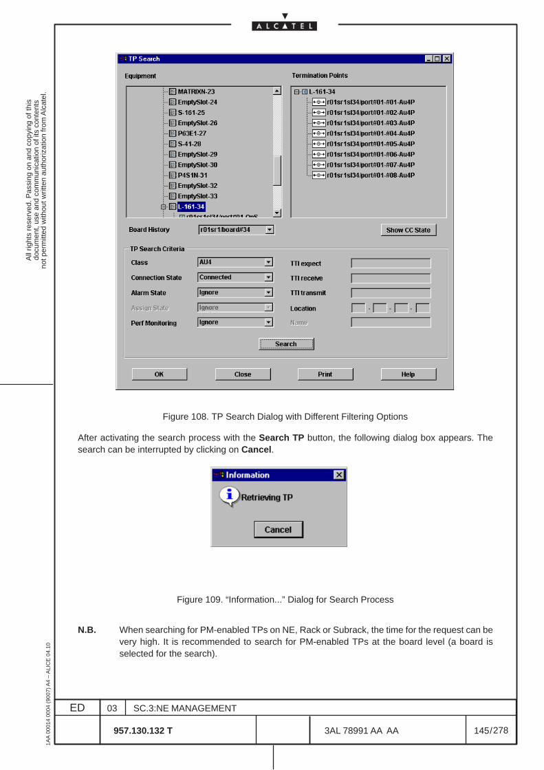
All
right
s re
serv
ed. P
assi
ng o
n an
d co
pyin
g of
this
docu
men
t, us
e an
d co
mm
unic
atio
n of
its
cont
ents
not p
erm
itted
with
out w
ritte
n au
thor
izat
ion
from
Alc
atel
.
ED
1AA
000
14 0
004
(900
7) A
4 –
ALI
CE
04.
10
145
03
957.130.132 T
SC.3:NE MANAGEMENT
/3AL 78991 AA AA
278
278
Figure 108. TP Search Dialog with Different Filtering Options
After activating the search process with the Search TP button, the following dialog box appears. Thesearch can be interrupted by clicking on Cancel.
Figure 109. “Information...” Dialog for Search Process
N.B. When searching for PM-enabled TPs on NE, Rack or Subrack, the time for the request can bevery high. It is recommended to search for PM-enabled TPs at the board level (a board isselected for the search).
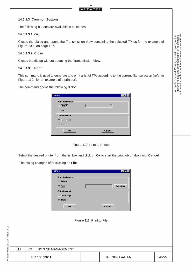
All
right
s re
serv
ed. P
assi
ng o
n an
d co
pyin
g of
this
docu
men
t, us
e an
d co
mm
unic
atio
n of
its
cont
ents
not p
erm
itted
with
out w
ritte
n au
thor
izat
ion
from
Alc
atel
.
ED
1AA
000
14 0
004
(900
7) A
4 –
ALI
CE
04.
10
146
03
957.130.132 T
SC.3:NE MANAGEMENT
/3AL 78991 AA AA
278
278
14.5.1.3 Common Buttons
The following buttons are available in all modes:
14.5.1.3.1 Ok
Closes the dialog and opens the Transmission View containing the selected TP, as for the example ofFigure 100. on page 137.
14.5.1.3.2 Close
Closes the dialog without updating the Transmission View.
14.5.1.3.3 Print
This command is used to generate and print a list of TPs according to the current filter selection (refer toFigure 112. for an example of a printout).
The command opens the following dialog:
Figure 110. Print to Printer
Select the desired printer from the list box and click on Ok to start the print job or abort with Cancel.
The dialog changes after clicking on File:
Figure 111. Print to File
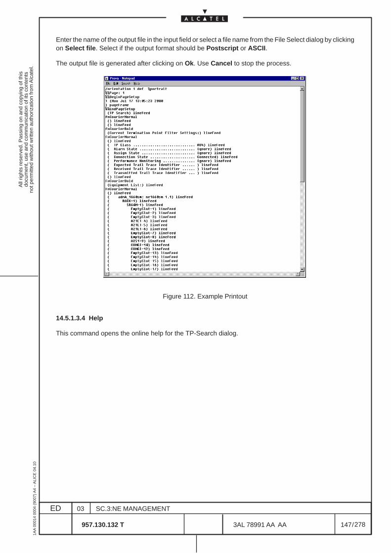
All
right
s re
serv
ed. P
assi
ng o
n an
d co
pyin
g of
this
docu
men
t, us
e an
d co
mm
unic
atio
n of
its
cont
ents
not p
erm
itted
with
out w
ritte
n au
thor
izat
ion
from
Alc
atel
.
ED
1AA
000
14 0
004
(900
7) A
4 –
ALI
CE
04.
10
147
03
957.130.132 T
SC.3:NE MANAGEMENT
/3AL 78991 AA AA
278
278
Enter the name of the output file in the input field or select a file name from the File Select dialog by clickingon Select file. Select if the output format should be Postscript or ASCII.
The output file is generated after clicking on Ok. Use Cancel to stop the process.
Figure 112. Example Printout
14.5.1.3.4 Help
This command opens the online help for the TP-Search dialog.
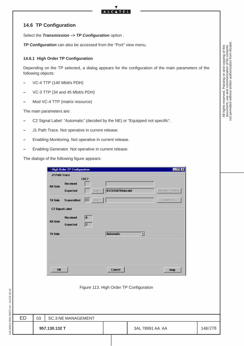
All
right
s re
serv
ed. P
assi
ng o
n an
d co
pyin
g of
this
docu
men
t, us
e an
d co
mm
unic
atio
n of
its
cont
ents
not p
erm
itted
with
out w
ritte
n au
thor
izat
ion
from
Alc
atel
.
ED
1AA
000
14 0
004
(900
7) A
4 –
ALI
CE
04.
10
148
03
957.130.132 T
SC.3:NE MANAGEMENT
/3AL 78991 AA AA
278
278
14.6 TP Configuration
Select the Transmission –> TP Configuration option .
TP Configuration can also be accessed from the “Port” view menu.
14.6.1 High Order TP Configuration
Depending on the TP selected, a dialog appears for the configuration of the main parameters of thefollowing objects:
– VC-4 TTP (140 Mbit/s PDH)
– VC-3 TTP (34 and 45 Mbit/s PDH)
– Mod VC-4 TTP (matrix resource)
The main parameters are:
– C2 Signal Label: “Automatic” (decided by the NE) or “Equipped not specific”.
– J1 Path Trace. Not operative in current release.
– Enabling Monitoring. Not operative in current release.
– Enabling Generator. Not operative in current release.
The dialogs of the following figure appears:
Figure 113. High Order TP Configuration
All
right
s re
serv
ed. P
assi
ng o
n an
d co
pyin
g of
this
docu
men
t, us
e an
d co
mm
unic
atio
n of
its
cont
ents
not p
erm
itted
with
out w
ritte
n au
thor
izat
ion
from
Alc
atel
.
ED
1AA
000
14 0
004
(900
7) A
4 –
ALI
CE
04.
10
149
03
957.130.132 T
SC.3:NE MANAGEMENT
/3AL 78991 AA AA
278
278
14.6.1.1 J1 Path Trace
Not operative in current release.If the Path Trace is 16 bytes long, the first byte is a CRC7 checksum calculated by NE.If the Path Trace is shorter than 16 bytes, it is filled with zero bytes (”0” hexadecimal).Expected and Transmitted fields are editable by the operator.Received fields is read only.With the relevant button it is possible to enable or disable TTI Monitoring.Empty TTI button permits to send an all zeroes path trace.
14.6.1.2 C2 Signal Label
Received, Expected and Transmitted fields are read only.They can display the following number, according the G.707 recommendations for the C2 Signal Label:– 0: Unequipped– 1: Equipped non-specific– 2: TUG structure– 3: Locked TU-n– 4: Asynchronous 34/45Mbyte– 18: Asynchronous 140Mbyte– 19: ATM– 20: MAN, DQDB– 21: FDDI.
In the Transmitted field it is possible to select the values:• Automatic: the C2 Signal Label value is automatically selected by the NE according the VC
structure.• Equipped not specific (it corresponds to number 1)
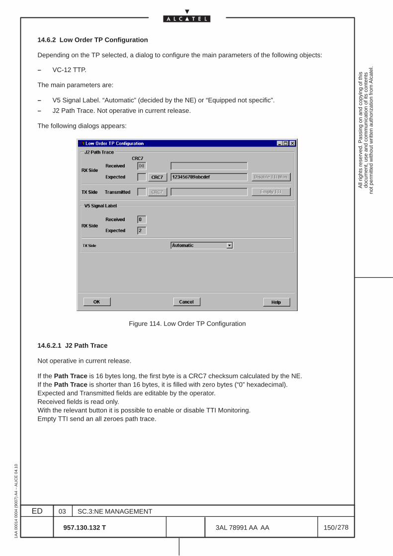
All
right
s re
serv
ed. P
assi
ng o
n an
d co
pyin
g of
this
docu
men
t, us
e an
d co
mm
unic
atio
n of
its
cont
ents
not p
erm
itted
with
out w
ritte
n au
thor
izat
ion
from
Alc
atel
.
ED
1AA
000
14 0
004
(900
7) A
4 –
ALI
CE
04.
10
150
03
957.130.132 T
SC.3:NE MANAGEMENT
/3AL 78991 AA AA
278
278
14.6.2 Low Order TP Configuration
Depending on the TP selected, a dialog to configure the main parameters of the following objects:
– VC-12 TTP.
The main parameters are:
– V5 Signal Label. “Automatic” (decided by the NE) or “Equipped not specific”.
– J2 Path Trace. Not operative in current release.
The following dialogs appears:
Figure 114. Low Order TP Configuration
14.6.2.1 J2 Path Trace
Not operative in current release.
If the Path Trace is 16 bytes long, the first byte is a CRC7 checksum calculated by the NE.If the Path Trace is shorter than 16 bytes, it is filled with zero bytes (“0” hexadecimal).Expected and Transmitted fields are editable by the operator.Received fields is read only.With the relevant button it is possible to enable or disable TTI Monitoring.Empty TTI send an all zeroes path trace.
All
right
s re
serv
ed. P
assi
ng o
n an
d co
pyin
g of
this
docu
men
t, us
e an
d co
mm
unic
atio
n of
its
cont
ents
not p
erm
itted
with
out w
ritte
n au
thor
izat
ion
from
Alc
atel
.
ED
1AA
000
14 0
004
(900
7) A
4 –
ALI
CE
04.
10
151
03
957.130.132 T
SC.3:NE MANAGEMENT
/3AL 78991 AA AA
278
278
14.6.2.2 V5 Signal Label
Received, Expected and Transmitted fields are read only.
They can display the following number, according the G.707 recommendations for the V5 Signal Label:
– 0: Unequipped– 1: Equipped non-specific– 2: Asynchronous– 3: Bit Synchronous– 4: Byte Synchronous
In the Transmitted field it is possible to select the values:
• Automatic: the C2 Signal Label value is automatically selected by the NE according the VCstructure.
• Equipped not specific (it corresponds to number 1)
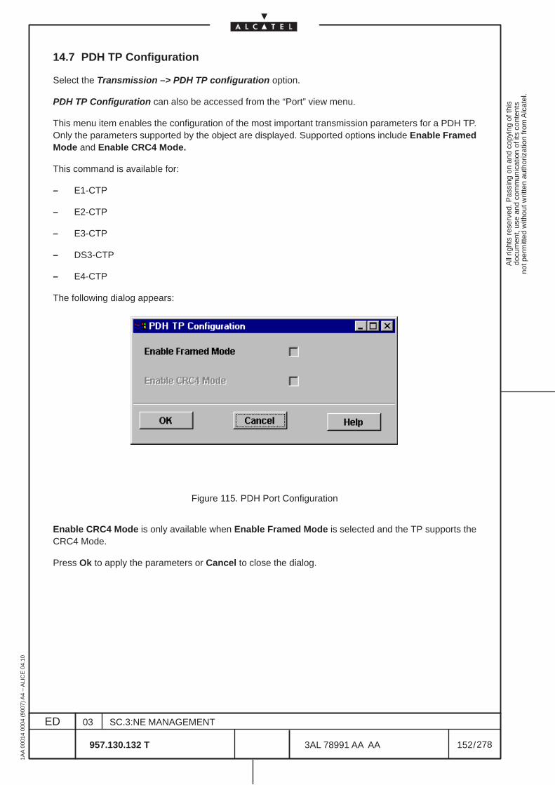
All
right
s re
serv
ed. P
assi
ng o
n an
d co
pyin
g of
this
docu
men
t, us
e an
d co
mm
unic
atio
n of
its
cont
ents
not p
erm
itted
with
out w
ritte
n au
thor
izat
ion
from
Alc
atel
.
ED
1AA
000
14 0
004
(900
7) A
4 –
ALI
CE
04.
10
152
03
957.130.132 T
SC.3:NE MANAGEMENT
/3AL 78991 AA AA
278
278
14.7 PDH TP Configuration
Select the Transmission –> PDH TP configuration option.
PDH TP Configuration can also be accessed from the “Port” view menu.
This menu item enables the configuration of the most important transmission parameters for a PDH TP.Only the parameters supported by the object are displayed. Supported options include Enable FramedMode and Enable CRC4 Mode.
This command is available for:
– E1-CTP
– E2-CTP
– E3-CTP
– DS3-CTP
– E4-CTP
The following dialog appears:
Figure 115. PDH Port Configuration
Enable CRC4 Mode is only available when Enable Framed Mode is selected and the TP supports theCRC4 Mode.
Press Ok to apply the parameters or Cancel to close the dialog.
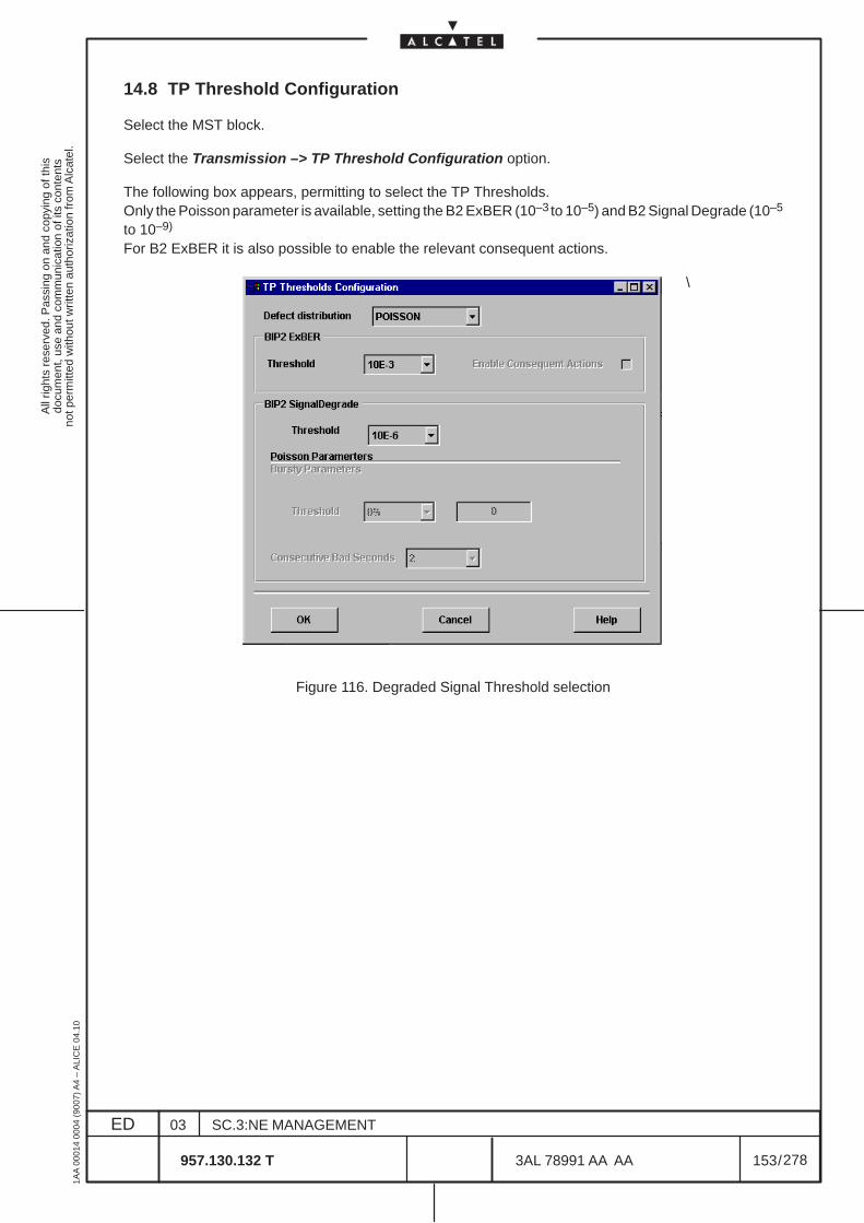
All
right
s re
serv
ed. P
assi
ng o
n an
d co
pyin
g of
this
docu
men
t, us
e an
d co
mm
unic
atio
n of
its
cont
ents
not p
erm
itted
with
out w
ritte
n au
thor
izat
ion
from
Alc
atel
.
ED
1AA
000
14 0
004
(900
7) A
4 –
ALI
CE
04.
10
153
03
957.130.132 T
SC.3:NE MANAGEMENT
/3AL 78991 AA AA
278
278
14.8 TP Threshold Configuration
Select the MST block.
Select the Transmission –> TP Threshold Configuration option.
The following box appears, permitting to select the TP Thresholds.Only the Poisson parameter is available, setting the B2 ExBER (10–3 to 10–5) and B2 Signal Degrade (10–5
to 10–9)
For B2 ExBER it is also possible to enable the relevant consequent actions.
\
Figure 116. Degraded Signal Threshold selection
All
right
s re
serv
ed. P
assi
ng o
n an
d co
pyin
g of
this
docu
men
t, us
e an
d co
mm
unic
atio
n of
its
cont
ents
not p
erm
itted
with
out w
ritte
n au
thor
izat
ion
from
Alc
atel
.
ED
1AA
000
14 0
004
(900
7) A
4 –
ALI
CE
04.
10
154
03
957.130.132 T
SC.3:NE MANAGEMENT
/3AL 78991 AA AA
278
278
14.9 Alarm Persistency Time Configuration
Not operative in current release.
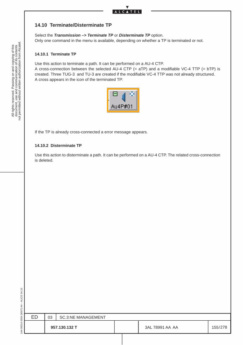
All
right
s re
serv
ed. P
assi
ng o
n an
d co
pyin
g of
this
docu
men
t, us
e an
d co
mm
unic
atio
n of
its
cont
ents
not p
erm
itted
with
out w
ritte
n au
thor
izat
ion
from
Alc
atel
.
ED
1AA
000
14 0
004
(900
7) A
4 –
ALI
CE
04.
10
155
03
957.130.132 T
SC.3:NE MANAGEMENT
/3AL 78991 AA AA
278
278
14.10 Terminate/Disterminate TP
Select the Transmission –> Terminate TP or Disterminate TP option.Only one command in the menu is available, depending on whether a TP is terminated or not.
14.10.1 Terminate TP
Use this action to terminate a path. It can be performed on a AU-4 CTP.A cross-connection between the selected AU-4 CTP (= aTP) and a modifiable VC-4 TTP (= bTP) iscreated. Three TUG-3 and TU-3 are created if the modifiable VC-4 TTP was not already structured.A cross appears in the icon of the terminated TP:
If the TP is already cross-connected a error message appears.
14.10.2 Disterminate TP
Use this action to disterminate a path. It can be performed on a AU-4 CTP. The related cross-connectionis deleted.
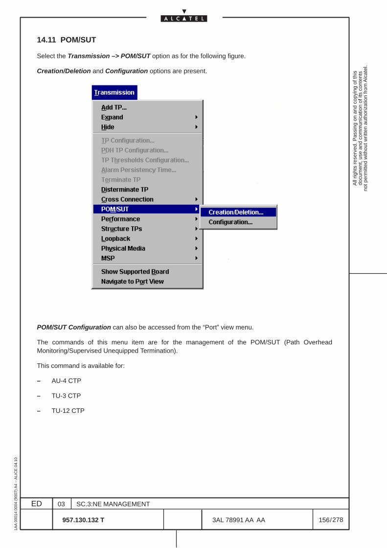
All
right
s re
serv
ed. P
assi
ng o
n an
d co
pyin
g of
this
docu
men
t, us
e an
d co
mm
unic
atio
n of
its
cont
ents
not p
erm
itted
with
out w
ritte
n au
thor
izat
ion
from
Alc
atel
.
ED
1AA
000
14 0
004
(900
7) A
4 –
ALI
CE
04.
10
156
03
957.130.132 T
SC.3:NE MANAGEMENT
/3AL 78991 AA AA
278
278
14.11 POM/SUT
Select the Transmission –> POM/SUT option as for the following figure.
Creation/Deletion and Configuration options are present.
POM/SUT Configuration can also be accessed from the “Port” view menu.
The commands of this menu item are for the management of the POM/SUT (Path OverheadMonitoring/Supervised Unequipped Termination).
This command is available for:
– AU-4 CTP
– TU-3 CTP
– TU-12 CTP
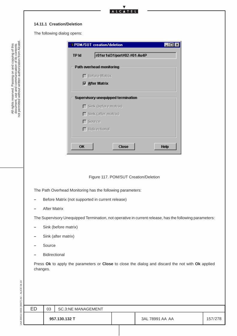
All
right
s re
serv
ed. P
assi
ng o
n an
d co
pyin
g of
this
docu
men
t, us
e an
d co
mm
unic
atio
n of
its
cont
ents
not p
erm
itted
with
out w
ritte
n au
thor
izat
ion
from
Alc
atel
.
ED
1AA
000
14 0
004
(900
7) A
4 –
ALI
CE
04.
10
157
03
957.130.132 T
SC.3:NE MANAGEMENT
/3AL 78991 AA AA
278
278
14.11.1 Creation/Deletion
The following dialog opens:
Figure 117. POM/SUT Creation/Deletion
The Path Overhead Monitoring has the following parameters:
– Before Matrix (not supported in current release)
– After Matrix
The Supervisory Unequipped Termination, not operative in current release, has the following parameters:
– Sink (before matrix)
– Sink (after matrix)
– Source
– Bidirectional
Press Ok to apply the parameters or Close to close the dialog and discard the not with Ok appliedchanges.
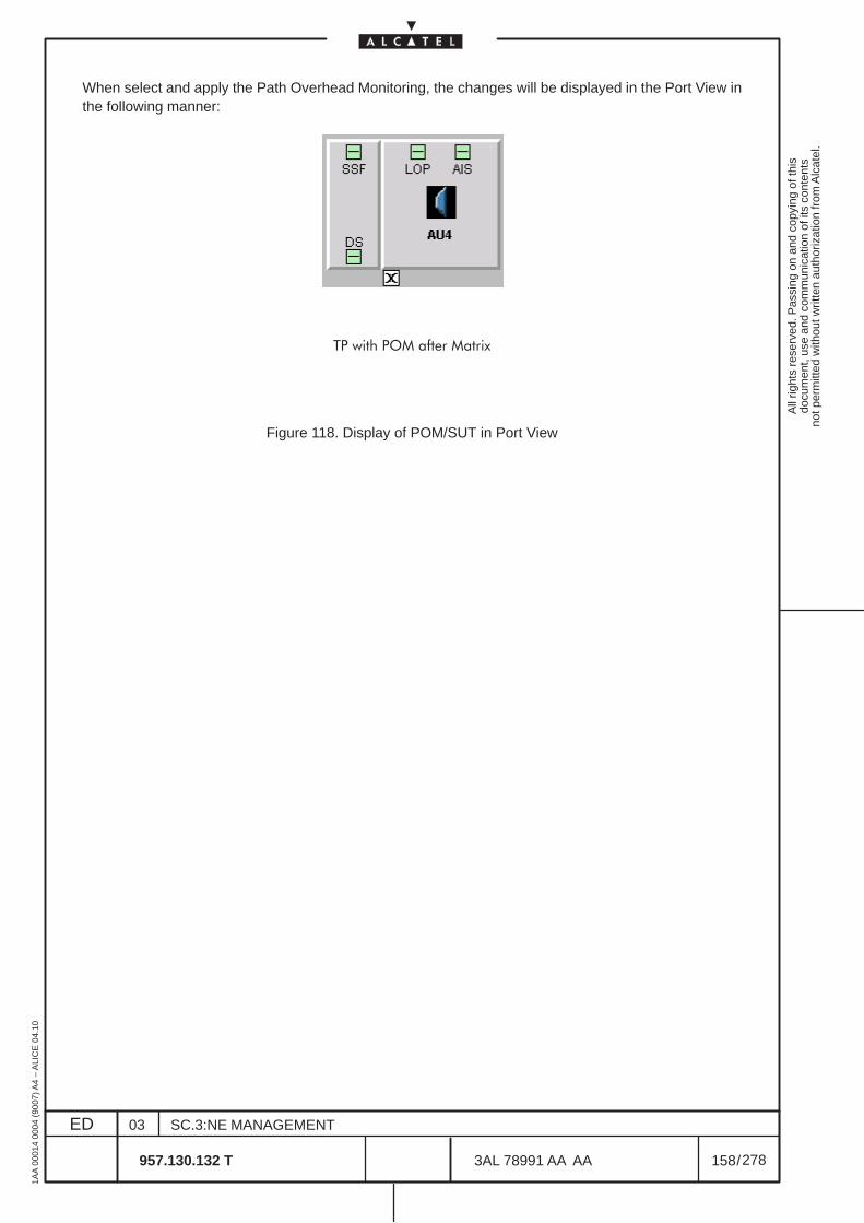
All
right
s re
serv
ed. P
assi
ng o
n an
d co
pyin
g of
this
docu
men
t, us
e an
d co
mm
unic
atio
n of
its
cont
ents
not p
erm
itted
with
out w
ritte
n au
thor
izat
ion
from
Alc
atel
.
ED
1AA
000
14 0
004
(900
7) A
4 –
ALI
CE
04.
10
158
03
957.130.132 T
SC.3:NE MANAGEMENT
/3AL 78991 AA AA
278
278
When select and apply the Path Overhead Monitoring, the changes will be displayed in the Port View inthe following manner:
������ �� !�������!����"
Figure 118. Display of POM/SUT in Port View
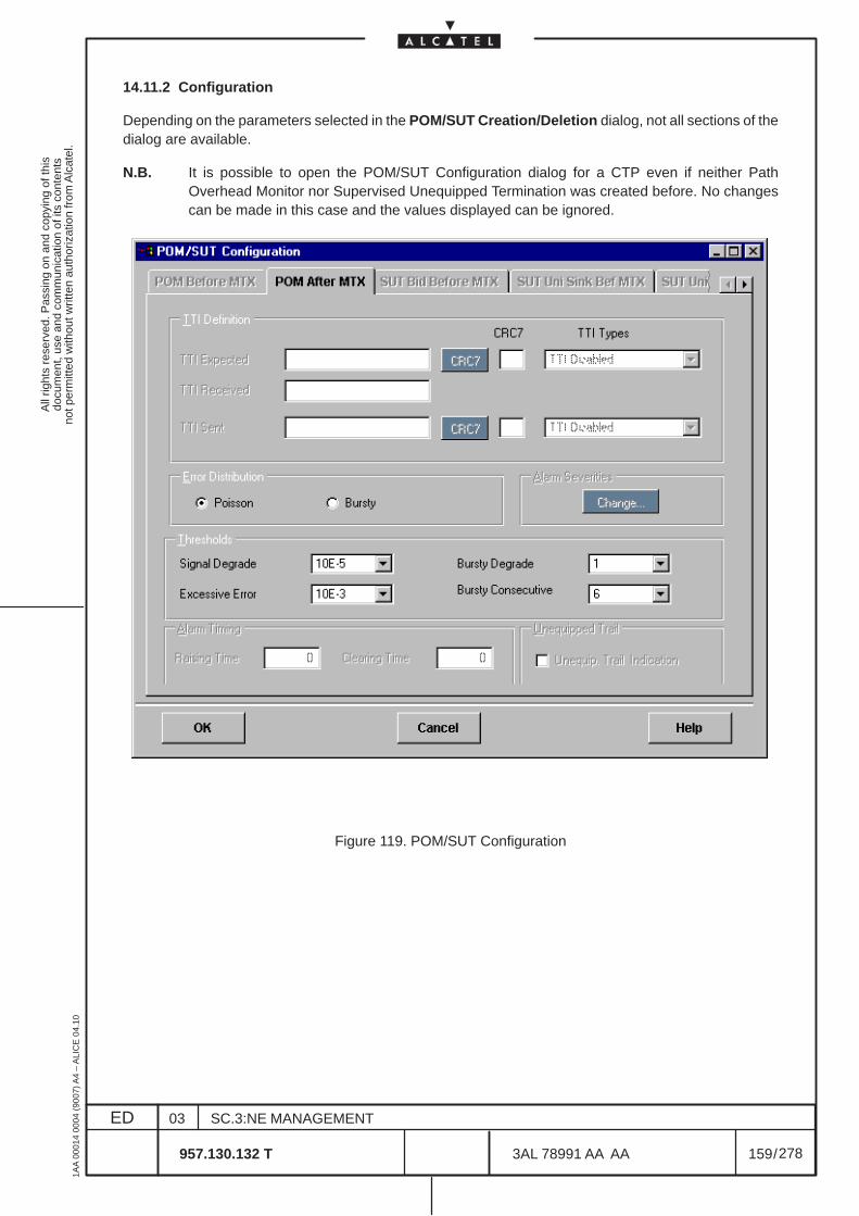
All
right
s re
serv
ed. P
assi
ng o
n an
d co
pyin
g of
this
docu
men
t, us
e an
d co
mm
unic
atio
n of
its
cont
ents
not p
erm
itted
with
out w
ritte
n au
thor
izat
ion
from
Alc
atel
.
ED
1AA
000
14 0
004
(900
7) A
4 –
ALI
CE
04.
10
159
03
957.130.132 T
SC.3:NE MANAGEMENT
/3AL 78991 AA AA
278
278
14.11.2 Configuration
Depending on the parameters selected in the POM/SUT Creation/Deletion dialog, not all sections of thedialog are available.
N.B. It is possible to open the POM/SUT Configuration dialog for a CTP even if neither PathOverhead Monitor nor Supervised Unequipped Termination was created before. No changescan be made in this case and the values displayed can be ignored.
Figure 119. POM/SUT Configuration

All
right
s re
serv
ed. P
assi
ng o
n an
d co
pyin
g of
this
docu
men
t, us
e an
d co
mm
unic
atio
n of
its
cont
ents
not p
erm
itted
with
out w
ritte
n au
thor
izat
ion
from
Alc
atel
.
ED
1AA
000
14 0
004
(900
7) A
4 –
ALI
CE
04.
10
160
03
957.130.132 T
SC.3:NE MANAGEMENT
/3AL 78991 AA AA
278
278
14.11.2.1 TTI Definition
This function is not operative.
The TTI (Trail Trace Identifier) has a maximum length of 16 characters.
The following TTI Definitions are available:
– TTI Expected– TTI Received without the display– TTI Sent
The following TTI Types are available:
– TTI Enabled– TTI Disabled– TTI Continuous
14.11.2.2 Error Distribution
Poisson and Bursty error distribution are supported (Poisson only supported).
14.11.2.3 Alarm Severities
It allows to change the ASAP assigned to the specified POM/SUT.
14.11.2.4 Thresholds
Set the thresholds of the following parameters:
– Signal Degrade
Poisson mode only: from 10–5 to 10–9.
– Excessive Error
Poisson mode only: from 10–3 also if presented a selection from 10–3 to 10–5
– Bursty Degrade
Select a value between 1 and 8000 errors/sec for the Bursty Degrade threshold. Not operative
– Bursty Consecutive
Select a value between 2 and 10 sec for the Bursty Degrade Consecutive. Not operative
14.11.2.5 Alarm Timing
Not available.
14.11.2.6 Unequipped Trail
Not available.
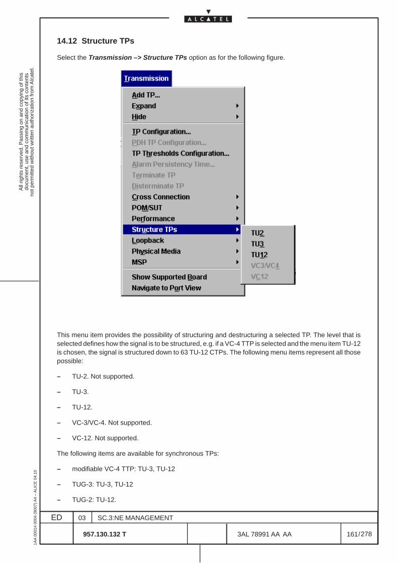
All
right
s re
serv
ed. P
assi
ng o
n an
d co
pyin
g of
this
docu
men
t, us
e an
d co
mm
unic
atio
n of
its
cont
ents
not p
erm
itted
with
out w
ritte
n au
thor
izat
ion
from
Alc
atel
.
ED
1AA
000
14 0
004
(900
7) A
4 –
ALI
CE
04.
10
161
03
957.130.132 T
SC.3:NE MANAGEMENT
/3AL 78991 AA AA
278
278
14.12 Structure TPs
Select the Transmission –> Structure TPs option as for the following figure.
This menu item provides the possibility of structuring and destructuring a selected TP. The level that isselected defines how the signal is to be structured, e.g. if a VC-4 TTP is selected and the menu item TU-12is chosen, the signal is structured down to 63 TU-12 CTPs. The following menu items represent all thosepossible:
– TU-2. Not supported.
– TU-3.
– TU-12.
– VC-3/VC-4. Not supported.
– VC-12. Not supported.
The following items are available for synchronous TPs:
– modifiable VC-4 TTP: TU-3, TU-12
– TUG-3: TU-3, TU-12
– TUG-2: TU-12.
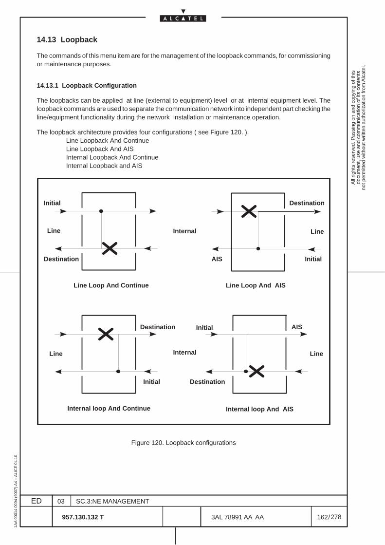
All
right
s re
serv
ed. P
assi
ng o
n an
d co
pyin
g of
this
docu
men
t, us
e an
d co
mm
unic
atio
n of
its
cont
ents
not p
erm
itted
with
out w
ritte
n au
thor
izat
ion
from
Alc
atel
.
ED
1AA
000
14 0
004
(900
7) A
4 –
ALI
CE
04.
10
162
03
957.130.132 T
SC.3:NE MANAGEMENT
/3AL 78991 AA AA
278
278
14.13 Loopback
The commands of this menu item are for the management of the loopback commands, for commissioningor maintenance purposes.
14.13.1 Loopback Configuration
The loopbacks can be applied at line (external to equipment) level or at internal equipment level. Theloopback commands are used to separate the communication network into independent part checking theline/equipment functionality during the network installation or maintenance operation.
The loopback architecture provides four configurations ( see Figure 120. ).Line Loopback And ContinueLine Loopback And AISInternal Loopback And ContinueInternal Loopback and AIS
Line Internal Line
Line
Destination
Destination
Initial
Initial
Destination
AIS
Internal Line
AIS
Internal loop And Continue Internal loop And AIS
Line Loop And Continue Line Loop And AIS
Initial Destination
Initial
Figure 120. Loopback configurations
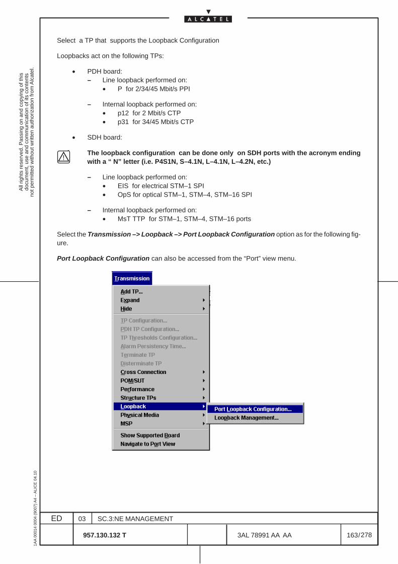
All
right
s re
serv
ed. P
assi
ng o
n an
d co
pyin
g of
this
docu
men
t, us
e an
d co
mm
unic
atio
n of
its
cont
ents
not p
erm
itted
with
out w
ritte
n au
thor
izat
ion
from
Alc
atel
.
ED
1AA
000
14 0
004
(900
7) A
4 –
ALI
CE
04.
10
163
03
957.130.132 T
SC.3:NE MANAGEMENT
/3AL 78991 AA AA
278
278
Select a TP that supports the Loopback Configuration
Loopbacks act on the following TPs:
• PDH board:– Line loopback performed on:
• P for 2/34/45 Mbit/s PPI
– Internal loopback performed on:• p12 for 2 Mbit/s CTP• p31 for 34/45 Mbit/s CTP
• SDH board:
The loopback configuration can be done only on SDH ports with the acronym endingwith a “ N” letter (i.e. P4S1N, S–4.1N, L–4.1N, L–4.2N, etc.)
– Line loopback performed on:• EIS for electrical STM–1 SPI• OpS for optical STM–1, STM–4, STM–16 SPI
– Internal loopback performed on:• MsT TTP for STM–1, STM–4, STM–16 ports
Select the Transmission –> Loopback –> Port Loopback Configuration option as for the following fig-ure.
Port Loopback Configuration can also be accessed from the “Port” view menu.
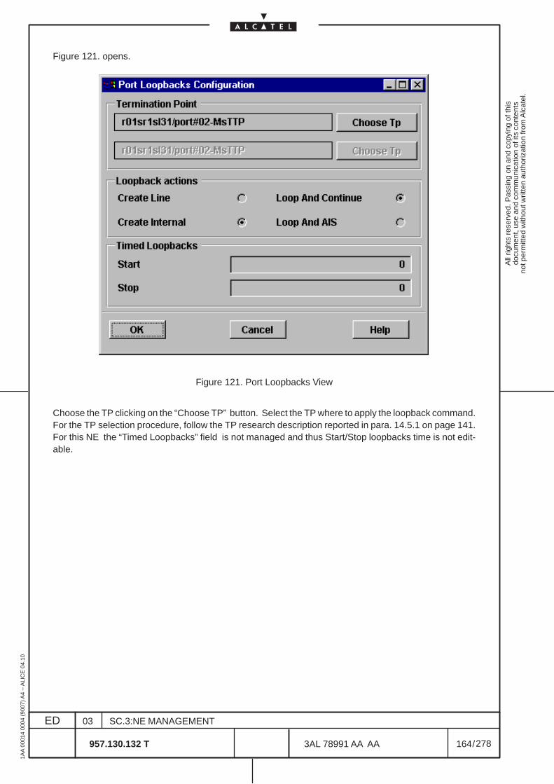
All
right
s re
serv
ed. P
assi
ng o
n an
d co
pyin
g of
this
docu
men
t, us
e an
d co
mm
unic
atio
n of
its
cont
ents
not p
erm
itted
with
out w
ritte
n au
thor
izat
ion
from
Alc
atel
.
ED
1AA
000
14 0
004
(900
7) A
4 –
ALI
CE
04.
10
164
03
957.130.132 T
SC.3:NE MANAGEMENT
/3AL 78991 AA AA
278
278
Figure 121. opens.
Figure 121. Port Loopbacks View
Choose the TP clicking on the “Choose TP” button. Select the TP where to apply the loopback command.For the TP selection procedure, follow the TP research description reported in para. 14.5.1 on page 141.For this NE the “Timed Loopbacks” field is not managed and thus Start/Stop loopbacks time is not edit-able.
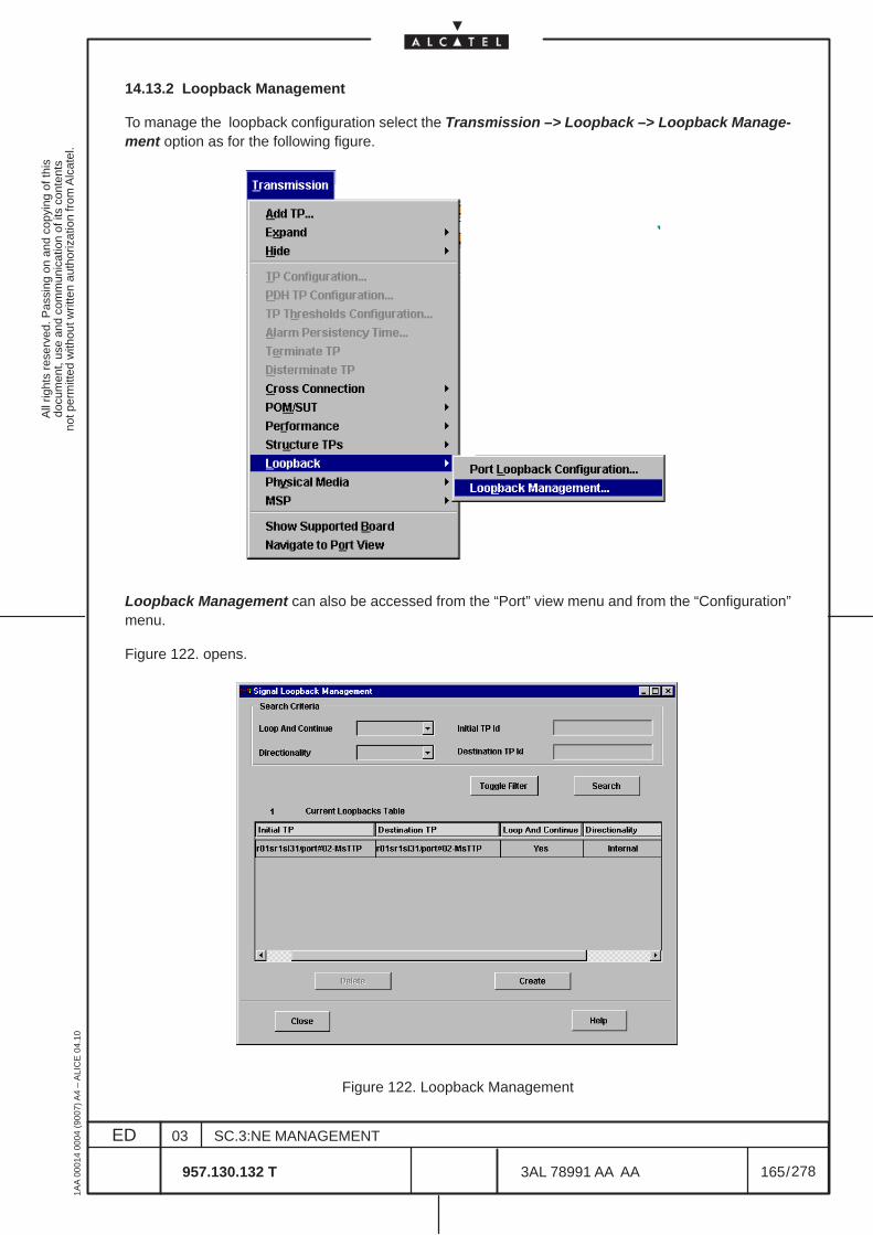
All
right
s re
serv
ed. P
assi
ng o
n an
d co
pyin
g of
this
docu
men
t, us
e an
d co
mm
unic
atio
n of
its
cont
ents
not p
erm
itted
with
out w
ritte
n au
thor
izat
ion
from
Alc
atel
.
ED
1AA
000
14 0
004
(900
7) A
4 –
ALI
CE
04.
10
165
03
957.130.132 T
SC.3:NE MANAGEMENT
/3AL 78991 AA AA
278
278
14.13.2 Loopback Management
To manage the loopback configuration select the Transmission –> Loopback –> Loopback Manage-ment option as for the following figure.
Loopback Management can also be accessed from the “Port” view menu and from the “Configuration”menu.
Figure 122. opens.
Figure 122. Loopback Management
All
right
s re
serv
ed. P
assi
ng o
n an
d co
pyin
g of
this
docu
men
t, us
e an
d co
mm
unic
atio
n of
its
cont
ents
not p
erm
itted
with
out w
ritte
n au
thor
izat
ion
from
Alc
atel
.
ED
1AA
000
14 0
004
(900
7) A
4 –
ALI
CE
04.
10
166
03
957.130.132 T
SC.3:NE MANAGEMENT
/3AL 78991 AA AA
278
278
The configured loopback are listed into the current loopbacks table. This table can be managed by the“Search” criteria, “Delete” and “Create” commands.
– Search Criteria (not operative): to configure the filter select the “Loop and Continue” type (Yes= LoopAnd Continue, No= Loop And AIS) then select the “Directionality” Internal or Line and edit the InitialTP Id (write: rack, subrack, board, port# and the TP type: EIS (SPI/PPI Electrical), OpS (SPI/PPIOptical), MST and so on. For “Initial TP” has to be intended the outgoing signal while for “Destina-tion TP” the incoming signal. Enable the filter through the “Toggle Filter” Enable/Disable button.Click on the “Search” button to start the configured loopback research into the current loopbacktable.
– The “Delete” command permits to delete a loopback listed in the Current loopbacks Table: select aloopback in the list and click on the “Delete” button.
– The “Create” command permits to create a new loopback configuration: clicking on “Create” the pre-vious figure ( Figure 121. ) opens. Follow the previously paragraph indications to create a new loop-back configuration.
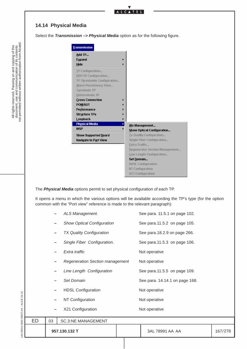
All
right
s re
serv
ed. P
assi
ng o
n an
d co
pyin
g of
this
docu
men
t, us
e an
d co
mm
unic
atio
n of
its
cont
ents
not p
erm
itted
with
out w
ritte
n au
thor
izat
ion
from
Alc
atel
.
ED
1AA
000
14 0
004
(900
7) A
4 –
ALI
CE
04.
10
167
03
957.130.132 T
SC.3:NE MANAGEMENT
/3AL 78991 AA AA
278
278
14.14 Physical Media
Select the Transmission –> Physical Media option as for the following figure.
The Physical Media options permit to set physical configuration of each TP.
It opens a menu in which the various options will be available according the TP’s type (for the optioncommon with the “Port view” reference is made to the relevant paragraph):
– ALS Management. See para. 11.5.1 on page 102.
– Show Optical Configuration See para.11.5.2 on page 105.
– TX Quality Configuration See para.18.2.9 on page 266.
– Single Fiber Configuration. See para.11.5.3 on page 106.
– Extra traffic Not operative
– Regeneration Section management Not operative
– Line Length Configuration See para.11.5.5 on page 109.
– Set Domain See para. 14.14.1 on page 168.
– HDSL Configuration Not operative
– NT Configuration Not operative
– X21 Configuration Not operative
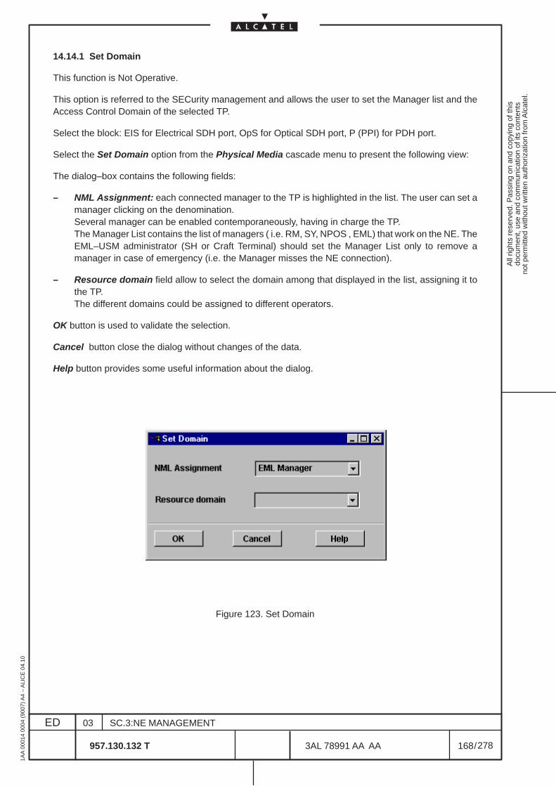
All
right
s re
serv
ed. P
assi
ng o
n an
d co
pyin
g of
this
docu
men
t, us
e an
d co
mm
unic
atio
n of
its
cont
ents
not p
erm
itted
with
out w
ritte
n au
thor
izat
ion
from
Alc
atel
.
ED
1AA
000
14 0
004
(900
7) A
4 –
ALI
CE
04.
10
168
03
957.130.132 T
SC.3:NE MANAGEMENT
/3AL 78991 AA AA
278
278
14.14.1 Set Domain
This function is Not Operative.
This option is referred to the SECurity management and allows the user to set the Manager list and theAccess Control Domain of the selected TP.
Select the block: EIS for Electrical SDH port, OpS for Optical SDH port, P (PPI) for PDH port.
Select the Set Domain option from the Physical Media cascade menu to present the following view:
The dialog–box contains the following fields:
– NML Assignment: each connected manager to the TP is highlighted in the list. The user can set amanager clicking on the denomination.Several manager can be enabled contemporaneously, having in charge the TP.The Manager List contains the list of managers ( i.e. RM, SY, NPOS , EML) that work on the NE. TheEML–USM administrator (SH or Craft Terminal) should set the Manager List only to remove amanager in case of emergency (i.e. the Manager misses the NE connection).
– Resource domain field allow to select the domain among that displayed in the list, assigning it tothe TP.The different domains could be assigned to different operators.
OK button is used to validate the selection.
Cancel button close the dialog without changes of the data.
Help button provides some useful information about the dialog.
Figure 123. Set Domain
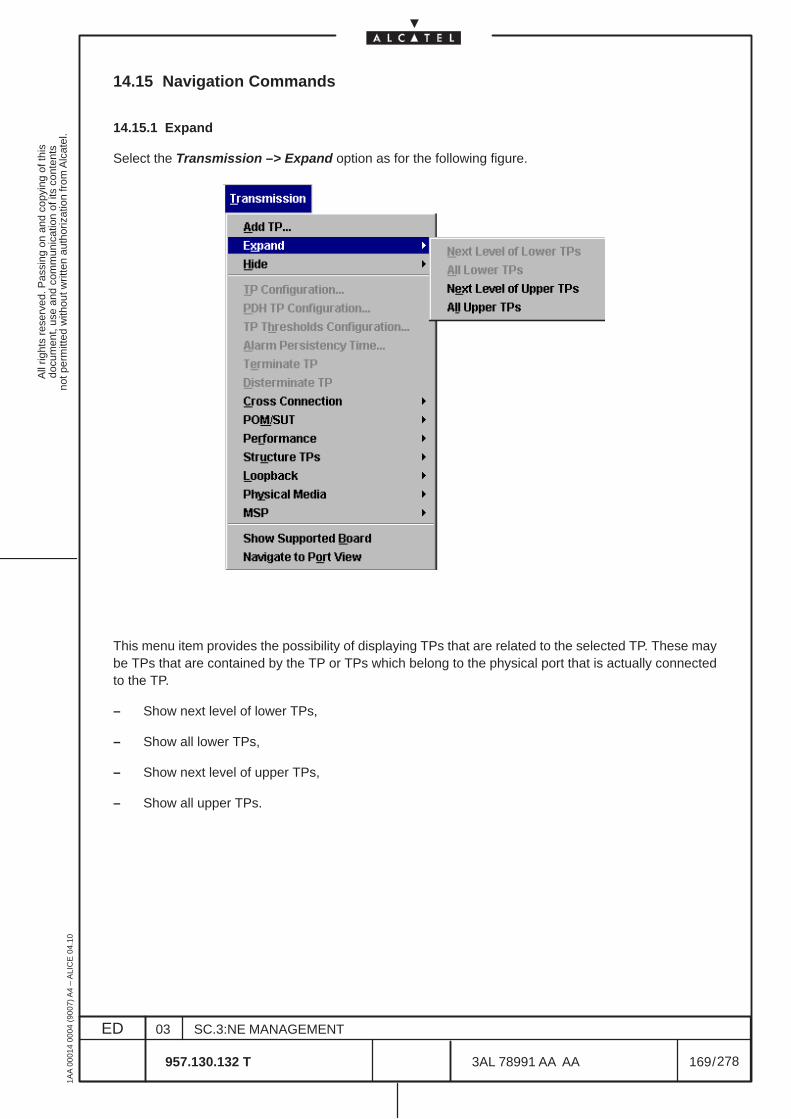
All
right
s re
serv
ed. P
assi
ng o
n an
d co
pyin
g of
this
docu
men
t, us
e an
d co
mm
unic
atio
n of
its
cont
ents
not p
erm
itted
with
out w
ritte
n au
thor
izat
ion
from
Alc
atel
.
ED
1AA
000
14 0
004
(900
7) A
4 –
ALI
CE
04.
10
169
03
957.130.132 T
SC.3:NE MANAGEMENT
/3AL 78991 AA AA
278
278
14.15 Navigation Commands
14.15.1 Expand
Select the Transmission –> Expand option as for the following figure.
This menu item provides the possibility of displaying TPs that are related to the selected TP. These maybe TPs that are contained by the TP or TPs which belong to the physical port that is actually connectedto the TP.
– Show next level of lower TPs,
– Show all lower TPs,
– Show next level of upper TPs,
– Show all upper TPs.
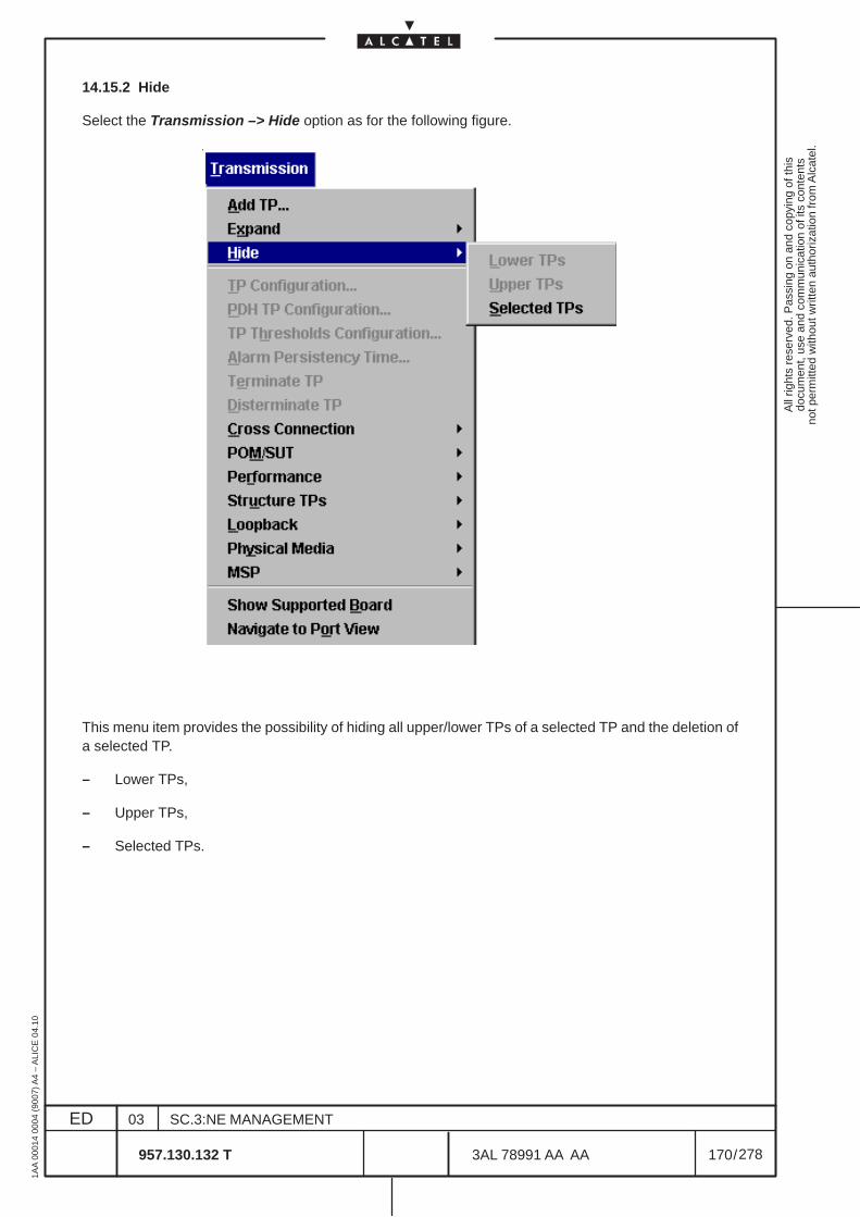
All
right
s re
serv
ed. P
assi
ng o
n an
d co
pyin
g of
this
docu
men
t, us
e an
d co
mm
unic
atio
n of
its
cont
ents
not p
erm
itted
with
out w
ritte
n au
thor
izat
ion
from
Alc
atel
.
ED
1AA
000
14 0
004
(900
7) A
4 –
ALI
CE
04.
10
170
03
957.130.132 T
SC.3:NE MANAGEMENT
/3AL 78991 AA AA
278
278
14.15.2 Hide
Select the Transmission –> Hide option as for the following figure.
This menu item provides the possibility of hiding all upper/lower TPs of a selected TP and the deletion ofa selected TP.
– Lower TPs,
– Upper TPs,
– Selected TPs.
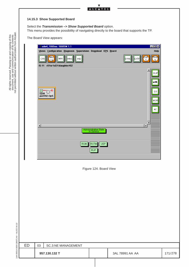
All
right
s re
serv
ed. P
assi
ng o
n an
d co
pyin
g of
this
docu
men
t, us
e an
d co
mm
unic
atio
n of
its
cont
ents
not p
erm
itted
with
out w
ritte
n au
thor
izat
ion
from
Alc
atel
.
ED
1AA
000
14 0
004
(900
7) A
4 –
ALI
CE
04.
10
171
03
957.130.132 T
SC.3:NE MANAGEMENT
/3AL 78991 AA AA
278
278
14.15.3 Show Supported Board
Select the Transmission –> Show Supported Board option.This menu provides the possibility of navigating directly to the board that supports the TP.
The Board View appears:
Figure 124. Board View
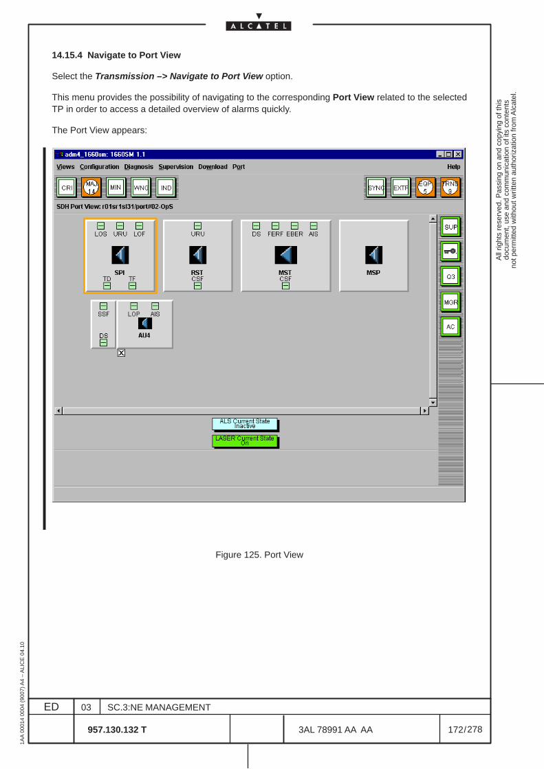
All
right
s re
serv
ed. P
assi
ng o
n an
d co
pyin
g of
this
docu
men
t, us
e an
d co
mm
unic
atio
n of
its
cont
ents
not p
erm
itted
with
out w
ritte
n au
thor
izat
ion
from
Alc
atel
.
ED
1AA
000
14 0
004
(900
7) A
4 –
ALI
CE
04.
10
172
03
957.130.132 T
SC.3:NE MANAGEMENT
/3AL 78991 AA AA
278
278
14.15.4 Navigate to Port View
Select the Transmission –> Navigate to Port View option.
This menu provides the possibility of navigating to the corresponding Port View related to the selectedTP in order to access a detailed overview of alarms quickly.
The Port View appears:
Figure 125. Port View
All
right
s re
serv
ed. P
assi
ng o
n an
d co
pyin
g of
this
docu
men
t, us
e an
d co
mm
unic
atio
n of
its
cont
ents
not p
erm
itted
with
out w
ritte
n au
thor
izat
ion
from
Alc
atel
.
ED
1AA
000
14 0
004
(900
7) A
4 –
ALI
CE
04.
10
173
03
957.130.132 T
SC.3:NE MANAGEMENT
/3AL 78991 AA AA
278
278
15 CROSS-CONNECTION MANAGEMENT
15.1 Introduction
15.1.1 Overview
The purpose of this domain is to manage the connection of the high and low level path.
The following chapters provide the user with information concerning operations on cross-connections:
– Para. 15.1.2 on page 174 “Multiplex Structures for SDH”gives an overview on the SDH technology
– Para. 15.1.3 on page 177 “Definition of Termination Points”gives an overview about the termination points implemented on the NE
– Para. 15.1.4 on page 181 “Cross-Connection Types”provides information concerning cross-connection types supported by the NE
– Para. 15.1.5 on page 183 “Cross-Connection Protection”provides information concerning cross-connection protection supported by the NE
– Para. 15.2 on page 185 “Operative sequence to execute Cross-Connections”details the complete procedure to realize cross-connection
– Para. 15.3 on page 187 “Cross-Connections Management”details the contents of the main cross-connections view
– Para. 15.4 on page 194 “Create/Modify Cross-Connections”describes the creation and modification of cross-connections
– Para. 15.5 on page 209 “Activate/Deactivate/Delete Cross-Connections”describes the activation, deactivation and deletion of cross-connections.Activation and deactivation not supported in current release.
– Para. 15.6 on page 210 “Split and Join Cross-Connections”describes how to split or join bidirectional cross-connections. Not supported in current release.
– Para. 15.7 on page 213 “Protection Switching”deals with switching actions (force, manual, lockout protection) on cross-connections
– Para. 15.8 on page 215 “Print”deals with printing out list entries on printers or into files
– Para. 15.9 on page 216 “Port Switch Over”Not supported in current release.
– Para. 15.10 on page 217 “Show Cross-Connected TPs”describes the possibility of showing connections between two or more TPs of different differenthierarchies, e.g. connection between au4 and vc4.
All
right
s re
serv
ed. P
assi
ng o
n an
d co
pyin
g of
this
docu
men
t, us
e an
d co
mm
unic
atio
n of
its
cont
ents
not p
erm
itted
with
out w
ritte
n au
thor
izat
ion
from
Alc
atel
.
ED
1AA
000
14 0
004
(900
7) A
4 –
ALI
CE
04.
10
174
03
957.130.132 T
SC.3:NE MANAGEMENT
/3AL 78991 AA AA
278
278
15.1.2 Multiplex Structures for SDH
By introducing the Synchronous Digital Hierarchy (SDH), a standardized transmission has been created,matching the European with the American standard. The SDH signal structure contains an extendedoverhead as well as a fixed pointer controlled assignment of the user signal elements, thus improving thepossibilities of the network management.
Signals of the Synchronous and Plesiochronous Digital Hierarchy (PDH) are packed by synchronousmultiplexers into Virtual Containers (VC). The STM-1 signal structure is achieved by using the multiplexstructure complying with ITU-T and ETSI, (see Figure 126. ). Each of the user channels (2 Mbit/s, 34Mbit/s, 45 Mbit/s and 140 Mbit/s) is packed into a container synchronous to the STM-1 frame accordingto a predefined structure.
To adjust the plesiochronous signals to the synchronous network clock, certain filling algorithms areavailable. Fix fill bits are inserted into synchronous signals. A byte column (9 Byte) as Path Overhead(POH) is added to the Container (C) generated. Path Overhead and Container together form the VirtualContainer (VC). With the pointer pointing to the start of the VC, in respect of the STM-1 frame, anAdministrative Unit (AU) or – if several Containers of a group are to be combined – a Tributary Unit (TU)is generated. Several TUs form a Tributary Unit Group (TUG) and TUGs again can be combined into aVC. The AU of the signal, together with the Section Overhead (SOH), finally make up the STM-1 frame.
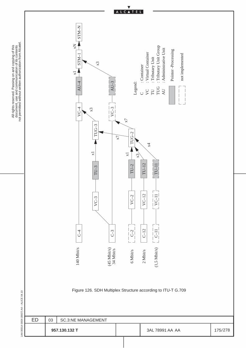
All
right
s re
serv
ed. P
assi
ng o
n an
d co
pyin
g of
this
docu
men
t, us
e an
d co
mm
unic
atio
n of
its
cont
ents
not p
erm
itted
with
out w
ritte
n au
thor
izat
ion
from
Alc
atel
.
ED
1AA
000
14 0
004
(900
7) A
4 –
ALI
CE
04.
10
175
03
957.130.132 T
SC.3:NE MANAGEMENT
/3AL 78991 AA AA
278
278
STM
–NST
M–1
AU
–4V
C–4
C–4
TU
G–3
AU
–3V
C–3
C–3
TU
G–2
TU
–2V
C–2
C–2
TU
–12
VC
–12
C–1
2
TU
–11
VC
–11
C–1
1
TU
–3V
C–3
140
Mbi
t/s
(45
Mbi
t/s)
34 M
bit/s
6 M
bit/s
2 M
bit/s
(1,5
Mbi
t/s)
Leg
end:
C VC
TU
TU
GA
U
: Con
tain
er: V
irtu
al C
onta
iner
: Tri
buta
ry U
nit
: Tri
buta
ry U
nit G
roup
: Adm
inis
trat
ive
Uni
t
x1x3
x3
x3x1
x7
x7
x4
x1xN
Poin
ter
-Pro
cess
ing
not i
mpl
emen
ted
Figure 126. SDH Multiplex Structure according to ITU-T G.709
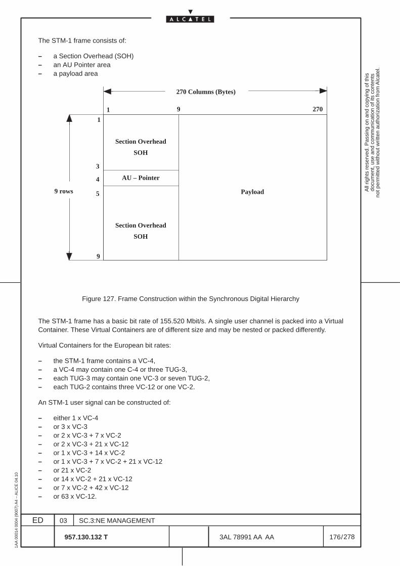
All
right
s re
serv
ed. P
assi
ng o
n an
d co
pyin
g of
this
docu
men
t, us
e an
d co
mm
unic
atio
n of
its
cont
ents
not p
erm
itted
with
out w
ritte
n au
thor
izat
ion
from
Alc
atel
.
ED
1AA
000
14 0
004
(900
7) A
4 –
ALI
CE
04.
10
176
03
957.130.132 T
SC.3:NE MANAGEMENT
/3AL 78991 AA AA
278
278
The STM-1 frame consists of:
– a Section Overhead (SOH)– an AU Pointer area– a payload area
Payload
Section Overhead
SOH
AU – Pointer
Section Overhead
SOH
270 Columns (Bytes)
9 rows
1 9 270
1
9
3
4
5
Figure 127. Frame Construction within the Synchronous Digital Hierarchy
The STM-1 frame has a basic bit rate of 155.520 Mbit/s. A single user channel is packed into a VirtualContainer. These Virtual Containers are of different size and may be nested or packed differently.
Virtual Containers for the European bit rates:
– the STM-1 frame contains a VC-4,– a VC-4 may contain one C-4 or three TUG-3,– each TUG-3 may contain one VC-3 or seven TUG-2,– each TUG-2 contains three VC-12 or one VC-2.
An STM-1 user signal can be constructed of:
– either 1 x VC-4– or 3 x VC-3– or 2 x VC-3 + 7 x VC-2– or 2 x VC-3 + 21 x VC-12– or 1 x VC-3 + 14 x VC-2– or 1 x VC-3 + 7 x VC-2 + 21 x VC-12– or 21 x VC-2– or 14 x VC-2 + 21 x VC-12– or 7 x VC-2 + 42 x VC-12– or 63 x VC-12.
All
right
s re
serv
ed. P
assi
ng o
n an
d co
pyin
g of
this
docu
men
t, us
e an
d co
mm
unic
atio
n of
its
cont
ents
not p
erm
itted
with
out w
ritte
n au
thor
izat
ion
from
Alc
atel
.
ED
1AA
000
14 0
004
(900
7) A
4 –
ALI
CE
04.
10
177
03
957.130.132 T
SC.3:NE MANAGEMENT
/3AL 78991 AA AA
278
278
STM-N signals are constructed by integer multiples of the basic signal STM-1 of 155.520 Mbit/s. Forexample an STM-16 signal of 2.488.320 Mbit/s is generated by combining sixteen STM-1 signals byteinterleaved.
15.1.3 Definition of Termination Points (TP)
When ports are depicted on the user interface, the following abbreviations are used.
This section concerns the multiplex structure (see Figure 126. ) as well as on the information model ofobject-oriented programming which was used when forming the user interface. As a rule, a TerminationPoint (TP) is the starting and terminating point of a transmission segment. A distinction is made betweenthe following types of TPs:
– CTP (Connection Termination Point)The CTP represents the termination of a connection. The transmission signal is ”terminated”, i.e.,the received signal is monitored and the error signaling evaluated, while own-code signaling isinserted in the transmitted signal.
– TTP (Trail Termination Point)The TTP represents the termination of a transmission segment. The signal is monitored and passedon after modification in one form or another.
Both TP types exist on the SDH level and the PDH level.
– CTPs on SDH level
On SDH level (see Figure 128. ) a distinction is made between the following CTPs:
• au4 (au4 Connection Termination Point)The au4CTP represents both the creation and termination of an STM-1 connection. TheHigh-order Connection Supervision (HCS) function is included.
• tux (tux Connection Termination Point), e.g. tu12CTP, tu3CTP.The tuxCTP represents both the creation and termination of a vcx connection. The Low-orderConnection Supervision (LCS) function is included.
– CTPs on PDH level
On PDH level (see Figure 129. ), a distinction is made between the following CTPs:
• e4CTP (e4 Connection Termination Point)The e4CTP represents both the creation and termination of a 140 Mbit/s connection.
• e3CTP (e3 Connection Termination Point)The e3CTP represents both the creation and termination of a 34 Mbit/s connection.
• DS3CTP (e3 Connection Termination Point)The DS3CTP represents both the creation and termination of a 45 Mbit/s connection.
• e1CTP (e1 Connection Termination Point)The e1CTP represents both the creation and termination of a 2 Mbit/s connection.
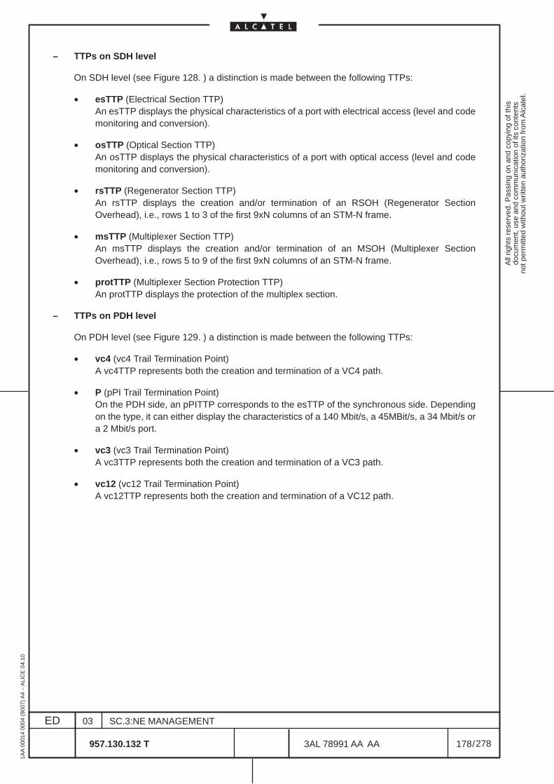
All
right
s re
serv
ed. P
assi
ng o
n an
d co
pyin
g of
this
docu
men
t, us
e an
d co
mm
unic
atio
n of
its
cont
ents
not p
erm
itted
with
out w
ritte
n au
thor
izat
ion
from
Alc
atel
.
ED
1AA
000
14 0
004
(900
7) A
4 –
ALI
CE
04.
10
178
03
957.130.132 T
SC.3:NE MANAGEMENT
/3AL 78991 AA AA
278
278
– TTPs on SDH level
On SDH level (see Figure 128. ) a distinction is made between the following TTPs:
• esTTP (Electrical Section TTP)An esTTP displays the physical characteristics of a port with electrical access (level and codemonitoring and conversion).
• osTTP (Optical Section TTP)An osTTP displays the physical characteristics of a port with optical access (level and codemonitoring and conversion).
• rsTTP (Regenerator Section TTP)An rsTTP displays the creation and/or termination of an RSOH (Regenerator SectionOverhead), i.e., rows 1 to 3 of the first 9xN columns of an STM-N frame.
• msTTP (Multiplexer Section TTP)An msTTP displays the creation and/or termination of an MSOH (Multiplexer SectionOverhead), i.e., rows 5 to 9 of the first 9xN columns of an STM-N frame.
• protTTP (Multiplexer Section Protection TTP)An protTTP displays the protection of the multiplex section.
– TTPs on PDH level
On PDH level (see Figure 129. ) a distinction is made between the following TTPs:
• vc4 (vc4 Trail Termination Point)A vc4TTP represents both the creation and termination of a VC4 path.
• P (pPI Trail Termination Point)On the PDH side, an pPITTP corresponds to the esTTP of the synchronous side. Dependingon the type, it can either display the characteristics of a 140 Mbit/s, a 45MBit/s, a 34 Mbit/s ora 2 Mbit/s port.
• vc3 (vc3 Trail Termination Point)A vc3TTP represents both the creation and termination of a VC3 path.
• vc12 (vc12 Trail Termination Point)A vc12TTP represents both the creation and termination of a VC12 path.
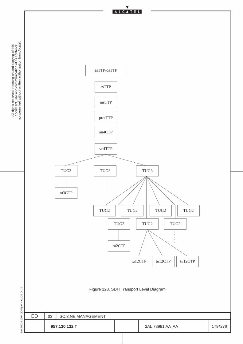
All
right
s re
serv
ed. P
assi
ng o
n an
d co
pyin
g of
this
docu
men
t, us
e an
d co
mm
unic
atio
n of
its
cont
ents
not p
erm
itted
with
out w
ritte
n au
thor
izat
ion
from
Alc
atel
.
ED
1AA
000
14 0
004
(900
7) A
4 –
ALI
CE
04.
10
179
03
957.130.132 T
SC.3:NE MANAGEMENT
/3AL 78991 AA AA
278
278
esTTP/osTTP
rsTTP
vc4TTP
TUG3
tu3CTP
TUG2
tu2CTP
tu12CTP
msTTP
TUG3 TUG3
TUG2
TUG2TUG2TUG2
TUG2 TUG2
tu12CTPtu12CTP
protTTP
au4CTP
Figure 128. SDH Transport Level Diagram
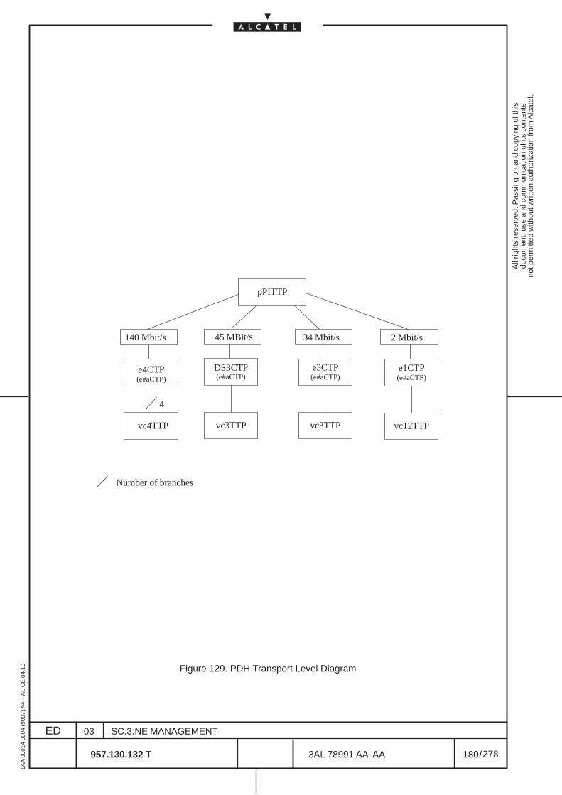
All
right
s re
serv
ed. P
assi
ng o
n an
d co
pyin
g of
this
docu
men
t, us
e an
d co
mm
unic
atio
n of
its
cont
ents
not p
erm
itted
with
out w
ritte
n au
thor
izat
ion
from
Alc
atel
.
ED
1AA
000
14 0
004
(900
7) A
4 –
ALI
CE
04.
10
180
03
957.130.132 T
SC.3:NE MANAGEMENT
/3AL 78991 AA AA
278
278
e4CTP
vc4TTP
e3CTP
vc3TTP vc12TTP
e1CTP
4
Number of branches
140 Mbit/s 2 Mbit/s
pPITTP
34 Mbit/s
vc3TTP
DS3CTP
45 MBit/s
(e#aCTP) (e#aCTP) (e#aCTP) (e#aCTP)
Figure 129. PDH Transport Level Diagram
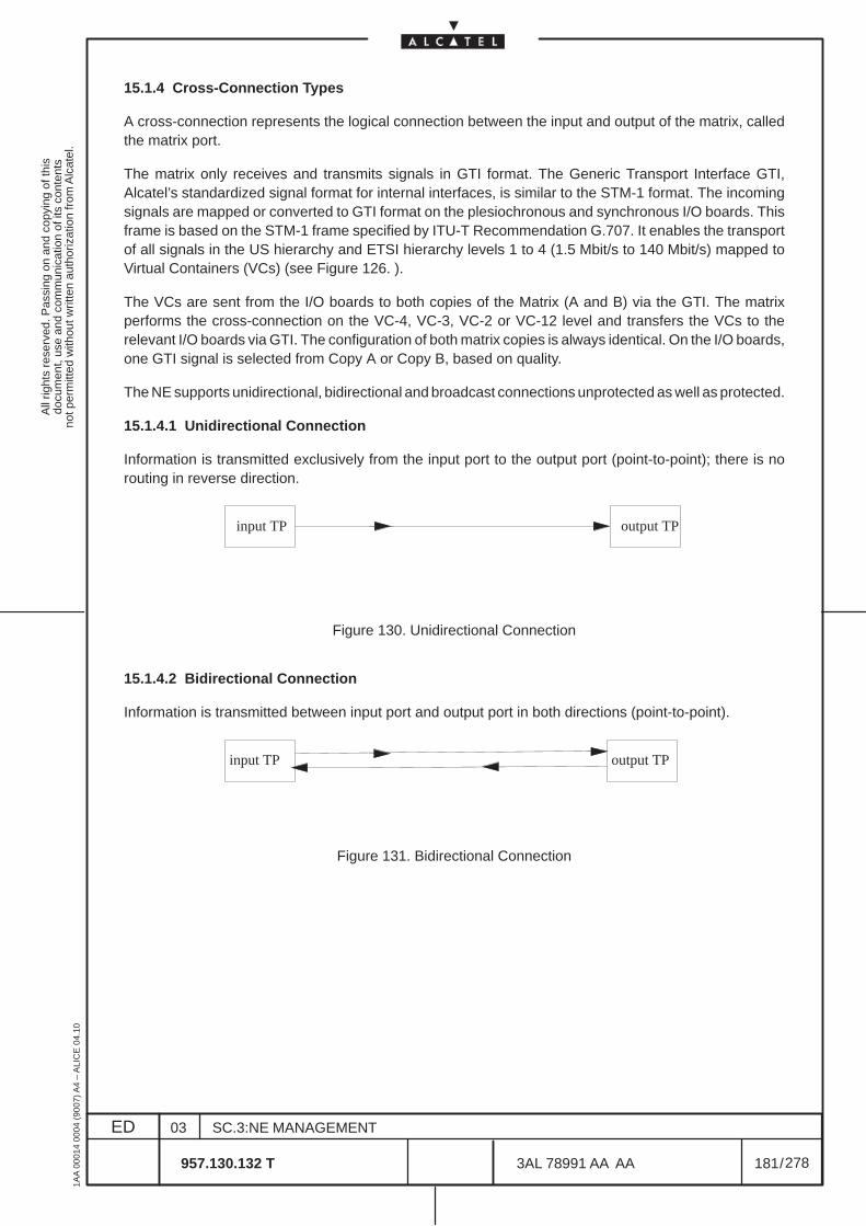
All
right
s re
serv
ed. P
assi
ng o
n an
d co
pyin
g of
this
docu
men
t, us
e an
d co
mm
unic
atio
n of
its
cont
ents
not p
erm
itted
with
out w
ritte
n au
thor
izat
ion
from
Alc
atel
.
ED
1AA
000
14 0
004
(900
7) A
4 –
ALI
CE
04.
10
181
03
957.130.132 T
SC.3:NE MANAGEMENT
/3AL 78991 AA AA
278
278
15.1.4 Cross-Connection Types
A cross-connection represents the logical connection between the input and output of the matrix, calledthe matrix port.
The matrix only receives and transmits signals in GTI format. The Generic Transport Interface GTI,Alcatel’s standardized signal format for internal interfaces, is similar to the STM-1 format. The incomingsignals are mapped or converted to GTI format on the plesiochronous and synchronous I/O boards. Thisframe is based on the STM-1 frame specified by ITU-T Recommendation G.707. It enables the transportof all signals in the US hierarchy and ETSI hierarchy levels 1 to 4 (1.5 Mbit/s to 140 Mbit/s) mapped toVirtual Containers (VCs) (see Figure 126. ).
The VCs are sent from the I/O boards to both copies of the Matrix (A and B) via the GTI. The matrixperforms the cross-connection on the VC-4, VC-3, VC-2 or VC-12 level and transfers the VCs to therelevant I/O boards via GTI. The configuration of both matrix copies is always identical. On the I/O boards,one GTI signal is selected from Copy A or Copy B, based on quality.
The NE supports unidirectional, bidirectional and broadcast connections unprotected as well as protected.
15.1.4.1 Unidirectional Connection
Information is transmitted exclusively from the input port to the output port (point-to-point); there is norouting in reverse direction.
ÀÀÀÀÀÀÀÀÀÀÀÀ
ÈÈÈÈÈÈÈÈÈÈÈÈ
input TP output TP
Figure 130. Unidirectional Connection
15.1.4.2 Bidirectional Connection
Information is transmitted between input port and output port in both directions (point-to-point).
ÀÀÀÀÀÀÀÀ
ÈÈÈÈÈÈÈÈ
input TP output TP
Figure 131. Bidirectional Connection

All
right
s re
serv
ed. P
assi
ng o
n an
d co
pyin
g of
this
docu
men
t, us
e an
d co
mm
unic
atio
n of
its
cont
ents
not p
erm
itted
with
out w
ritte
n au
thor
izat
ion
from
Alc
atel
.
ED
1AA
000
14 0
004
(900
7) A
4 –
ALI
CE
04.
10
182
03
957.130.132 T
SC.3:NE MANAGEMENT
/3AL 78991 AA AA
278
278
15.1.4.3 Broadcast Connection (Multi-leg / Multipoint)
In contrast to a cross-connection between just two points (point-to-point), one source and one sink, abroadcast connection consist of one source and several sinks, different ‘legs’ that share the same sourceTP.
In the example below, information is broadcast from one input to outputs A, B and C on three legs.
ÀÀÀÀÀÀÀÀÀÀÀÀ
ÈÈÈÈÈÈÈÈÈÈÈÈ
input TPÈÈÈÈÈÈÈÈÈÈÈÈÈÈÈÈÈÈÈÈÈÈÈÈ
output A
output B
output C
leg 1
leg 2
leg 3
Figure 132. Example of Broadcast Connection with Three Legs
A warning box indicates when the resources available for broadcast connections are exhausted.
N.B. Non-intrusive MonitoringAdding a protection leg to a unidirectional cross-connection offers the ability to performnon-intrusive monitoring on this cross-connection. No errors are introduced to the originalcross-connection with applying or removing the protection leg.
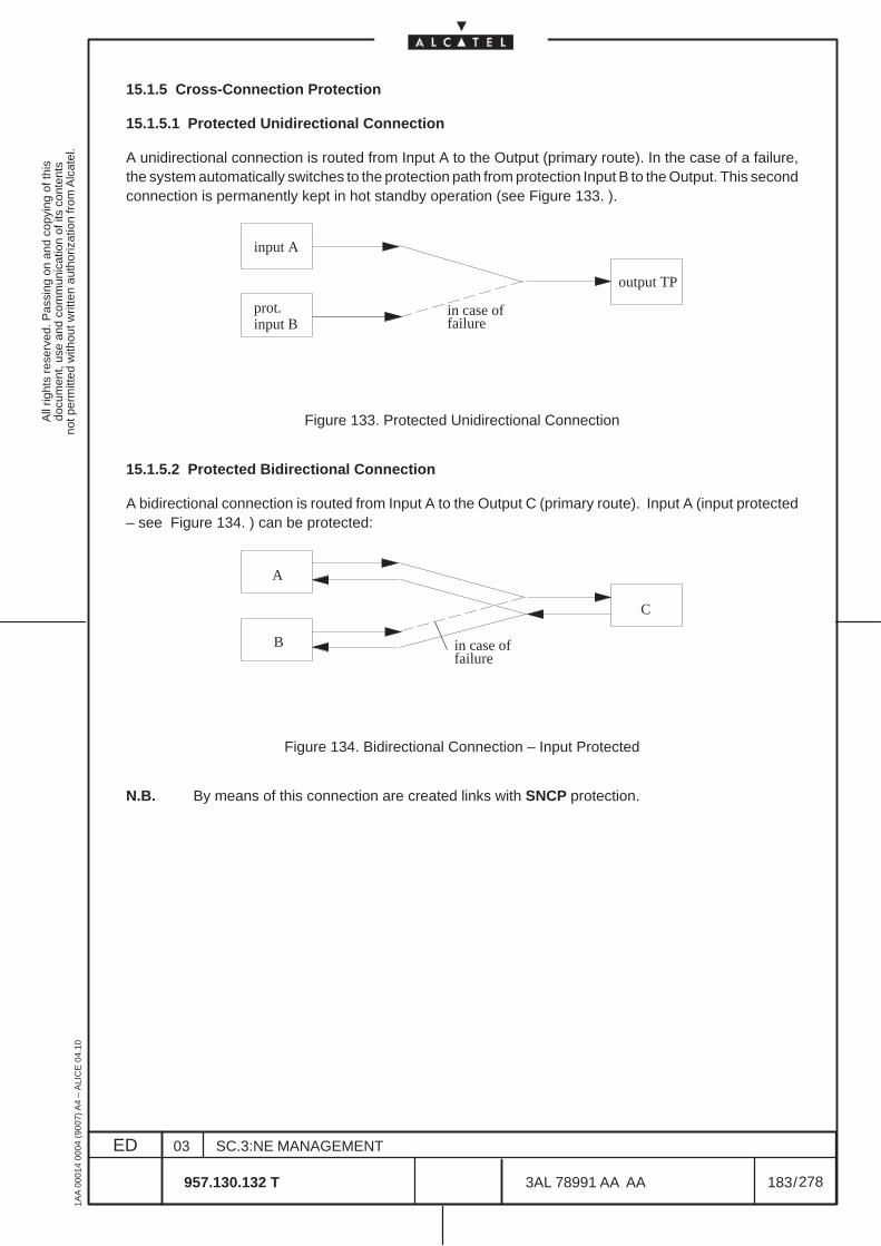
All
right
s re
serv
ed. P
assi
ng o
n an
d co
pyin
g of
this
docu
men
t, us
e an
d co
mm
unic
atio
n of
its
cont
ents
not p
erm
itted
with
out w
ritte
n au
thor
izat
ion
from
Alc
atel
.
ED
1AA
000
14 0
004
(900
7) A
4 –
ALI
CE
04.
10
183
03
957.130.132 T
SC.3:NE MANAGEMENT
/3AL 78991 AA AA
278
278
15.1.5 Cross-Connection Protection
15.1.5.1 Protected Unidirectional Connection
A unidirectional connection is routed from Input A to the Output (primary route). In the case of a failure,the system automatically switches to the protection path from protection Input B to the Output. This secondconnection is permanently kept in hot standby operation (see Figure 133. ).
in case of
ÈÈÈÈÈÈÈÈÈÈÈÈÈÈÈÈÈÈÈÈÈÈÈÈ
ÈÈÈÈÈÈÈÈÈÈÈÈprot.
input B
input A
output TP
failure
Figure 133. Protected Unidirectional Connection
15.1.5.2 Protected Bidirectional Connection
A bidirectional connection is routed from Input A to the Output C (primary route). Input A (input protected– see Figure 134. ) can be protected:
ÈÈÈÈÈÈÈÈÈÈÈÈÈÈÈÈÈÈÈÈÈÈÈÈ
ÈÈÈÈÈÈÈÈÈÈÈÈ
A
B
C
in case of failure
Figure 134. Bidirectional Connection – Input Protected
N.B. By means of this connection are created links with SNCP protection.
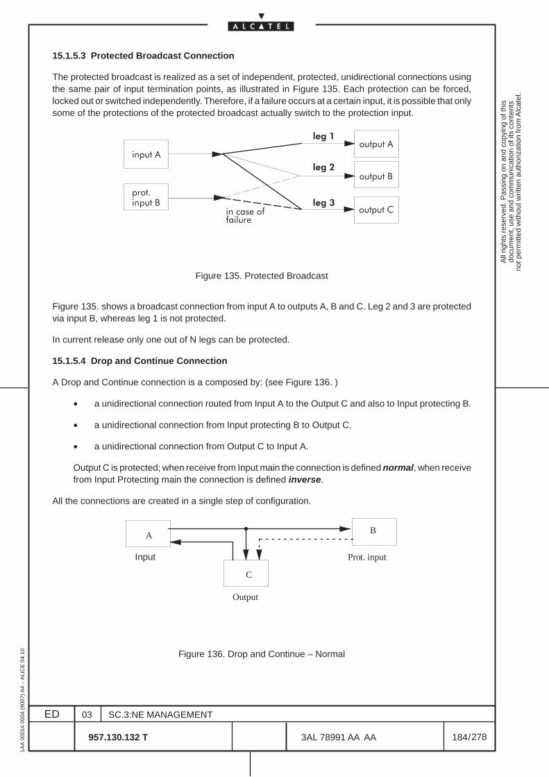
All
right
s re
serv
ed. P
assi
ng o
n an
d co
pyin
g of
this
docu
men
t, us
e an
d co
mm
unic
atio
n of
its
cont
ents
not p
erm
itted
with
out w
ritte
n au
thor
izat
ion
from
Alc
atel
.
ED
1AA
000
14 0
004
(900
7) A
4 –
ALI
CE
04.
10
184
03
957.130.132 T
SC.3:NE MANAGEMENT
/3AL 78991 AA AA
278
278
15.1.5.3 Protected Broadcast Connection
The protected broadcast is realized as a set of independent, protected, unidirectional connections usingthe same pair of input termination points, as illustrated in Figure 135. Each protection can be forced,locked out or switched independently. Therefore, if a failure occurs at a certain input, it is possible that onlysome of the protections of the protected broadcast actually switch to the protection input.
����������
ÈÈÈÈÈÈÈÈÈÈÈÈÈÈÈÈÈÈÈÈÈÈÈÈ
ÈÈÈÈÈÈÈÈÈÈÈÈ����#
����� �
����� �
������ �
�������
ÈÈÈÈÈÈÈÈÈÈÈÈ
������ �
ÈÈÈÈÈÈÈÈÈÈÈÈ������ �
��� �
��� �
��� �
Figure 135. Protected Broadcast
Figure 135. shows a broadcast connection from input A to outputs A, B and C. Leg 2 and 3 are protectedvia input B, whereas leg 1 is not protected.
In current release only one out of N legs can be protected.
15.1.5.4 Drop and Continue Connection
A Drop and Continue connection is a composed by: (see Figure 136. )
• a unidirectional connection routed from Input A to the Output C and also to Input protecting B.
• a unidirectional connection from Input protecting B to Output C.
• a unidirectional connection from Output C to Input A.
Output C is protected; when receive from Input main the connection is defined normal, when receivefrom Input Protecting main the connection is defined inverse.
All the connections are created in a single step of configuration.
ÈÈÈÈÈÈÈÈÈÈÈÈÈÈÈ
ÈÈÈÈÈÈÈÈÈÈÈÈ
ÈÈÈÈÈÈÈÈÈÈÈÈ
A
Input Pro
Output
t. input
B
C
Figure 136. Drop and Continue – Normal
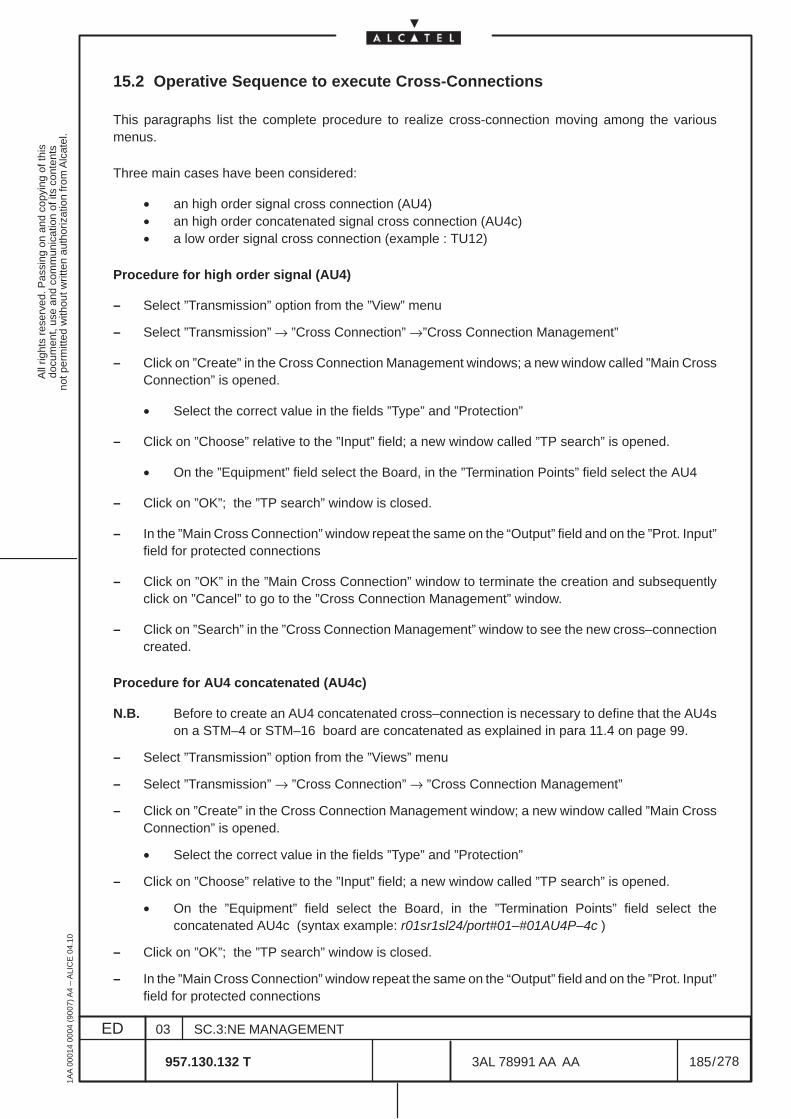
All
right
s re
serv
ed. P
assi
ng o
n an
d co
pyin
g of
this
docu
men
t, us
e an
d co
mm
unic
atio
n of
its
cont
ents
not p
erm
itted
with
out w
ritte
n au
thor
izat
ion
from
Alc
atel
.
ED
1AA
000
14 0
004
(900
7) A
4 –
ALI
CE
04.
10
185
03
957.130.132 T
SC.3:NE MANAGEMENT
/3AL 78991 AA AA
278
278
15.2 Operative Sequence to execute Cross-Connections
This paragraphs list the complete procedure to realize cross-connection moving among the variousmenus.
Three main cases have been considered:
• an high order signal cross connection (AU4)• an high order concatenated signal cross connection (AU4c)• a low order signal cross connection (example : TU12)
Procedure for high order signal (AU4)
– Select ”Transmission” option from the ”View” menu
– Select ”Transmission” → ”Cross Connection” →”Cross Connection Management”
– Click on ”Create” in the Cross Connection Management windows; a new window called ”Main CrossConnection” is opened.
• Select the correct value in the fields ”Type” and ”Protection”
– Click on ”Choose” relative to the ”Input” field; a new window called ”TP search” is opened.
• On the ”Equipment” field select the Board, in the ”Termination Points” field select the AU4
– Click on ”OK”; the ”TP search” window is closed.
– In the ”Main Cross Connection” window repeat the same on the “Output” field and on the ”Prot. Input”field for protected connections
– Click on ”OK” in the ”Main Cross Connection” window to terminate the creation and subsequentlyclick on ”Cancel” to go to the ”Cross Connection Management” window.
– Click on ”Search” in the ”Cross Connection Management” window to see the new cross–connectioncreated.
Procedure for AU4 concatenated (AU4c)
N.B. Before to create an AU4 concatenated cross–connection is necessary to define that the AU4son a STM–4 or STM–16 board are concatenated as explained in para 11.4 on page 99.
– Select ”Transmission” option from the ”Views” menu
– Select ”Transmission” → ”Cross Connection” → ”Cross Connection Management”
– Click on ”Create” in the Cross Connection Management window; a new window called ”Main CrossConnection” is opened.
• Select the correct value in the fields ”Type” and ”Protection”
– Click on ”Choose” relative to the ”Input” field; a new window called ”TP search” is opened.
• On the ”Equipment” field select the Board, in the ”Termination Points” field select theconcatenated AU4c (syntax example: r01sr1sl24/port#01–#01AU4P–4c )
– Click on ”OK”; the ”TP search” window is closed.
– In the ”Main Cross Connection” window repeat the same on the “Output” field and on the ”Prot. Input”field for protected connections

All
right
s re
serv
ed. P
assi
ng o
n an
d co
pyin
g of
this
docu
men
t, us
e an
d co
mm
unic
atio
n of
its
cont
ents
not p
erm
itted
with
out w
ritte
n au
thor
izat
ion
from
Alc
atel
.
ED
1AA
000
14 0
004
(900
7) A
4 –
ALI
CE
04.
10
186
03
957.130.132 T
SC.3:NE MANAGEMENT
/3AL 78991 AA AA
278
278
– Click on ”OK” in the ”Main Cross Connection” window to terminate the creation and subsequentlyclick on ”Cancel” to go to the ”Cross Connection Management” window.
– Click on ”Search” in the ”Cross Connection Management” window to see the new cross–connectioncreated.
Procedure low order signal (example TU12)
– Select ”Transmission” option from the ”View” menu
– Select ”Transmission” →”Add TP”; a new window called ”Tp search” is opened.
• On the ”Equipment” field select the Board, In the ”Termination Points” field select the AU4 andclick on ”OK”;In the transmission window the AU4 block is displayed;
– Select ”Transmission” → ”Terminate TP” ; a cross is displayed on the AU4 block
– Click twice on the AU4 block and on the VC4 block that appears, then selecting the showed TUG3
– Select ”Transmission” → ”Structure TPs” → then selecting the structure
N.B. The AU4 is then terminated on a VC4 of the MATRIX unit.The VC4 is automatically choosed and indicated as “port # n”, where “n” is the VC4number.This connection will appear on the Cross Connection Management view in a independentline.
– If TU12 (example) are selected, in the transmission window clicking twice on the TUG3 and TUG2blocks the TU12 are displayed
– Select the TU12 to be used
– Select ”Transmission” → ”Cross Connection” → ”Cross Connection Management”; a new windowcalled ”Cross Connection Management” is opened.
– In the ”Cross Connection Management” window click on ”Create” button; a new window called ”MainCross Connection” is opened.
• Select the correct value in the fields ”Type” and ”Protection”
– Click on ”Choose” relative to the ”Input” field; a new window called ”TP search” is opened.
• On the ”Equipment” field select the Board, In the ”Termination Points” field select the structuredTP (example: TU12 1.1.1)
– Click on ”OK”; the ”TP search” window is closed.
– Repeat the same on the “Output” field and on the ”Prot. Input” field for protected connections
– Click on ”OK” in the ”Main Cross Connection” window to terminate the creation and subsequentlyclick on ”Cancel” to go to the ”Cross Connection Management” window.
– Click on ”Search” in the ”Cross Connection Management” window to see the new cross–connectioncreated.
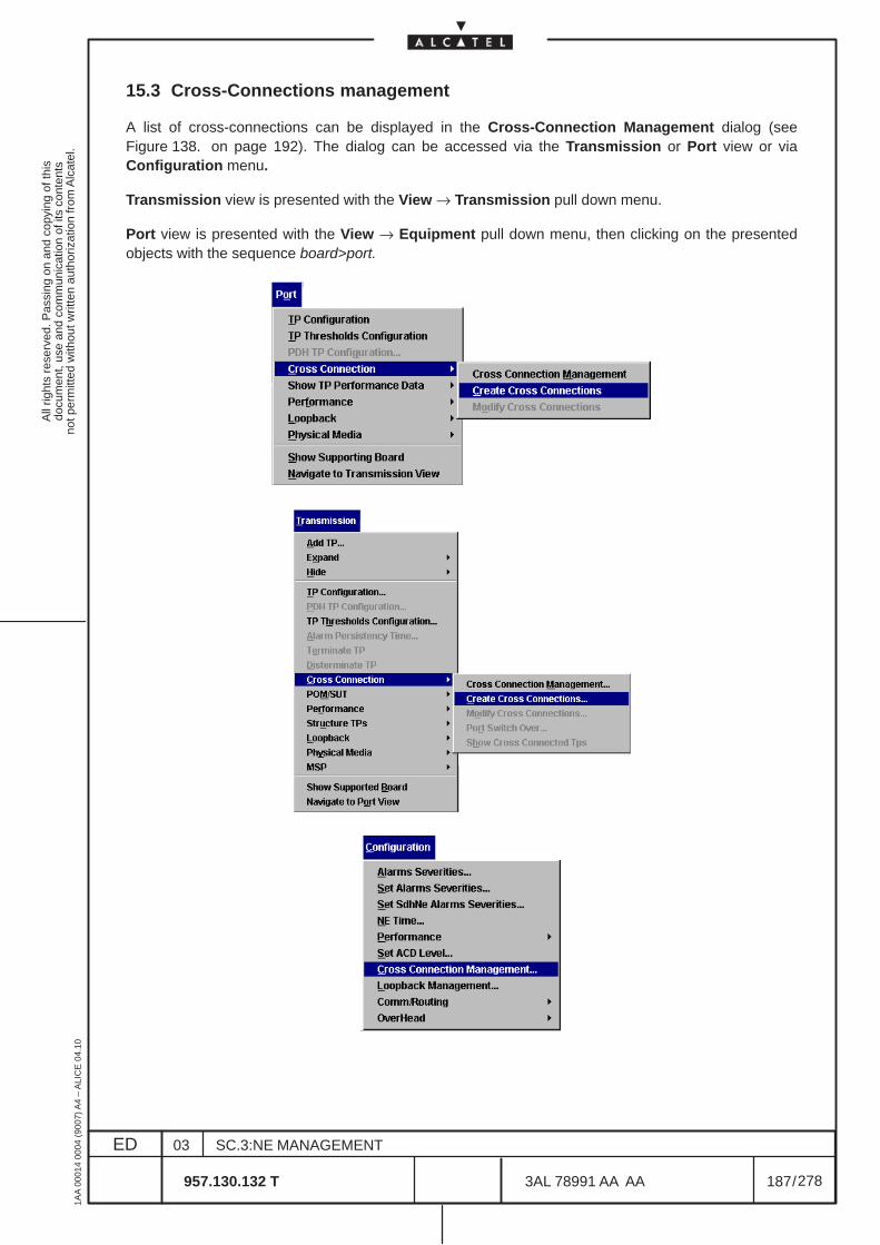
All
right
s re
serv
ed. P
assi
ng o
n an
d co
pyin
g of
this
docu
men
t, us
e an
d co
mm
unic
atio
n of
its
cont
ents
not p
erm
itted
with
out w
ritte
n au
thor
izat
ion
from
Alc
atel
.
ED
1AA
000
14 0
004
(900
7) A
4 –
ALI
CE
04.
10
187
03
957.130.132 T
SC.3:NE MANAGEMENT
/3AL 78991 AA AA
278
278
15.3 Cross-Connections management
A list of cross-connections can be displayed in the Cross-Connection Management dialog (seeFigure 138. on page 192). The dialog can be accessed via the Transmission or Port view or viaConfiguration menu.
Transmission view is presented with the View → Transmission pull down menu.
Port view is presented with the View → Equipment pull down menu, then clicking on the presentedobjects with the sequence board>port.
All
right
s re
serv
ed. P
assi
ng o
n an
d co
pyin
g of
this
docu
men
t, us
e an
d co
mm
unic
atio
n of
its
cont
ents
not p
erm
itted
with
out w
ritte
n au
thor
izat
ion
from
Alc
atel
.
ED
1AA
000
14 0
004
(900
7) A
4 –
ALI
CE
04.
10
188
03
957.130.132 T
SC.3:NE MANAGEMENT
/3AL 78991 AA AA
278
278
The Cross-Connection Management dialog is initially empty (see Figure 137. on page 190).
A list of cross-connections is displayed in the Cross-Connection Management dialog after selecting theSearch command.
There are two possibilities of displaying a list of cross-connections:
– do not enter any search criteria and press the Search button to display a list of all existingcross-connections,
– enter Search Criteria (one or more) and then press the Search button to display a selection ofcross-connections. Set Ignore for attributes not to be used as filtering criteria.
Use button Cancel Search to cancel an active search request or close the dialog.
All
right
s re
serv
ed. P
assi
ng o
n an
d co
pyin
g of
this
docu
men
t, us
e an
d co
mm
unic
atio
n of
its
cont
ents
not p
erm
itted
with
out w
ritte
n au
thor
izat
ion
from
Alc
atel
.
ED
1AA
000
14 0
004
(900
7) A
4 –
ALI
CE
04.
10
189
03
957.130.132 T
SC.3:NE MANAGEMENT
/3AL 78991 AA AA
278
278
15.3.1 Search Criteria
– Name (not supported in current release)
Number of the cross–connection (automatically assigned)
– ACD (not supported in current release)
Enter the Access Control Domain of the relevant cross-connections: E= connection made with1353SH, M= connection made with 1354RM, empty= connection made with CT.This filter option can only be used, if at least one ACD is defined on the NE and one or morecross-connections are assigned to this ACD(s).
– TypeSelect the connection type:
• Unidirectional• Bidirectional• Multipoint• Drop&Continue
– ProtectionSelect protection functionality:
• Protected• Not protected
– TP ClassSelect one of the TP types involved in the requested cross-connection.
– StateSelect the connection state:• Activated• Deactivated (not operative in current release, the connection state is always Activated)
– Prot. StateSelect the protection state (for more detailed information, refer to Chapter 9.5):• Forced to Input• Forced to Protecting• Manual Switch to Input• Manual Switch to Protecting• Auto. Switch to Input• Auto. Switch to Protecting• Lockout• Normal I• Normal P
– TP ID PrefixEnter the TP type and physical location of the port, or only the physical location at least down to boardlevel, according to the following format:r<rack#>s<subr.#>b<board#>/port#<port#>-TP (see Figure 138. on page 192)The # within brackets identifies a number.
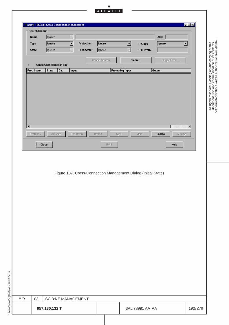
All
right
s re
serv
ed. P
assi
ng o
n an
d co
pyin
g of
this
docu
men
t, us
e an
d co
mm
unic
atio
n of
its
cont
ents
not p
erm
itted
with
out w
ritte
n au
thor
izat
ion
from
Alc
atel
.
ED
1AA
000
14 0
004
(900
7) A
4 –
ALI
CE
04.
10
190
03
957.130.132 T
SC.3:NE MANAGEMENT
/3AL 78991 AA AA
278
278
Figure 137. Cross-Connection Management Dialog (Initial State)
All
right
s re
serv
ed. P
assi
ng o
n an
d co
pyin
g of
this
docu
men
t, us
e an
d co
mm
unic
atio
n of
its
cont
ents
not p
erm
itted
with
out w
ritte
n au
thor
izat
ion
from
Alc
atel
.
ED
1AA
000
14 0
004
(900
7) A
4 –
ALI
CE
04.
10
191
03
957.130.132 T
SC.3:NE MANAGEMENT
/3AL 78991 AA AA
278
278
15.3.2 Cross-Connection List
After a successful search, a read only list of cross-connections matching the search criteria appears(see Figure 138. ). The number of matching cross-connections is displayed in the upper left corner of thelist. The list contains information concerning the following parameters for each cross-connection:
– Prot. Statedetailed switching information in the format:<protection state> <traffic ind> (<location>:<signal state>–<switch status>,[<location>:<signal state>–<switch status>])
• <protection state>Normal, Auto, Lockout, Forced or Manual.
• <traffic ind>indicates the location of current traffic:P (Protecting input) or I (Input).
• <location>indicates the location of the errored signal:P (Protecting input) or I (Input)
• <signal state>indicates the signal state: SD (Signal Degrade) or SF (Signal Failure)
• <switch status>status of the switch:c (completed) or p (pending)
Example:Auto I (P:SD-c)There has been an Automatic switch from the protecting input to the Input where the traffic iscurrently located. The reason for the automatic switch was Signal Degrade in the Protecting input.The switch was completed.
– Stateconnection state indicating whether cross-connection is A(ctivated) or D(eactivated)
– Dir.Direction-related connection type:uni(directional), bi(directional) or mp (multipoint)
– Inputsignal source; contains the TP type and physical location of the port according to the format<rack#>–<subr.#>–<board#>–<port#>,<port#>#TP (see Figure 138. on page 192)The # within brackets identifies a number.
– Protecting Inputprotecting source (for protected cross-connections only); contains the TP type and physical locationof the port according to the formatr<rack#>s<subr.#>b<board#>/port#<port#>-TP (see Figure 138. on page 192)The # within brackets identifies a number.
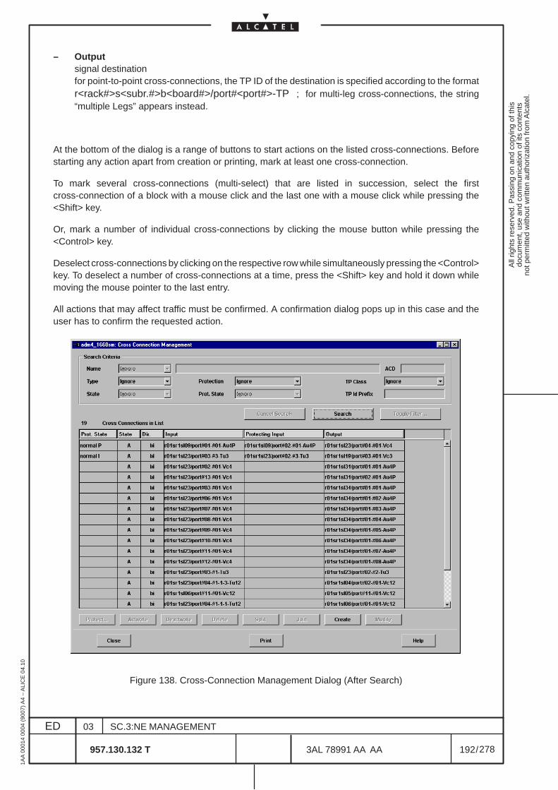
All
right
s re
serv
ed. P
assi
ng o
n an
d co
pyin
g of
this
docu
men
t, us
e an
d co
mm
unic
atio
n of
its
cont
ents
not p
erm
itted
with
out w
ritte
n au
thor
izat
ion
from
Alc
atel
.
ED
1AA
000
14 0
004
(900
7) A
4 –
ALI
CE
04.
10
192
03
957.130.132 T
SC.3:NE MANAGEMENT
/3AL 78991 AA AA
278
278
– Outputsignal destinationfor point-to-point cross-connections, the TP ID of the destination is specified according to the formatr<rack#>s<subr.#>b<board#>/port#<port#>-TP ; for multi-leg cross-connections, the string“multiple Legs” appears instead.
At the bottom of the dialog is a range of buttons to start actions on the listed cross-connections. Beforestarting any action apart from creation or printing, mark at least one cross-connection.
To mark several cross-connections (multi-select) that are listed in succession, select the firstcross-connection of a block with a mouse click and the last one with a mouse click while pressing the<Shift> key.
Or, mark a number of individual cross-connections by clicking the mouse button while pressing the<Control> key.
Deselect cross-connections by clicking on the respective row while simultaneously pressing the <Control>key. To deselect a number of cross-connections at a time, press the <Shift> key and hold it down whilemoving the mouse pointer to the last entry.
All actions that may affect traffic must be confirmed. A confirmation dialog pops up in this case and theuser has to confirm the requested action.
Figure 138. Cross-Connection Management Dialog (After Search)
All
right
s re
serv
ed. P
assi
ng o
n an
d co
pyin
g of
this
docu
men
t, us
e an
d co
mm
unic
atio
n of
its
cont
ents
not p
erm
itted
with
out w
ritte
n au
thor
izat
ion
from
Alc
atel
.
ED
1AA
000
14 0
004
(900
7) A
4 –
ALI
CE
04.
10
193
03
957.130.132 T
SC.3:NE MANAGEMENT
/3AL 78991 AA AA
278
278
15.3.3 Actions available
The following actions are available:
– Create a cross–connection (see chapter 15.4 on page 194)
The Main Cross-Connection dialog (see Figure 142. on page 201) is opened.
– Modify a Cross-Connection (see chapter 15.4 on page 194)Available if just one cross-connection is selected from the list. The Main Cross-Connection dialog(see Figure 142. on page 201) is opened.
– Activate a Cross-Connection (see chapter 15.5 on page 209)Available if at least one cross-connection is selected from the list. Not operative in current release.
– Deactivate a Cross-Connection (see chapter 15.5 on page 209)Available if at least one cross-connection is selected from the list. Not operative in current release.
– Delete a Cross-Connection (see chapter 15.5 on page 209)Available if at least one cross-connection is selected from the list.
– Split a Cross-Connection (see paragraph 15.6.1 on page 212)Available if at least one bidirectional cross connection is selected from the list.Not operative in current release.
– Join Cross-Connections (see paragraph 15.6.2 on page 212)Available if two cross connections are selected. Not operative in current release.
– Protection Switching (see chapter 15.7 on page 213)Available if exactly one protected cross-connection is selected from the list. The Protection Actionsdialog is opened.
– Print (see chapter 15.8 on page 215)Prints the filtered list of cross-connections.
The dialog has to be closed explicitly.
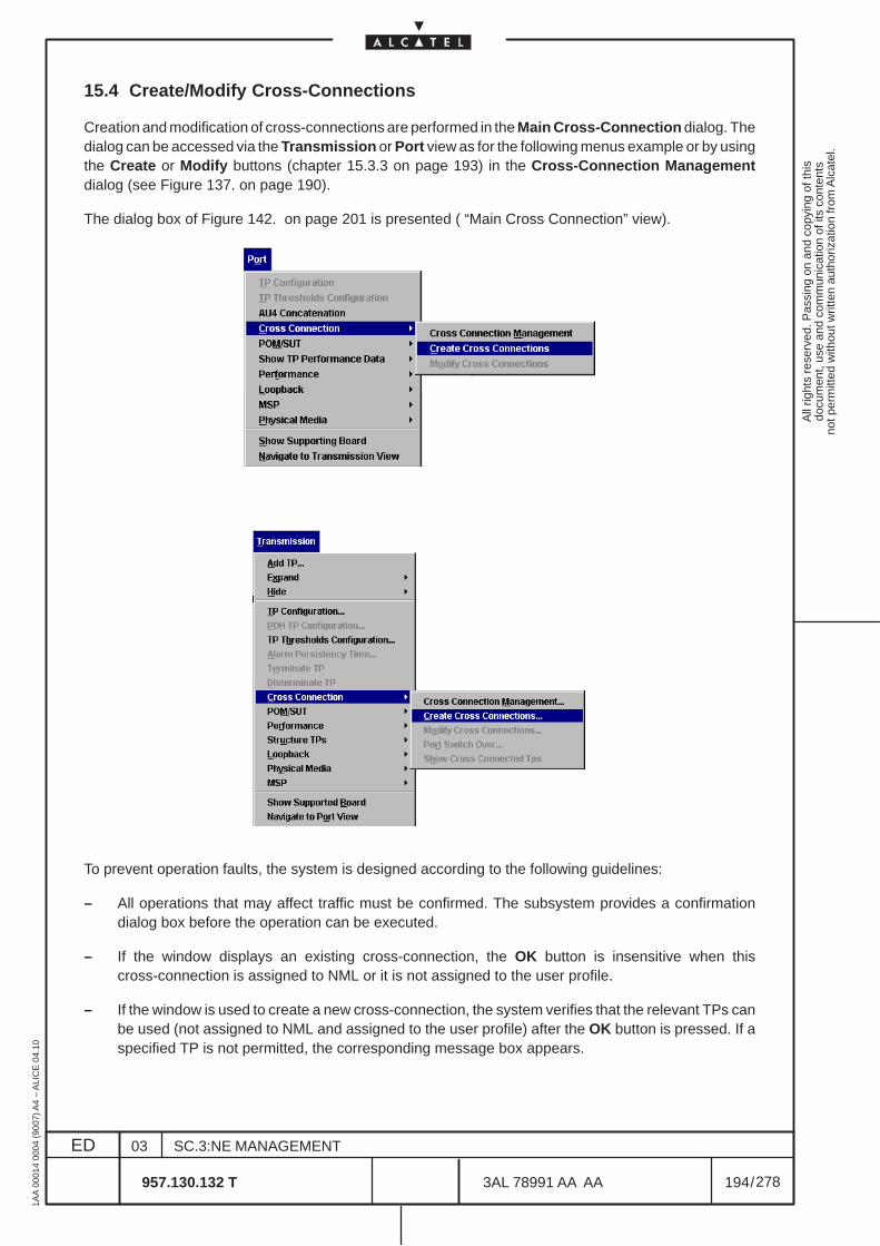
All
right
s re
serv
ed. P
assi
ng o
n an
d co
pyin
g of
this
docu
men
t, us
e an
d co
mm
unic
atio
n of
its
cont
ents
not p
erm
itted
with
out w
ritte
n au
thor
izat
ion
from
Alc
atel
.
ED
1AA
000
14 0
004
(900
7) A
4 –
ALI
CE
04.
10
194
03
957.130.132 T
SC.3:NE MANAGEMENT
/3AL 78991 AA AA
278
278
15.4 Create/Modify Cross-Connections
Creation and modification of cross-connections are performed in the Main Cross-Connection dialog. Thedialog can be accessed via the Transmission or Port view as for the following menus example or by usingthe Create or Modify buttons (chapter 15.3.3 on page 193) in the Cross-Connection Managementdialog (see Figure 137. on page 190).
The dialog box of Figure 142. on page 201 is presented ( “Main Cross Connection” view).
To prevent operation faults, the system is designed according to the following guidelines:
– All operations that may affect traffic must be confirmed. The subsystem provides a confirmationdialog box before the operation can be executed.
– If the window displays an existing cross-connection, the OK button is insensitive when thiscross-connection is assigned to NML or it is not assigned to the user profile.
– If the window is used to create a new cross-connection, the system verifies that the relevant TPs canbe used (not assigned to NML and assigned to the user profile) after the OK button is pressed. If aspecified TP is not permitted, the corresponding message box appears.
All
right
s re
serv
ed. P
assi
ng o
n an
d co
pyin
g of
this
docu
men
t, us
e an
d co
mm
unic
atio
n of
its
cont
ents
not p
erm
itted
with
out w
ritte
n au
thor
izat
ion
from
Alc
atel
.
ED
1AA
000
14 0
004
(900
7) A
4 –
ALI
CE
04.
10
195
03
957.130.132 T
SC.3:NE MANAGEMENT
/3AL 78991 AA AA
278
278
15.4.1 Cross-Connection Parameters
The “Main Cross Connection” view of Figure 142. on page 201 permits to create the cross connections.
A cross-connection is defined through a set of parameters which depend on the connection and protectiontype. Only those parameters which are permitted within the current context can be accessed. All othersare disabled (faded gray).
To create a cross-connection, one or more of those parameters must be defined according to thecross-connection type. Table 2. gives an overview about the optional and mandatory input parameters forthe various cross-connection types. Activate the relevant entry boxes first of all by clicking on them withthe mouse.
Configurable Parameters
– TypeSelect the connection type:• Unidirectional• Bidirectional• Drop&Continue
– D&C TopologySelect the direction for Drop&Continue:• Normal• Inverse
– ProtectionDefine protection state:• Protected• Not Protected
– Prot. Criteria (only available for protected connections)
Clicking on the Prot. Criteria button, Figure 139. for the Protection Criteria dialog is opened, wherethe user can display and configure the criteria for automatic protection switching.
The following criteria are always present and cannot be changed by the user:
• AU-TU-AIS (Alarm Indication Signal).
• LOP (Loss Of Pointer)
– The following switching criterion can be configured selecting the respective button:
• ExBer (Excessive Bit error rate)
This parameter are important to define the SNCP protection:
• SNCP/I: only AU–TU–AIS and LOP fixed criteria used
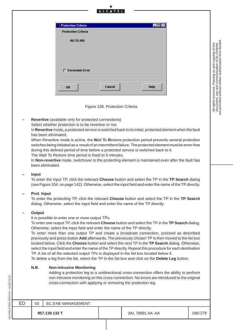
All
right
s re
serv
ed. P
assi
ng o
n an
d co
pyin
g of
this
docu
men
t, us
e an
d co
mm
unic
atio
n of
its
cont
ents
not p
erm
itted
with
out w
ritte
n au
thor
izat
ion
from
Alc
atel
.
ED
1AA
000
14 0
004
(900
7) A
4 –
ALI
CE
04.
10
196
03
957.130.132 T
SC.3:NE MANAGEMENT
/3AL 78991 AA AA
278
278
Figure 139. Protection Criteria
– Revertive (available only for protected connections)Select whether protection is to be revertive or not.In Revertive mode, a protected service is switched back to its initial, protected element when the faulthas been eliminated.When Revertive mode is active, the Wait To Restore protection period prevents several protectionswitches being initiated as a result of an intermittent failure. The protected element must be error-freeduring this defined period of time before a protected service is switched back to it.The Wait To Restore time period is fixed to 5 minutes.In Non-revertive mode, switchover to the protecting element is maintained even after the fault hasbeen eliminated.
– InputTo enter the input TP, click the relevant Choose button and select the TP in the TP Search dialog(see Figure 104. on page 142). Otherwise, select the input field and enter the name of the TP directly.
– Prot. InputTo enter the protecting TP, click the relevant Choose button and select the TP in the TP Searchdialog. Otherwise, select the input field and enter the name of the TP directly.
– OutputIt is possible to enter one or more output TPs.To enter one output TP, click the relevant Choose button and select the TP in the TP Search dialog.Otherwise, select the input field and enter the name of the TP directly.To enter more than one output TP and create a broadcast connection, proceed as describedpreviously and press button Add afterwards. The previously chosen TP is then moved to the list boxlocated below. Click the Choose button and select the next TP in the TP Search dialog. Otherwise,select the input field and enter the name of the TP directly. Repeat this procedure for each destinationTP. A list of all the selected output TPs is displayed in the list box located below it.To delete a leg from the list, select the TP in the list box and click on the Delete Leg button.
N.B. Non-intrusive MonitoringAdding a protection leg to a unidirectional cross-connection offers the ability to performnon-intrusive monitoring on this cross-connection. No errors are introduced to the originalcross-connection with applying or removing the protection leg.
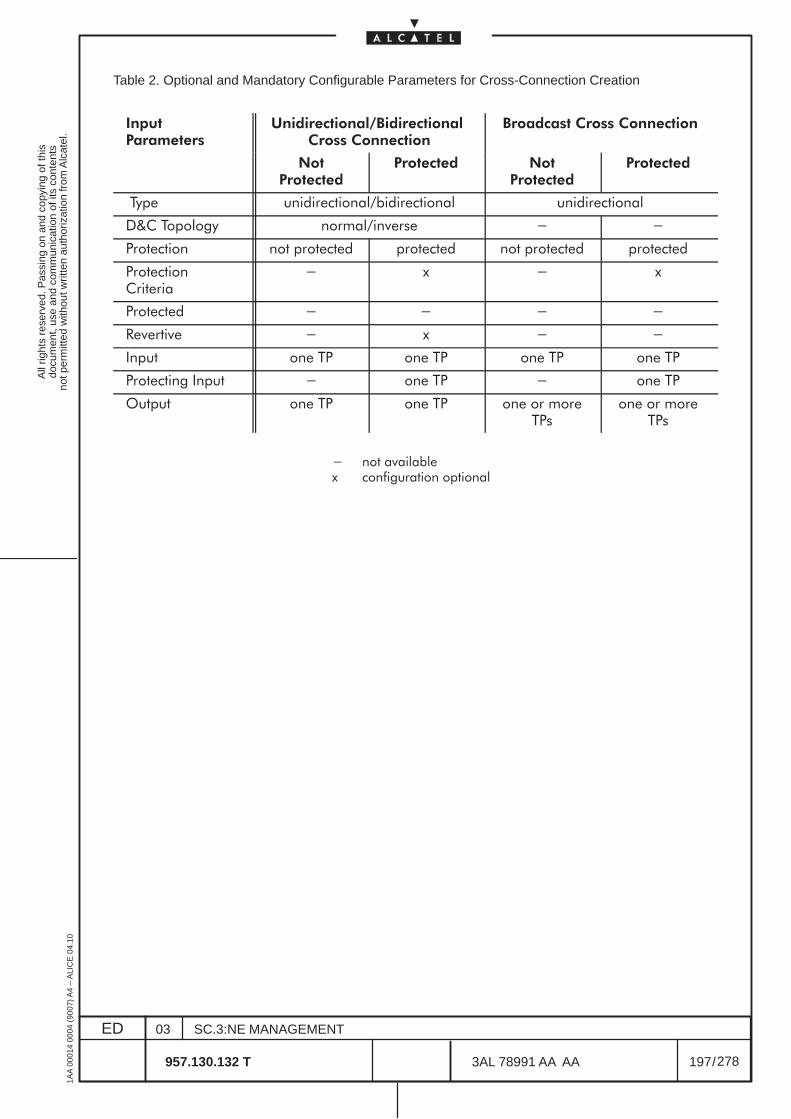
All
right
s re
serv
ed. P
assi
ng o
n an
d co
pyin
g of
this
docu
men
t, us
e an
d co
mm
unic
atio
n of
its
cont
ents
not p
erm
itted
with
out w
ritte
n au
thor
izat
ion
from
Alc
atel
.
ED
1AA
000
14 0
004
(900
7) A
4 –
ALI
CE
04.
10
197
03
957.130.132 T
SC.3:NE MANAGEMENT
/3AL 78991 AA AA
278
278
Table 2. Optional and Mandatory Configurable Parameters for Cross-Connection Creation
��� ���������
������������������������� ����� �������
��������� ����� �������
��� ��������
�������� ��� ��������
��������
���� ������������%����������� ������������
&'� ������(� ������%��)���� * *
��������� ��� ������� ������� ��� ������� �������
�����������������
* " * "
������� * * * *
+�)����)� * " * *
,���� ��� �� ��� �� ��� �� ��� ��
��������( ,���� * ��� �� * ��� ��
����� ��� �� ��� �� ��� �� �������
��� �� �������
* ��� �)�������" ����(������� ��������
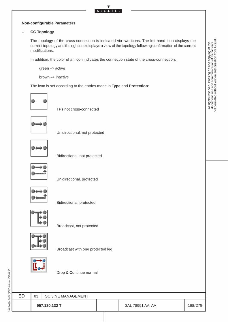
All
right
s re
serv
ed. P
assi
ng o
n an
d co
pyin
g of
this
docu
men
t, us
e an
d co
mm
unic
atio
n of
its
cont
ents
not p
erm
itted
with
out w
ritte
n au
thor
izat
ion
from
Alc
atel
.
ED
1AA
000
14 0
004
(900
7) A
4 –
ALI
CE
04.
10
198
03
957.130.132 T
SC.3:NE MANAGEMENT
/3AL 78991 AA AA
278
278
Non-configurable Parameters
– CC Topology
The topology of the cross-connection is indicated via two icons. The left-hand icon displays thecurrent topology and the right one displays a view of the topology following confirmation of the currentmodifications.
In addition, the color of an icon indicates the connection state of the cross-connection:
green –> active
brown –> inactive
The icon is set according to the entries made in Type and Protection:
TPs not cross-connected
Unidirectional, not protected
Bidirectional, not protected
Unidirectional, protected
Bidirectional, protected
Broadcast, not protected
Broadcast with one protected leg
Drop & Continue normal
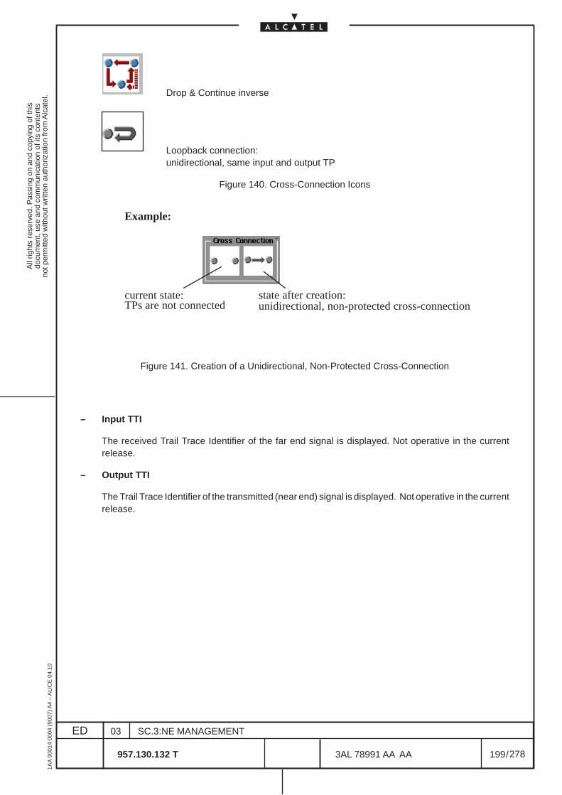
All
right
s re
serv
ed. P
assi
ng o
n an
d co
pyin
g of
this
docu
men
t, us
e an
d co
mm
unic
atio
n of
its
cont
ents
not p
erm
itted
with
out w
ritte
n au
thor
izat
ion
from
Alc
atel
.
ED
1AA
000
14 0
004
(900
7) A
4 –
ALI
CE
04.
10
199
03
957.130.132 T
SC.3:NE MANAGEMENT
/3AL 78991 AA AA
278
278
Drop & Continue inverse
Loopback connection:unidirectional, same input and output TP
Figure 140. Cross-Connection Icons
current state:TPs are not connected
state after creation:unidirectional, non-protected cross-connection
Example:
Figure 141. Creation of a Unidirectional, Non-Protected Cross-Connection
– Input TTI
The received Trail Trace Identifier of the far end signal is displayed. Not operative in the currentrelease.
– Output TTI
The Trail Trace Identifier of the transmitted (near end) signal is displayed. Not operative in the currentrelease.
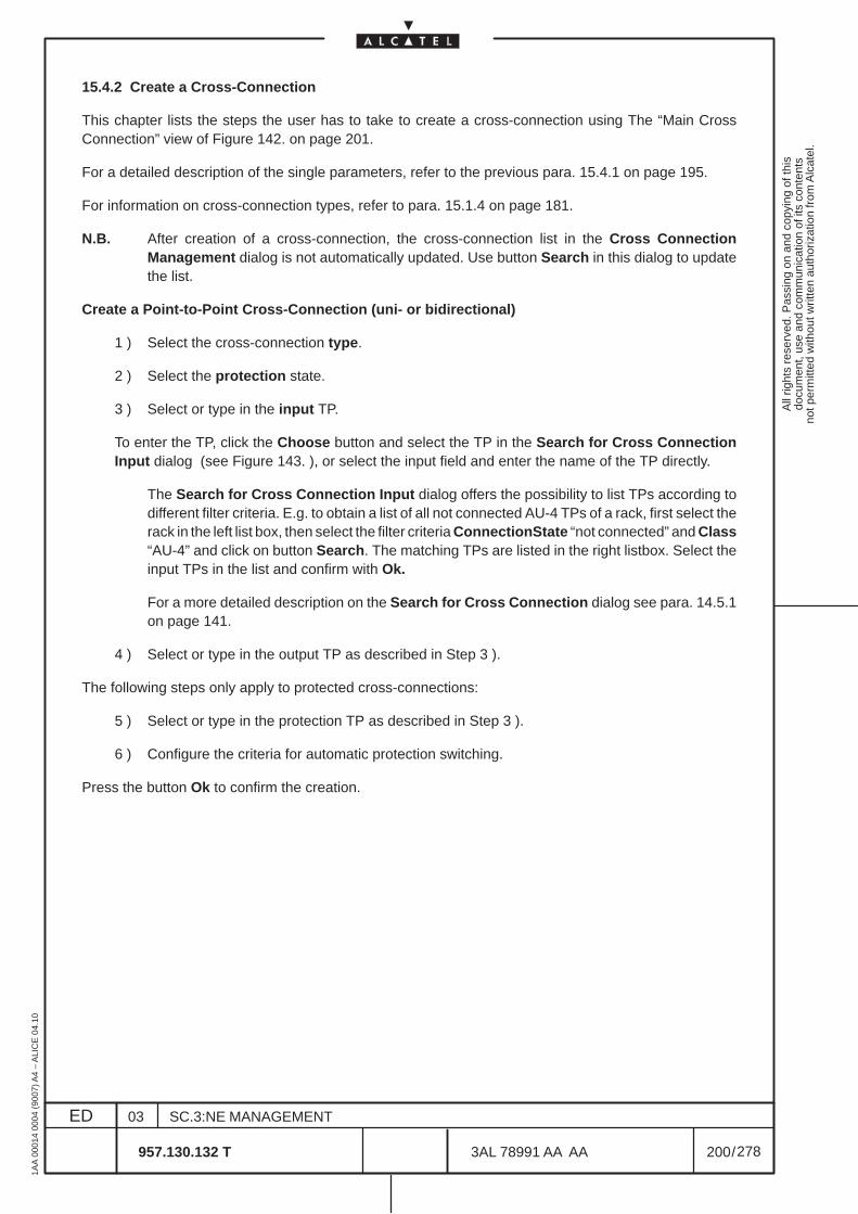
All
right
s re
serv
ed. P
assi
ng o
n an
d co
pyin
g of
this
docu
men
t, us
e an
d co
mm
unic
atio
n of
its
cont
ents
not p
erm
itted
with
out w
ritte
n au
thor
izat
ion
from
Alc
atel
.
ED
1AA
000
14 0
004
(900
7) A
4 –
ALI
CE
04.
10
200
03
957.130.132 T
SC.3:NE MANAGEMENT
/3AL 78991 AA AA
278
278
15.4.2 Create a Cross-Connection
This chapter lists the steps the user has to take to create a cross-connection using The “Main CrossConnection” view of Figure 142. on page 201.
For a detailed description of the single parameters, refer to the previous para. 15.4.1 on page 195.
For information on cross-connection types, refer to para. 15.1.4 on page 181.
N.B. After creation of a cross-connection, the cross-connection list in the Cross ConnectionManagement dialog is not automatically updated. Use button Search in this dialog to updatethe list.
Create a Point-to-Point Cross-Connection (uni- or bidirectional)
1 ) Select the cross-connection type.
2 ) Select the protection state.
3 ) Select or type in the input TP.
To enter the TP, click the Choose button and select the TP in the Search for Cross ConnectionInput dialog (see Figure 143. ), or select the input field and enter the name of the TP directly.
The Search for Cross Connection Input dialog offers the possibility to list TPs according todifferent filter criteria. E.g. to obtain a list of all not connected AU-4 TPs of a rack, first select therack in the left list box, then select the filter criteria ConnectionState “not connected” and Class“AU-4” and click on button Search. The matching TPs are listed in the right listbox. Select theinput TPs in the list and confirm with Ok.
For a more detailed description on the Search for Cross Connection dialog see para. 14.5.1on page 141.
4 ) Select or type in the output TP as described in Step 3 ).
The following steps only apply to protected cross-connections:
5 ) Select or type in the protection TP as described in Step 3 ).
6 ) Configure the criteria for automatic protection switching.
Press the button Ok to confirm the creation.
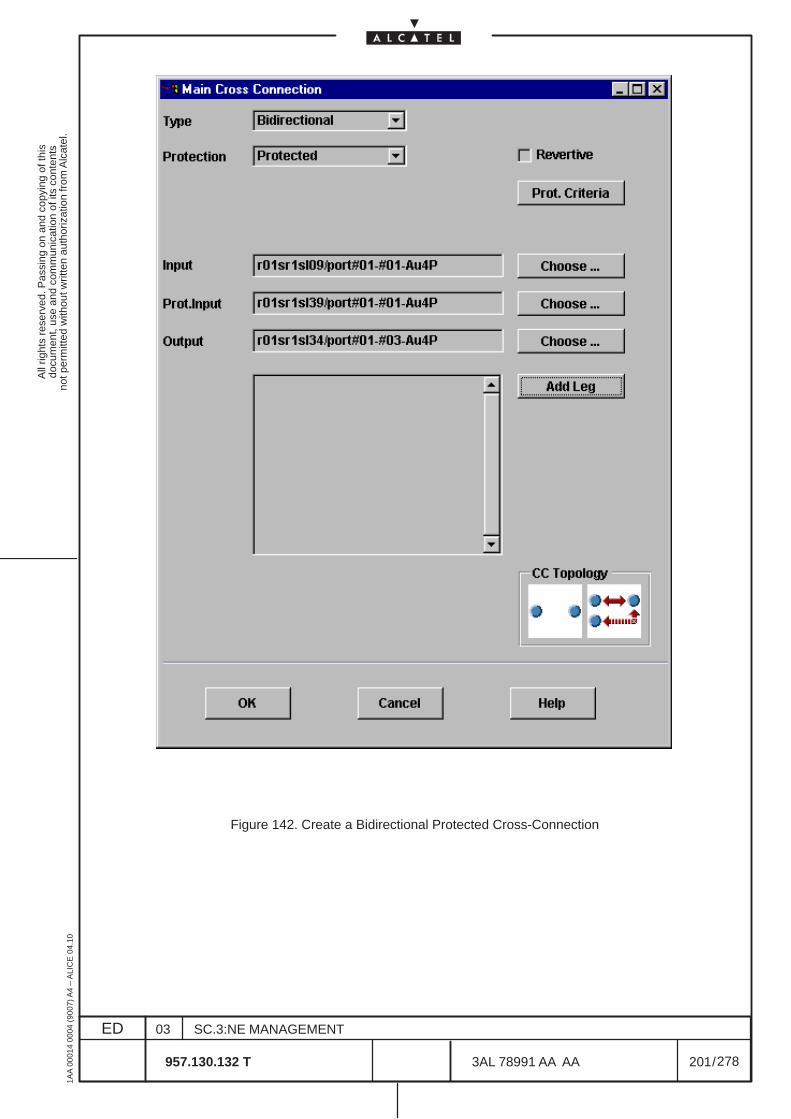
All
right
s re
serv
ed. P
assi
ng o
n an
d co
pyin
g of
this
docu
men
t, us
e an
d co
mm
unic
atio
n of
its
cont
ents
not p
erm
itted
with
out w
ritte
n au
thor
izat
ion
from
Alc
atel
.
ED
1AA
000
14 0
004
(900
7) A
4 –
ALI
CE
04.
10
201
03
957.130.132 T
SC.3:NE MANAGEMENT
/3AL 78991 AA AA
278
278
Figure 142. Create a Bidirectional Protected Cross-Connection
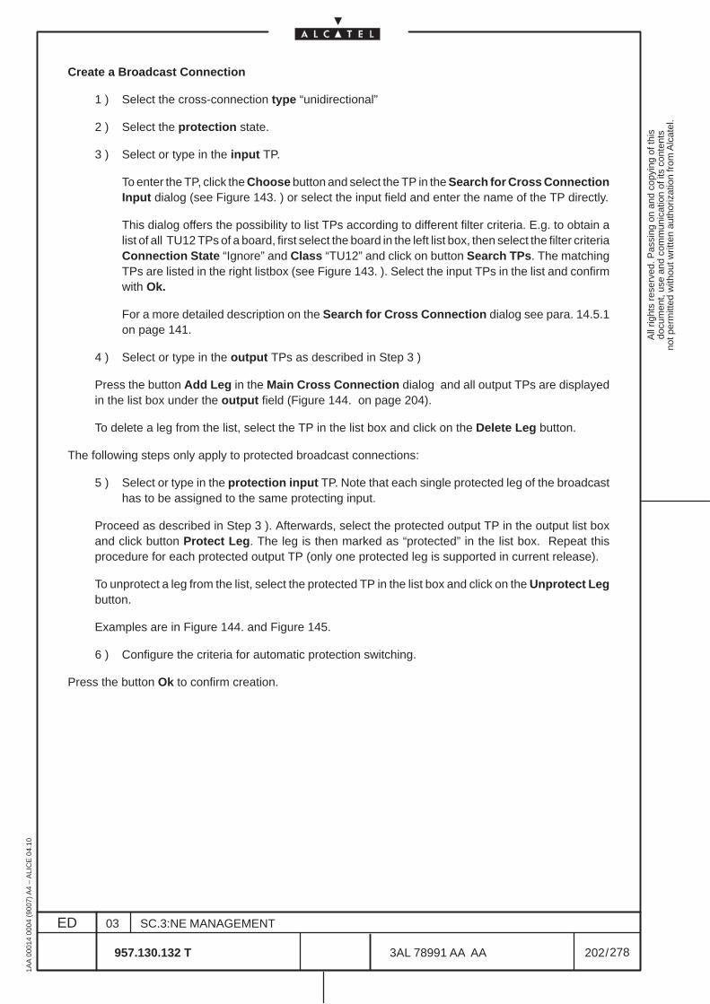
All
right
s re
serv
ed. P
assi
ng o
n an
d co
pyin
g of
this
docu
men
t, us
e an
d co
mm
unic
atio
n of
its
cont
ents
not p
erm
itted
with
out w
ritte
n au
thor
izat
ion
from
Alc
atel
.
ED
1AA
000
14 0
004
(900
7) A
4 –
ALI
CE
04.
10
202
03
957.130.132 T
SC.3:NE MANAGEMENT
/3AL 78991 AA AA
278
278
Create a Broadcast Connection
1 ) Select the cross-connection type “unidirectional”
2 ) Select the protection state.
3 ) Select or type in the input TP.
To enter the TP, click the Choose button and select the TP in the Search for Cross ConnectionInput dialog (see Figure 143. ) or select the input field and enter the name of the TP directly.
This dialog offers the possibility to list TPs according to different filter criteria. E.g. to obtain alist of all TU12 TPs of a board, first select the board in the left list box, then select the filter criteriaConnection State “Ignore” and Class “TU12” and click on button Search TPs. The matchingTPs are listed in the right listbox (see Figure 143. ). Select the input TPs in the list and confirmwith Ok.
For a more detailed description on the Search for Cross Connection dialog see para. 14.5.1on page 141.
4 ) Select or type in the output TPs as described in Step 3 )
Press the button Add Leg in the Main Cross Connection dialog and all output TPs are displayedin the list box under the output field (Figure 144. on page 204).
To delete a leg from the list, select the TP in the list box and click on the Delete Leg button.
The following steps only apply to protected broadcast connections:
5 ) Select or type in the protection input TP. Note that each single protected leg of the broadcasthas to be assigned to the same protecting input.
Proceed as described in Step 3 ). Afterwards, select the protected output TP in the output list boxand click button Protect Leg. The leg is then marked as “protected” in the list box. Repeat thisprocedure for each protected output TP (only one protected leg is supported in current release).
To unprotect a leg from the list, select the protected TP in the list box and click on the Unprotect Legbutton.
Examples are in Figure 144. and Figure 145.
6 ) Configure the criteria for automatic protection switching.
Press the button Ok to confirm creation.
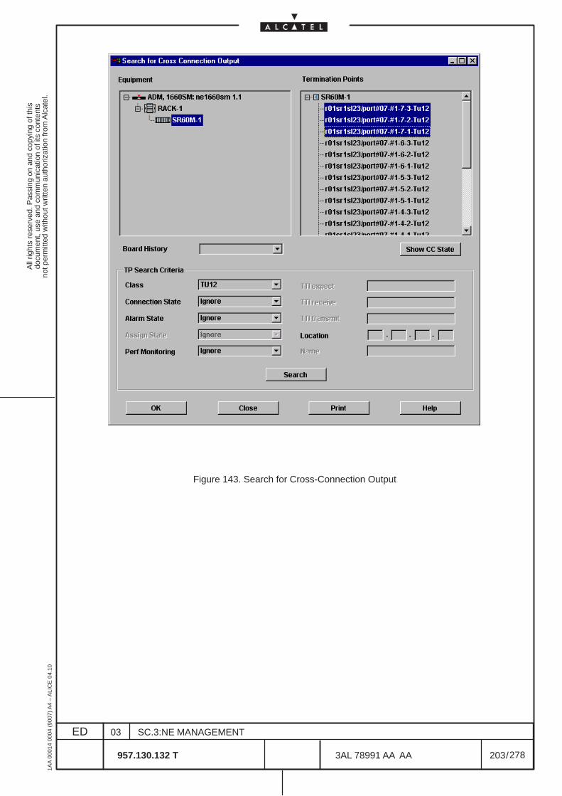
All
right
s re
serv
ed. P
assi
ng o
n an
d co
pyin
g of
this
docu
men
t, us
e an
d co
mm
unic
atio
n of
its
cont
ents
not p
erm
itted
with
out w
ritte
n au
thor
izat
ion
from
Alc
atel
.
ED
1AA
000
14 0
004
(900
7) A
4 –
ALI
CE
04.
10
203
03
957.130.132 T
SC.3:NE MANAGEMENT
/3AL 78991 AA AA
278
278
Figure 143. Search for Cross-Connection Output
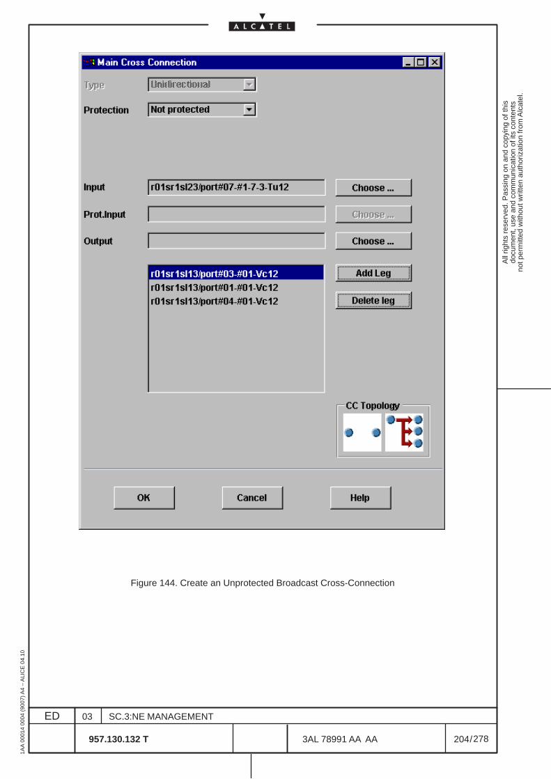
All
right
s re
serv
ed. P
assi
ng o
n an
d co
pyin
g of
this
docu
men
t, us
e an
d co
mm
unic
atio
n of
its
cont
ents
not p
erm
itted
with
out w
ritte
n au
thor
izat
ion
from
Alc
atel
.
ED
1AA
000
14 0
004
(900
7) A
4 –
ALI
CE
04.
10
204
03
957.130.132 T
SC.3:NE MANAGEMENT
/3AL 78991 AA AA
278
278
Figure 144. Create an Unprotected Broadcast Cross-Connection
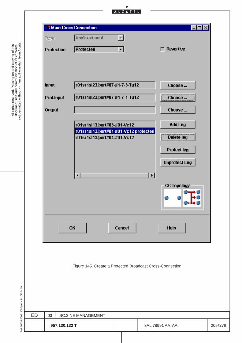
All
right
s re
serv
ed. P
assi
ng o
n an
d co
pyin
g of
this
docu
men
t, us
e an
d co
mm
unic
atio
n of
its
cont
ents
not p
erm
itted
with
out w
ritte
n au
thor
izat
ion
from
Alc
atel
.
ED
1AA
000
14 0
004
(900
7) A
4 –
ALI
CE
04.
10
205
03
957.130.132 T
SC.3:NE MANAGEMENT
/3AL 78991 AA AA
278
278
Figure 145. Create a Protected Broadcast Cross-Connection
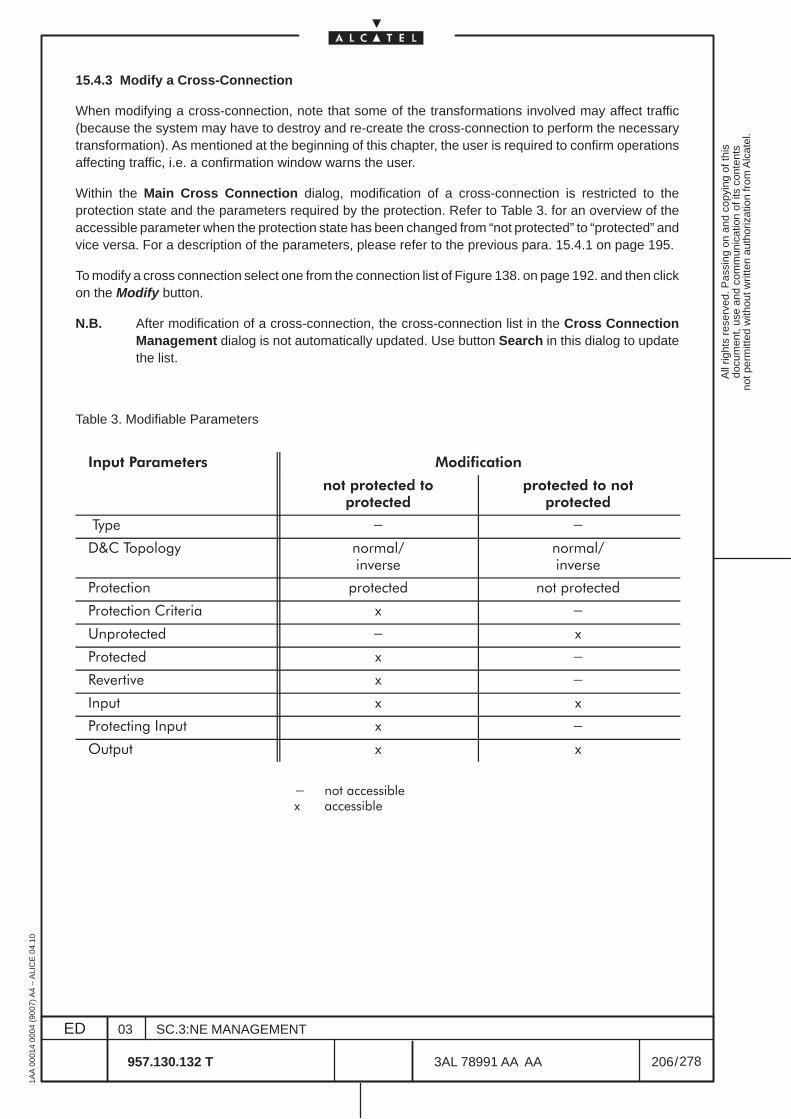
All
right
s re
serv
ed. P
assi
ng o
n an
d co
pyin
g of
this
docu
men
t, us
e an
d co
mm
unic
atio
n of
its
cont
ents
not p
erm
itted
with
out w
ritte
n au
thor
izat
ion
from
Alc
atel
.
ED
1AA
000
14 0
004
(900
7) A
4 –
ALI
CE
04.
10
206
03
957.130.132 T
SC.3:NE MANAGEMENT
/3AL 78991 AA AA
278
278
15.4.3 Modify a Cross-Connection
When modifying a cross-connection, note that some of the transformations involved may affect traffic(because the system may have to destroy and re-create the cross-connection to perform the necessarytransformation). As mentioned at the beginning of this chapter, the user is required to confirm operationsaffecting traffic, i.e. a confirmation window warns the user.
Within the Main Cross Connection dialog, modification of a cross-connection is restricted to theprotection state and the parameters required by the protection. Refer to Table 3. for an overview of theaccessible parameter when the protection state has been changed from “not protected” to “protected” andvice versa. For a description of the parameters, please refer to the previous para. 15.4.1 on page 195.
To modify a cross connection select one from the connection list of Figure 138. on page 192. and then clickon the Modify button.
N.B. After modification of a cross-connection, the cross-connection list in the Cross ConnectionManagement dialog is not automatically updated. Use button Search in this dialog to updatethe list.
Table 3. Modifiable Parameters
��� ��������� �����������
�� �������� ����������
�������� �� ����������
���� * *
&'� ������(� ������%��)����
������%��)����
��������� ������� ��� �������
��������� �������� " *
��������� * "
������� " *
+�)����)� " *
,���� " "
��������( ,���� " *
����� " "
* ��� ��������" ��������
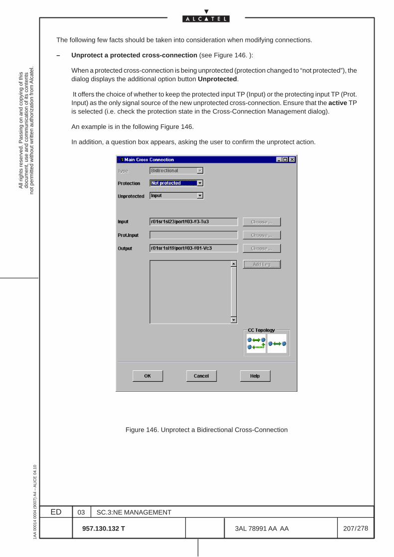
All
right
s re
serv
ed. P
assi
ng o
n an
d co
pyin
g of
this
docu
men
t, us
e an
d co
mm
unic
atio
n of
its
cont
ents
not p
erm
itted
with
out w
ritte
n au
thor
izat
ion
from
Alc
atel
.
ED
1AA
000
14 0
004
(900
7) A
4 –
ALI
CE
04.
10
207
03
957.130.132 T
SC.3:NE MANAGEMENT
/3AL 78991 AA AA
278
278
The following few facts should be taken into consideration when modifying connections.
– Unprotect a protected cross-connection (see Figure 146. ):
When a protected cross-connection is being unprotected (protection changed to “not protected”), thedialog displays the additional option button Unprotected.
It offers the choice of whether to keep the protected input TP (Input) or the protecting input TP (Prot.Input) as the only signal source of the new unprotected cross-connection. Ensure that the active TPis selected (i.e. check the protection state in the Cross-Connection Management dialog).
An example is in the following Figure 146.
In addition, a question box appears, asking the user to confirm the unprotect action.
Figure 146. Unprotect a Bidirectional Cross-Connection
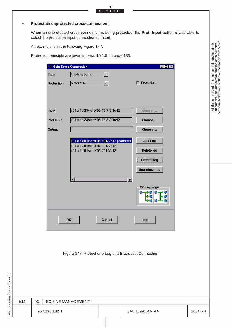
All
right
s re
serv
ed. P
assi
ng o
n an
d co
pyin
g of
this
docu
men
t, us
e an
d co
mm
unic
atio
n of
its
cont
ents
not p
erm
itted
with
out w
ritte
n au
thor
izat
ion
from
Alc
atel
.
ED
1AA
000
14 0
004
(900
7) A
4 –
ALI
CE
04.
10
208
03
957.130.132 T
SC.3:NE MANAGEMENT
/3AL 78991 AA AA
278
278
– Protect an unprotected cross-connection:
When an unprotected cross-connection is being protected, the Prot. Input button is available toselect the protection input connection to insert.
An example is in the following Figure 147.
Protection principle are given in para. 15.1.5 on page 183.
Figure 147. Protect one Leg of a Broadcast Connection
All
right
s re
serv
ed. P
assi
ng o
n an
d co
pyin
g of
this
docu
men
t, us
e an
d co
mm
unic
atio
n of
its
cont
ents
not p
erm
itted
with
out w
ritte
n au
thor
izat
ion
from
Alc
atel
.
ED
1AA
000
14 0
004
(900
7) A
4 –
ALI
CE
04.
10
209
03
957.130.132 T
SC.3:NE MANAGEMENT
/3AL 78991 AA AA
278
278
15.5 Activate/Deactivate/Delete Cross-Connections
15.5.1 Activate a Cross-Connection
Not supported in current release.
The Cross Connection Management dialog provides the possibility of displaying a selection of existingcross-connections (see Chapter 15.3 on page 187). The connection state (Act = A or D) is indicated in thisconnection list.
To activate a cross-connection, select one from the connection list (see Figure 138. ) and then click on theActivate button to initiate the process. A confirmation box appears in which to confirm the state changerequest. The connection in the list is automatically updated to indicate the new connection state (Act = A).
If the set of cross-connections selected from the list includes both activated and deactivatedcross-connections, clicking the Activate button only initiates actions on the deactivatedcross-connections which were selected.
15.5.2 Deactivate a Cross-Connection
Not supported in current release.
After creation, a cross-connection is automatically in an active state. To deactivate a cross-connection,select one from the connection list (see Figure 138. ) and then click on the Deactivate button to initiatethe process. A confirmation box appears in which to confirm the state change request. The connectionin the list is automatically updated to indicate the new connection state (Act = D).
If the set of cross-connections selected from the list includes both activated and deactivatedcross-connections, clicking the Deactivate button only initiates actions on the activatedcross-connections which were selected.
15.5.3 Delete a Cross-Connection
Only deactivated cross-connections should be deleted. However, deletion of active cross-connections ispossible.
To delete a cross-connection, select the corresponding connection from the list and click on the Deletebutton. To prevent operation errors, the user must confirm the deletion request.
The deleted cross-connection automatically disappears from the connection list when the operation issuccessful.
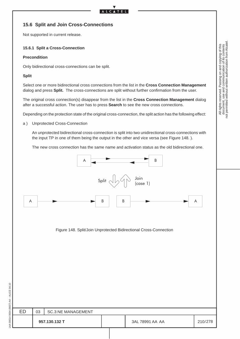
All
right
s re
serv
ed. P
assi
ng o
n an
d co
pyin
g of
this
docu
men
t, us
e an
d co
mm
unic
atio
n of
its
cont
ents
not p
erm
itted
with
out w
ritte
n au
thor
izat
ion
from
Alc
atel
.
ED
1AA
000
14 0
004
(900
7) A
4 –
ALI
CE
04.
10
210
03
957.130.132 T
SC.3:NE MANAGEMENT
/3AL 78991 AA AA
278
278
15.6 Split and Join Cross-Connections
Not supported in current release.
15.6.1 Split a Cross-Connection
Precondition
Only bidirectional cross-connections can be split.
Split
Select one or more bidirectional cross connections from the list in the Cross Connection Managementdialog and press Split. The cross-connections are split without further confirmation from the user.
The original cross connection(s) disappear from the list in the Cross Connection Management dialogafter a successful action. The user has to press Search to see the new cross connections.
Depending on the protection state of the original cross-connection, the split action has the following effect:
a ) Unprotected Cross-Connection
An unprotected bidirectional cross-connection is split into two unidirectional cross-connections withthe input TP in one of them being the output in the other and vice versa (see Figure 148. ).
The new cross connection has the same name and activation status as the old bidirectional one.
ÀÀÀÀÀÀ
ÀÀÀÀÀÀ
� �
ÀÀÀÀÀÀÀÀÀ
ÀÀÀÀÀÀÀÀÀÀÀÀ
� �ÀÀÀÀÀÀÀÀÀ
ÀÀÀÀÀÀÀÀÀÀÀÀ
� �
�����-���.��� /0
Figure 148. Split/Join Unprotected Bidirectional Cross-Connection
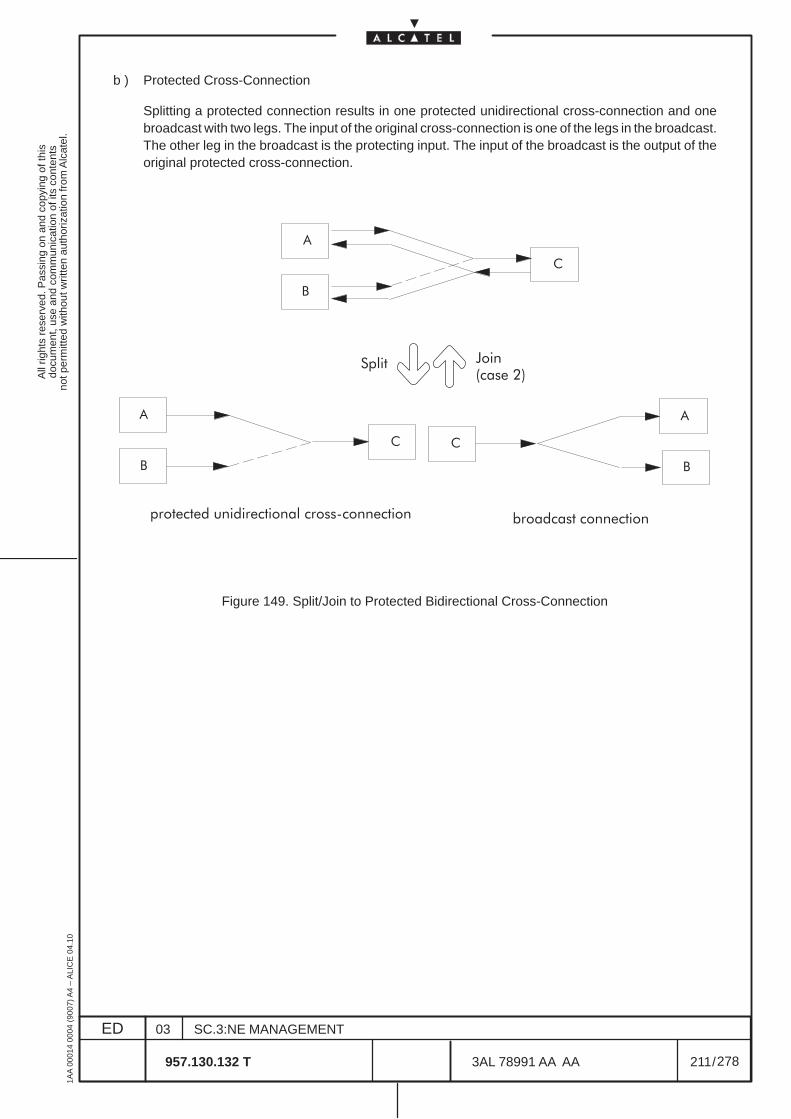
All
right
s re
serv
ed. P
assi
ng o
n an
d co
pyin
g of
this
docu
men
t, us
e an
d co
mm
unic
atio
n of
its
cont
ents
not p
erm
itted
with
out w
ritte
n au
thor
izat
ion
from
Alc
atel
.
ED
1AA
000
14 0
004
(900
7) A
4 –
ALI
CE
04.
10
211
03
957.130.132 T
SC.3:NE MANAGEMENT
/3AL 78991 AA AA
278
278
b ) Protected Cross-Connection
Splitting a protected connection results in one protected unidirectional cross-connection and onebroadcast with two legs. The input of the original cross-connection is one of the legs in the broadcast.The other leg in the broadcast is the protecting input. The input of the broadcast is the output of theoriginal protected cross-connection.
ÈÈÈÈÈÈÈÈÈÈÈÈÈÈÈÈÈÈÈÈÈÈÈÈ
ÈÈÈÈÈÈÈÈ
�
�
�
ÈÈÈÈÈÈÈÈÈÈÈÈÈÈÈÈÈÈÈÈ
ÈÈÈÈÈÈÈÈÈ
�
�
�
ÈÈÈÈÈÈÈÈÈÈÈÈÈÈÈ
ÈÈÈÈÈÈÈÈÈÈÈÈ
�
�
�
�����
������� ������������ ������������� ������� ��������
-���.��� 10
Figure 149. Split/Join to Protected Bidirectional Cross-Connection

All
right
s re
serv
ed. P
assi
ng o
n an
d co
pyin
g of
this
docu
men
t, us
e an
d co
mm
unic
atio
n of
its
cont
ents
not p
erm
itted
with
out w
ritte
n au
thor
izat
ion
from
Alc
atel
.
ED
1AA
000
14 0
004
(900
7) A
4 –
ALI
CE
04.
10
212
03
957.130.132 T
SC.3:NE MANAGEMENT
/3AL 78991 AA AA
278
278
15.6.2 Join Two Cross-Connections
Precondition
Two cross-connections can be joined if they match the following characteristics:
– The connections are either
1 ) both unprotected, unidirectional and the input is the output of the other one, or
2 ) one of them is protected and unidirectional, and the other one a broadcast with two legs.Restriction: the input of the broadcast connection has to be the output of the protectedconnection and the legs of the broadcast match the input and the protection input of theunidirectional connection, also refer to Chapter Split a Cross-Connection, effect b).
– Both cross-connections have the same connection state (activated or deactivated).
– Both cross-connections have the operational state “enabled”, i.e. they are listed in black color in theCross Connection Management dialog.
Join
Select exactly two cross connections in the Cross Connection Management dialog and press the Joinbutton. The cross-connections are joined without further confirmation from the user.
The original cross connection(s) disappear from the list in the Cross Connection Management dialogafter a successful action. Press Search to see the new cross-connections in the list.
The result is either a bidirectional (case 1, see Figure 148. ) or a protected bidirectional (case 2, seeFigure 149. ) cross-connection.
If the original cross-connections have different names, the new name is a concatenation of the names ofboth of them.

All
right
s re
serv
ed. P
assi
ng o
n an
d co
pyin
g of
this
docu
men
t, us
e an
d co
mm
unic
atio
n of
its
cont
ents
not p
erm
itted
with
out w
ritte
n au
thor
izat
ion
from
Alc
atel
.
ED
1AA
000
14 0
004
(900
7) A
4 –
ALI
CE
04.
10
213
03
957.130.132 T
SC.3:NE MANAGEMENT
/3AL 78991 AA AA
278
278
15.7 Protection Switching
The Protection Actions dialog is displayed after clicking on the Protection button in the CrossConnection Management dialog (see Figure 138. ).
Users can only switch protection on cross-connections belonging to them and not assigned to the NML.A second condition is that protection is enabled for the cross-connection concerned (protection parameteris set to “protected”).
The three protection actions Force, Lock Out and Manual Switch belong to different levels, wherebyLock has the highest priority and Manual Switch the lowest.
Note that a protection state can only be changed within the same or from a higher priority level, e.g. ForceTo Protecting can be reverted with Release but not with Manual Switch To Input.
Figure 150. Protection Actions Dialog
The dialog window enables the user to perform protection- related operations on protectedcross-connections. These are:
– Force to Input (not operative in current release)
The cross-connection is switched to the protected input regardless of signal quality. Automaticprotection is disabled.
– Force to Protecting (Input)
The cross-connection is switched to the protecting input regardless of signal quality. Automaticprotection is disabled.
– Release Force
Forced switching is disabled and automatic protection switching re-enabled.
All
right
s re
serv
ed. P
assi
ng o
n an
d co
pyin
g of
this
docu
men
t, us
e an
d co
mm
unic
atio
n of
its
cont
ents
not p
erm
itted
with
out w
ritte
n au
thor
izat
ion
from
Alc
atel
.
ED
1AA
000
14 0
004
(900
7) A
4 –
ALI
CE
04.
10
214
03
957.130.132 T
SC.3:NE MANAGEMENT
/3AL 78991 AA AA
278
278
– Manual Switch to Input (not operative in current release)
The user can switch over to the protected input manually. Switching over is not executed if the signalquality on the protected path is worse than on the protecting path.
– Manual Switch to Protecting Input (not operative in current release)
The user can switch over to the protecting input manually. Switching over is not executed if the signalquality on the protecting path is worse than on the protected path.
– Release Manual Switch (not operative in current release)
A manual switch is disabled and automatic protection switching re-enabled.
– Lock Out to Invoke
The connection path is locked for protection switching, i.e. neither forced nor manual switching canbe performed.
– Release Lock
The protection lock is disabled.
N.B. All the operations listed are context-dependent and are enabled or disabled (“grayed”)accordingly.
After completion of protection switching, the list entry in the Cross Connection Management dialog isupdated automatically.
After clicking on an action button and completing the action initiated, the dialog disappears automatically.
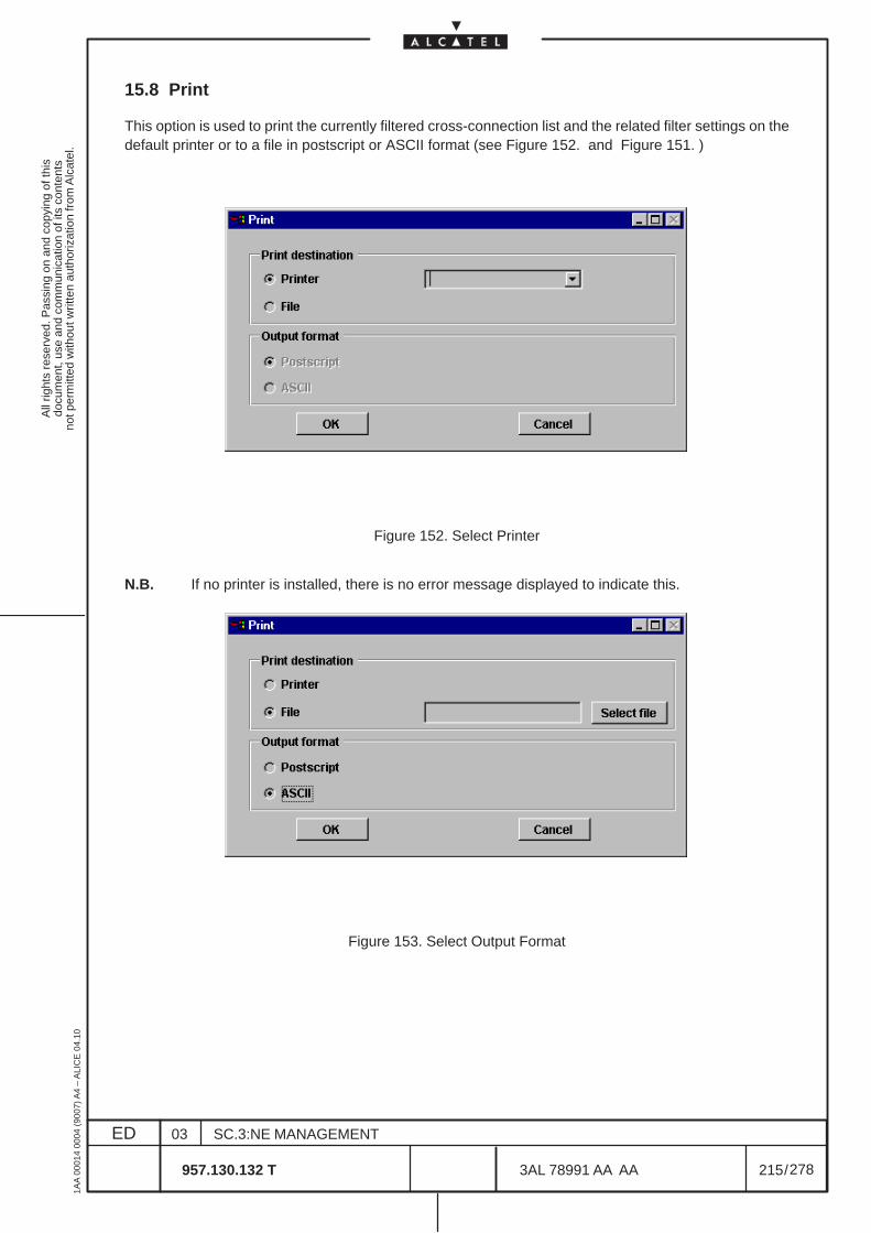
All
right
s re
serv
ed. P
assi
ng o
n an
d co
pyin
g of
this
docu
men
t, us
e an
d co
mm
unic
atio
n of
its
cont
ents
not p
erm
itted
with
out w
ritte
n au
thor
izat
ion
from
Alc
atel
.
ED
1AA
000
14 0
004
(900
7) A
4 –
ALI
CE
04.
10
215
03
957.130.132 T
SC.3:NE MANAGEMENT
/3AL 78991 AA AA
278
278
15.8 Print
This option is used to print the currently filtered cross-connection list and the related filter settings on thedefault printer or to a file in postscript or ASCII format (see Figure 152. and Figure 151. )
Figure 152. Select Printer
N.B. If no printer is installed, there is no error message displayed to indicate this.
Figure 153. Select Output Format
All
right
s re
serv
ed. P
assi
ng o
n an
d co
pyin
g of
this
docu
men
t, us
e an
d co
mm
unic
atio
n of
its
cont
ents
not p
erm
itted
with
out w
ritte
n au
thor
izat
ion
from
Alc
atel
.
ED
1AA
000
14 0
004
(900
7) A
4 –
ALI
CE
04.
10
216
03
957.130.132 T
SC.3:NE MANAGEMENT
/3AL 78991 AA AA
278
278
15.9 Port Switch Over
Not supported in current release.
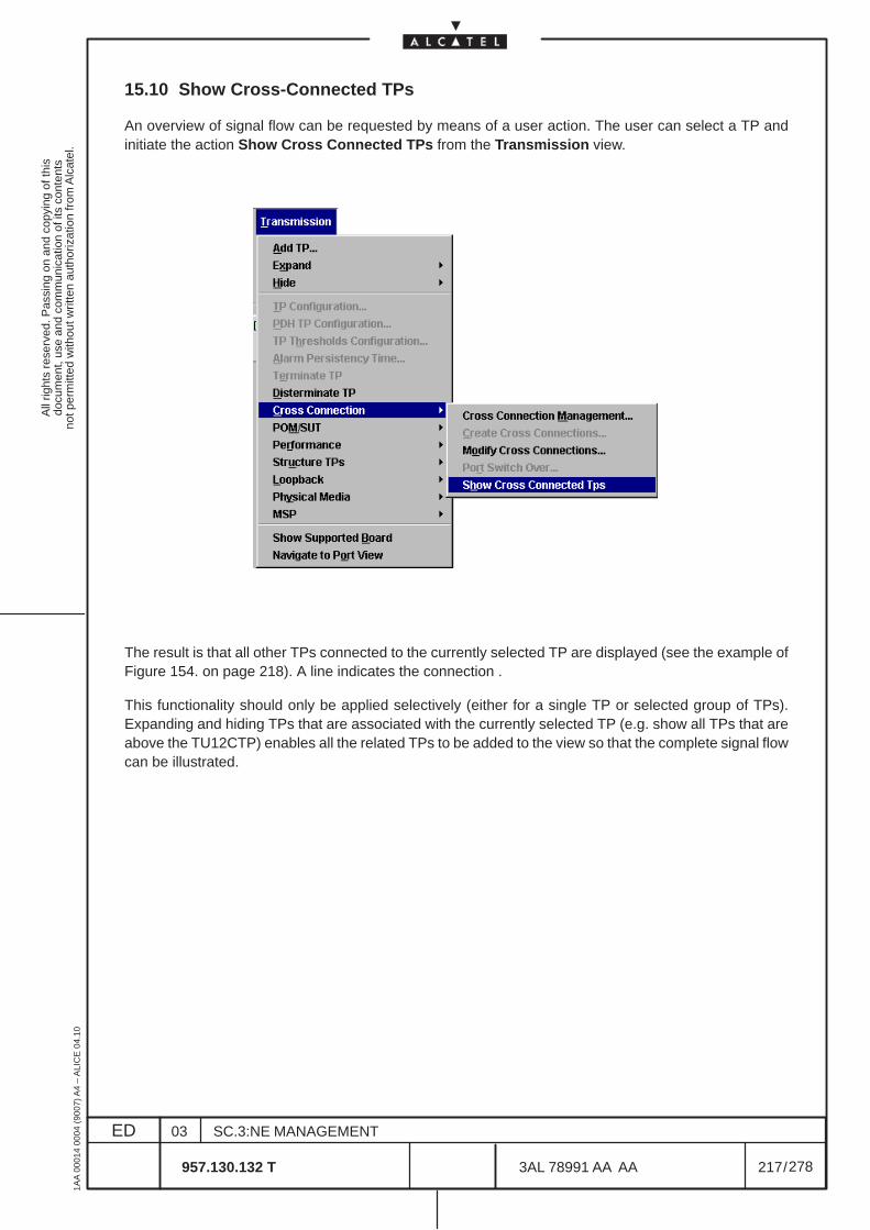
All
right
s re
serv
ed. P
assi
ng o
n an
d co
pyin
g of
this
docu
men
t, us
e an
d co
mm
unic
atio
n of
its
cont
ents
not p
erm
itted
with
out w
ritte
n au
thor
izat
ion
from
Alc
atel
.
ED
1AA
000
14 0
004
(900
7) A
4 –
ALI
CE
04.
10
217
03
957.130.132 T
SC.3:NE MANAGEMENT
/3AL 78991 AA AA
278
278
15.10 Show Cross-Connected TPs
An overview of signal flow can be requested by means of a user action. The user can select a TP andinitiate the action Show Cross Connected TPs from the Transmission view.
The result is that all other TPs connected to the currently selected TP are displayed (see the example ofFigure 154. on page 218). A line indicates the connection .
This functionality should only be applied selectively (either for a single TP or selected group of TPs).Expanding and hiding TPs that are associated with the currently selected TP (e.g. show all TPs that areabove the TU12CTP) enables all the related TPs to be added to the view so that the complete signal flowcan be illustrated.
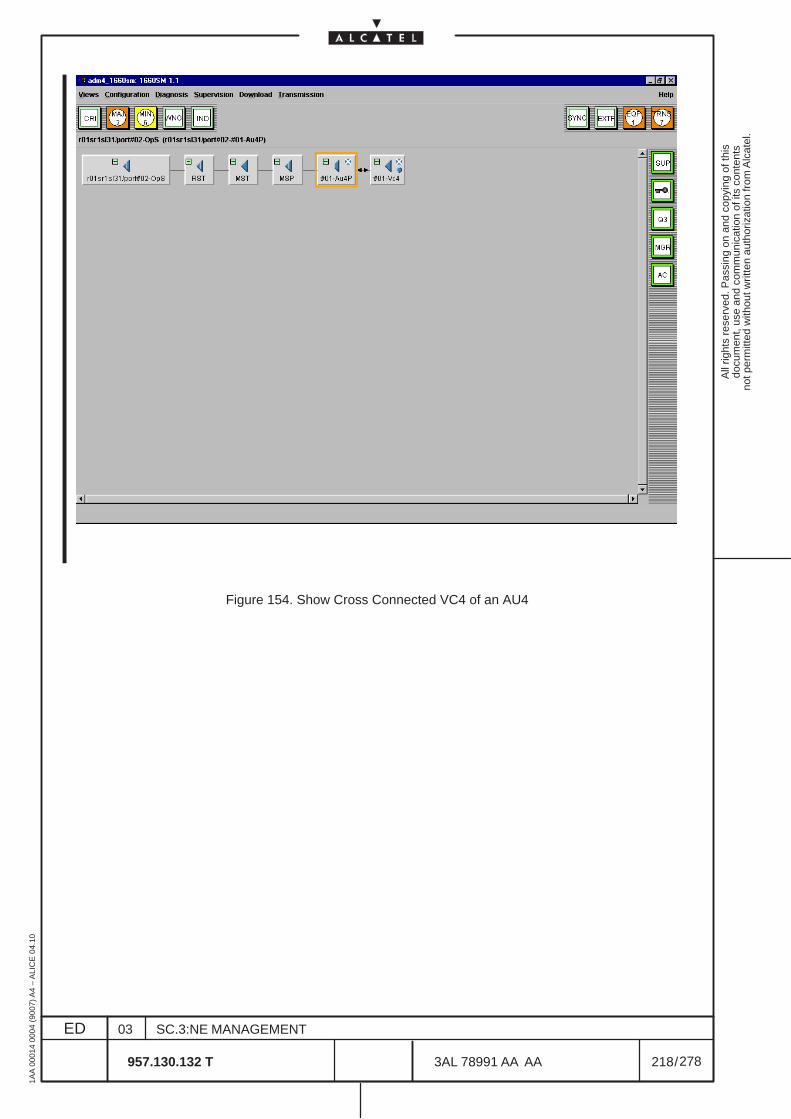
All
right
s re
serv
ed. P
assi
ng o
n an
d co
pyin
g of
this
docu
men
t, us
e an
d co
mm
unic
atio
n of
its
cont
ents
not p
erm
itted
with
out w
ritte
n au
thor
izat
ion
from
Alc
atel
.
ED
1AA
000
14 0
004
(900
7) A
4 –
ALI
CE
04.
10
218
03
957.130.132 T
SC.3:NE MANAGEMENT
/3AL 78991 AA AA
278
278
Figure 154. Show Cross Connected VC4 of an AU4
All
right
s re
serv
ed. P
assi
ng o
n an
d co
pyin
g of
this
docu
men
t, us
e an
d co
mm
unic
atio
n of
its
cont
ents
not p
erm
itted
with
out w
ritte
n au
thor
izat
ion
from
Alc
atel
.
ED
1AA
000
14 0
004
(900
7) A
4 –
ALI
CE
04.
10
219
03
957.130.132 T
SC.3:NE MANAGEMENT
/3AL 78991 AA AA
278
278
16 OVERHEAD MANAGEMENT
16.1 Introduction
The purpose of this set of dialogs is to handle the operations on the Overhead (OH) bytes of the NE.
The possible operations are:
• Overhead cross–connection
– Cross–connection between 2 or more OH bytes– Termination of an OH byte onto an auxiliary port or vocal channel– Total Pass–through of the MSOH bytes for some cards– Definition of the Phone Parameters
There is a TP associated to every OH byte and to every auxiliary port, so TP could be used instead ofOH bytes or auxiliary port, depending on the context.

All
right
s re
serv
ed. P
assi
ng o
n an
d co
pyin
g of
this
docu
men
t, us
e an
d co
mm
unic
atio
n of
its
cont
ents
not p
erm
itted
with
out w
ritte
n au
thor
izat
ion
from
Alc
atel
.
ED
1AA
000
14 0
004
(900
7) A
4 –
ALI
CE
04.
10
220
03
957.130.132 T
SC.3:NE MANAGEMENT
/3AL 78991 AA AA
278
278
16.2 OH Connection overview
Here are described the possible OH connections
For OH Phone Parameters directly refer to the para 16.7 on page 229.
– OH Cross–connection
The operator has to be able to cross–connect 2 or more OH bytes on 2 different boards.
The possible cross–connection types are:• unprotected bidirectional point to point
The steps an operator has to do in order to perform the cross–connection are the following:
• create the OH TPs involved in the operation• create the OH cross–connection:
– select type of cross–connection– select the input OH TP involved in the operation– select the output OH TP involved in the operation
After having deleted an OH cross–connection, the involved TPs have to be deleted.
– OH Termination
The operator has to be able to terminate one OH byte onto an auxiliary port or vocal channel.
The steps an operator has to do in order to perform the OH bytes termination are the following:• create the OH TP involved in the operation• create the OH byte termination:
– select the created OH TP– select the auxiliary port/vocal channel TP involved in the operation
After having deleted an OH byte termination, the involved TP have to be deleted.
– Total MSOH Pass–through
For STM ports it make sense to allow the operator to perform a total pass–through of the MSOH bytes.A total msoh pass–through connection (connection between msPassThroughCTP points) is set–up onlyif no single msoh pass–through connection are set and if no single msoh cross–connection are set. If atotal msoh pass–through connection is set, a single msoh pass–through connection or a single msohcross–connection cannot be set.
The steps an operator has to do in order to perform the total MSOH pass–through are the following:• create the msPassThroughCTP points involved in the operation• create the total MSOH pass–through:
– select the input msPassThroughCTP point involved in the operation– select the output msPassThroughCTP point involved in the operation
After having deleted a total MSOH pass–through, the involved msPassThroughCTP points have to bedeleted.
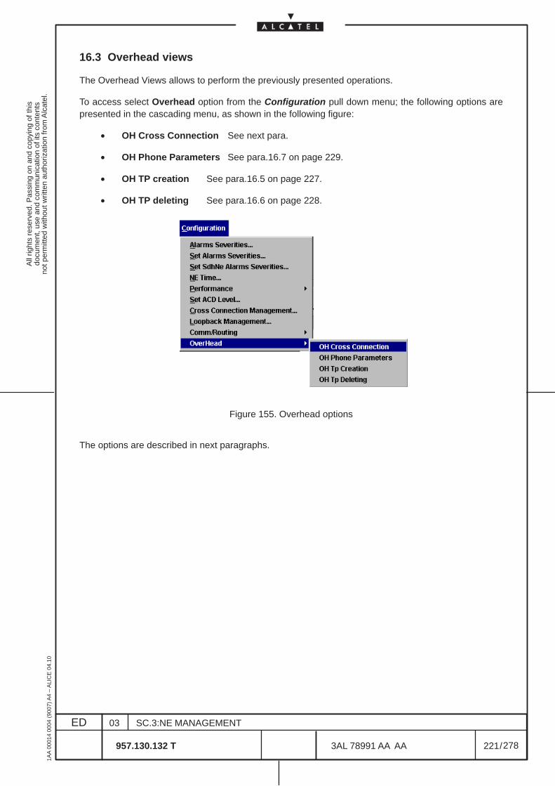
All
right
s re
serv
ed. P
assi
ng o
n an
d co
pyin
g of
this
docu
men
t, us
e an
d co
mm
unic
atio
n of
its
cont
ents
not p
erm
itted
with
out w
ritte
n au
thor
izat
ion
from
Alc
atel
.
ED
1AA
000
14 0
004
(900
7) A
4 –
ALI
CE
04.
10
221
03
957.130.132 T
SC.3:NE MANAGEMENT
/3AL 78991 AA AA
278
278
16.3 Overhead views
The Overhead Views allows to perform the previously presented operations.
To access select Overhead option from the Configuration pull down menu; the following options arepresented in the cascading menu, as shown in the following figure:
• OH Cross Connection See next para.
• OH Phone Parameters See para.16.7 on page 229.
• OH TP creation See para.16.5 on page 227.
• OH TP deleting See para.16.6 on page 228.
Figure 155. Overhead options
The options are described in next paragraphs.
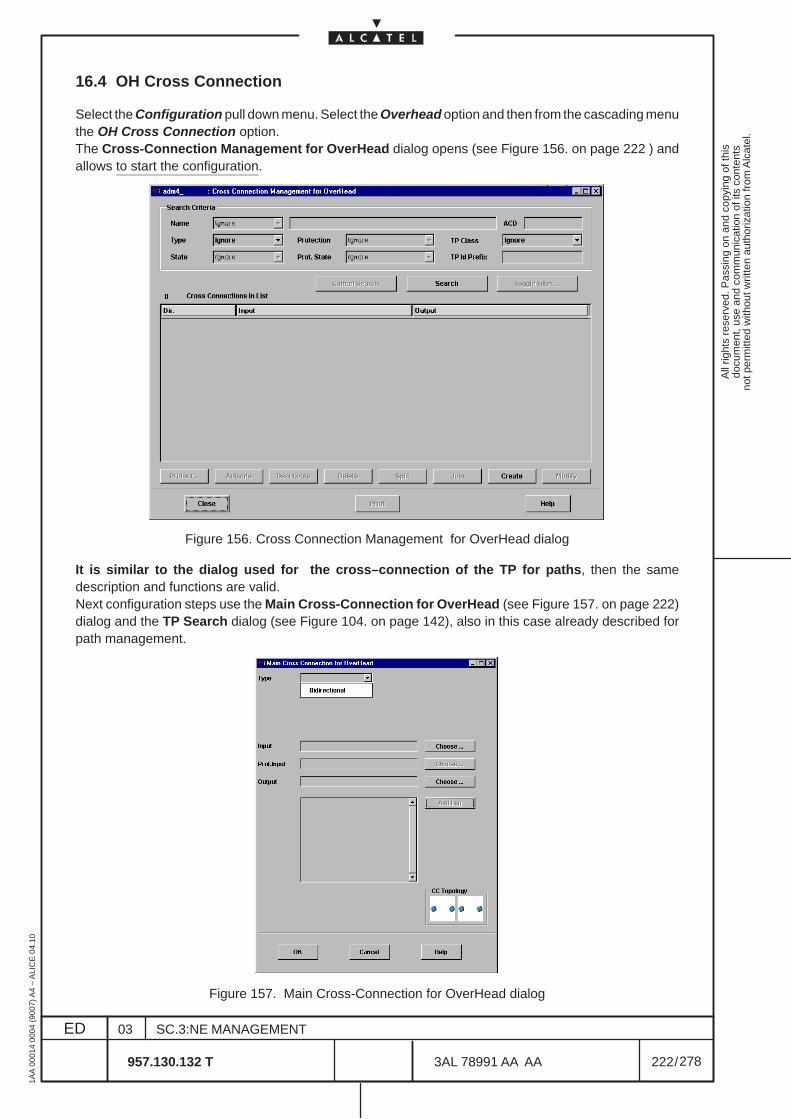
All
right
s re
serv
ed. P
assi
ng o
n an
d co
pyin
g of
this
docu
men
t, us
e an
d co
mm
unic
atio
n of
its
cont
ents
not p
erm
itted
with
out w
ritte
n au
thor
izat
ion
from
Alc
atel
.
ED
1AA
000
14 0
004
(900
7) A
4 –
ALI
CE
04.
10
222
03
957.130.132 T
SC.3:NE MANAGEMENT
/3AL 78991 AA AA
278
278
16.4 OH Cross Connection
Select the Configuration pull down menu. Select the Overhead option and then from the cascading menuthe OH Cross Connection option.The Cross-Connection Management for OverHead dialog opens (see Figure 156. on page 222 ) andallows to start the configuration.
Figure 156. Cross Connection Management for OverHead dialog
It is similar to the dialog used for the cross–connection of the TP for paths, then the samedescription and functions are valid.Next configuration steps use the Main Cross-Connection for OverHead (see Figure 157. on page 222)dialog and the TP Search dialog (see Figure 104. on page 142), also in this case already described forpath management.
Figure 157. Main Cross-Connection for OverHead dialog
All
right
s re
serv
ed. P
assi
ng o
n an
d co
pyin
g of
this
docu
men
t, us
e an
d co
mm
unic
atio
n of
its
cont
ents
not p
erm
itted
with
out w
ritte
n au
thor
izat
ion
from
Alc
atel
.
ED
1AA
000
14 0
004
(900
7) A
4 –
ALI
CE
04.
10
223
03
957.130.132 T
SC.3:NE MANAGEMENT
/3AL 78991 AA AA
278
278
For all details, navigation and sequences on these views refer to chapter 15 on page 173.
There is one big difference between the OH TPs and the other kinds of TPs: the OH TPs have to be:• created ONLY BEFORE a cross–connection/termination operation involving them has been
performed.• deleted AFTER a cross–connection/termination deleting involving them has been confirmed.
The current implementation of the TP Search Dialog (TPSD) works only with created TPs.In the following a description of the main functions and commands is given, also to list the Supported andNot Supported operation.
16.4.1 Cross-Connection Management for OverHead dialog
See Figure 156. on page 222
– Supported operations
• Search cross connections/terminations according to one or more of the following filteringattributes: type, TPs . The operator can set the filtering criteria, can start the search and selectone or more cross connections/terminations among those presented in a read–only list as aresult of the search operation. For each crossconnection/termination matching the filteringcriteria, the following information is shown: direction (bidirectional) and the input, output TPsinvolved ;
After choosing one or more cross connections/terminations, this dialog allows to:
• Delete the selected xconnection/termination• Go to the “Main Cross Connection for OverHead” dialog and modify the existing cross
connection/termination
Note: this dialog disappears only when the user explicitly clicks on the close button.
Delete operations can be performed on several cross connections/termination at the same time.Modify operations can be performed only on single cross connections/terminations.The OH xconnections are automatically active at the moment of their creation.
The operation buttons availability follows some rules:
• The Delete and Print buttons are enabled only if at least one item is selected from the list.A special dialog will ask the user for a confirmation.
• the modify button is enabled if one (and only one) item is selected. It brings up the Maincrossconnection dialog.
• the create button is always enabled. It brings up the Main crossconnection Dialog.
When some operation may affect the existing traffic, the operator is warned about that, and a confirmationdialog must be answered to carry on/cancel the operation. The choices for this dialog are: yes/no forsingle items, yes to all/cancel for multiple items
– Not Supported operation
When used for OH purposes, the Cross-Connection Management dialog doesn’t support the followingfunctionalities:
• Protect cross connections/terminations: all the OH cross connections/terminations areunprotected
• Activate/Deactivate cross connections/terminations: all the OH crossconnections/terminations are automatically active since their creation
All
right
s re
serv
ed. P
assi
ng o
n an
d co
pyin
g of
this
docu
men
t, us
e an
d co
mm
unic
atio
n of
its
cont
ents
not p
erm
itted
with
out w
ritte
n au
thor
izat
ion
from
Alc
atel
.
ED
1AA
000
14 0
004
(900
7) A
4 –
ALI
CE
04.
10
224
03
957.130.132 T
SC.3:NE MANAGEMENT
/3AL 78991 AA AA
278
278
16.4.1.1 Main Cross-Connection for OverHead dialog
See Figure 157. on page 222.
According to the philosophy of offering only meaningful operations to the user, and being the OHcrossconnection operations a subset of those applying to the general cross connections (e.g:protectionsare not allowed), some fields of this dialog are disabled.
By clicking on the proper portions of the dialog and on the proper buttons, the operator can perform theoperations hereafter listed:
• selection of the cross–connection type
• selection of the input TP involved in the cross–connection
• selection of the output TP involved in the cross–connection
In order to do that the operator can either type in the involved TPs ID or use the TP Search dialog.
– Supported operations
• When creating a new cross connection, some or all of the following operations are available,depending on the NE type characteristics:– Choose bidirectional– Choose one input TP and one output TP. It is possible to directly type in the TP name or
to click on the Choose button to select a TP from the TP Search dialog box
• When modifying an existing cross connection, the same operations are available. Somechanges, may be traffic–affecting, as they may imply a temporary cross connectionsdestruction. In these cases a proper dialog box forces the user to confirm the operation. In theproper part of the dialog, an icon shows the icon of the selected existing cross connection. ForOH handling, these icons cannot be used to change the topology.
All
right
s re
serv
ed. P
assi
ng o
n an
d co
pyin
g of
this
docu
men
t, us
e an
d co
mm
unic
atio
n of
its
cont
ents
not p
erm
itted
with
out w
ritte
n au
thor
izat
ion
from
Alc
atel
.
ED
1AA
000
14 0
004
(900
7) A
4 –
ALI
CE
04.
10
225
03
957.130.132 T
SC.3:NE MANAGEMENT
/3AL 78991 AA AA
278
278
16.4.1.2 TP Search dialog
The TP Search dialog (see Figure 104. on page 142) currently offers:
• navigation rack/subrack/board/port
• a list of TPs to choose from
When used in the OH domain, this dialog is a subcase of the most generic TP Search.
The operator can choose among a list of:
• all the possible OH TPs belonging to a specified class: no board selected and MS, RS or VCclass selected
• all the possible OH TPs belonging to a specified board/port: board/port selected and no TPclass selected
• all the possible OH TPs belonging to a specified board/port and class: board/port selected andMS, RS or VC class selected
• all the OH TPs already connected (also accordingly to the connection type)
• all the OH TPs not yet connected
• a combination of the above options
In this Network Element to connect the auxiliary / vocal channels and the Overhead bytes thefollowing operative indication must be observed:
– the auxiliary and vocal channels TPs are in the SERVICE board of slot 11
The auxiliary channels are:
• 2 x G.703 2 Mbit/s; in the screen are indicated as:
– r01sr1sl11/port#01–PExpanding this TP, 31 referred TPs are presented from“r01sr1sl11/port#01–#1–1–e0CTP“ to “r01sr1sl11/port#01–#1–31–e0CTP“
– r01sr1sl11/port#01–PExpanding this TP, 31 referred TPs are presented from“r01sr1sl11/port#02–#1–1–e0CTP“ to “r01sr1sl11/port#02–#1–31–e0CTP
• 4 x G.703 64Kbit/s; in the screen are indicated as:
– r01sr1sl11/port#03–P– r01sr1sl11/port#04–P– r01sr1sl11/port#05–P– r01sr1sl11/port#06–P
• 4 x V11; in the screen are indicated as:
– r01sr1sl11/port#01–#01–v11TTP– r01sr1sl11/port#02–#01–v11TTP– r01sr1sl11/port#03–#01–v11TTP– r01sr1sl11/port#04–#01–v11TTP
All
right
s re
serv
ed. P
assi
ng o
n an
d co
pyin
g of
this
docu
men
t, us
e an
d co
mm
unic
atio
n of
its
cont
ents
not p
erm
itted
with
out w
ritte
n au
thor
izat
ion
from
Alc
atel
.
ED
1AA
000
14 0
004
(900
7) A
4 –
ALI
CE
04.
10
226
03
957.130.132 T
SC.3:NE MANAGEMENT
/3AL 78991 AA AA
278
278
• 4 x V24; in the screen are indicated as:
– r01sr1sl11/port#01–#01–v24TTP– r01sr1sl11/port#02–#01–v24TTP– r01sr1sl11/port#03–#01–v24TTP– r01sr1sl11/port#04–#01–v24TTP
• 1 x phonic interface (voice channel); in the screen are indicated as:
– r01sr1sl11/port#01–#01–q23TTPExpanding this TP, four referred TPs are presented:• r01sr1sl11/port#01–#001–q23TTP• r01sr1sl11/port#01–#002–q23TTP• r01sr1sl11/port#01–#003–q23TTP• r01sr1sl11/port#01–#004–q23TTP
These TPs permit to connect the voice channel toward four directions.
– The other boards used to terminate or cross–connect the OH bytes are the STM–n boards.The OH TP are present in MS, RS and VC4 TP Class.In these TPs the indication “......#0011 to 0099 (MS or RS) are referred to the coordinates of theSection OverHead bytes on the SDH frame (1,1 to 9,9).
The examples of the figure in this OH connection chapter can be helpful to the operator.

All
right
s re
serv
ed. P
assi
ng o
n an
d co
pyin
g of
this
docu
men
t, us
e an
d co
mm
unic
atio
n of
its
cont
ents
not p
erm
itted
with
out w
ritte
n au
thor
izat
ion
from
Alc
atel
.
ED
1AA
000
14 0
004
(900
7) A
4 –
ALI
CE
04.
10
227
03
957.130.132 T
SC.3:NE MANAGEMENT
/3AL 78991 AA AA
278
278
16.5 OH TP creation
Select the Configuration pull down menu. Select the Overhead option and then from the cascading menuthe OH TP creation option.The OH TP creation dialog opens (see Figure 158. ) and allows to create the OH TP to cross connect.
In detail, the dialog–box contains the following graphical object:
– a Choose button is used to display a list of OH Tps to be created. The Choose button startsthe TP Search (see Figure 159. ) with predefined filtering; the TP Search dialog allows theoperator to visualize only not created OH Tps.To visualize the OH TP in the TP Search view double click on the MS, RS or VC4 Tp.
– OH Tp field displays the label of the selected OH Tp to be created.
Apply button is used to perform a create request of the tp displayed in the OH Tp field. After havingperformed the create request, the OH Tp field is set to empty.Close button close the dialog without changes of the data.Help button provides some useful information about the dialog.
Figure 158. OH TP creation
Figure 159. OH Search TP for creation
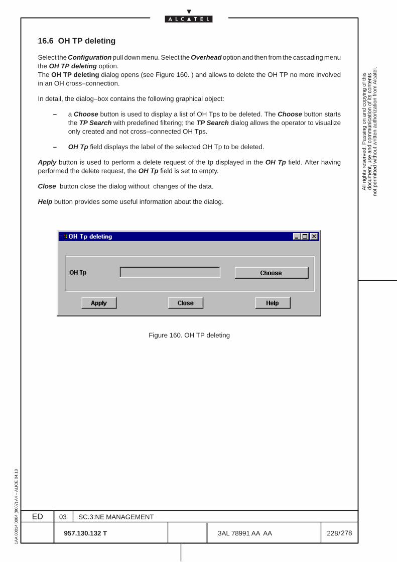
All
right
s re
serv
ed. P
assi
ng o
n an
d co
pyin
g of
this
docu
men
t, us
e an
d co
mm
unic
atio
n of
its
cont
ents
not p
erm
itted
with
out w
ritte
n au
thor
izat
ion
from
Alc
atel
.
ED
1AA
000
14 0
004
(900
7) A
4 –
ALI
CE
04.
10
228
03
957.130.132 T
SC.3:NE MANAGEMENT
/3AL 78991 AA AA
278
278
16.6 OH TP deleting
Select the Configuration pull down menu. Select the Overhead option and then from the cascading menuthe OH TP deleting option.The OH TP deleting dialog opens (see Figure 160. ) and allows to delete the OH TP no more involvedin an OH cross–connection.
In detail, the dialog–box contains the following graphical object:
– a Choose button is used to display a list of OH Tps to be deleted. The Choose button startsthe TP Search with predefined filtering; the TP Search dialog allows the operator to visualizeonly created and not cross–connected OH Tps.
– OH Tp field displays the label of the selected OH Tp to be deleted.
Apply button is used to perform a delete request of the tp displayed in the OH Tp field. After havingperformed the delete request, the OH Tp field is set to empty.
Close button close the dialog without changes of the data.
Help button provides some useful information about the dialog.
Figure 160. OH TP deleting
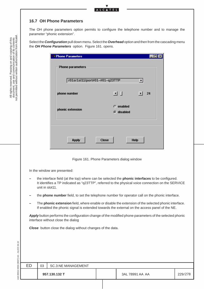
All
right
s re
serv
ed. P
assi
ng o
n an
d co
pyin
g of
this
docu
men
t, us
e an
d co
mm
unic
atio
n of
its
cont
ents
not p
erm
itted
with
out w
ritte
n au
thor
izat
ion
from
Alc
atel
.
ED
1AA
000
14 0
004
(900
7) A
4 –
ALI
CE
04.
10
229
03
957.130.132 T
SC.3:NE MANAGEMENT
/3AL 78991 AA AA
278
278
16.7 OH Phone Parameters
The OH phone parameters option permits to configure the telephone number and to manage theparameter “phonic extension”.
Select the Configuration pull down menu. Select the Overhead option and then from the cascading menuthe OH Phone Parameters option. Figure 161. opens.
r01sr1sl11/port#01–#01–q23TTP
Figure 161. Phone Parameters dialog window
In the window are presented:
– the interface field (at the top) where can be selected the phonic interfaces to be configured.It identifies a TP indicated as “q23TTP”, referred to the physical voice connection on the SERVICEunit in slot11.
– the phone number field, to set the telephone number for operator call on the phonic interface.
– The phonic extension field, where enable or disable the extension of the selected phonic interface.If enabled the phonic signal is extended towards the external on the access panel of the NE.
Apply button performs the configuration change of the modified phone parameters of the selected phonicinterface without close the dialog
Close button close the dialog without changes of the data.
All
right
s re
serv
ed. P
assi
ng o
n an
d co
pyin
g of
this
docu
men
t, us
e an
d co
mm
unic
atio
n of
its
cont
ents
not p
erm
itted
with
out w
ritte
n au
thor
izat
ion
from
Alc
atel
.
ED
1AA
000
14 0
004
(900
7) A
4 –
ALI
CE
04.
10
230
03
957.130.132 T
SC.3:NE MANAGEMENT
/3AL 78991 AA AA
278
278
All
right
s re
serv
ed. P
assi
ng o
n an
d co
pyin
g of
this
docu
men
t, us
e an
d co
mm
unic
atio
n of
its
cont
ents
not p
erm
itted
with
out w
ritte
n au
thor
izat
ion
from
Alc
atel
.
ED
1AA
000
14 0
004
(900
7) A
4 –
ALI
CE
04.
10
231
03
957.130.132 T
SC.3:NE MANAGEMENT
/3AL 78991 AA AA
278
278
17 PERFORMANCE MONITORING
17.1 Introduction
The Performance Monitoring domain on the NE covers the monitoring of counter values for trailtermination points and connection termination points.
Examples of these counters are Errored Seconds (ES) and Severely Errored Seconds (SES).
The Performance Monitoring domain counts these errors during specified granularity periods (15 min,24h) and stores the values in history data logs.
For the purpose of quality supervision, the values of the error counters can be compared to user-definedthreshold levels. If a counter value has crossed a threshold level, a notification (threshold crossing alarm)is issued.
The principle performance management functions are:
– Configuration of the counting interval for each performance measurement point.
– Collection of the performance data.
– Configuration of the quality thresholds that generate alarms and log records when predefined valuesare exceeded.
17.1.1 Overview
These functionalities are described in the following chapters in addition to general information concerningperformance monitoring on the NE.
– Chapter Configuration deals with the configuration of performance monitoring
– Chapter Display Current Data deals with displaying current performance data
– Chapter Display History Data deals with displaying history performance data
– Chapter PM Threshold Table Selection deals with the selection of threshold tables
– Chapter PM Threshold Table Modification/Display deals with the modification of threshold tablesand permits to display the same
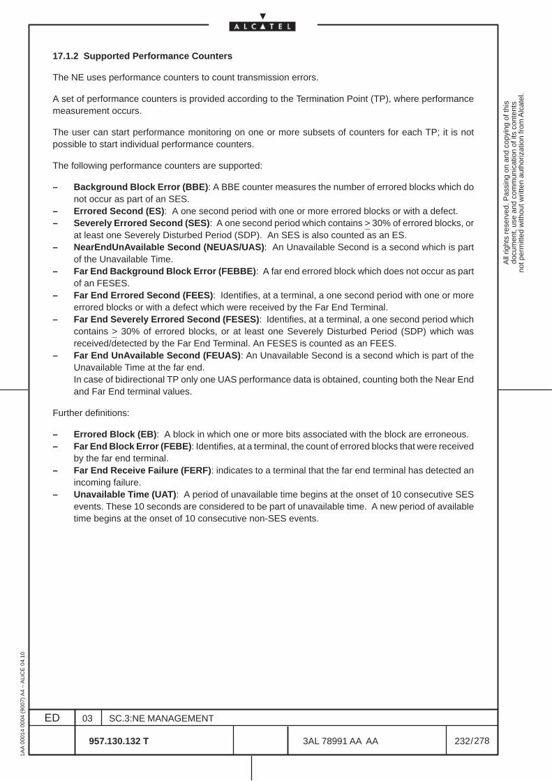
All
right
s re
serv
ed. P
assi
ng o
n an
d co
pyin
g of
this
docu
men
t, us
e an
d co
mm
unic
atio
n of
its
cont
ents
not p
erm
itted
with
out w
ritte
n au
thor
izat
ion
from
Alc
atel
.
ED
1AA
000
14 0
004
(900
7) A
4 –
ALI
CE
04.
10
232
03
957.130.132 T
SC.3:NE MANAGEMENT
/3AL 78991 AA AA
278
278
17.1.2 Supported Performance Counters
The NE uses performance counters to count transmission errors.
A set of performance counters is provided according to the Termination Point (TP), where performancemeasurement occurs.
The user can start performance monitoring on one or more subsets of counters for each TP; it is notpossible to start individual performance counters.
The following performance counters are supported:
– Background Block Error (BBE): A BBE counter measures the number of errored blocks which donot occur as part of an SES.
– Errored Second (ES): A one second period with one or more errored blocks or with a defect.– Severely Errored Second (SES): A one second period which contains > 30% of errored blocks, or
at least one Severely Disturbed Period (SDP). An SES is also counted as an ES.– NearEndUnAvailable Second (NEUAS/UAS): An Unavailable Second is a second which is part
of the Unavailable Time.– Far End Background Block Error (FEBBE): A far end errored block which does not occur as part
of an FESES.– Far End Errored Second (FEES): Identifies, at a terminal, a one second period with one or more
errored blocks or with a defect which were received by the Far End Terminal.– Far End Severely Errored Second (FESES): Identifies, at a terminal, a one second period which
contains > 30% of errored blocks, or at least one Severely Disturbed Period (SDP) which wasreceived/detected by the Far End Terminal. An FESES is counted as an FEES.
– Far End UnAvailable Second (FEUAS): An Unavailable Second is a second which is part of theUnavailable Time at the far end.In case of bidirectional TP only one UAS performance data is obtained, counting both the Near Endand Far End terminal values.
Further definitions:
– Errored Block (EB): A block in which one or more bits associated with the block are erroneous.– Far End Block Error (FEBE): Identifies, at a terminal, the count of errored blocks that were received
by the far end terminal.– Far End Receive Failure (FERF): indicates to a terminal that the far end terminal has detected an
incoming failure.– Unavailable Time (UAT): A period of unavailable time begins at the onset of 10 consecutive SES
events. These 10 seconds are considered to be part of unavailable time. A new period of availabletime begins at the onset of 10 consecutive non-SES events.
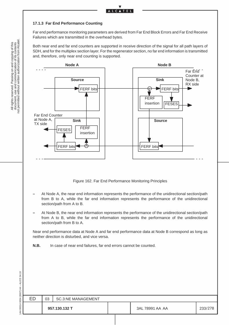
All
right
s re
serv
ed. P
assi
ng o
n an
d co
pyin
g of
this
docu
men
t, us
e an
d co
mm
unic
atio
n of
its
cont
ents
not p
erm
itted
with
out w
ritte
n au
thor
izat
ion
from
Alc
atel
.
ED
1AA
000
14 0
004
(900
7) A
4 –
ALI
CE
04.
10
233
03
957.130.132 T
SC.3:NE MANAGEMENT
/3AL 78991 AA AA
278
278
17.1.3 Far End Performance Counting
Far end performance monitoring parameters are derived from Far End Block Errors and Far End ReceiveFailures which are transmitted in the overhead bytes.
Both near end and far end counters are supported in receive direction of the signal for all path layers ofSDH, and for the multiplex section layer. For the regenerator section, no far end information is transmittedand, therefore, only near end counting is supported.
FERF bits
FERF insertion
FERF bits
Source
Sink
FESES
FERFinsertion
FERF bits
Sink
FESES
FERF bits
Source
Node A Node B
Far EndCounter atNode B, RX side
Far End Counterat Node A,TX side
Figure 162. Far End Performance Monitoring Principles
– At Node A, the near end information represents the performance of the unidirectional section/pathfrom B to A, while the far end information represents the performance of the unidirectionalsection/path from A to B.
– At Node B, the near end information represents the performance of the unidirectional section/pathfrom A to B, while the far end information represents the performance of the unidirectionalsection/path from B to A.
Near end performance data at Node A and far end performance data at Node B correspond as long asneither direction is disturbed, and vice versa.
N.B. In case of near end failures, far end errors cannot be counted.
All
right
s re
serv
ed. P
assi
ng o
n an
d co
pyin
g of
this
docu
men
t, us
e an
d co
mm
unic
atio
n of
its
cont
ents
not p
erm
itted
with
out w
ritte
n au
thor
izat
ion
from
Alc
atel
.
ED
1AA
000
14 0
004
(900
7) A
4 –
ALI
CE
04.
10
234
03
957.130.132 T
SC.3:NE MANAGEMENT
/3AL 78991 AA AA
278
278
17.1.4 Granularity
A monitoring period of defined granularity is associated with each performance counter.
This NE supports unidirectional PM of 15 minute and 24 hour granularity and bidirectional PM for 24 hourgranularity. After the monitoring period has elapsed, the performance data is stored in the associatedhistory data log.
Time stamping of history records is performed using UTC (as for all alarms).The measurement intervals start at 00 : 00 (UTC) for 24-hour periods and at xx : 00, xx : 15, xx : 30 andxx : 45 for 15-minute periods.
17.1.5 Data Collection
N.B. PM data is not counted on boards that were plugged out at the moment of enabling datacollection (see PM Configuration dialog). Nevertheless, PM data is counted on boards thatwere plugged in at the moment of enabling data collection, but were plugged out and back insome time during data collection.
Performance Monitoring can be started at any time.
As soon as Performance Monitoring is started on the Craft Terminal, current PM data is collected on theI/O boards, incrementing the performance counters each time an error is detected.The performance data counted is evaluated every quarter of an hour or every 24 hours and stored therein a history record.
When the user disables the monitoring of a TP within the first 10 minutes of a 15-minute period, it ispossible that have still not been received the PM data of the previous monitoring interval.Since PM data is not stored after monitoring is disabled, the PM data of the previous interval is lost in thiscase.
If equipment or line protection switching occurs during a counting interval, the NE does not providecomplete performance measurement for the protected TPs.Only the period between the last switch and the end of the counting window is counted.The interval is marked for suspect data and the elapsed time indicates the length of the measured period.
All
right
s re
serv
ed. P
assi
ng o
n an
d co
pyin
g of
this
docu
men
t, us
e an
d co
mm
unic
atio
n of
its
cont
ents
not p
erm
itted
with
out w
ritte
n au
thor
izat
ion
from
Alc
atel
.
ED
1AA
000
14 0
004
(900
7) A
4 –
ALI
CE
04.
10
235
03
957.130.132 T
SC.3:NE MANAGEMENT
/3AL 78991 AA AA
278
278
17.1.6 Thresholds
For quality supervision purposes, the recorded errors through the performance counters can be comparedto threshold levels. If a counter value has crossed a threshold level, a Threshold Crossing Alarm (TCA)is transmitted to the alarm manager.
The threshold values are defined in threshold tables together with a severity and a flag indicating whethercrossing this value should be notified by an alarm and logged or only stored in the current problem list.The user can modify and delete such tables.
Different thresholds can be assigned for near end and far end and for granularity of 15 minutes and 24hours.
The TCA only reports the value of the counter which has crossed the threshold, it does not provide acomplete set of all counters. Therefore, the user has to explicitly retrieve all current performance data afterreceiving the alarm. The user can retrieve this information from a dialog.
The system behavior concerning the clearance of 15 min. and 24 h TCAs differs:
– 15 min. (explicit clearance):A TCA is only indicated once in the alarm manager, even if the same threshold is crossed severaltimes a day.TCAs are automatically cleared by the system after one error-free 15 min. interval.
– 24 h (implicit clearance):A TCA is indicated for each interval in which the related threshold has been crossed. The systemimplicitly clear TCAs, at the end of the 24 hours.
The following limitations apply for explicit clearance:– The value of the low threshold is fixed to “0” (only a single threshold is provided by a threshold table).– An SES threshold crossing is cleared at the end of the interval if no unavailability was detected and
SES had not reached the low threshold (low threshold equal to 0).– Even in case of a suspect interval the TCA is cleared if no unavailability was detected and the low
threshold had not been reached.
Additionally an explicit clearance of TCAs for all granularity periods is executed if one of the followingevents occurs during the current interval:
– deletion of the current data instance,
– resetting of counters,
– increased thresholds (higher than current value of counters).
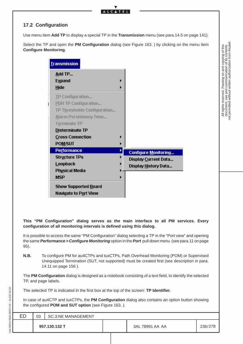
All
right
s re
serv
ed. P
assi
ng o
n an
d co
pyin
g of
this
docu
men
t, us
e an
d co
mm
unic
atio
n of
its
cont
ents
not p
erm
itted
with
out w
ritte
n au
thor
izat
ion
from
Alc
atel
.
ED
1AA
000
14 0
004
(900
7) A
4 –
ALI
CE
04.
10
236
03
957.130.132 T
SC.3:NE MANAGEMENT
/3AL 78991 AA AA
278
278
17.2 Configuration
Use menu item Add TP to display a special TP in the Transmission menu (see para.14.5 on page 141).
Select the TP and open the PM Configuration dialog (see Figure 163. ) by clicking on the menu itemConfigure Monitoring.
This “PM Configuration” dialog serves as the main interface to all PM services. Everyconfiguration of all monitoring intervals is defined using this dialog.
It is possible to access the same “PM Configuration” dialog selecting a TP in the “Port view” and openingthe same Performance > Configure Monitoring option in the Port pull down menu (see para.11 on page95).
N.B. To configure PM for au4CTPs and tuxCTPs, Path Overhead Monitoring (POM) or SupervisedUnequipped Termination (SUT, not supported) must be created first (see description in para.14.11 on page 156 ).
The PM Configuration dialog is designed as a notebook consisting of a text field, to identify the selectedTP, and page labels.
The selected TP is indicated in the first box at the top of the screen: TP Identifier.
In case of au4CTP and tuxCTPs, the PM Configuration dialog also contains an option button showingthe configured POM and SUT option (see Figure 163. ).
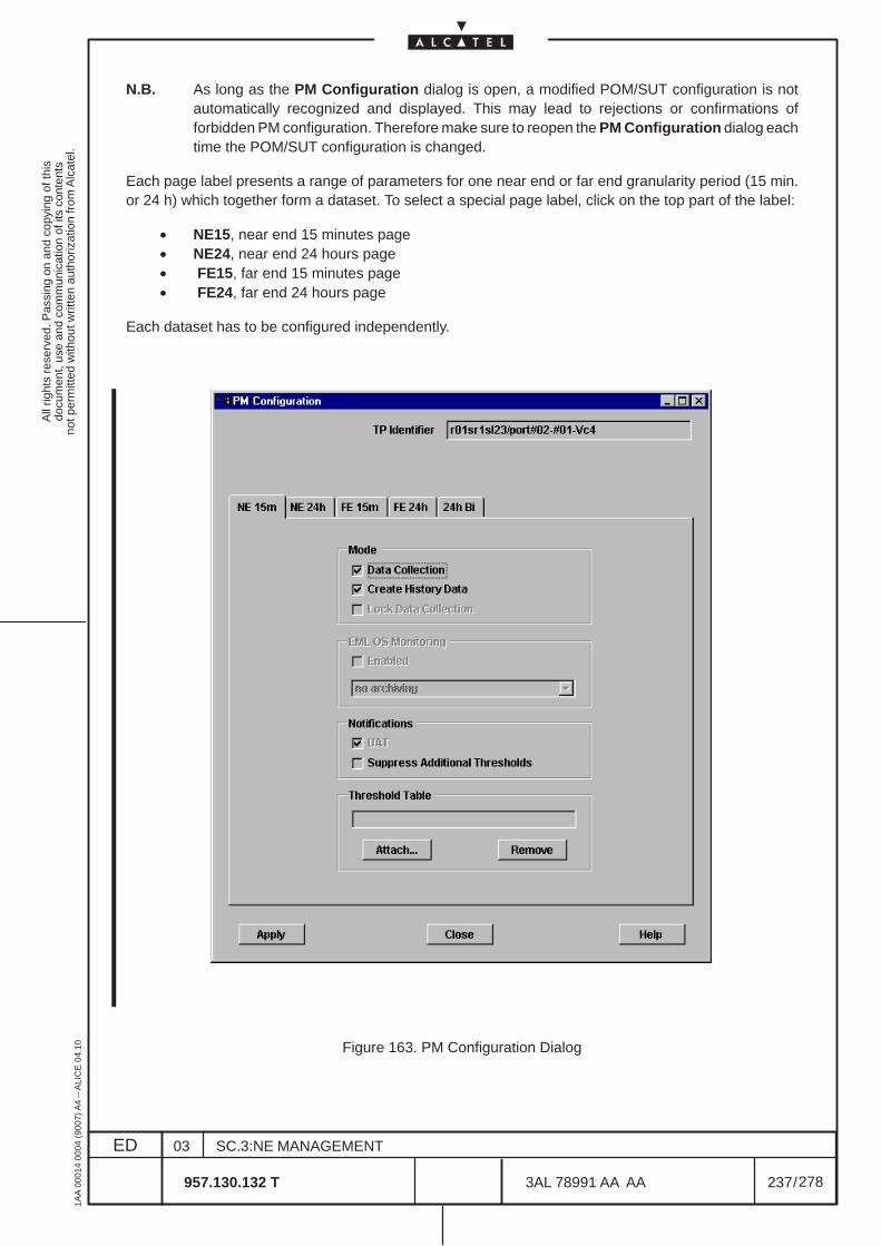
All
right
s re
serv
ed. P
assi
ng o
n an
d co
pyin
g of
this
docu
men
t, us
e an
d co
mm
unic
atio
n of
its
cont
ents
not p
erm
itted
with
out w
ritte
n au
thor
izat
ion
from
Alc
atel
.
ED
1AA
000
14 0
004
(900
7) A
4 –
ALI
CE
04.
10
237
03
957.130.132 T
SC.3:NE MANAGEMENT
/3AL 78991 AA AA
278
278
N.B. As long as the PM Configuration dialog is open, a modified POM/SUT configuration is notautomatically recognized and displayed. This may lead to rejections or confirmations offorbidden PM configuration. Therefore make sure to reopen the PM Configuration dialog eachtime the POM/SUT configuration is changed.
Each page label presents a range of parameters for one near end or far end granularity period (15 min.or 24 h) which together form a dataset. To select a special page label, click on the top part of the label:
• NE15, near end 15 minutes page• NE24, near end 24 hours page• FE15, far end 15 minutes page• FE24, far end 24 hours page
Each dataset has to be configured independently.
Figure 163. PM Configuration Dialog
All
right
s re
serv
ed. P
assi
ng o
n an
d co
pyin
g of
this
docu
men
t, us
e an
d co
mm
unic
atio
n of
its
cont
ents
not p
erm
itted
with
out w
ritte
n au
thor
izat
ion
from
Alc
atel
.
ED
1AA
000
14 0
004
(900
7) A
4 –
ALI
CE
04.
10
238
03
957.130.132 T
SC.3:NE MANAGEMENT
/3AL 78991 AA AA
278
278
Activate any item within the page label by selecting the respective radio button.
– Mode
• Data Collection
Select this button to activate performance monitoring. Disabling Data Collection leads toclearance of the current and all history data of this entity.
• Create History Data
If this item is selected, history data collection is performed in the selected entity for thecorresponding TP.
Note that on disabling this mode item, no history data is available. Nevertheless, datasetscollected prior to deactivation are not cleared and are displayed after re-enabling the item, aslong as the number of displayed datasets does not exceed 16 for 15 min. granularity and threefor 24 hours granularity.
• Lock Data Collection. Not supported
If Lock is selected, PM remains enabled but data collection is stopped. All history performancedata remain available. All current values are set to zero.
– EML OS Monitoring (only accessible from SH)
Not available for Craft Terminal.
– Notifications
• UAT (only available for 24 h granularity)
For 24 h granularity, UAT (UnAvailable Time) notifications are created if enabled. Thisnotification results in an UAT alarm in the Alarm Surveillance.
N.B. This parameter can only be selected during creation and cannot be subsequentlymodified.
• Suppress Additional Threshold
Disabled: the alarm is generated every time the value exceed the upper threshold (value up).
Enabled: after a first alarm generation, the alarm is generated again when the value exceed theupper threshold (value up) after the lower threshold (value down) has been exceeded.
– Threshold Table
Attach a threshold table to the selected TP. Only assign threshold tables that match the granularityperiod of the datasets (i.e. a 15 min. threshold table must not be assigned to a 24 h dataset).Otherwise the Transmission view is blocked and only released by closing and reopening the PMConfiguration window and the Transmission view.Click on button Attach... to open the PM Threshold Table Select dialog (see Figure 166. ) andconfigure the threshold table (see Chapter 17.5 on page 243).Select button Remove to disassociate the threshold table from the entity.
N.B. A threshold table can only be attached if Data Collection is enabled.
Confirm the configuration with the button Apply before closing the dialog. Otherwise the configuration islost.
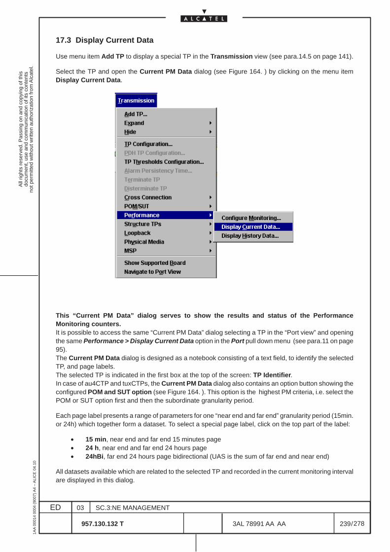
All
right
s re
serv
ed. P
assi
ng o
n an
d co
pyin
g of
this
docu
men
t, us
e an
d co
mm
unic
atio
n of
its
cont
ents
not p
erm
itted
with
out w
ritte
n au
thor
izat
ion
from
Alc
atel
.
ED
1AA
000
14 0
004
(900
7) A
4 –
ALI
CE
04.
10
239
03
957.130.132 T
SC.3:NE MANAGEMENT
/3AL 78991 AA AA
278
278
17.3 Display Current Data
Use menu item Add TP to display a special TP in the Transmission view (see para.14.5 on page 141).
Select the TP and open the Current PM Data dialog (see Figure 164. ) by clicking on the menu itemDisplay Current Data.
This “Current PM Data” dialog serves to show the results and status of the PerformanceMonitoring counters.It is possible to access the same “Current PM Data” dialog selecting a TP in the “Port view” and openingthe same Performance > Display Current Data option in the Port pull down menu (see para.11 on page95).The Current PM Data dialog is designed as a notebook consisting of a text field, to identify the selectedTP, and page labels.The selected TP is indicated in the first box at the top of the screen: TP Identifier.In case of au4CTP and tuxCTPs, the Current PM Data dialog also contains an option button showing theconfigured POM and SUT option (see Figure 164. ). This option is the highest PM criteria, i.e. select thePOM or SUT option first and then the subordinate granularity period.
Each page label presents a range of parameters for one “near end and far end” granularity period (15min.or 24h) which together form a dataset. To select a special page label, click on the top part of the label:
• 15 min, near end and far end 15 minutes page• 24 h, near end and far end 24 hours page• 24hBi, far end 24 hours page bidirectional (UAS is the sum of far end and near end)
All datasets available which are related to the selected TP and recorded in the current monitoring intervalare displayed in this dialog.
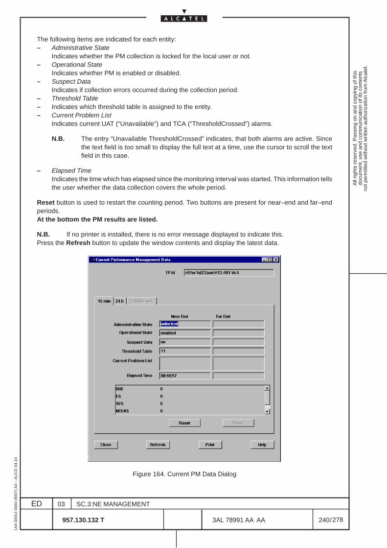
All
right
s re
serv
ed. P
assi
ng o
n an
d co
pyin
g of
this
docu
men
t, us
e an
d co
mm
unic
atio
n of
its
cont
ents
not p
erm
itted
with
out w
ritte
n au
thor
izat
ion
from
Alc
atel
.
ED
1AA
000
14 0
004
(900
7) A
4 –
ALI
CE
04.
10
240
03
957.130.132 T
SC.3:NE MANAGEMENT
/3AL 78991 AA AA
278
278
The following items are indicated for each entity:– Administrative State
Indicates whether the PM collection is locked for the local user or not.– Operational State
Indicates whether PM is enabled or disabled.– Suspect Data
Indicates if collection errors occurred during the collection period.– Threshold Table– Indicates which threshold table is assigned to the entity.– Current Problem List
Indicates current UAT (“Unavailable”) and TCA (“ThresholdCrossed”) alarms.
N.B. The entry “Unavailable ThresholdCrossed” indicates, that both alarms are active. Sincethe text field is too small to display the full text at a time, use the cursor to scroll the textfield in this case.
– Elapsed TimeIndicates the time which has elapsed since the monitoring interval was started. This information tellsthe user whether the data collection covers the whole period.
Reset button is used to restart the counting period. Two buttons are present for near–end and far–endperiods.At the bottom the PM results are listed.
N.B. If no printer is installed, there is no error message displayed to indicate this.Press the Refresh button to update the window contents and display the latest data.
Figure 164. Current PM Data Dialog
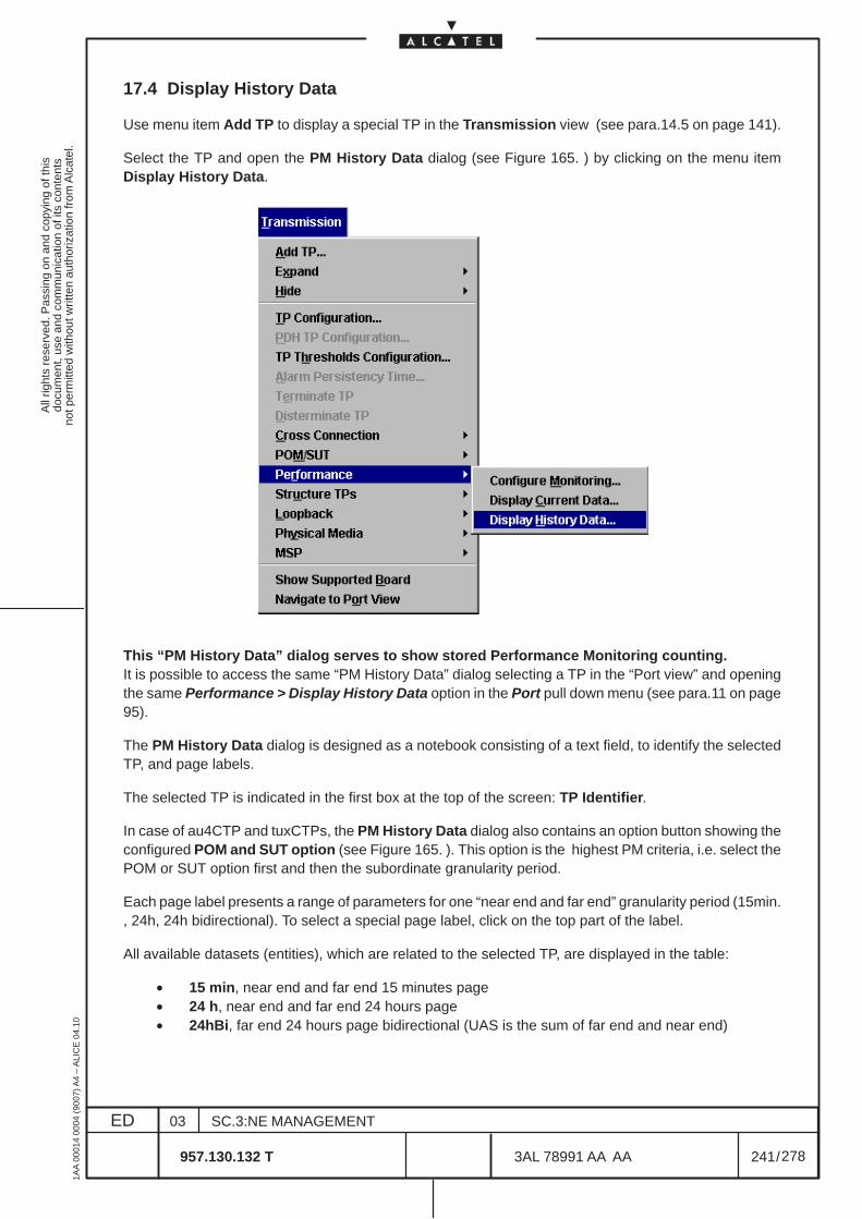
All
right
s re
serv
ed. P
assi
ng o
n an
d co
pyin
g of
this
docu
men
t, us
e an
d co
mm
unic
atio
n of
its
cont
ents
not p
erm
itted
with
out w
ritte
n au
thor
izat
ion
from
Alc
atel
.
ED
1AA
000
14 0
004
(900
7) A
4 –
ALI
CE
04.
10
241
03
957.130.132 T
SC.3:NE MANAGEMENT
/3AL 78991 AA AA
278
278
17.4 Display History Data
Use menu item Add TP to display a special TP in the Transmission view (see para.14.5 on page 141).
Select the TP and open the PM History Data dialog (see Figure 165. ) by clicking on the menu itemDisplay History Data.
This “PM History Data” dialog serves to show stored Performance Monitoring counting.It is possible to access the same “PM History Data” dialog selecting a TP in the “Port view” and openingthe same Performance > Display History Data option in the Port pull down menu (see para.11 on page95).
The PM History Data dialog is designed as a notebook consisting of a text field, to identify the selectedTP, and page labels.
The selected TP is indicated in the first box at the top of the screen: TP Identifier.
In case of au4CTP and tuxCTPs, the PM History Data dialog also contains an option button showing theconfigured POM and SUT option (see Figure 165. ). This option is the highest PM criteria, i.e. select thePOM or SUT option first and then the subordinate granularity period.
Each page label presents a range of parameters for one “near end and far end” granularity period (15min., 24h, 24h bidirectional). To select a special page label, click on the top part of the label.
All available datasets (entities), which are related to the selected TP, are displayed in the table:
• 15 min, near end and far end 15 minutes page• 24 h, near end and far end 24 hours page• 24hBi, far end 24 hours page bidirectional (UAS is the sum of far end and near end)
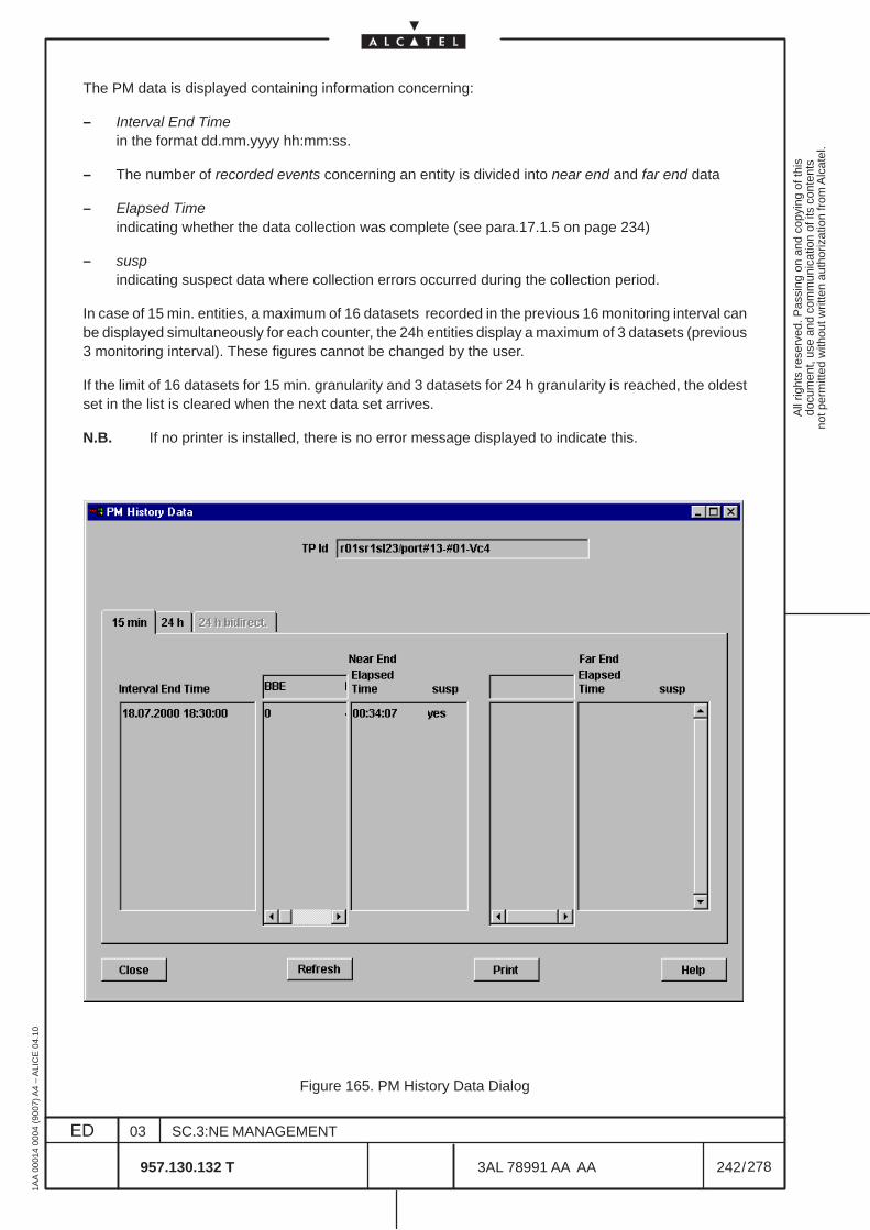
All
right
s re
serv
ed. P
assi
ng o
n an
d co
pyin
g of
this
docu
men
t, us
e an
d co
mm
unic
atio
n of
its
cont
ents
not p
erm
itted
with
out w
ritte
n au
thor
izat
ion
from
Alc
atel
.
ED
1AA
000
14 0
004
(900
7) A
4 –
ALI
CE
04.
10
242
03
957.130.132 T
SC.3:NE MANAGEMENT
/3AL 78991 AA AA
278
278
The PM data is displayed containing information concerning:
– Interval End Timein the format dd.mm.yyyy hh:mm:ss.
– The number of recorded events concerning an entity is divided into near end and far end data
– Elapsed Timeindicating whether the data collection was complete (see para.17.1.5 on page 234)
– suspindicating suspect data where collection errors occurred during the collection period.
In case of 15 min. entities, a maximum of 16 datasets recorded in the previous 16 monitoring interval canbe displayed simultaneously for each counter, the 24h entities display a maximum of 3 datasets (previous3 monitoring interval). These figures cannot be changed by the user.
If the limit of 16 datasets for 15 min. granularity and 3 datasets for 24 h granularity is reached, the oldestset in the list is cleared when the next data set arrives.
N.B. If no printer is installed, there is no error message displayed to indicate this.
Figure 165. PM History Data Dialog

All
right
s re
serv
ed. P
assi
ng o
n an
d co
pyin
g of
this
docu
men
t, us
e an
d co
mm
unic
atio
n of
its
cont
ents
not p
erm
itted
with
out w
ritte
n au
thor
izat
ion
from
Alc
atel
.
ED
1AA
000
14 0
004
(900
7) A
4 –
ALI
CE
04.
10
243
03
957.130.132 T
SC.3:NE MANAGEMENT
/3AL 78991 AA AA
278
278
17.5 PM THRESHOLD TABLE SELECTION
The PM Threshold Table Select dialog (see Figure 166. ) pops up if the Attach button is clicked in thePM Configuration dialog (see Figure 163. ).
In addition, this dialog can be accessed using the Configuration menu:
N.B. Do not open several dialogs at the same time using both possibilities. Since those dialogs arenot synchronized, they could display different contents.
The dialog presents a list of existing threshold tables.
The tables are individually indicated with a number.
Each table is dedicated to a specific entities, as reported in Table 4. Each table can be modified accordingthe operator selections.
The filtering criteria are not operative.
The user can perform the following actions:
– Create / Modify / Display a threshold table.
– Delete an existing threshold table
Mark the table in the list and click on the Delete button.
Note that a threshold table cannot be deleted if it is attached to a PM entity. An error message informsthe user of this situation.
– Attach the selected threshold table to a TP entity. It is only available entering from the PMConfiguration dialog (see Figure 163. )
The user has to close the dialog explicitly by clicking on the button Close.
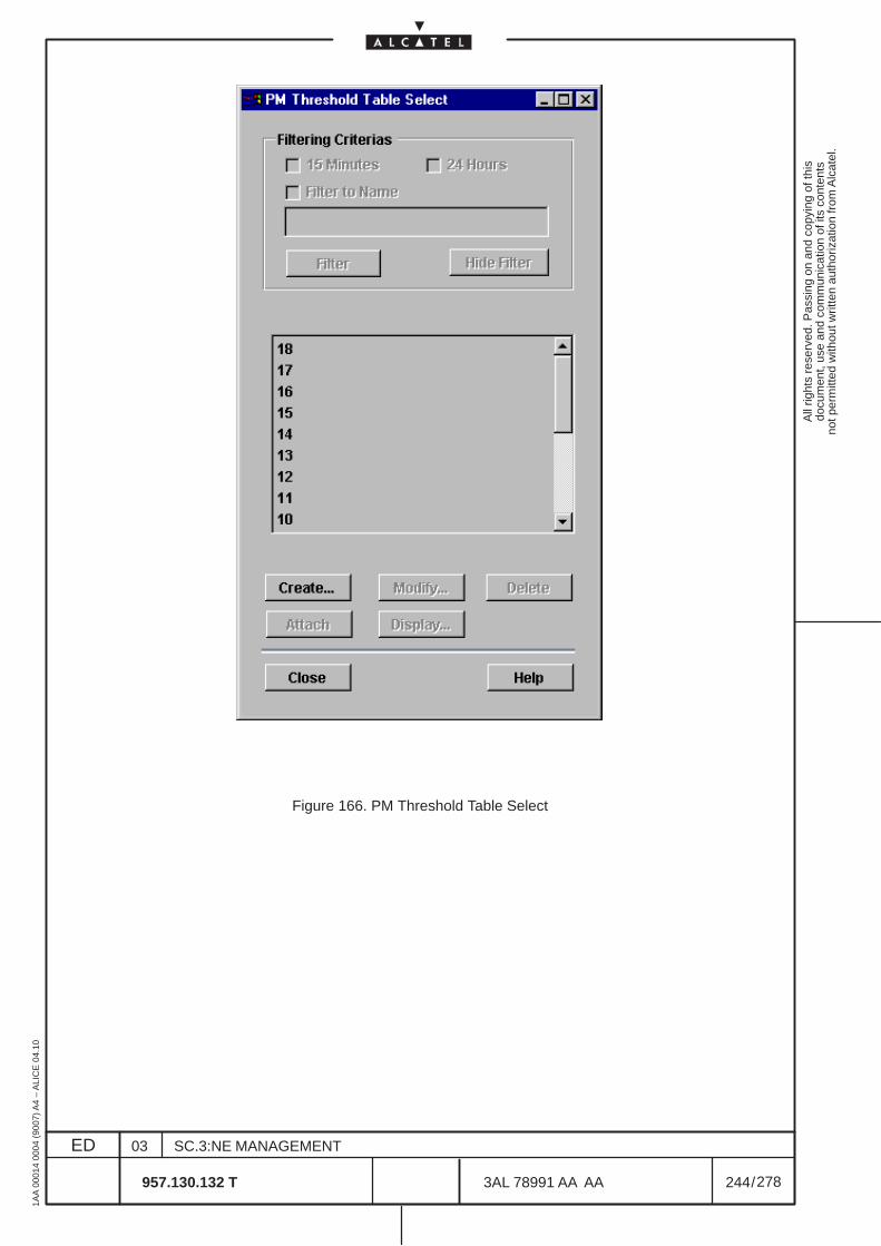
All
right
s re
serv
ed. P
assi
ng o
n an
d co
pyin
g of
this
docu
men
t, us
e an
d co
mm
unic
atio
n of
its
cont
ents
not p
erm
itted
with
out w
ritte
n au
thor
izat
ion
from
Alc
atel
.
ED
1AA
000
14 0
004
(900
7) A
4 –
ALI
CE
04.
10
244
03
957.130.132 T
SC.3:NE MANAGEMENT
/3AL 78991 AA AA
278
278
Figure 166. PM Threshold Table Select
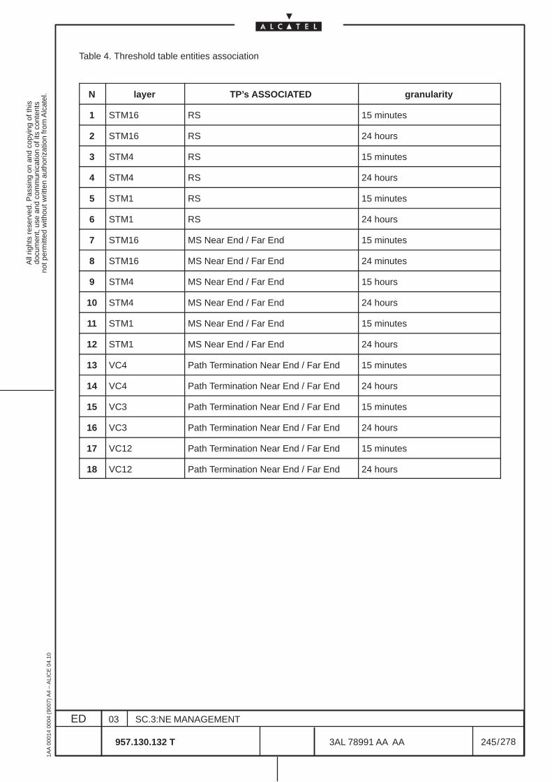
All
right
s re
serv
ed. P
assi
ng o
n an
d co
pyin
g of
this
docu
men
t, us
e an
d co
mm
unic
atio
n of
its
cont
ents
not p
erm
itted
with
out w
ritte
n au
thor
izat
ion
from
Alc
atel
.
ED
1AA
000
14 0
004
(900
7) A
4 –
ALI
CE
04.
10
245
03
957.130.132 T
SC.3:NE MANAGEMENT
/3AL 78991 AA AA
278
278
Table 4. Threshold table entities association
N layer TP’s ASSOCIATED granularity
1 STM16 RS 15 minutes
2 STM16 RS 24 hours
3 STM4 RS 15 minutes
4 STM4 RS 24 hours
5 STM1 RS 15 minutes
6 STM1 RS 24 hours
7 STM16 MS Near End / Far End 15 minutes
8 STM16 MS Near End / Far End 24 minutes
9 STM4 MS Near End / Far End 15 hours
10 STM4 MS Near End / Far End 24 hours
11 STM1 MS Near End / Far End 15 minutes
12 STM1 MS Near End / Far End 24 hours
13 VC4 Path Termination Near End / Far End 15 minutes
14 VC4 Path Termination Near End / Far End 24 hours
15 VC3 Path Termination Near End / Far End 15 minutes
16 VC3 Path Termination Near End / Far End 24 hours
17 VC12 Path Termination Near End / Far End 15 minutes
18 VC12 Path Termination Near End / Far End 24 hours
All
right
s re
serv
ed. P
assi
ng o
n an
d co
pyin
g of
this
docu
men
t, us
e an
d co
mm
unic
atio
n of
its
cont
ents
not p
erm
itted
with
out w
ritte
n au
thor
izat
ion
from
Alc
atel
.
ED
1AA
000
14 0
004
(900
7) A
4 –
ALI
CE
04.
10
246
03
957.130.132 T
SC.3:NE MANAGEMENT
/3AL 78991 AA AA
278
278
17.6 PM Threshold Table Create / Modification / Display
17.6.1 Creation
The PM Threshold Table Create dialog (see Figure 167. on page 247) pops up when the Create buttonis clicked in the PM Threshold Table Selection dialog (see Figure 166. on page 244).
Carry out the following steps to create a threshold table:
1 ) Enter the table name in input field Name.Leading and successing blanks are ignored. Leaving the input field blank or entering only blanksis not allowed and rejected.
2 ) Select a Granularity of 15 min. or 24 h for the entity.
3 ) Enter the upper threshold value (Value Up).Table 5. on page 248 shows the allowed maximum performance parameter values.The lower value (Value Down) is not available in the current release.
4 ) Select the alarm Severity for each PM attribute in case a threshold is crossed.
5 ) Disable Send notification if no notification message should be sent in the case of a crossedthreshold.
6 ) Select the TP type, to which the created threshold table can be attached, in the MonitoredEntity Types list (i.e. a threshold table which only contains, e.g. the entity type “au4CTPBidir”cannot be assigned to a TU-12 CTP):
• Select the relevant entity type in the Supported entity types list on the left.
• Add the selected entity type to the Selected entity types list on the right by clicking on button>>.(Use << to remove an entity type from the list.)
Repeat the procedure to select more entity types.
If no Monitored Entity Type is selected, all entity types are assigned.
7 ) Confirm the entries with Apply to create the threshold table. A number of threshold tables canbe created from the same window.
Explicitly close the window with button Close.
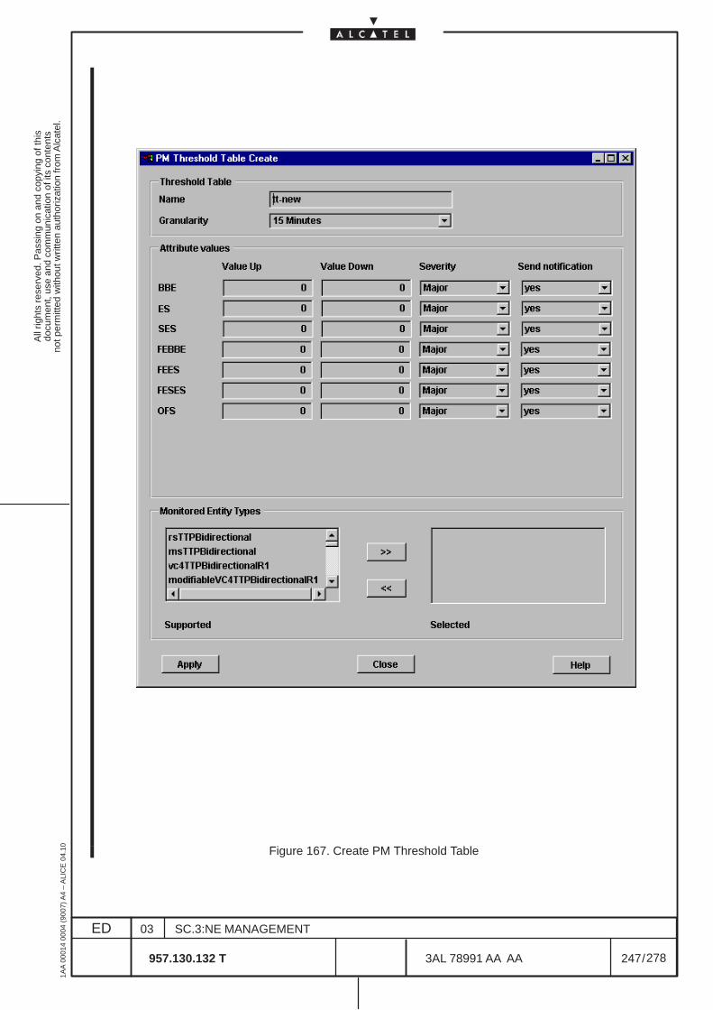
All
right
s re
serv
ed. P
assi
ng o
n an
d co
pyin
g of
this
docu
men
t, us
e an
d co
mm
unic
atio
n of
its
cont
ents
not p
erm
itted
with
out w
ritte
n au
thor
izat
ion
from
Alc
atel
.
ED
1AA
000
14 0
004
(900
7) A
4 –
ALI
CE
04.
10
247
03
957.130.132 T
SC.3:NE MANAGEMENT
/3AL 78991 AA AA
278
278
Figure 167. Create PM Threshold Table
All
right
s re
serv
ed. P
assi
ng o
n an
d co
pyin
g of
this
docu
men
t, us
e an
d co
mm
unic
atio
n of
its
cont
ents
not p
erm
itted
with
out w
ritte
n au
thor
izat
ion
from
Alc
atel
.
ED
1AA
000
14 0
004
(900
7) A
4 –
ALI
CE
04.
10
248
03
957.130.132 T
SC.3:NE MANAGEMENT
/3AL 78991 AA AA
278
278
17.6.2 Modification
The PM Threshold Table Modify dialog (see Figure 168. ) pops up if a threshold table is selected in thePM Threshold Table Selection dialog (see Figure 166. ) and the Modify button is clicked.
Carry out the following steps to modify a threshold table:
1 ) Modify the upper threshold value (Value Up) and the lower value (Value down)
Table 5. shows the allowed maximum performance parameter values.
The lower value (Value Down) is fixed to “0” in the current release .
2 ) Modify the alarm Severity for each PM attribute in case a threshold is crossed.
3 ) Disable Send notification if no notification message should be sent in the case of a crossedthreshold.
Note that the Name (really “number”) cannot be changed.
4 ) Confirm the modifications with Apply.
5 ) To modify more than one threshold table, do not close the dialog, but select the next thresholdtable in the PM Threshold Table Selection dialog and press the Modify button(see Figure 166. ).
Explicitly close the dialog with button Close.
17.6.3 Display
The PM Threshold Table Display dialog (similar to Figure 168. ) pops up if a threshold table is selectedin the PM Threshold Table Selection dialog (see Figure 166. ) and the Display button is clicked.
Refer to the previous chapter for a description of the attribute values and types.
Table 5. Maximum Performance Parameter Values
Performance Parameter Max. Value for 15-min.period
Max. Value for 24-h period
BBE, FEBBE on STM-16 34,559,100 3,317,673,600
BBE, FEBBE on STM-4 8,639,100 829,353,600
BBE, FEBBE on STM-1 2,159,100 207,273,600
BBE, FEBBE 539,100 51,753,600
OFS, ES, UAS, FEES, 900 86,400
SES, FESES 810 78,760
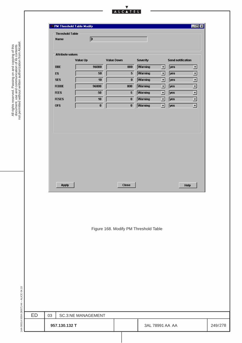
All
right
s re
serv
ed. P
assi
ng o
n an
d co
pyin
g of
this
docu
men
t, us
e an
d co
mm
unic
atio
n of
its
cont
ents
not p
erm
itted
with
out w
ritte
n au
thor
izat
ion
from
Alc
atel
.
ED
1AA
000
14 0
004
(900
7) A
4 –
ALI
CE
04.
10
249
03
957.130.132 T
SC.3:NE MANAGEMENT
/3AL 78991 AA AA
278
278
Figure 168. Modify PM Threshold Table
All
right
s re
serv
ed. P
assi
ng o
n an
d co
pyin
g of
this
docu
men
t, us
e an
d co
mm
unic
atio
n of
its
cont
ents
not p
erm
itted
with
out w
ritte
n au
thor
izat
ion
from
Alc
atel
.
ED
1AA
000
14 0
004
(900
7) A
4 –
ALI
CE
04.
10
250
03
957.130.132 T
SC.3:NE MANAGEMENT
/3AL 78991 AA AA
278
278
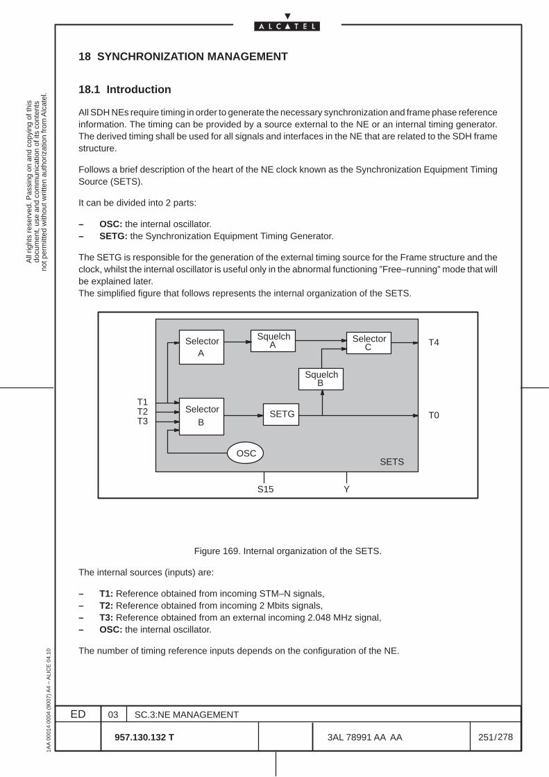
All
right
s re
serv
ed. P
assi
ng o
n an
d co
pyin
g of
this
docu
men
t, us
e an
d co
mm
unic
atio
n of
its
cont
ents
not p
erm
itted
with
out w
ritte
n au
thor
izat
ion
from
Alc
atel
.
ED
1AA
000
14 0
004
(900
7) A
4 –
ALI
CE
04.
10
251
03
957.130.132 T
SC.3:NE MANAGEMENT
/3AL 78991 AA AA
278
278
18 SYNCHRONIZATION MANAGEMENT
18.1 Introduction
All SDH NEs require timing in order to generate the necessary synchronization and frame phase referenceinformation. The timing can be provided by a source external to the NE or an internal timing generator.The derived timing shall be used for all signals and interfaces in the NE that are related to the SDH framestructure.
Follows a brief description of the heart of the NE clock known as the Synchronization Equipment TimingSource (SETS).
It can be divided into 2 parts:
– OSC: the internal oscillator.– SETG: the Synchronization Equipment Timing Generator.
The SETG is responsible for the generation of the external timing source for the Frame structure and theclock, whilst the internal oscillator is useful only in the abnormal functioning ”Free–running” mode that willbe explained later.The simplified figure that follows represents the internal organization of the SETS.
SelectorA
OSC
SETG
SelectorC
SquelchA
SquelchB
T1T2T3
SelectorB
S15 Y
T0
T4
SETS
Figure 169. Internal organization of the SETS.
The internal sources (inputs) are:
– T1: Reference obtained from incoming STM–N signals,– T2: Reference obtained from incoming 2 Mbits signals,– T3: Reference obtained from an external incoming 2.048 MHz signal,– OSC: the internal oscillator.
The number of timing reference inputs depends on the configuration of the NE.
All
right
s re
serv
ed. P
assi
ng o
n an
d co
pyin
g of
this
docu
men
t, us
e an
d co
mm
unic
atio
n of
its
cont
ents
not p
erm
itted
with
out w
ritte
n au
thor
izat
ion
from
Alc
atel
.
ED
1AA
000
14 0
004
(900
7) A
4 –
ALI
CE
04.
10
252
03
957.130.132 T
SC.3:NE MANAGEMENT
/3AL 78991 AA AA
278
278
The external sources (outputs) are:
– T0: is the reference output signal for the clock and signal frames,– T4: is the reference output for the external equipment synchronization.
Other reference points:
– Y: is used for communication of Synchronization Status Message (SSM) between SETS and MSTfunctional blocks.
– S15: is used to provide notifications and loss of incoming timing reference reporting to theSynchronous Equipment Management Function (SEMF).
Selector A provides the capability to select timing reference from available T1 inputs, either automaticallybased on the priority and quality level of the candidate sources (SSM algorithm), or manual as a result ofcommands issued from the managing system.
Selector B is capable of selecting timing reference from T1, T2, or T3 inputs, according to the SSMalgorithm. The capability for manual selection of the timing source is also provided.
Selector C is only operated in manual mode, to switch between SETG output signal (T0) and a T1 timingreference.
The squelch functions A and B mute the relevant timing references in the presence of failure condition,or SSM threshold violation.
The choice of the timing reference is done in two ways:– Automatically:
Following a particular algorithm based on the quality and the priority of the incoming timing signals.The automatic selection is based either on the priority of the incoming timing source (Priorityalgorithm) or on the priority and the quality level of the incoming sources (SSM algorithm).
– Manually:Following an order from the Operator.
N.B. The priority level is determined by the Operator for each candidate timing source. It is staticinformation. On the other hand, the quality of the source is dynamic information, dependantof the quality of the reference clock generating the timing.In an SDH signal frame, the quality of the timing source is located in the Section Overhead.
The SETG has 3 modes of operation:– Locked mode:
The SETG output is fully controlled by the external timing references (T1, T2 and T3).– Hold–Over mode:
The external timing reference is malfunctioning. The SETG during normal functioning storesregularly the value of the external timing reference. In this case the SETG output is controlled by thismemorized value.
– Free running mode:This is not a normal operating mode. The external timing reference and the memorized timingreference are malfunctioning. In this case the SETG output is controlled by the internal clock source.
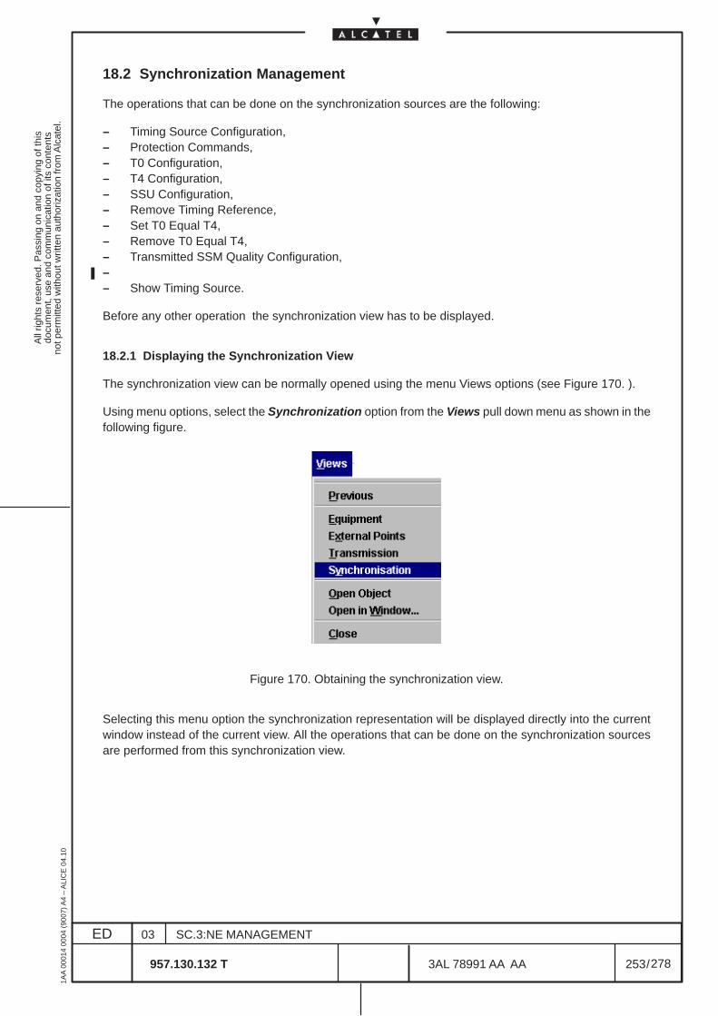
All
right
s re
serv
ed. P
assi
ng o
n an
d co
pyin
g of
this
docu
men
t, us
e an
d co
mm
unic
atio
n of
its
cont
ents
not p
erm
itted
with
out w
ritte
n au
thor
izat
ion
from
Alc
atel
.
ED
1AA
000
14 0
004
(900
7) A
4 –
ALI
CE
04.
10
253
03
957.130.132 T
SC.3:NE MANAGEMENT
/3AL 78991 AA AA
278
278
18.2 Synchronization Management
The operations that can be done on the synchronization sources are the following:
– Timing Source Configuration,– Protection Commands,– T0 Configuration,– T4 Configuration,– SSU Configuration,– Remove Timing Reference,– Set T0 Equal T4,– Remove T0 Equal T4,– Transmitted SSM Quality Configuration,– – Show Timing Source.
Before any other operation the synchronization view has to be displayed.
18.2.1 Displaying the Synchronization View
The synchronization view can be normally opened using the menu Views options (see Figure 170. ).
Using menu options, select the Synchronization option from the Views pull down menu as shown in thefollowing figure.
Figure 170. Obtaining the synchronization view.
Selecting this menu option the synchronization representation will be displayed directly into the currentwindow instead of the current view. All the operations that can be done on the synchronization sourcesare performed from this synchronization view.
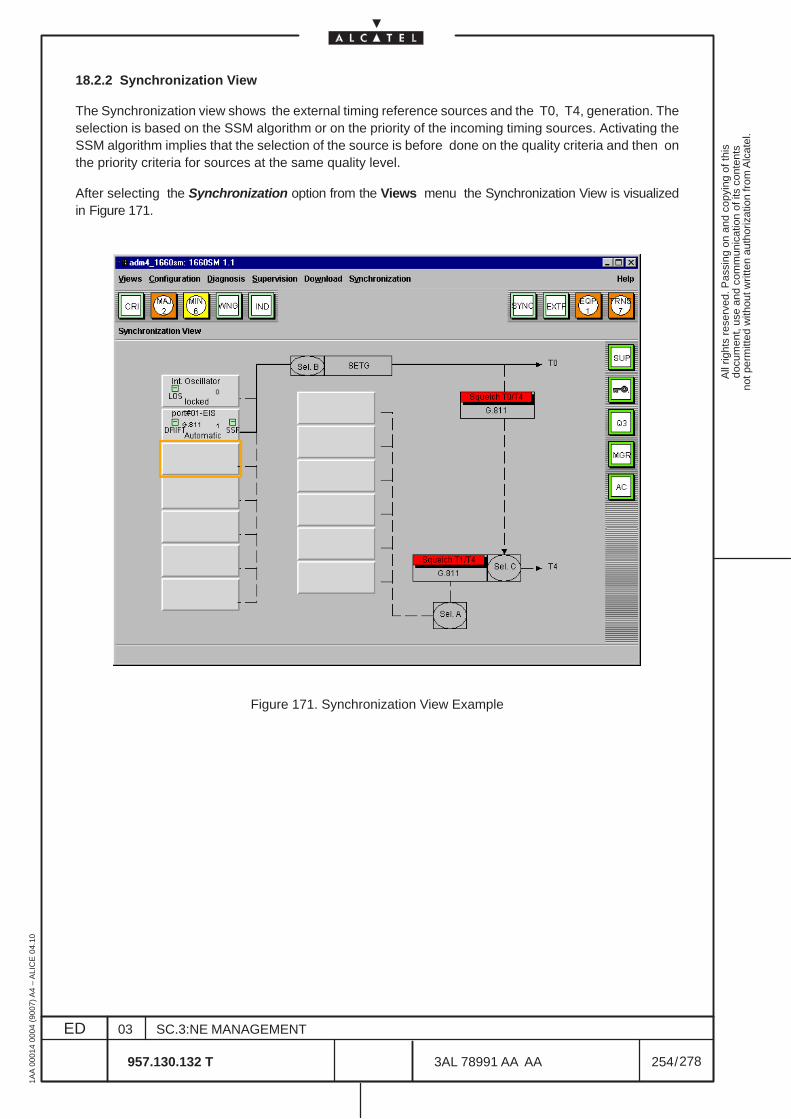
All
right
s re
serv
ed. P
assi
ng o
n an
d co
pyin
g of
this
docu
men
t, us
e an
d co
mm
unic
atio
n of
its
cont
ents
not p
erm
itted
with
out w
ritte
n au
thor
izat
ion
from
Alc
atel
.
ED
1AA
000
14 0
004
(900
7) A
4 –
ALI
CE
04.
10
254
03
957.130.132 T
SC.3:NE MANAGEMENT
/3AL 78991 AA AA
278
278
18.2.2 Synchronization View
The Synchronization view shows the external timing reference sources and the T0, T4, generation. Theselection is based on the SSM algorithm or on the priority of the incoming timing sources. Activating theSSM algorithm implies that the selection of the source is before done on the quality criteria and then onthe priority criteria for sources at the same quality level.
After selecting the Synchronization option from the Views menu the Synchronization View is visualizedin Figure 171.
Figure 171. Synchronization View Example
All
right
s re
serv
ed. P
assi
ng o
n an
d co
pyin
g of
this
docu
men
t, us
e an
d co
mm
unic
atio
n of
its
cont
ents
not p
erm
itted
with
out w
ritte
n au
thor
izat
ion
from
Alc
atel
.
ED
1AA
000
14 0
004
(900
7) A
4 –
ALI
CE
04.
10
255
03
957.130.132 T
SC.3:NE MANAGEMENT
/3AL 78991 AA AA
278
278
Synchronization View Description
The synchronization view provides two list of allowable timing references:
• one for T0 timing output; T0 list is always present;• one for T4 timing output; the presence of the T4 list is configurable using resource files.
T0 list contains :
– a timing reference associated to the Internal Oscillator timing source; it is always presentand it cannot be removed or redefined.
– 6 max timing reference for candidate inputs belonging to the allowable timing referenceT1, T2 or T3 configurable by the operator.
T4 list contains :
– 6 timing reference for candidate inputs belonging to the allowable timing reference T1 con-figurable by the operator.
The T0 and T4 lists are used for the management of reference timing source protection; a 1:n protectionlike mechanism is used for the selection of the timing source from T0 (T4) list of the allowable timing refer-ences, . The protection system chooses the timing reference to generate the output T0 (T4) either auto-matically, basing on the priority and quality level of the candidate sources according a selection algorithmor manually under control of the managing system.
View elements description
Here after, the basic component contained in the synchronization view are described:
• Timing referenceEach allowable timing reference, , is represented by the graphical object displayed in the view;the timing reference graphical object displays (with the exception of Internal Oscillator timingreference) the following information (if the timing source has been declared by the user):
– the name of the selected timing source– the status of the synchronization source: (lockout, manual switch, force switch, automatic
switch, no request, failure)– the label of the quality level of the timing input source– the priority of the timing input source– 2 small boxes representing the SSF (Los) and DRIFT alarms detected on the timing
source;DRIFT means that the Frequency Offset between the external signal source and the inter-nal clock is high then the maximum tolerance value.SSF means that the Server Signal Failure is sending a wrong reference signal to the NE.In case of alarm indication the operator can select Show Timing Source ( Figure 182. )to visualize the alarm detail.
All
right
s re
serv
ed. P
assi
ng o
n an
d co
pyin
g of
this
docu
men
t, us
e an
d co
mm
unic
atio
n of
its
cont
ents
not p
erm
itted
with
out w
ritte
n au
thor
izat
ion
from
Alc
atel
.
ED
1AA
000
14 0
004
(900
7) A
4 –
ALI
CE
04.
10
256
03
957.130.132 T
SC.3:NE MANAGEMENT
/3AL 78991 AA AA
278
278
In the timing reference graphical object associated to the Internal Oscillator the following infor-mation are displayed :
– the name of the timing source: Internal Oscillator– a small box representing the LOS alarm; the small box will be lighted up when all the selec-
ted timing source are lost, indicating the Holdover or Free Running operation mode;– a label field representing the abnormal clock operation modes; one of the following strings
can be displayed in the label field:• Holdover, displayed when the clock operates in Holdover mode;• Free Running, displayed when the clock operates in Free Running mode• empty string is displayed when the clock operates in Lock
– a label ”0” representing the priority of the Internal Oscillator
• Selectorssmall ellipse are used to represent respectively:– the selector A;– the selector B;– the selector C;
• Squelch Statusboxes contained a label field are used to represent the squelch statuses T0/T4 and T4. The boxdis plays the configured quality level threshold and it is lighted up when the output timing signalis inhibited.
• Output Signalan arrow and a label field are used to represent respectively:– the output signal T0;– he output signal T4;
• line Typethe following different line type are used to link the output signals and the respective allowabletiming reference:– A solid line between an output signal and an allowable timing reference means that timing
reference is currently used to generate that signal;– A dashed line between an output signal and an allowable timing reference means that tim-
ing reference is not currently in use as timing source but will act in the protecting role.In the same way, a solid line between T0 signal and T4 signal (or T0_Test signal) box is drawnwhen T0 signal is used to generate T4.
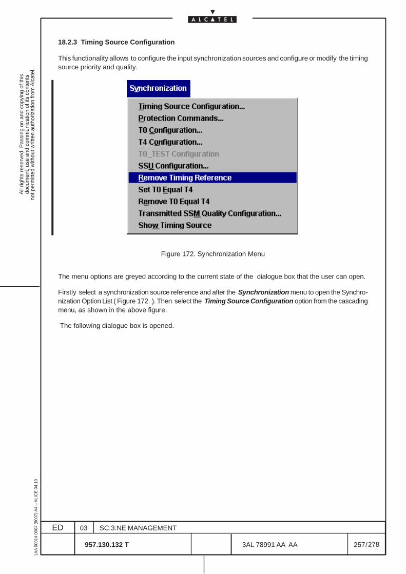
All
right
s re
serv
ed. P
assi
ng o
n an
d co
pyin
g of
this
docu
men
t, us
e an
d co
mm
unic
atio
n of
its
cont
ents
not p
erm
itted
with
out w
ritte
n au
thor
izat
ion
from
Alc
atel
.
ED
1AA
000
14 0
004
(900
7) A
4 –
ALI
CE
04.
10
257
03
957.130.132 T
SC.3:NE MANAGEMENT
/3AL 78991 AA AA
278
278
18.2.3 Timing Source Configuration
This functionality allows to configure the input synchronization sources and configure or modify the timingsource priority and quality.
Figure 172. Synchronization Menu
The menu options are greyed according to the current state of the dialogue box that the user can open.
Firstly select a synchronization source reference and after the Synchronization menu to open the Synchro-nization Option List ( Figure 172. ). Then select the Timing Source Configuration option from the cascadingmenu, as shown in the above figure.
The following dialogue box is opened.
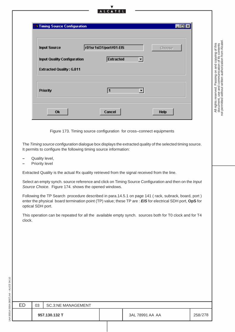
All
right
s re
serv
ed. P
assi
ng o
n an
d co
pyin
g of
this
docu
men
t, us
e an
d co
mm
unic
atio
n of
its
cont
ents
not p
erm
itted
with
out w
ritte
n au
thor
izat
ion
from
Alc
atel
.
ED
1AA
000
14 0
004
(900
7) A
4 –
ALI
CE
04.
10
258
03
957.130.132 T
SC.3:NE MANAGEMENT
/3AL 78991 AA AA
278
278
Figure 173. Timing source configuration for cross–connect equipments
The Timing source configuration dialogue box displays the extracted quality of the selected timing source.It permits to configure the following timing source information:
– Quality level,– Priority level
Extracted Quality is the actual Rx quality retrieved from the signal received from the line.
Select an empty synch. source reference and click on Timing Source Configuration and then on the InputSource Choice. Figure 174. shows the opened windows.
Following the TP Search procedure described in para.14.5.1 on page 141 ( rack, subrack, board, port )enter the physical board termination point (TP) value; these TP are : EIS for electrical SDH port, OpS foroptical SDH port.
This operation can be repeated for all the available empty synch. sources both for T0 clock and for T4clock.
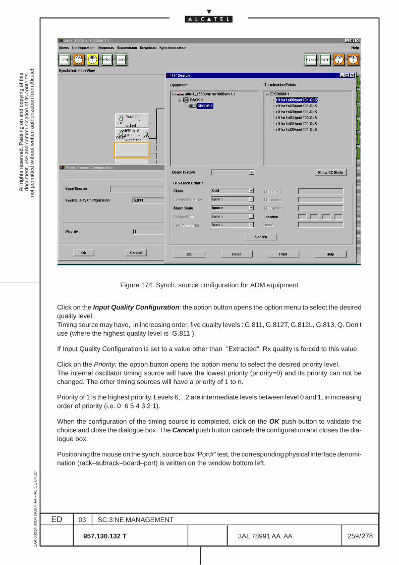
All
right
s re
serv
ed. P
assi
ng o
n an
d co
pyin
g of
this
docu
men
t, us
e an
d co
mm
unic
atio
n of
its
cont
ents
not p
erm
itted
with
out w
ritte
n au
thor
izat
ion
from
Alc
atel
.
ED
1AA
000
14 0
004
(900
7) A
4 –
ALI
CE
04.
10
259
03
957.130.132 T
SC.3:NE MANAGEMENT
/3AL 78991 AA AA
278
278
Figure 174. Synch. source configuration for ADM equipment
Click on the Input Quality Configuration: the option button opens the option menu to select the desiredquality level.Timing source may have, in increasing order, five quality levels : G.811, G.812T, G.812L, G.813, Q. Don’tuse (where the highest quality level is G.811 ).
If Input Quality Configuration is set to a value other than ”Extracted”, Rx quality is forced to this value.
Click on the Priority: the option button opens the option menu to select the desired priority level.The internal oscillator timing source will have the lowest priority (priority=0) and its priority can not bechanged. The other timing sources will have a priority of 1 to n.
Priority of 1 is the highest priority. Levels 6,...2 are intermediate levels between level 0 and 1, in increasingorder of priority (i.e. 0 6 5 4 3 2 1).
When the configuration of the timing source is completed, click on the OK push button to validate thechoice and close the dialogue box. The Cancel push button cancels the configuration and closes the dia-logue box.
Positioning the mouse on the synch. source box “Port#” test, the corresponding physical interface denomi-nation (rack–subrack–board–port) is written on the window bottom left.
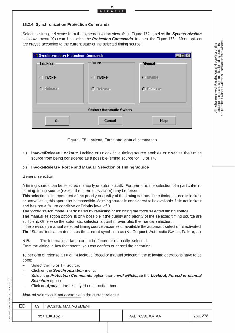
All
right
s re
serv
ed. P
assi
ng o
n an
d co
pyin
g of
this
docu
men
t, us
e an
d co
mm
unic
atio
n of
its
cont
ents
not p
erm
itted
with
out w
ritte
n au
thor
izat
ion
from
Alc
atel
.
ED
1AA
000
14 0
004
(900
7) A
4 –
ALI
CE
04.
10
260
03
957.130.132 T
SC.3:NE MANAGEMENT
/3AL 78991 AA AA
278
278
18.2.4 Synchronization Protection Commands
Select the timing reference from the synchronization view. As in Figure 172. , select the Synchronizationpull down menu. You can then select the Protection Commands to open the Figure 175. Menu optionsare greyed according to the current state of the selected timing source.
Figure 175. Lockout, Force and Manual commands
a ) Invoke/Release Lockout: Locking or unlocking a timing source enables or disables the timingsource from being considered as a possible timing source for T0 or T4.
b ) Invoke/Release Force and Manual Selection of Timing Source
General selection
A timing source can be selected manually or automatically. Furthermore, the selection of a particular in-coming timing source (except the internal oscillator) may be forced.This selection is independent of the priority or quality of the timing source. If the timing source is lockoutor unavailable, this operation is impossible. A timing source is considered to be available if it is not lockoutand has not a failure condition or Priority level of 0.The forced switch mode is terminated by releasing or inhibiting the force selected timing source.The manual selection option is only possible if the quality and priority of the selected timing source aresufficient. Otherwise the automatic selection algorithm overrules the manual selection.If the previously manual selected timing source becomes unavailable the automatic selection is activated.The “Status” indication describes the current synch. status (No Request, Automatic Switch, Failure, ...)
N.B. The internal oscillator cannot be forced or manually selected.From the dialogue box that opens, you can confirm or cancel the operation.
To perform or release a T0 or T4 lockout, forced or manual selection, the following operations have to bedone:– Select the T0 or T4 source.– Click on the Synchronization menu.– Select the Protection Commands option then invoke/Release the Lockout, Forced or manual
Selection option.– Click on Apply in the displayed confirmation box.
Manual selection is not operative in the current release.
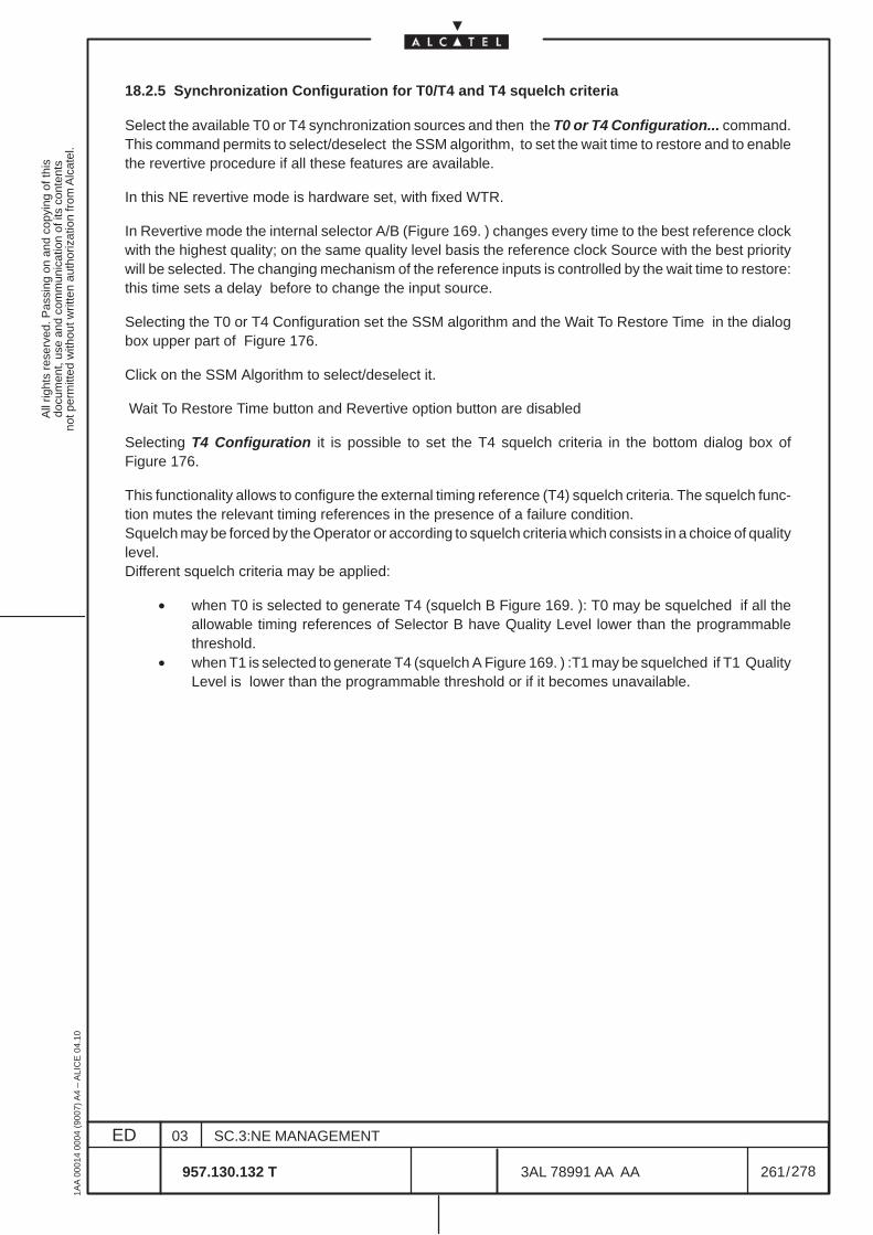
All
right
s re
serv
ed. P
assi
ng o
n an
d co
pyin
g of
this
docu
men
t, us
e an
d co
mm
unic
atio
n of
its
cont
ents
not p
erm
itted
with
out w
ritte
n au
thor
izat
ion
from
Alc
atel
.
ED
1AA
000
14 0
004
(900
7) A
4 –
ALI
CE
04.
10
261
03
957.130.132 T
SC.3:NE MANAGEMENT
/3AL 78991 AA AA
278
278
18.2.5 Synchronization Configuration for T0/T4 and T4 squelch criteria
Select the available T0 or T4 synchronization sources and then the T0 or T4 Configuration... command.This command permits to select/deselect the SSM algorithm, to set the wait time to restore and to enablethe revertive procedure if all these features are available.
In this NE revertive mode is hardware set, with fixed WTR.
In Revertive mode the internal selector A/B (Figure 169. ) changes every time to the best reference clockwith the highest quality; on the same quality level basis the reference clock Source with the best prioritywill be selected. The changing mechanism of the reference inputs is controlled by the wait time to restore:this time sets a delay before to change the input source.
Selecting the T0 or T4 Configuration set the SSM algorithm and the Wait To Restore Time in the dialogbox upper part of Figure 176.
Click on the SSM Algorithm to select/deselect it.
Wait To Restore Time button and Revertive option button are disabled
Selecting T4 Configuration it is possible to set the T4 squelch criteria in the bottom dialog box ofFigure 176.
This functionality allows to configure the external timing reference (T4) squelch criteria. The squelch func-tion mutes the relevant timing references in the presence of a failure condition.Squelch may be forced by the Operator or according to squelch criteria which consists in a choice of qualitylevel.Different squelch criteria may be applied:
• when T0 is selected to generate T4 (squelch B Figure 169. ): T0 may be squelched if all theallowable timing references of Selector B have Quality Level lower than the programmablethreshold.
• when T1 is selected to generate T4 (squelch A Figure 169. ) :T1 may be squelched if T1 QualityLevel is lower than the programmable threshold or if it becomes unavailable.
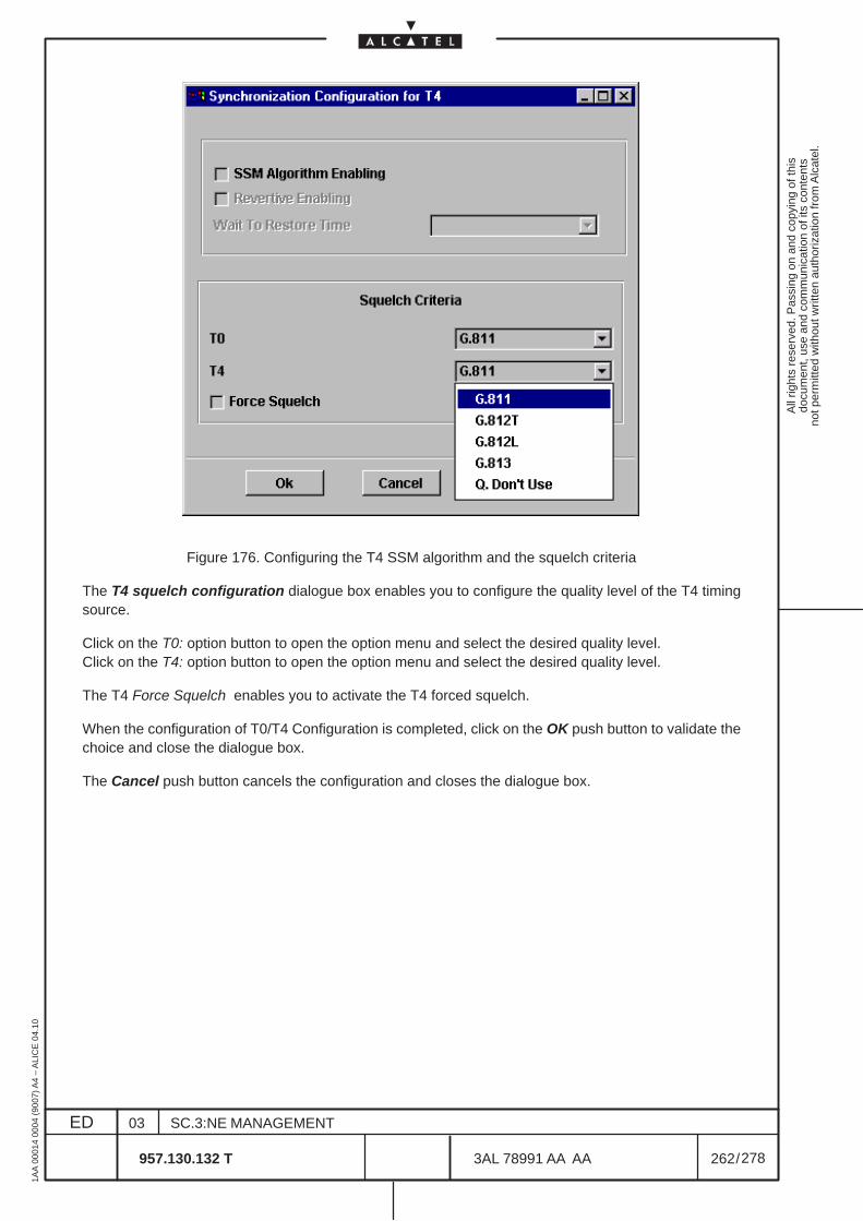
All
right
s re
serv
ed. P
assi
ng o
n an
d co
pyin
g of
this
docu
men
t, us
e an
d co
mm
unic
atio
n of
its
cont
ents
not p
erm
itted
with
out w
ritte
n au
thor
izat
ion
from
Alc
atel
.
ED
1AA
000
14 0
004
(900
7) A
4 –
ALI
CE
04.
10
262
03
957.130.132 T
SC.3:NE MANAGEMENT
/3AL 78991 AA AA
278
278
Figure 176. Configuring the T4 SSM algorithm and the squelch criteria
The T4 squelch configuration dialogue box enables you to configure the quality level of the T4 timingsource.
Click on the T0: option button to open the option menu and select the desired quality level.Click on the T4: option button to open the option menu and select the desired quality level.
The T4 Force Squelch enables you to activate the T4 forced squelch.
When the configuration of T0/T4 Configuration is completed, click on the OK push button to validate thechoice and close the dialogue box.
The Cancel push button cancels the configuration and closes the dialogue box.
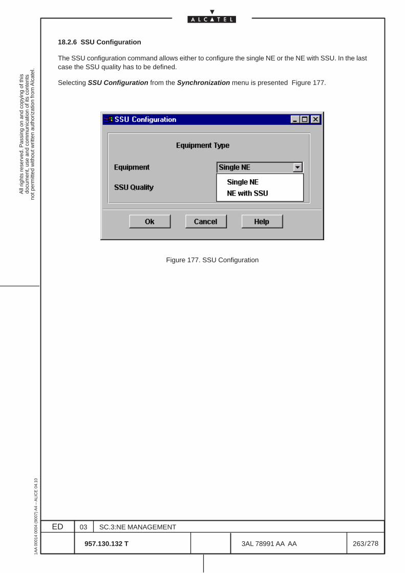
All
right
s re
serv
ed. P
assi
ng o
n an
d co
pyin
g of
this
docu
men
t, us
e an
d co
mm
unic
atio
n of
its
cont
ents
not p
erm
itted
with
out w
ritte
n au
thor
izat
ion
from
Alc
atel
.
ED
1AA
000
14 0
004
(900
7) A
4 –
ALI
CE
04.
10
263
03
957.130.132 T
SC.3:NE MANAGEMENT
/3AL 78991 AA AA
278
278
18.2.6 SSU Configuration
The SSU configuration command allows either to configure the single NE or the NE with SSU. In the lastcase the SSU quality has to be defined.
Selecting SSU Configuration from the Synchronization menu is presented Figure 177.
Figure 177. SSU Configuration
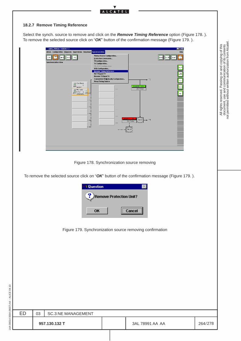
All
right
s re
serv
ed. P
assi
ng o
n an
d co
pyin
g of
this
docu
men
t, us
e an
d co
mm
unic
atio
n of
its
cont
ents
not p
erm
itted
with
out w
ritte
n au
thor
izat
ion
from
Alc
atel
.
ED
1AA
000
14 0
004
(900
7) A
4 –
ALI
CE
04.
10
264
03
957.130.132 T
SC.3:NE MANAGEMENT
/3AL 78991 AA AA
278
278
18.2.7 Remove Timing Reference
Select the synch. source to remove and click on the Remove Timing Reference option (Figure 178. ).To remove the selected source click on “OK” button of the confirmation message (Figure 179. ).
Figure 178. Synchronization source removing
To remove the selected source click on “OK” button of the confirmation message (Figure 179. ).
Figure 179. Synchronization source removing confirmation
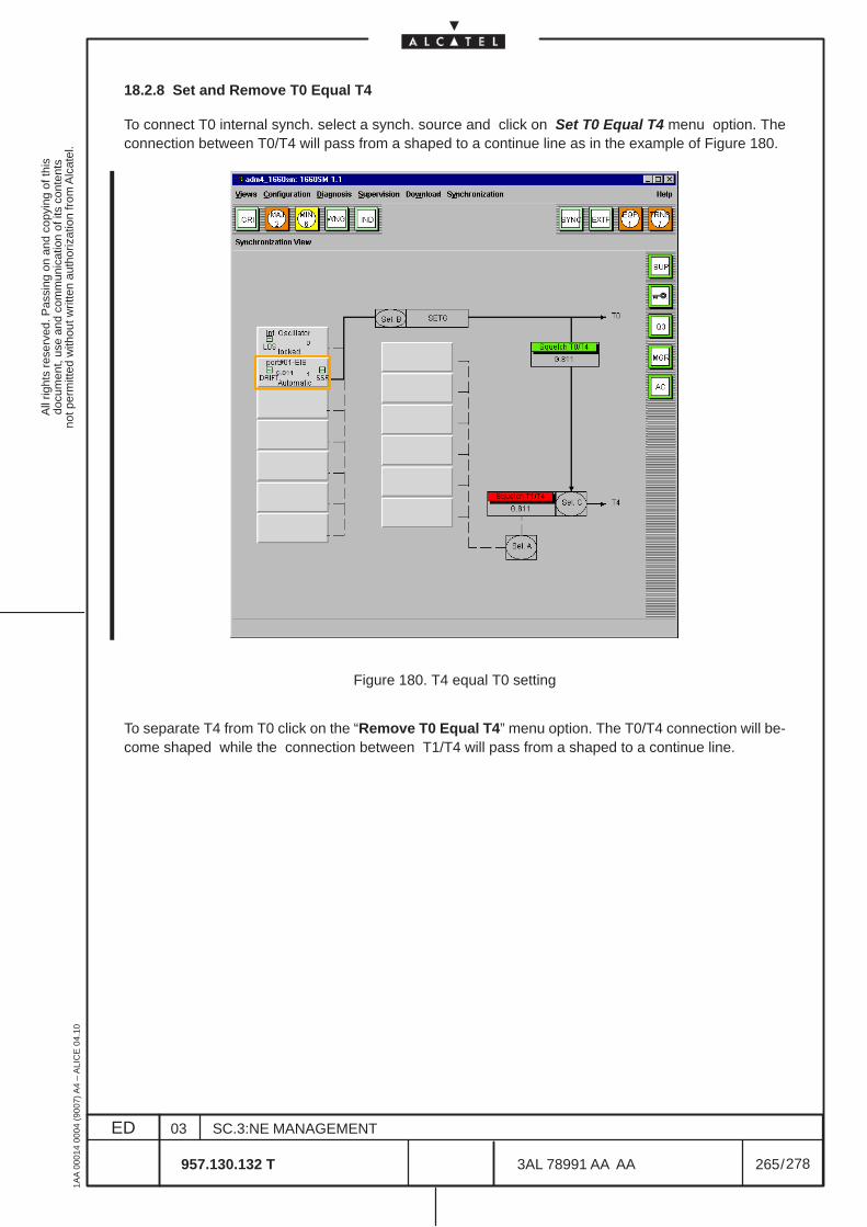
All
right
s re
serv
ed. P
assi
ng o
n an
d co
pyin
g of
this
docu
men
t, us
e an
d co
mm
unic
atio
n of
its
cont
ents
not p
erm
itted
with
out w
ritte
n au
thor
izat
ion
from
Alc
atel
.
ED
1AA
000
14 0
004
(900
7) A
4 –
ALI
CE
04.
10
265
03
957.130.132 T
SC.3:NE MANAGEMENT
/3AL 78991 AA AA
278
278
18.2.8 Set and Remove T0 Equal T4
To connect T0 internal synch. select a synch. source and click on Set T0 Equal T4 menu option. Theconnection between T0/T4 will pass from a shaped to a continue line as in the example of Figure 180.
Figure 180. T4 equal T0 setting
To separate T4 from T0 click on the “Remove T0 Equal T4” menu option. The T0/T4 connection will be-come shaped while the connection between T1/T4 will pass from a shaped to a continue line.
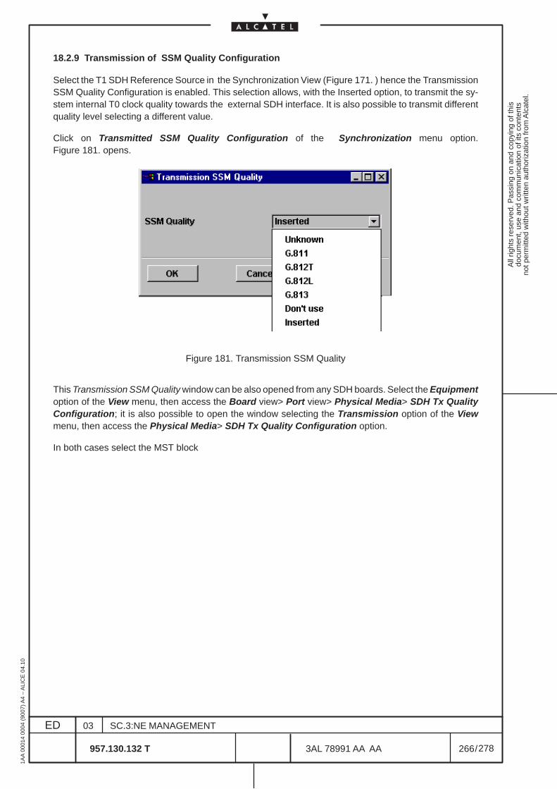
All
right
s re
serv
ed. P
assi
ng o
n an
d co
pyin
g of
this
docu
men
t, us
e an
d co
mm
unic
atio
n of
its
cont
ents
not p
erm
itted
with
out w
ritte
n au
thor
izat
ion
from
Alc
atel
.
ED
1AA
000
14 0
004
(900
7) A
4 –
ALI
CE
04.
10
266
03
957.130.132 T
SC.3:NE MANAGEMENT
/3AL 78991 AA AA
278
278
18.2.9 Transmission of SSM Quality Configuration
Select the T1 SDH Reference Source in the Synchronization View (Figure 171. ) hence the TransmissionSSM Quality Configuration is enabled. This selection allows, with the Inserted option, to transmit the sy-stem internal T0 clock quality towards the external SDH interface. It is also possible to transmit differentquality level selecting a different value.
Click on Transmitted SSM Quality Configuration of the Synchronization menu option.Figure 181. opens.
Figure 181. Transmission SSM Quality
This Transmission SSM Quality window can be also opened from any SDH boards. Select the Equipmentoption of the View menu, then access the Board view> Port view> Physical Media> SDH Tx QualityConfiguration; it is also possible to open the window selecting the Transmission option of the Viewmenu, then access the Physical Media> SDH Tx Quality Configuration option.
In both cases select the MST block
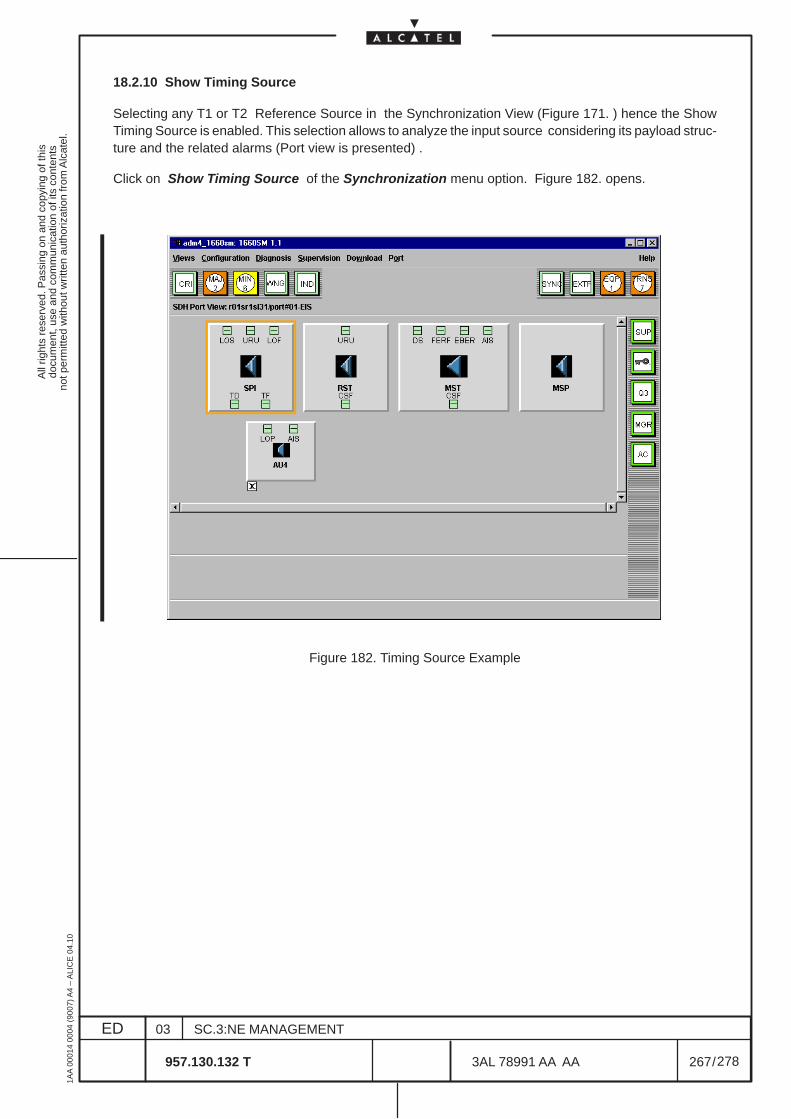
All
right
s re
serv
ed. P
assi
ng o
n an
d co
pyin
g of
this
docu
men
t, us
e an
d co
mm
unic
atio
n of
its
cont
ents
not p
erm
itted
with
out w
ritte
n au
thor
izat
ion
from
Alc
atel
.
ED
1AA
000
14 0
004
(900
7) A
4 –
ALI
CE
04.
10
267
03
957.130.132 T
SC.3:NE MANAGEMENT
/3AL 78991 AA AA
278
278
18.2.10 Show Timing Source
Selecting any T1 or T2 Reference Source in the Synchronization View (Figure 171. ) hence the ShowTiming Source is enabled. This selection allows to analyze the input source considering its payload struc-ture and the related alarms (Port view is presented) .
Click on Show Timing Source of the Synchronization menu option. Figure 182. opens.
Figure 182. Timing Source Example

All
right
s re
serv
ed. P
assi
ng o
n an
d co
pyin
g of
this
docu
men
t, us
e an
d co
mm
unic
atio
n of
its
cont
ents
not p
erm
itted
with
out w
ritte
n au
thor
izat
ion
from
Alc
atel
.
ED
1AA
000
14 0
004
(900
7) A
4 –
ALI
CE
04.
10
268
03
957.130.132 T
SC.3:NE MANAGEMENT
/3AL 78991 AA AA
278
278
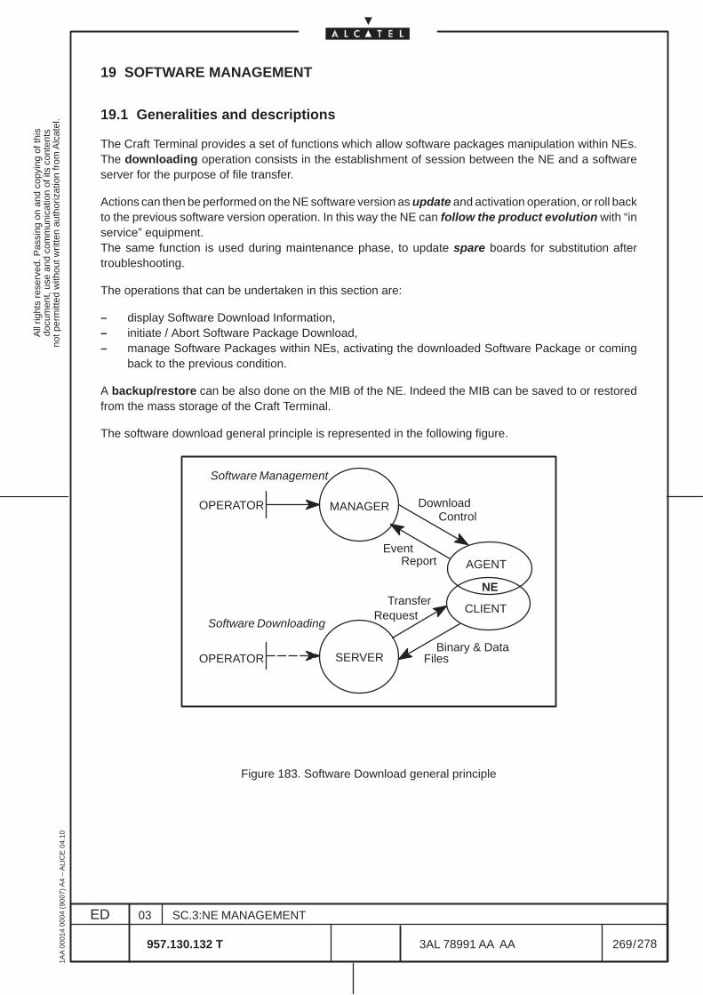
All
right
s re
serv
ed. P
assi
ng o
n an
d co
pyin
g of
this
docu
men
t, us
e an
d co
mm
unic
atio
n of
its
cont
ents
not p
erm
itted
with
out w
ritte
n au
thor
izat
ion
from
Alc
atel
.
ED
1AA
000
14 0
004
(900
7) A
4 –
ALI
CE
04.
10
269
03
957.130.132 T
SC.3:NE MANAGEMENT
/3AL 78991 AA AA
278
278
19 SOFTWARE MANAGEMENT
19.1 Generalities and descriptions
The Craft Terminal provides a set of functions which allow software packages manipulation within NEs.The downloading operation consists in the establishment of session between the NE and a softwareserver for the purpose of file transfer.
Actions can then be performed on the NE software version as update and activation operation, or roll backto the previous software version operation. In this way the NE can follow the product evolution with “inservice” equipment.The same function is used during maintenance phase, to update spare boards for substitution aftertroubleshooting.
The operations that can be undertaken in this section are:
– display Software Download Information,– initiate / Abort Software Package Download,– manage Software Packages within NEs, activating the downloaded Software Package or coming
back to the previous condition.
A backup/restore can be also done on the MIB of the NE. Indeed the MIB can be saved to or restoredfrom the mass storage of the Craft Terminal.
The software download general principle is represented in the following figure.
MANAGER
SERVER
CLIENT
AGENT
NE
DownloadControl
EventReport
TransferRequest
Binary & DataFiles
Software Management
Software Downloading
OPERATOR
OPERATOR
Figure 183. Software Download general principle
All
right
s re
serv
ed. P
assi
ng o
n an
d co
pyin
g of
this
docu
men
t, us
e an
d co
mm
unic
atio
n of
its
cont
ents
not p
erm
itted
with
out w
ritte
n au
thor
izat
ion
from
Alc
atel
.
ED
1AA
000
14 0
004
(900
7) A
4 –
ALI
CE
04.
10
270
03
957.130.132 T
SC.3:NE MANAGEMENT
/3AL 78991 AA AA
278
278
19.1.1 Naming Conventions
The naming conventions used for Download Management are the following:
– Software Package: Software Package stands for a piece of software which can be executed by anNE of a particular type. It consists in one or more Software Units and a Descriptor File. A softwarepackage is identified by its name, release, version and edition.On the NE (i.e. once downloaded) a software package can be:
– the active version: the software package currently running on the NE– a standby version: a software package which is neither the active version nor the boot
version
– Software Unit: A Software Unit is a part of a software package which can be either executable codeor a data segment of a particular board within an NE. A software unit is also identified by its name,release, version and edition.
– Descriptor File: A Descriptor File contains information about the software package it belongs to andlists the composing software units. Each software package must have a descriptor file otherwise itwould not be possible to interpret the content of the package.
– Software Management Function: The Software management function offers information about allcurrent software packages present in an NE. Indicators enable software management (runningpackage, activated package, etc...).
The following software version states are available:• Commit (active) version: the software version currently running on the NE.• Standby version: is a software version which has been downloaded on the NE but which is
not in the active state.
Two main functions are involved in the software downloading:– Software Download Manager function– Software Download Server function
The Software Download Manager function takes the downloading and management requests of theoperator and sends them to the NE. Thus, this function enables a download process to be initiated andmonitored by the operator. It manages the NE software releases and initiates software downloadoperations.
The Software Download Server is only responsible for fulfilling the requests received from NEs andperforming software package file transfer operations to the NE.
All
right
s re
serv
ed. P
assi
ng o
n an
d co
pyin
g of
this
docu
men
t, us
e an
d co
mm
unic
atio
n of
its
cont
ents
not p
erm
itted
with
out w
ritte
n au
thor
izat
ion
from
Alc
atel
.
ED
1AA
000
14 0
004
(900
7) A
4 –
ALI
CE
04.
10
271
03
957.130.132 T
SC.3:NE MANAGEMENT
/3AL 78991 AA AA
278
278
19.2 Software download operative sequence
Two main different operative condition are defined for this Equipment:
• First installation of a 1660SMThe NE is received without the relevant software install. The software download must be doneas described in the SIBDL section of this Handbook.
• Updating a 1660SM with an already installed software.Follow the operative indications of para. 19.2.1 on page 271 .
19.2.1 Software Download upgrade
N.B. In order to migrate from Release 1.1A to a Higher Release, the download procedure requirestwo steps. The first is from 1.1A to 1.1X (intermediate package) and the second is from 1.1Xto the Higher Release (e.g. 1.1B1).
In order to update the following procedure is to be done as explained in the next steps:
a ) Install the CD ROM with the NE Software Package on the PC, as for the procedure of para 19.2.2on page 272.
b ) open a session on Craft Terminal application (start–up of the application, start supervision and NElogin)
c ) Check the present status of the software on a selected NE.
Download should not be performed in presence of unstable alarms
d ) Open the Download menu as for para. 19.3 on page 273.
e ) Select the new software package in the server and triggers the download process, as presented atpara.19.4 on page 274.A message will indicate the completed download.
f ) Activate the package as presented at para.19.5 on page 276.
g ) Check that the activated package is in the “Commit” status.
h ) If problems are found with the new activated package, activate the previous software package (re-vert–back operation) to come back to the previous condition and then try to repeat the procedure.
All
right
s re
serv
ed. P
assi
ng o
n an
d co
pyin
g of
this
docu
men
t, us
e an
d co
mm
unic
atio
n of
its
cont
ents
not p
erm
itted
with
out w
ritte
n au
thor
izat
ion
from
Alc
atel
.
ED
1AA
000
14 0
004
(900
7) A
4 –
ALI
CE
04.
10
272
03
957.130.132 T
SC.3:NE MANAGEMENT
/3AL 78991 AA AA
278
278
19.2.2 NE Software package installation procedure
Before to begin the software download choose one of this two procedure:
1 ) Install from CD ROM the NE Software Package on the Personal Computer, as explained in the“1320CT Basic Operator Handbook”.
Run the “Sotware Administration” menu from Network Equipment Synthesis, as explained in the1320CT Basic Operator’s Handbook.
In the window that opens select the directory where the NE software package file has been installed( tipically is Alcatel/usm/ect/swdw/<equipment name>/<version>/<descriptor file> ) and execute.
2 ) Simply insert the CD ROM in the drive of the Personal Computer.
Run the “Software Administration” menu from NES as explained in the 1320CT Basic Operator’sHandbook.
Select the NE software package file directly from the CD ROM and execute (tipically ect/swdw/<equipment name>/<version>/ <descriptor file>
At this point the NE Software Package is installed in another directory and available to be downloaded asexplained from para. 19.3 on page 273.
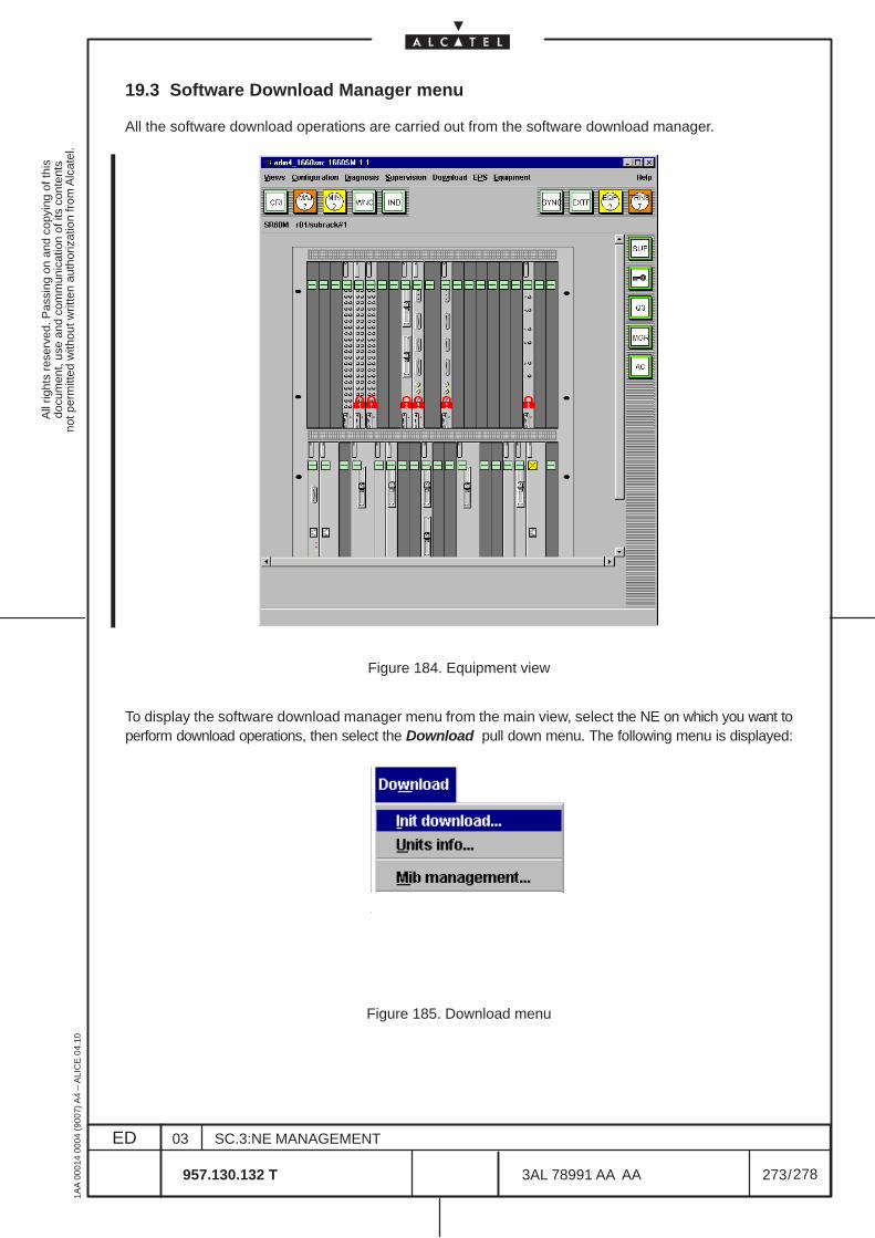
All
right
s re
serv
ed. P
assi
ng o
n an
d co
pyin
g of
this
docu
men
t, us
e an
d co
mm
unic
atio
n of
its
cont
ents
not p
erm
itted
with
out w
ritte
n au
thor
izat
ion
from
Alc
atel
.
ED
1AA
000
14 0
004
(900
7) A
4 –
ALI
CE
04.
10
273
03
957.130.132 T
SC.3:NE MANAGEMENT
/3AL 78991 AA AA
278
278
19.3 Software Download Manager menu
All the software download operations are carried out from the software download manager.
Figure 184. Equipment view
To display the software download manager menu from the main view, select the NE on which you want toperform download operations, then select the Download pull down menu. The following menu is displayed:
Figure 185. Download menu
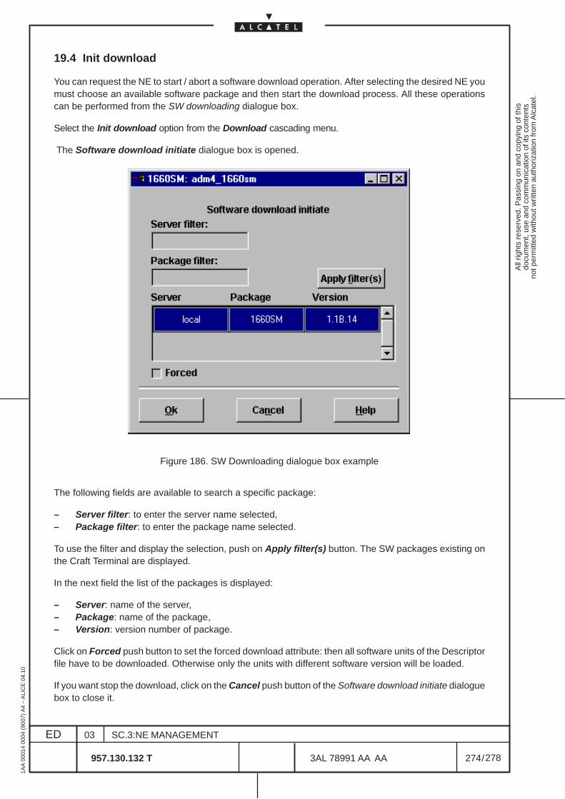
All
right
s re
serv
ed. P
assi
ng o
n an
d co
pyin
g of
this
docu
men
t, us
e an
d co
mm
unic
atio
n of
its
cont
ents
not p
erm
itted
with
out w
ritte
n au
thor
izat
ion
from
Alc
atel
.
ED
1AA
000
14 0
004
(900
7) A
4 –
ALI
CE
04.
10
274
03
957.130.132 T
SC.3:NE MANAGEMENT
/3AL 78991 AA AA
278
278
19.4 Init download
You can request the NE to start / abort a software download operation. After selecting the desired NE youmust choose an available software package and then start the download process. All these operationscan be performed from the SW downloading dialogue box.
Select the Init download option from the Download cascading menu.
The Software download initiate dialogue box is opened.
Figure 186. SW Downloading dialogue box example
The following fields are available to search a specific package:
– Server filter: to enter the server name selected,– Package filter: to enter the package name selected.
To use the filter and display the selection, push on Apply filter(s) button. The SW packages existing onthe Craft Terminal are displayed.
In the next field the list of the packages is displayed:
– Server: name of the server,– Package: name of the package,– Version: version number of package.
Click on Forced push button to set the forced download attribute: then all software units of the Descriptorfile have to be downloaded. Otherwise only the units with different software version will be loaded.
If you want stop the download, click on the Cancel push button of the Software download initiate dialoguebox to close it.
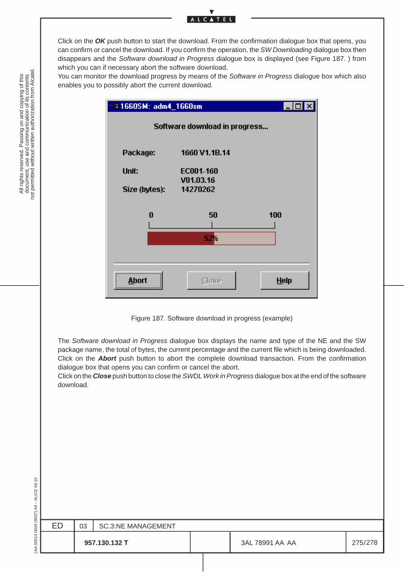
All
right
s re
serv
ed. P
assi
ng o
n an
d co
pyin
g of
this
docu
men
t, us
e an
d co
mm
unic
atio
n of
its
cont
ents
not p
erm
itted
with
out w
ritte
n au
thor
izat
ion
from
Alc
atel
.
ED
1AA
000
14 0
004
(900
7) A
4 –
ALI
CE
04.
10
275
03
957.130.132 T
SC.3:NE MANAGEMENT
/3AL 78991 AA AA
278
278
Click on the OK push button to start the download. From the confirmation dialogue box that opens, youcan confirm or cancel the download. If you confirm the operation, the SW Downloading dialogue box thendisappears and the Software download in Progress dialogue box is displayed (see Figure 187. ) fromwhich you can if necessary abort the software download.You can monitor the download progress by means of the Software in Progress dialogue box which alsoenables you to possibly abort the current download.
Figure 187. Software download in progress (example)
The Software download in Progress dialogue box displays the name and type of the NE and the SWpackage name, the total of bytes, the current percentage and the current file which is being downloaded.Click on the Abort push button to abort the complete download transaction. From the confirmationdialogue box that opens you can confirm or cancel the abort.Click on the Close push button to close the SWDL Work in Progress dialogue box at the end of the softwaredownload.
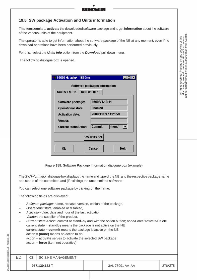
All
right
s re
serv
ed. P
assi
ng o
n an
d co
pyin
g of
this
docu
men
t, us
e an
d co
mm
unic
atio
n of
its
cont
ents
not p
erm
itted
with
out w
ritte
n au
thor
izat
ion
from
Alc
atel
.
ED
1AA
000
14 0
004
(900
7) A
4 –
ALI
CE
04.
10
276
03
957.130.132 T
SC.3:NE MANAGEMENT
/3AL 78991 AA AA
278
278
19.5 SW package Activation and Units information
This item permits to activate the downloaded software package and to get information about the softwareof the various units of the equipment.
The operator is able to get information about the software package of the NE at any moment, even if nodownload operations have been performed previously.
For this, select the Units info option from the Download pull down menu.
The following dialogue box is opened.
Figure 188. Software Package Information dialogue box (example)
The SW Information dialogue box displays the name and type of the NE, and the respective package nameand status of the committed and (if existing) the uncommitted software.
You can select one software package by clicking on the name.
The following fields are displayed:
– Software package: name, release, version, edition of the package,– Operational state: enabled or disabled,– Activation date: date and hour of the last activation– Vendor: the supplier of the product,– Current state\Action: commit or stand–by and with the option button; none/Force/Activate/Delete
current state = standby means the package is not active on the NEcurrent state = commit means the package is active on the NEaction = (none) means no action to doaction = activate serves to activate the selected SW packageaction = force (item not operative)
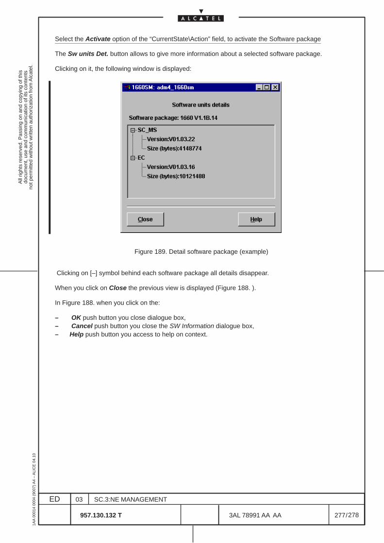
All
right
s re
serv
ed. P
assi
ng o
n an
d co
pyin
g of
this
docu
men
t, us
e an
d co
mm
unic
atio
n of
its
cont
ents
not p
erm
itted
with
out w
ritte
n au
thor
izat
ion
from
Alc
atel
.
ED
1AA
000
14 0
004
(900
7) A
4 –
ALI
CE
04.
10
277
03
957.130.132 T
SC.3:NE MANAGEMENT
/3AL 78991 AA AA
278
278
Select the Activate option of the “CurrentState\Action” field, to activate the Software package
The Sw units Det. button allows to give more information about a selected software package.
Clicking on it, the following window is displayed:
Figure 189. Detail software package (example)
Clicking on [–] symbol behind each software package all details disappear.
When you click on Close the previous view is displayed (Figure 188. ).
In Figure 188. when you click on the:
– OK push button you close dialogue box,– Cancel push button you close the SW Information dialogue box,– Help push button you access to help on context.
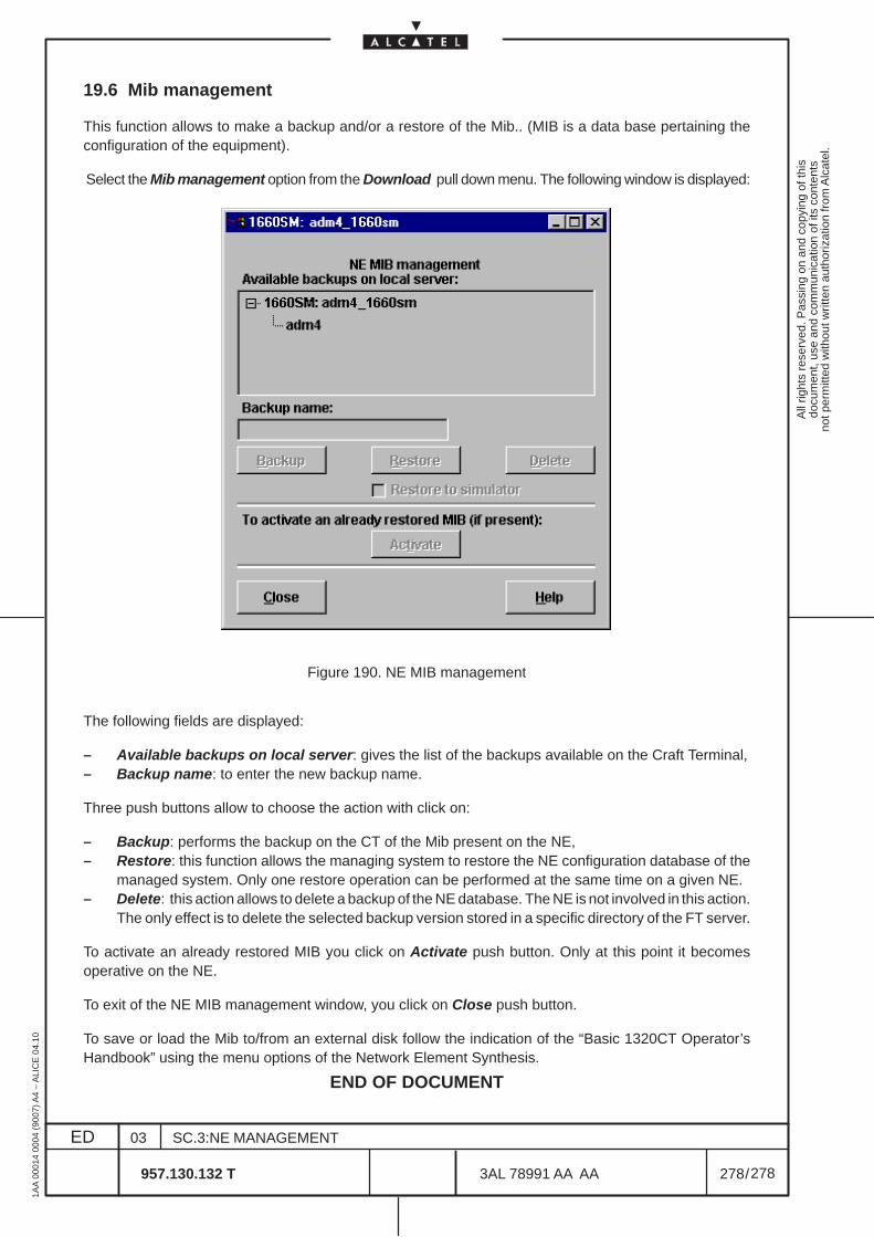
All
right
s re
serv
ed. P
assi
ng o
n an
d co
pyin
g of
this
docu
men
t, us
e an
d co
mm
unic
atio
n of
its
cont
ents
not p
erm
itted
with
out w
ritte
n au
thor
izat
ion
from
Alc
atel
.
ED
1AA
000
14 0
004
(900
7) A
4 –
ALI
CE
04.
10
278
03
957.130.132 T
SC.3:NE MANAGEMENT
/3AL 78991 AA AA
278
278
19.6 Mib management
This function allows to make a backup and/or a restore of the Mib.. (MIB is a data base pertaining theconfiguration of the equipment).
Select the Mib management option from the Download pull down menu. The following window is displayed:
Figure 190. NE MIB management
The following fields are displayed:
– Available backups on local server: gives the list of the backups available on the Craft Terminal,– Backup name: to enter the new backup name.
Three push buttons allow to choose the action with click on:
– Backup: performs the backup on the CT of the Mib present on the NE,– Restore: this function allows the managing system to restore the NE configuration database of the
managed system. Only one restore operation can be performed at the same time on a given NE.– Delete: this action allows to delete a backup of the NE database. The NE is not involved in this action.
The only effect is to delete the selected backup version stored in a specific directory of the FT server.
To activate an already restored MIB you click on Activate push button. Only at this point it becomesoperative on the NE.
To exit of the NE MIB management window, you click on Close push button.
To save or load the Mib to/from an external disk follow the indication of the “Basic 1320CT Operator’sHandbook” using the menu options of the Network Element Synthesis.
END OF DOCUMENT
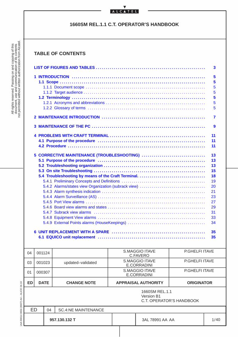
All
right
s re
serv
ed. P
assi
ng o
n an
d co
pyin
g of
this
docu
men
t, us
e an
d co
mm
unic
atio
n of
its
cont
ents
not p
erm
itted
with
out w
ritte
n au
thor
izat
ion
from
Alc
atel
.
ED
1AA
000
14 0
004
(900
7) A
4 –
ALI
CE
04.
10
1
04
957.130.132 T
SC.4:NE MAINTENANCE
/3AL 78991 AA AA
40
40
1660SM REL.1.1 C.T. OPERATOR’S HANDBOOK
TABLE OF CONTENTS
LIST OF FIGURES AND TABLES 3. . . . . . . . . . . . . . . . . . . . . . . . . . . . . . . . . . . . . . . . . . . . . . . . . . . . . . .
1 INTRODUCTION 5. . . . . . . . . . . . . . . . . . . . . . . . . . . . . . . . . . . . . . . . . . . . . . . . . . . . . . . . . . . . . . . . . . . 1.1 Scope 5. . . . . . . . . . . . . . . . . . . . . . . . . . . . . . . . . . . . . . . . . . . . . . . . . . . . . . . . . . . . . . . . . . . . . . . . .
1.1.1 Document scope 5. . . . . . . . . . . . . . . . . . . . . . . . . . . . . . . . . . . . . . . . . . . . . . . . . . . . . . . . . . . . 1.1.2 Target audience 5. . . . . . . . . . . . . . . . . . . . . . . . . . . . . . . . . . . . . . . . . . . . . . . . . . . . . . . . . . . . .
1.2 Terminology 5. . . . . . . . . . . . . . . . . . . . . . . . . . . . . . . . . . . . . . . . . . . . . . . . . . . . . . . . . . . . . . . . . . . 1.2.1 Acronyms and abbreviations 5. . . . . . . . . . . . . . . . . . . . . . . . . . . . . . . . . . . . . . . . . . . . . . . . . . 1.2.2 Glossary of terms 5. . . . . . . . . . . . . . . . . . . . . . . . . . . . . . . . . . . . . . . . . . . . . . . . . . . . . . . . . . .
2 MAINTENANCE INTRODUCTION 7. . . . . . . . . . . . . . . . . . . . . . . . . . . . . . . . . . . . . . . . . . . . . . . . . . . .
3 MAINTENANCE OF THE PC 9. . . . . . . . . . . . . . . . . . . . . . . . . . . . . . . . . . . . . . . . . . . . . . . . . . . . . . . . .
4 PROBLEMS WITH CRAFT TERMINAL 11. . . . . . . . . . . . . . . . . . . . . . . . . . . . . . . . . . . . . . . . . . . . . . . . 4.1 Purpose of the procedure 11. . . . . . . . . . . . . . . . . . . . . . . . . . . . . . . . . . . . . . . . . . . . . . . . . . . . . . 4.2 Procedure 11. . . . . . . . . . . . . . . . . . . . . . . . . . . . . . . . . . . . . . . . . . . . . . . . . . . . . . . . . . . . . . . . . . . . .
5 CORRECTIVE MAINTENANCE (TROUBLESHOOTING) 13. . . . . . . . . . . . . . . . . . . . . . . . . . . . . . . . 5.1 Purpose of the procedure 13. . . . . . . . . . . . . . . . . . . . . . . . . . . . . . . . . . . . . . . . . . . . . . . . . . . . . . 5.2 Troubleshooting organization 13. . . . . . . . . . . . . . . . . . . . . . . . . . . . . . . . . . . . . . . . . . . . . . . . . . . 5.3 On site Troubleshooting 15. . . . . . . . . . . . . . . . . . . . . . . . . . . . . . . . . . . . . . . . . . . . . . . . . . . . . . . . 5.4 Troubleshooting by means of the Craft Terminal. 18. . . . . . . . . . . . . . . . . . . . . . . . . . . . . . . . .
5.4.1 Preliminary Concepts and Definitions 19. . . . . . . . . . . . . . . . . . . . . . . . . . . . . . . . . . . . . . . . . . 5.4.2 Alarms/states view Organization (subrack view) 20. . . . . . . . . . . . . . . . . . . . . . . . . . . . . . . . . 5.4.3 Alarm synthesis indication 21. . . . . . . . . . . . . . . . . . . . . . . . . . . . . . . . . . . . . . . . . . . . . . . . . . . . 5.4.4 Alarm Surveillance (AS) 23. . . . . . . . . . . . . . . . . . . . . . . . . . . . . . . . . . . . . . . . . . . . . . . . . . . . . . 5.4.5 Port View alarms 27. . . . . . . . . . . . . . . . . . . . . . . . . . . . . . . . . . . . . . . . . . . . . . . . . . . . . . . . . . . . 5.4.6 Board view alarms and states 29. . . . . . . . . . . . . . . . . . . . . . . . . . . . . . . . . . . . . . . . . . . . . . . . . 5.4.7 Subrack view alarms 31. . . . . . . . . . . . . . . . . . . . . . . . . . . . . . . . . . . . . . . . . . . . . . . . . . . . . . . . 5.4.8 Equipment View alarms 33. . . . . . . . . . . . . . . . . . . . . . . . . . . . . . . . . . . . . . . . . . . . . . . . . . . . . . 5.4.9 External Points alarms (HouseKeepings) 34. . . . . . . . . . . . . . . . . . . . . . . . . . . . . . . . . . . . . . .
6 UNIT REPLACEMENT WITH A SPARE 35. . . . . . . . . . . . . . . . . . . . . . . . . . . . . . . . . . . . . . . . . . . . . . . 6.1 EQUICO unit replacement 35. . . . . . . . . . . . . . . . . . . . . . . . . . . . . . . . . . . . . . . . . . . . . . . . . . . . . .
ED DATE CHANGE NOTE APPRAISAL AUTHORITY ORIGINATOR
01 000307 S.MAGGIO ITAVE P.GHELFI ITAVE
03 001023 updated–validated S.MAGGIO ITAVE P.GHELFI ITAVE
00112404 S.MAGGIO ITAVE P.GHELFI ITAVE
1660SM REL.1.1Version B1C.T. OPERATOR’S HANDBOOK
E.CORRADINI
E.CORRADINI
C.FAVERO
All
right
s re
serv
ed. P
assi
ng o
n an
d co
pyin
g of
this
docu
men
t, us
e an
d co
mm
unic
atio
n of
its
cont
ents
not p
erm
itted
with
out w
ritte
n au
thor
izat
ion
from
Alc
atel
.
ED
1AA
000
14 0
004
(900
7) A
4 –
ALI
CE
04.
10
2
04
957.130.132 T
SC.4:NE MAINTENANCE
/3AL 78991 AA AA
40
40
7 UPGRADING WITH NEW HARDWARE 37. . . . . . . . . . . . . . . . . . . . . . . . . . . . . . . . . . . . . . . . . . . . . . . 7.1 MATRIX substitution with MATRIXN 38. . . . . . . . . . . . . . . . . . . . . . . . . . . . . . . . . . . . . . . . . . . . . 7.2 P4S1, S–41, L–41, L–42, S–161, L–161, L–162 substitution with P4S1N, S–41N, L–41N,L–42N , S–161N, L–161N, L–162N 39. . . . . . . . . . . . . . . . . . . . . . . . . . . . . . . . . . . . . . . . . . . . . . . . . . .
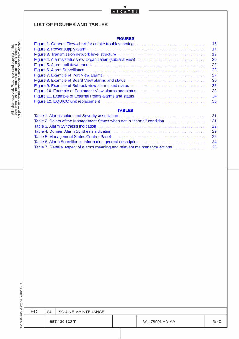
All
right
s re
serv
ed. P
assi
ng o
n an
d co
pyin
g of
this
docu
men
t, us
e an
d co
mm
unic
atio
n of
its
cont
ents
not p
erm
itted
with
out w
ritte
n au
thor
izat
ion
from
Alc
atel
.
ED
1AA
000
14 0
004
(900
7) A
4 –
ALI
CE
04.
10
3
04
957.130.132 T
SC.4:NE MAINTENANCE
/3AL 78991 AA AA
40
40
LIST OF FIGURES AND TABLES
FIGURESFigure 1. General Flow–chart for on site troubleshooting 16. . . . . . . . . . . . . . . . . . . . . . . . . . . . . . . . . . . Figure 2. Power supply alarm 17. . . . . . . . . . . . . . . . . . . . . . . . . . . . . . . . . . . . . . . . . . . . . . . . . . . . . . . . . . . Figure 3. Transmission network level structure 19. . . . . . . . . . . . . . . . . . . . . . . . . . . . . . . . . . . . . . . . . . . . Figure 4. Alarms/status view Organization (subrack view) 20. . . . . . . . . . . . . . . . . . . . . . . . . . . . . . . . . . . Figure 5. Alarm pull down menu. 23. . . . . . . . . . . . . . . . . . . . . . . . . . . . . . . . . . . . . . . . . . . . . . . . . . . . . . . . Figure 6. Alarm Surveillance 23. . . . . . . . . . . . . . . . . . . . . . . . . . . . . . . . . . . . . . . . . . . . . . . . . . . . . . . . . . . . Figure 7. Example of Port View alarms 27. . . . . . . . . . . . . . . . . . . . . . . . . . . . . . . . . . . . . . . . . . . . . . . . . . . Figure 8. Example of Board View alarms and status 30. . . . . . . . . . . . . . . . . . . . . . . . . . . . . . . . . . . . . . . Figure 9. Example of Subrack view alarms and status 32. . . . . . . . . . . . . . . . . . . . . . . . . . . . . . . . . . . . . . Figure 10. Example of Equipment View alarms and status 33. . . . . . . . . . . . . . . . . . . . . . . . . . . . . . . . . . Figure 11. Example of External Points alarms and status 34. . . . . . . . . . . . . . . . . . . . . . . . . . . . . . . . . . . Figure 12. EQUICO unit replacement 36. . . . . . . . . . . . . . . . . . . . . . . . . . . . . . . . . . . . . . . . . . . . . . . . . . . .
TABLESTable 1. Alarms colors and Severity association 21. . . . . . . . . . . . . . . . . . . . . . . . . . . . . . . . . . . . . . . . . . . Table 2. Colors of the Management States when not in “normal” condition 21. . . . . . . . . . . . . . . . . . . . Table 3. Alarm Synthesis indication 22. . . . . . . . . . . . . . . . . . . . . . . . . . . . . . . . . . . . . . . . . . . . . . . . . . . . . . Table 4. Domain Alarm Synthesis indication 22. . . . . . . . . . . . . . . . . . . . . . . . . . . . . . . . . . . . . . . . . . . . . . Table 5. Management States Control Panel. 22. . . . . . . . . . . . . . . . . . . . . . . . . . . . . . . . . . . . . . . . . . . . . . Table 6. Alarm Surveillance information general description 24. . . . . . . . . . . . . . . . . . . . . . . . . . . . . . . . . Table 7. General aspect of alarms meaning and relevant maintenance actions 25. . . . . . . . . . . . . . . .

All
right
s re
serv
ed. P
assi
ng o
n an
d co
pyin
g of
this
docu
men
t, us
e an
d co
mm
unic
atio
n of
its
cont
ents
not p
erm
itted
with
out w
ritte
n au
thor
izat
ion
from
Alc
atel
.
ED
1AA
000
14 0
004
(900
7) A
4 –
ALI
CE
04.
10
4
04
957.130.132 T
SC.4:NE MAINTENANCE
/3AL 78991 AA AA
40
40
All
right
s re
serv
ed. P
assi
ng o
n an
d co
pyin
g of
this
docu
men
t, us
e an
d co
mm
unic
atio
n of
its
cont
ents
not p
erm
itted
with
out w
ritte
n au
thor
izat
ion
from
Alc
atel
.
ED
1AA
000
14 0
004
(900
7) A
4 –
ALI
CE
04.
10
5
04
957.130.132 T
SC.4:NE MAINTENANCE
/3AL 78991 AA AA
40
40
1 INTRODUCTION
1.1 Scope
1.1.1 Document scope
The Maintenance Manual mainly describes the NE troubleshooting with Craft Terminal.
1.1.2 Target audience
The Maintenance Manual is intended for all users.
The documents that should be read before starting this document are:
– 1320CT Rel. 1.1 Basic Operator’s Handbook
The documents of this Handbook that should be read before starting this document are:
– Introduction manual
– NE Management manual
1.2 Terminology
1.2.1 Acronyms and abbreviations
Refer to the Section Introduction manual.
1.2.2 Glossary of terms
Refer to the Section Introduction manual.

All
right
s re
serv
ed. P
assi
ng o
n an
d co
pyin
g of
this
docu
men
t, us
e an
d co
mm
unic
atio
n of
its
cont
ents
not p
erm
itted
with
out w
ritte
n au
thor
izat
ion
from
Alc
atel
.
ED
1AA
000
14 0
004
(900
7) A
4 –
ALI
CE
04.
10
6
04
957.130.132 T
SC.4:NE MAINTENANCE
/3AL 78991 AA AA
40
40
All
right
s re
serv
ed. P
assi
ng o
n an
d co
pyin
g of
this
docu
men
t, us
e an
d co
mm
unic
atio
n of
its
cont
ents
not p
erm
itted
with
out w
ritte
n au
thor
izat
ion
from
Alc
atel
.
ED
1AA
000
14 0
004
(900
7) A
4 –
ALI
CE
04.
10
7
04
957.130.132 T
SC.4:NE MAINTENANCE
/3AL 78991 AA AA
40
40
2 MAINTENANCE INTRODUCTION
The maintenance procedures consist of the following steps:
– Maintenance of the PC. See Chapter 3 on page 9
– Problems with Craft terminal (shut–down and restart of the PC). See Chapter 4 on page 11.
– Corrective Maintenance (Troubleshooting). See Chapter 5 on page 13.
– Unit replacement with a spare. See Chapter 6 on page 35.

All
right
s re
serv
ed. P
assi
ng o
n an
d co
pyin
g of
this
docu
men
t, us
e an
d co
mm
unic
atio
n of
its
cont
ents
not p
erm
itted
with
out w
ritte
n au
thor
izat
ion
from
Alc
atel
.
ED
1AA
000
14 0
004
(900
7) A
4 –
ALI
CE
04.
10
8
04
957.130.132 T
SC.4:NE MAINTENANCE
/3AL 78991 AA AA
40
40

All
right
s re
serv
ed. P
assi
ng o
n an
d co
pyin
g of
this
docu
men
t, us
e an
d co
mm
unic
atio
n of
its
cont
ents
not p
erm
itted
with
out w
ritte
n au
thor
izat
ion
from
Alc
atel
.
ED
1AA
000
14 0
004
(900
7) A
4 –
ALI
CE
04.
10
9
04
957.130.132 T
SC.4:NE MAINTENANCE
/3AL 78991 AA AA
40
40
3 MAINTENANCE OF THE PC
With regard to maintenance PC, refer to the constructor’s documentation.

All
right
s re
serv
ed. P
assi
ng o
n an
d co
pyin
g of
this
docu
men
t, us
e an
d co
mm
unic
atio
n of
its
cont
ents
not p
erm
itted
with
out w
ritte
n au
thor
izat
ion
from
Alc
atel
.
ED
1AA
000
14 0
004
(900
7) A
4 –
ALI
CE
04.
10
10
04
957.130.132 T
SC.4:NE MAINTENANCE
/3AL 78991 AA AA
40
40

All
right
s re
serv
ed. P
assi
ng o
n an
d co
pyin
g of
this
docu
men
t, us
e an
d co
mm
unic
atio
n of
its
cont
ents
not p
erm
itted
with
out w
ritte
n au
thor
izat
ion
from
Alc
atel
.
ED
1AA
000
14 0
004
(900
7) A
4 –
ALI
CE
04.
10
11
04
957.130.132 T
SC.4:NE MAINTENANCE
/3AL 78991 AA AA
40
40
4 PROBLEMS WITH CRAFT TERMINAL
4.1 Purpose of the procedure
This procedure describes the Shut–down and restart the PC should the Craft Terminal SoftWare Productnot be working properly or not responding to the operator’s commands.
4.2 Procedure
In order to shut down the PC execute the command :
Start > Shut down
A window (Windows NT Security user dialog) is displayed. It permits to shut down the computer or restartit.
The same window is displayed pressing he keys <Ctrl> + <Alt> + <Del> simultaneously.

All
right
s re
serv
ed. P
assi
ng o
n an
d co
pyin
g of
this
docu
men
t, us
e an
d co
mm
unic
atio
n of
its
cont
ents
not p
erm
itted
with
out w
ritte
n au
thor
izat
ion
from
Alc
atel
.
ED
1AA
000
14 0
004
(900
7) A
4 –
ALI
CE
04.
10
12
04
957.130.132 T
SC.4:NE MAINTENANCE
/3AL 78991 AA AA
40
40
All
right
s re
serv
ed. P
assi
ng o
n an
d co
pyin
g of
this
docu
men
t, us
e an
d co
mm
unic
atio
n of
its
cont
ents
not p
erm
itted
with
out w
ritte
n au
thor
izat
ion
from
Alc
atel
.
ED
1AA
000
14 0
004
(900
7) A
4 –
ALI
CE
04.
10
13
04
957.130.132 T
SC.4:NE MAINTENANCE
/3AL 78991 AA AA
40
40
5 CORRECTIVE MAINTENANCE (TROUBLESHOOTING)
5.1 Purpose of the procedure
Troubleshooting involves the detection, location and correction of failures in the equipment and thereplacement of the defective parts.
5.2 Troubleshooting organization
The troubleshooting procedure is carried out with the help of some flow–charts and tables, reportedhereinafter. Anyway this method does not deal with the following aspects (which are to be deduced in otherways):
– faulty electronic alarm indication, processing and detection circuits– faulty wiring (back–panel, connectors, etc.)
The following interfaces are present to troubleshoot the equipment :
• Q3 interface for Telecommunication Management Network• F interface for Craft Terminal (Local or Remote)• Remote Alarm for Supervisory Center• LEDs on the units of the NE
Usually maintenance is firstly done via software (TMN or Remote Craft Terminal) to locate the faultyequipment and the faulty unit or the faulty path and then on site to physically solve the trouble.
The Maintenance can be done :
• from a TMN network management center• from a Remote Craft Terminal (RCT) management center• from a station supervisory center• on site
TMN network management center: by means of the TMN the maintenance technician can see thealarms sent by each equipment of the managed network (see the relevant TMN handbooks).
Remote craft terminal: the operator, connected to a local NE , can remotely manage and troubleshootinga network composed of max 32 NEs included itself. This handbook is used.
Station supervisory center: the maintenance technician refers to the Remote Alarms received from theequipment in a centralized office of the station i.e. :
– T URGENT (MAJOR and CRITICAL), T NOT URGENT (MINOR): remote alarms pertaining to theurgent, not urgent alarm type.
– TOR, TAND: remote alarms respectively due to the decrease or loss of one or both station powersupply DC voltages.
– INT: Remote alarm pertaining to the local (internal) alarm typeWhen a second CONGI unit is used the following remote alarms are added:– TORC, TANC: remote alarms respectively due to the loss of +3,3V generated by the on board
converter in of one or both the CONGI units.– IND: Indeterminate alarm synthesis. Indicates synthesis of alarms not associated to others
severities. Not operative.– TUP: remote alarm due to microprocessor fault in the EQUICO unit– LOSQ2: remote alarm due to loss of communication with Mediation Device. Not operative.
All
right
s re
serv
ed. P
assi
ng o
n an
d co
pyin
g of
this
docu
men
t, us
e an
d co
mm
unic
atio
n of
its
cont
ents
not p
erm
itted
with
out w
ritte
n au
thor
izat
ion
from
Alc
atel
.
ED
1AA
000
14 0
004
(900
7) A
4 –
ALI
CE
04.
10
14
04
957.130.132 T
SC.4:NE MAINTENANCE
/3AL 78991 AA AA
40
40
Depending on the supervisory center organization, it is possible to locate the equipment in troubles andto detect the failure type and source.
On site : the operator is on site in case :
1 ) the equipment is not managed by a TMN or by a Remote Craft terminal (RCT)
2 ) the equipment is not reachable by the remote manager (TMN or RCT) and is therefore isolated
3 ) link problems are present
4 ) the trouble has been located and a substitution is necessary
In case 1 ) , 2 ), 3 ), the alarmed equipment is checked by means of the local Craft Terminal and of rackLED indications and station buzzers.
The NE is provided with LEDs which indicate:
Units Alarms:
Each port card or access card of the equipment is provided with a bicolor LED (green/red) on the frontcoverplate.This LED indicates:– when red, internal failure (indicates that the unit concerned must be replaced)– when green, in service unit
Centralized Equipment Alarms:
All the alarms detected on the units are collected by the EQUICO unit which will deliver centralized opticalindications (by means of LEDs on its front coverplate). Specifically, from the top to the bottom :
• Red LED: detection of an URGENT (MAJOR and CRITICAL) alarm• Red LED: detection of a NOT URGENT (MINOR) alarm• Yellow LED: alarm condition ATTENDED• Yellow LED: detection of an ABNORMAL operative condition. Type: active loopbacks, forcing
the unit into service, laser forced ON or OFF, try to restore after ALS• Yellow LED: detection of an INDICATION (WARNING) alarm
The analysis of these LEDs permits to detect the alarm type (Urgent – Not Urgent – Indication) andrelevant condition (Abnormal condition, Attended).In case of URGENT or NOT URGENT alarm, after having located the alarmed equipment, the alarmcondition can be ”attended” by pressing the relevant alarm storing push button on the EQUICO unit.
This condition causes:
– On the rack
• the YELLOW LED to light up• the RED LED to go off
– On the front coverplate:
• yellow LED (ATTENDED) to light up• red LEDs NOT URGENT (MINOR) and URGENT (MAJOR and CRITICAL) to turn off (free to
accept other alarms)If both LEDs are on, the Attend command should be given twice : one for attending the NOTURGENT (MINOR) alarm and one for attending the URGENT (MAJOR) alarm.
All
right
s re
serv
ed. P
assi
ng o
n an
d co
pyin
g of
this
docu
men
t, us
e an
d co
mm
unic
atio
n of
its
cont
ents
not p
erm
itted
with
out w
ritte
n au
thor
izat
ion
from
Alc
atel
.
ED
1AA
000
14 0
004
(900
7) A
4 –
ALI
CE
04.
10
15
04
957.130.132 T
SC.4:NE MAINTENANCE
/3AL 78991 AA AA
40
40
5.3 On site Troubleshooting
The trouble–shooting operation proceeds according to the information indicated in the flow–charts:
– Figure 1. on page 16: General flow–chart
– Figure 2. on page 17: Power supply alarm
and according to para.5.4 on page 18.
As indicated in the flow–charts the troubleshooting operation is done by means of the Craft Terminal, andof the optical indicators (LEDs) present on the NE.
The Craft Terminal is cord–connected to the relative connector on the EQUICO unit front coverplate (Finterface).
The Craft Terminal applications provide detailed information on the alarm state thus facilitating faultlocation and subsequent removal as indicated in para. 5.4 on page 18.
To correctly execute the troubleshooting operations the technician must know the exactequipment configuration (see Equipment Configuration applications on the Craft Terminal).
The aim of the flow–charts which follow and of the maintenance tables is to locate the faulty unit and toreplace it with a spare as well as to locate a failure along the link.
The flow–charts/tables should be also consulted when the unit LEDs flash, because the flashing conditionmight be due to external alarm causes usually related to line problems.
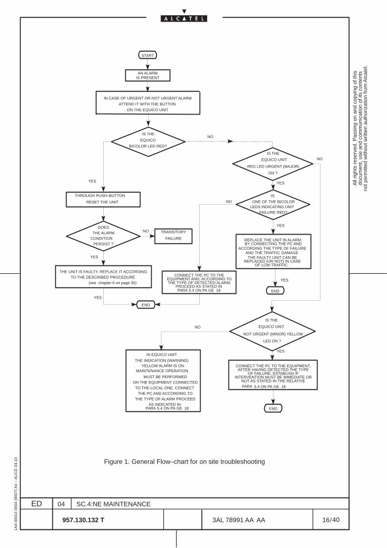
All
right
s re
serv
ed. P
assi
ng o
n an
d co
pyin
g of
this
docu
men
t, us
e an
d co
mm
unic
atio
n of
its
cont
ents
not p
erm
itted
with
out w
ritte
n au
thor
izat
ion
from
Alc
atel
.
ED
1AA
000
14 0
004
(900
7) A
4 –
ALI
CE
04.
10
16
04
957.130.132 T
SC.4:NE MAINTENANCE
/3AL 78991 AA AA
40
40
START
AN ALARMIS PRESENT
IN CASE OF URGENT OR NOT URGENT ALARM
ON THE EQUICO UNIT
IS THE
EQUICO
BICOLOR LED RED?
NO
IS THE
RED LED URGENT (MAJOR)
NO
ON ?
THROUGH PUSH–BUTTON
RESET THE UNIT
DOESTHE ALARM
CONDITIONPERSIST ?
NO TRANSITORY
FAILURE
THE UNIT IS FAULTY. REPLACE IT ACCORDINGTO THE DESCRIBED PROCEDURE
IS
ONE OF THE BICOLORLEDS INDICATING UNIT
FAILURE RED?
NO
YES
REPLACE THE UNIT IN ALARM.BY CONNECTING THE PC AND
ACCORDING THE TYPE OF FAILURE
THE FAULTY UNIT CAN BEREPLACED (OR NOT) IN CASE
OF LOW TRAFFIC .
END
CONNECT THE PC TO THEEQUIPMENT AND, ACCORDING TOTHE TYPE OF DETECTED ALARM,
PROCEED AS STATED IN
END
IS THE
NOT URGENT (MINOR) YELLOW
LED ON ?
NO
YES
CONNECT THE PC TO THE EQUIPMENT,
END
AFTER HAVING DETECTED THE TYPEOF FAILURE, ESTABLISH IF
INTERVENTION MUST BE IMMEDIATE ORNOT AS STATED IN THE RELATIVE
YELLOW ALARM IS ON. MAINTENANCE OPERATION
MUST BE PERFORMEDON THE EQUIPMENT CONNECTED
TO THE LOCAL ONE. CONNECT THE PC AND ACCORDING TO
THE TYPE OF ALARM PROCEEDAS INDICATED IN
YES
YES
YES
YES
YES(see chapter 6 on page 35)
PARA 5.4 ON PA GE 18
ATTEND IT WITH THE BUTTON
EQUICO UNIT
AND THE TRAFFIC DAMAGE
EQUICO UNIT
IN EQUICO UNIT
THE INDICATION (WARNING)
PARA 5.4 ON PA GE 18
PARA 5.4 ON PA GE 18
Figure 1. General Flow–chart for on site troubleshooting
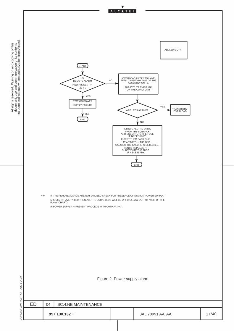
All
right
s re
serv
ed. P
assi
ng o
n an
d co
pyin
g of
this
docu
men
t, us
e an
d co
mm
unic
atio
n of
its
cont
ents
not p
erm
itted
with
out w
ritte
n au
thor
izat
ion
from
Alc
atel
.
ED
1AA
000
14 0
004
(900
7) A
4 –
ALI
CE
04.
10
17
04
957.130.132 T
SC.4:NE MAINTENANCE
/3AL 78991 AA AA
40
40
START
ISREMOTE ALARM
TAND PRESENT ?(N.B.)
NO
STATION POWER
SUPPLY FAILURE
END
OVERLOAD LIKELY TO HAVEBEEN CAUSED BY ONE OF THE
ASSEMBLY UNITS.
REMOVE ALL THE UNITS
INSERT THEM BACK ONEAT A TIME TILL THE ONE
CAUSING THE FAILURE IS DETECTED.HENCE REPLACE IT.
END
ALL LED’S OFF
N.B. IF THE REMOTE ALARMS ARE NOT UTILIZED CHECK FOR PRESENCE OF STATION POWER SUPPLY.
SHOULD IT HAVE FAILED THEN ALL THE UNIT’S LEDS WILL BE OFF (FOLLOW OUTPUT “YES” OF THEFLOW–CHART).
IF POWER SUPPLY IS PRESENT PROCEDE WITH OUTPUT “NO”.
NO
YES
YES
SUBSTITUTE THE FUSE ON THE CONGI UNIT
ARE LEDS ACTIVE?YES
TRANSITORY OVERLOAD
FROM THE SUBRACKAND SUBSTITUTE THE FUSE
IF NECESSARY.
SUBSTITUTE THE FUSE IF NECESSARY.
Figure 2. Power supply alarm
All
right
s re
serv
ed. P
assi
ng o
n an
d co
pyin
g of
this
docu
men
t, us
e an
d co
mm
unic
atio
n of
its
cont
ents
not p
erm
itted
with
out w
ritte
n au
thor
izat
ion
from
Alc
atel
.
ED
1AA
000
14 0
004
(900
7) A
4 –
ALI
CE
04.
10
18
04
957.130.132 T
SC.4:NE MAINTENANCE
/3AL 78991 AA AA
40
40
5.4 Troubleshooting by means of the Craft Terminal.
The troubleshoot proceeds checking the detailed information on the NE alarm by means of the craftterminal.
The information on the NE alarm will be mainly obtained by means of the craft terminal through the AlarmSurveillance data and the alarms/status indications presented in the various views, depending on thelevel of the structure under observation.Navigation across the various level views is done from higher to lower levels, by double clicking on theobjects (see instructions on “NE management” section).The NE hierarchy is organized in the following order: NE > rack > subrack > board > port > TP.
The troubleshoot procedure with the the Craft Terminal consists of the following steps:
a ) The alarms/status view organization for the equipment is shown in Figure 4. pg. 20. Observe theactive alarms on the Severity Alarm Synthesis, Domain Alarm Synthesis and ManagementStates Control Panel always present on the window (it resumes all the NE alarms).Table 3. on page 22 describes the meaning of these alarms/statuses and the relevant maintenanceactions.
b ) in case of alarm presence, access the Alarm Surveillance to troubleshoot. This application givesthe details of the detected alarms and helps for their localization.Para 5.4.4 on page 23 describes this view.
c ) It is possible to analyze the detailed alarm presence on the TPs of each ports of the NE, followingthe indication of para 5.4.5 on page 27.
d ) It is also possible to check alarm and status at Board view, Subrack view and Equipment vieware also supplied following the indication of para 5.4.6 on page 29 and para 5.4.8 on page 33.
e ) Eventual housekeeping alarms can be localized following the indications given in para. 5.4.9 onpage 34.
f ) These above said paragraphs describe general aspect of alarms meaning and relevant maintenanceactions that can be done with the information given in the applications.
g ) The history of past events can be obtained by means of the Event log option of the Diagnosis pulldown menu (see “NE management” section).
In case of unit replacement, follow the indications reported in Chapter. 6 on page 35.
Troubleshooting with Automatic Laser Shutdown
The Automatic Laser Shutdown (ALS) is used to protect the operator who is working with the optical fiber.When the ALS is active, it may be difficult to detect the link failed.To locate it, it is necessary to ”force on” the ALS, thus enabling the optical power transmission on theopposite direction of the failed link.WARNING: During this phase the operator has to pay attention when working with fibers and connectors.The ABNORMAL indication inform the operator of the ALS forced condition.After having completed the maintenance, enable the ALS.The ALS states are indicated in the port view, as described in para. 5.4.5 on pg. 27.
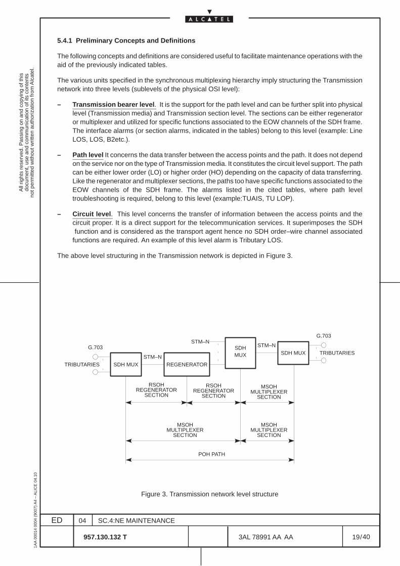
All
right
s re
serv
ed. P
assi
ng o
n an
d co
pyin
g of
this
docu
men
t, us
e an
d co
mm
unic
atio
n of
its
cont
ents
not p
erm
itted
with
out w
ritte
n au
thor
izat
ion
from
Alc
atel
.
ED
1AA
000
14 0
004
(900
7) A
4 –
ALI
CE
04.
10
19
04
957.130.132 T
SC.4:NE MAINTENANCE
/3AL 78991 AA AA
40
40
5.4.1 Preliminary Concepts and Definitions
The following concepts and definitions are considered useful to facilitate maintenance operations with theaid of the previously indicated tables.
The various units specified in the synchronous multiplexing hierarchy imply structuring the Transmissionnetwork into three levels (sublevels of the physical OSI level):
– Transmission bearer level. It is the support for the path level and can be further split into physicallevel (Transmission media) and Transmission section level. The sections can be either regeneratoror multiplexer and utilized for specific functions associated to the EOW channels of the SDH frame.The interface alarms (or section alarms, indicated in the tables) belong to this level (example: LineLOS, LOS, B2etc.).
– Path level It concerns the data transfer between the access points and the path. It does not dependon the service nor on the type of Transmission media. It constitutes the circuit level support. The pathcan be either lower order (LO) or higher order (HO) depending on the capacity of data transferring.Like the regenerator and multiplexer sections, the paths too have specific functions associated to theEOW channels of the SDH frame. The alarms listed in the cited tables, where path leveltroubleshooting is required, belong to this level (example:TUAIS, TU LOP).
– Circuit level. This level concerns the transfer of information between the access points and thecircuit proper. It is a direct support for the telecommunication services. It superimposes the SDH function and is considered as the transport agent hence no SDH order–wire channel associatedfunctions are required. An example of this level alarm is Tributary LOS.
The above level structuring in the Transmission network is depicted in Figure 3.
TRIBUTARIES SDH MUX
G.703
STM–NREGENERATOR
SDHMUX
STM–N
TRIBUTARIESSDH MUX
G.703
STM–N
RSOHREGENERATOR
SECTION
RSOHREGENERATOR
SECTION
MSOHMULTIPLEXER
SECTION
MSOHMULTIPLEXER
SECTION
POH PATH
MSOHMULTIPLEXER
SECTION
Figure 3. Transmission network level structure
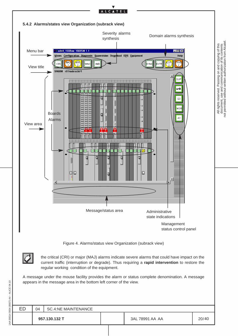
All
right
s re
serv
ed. P
assi
ng o
n an
d co
pyin
g of
this
docu
men
t, us
e an
d co
mm
unic
atio
n of
its
cont
ents
not p
erm
itted
with
out w
ritte
n au
thor
izat
ion
from
Alc
atel
.
ED
1AA
000
14 0
004
(900
7) A
4 –
ALI
CE
04.
10
20
04
957.130.132 T
SC.4:NE MAINTENANCE
/3AL 78991 AA AA
40
40
5.4.2 Alarms/states view Organization (subrack view)
Severity alarmssynthesis
Message/status area
View area
View title
Domain alarms synthesis
Management status control panel
Menu bar
Administrativestate indications
Boards
Alarms
Figure 4. Alarms/status view Organization (subrack view)
the critical (CRI) or major (MAJ) alarms indicate severe alarms that could have impact on thecurrent traffic (interruption or degrade). Thus requiring a rapid intervention to restore theregular working condition of the equipment.
A message under the mouse facility provides the alarm or status complete denomination. A messageappears in the message area in the bottom left corner of the view.

All
right
s re
serv
ed. P
assi
ng o
n an
d co
pyin
g of
this
docu
men
t, us
e an
d co
mm
unic
atio
n of
its
cont
ents
not p
erm
itted
with
out w
ritte
n au
thor
izat
ion
from
Alc
atel
.
ED
1AA
000
14 0
004
(900
7) A
4 –
ALI
CE
04.
10
21
04
957.130.132 T
SC.4:NE MAINTENANCE
/3AL 78991 AA AA
40
40
5.4.3 Alarm synthesis indication
Alarms and Statuses synthesis are given in all the screens.
The alarms CRI, MAJ, MIN, WNG, IND are part of the Severity Alarms Synthesis area, presented inTable 3. on page 22.
The alarms EXTP, EQP, TRNS are part of the Domain Alarms Synthesis area, presented inTable 4. onpage 22.
The alarms SUP, LAC, Q3, MGR, AC are part of the Management States Control Panel, presented inTable 5. on page 22.
All these indications (except for SUP, LAC, Q3, MGR,) are the summaries of particular types of alarmsdetected by the equipment, hence the specific cause of alarm is to be found as indicated in the followingparagraphs: 5.4.4, 5.4.5, 5.4.6, 5.4.7, 5.4.9.
Table 1. reports the association between the colors of the Alarms and their Severity.
For the Domain Alarms Synthesis the color corresponds to the highest severity among the set of theactive alarms for the relevant domain, according to the same rules of previous Table 1.
Table 2. reports the colors of the Management States Control Panel when not in “normal” condition.
Table 1. Alarms colors and Severity association
Alarm Color Severity
RED CRITICAL
ORANGE MAJOR
YELLOW MINOR
PALE BLUE WARNING
WHITE INDETERMINATE
GREEN NO ALARM
Table 2. Colors of the Management States when not in “normal” condition
State State Color
SUP: not supervised BROWN
LOCAL ACCESS STATE: denied CYAN
Q3: NE unreachable RED
MGR: managed by RM CYAN
AC: Abnormal Condition is active CYAN
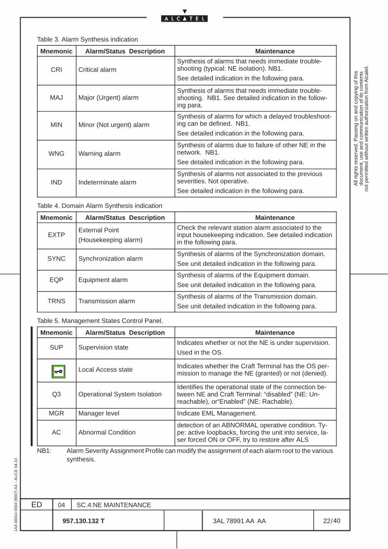
All
right
s re
serv
ed. P
assi
ng o
n an
d co
pyin
g of
this
docu
men
t, us
e an
d co
mm
unic
atio
n of
its
cont
ents
not p
erm
itted
with
out w
ritte
n au
thor
izat
ion
from
Alc
atel
.
ED
1AA
000
14 0
004
(900
7) A
4 –
ALI
CE
04.
10
22
04
957.130.132 T
SC.4:NE MAINTENANCE
/3AL 78991 AA AA
40
40
Table 3. Alarm Synthesis indication
Mnemonic Alarm/Status Description Maintenance
CRI Critical alarmSynthesis of alarms that needs immediate trouble-shooting (typical: NE isolation). NB1.
See detailed indication in the following para.
Synthesis of alarms that needs immediate trouble-MAJ Major (Urgent) alarm shooting. NB1. See detailed indication in the follow-
ing para.
MIN Minor (Not urgent) alarmSynthesis of alarms for which a delayed troubleshoot-ing can be defined. NB1.
See detailed indication in the following para.
WNG Warning alarmSynthesis of alarms due to failure of other NE in thenetwork. NB1.
See detailed indication in the following para.
IND Indeterminate alarmSynthesis of alarms not associated to the previousseverities. Not operative.
See detailed indication in the following para.
Table 4. Domain Alarm Synthesis indication
Mnemonic Alarm/Status Description Maintenance
EXTPExternal Point
(Housekeeping alarm)
Check the relevant station alarm associated to theinput housekeeping indication. See detailed indicationin the following para.
SYNC Synchronization alarmSynthesis of alarms of the Synchronization domain.
See unit detailed indication in the following para.
EQP Equipment alarmSynthesis of alarms of the Equipment domain.
See unit detailed indication in the following para.
TRNS Transmission alarmSynthesis of alarms of the Transmission domain.
See unit detailed indication in the following para.
Table 5. Management States Control Panel.
Mnemonic Alarm/Status Description Maintenance
SUP Supervision stateIndicates whether or not the NE is under supervision.
Used in the OS.
Local Access state Indicates whether the Craft Terminal has the OS per-mission to manage the NE (granted) or not (denied).
Q3 Operational System IsolationIdentifies the operational state of the connection be-tween NE and Craft Terminal: “disabled” (NE: Un-reachable), or“Enabled” (NE: Rachable).
MGR Manager level Indicate EML Management.
AC Abnormal Conditiondetection of an ABNORMAL operative condition. Ty-pe: active loopbacks, forcing the unit into service, la-ser forced ON or OFF, try to restore after ALS
NB1: Alarm Severity Assignment Profile can modify the assignment of each alarm root to the varioussynthesis.
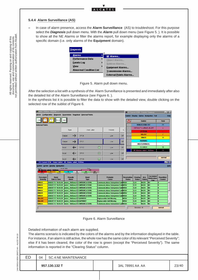
All
right
s re
serv
ed. P
assi
ng o
n an
d co
pyin
g of
this
docu
men
t, us
e an
d co
mm
unic
atio
n of
its
cont
ents
not p
erm
itted
with
out w
ritte
n au
thor
izat
ion
from
Alc
atel
.
ED
1AA
000
14 0
004
(900
7) A
4 –
ALI
CE
04.
10
23
04
957.130.132 T
SC.4:NE MAINTENANCE
/3AL 78991 AA AA
40
40
5.4.4 Alarm Surveillance (AS)
– In case of alarm presence, access the Alarm Surveillance (AS) to troubleshoot. For this purposeselect the Diagnosis pull down menu. With the Alarm pull down menu (see Figure 5. ). It is possibleto show all the NE Alarms or filter the alarms report, for example displaying only the alarms of aspecific domain (i.e. only alarms of the Equipment domain).
Figure 5. Alarm pull down menu.
After the selection a list with a synthesis of the Alarm Surveillance is presented and immediately after alsothe detailed list of the Alarm Surveillance (see Figure 6. ).In the synthesis list it is possible to filter the data to show with the detailed view, double clicking on theselected row of the sublist of Figure 6.
Figure 6. Alarm Surveillance
Detailed information of each alarm are supplied.The alarms scenario is indicated by the colors of the alarms and by the information displayed in the table.For instance, if an alarm is still active, the whole row has the same color of its relevant “Perceived Severity”;else if it has been cleared, the color of the row is green (except the “Perceived Severity”). The sameinformation is reported in the “Clearing Status” column.
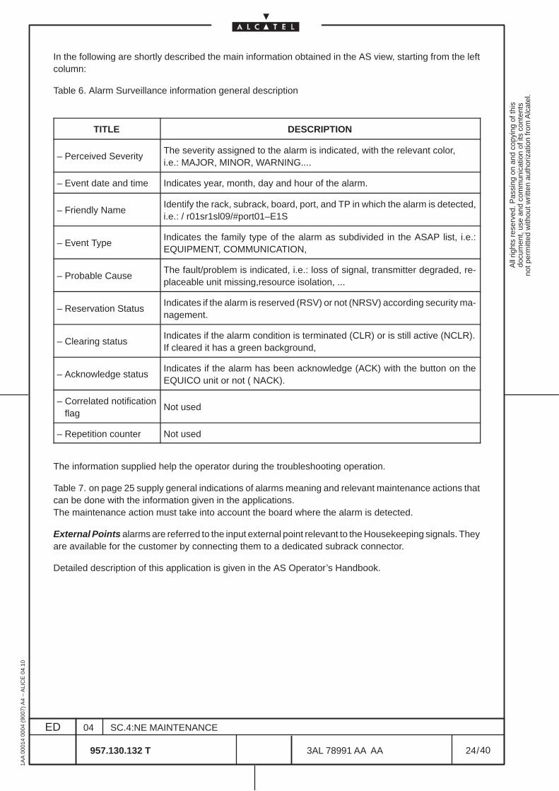
All
right
s re
serv
ed. P
assi
ng o
n an
d co
pyin
g of
this
docu
men
t, us
e an
d co
mm
unic
atio
n of
its
cont
ents
not p
erm
itted
with
out w
ritte
n au
thor
izat
ion
from
Alc
atel
.
ED
1AA
000
14 0
004
(900
7) A
4 –
ALI
CE
04.
10
24
04
957.130.132 T
SC.4:NE MAINTENANCE
/3AL 78991 AA AA
40
40
In the following are shortly described the main information obtained in the AS view, starting from the leftcolumn:
Table 6. Alarm Surveillance information general description
TITLE DESCRIPTION
– Perceived SeverityThe severity assigned to the alarm is indicated, with the relevant color,i.e.: MAJOR, MINOR, WARNING....
– Event date and time Indicates year, month, day and hour of the alarm.
– Friendly NameIdentify the rack, subrack, board, port, and TP in which the alarm is detected,i.e.: / r01sr1sl09/#port01–E1S
– Event TypeIndicates the family type of the alarm as subdivided in the ASAP list, i.e.:EQUIPMENT, COMMUNICATION,
– Probable CauseThe fault/problem is indicated, i.e.: loss of signal, transmitter degraded, re-placeable unit missing,resource isolation, ...
– Reservation StatusIndicates if the alarm is reserved (RSV) or not (NRSV) according security ma-nagement.
– Clearing statusIndicates if the alarm condition is terminated (CLR) or is still active (NCLR).If cleared it has a green background,
– Acknowledge statusIndicates if the alarm has been acknowledge (ACK) with the button on theEQUICO unit or not ( NACK).
– Correlated notification flag
Not used
– Repetition counter Not used
The information supplied help the operator during the troubleshooting operation.
Table 7. on page 25 supply general indications of alarms meaning and relevant maintenance actions thatcan be done with the information given in the applications.The maintenance action must take into account the board where the alarm is detected.
External Points alarms are referred to the input external point relevant to the Housekeeping signals. Theyare available for the customer by connecting them to a dedicated subrack connector.
Detailed description of this application is given in the AS Operator’s Handbook.
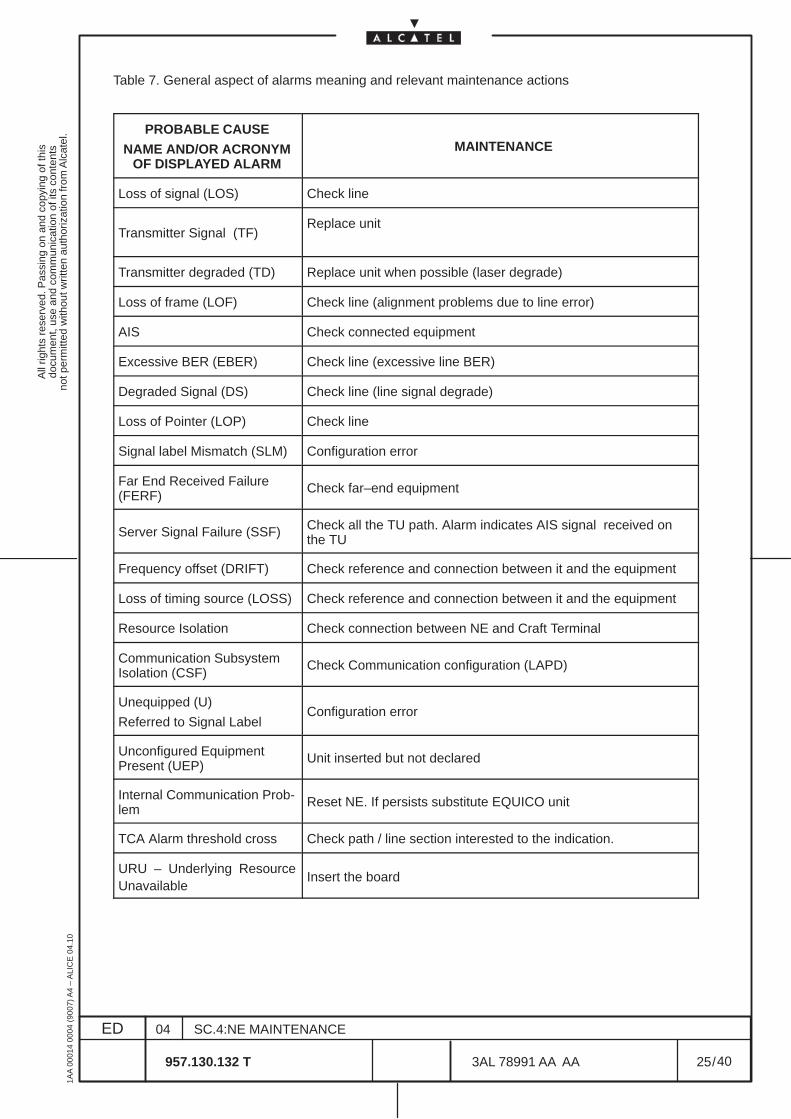
All
right
s re
serv
ed. P
assi
ng o
n an
d co
pyin
g of
this
docu
men
t, us
e an
d co
mm
unic
atio
n of
its
cont
ents
not p
erm
itted
with
out w
ritte
n au
thor
izat
ion
from
Alc
atel
.
ED
1AA
000
14 0
004
(900
7) A
4 –
ALI
CE
04.
10
25
04
957.130.132 T
SC.4:NE MAINTENANCE
/3AL 78991 AA AA
40
40
Table 7. General aspect of alarms meaning and relevant maintenance actions
PROBABLE CAUSE
NAME AND/OR ACRONYMOF DISPLAYED ALARM
MAINTENANCE
Loss of signal (LOS) Check line
Transmitter Signal (TF)Replace unit
Transmitter degraded (TD) Replace unit when possible (laser degrade)
Loss of frame (LOF) Check line (alignment problems due to line error)
AIS Check connected equipment
Excessive BER (EBER) Check line (excessive line BER)
Degraded Signal (DS) Check line (line signal degrade)
Loss of Pointer (LOP) Check line
Signal label Mismatch (SLM) Configuration error
Far End Received Failure(FERF)
Check far–end equipment
Server Signal Failure (SSF) Check all the TU path. Alarm indicates AIS signal received onthe TU
Frequency offset (DRIFT) Check reference and connection between it and the equipment
Loss of timing source (LOSS) Check reference and connection between it and the equipment
Resource Isolation Check connection between NE and Craft Terminal
Communication SubsystemIsolation (CSF)
Check Communication configuration (LAPD)
Unequipped (U)
Referred to Signal LabelConfiguration error
Unconfigured EquipmentPresent (UEP)
Unit inserted but not declared
Internal Communication Prob-lem
Reset NE. If persists substitute EQUICO unit
TCA Alarm threshold cross Check path / line section interested to the indication.
URU – Underlying ResourceUnavailable
Insert the board
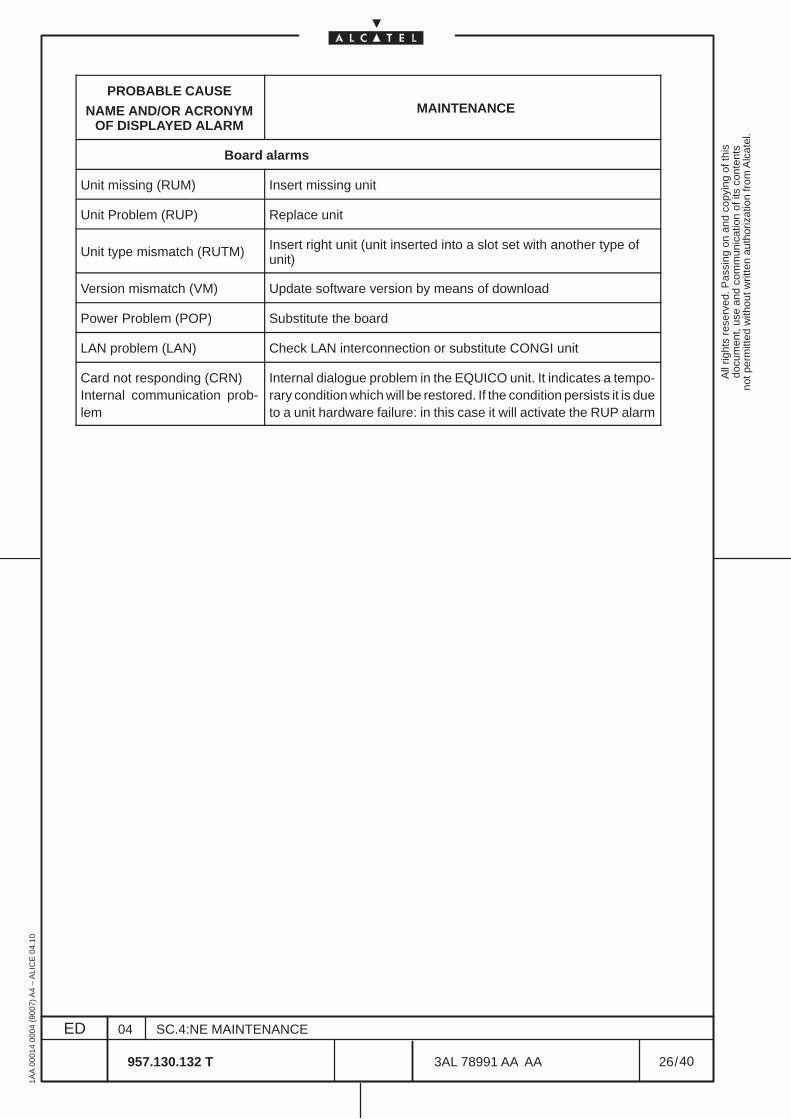
All
right
s re
serv
ed. P
assi
ng o
n an
d co
pyin
g of
this
docu
men
t, us
e an
d co
mm
unic
atio
n of
its
cont
ents
not p
erm
itted
with
out w
ritte
n au
thor
izat
ion
from
Alc
atel
.
ED
1AA
000
14 0
004
(900
7) A
4 –
ALI
CE
04.
10
26
04
957.130.132 T
SC.4:NE MAINTENANCE
/3AL 78991 AA AA
40
40
PROBABLE CAUSE
NAME AND/OR ACRONYMOF DISPLAYED ALARM
MAINTENANCE
Board alarms
Unit missing (RUM) Insert missing unit
Unit Problem (RUP) Replace unit
Unit type mismatch (RUTM) Insert right unit (unit inserted into a slot set with another type ofunit)
Version mismatch (VM) Update software version by means of download
Power Problem (POP) Substitute the board
LAN problem (LAN) Check LAN interconnection or substitute CONGI unit
Card not responding (CRN)Internal communication prob-lem
Internal dialogue problem in the EQUICO unit. It indicates a tempo-rary condition which will be restored. If the condition persists it is dueto a unit hardware failure: in this case it will activate the RUP alarm
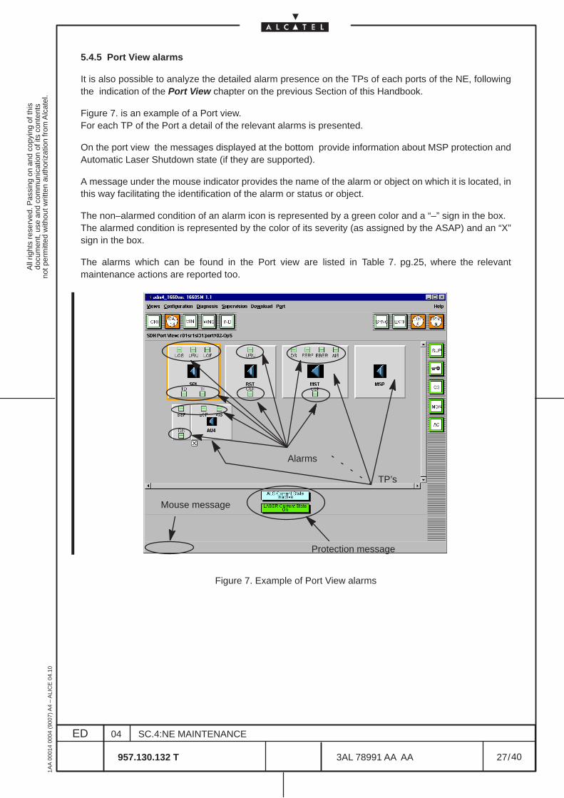
All
right
s re
serv
ed. P
assi
ng o
n an
d co
pyin
g of
this
docu
men
t, us
e an
d co
mm
unic
atio
n of
its
cont
ents
not p
erm
itted
with
out w
ritte
n au
thor
izat
ion
from
Alc
atel
.
ED
1AA
000
14 0
004
(900
7) A
4 –
ALI
CE
04.
10
27
04
957.130.132 T
SC.4:NE MAINTENANCE
/3AL 78991 AA AA
40
40
5.4.5 Port View alarms
It is also possible to analyze the detailed alarm presence on the TPs of each ports of the NE, followingthe indication of the Port View chapter on the previous Section of this Handbook.
Figure 7. is an example of a Port view.For each TP of the Port a detail of the relevant alarms is presented.
On the port view the messages displayed at the bottom provide information about MSP protection andAutomatic Laser Shutdown state (if they are supported).
A message under the mouse indicator provides the name of the alarm or object on which it is located, inthis way facilitating the identification of the alarm or status or object.
The non–alarmed condition of an alarm icon is represented by a green color and a “–” sign in the box.The alarmed condition is represented by the color of its severity (as assigned by the ASAP) and an “X”sign in the box.
The alarms which can be found in the Port view are listed in Table 7. pg.25, where the relevantmaintenance actions are reported too.
Alarms
Protection message
Mouse message
TP’s
Figure 7. Example of Port View alarms
All
right
s re
serv
ed. P
assi
ng o
n an
d co
pyin
g of
this
docu
men
t, us
e an
d co
mm
unic
atio
n of
its
cont
ents
not p
erm
itted
with
out w
ritte
n au
thor
izat
ion
from
Alc
atel
.
ED
1AA
000
14 0
004
(900
7) A
4 –
ALI
CE
04.
10
28
04
957.130.132 T
SC.4:NE MAINTENANCE
/3AL 78991 AA AA
40
40
The information regarding ALS states and Laser state useful for operators safety purpose arereported in the following:
ALS states:
Inactive = No ALS has been activated (Off) or the laser has been Forced ON/OFF.
In test = The laser restart has been automatically activated .
Active = The ALS has been activated (On).
Undefined = The ALS is not present (not created).
Laser state:
On = all OK or ALS not present (not created).
Off = Laser off (when ALS is created).
Forced on = ALS forced on by operator command.
Forced off = ALS forced off by operator command.
All
right
s re
serv
ed. P
assi
ng o
n an
d co
pyin
g of
this
docu
men
t, us
e an
d co
mm
unic
atio
n of
its
cont
ents
not p
erm
itted
with
out w
ritte
n au
thor
izat
ion
from
Alc
atel
.
ED
1AA
000
14 0
004
(900
7) A
4 –
ALI
CE
04.
10
29
04
957.130.132 T
SC.4:NE MAINTENANCE
/3AL 78991 AA AA
40
40
5.4.6 Board view alarms and states
The alarm and status indications at Board level can be obtained, following the indication of the Board Viewchapter on the previous Section of this Handbook.
Figure 8. shows an example of Board view.
The alarm and status indications depend on the unit type; for example SDH units is organized on two levelsof presentation (in the first is selected one of the available ports) and each view contains dedicatedindications.An alarm box is displayed on each port, to indicate whether the port is alarmed.
An indication in the ”message/status area” provides information about the board Administrative State:“in–service” or “out–of–service”.
The alarms of the board are reported at the bottom of the ”message/status area”, by means of variousboxes containing relevant acronyms.The non–alarmed condition of an alarm icon is represented by a green color.The alarmed condition is represented by the color of its severity (as assigned by the ASAP).
A message under the mouse indicator provides the name of the alarm or object on which it is located, inthis way facilitating the identification of the alarm or status or object.
In the view is present the Administrative State information: “in service” or “out of service”.
The alarms which can be found in the Board view are listed in Table 7. page 25, where the relevantmaintenance actions are reported too.
In the view can also be present EPS indications.
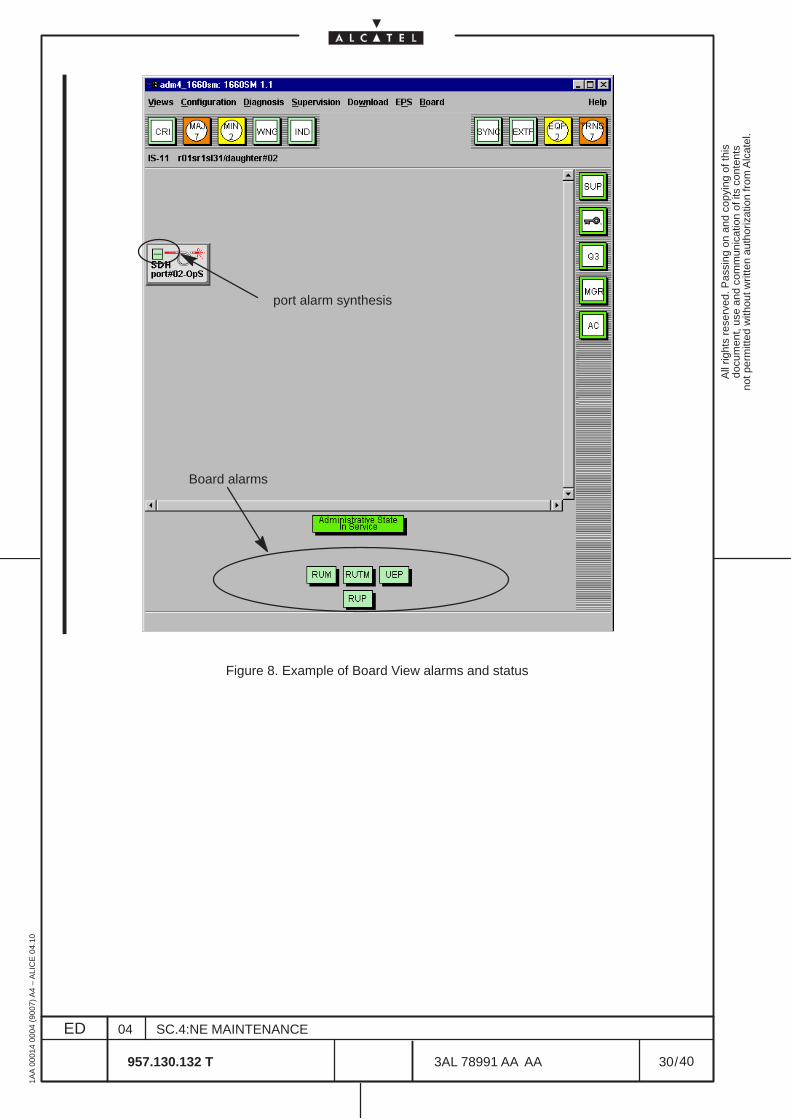
All
right
s re
serv
ed. P
assi
ng o
n an
d co
pyin
g of
this
docu
men
t, us
e an
d co
mm
unic
atio
n of
its
cont
ents
not p
erm
itted
with
out w
ritte
n au
thor
izat
ion
from
Alc
atel
.
ED
1AA
000
14 0
004
(900
7) A
4 –
ALI
CE
04.
10
30
04
957.130.132 T
SC.4:NE MAINTENANCE
/3AL 78991 AA AA
40
40
port alarm synthesis
Board alarms
Figure 8. Example of Board View alarms and status
All
right
s re
serv
ed. P
assi
ng o
n an
d co
pyin
g of
this
docu
men
t, us
e an
d co
mm
unic
atio
n of
its
cont
ents
not p
erm
itted
with
out w
ritte
n au
thor
izat
ion
from
Alc
atel
.
ED
1AA
000
14 0
004
(900
7) A
4 –
ALI
CE
04.
10
31
04
957.130.132 T
SC.4:NE MAINTENANCE
/3AL 78991 AA AA
40
40
5.4.7 Subrack view alarms
The alarms and status indications at subrack level can be obtained, following the indications given on theprevious Section of this Handbook (”NE management”).
Figure 9. shows an example of subrack view.
An alarm box is displayed on each board, to indicate whether the board is alarmed. This board alarmsummarization is activated when one of the board alarms (those reported at the bottom of the Board view)is active.
A “lock” symbol on a board indicates that it is “in–service”. Else, the lack of this symbol indicates its“out–of–service” state . (Administrative State information).
A message under the mouse indicator provides the name of the alarm or object on which it is located, inthis way facilitating the identification of the alarm or status or object.
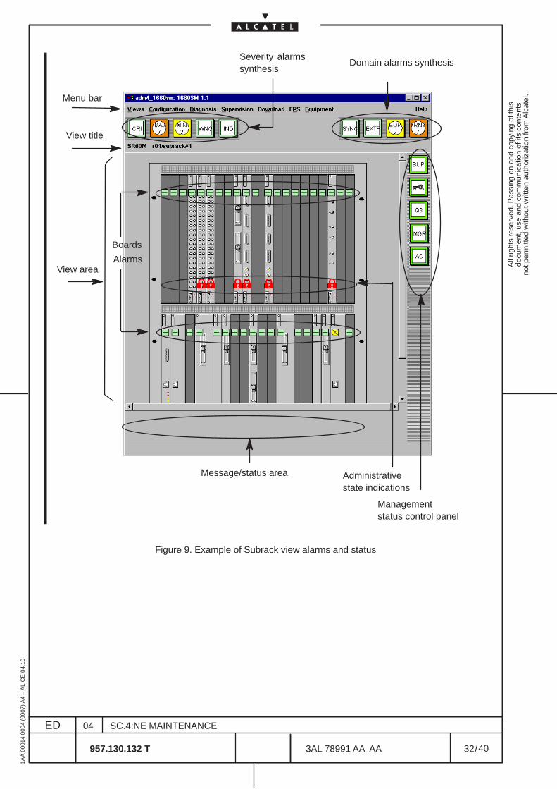
All
right
s re
serv
ed. P
assi
ng o
n an
d co
pyin
g of
this
docu
men
t, us
e an
d co
mm
unic
atio
n of
its
cont
ents
not p
erm
itted
with
out w
ritte
n au
thor
izat
ion
from
Alc
atel
.
ED
1AA
000
14 0
004
(900
7) A
4 –
ALI
CE
04.
10
32
04
957.130.132 T
SC.4:NE MAINTENANCE
/3AL 78991 AA AA
40
40
Severity alarmssynthesis
Message/status area
View area
View title
Domain alarms synthesis
Management status control panel
Menu bar
Administrativestate indications
Boards
Alarms
Figure 9. Example of Subrack view alarms and status
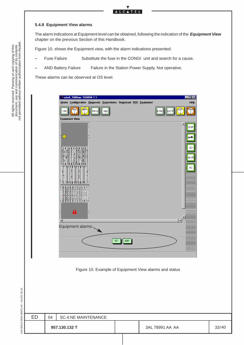
All
right
s re
serv
ed. P
assi
ng o
n an
d co
pyin
g of
this
docu
men
t, us
e an
d co
mm
unic
atio
n of
its
cont
ents
not p
erm
itted
with
out w
ritte
n au
thor
izat
ion
from
Alc
atel
.
ED
1AA
000
14 0
004
(900
7) A
4 –
ALI
CE
04.
10
33
04
957.130.132 T
SC.4:NE MAINTENANCE
/3AL 78991 AA AA
40
40
5.4.8 Equipment View alarms
The alarm indications at Equipment level can be obtained, following the indication of the Equipment Viewchapter on the previous Section of this Handbook.
Figure 10. shows the Equipment view, with the alarm indications presented:
– Fuse Failure Substitute the fuse in the CONGI unit and search for a cause.
– AND Battery Failure Failure in the Station Power Supply. Not operative.
These alarms can be observed at OS level.
Equipment alarms
Figure 10. Example of Equipment View alarms and status
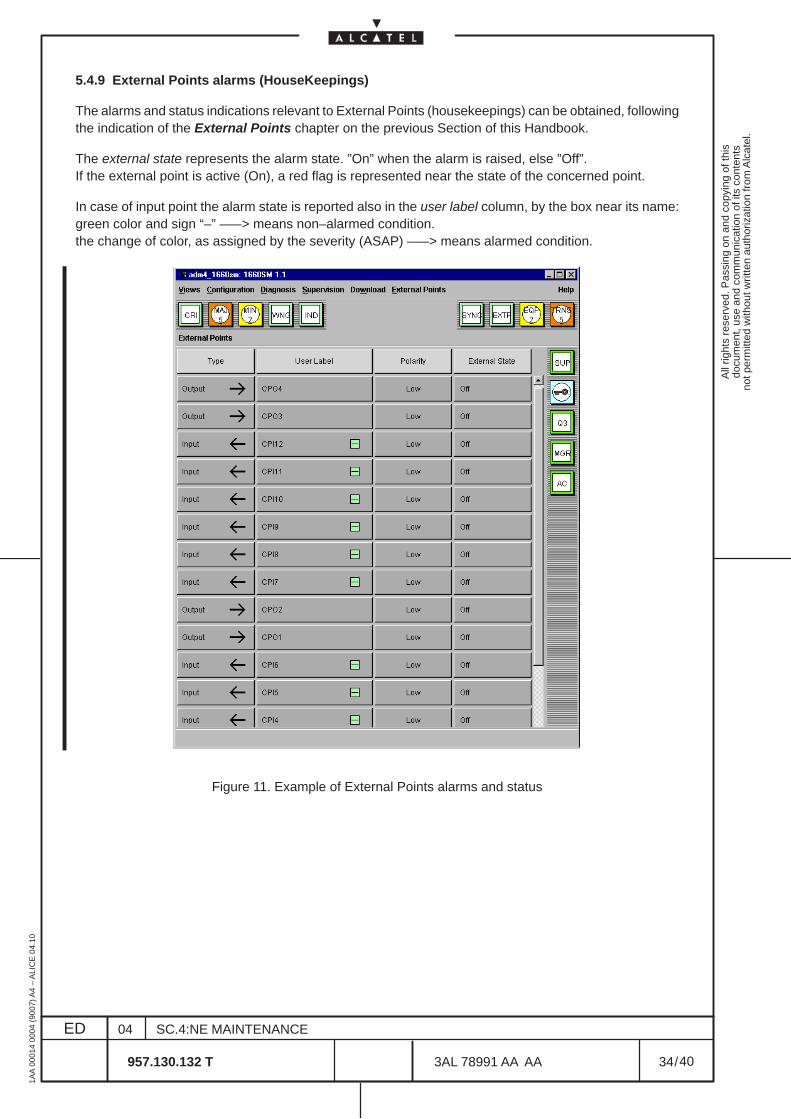
All
right
s re
serv
ed. P
assi
ng o
n an
d co
pyin
g of
this
docu
men
t, us
e an
d co
mm
unic
atio
n of
its
cont
ents
not p
erm
itted
with
out w
ritte
n au
thor
izat
ion
from
Alc
atel
.
ED
1AA
000
14 0
004
(900
7) A
4 –
ALI
CE
04.
10
34
04
957.130.132 T
SC.4:NE MAINTENANCE
/3AL 78991 AA AA
40
40
5.4.9 External Points alarms (HouseKeepings)
The alarms and status indications relevant to External Points (housekeepings) can be obtained, followingthe indication of the External Points chapter on the previous Section of this Handbook.
The external state represents the alarm state. ”On” when the alarm is raised, else ”Off”.If the external point is active (On), a red flag is represented near the state of the concerned point.
In case of input point the alarm state is reported also in the user label column, by the box near its name:green color and sign “–” –––> means non–alarmed condition.the change of color, as assigned by the severity (ASAP) –––> means alarmed condition.
Figure 11. Example of External Points alarms and status

All
right
s re
serv
ed. P
assi
ng o
n an
d co
pyin
g of
this
docu
men
t, us
e an
d co
mm
unic
atio
n of
its
cont
ents
not p
erm
itted
with
out w
ritte
n au
thor
izat
ion
from
Alc
atel
.
ED
1AA
000
14 0
004
(900
7) A
4 –
ALI
CE
04.
10
35
04
957.130.132 T
SC.4:NE MAINTENANCE
/3AL 78991 AA AA
40
40
6 UNIT REPLACEMENT WITH A SPARE
No particular indication is given as to spare handling which is left to the Maintenance Administration.
The replacement procedures are executed as follows:
– Hardware set the spare unit exactly as the unit to replace. Settings are specified in the MSdocuments. Here a layout figure indicates the exact location of all the setting arrangements and atable relate the operations to achieve with the settings.The cited documents are enclosed in the Technical Handbook.
– Simply replace those units not provided with any software settings
– With regard to the EQUICO unit refer to the following paragraph.
– When upgrading an equipment with “New Hardware” (for example MATRIXN unit) that substitute theold units (for example MATRIX unit), follow the indication given in paragraph on page .
6.1 EQUICO unit replacement
Various procedures are utilized to replace a EQUICO faulty unit. They depend on the type of sparesavailable:
• Spare without software installed. This is the normal condition.
• Spares with installed software, belonging to the same type of equipment and with SW releaseidentical to the unit to replace
• Spares with installed software, belonging to the same type of equipment but with SW releasediffering from the one of the unit to replace, or belonging to other types of equipment orunknown.
– CONGI unit version (read NOTE in Figure 12. on page 36)
– MIB store in the Craft Terminal or O.S.
The flow–chart of Figure 12. on page 36 illustrates the procedures to follow for the EQUICO substitution.
The procedure aim is to replace the faulty unit without causing configuration changes and/or unwantedfaults; when not possible this is indicated in the flow chart.
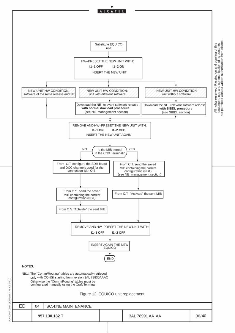
All
right
s re
serv
ed. P
assi
ng o
n an
d co
pyin
g of
this
docu
men
t, us
e an
d co
mm
unic
atio
n of
its
cont
ents
not p
erm
itted
with
out w
ritte
n au
thor
izat
ion
from
Alc
atel
.
ED
1AA
000
14 0
004
(900
7) A
4 –
ALI
CE
04.
10
36
04
957.130.132 T
SC.4:NE MAINTENANCE
/3AL 78991 AA AA
40
40
ÉÉÉÉÉÉÉÉÉÉÉÉÉÉÉÉÉÉÉÉÉÉÉÉÉÉÉÉÉÉÉÉÉ
ÉÉÉÉÉÉÉÉÉÉÉÉÉÉÉÉÉÉÉÉÉÉÉÉÉÉÉÉÉÉ
ÉÉÉÉÉÉÉÉÉÉÉÉÉÉÉÉÉÉÉÉÉÉÉÉÉÉÉÉÉÉ
unit without software
Download the NE relevant software releasewith SIBDL procedure
(see SIBDL section)
software of thesame release and NE
END
unit with different software
Download the NE relevant software release
(see NE management section)with normal dowload procedure.
”Activate” the sent MIB
I1–1 OFF I1–2 OFF
INSERT AGAIN THE NEWEQUICO
NOTES:
NB2: The ”Comm/Routing” tables are automatically retrievedonly with CONGI starting from version 3AL 78830AAACOtherwise the ”Comm/Routing” tables must be configurated manually using the Craft Terminal
Is the MIB storedin the Craft Terminal?
YESNO
MIB containing the correctconfiguration (NB1)
From O.S. send the saved
MIB containing the correctconfiguration (NB1)
From C.T. send the saved
(see NE management section)
”Activate” the sent MIBFrom O.S.
From C.T.
NEW UNIT HW CONDITION: NEW UNIT HW CONDITION: NEW UNIT HW CONDITION:
HW–PRESET THE NEW
I1–1 ON I1–2 OFFUNIT WITH:
HW–PRESET THE NEW UNIT WITH:
I1–1 OFF I1–2 ON
REMOVE AND
Substitute EQUICOunit
NB1
and DCC channels used for the connection with O.S.
From C.T. configure the SDH board
INSERT THE NEW UNIT
INSERT THE NEW UNIT AGAIN
HW–PRESET THE NEW UNIT WITH:REMOVE AND
Figure 12. EQUICO unit replacement

All
right
s re
serv
ed. P
assi
ng o
n an
d co
pyin
g of
this
docu
men
t, us
e an
d co
mm
unic
atio
n of
its
cont
ents
not p
erm
itted
with
out w
ritte
n au
thor
izat
ion
from
Alc
atel
.
ED
1AA
000
14 0
004
(900
7) A
4 –
ALI
CE
04.
10
37
04
957.130.132 T
SC.4:NE MAINTENANCE
/3AL 78991 AA AA
40
40
7 UPGRADING WITH NEW HARDWARE
In the next paragraphs is indicated the procedure to follow when upgrading an equipment with “NewHardware” .
The new Hardware is identify by the “N” letter at the end of the acronym unit (for example MATRIXN isthe new version, MATRIX without “N” is the old version).
This procedure permits, if the equipment is EPS protected and inserted in a protected network (linear orring protection), to maintain the system “in service”
All
right
s re
serv
ed. P
assi
ng o
n an
d co
pyin
g of
this
docu
men
t, us
e an
d co
mm
unic
atio
n of
its
cont
ents
not p
erm
itted
with
out w
ritte
n au
thor
izat
ion
from
Alc
atel
.
ED
1AA
000
14 0
004
(900
7) A
4 –
ALI
CE
04.
10
38
04
957.130.132 T
SC.4:NE MAINTENANCE
/3AL 78991 AA AA
40
40
7.1 MATRIX substitution with MATRIXN
According to the MATRIX EPS protection scheme different procedure are available:
[1] Upgrading with a new MATRIXN EPS not protected
Substituting the old MATRIX all the traffic is lost!
• Remove the old MATRIX in slot 23 from the subrack
• Insert the new MATRIX into the subrack slot 23; on Craft Terminal a RUTM (unit type mismatch)alarm will be present.
• On Craft Terminal in the Subrack level view select the slot where the new unit has been inserted
• Select the Modify option from the Equipment menu and select the acronym of the new unit( MATRIXN) from the list, then click on ok.
• Verify that the RUTM alarm disappear
[2] Upgrading with a new MATRIXN EPS protected
• Remove first the Stand–by MATRIX from the subrack
• Insert the new MATRIXN into the subrack slot previously occupied by the old MATRIX; a RUTM(unit type mismatch) alarm will be present.
• On Craft Terminal in the Subrack level view select the slot where the new unit has been inserted
• Select the Modify option from the Equipment menu and select the MATRIXN acronym fromthe list then click on ok.
• Verify that the RUTM alarm disappear
• Force the EPS Switching to the Stand–by MATRIXN by selecting the Switch option from theEPS menu. For details see the paragraph “Switching EPS” in the “NE MANAGEMENT” sectionof this Handbook.
• After having verify that the MATRIXN (previously in Stand–by) is now working, remove theMATRIX unit (previously working) from the subrack.
• Insert the new MATRIXN into the subrack slot previously occupied by the old MATRIX; a RUTM(unit type mismatch) alarm will be present.
• On Craft Terminal in the Subrack level view select the slot where the new unit has been inserted
• Select the Modify option from the Equipment menu and select the MATRIXN acronym fromthe list then click on ok.
• Verify that the RUTM alarm disappear
• The decision to force again the EPS MATRIXN switching to restore the original workingcondition is left to the operator.
All
right
s re
serv
ed. P
assi
ng o
n an
d co
pyin
g of
this
docu
men
t, us
e an
d co
mm
unic
atio
n of
its
cont
ents
not p
erm
itted
with
out w
ritte
n au
thor
izat
ion
from
Alc
atel
.
ED
1AA
000
14 0
004
(900
7) A
4 –
ALI
CE
04.
10
39
04
957.130.132 T
SC.4:NE MAINTENANCE
/3AL 78991 AA AA
40
40
7.2 P4S1, S–41, L–41, L–42, S–161, L–161, L–162 substitution with P4S1N,S–41N, L–41N, L–42N , S–161N, L–161N, L–162N
During the substitution the traffic carried by the units will be lost if not SNCP or MSP protected
In the following an example will be given substituting a P4S1 with a P4S1N; the same procedure canbe applied to substitute the S–41, L–41, L–42, S–161, L–161, L–162 units respectively with S–41N,L–41N, L–42N , S–161N, L–161N, L–162N units.
• Remove the old unit( example P4S1 ) from the subrack
• Insert the new unit (example P4S1N) into the subrack slot previously occupied by the old unit;on Craft Terminal a RUTM (unit type mismatch) alarm will be present.
• On Craft Terminal in the Subrack level view select the slot where the new unit has been inserted
• Select the Modify option from the Equipment menu and select the acronym of the new unit( in our example P4S1N) from the list, then click on ok.
• Verify that the RUTM alarm disappear

All
right
s re
serv
ed. P
assi
ng o
n an
d co
pyin
g of
this
docu
men
t, us
e an
d co
mm
unic
atio
n of
its
cont
ents
not p
erm
itted
with
out w
ritte
n au
thor
izat
ion
from
Alc
atel
.
ED
1AA
000
14 0
004
(900
7) A
4 –
ALI
CE
04.
10
40
04
957.130.132 T
SC.4:NE MAINTENANCE
/3AL 78991 AA AA
40
40
END OF DOCUMENT
All
right
s re
serv
ed. P
assi
ng o
n an
d co
pyin
g of
this
docu
men
t, us
e an
d co
mm
unic
atio
n of
its
cont
ents
not p
erm
itted
with
out w
ritte
n au
thor
izat
ion
from
Alc
atel
.
ED
1AA
000
14 0
004
(900
7) A
4 –
ALI
CE
04.
10
1
03
957.130.132 T
SC.5: SIBDL
/3AL 78991 AA AA
12
12
1660SM REL.1.1 C.T. OPERATOR’S HANDBOOK
TABLE OF CONTENTS
LIST OF FIGURES AND TABLES 2. . . . . . . . . . . . . . . . . . . . . . . . . . . . . . . . . . . . . . . . . . . . . . . . . . . . . . .
1 INTRODUCTION 3. . . . . . . . . . . . . . . . . . . . . . . . . . . . . . . . . . . . . . . . . . . . . . . . . . . . . . . . . . . . . . . . . . . 1.1 Scope 3. . . . . . . . . . . . . . . . . . . . . . . . . . . . . . . . . . . . . . . . . . . . . . . . . . . . . . . . . . . . . . . . . . . . . . . . .
1.1.1 Document scope 3. . . . . . . . . . . . . . . . . . . . . . . . . . . . . . . . . . . . . . . . . . . . . . . . . . . . . . . . . . . . 1.1.2 Target audience 3. . . . . . . . . . . . . . . . . . . . . . . . . . . . . . . . . . . . . . . . . . . . . . . . . . . . . . . . . . . . .
1.2 Terminology 3. . . . . . . . . . . . . . . . . . . . . . . . . . . . . . . . . . . . . . . . . . . . . . . . . . . . . . . . . . . . . . . . . . . 1.2.1 Acronyms and abbreviations 3. . . . . . . . . . . . . . . . . . . . . . . . . . . . . . . . . . . . . . . . . . . . . . . . . . 1.2.2 Glossary of terms 3. . . . . . . . . . . . . . . . . . . . . . . . . . . . . . . . . . . . . . . . . . . . . . . . . . . . . . . . . . .
2 DOWNLOAD WITH SIBDL 5. . . . . . . . . . . . . . . . . . . . . . . . . . . . . . . . . . . . . . . . . . . . . . . . . . . . . . . . . . . 2.1 Purpose of the procedure 5. . . . . . . . . . . . . . . . . . . . . . . . . . . . . . . . . . . . . . . . . . . . . . . . . . . . . . 2.1.1 SIBDL download procedure 5. . . . . . . . . . . . . . . . . . . . . . . . . . . . . . . . . . . . . . . . . . . . . . . . . .
3 CONFIGURATION FOR SIBDL 11. . . . . . . . . . . . . . . . . . . . . . . . . . . . . . . . . . . . . . . . . . . . . . . . . . . . . . . 3.1 Purpose of the procedure 11. . . . . . . . . . . . . . . . . . . . . . . . . . . . . . . . . . . . . . . . . . . . . . . . . . . . . . 3.1.1 Remote Access Service configuration 11. . . . . . . . . . . . . . . . . . . . . . . . . . . . . . . . . . . . . . . . . . 3.1.2 Serial Cable Modem configuration 11. . . . . . . . . . . . . . . . . . . . . . . . . . . . . . . . . . . . . . . . . . . . .
ED DATE CHANGE NOTE APPRAISAL AUTHORITY ORIGINATOR
01 000307 S.MAGGIO ITAVE P.GHELFI ITAVE
02A 000906 validated S.MAGGIO ITAVE P.GHELFI ITAVE
00112403 S.MAGGIO ITAVE P.GHELFI ITAVE
1660SM REL.1.1Version B1C.T. OPERATOR’S HANDBOOK
E.CORRADINI
E.CORRADINI
C. FAVERO

All
right
s re
serv
ed. P
assi
ng o
n an
d co
pyin
g of
this
docu
men
t, us
e an
d co
mm
unic
atio
n of
its
cont
ents
not p
erm
itted
with
out w
ritte
n au
thor
izat
ion
from
Alc
atel
.
ED
1AA
000
14 0
004
(900
7) A
4 –
ALI
CE
04.
10
2
03
957.130.132 T
SC.5: SIBDL
/3AL 78991 AA AA
12
12
LIST OF FIGURES AND TABLES
Figure 1. SIBDL download procedure – step 1 6. . . . . . . . . . . . . . . . . . . . . . . . . . . . . . . . . . . . . . . . . . . . Figure 2. SIBDL download procedure – step 2 6. . . . . . . . . . . . . . . . . . . . . . . . . . . . . . . . . . . . . . . . . . . . Figure 3. SIBDL download procedure – step 3 7. . . . . . . . . . . . . . . . . . . . . . . . . . . . . . . . . . . . . . . . . . . . Figure 4. SIBDL download procedure – step 4 7. . . . . . . . . . . . . . . . . . . . . . . . . . . . . . . . . . . . . . . . . . . . Figure 5. SIBDL download procedure – step 5 8. . . . . . . . . . . . . . . . . . . . . . . . . . . . . . . . . . . . . . . . . . . . Figure 6. SIBDL download procedure – step 6 8. . . . . . . . . . . . . . . . . . . . . . . . . . . . . . . . . . . . . . . . . . . . Figure 7. SIBDL download procedure – step 7 9. . . . . . . . . . . . . . . . . . . . . . . . . . . . . . . . . . . . . . . . . . . .
All
right
s re
serv
ed. P
assi
ng o
n an
d co
pyin
g of
this
docu
men
t, us
e an
d co
mm
unic
atio
n of
its
cont
ents
not p
erm
itted
with
out w
ritte
n au
thor
izat
ion
from
Alc
atel
.
ED
1AA
000
14 0
004
(900
7) A
4 –
ALI
CE
04.
10
3
03
957.130.132 T
SC.5: SIBDL
/3AL 78991 AA AA
12
12
1 INTRODUCTION
1.1 Scope
1.1.1 Document scope
The SIBDL Manual describes the SIBDL application, used to download the NE software via Q or Finterface.
The SIBDL (Standard Image Binary DownLoad) procedure contains the following operative descriptions:
– Download with SIBDL. The complete procedure is indicated. See Chapter 2 on page 5
– Configuration for SIBDL. Configurations to be performed for SIBDL operation are described. SeeChapter 3 on page 11.
1.1.2 Target audience
The SIBDL Manual is intended for all users.
The documents that should be read before starting this document are:
– 1320CT Rel. 1.1 Basic Operator’s Handbook
1.2 Terminology
1.2.1 Acronyms and abbreviations
Refer to the Section Introduction manual.
1.2.2 Glossary of terms
Refer to the Section Introduction manual.

All
right
s re
serv
ed. P
assi
ng o
n an
d co
pyin
g of
this
docu
men
t, us
e an
d co
mm
unic
atio
n of
its
cont
ents
not p
erm
itted
with
out w
ritte
n au
thor
izat
ion
from
Alc
atel
.
ED
1AA
000
14 0
004
(900
7) A
4 –
ALI
CE
04.
10
4
03
957.130.132 T
SC.5: SIBDL
/3AL 78991 AA AA
12
12
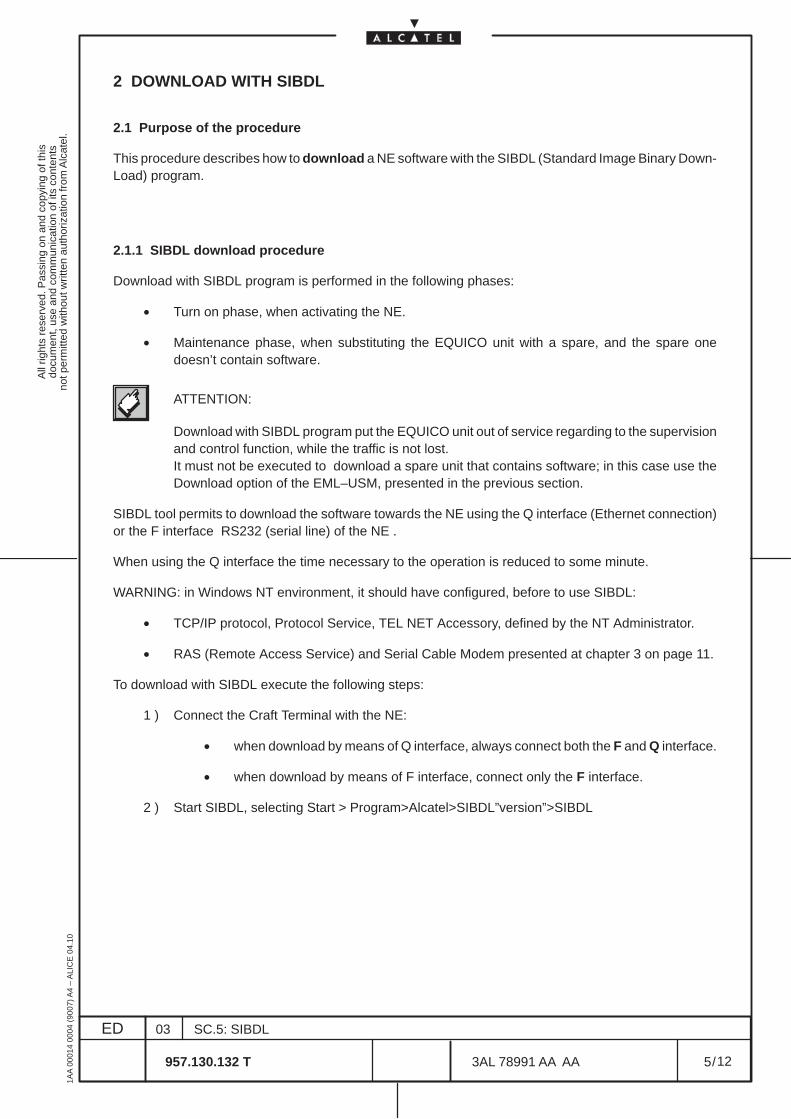
All
right
s re
serv
ed. P
assi
ng o
n an
d co
pyin
g of
this
docu
men
t, us
e an
d co
mm
unic
atio
n of
its
cont
ents
not p
erm
itted
with
out w
ritte
n au
thor
izat
ion
from
Alc
atel
.
ED
1AA
000
14 0
004
(900
7) A
4 –
ALI
CE
04.
10
5
03
957.130.132 T
SC.5: SIBDL
/3AL 78991 AA AA
12
12
2 DOWNLOAD WITH SIBDL
2.1 Purpose of the procedure
This procedure describes how to download a NE software with the SIBDL (Standard Image Binary Down-Load) program.
2.1.1 SIBDL download procedure
Download with SIBDL program is performed in the following phases:
• Turn on phase, when activating the NE.
• Maintenance phase, when substituting the EQUICO unit with a spare, and the spare onedoesn’t contain software.
ATTENTION:
Download with SIBDL program put the EQUICO unit out of service regarding to the supervisionand control function, while the traffic is not lost.It must not be executed to download a spare unit that contains software; in this case use theDownload option of the EML–USM, presented in the previous section.
SIBDL tool permits to download the software towards the NE using the Q interface (Ethernet connection)or the F interface RS232 (serial line) of the NE .
When using the Q interface the time necessary to the operation is reduced to some minute.
WARNING: in Windows NT environment, it should have configured, before to use SIBDL:
• TCP/IP protocol, Protocol Service, TEL NET Accessory, defined by the NT Administrator.
• RAS (Remote Access Service) and Serial Cable Modem presented at chapter 3 on page 11.
To download with SIBDL execute the following steps:
1 ) Connect the Craft Terminal with the NE:
• when download by means of Q interface, always connect both the F and Q interface.
• when download by means of F interface, connect only the F interface.
2 ) Start SIBDL, selecting Start > Program>Alcatel>SIBDL”version”>SIBDL
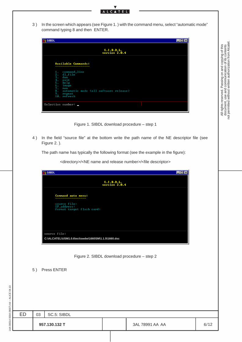
All
right
s re
serv
ed. P
assi
ng o
n an
d co
pyin
g of
this
docu
men
t, us
e an
d co
mm
unic
atio
n of
its
cont
ents
not p
erm
itted
with
out w
ritte
n au
thor
izat
ion
from
Alc
atel
.
ED
1AA
000
14 0
004
(900
7) A
4 –
ALI
CE
04.
10
6
03
957.130.132 T
SC.5: SIBDL
/3AL 78991 AA AA
12
12
3 ) In the screen which appears (see Figure 1. ) with the command menu, select “automatic mode”command typing 8 and then ENTER.
Figure 1. SIBDL download procedure – step 1
4 ) In the field “source file” at the bottom write the path name of the NE descriptor file (seeFigure 2. ).
The path name has typically the following format (see the example in the figure):
<directory>/<NE name and release number>/<file descriptor>
C:\ALCATEL\USM1.0.6\ect\swdw\1660SM\1.1.5\1660.dsc
Figure 2. SIBDL download procedure – step 2
5 ) Press ENTER
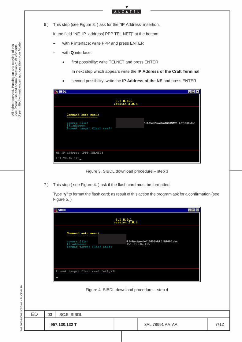
All
right
s re
serv
ed. P
assi
ng o
n an
d co
pyin
g of
this
docu
men
t, us
e an
d co
mm
unic
atio
n of
its
cont
ents
not p
erm
itted
with
out w
ritte
n au
thor
izat
ion
from
Alc
atel
.
ED
1AA
000
14 0
004
(900
7) A
4 –
ALI
CE
04.
10
7
03
957.130.132 T
SC.5: SIBDL
/3AL 78991 AA AA
12
12
6 ) This step (see Figure 3. ) ask for the “IP Address” insertion.
In the field “NE_IP_address[ PPP TEL NET]” at the bottom:
– with F interface: write PPP and press ENTER
– with Q interface:
• first possibility: write TELNET and press ENTER
In next step which appears write the IP Address of the Craft Terminal
• second possibility: write the IP Address of the NE and press ENTER
C:\ALCATEL\USM1.0.6\ect\swdw\1660SM\1.1.5\1660.dsc
Figure 3. SIBDL download procedure – step 3
7 ) This step ( see Figure 4. ) ask if the flash card must be formatted.
Type “y” to format the flash card; as result of this action the program ask for a confirmation (seeFigure 5. )
C:\ALCATEL\USM1.0.6\ect\swdw\1660SM\1.1.5\1660.dsc
Figure 4. SIBDL download procedure – step 4
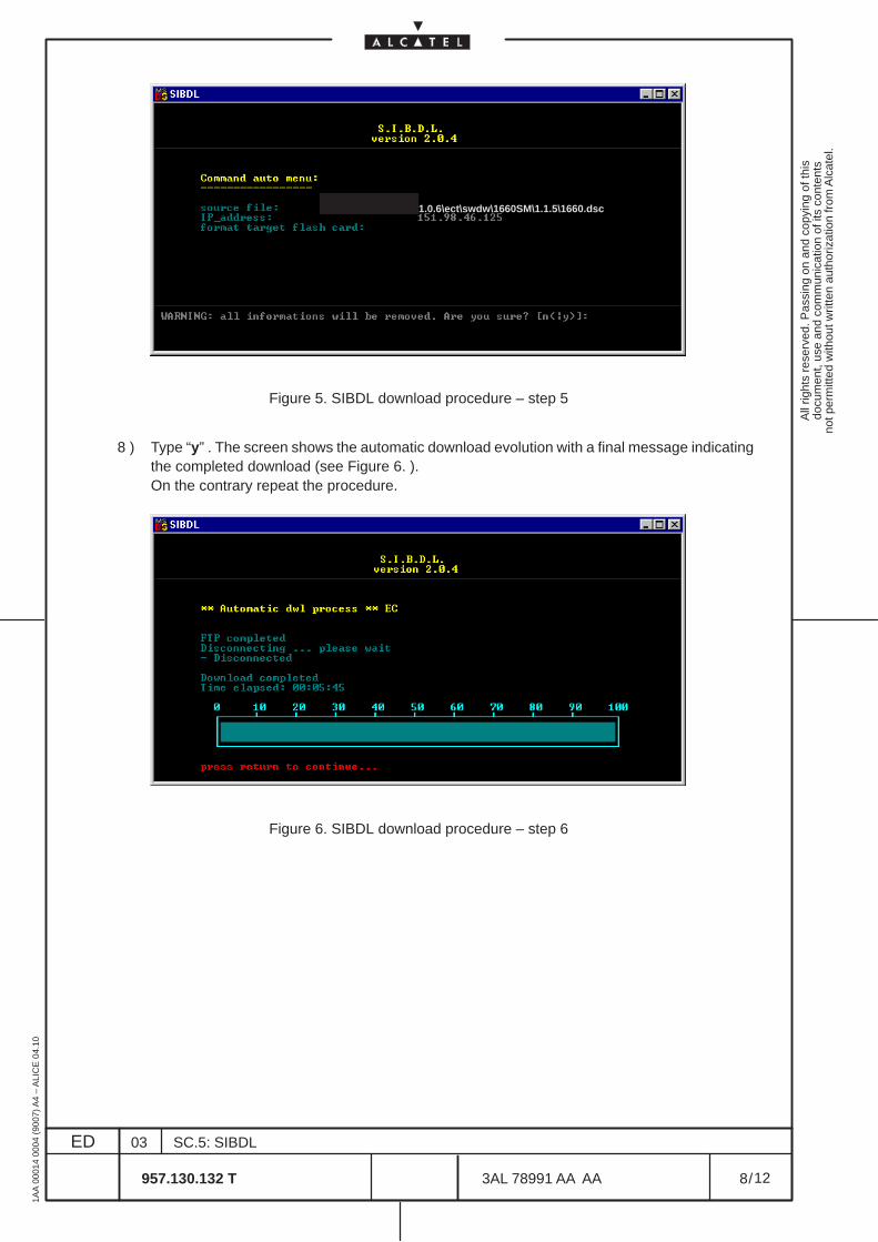
All
right
s re
serv
ed. P
assi
ng o
n an
d co
pyin
g of
this
docu
men
t, us
e an
d co
mm
unic
atio
n of
its
cont
ents
not p
erm
itted
with
out w
ritte
n au
thor
izat
ion
from
Alc
atel
.
ED
1AA
000
14 0
004
(900
7) A
4 –
ALI
CE
04.
10
8
03
957.130.132 T
SC.5: SIBDL
/3AL 78991 AA AA
12
12
C:\ALCATEL\USM1.0.6\ect\swdw\1660SM\1.1.5\1660.dsc
Figure 5. SIBDL download procedure – step 5
8 ) Type “y” . The screen shows the automatic download evolution with a final message indicatingthe completed download (see Figure 6. ).On the contrary repeat the procedure.
Figure 6. SIBDL download procedure – step 6
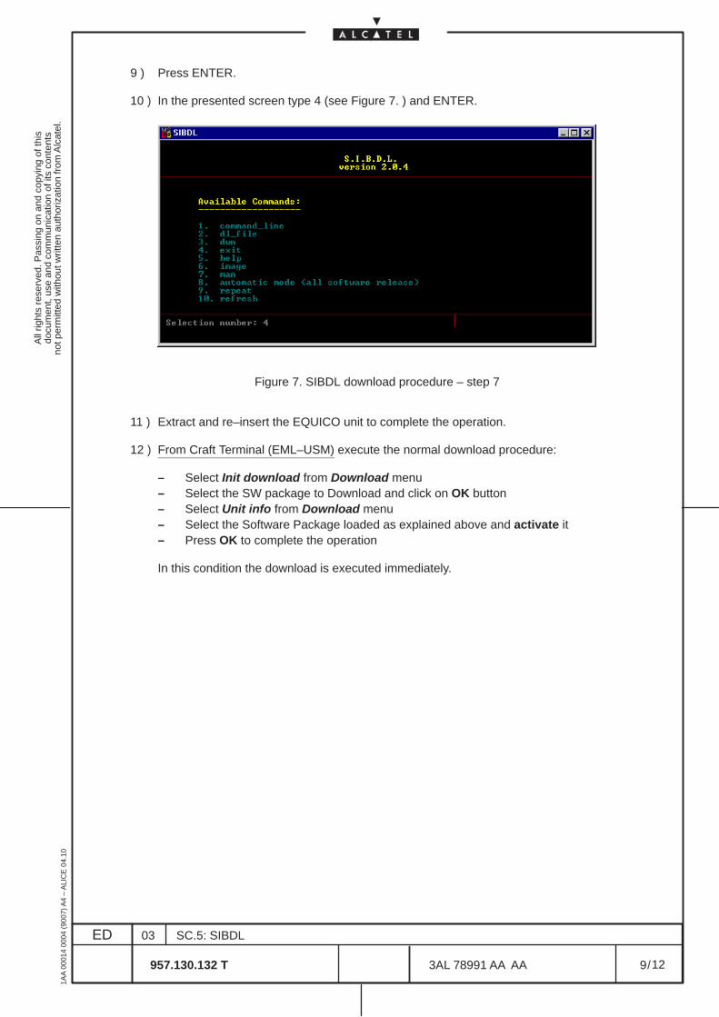
All
right
s re
serv
ed. P
assi
ng o
n an
d co
pyin
g of
this
docu
men
t, us
e an
d co
mm
unic
atio
n of
its
cont
ents
not p
erm
itted
with
out w
ritte
n au
thor
izat
ion
from
Alc
atel
.
ED
1AA
000
14 0
004
(900
7) A
4 –
ALI
CE
04.
10
9
03
957.130.132 T
SC.5: SIBDL
/3AL 78991 AA AA
12
12
9 ) Press ENTER.
10 ) In the presented screen type 4 (see Figure 7. ) and ENTER.
Figure 7. SIBDL download procedure – step 7
11 ) Extract and re–insert the EQUICO unit to complete the operation.
12 ) From Craft Terminal (EML–USM) execute the normal download procedure:
– Select Init download from Download menu– Select the SW package to Download and click on OK button– Select Unit info from Download menu– Select the Software Package loaded as explained above and activate it– Press OK to complete the operation
In this condition the download is executed immediately.

All
right
s re
serv
ed. P
assi
ng o
n an
d co
pyin
g of
this
docu
men
t, us
e an
d co
mm
unic
atio
n of
its
cont
ents
not p
erm
itted
with
out w
ritte
n au
thor
izat
ion
from
Alc
atel
.
ED
1AA
000
14 0
004
(900
7) A
4 –
ALI
CE
04.
10
10
03
957.130.132 T
SC.5: SIBDL
/3AL 78991 AA AA
12
12
All
right
s re
serv
ed. P
assi
ng o
n an
d co
pyin
g of
this
docu
men
t, us
e an
d co
mm
unic
atio
n of
its
cont
ents
not p
erm
itted
with
out w
ritte
n au
thor
izat
ion
from
Alc
atel
.
ED
1AA
000
14 0
004
(900
7) A
4 –
ALI
CE
04.
10
11
03
957.130.132 T
SC.5: SIBDL
/3AL 78991 AA AA
12
12
3 CONFIGURATION FOR SIBDL
3.1 Purpose of the procedure
This chapter describes the configurations to be performed for SIBDL operation.
3.1.1 Remote Access Service configuration
To install a new modem, the user should have administrator privileges and need the installation CD–ROMof Windows NT, then execute:
– Double click on ”My computer” icon on the PC desktop and double click on ”Control panel” icon;– double click on ”Network” icon;– select the folder ”Services” in the ”Network” window and push the button ”Add”: start the ”Select
Network Service” window;– select Remote Access Service (RAS) in the dialog box;– follow the instructions.
3.1.2 Serial Cable Modem configuration
To install a new modem, the user should have administrator privileges, then execute:
– Double click on ”My computer” icon on the PC desktop and double click on ”Control panel” icon;
– double click on ”Network” icon;select the folder ”Services” in the ”Network” window;
– select ”Remote Access Service” and push button ”Properties...”;
– push the button ”add” in ”Remote Access Setup” window;
– push the button ”Install Modem” in ”Add RAS Device” window: start the ”Install New Modem” window;
– put a tick against ”Don’t detect my modem; I will select him from a list” and push the ”Next > ” button;
– push the button ”Have disk...”: start the window Install from disk;
– push the button ”Browse...;search the folder where SIBDL is installed (Alcatel / SIBDL “version” / SIBDL /)and select the file”mdmalca.inf”, after push the button ”Open”;
– push the button ”OK” in window ”Install from disk”;select the modem named ”Serial cable” in the dialog box of window ”Install New Modem” and pushthe button ”Next >”;put a tick against ”Selected ports” and select only one port (the port must be available, i.e. not usedby another RAS modem) and push the button ”Next >”;
– follow the instructions;
– push the button ”OK” in ”Add RAS Device” window;
– push the button ”Continue” in ”Remote Access Setup” window;
– push the button ”OK” in ”Network” window;

All
right
s re
serv
ed. P
assi
ng o
n an
d co
pyin
g of
this
docu
men
t, us
e an
d co
mm
unic
atio
n of
its
cont
ents
not p
erm
itted
with
out w
ritte
n au
thor
izat
ion
from
Alc
atel
.
ED
1AA
000
14 0
004
(900
7) A
4 –
ALI
CE
04.
10
12
03
957.130.132 T
SC.5: SIBDL
/3AL 78991 AA AA
12
12
END OF DOCUMENT