Embed Size (px)
Citation preview
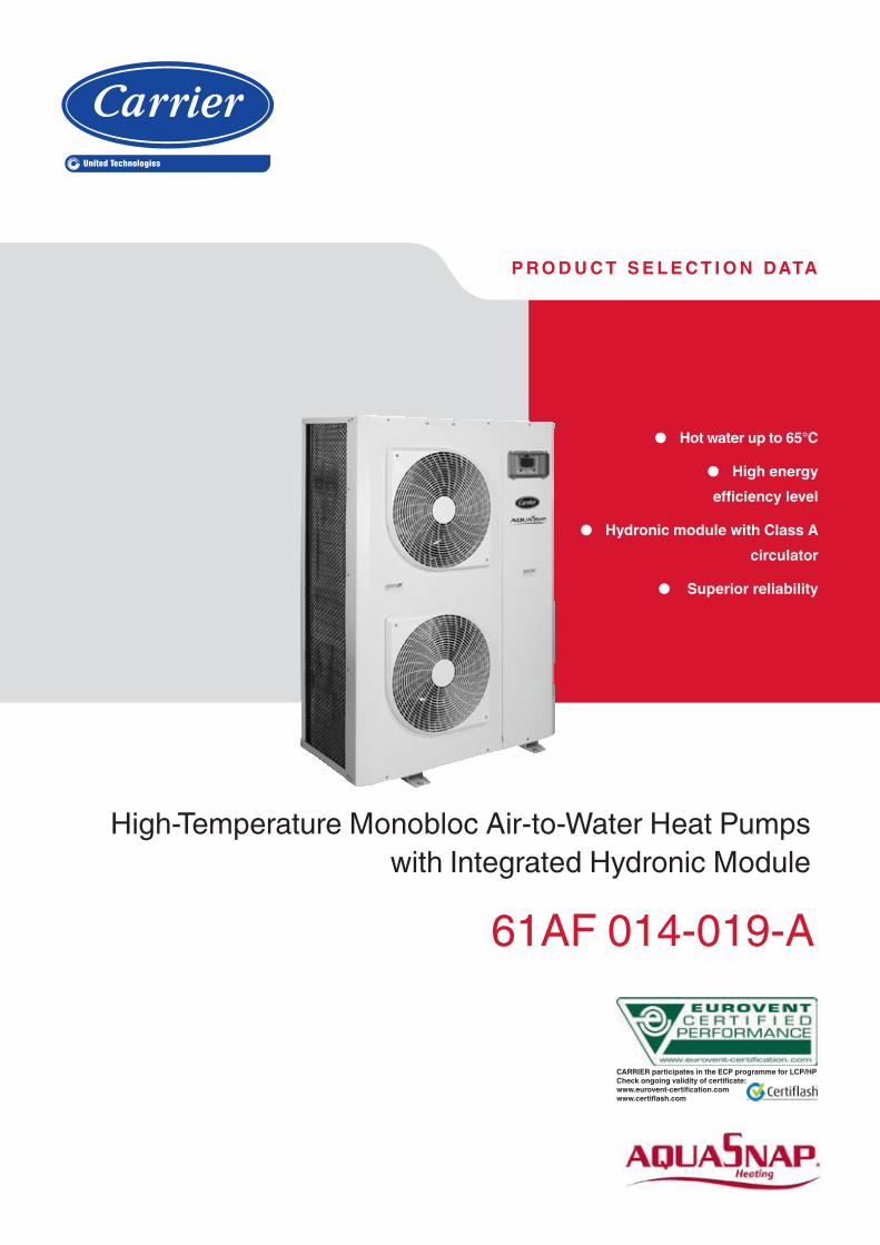
p r o d u c t s e l e c t i o n data
High-Temperature Monobloc Air-to-Water Heat Pumps
with Integrated Hydronic Module
61AF 014-019-A
● Hot water up to 65°c
● High energy
efficiency level
● Hydronic module with Class A circulator
● Superior reliability
CARRIER participates in the ECP programme for LCP/HPCheck ongoing validity of certificate:www.eurovent-certification.com www.certiflash.com

Easy and fast installation ■ Integrated hydronic module (option)
- Variable speed water pump. - Water filter protects the water pump against circulating
debris (option). - Overpressure valve, set to 3 bar for the 61AF 014 and to
4 bar for the 61AF 019. - Thermal insulation and frost protection down to -20°C,
using an electric resistance heater. ■ Physical features
- The unit has a small footprint and a low height (1103 mm for the 61AF 014 and 1550 mm for the 61AF 019), allowing it to blend in with any architectural styles.
- The unit is enclosed by easily removable panels, covering all components (except condensers and fans).
■ Simplified electrical connections - Single power supply point with neutral. - Main disconnect switch with high trip capacity (standard
only for 61AF 019). - Transformer for safe 24 V control circuit supply included.
■ Fast commissioning - Systematic factory operation test before shipment. - Quick-test function for step-by-step verification of the
instruments, electrical components and motors.
Economical operation ■ Seasonnal heating performance optimized
- In accordance with standard EN 14825/2013 in average climate, the Seasonal Coeficent of performance (SCOP) reaches 2.83 for an energy label of A+.
- The electronic expansion device (EXV) allows operation at a lower condensing pressure (COP optimisation).
- Dynamic superheat management for better utilisation of the condenser surface.
■ Reduced maintenance costs - Maintenance-free scroll compressors with vapour injection. - Pro-Dialog+ control offers fast diagnosis of possible
incidents and their history.
Environmental care ■ Ozone-friendly R-407C refrigerant
- Chlorine-free refrigerant of the HFC group with zero ozone depletion potential.
- Very efficient - ensures an increased energy efficiency ratio (COP).
■ Leak-tight refrigerant circuit - Brazed refrigerant connections for increased leak-
tightness. - Reduction of leaks due to elimination of capillary tubes
(TXVs). - Verification of pressure transducers and temperature
sensors without transferring refrigerant charge.
61AF 014-019-A
Nominal heating capacity 14-20 kW
The Aquasnap high-temperature heat pump range was designed for commercial applications such as the heating of offices, apartments and hotels as well as domestic hot water production in new and refurbished buildings.
FeaturesThe main features of this product range are:
■ Energy savingsThe 61AF range is certified to the Eurovent energy efficiency class A with a coefficient of performance (COP) of over 4. This complies with the COP required by the Ecolabel certification.
■ Ease-of-installationThe high-temperature Aquasnap heat pumps incorporate a hydronic module with a variable speed pump, in option.
■ Easy integrationThe low noise levels of the 61AF heat pump and its very compact chassis reduce the noise disturbance from the unit.
■ Application flexibilityThe operating range allows outside temperatures down to -20°C and leaving water temperatures up to 65°C for domestic hot water applications.
■ Availability - Intelligent unit control permits unit operation in extreme
conditions, minimising unit shut-down times. - Hot water production at 65°C is available continuously.
Carrier quality is your guarantee for the safety and durability of the installation.
The high-temperature heat pump range incorporates the latest technological features: - scroll compressors with vapour injection - low-noise fans made of a composite material - auto-adaptative microprocessor control - electronic expansion valve - variable speed pump.
The high-temperature Aquasnap heat pumps can be equipped with a hydronic module that is integrated into the heat pump chassis, limiting the installation to straight-forward operations like the wiring and the connection of the hot water supply and return piping.
Quiet operation
■ Compressors - Low-noise scroll compressors with low vibration level. - The compressor assembly is installed on an independent
chassis and supported by anti-vibration mountings. - Dynamic suction and discharge piping supports,
minimising vibration transmission (Carrier patent). ■ Evaporator section
- Vertical evaporator coils - Protection grilles on anti-vibration mountings to protect
the heat exchanger against possible shocks. - Latest-generation low-noise Flying Bird fans are now even
quieter and do not generate intrusive low-frequency noise. - Rigid fan installation for reduced start-up noise.
2

Superior reliability ■ State-of-the-art concept
- Cooperation with specialist laboratories and use of limit simulation tools (fi nite element calculations) for the design of the critical components, e.g. motor supports, suction/discharge piping etc.
■ Auto-adaptive control - Control algorithm prevents excessive compressor
cycling. ■ Exceptional endurance tests
- Corrosion resistance tests in salt mist in the laboratory. - Accelerated ageing test on components that are
submitted to continuous operation: compressor piping, fan supports.
- Transport simulation test in the laboratory on a vibrating table.
Pro-Dialog+ controlPro-Dialog+ combines intelligence with operating simplicity. The control constantly monitors all machine parameters and precisely manages the operation of compressors, expansion devices, fans and of the condenser water pump for optimum energy effi ciency.
■ Energy management - Seven-day internal time schedule clock: permits unit on/
off control and operation at a second set point. - Set point reset based on the outside air temperature or
the return water temperature or on the water heat exchanger delta T.
- Master/slave control of two heat pumps operating in parallel with operating time equalisation and automatic change-over in case of a unit fault (option).
- Start/stop based on the outside air temperature. ■ Ease-of-use
- The new backlighted LCD interface includes a manual control potentiometer to ensure legibility under any lighting conditions.
- The information is displayed clearly in English, French, German, Italian and Spanish (for other languages please consult Carrier).
- The Pro-Dialog+ navigation uses intuitive tree-structure menus, similar to the Internet browers. They are user-friendly and permit quick access to the principal operat-ing parameters: number of compressors operating, suction/discharge pressure, compressor operating hours, set point, air temperature, entering/leaving water temperature.
- As standard the unit includes a board for the control of a boiler and four electric resistance heater stages.
PRO-DIALOGPRO-DIALOGPRO-DIALOGPRO-DIALOGPRO-DIALOGPRO-DIALOGPRO-DIALOGPRO-DIALOGPRO-DIALOGPRO-DIALOGPRO-DIALOGPRO-DIALOGPRO-DIALOGPRO-DIALOGPRO-DIALOG
Remote operating mode with volt-free contacts (standard)
A simple two-wire communication bus between the RS485 port of the Aquasnap high-temperature heat pumps and the Carrier Comfort Network offers multiple remote control, monitoring and diagnostic possibilities.
Carrier offers a vast choice of control products, specially designed to control, manage and supervise the operation of a heating system. Please consult your Carrier representative for more information on these products. - Start/stop: opening of this contact will shut down the
heat pump. - Dual set point: closing of this contact activates a second
heating set point (example: unoccupied mode). - Demand limit: closing of this contact limits the maximum
heat pump capacity to a predefi ned value. - User safety: this contact is connected in series with the
water fl ow switch and can be used for any customer safety loop.
- Water pump control. - Alert indication: this volt-free contact indicates the
presence of a minor fault. - Alarm indication: this volt-free contact indicates the
presence of a major fault that has led to the shut-down of the refrigerant circuit.
Remote interface (accessory)This accessory includes a box that can be mounted inside the building. The power supply is provided via a 220 V/24 V transformer supplied. This interface allows access to the same menus as the unit interface and can be installed up to 300 m from the 61AF unit.
Pro-Dialog+ operator interface
3
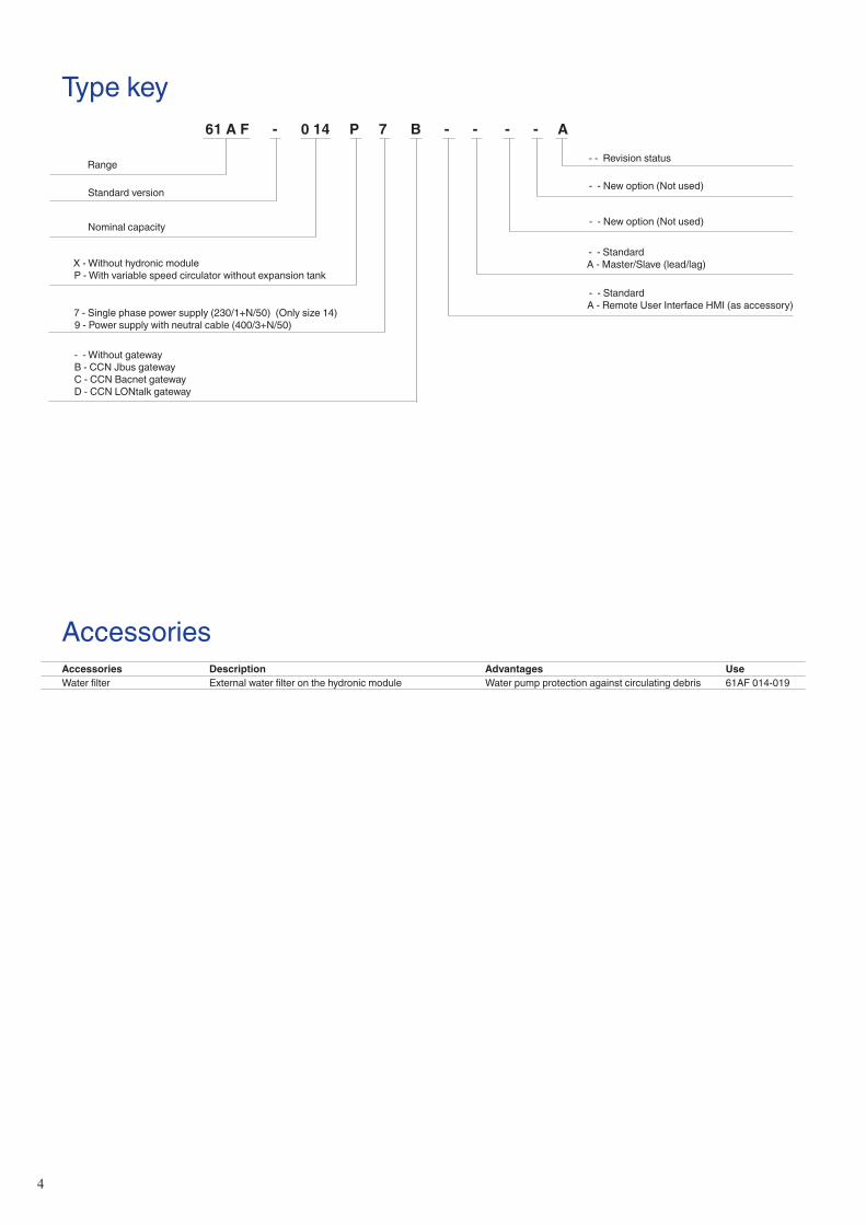
AccessoriesAccessories Description Advantages UseWater filter External water filter on the hydronic module Water pump protection against circulating debris 61AF 014-019
Range
61 A F - 0 14 P 7 B - - - - A
Standard version
X - Without hydronic module
P - With variable speed circulator without expansion tank
- - Standard
A - Remote User Interface HMI (as accessory)
- - New option (Not used)
- - New option (Not used)
- - Revision status
- - Without gateway
B - CCN Jbus gateway
C - CCN Bacnet gateway
D - CCN LONtalk gateway
Type key
7 - Single phase power supply (230/1+N/50) (Only size 14)
9 - Power supply with neutral cable (400/3+N/50)
- - Standard
A - Master/Slave (lead/lag)
Nominal capacity
4

Hydronic module (option)
The hydronic module option reduces the installation time. The heat pump is factory-equipped with the main hydronic components required for the installation: screen filter, water pump, relief valve, water pressure transducer, flow switch. The Pro-Dialog+ control allows integration of system and water pump protection devices (insufficient water flow rate).
The pump supplied with the hydronic module is a variable speed pump. With variable speed flow, the system no longer requires the control valve at the unit outlet.
Physical and electrical data, units with hydronic module 61AF 014-7 014-9 019operating weight*
Unit with hydronic module kg 169 169 216
Hydronic moduleMaximum operating pressure kPa 300 300 400
PumpsWater pump Variable speed circulator
Power input** kW 0.13 0.13 0.13
Maximum current draw *** A 1.1 1.1 1.1
Water connections (with hydronic module)Connections inch 1 female 1 female 1 male in/1-1/4 male out
Outside diameter mm 25 25 25 in/32 out
* Weight shown is a guideline only. To find out the unit refrigerant charge, please refer to the unit nameplate. ** To obtain the maximum power input for a unit with hydronic module, add the maximum unit power input to the pump power input. *** To obtain the maximum operating current draw for a unit with hydronic module, add the maximum unit current draw to the pump current draw.
Hydronic module 61AF 014
However, for applications with two-way valves a bypass system must be kept to guarantee the minimum flow rate.Pro-Dialog+ includes two operating modes:- Constant pump speed - Constant delta T control.
An automatic pump start-up algorithm protects the heatexchanger and the hydronic module piping against frostdown to -10°C outside air temperature, as standard. Ifnecessary, increased frost protection down to -20 °C ispossible by adding heaters to the hydronic module piping.
The hydronic module option is integrated into the heat pump without increasing its dimensions and saves the space normally used for the water pump.
Hydronic module 61AF 019
legend
1 Air purge
2 Water pump
3 Brazed plate heat exchanger
4 Water pressure gauge
5 Water pressure gauge
6 Flow switch
7 Water drain
legend
1 Air purge
2 Water pump
3 Brazed plate heat exchanger
4 Water pressure gauge
5 Water pressure gauge
6 Flow switch
7 Water drain
5
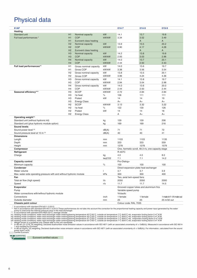
Physical data61AF 014-7 014-9 019-9Heating
Standard unit H1 Nominal capacity kW 14.1 13.7 19.8
Full load performances * H1 COP kW/kW 3.34 3.52 3.49
H1 Eurovent class heating A A
H2 Nominal capacity kW 13.9 13.5 20.2
H2 COP kW/kW 3.90 4.17 4.28
H2 Eurovent class heating A A
H3 Nominal capacity kW 14.2 13.8 19.8
H3 COP kW/kW 2.93 3.03 2.96
H4 Nominal capacity kW 14.0 13.7 20.1
H4 COP kW/kW 2.44 2.50 2.43
Full load performances** H1 Gross nominal capacity kW 14.0 13.6 19.7
H1 Gross COP kW/kW 3.38 3.56 3.54
H2 Gross nominal capacity kW 13.8 13.5 20.1
H2 Gross COP kW/kW 3.96 4.24 4.36
H3 Gross nominal capacity kW 14.1 13.8 19.7
H3 COP kW/kW 2.94 3.04 2.98
H4 Gross nominal capacity kW 14.0 13.6 20.0
H4 COP kW/kW 2.44 2.50 2.44
Seasonal efficiency*** H3 SCOP kW/kW 2.72 2.84 2.84
H3 Ƞs heat % 106 111 111
H3 Prated kW 14 14 19
H3 Energy Class A+ A+ A+
H2 SCOP kW/kW 3.13 3.32 3.22
H2 Ƞs heat % 122 130 126
H2 Prated kW 14 14 18
H2 Energy Class A A+ A+
operating weight(1)
Standard unit (without hydronic kit) kg 159 159 206
Standard unit (plus hydronic module option) kg 169 169 216
Sound levelsSound power level (2) dB(A) 71 71 72
Sound pressure level at 10 m (3) dB(A) 40 40 41
DimensionsLength mm 1103 1103 1135
Depth mm 333 333 559
Height mm 1278 1278 1579
Compressor One, hermetic scroll, 48.3 r/s, one capacity stageRefrigerant R-407C
Charge kg 4.0 4.0 8.0
teqCO2 7.1 7.1 14.2
Capacity control Pro-Dialog+
Minimum capacity % 100 100 100
Condenser Direct-expansion plate heat exchanger
Water volume l 3.7 3.7 3.9
Max. water-side operating pressure with and without hydronic module kPa 300 300 400
Fan Two, axial twin-speed fansTotal air flow (high speed) l/s 2050 2050 2000
Speed r/s 11.7 11.7 14.5
Evaporator Grooved copper tubes and aluminium finsPump Variable speed pump
Water connections with/without hydronic module Victaulic
Connections inch 1 female 1 female 1 male in/1-1/4 male out
Outside diameter mm 25 25 25 in/32 out
Chassis paint colour Colour code: RAL 7035
* In accordance with standard EN14511-3:2013 ** Not in accordance with standard EN14511-3:2013.These performances do not take into account the correction for the proportionnal heating capacity and power input generated by the water
pump to overcome the internal pressure drop in the heat exchanger. *** In accordance with standard EN14825:2013, average climate H1 Heating mode conditions: water heat exchanger water entering/leaving temperature 40°C/45°C, outside air temperature 7°C db/6°C wb, evaporator fooling factor 0 m².K/W H2 Heating mode conditions: water heat exchanger water entering/leaving temperature 30°C/35°C, outside air temperature 7°C db/6°C wb, evaporator fooling factor 0 m².K/W H3 Heating mode conditions: water heat exchanger water entering/leaving temperature 47°C/55°C, outside air temperature 7°C db/6°C wb, evaporator fooling factor 0 m².K/W H4 Heating mode conditions: water heat exchanger water entering/leaving temperature 55°C/65°C, outside air temperature 7°C db/6°C wb, evaporator fooling factor 0 m².K/W (1) Weight shown is a guideline only. Please refer to the unit nameplate (2) In dB ref=10-12 W, (A) weighting. Declared dualnumber noise emission values in accordance with ISO 4871 (with an associated uncertainty of +/-3dB(A)). Measured in accordance with ISO 9614-
1 and certified by Eurovent. (3) In dB ref 20µPa, (A) weighting. Declared dualnumber noise emission values in accordance with ISO 4871 (with an associated uncertainty of +/-3dB(A)). For information, calculated from the sound
power level Lw(A). Certifié Eurovent.
Eurovent certified values
6

Electrical dataWithout pump With pump
61AF - standard unit 014-7 014-9 019 014-7 014-9 019Power circuitNominal power supply V-ph-Hz 230-1-50 400-3-50 400-3-50 230-1-50 400-3-50 400-3-50
Voltage range V 207-253 360-440 360-440 207-253 360-440 360-440
Control circuit supply 24 V, via internal transformer 24 V, via internal transformerMaximum start-up current (Un)*Standard unit A - 66 102 - 67 103
Unit with electronic starter option A 47 - - 48 - -
Unit power factor at maximum capacity** 0.82 0.82 0.82 0.82 0.82 0.82
Maximum unit power input** kW 6.4 5.9 8.8 6.5 6.0 8.9
Nominal unit current draw*** A 22.9 7.9 12.4 24.0 9.0 13.5
Maximum unit current draw (Un)**** A 30.7 10.8 16.0 31.8 11.9 17.1
Maximum unit current draw (Un-10%)† A 36.4 11.9 16.6 37.5 13.0 17.7
* Maximum instantaneous start-up current (maximum operating current of the compressor + fan current + locked rotor current of the compressor). ** Power input, compressor and fan, at the unit operating limits (saturated suction temperature 10°C, saturated condensing temperature 65°C) and nominal voltage of 400 V (data given on the unit
nameplate). *** Standardised Eurovent conditions: condenser entering/leaving water temperature = 40°C/45°C, outside air temperature db/wb = 7°C/6°C. **** Maximum unit operating current at maximum unit power input and 400 V (values given on the unit nameplate). † Maximum unit operating current at maximum unit power input and 360 V.
Electrical data and operating conditions notes:• 61AF 014-019 units have a single power connection point located immediately
upstream of the main disconnect switch.
• The control box includes the following standard features: - a main disconnect switch (size 019 only), - starter and motor protection devices for the compressor, the fan and the
pump, - the control devices.
• Field connections: All connections to the system and the electrical installations must be in full
accordance with all applicable local codes.• The Carrier 61AF units are designed and built to ensure conformance
with these codes. The recommendations of European standard EN 60204-1 (machine safety - electrical machine components - part 1: general regulations - corresponds to IEC 60204-1) are specifically taken into account, when designing the electrical equipment.
Notes: • Generally the recommendations of IEC 60364 are accepted as compliance
with the requirements of the installation directives. Conformance with EN
60204-1 is the best means of ensuring compliance with the Machinery
Directive § 1.5.1.
• Annex B of EN 60204-1 describes the electrical characteristics used for the operation of the machines.
• The operating environment for the 61AF units is specified below:1. Environment* - Environment as classified in EN 60721 (corresponds to
IEC 60721):
- outdoor installation*
- ambient temperature range: -20°C to +40°C, class 4K4H - altitude: ≤ 2000 m - presence of hard solids, class 4S2 (no significant dust present) - presence of corrosive and polluting substances, class 4C2 (negligible)2. Power supply frequency variation: ± 2 Hz.
3. The neutral (N) conductor must not be connected directly to the unit (if
necessary use a transformer).
4. Overcurrent protection of the power supply conductors is not provided with
the unit.
5. The factory-installed disconnect switch is of a type suitable for power
interruption in accordance with EN 60947-3 (corresponds to IEC 60947-3)
6. The units are designed for connection to TN networks (IEC 60364). For IT
networks the earth connection must not be at the network earth. Provide a
local earth, consult competent local organisations to complete the electrical installation.
Caution: If particular aspects of an actual installation do not conform to the conditions described above, or if there are other conditions which should be considered, always contact your local Carrier representative.
* The required protection level for this class is IP43BW (according to reference
document IEC 60529). All 61AF units are protected to IP44CW and fulfil this protection condition.
7
20
25
30
35
40
45
50
55
60
65
70
-25 -20 -15 -10 -5 0 5 10 15 20 25 30 35 40 45
Entering air temperature, °C
Leav
ing w
ater te
mpera
ture,
°C
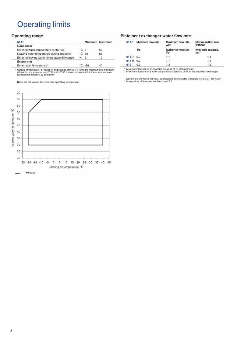
Plate heat exchanger water flow rate61AF Minimum flow rate Maximum flow rate
withMaximum flow rate without
l/s hydronic module, l/s*
hydronic module, l/s**
014-7 0.2 1.1 1.1
014-9 0.2 1.1 1.1
019 0.3 1.3 1.6
* Maximum flow rate at an available pressure of 15 kPa minimum. ** Maximum flow rate at a water temperature difference of 3K in the plate heat exchanger.
Note: For a domestic hot water application (leaving water temperature = 65°C), the water temperature difference must be at least 8 K.
Full load
operating range
61AF Minimum MaximumCondenserEntering water temperature at start-up °C 8 57
Leaving water temperature during operation °C 30 65
Entering/leaving water temperature difference K 3 10
EvaporatorEntering air temperature* °C -20 40
* Outside temperature: For transport and storage of the 61AF units the minimum and maximum allowable temperatures are -20°C and +50°C. It is recommended that these temperatures are used for transport by container.
Note: Do not exceed the maximum operating temperature.
Operating limits
8
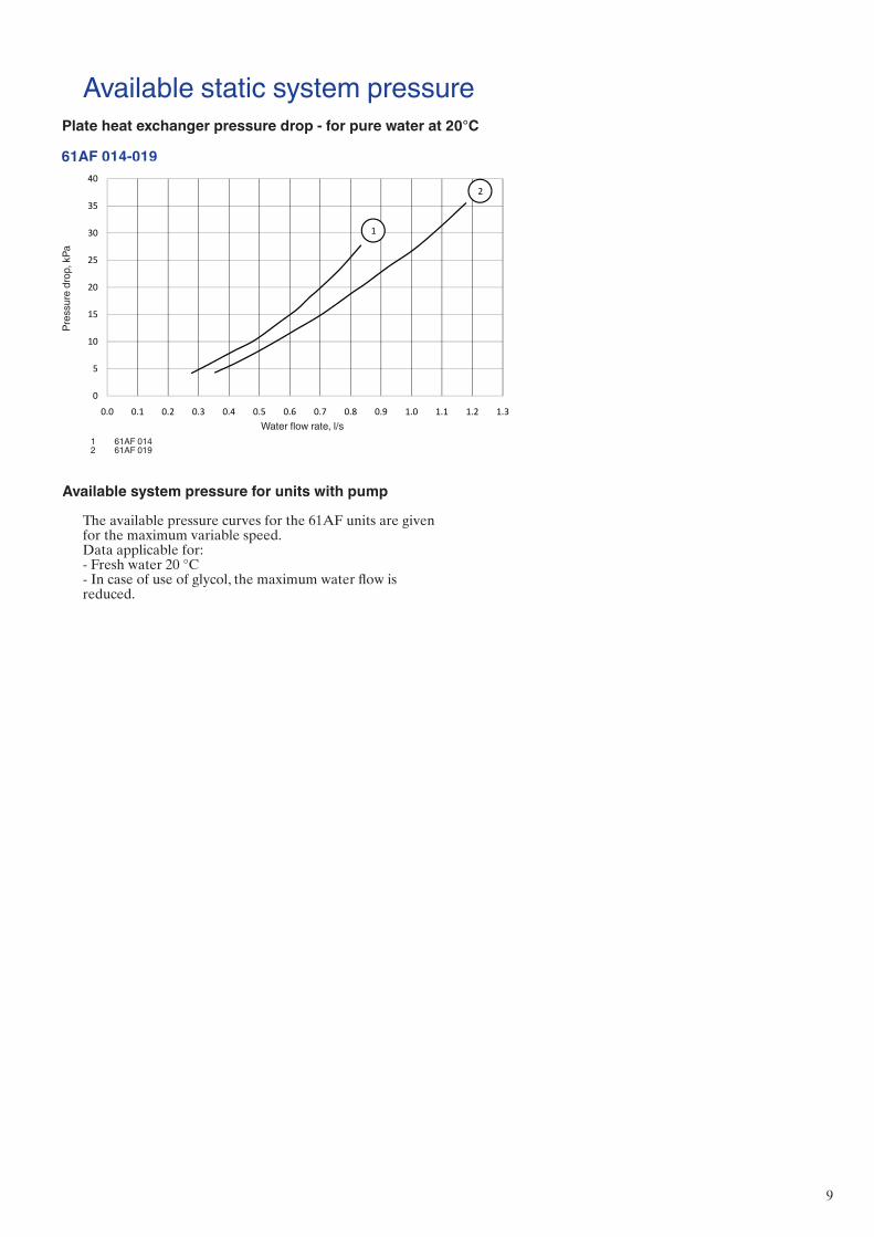
Available static system pressurePlate heat exchanger pressure drop - for pure water at 20°C
Water flow rate, l/s
Pres
sure
drop,
kPa
1 61AF 014 2 61AF 019
61AF 014-019
15
20
25
30
35
40
Pres
sure
Dro
p [k
Pa]
1
2
0
5
10
15
0.0 0.1 0.2 0.3 0.4 0.5 0.6 0.7 0.8 0.9 1.0 1.1 1.2 1.3
Pres
sure
Dro
p [k
Pa]
water flow rate [l/s]
Available system pressure for units with pump The available pressure curves for the 61AF units are given for the maximum variable speed. Data applicable for:- Fresh water 20 °C- In case of use of glycol, the maximum water flow is reduced.
9

Water flow rate, l/s
Avail
able
press
ure, k
Pa
Available system pressure for units with pump The available pressure curves for the 61AF units are given for the maximum variable speed. Data applicable for:- Fresh water 20 °C- In case of use of glycol, the maximum water flow is reduced.
61AF 014 61AF 019
Water flow rate, l/s
Avail
able
press
ure, k
Pa
10
20
30
40
50
60
70
80
0.2 0.3 0.4 0.5 0.6 0.7 0.8 0.9 1.0 1.1 1.2
014 - 100%
014 - 80%
014 - 50%
10
20
30
40
50
60
70
80
0.3 0.4 0.5 0.6 0.7 0.8 0.9 1.0 1.1 1.2 1.3
019 - 100%
019 - 80%
019 - 50%
10
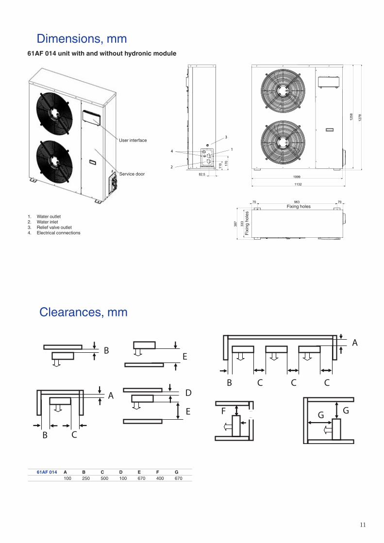
Dimensions, mm61AF 014 unit with and without hydronic module
61AF 014 a B c d e F G
100 250 500 100 670 400 670
Clearances, mm
82.5
110 170
96370 70
333
387
1099
1132
1258
1278
4
2
1
3
Fixing Holes
Fixing Holes
User interface
Service door
Fixing holes
Fix
ing
ho
les
B
B C
A D
E
E
B
F
C C C
GG
A
B
1. Water outlet
2. Water inlet
3. Relief valve outlet
4. Electrical connections
11
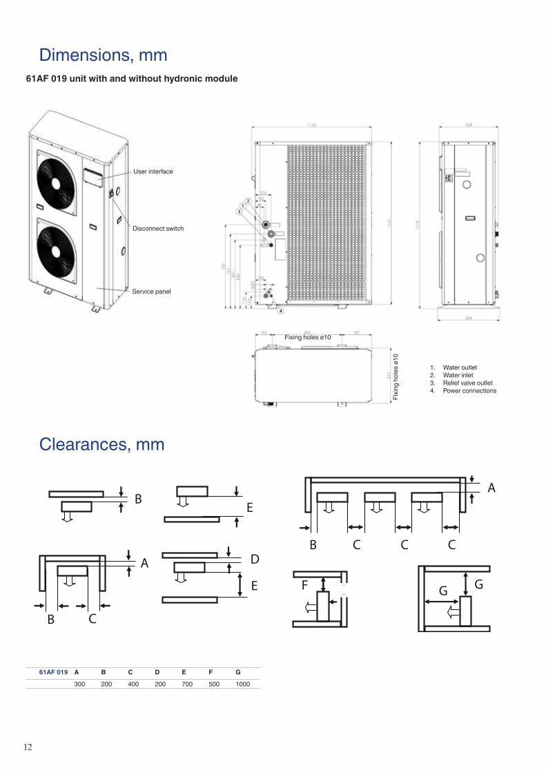
Dimensions, mm61AF 019 unit with and without hydronic module
61AF 019 a B c d e F G
300 200 400 200 700 500 1000
Fixing holes ø10
Fix
ing
ho
les
ø1
0
1. Water outlet
2. Water inlet
3. Relief valve outlet
4. Power connections
B
B C
A D
E
E
B
F
C C C
GG
A
B
Clearances, mm
Service panel
Disconnect switch
User interface
12

61AF 014-019Outside air dry-bulb (wet-bulb) temperature, °C-20 (-20,5) / 64.2% RH -15 (-16) / 52.2% RH -10 (-11) / 66.6% RH -7 (-8) / 72.5% RH 2 (1) / 83.8% RH 7 (6) / 86.8% RH
LWT Qh cop q Δp Qh cop q Δp Qh cop q Δp Qh cop q Δp Qh cop q Δp Qh cop q Δp°c kW kW/
kWl/s kPa kW kW/
kWl/s kPa kW kW/
kWl/s kPa kW kW/
kWl/s kPa kW kW/
kWl/s kPa kW kW/
kWl/s kPa
014-7 30 6.4 2.15 0.31 4.5 7.6 2.46 0.36 6.0 8.4 2.69 0.43 7.9 8.7 2.77 0.47 9.2 10.9 3.43 0.61 14.4 13.8 4.20 0.66 16.5
014-9 6.0 2.29 0.29 4.0 7.2 2.64 0.34 5.5 8.0 2.88 0.41 7.3 8.4 2.97 0.45 8.6 10.6 3.69 0.59 13.7 13.5 4.54 0.64 15.7
019-9 9.5 2.36 0.45 6.6 11.0 2.70 0.53 8.7 11.6 2.83 0.62 11.3 11.4 2.80 0.67 13.1 14.0 3.44 0.86 20.1 20.5 4.71 0.98 25.2
014-7 35 6.4 2.02 0.31 4.4 7.6 2.31 0.36 5.9 8.4 2.51 0.43 7.7 8.7 2.58 0.47 9 10.9 3.18 0.61 14 13.9 3.90 0.66 16.2
014-9 6.0 2.14 0.29 4.0 7.2 2.45 0.35 5.4 8.0 2.67 0.41 7.1 8.4 2.74 0.45 8.4 10.6 3.37 0.59 13.3 13.5 4.17 0.65 15.5
019-9 9.4 2.20 0.45 6.4 11.0 2.49 0.53 8.4 11.6 2.62 0.61 10.9 11.5 2.61 0.67 12.6 14.1 3.19 0.85 19.2 20.2 4.28 0.97 24.0
014-7 40 6.4 1.90 0.31 4.3 7.6 2.16 0.37 5.7 8.4 2.33 0.43 7.5 8.7 2.39 0.47 8.8 10.8 2.92 0.61 13.6 14.0 3.62 0.67 16.0
014-9 6.1 2.00 0.29 3.9 7.2 2.28 0.35 5.3 8.0 2.46 0.41 7 8.3 2.52 0.45 8.2 10.5 3.08 0.59 12.9 13.6 3.83 0.65 15.3
019-9 9.3 2.04 0.45 6.2 10.9 2.30 0.53 8.2 11.6 2.43 0.61 10.5 11.6 2.43 0.66 12.2 14.2 2.96 0.84 18.5 20.0 3.87 0.96 23.1
014-7 45 6.4 1.80 0.31 4.3 7.6 2.03 0.37 5.6 8.4 2.17 0.43 7.3 8.7 2.22 0.47 8.5 10.8 2.68 0.6 13.2 14.1 3.34 0.68 15.9
014-9 6.1 1.86 0.29 3.9 7.2 2.12 0.35 5.2 8.0 2.27 0.41 6.8 8.3 2.32 0.45 8 10.5 2.80 0.59 12.5 13.7 3.52 0.66 15.2
019-9 9.4 1.90 0.45 6.1 10.9 2.13 0.53 8.0 11.7 2.25 0.61 10.3 11.8 2.27 0.66 11.9 14.5 2.73 0.84 18.1 19.8 3.49 0.95 22.3
014-7 50 6.5 1.70 0.31 4.2 7.6 1.90 0.37 5.6 8.4 2.04 0.43 7.2 8.8 2.08 0.47 8.4 10.7 2.46 0.6 12.8 14.2 3.09 0.68 15.8
014-9 6.2 1.75 0.30 3.9 7.3 1.97 0.35 5.2 8.1 2.11 0.41 6.7 8.4 2.16 0.45 7.9 10.4 2.55 0.58 12.2 13.8 3.22 0.67 15.1
019-9 9.4 1.78 0.45 6.1 11.0 1.97 0.53 7.9 11.8 2.08 0.61 10.2 12.0 2.10 0.67 11.8 14.7 2.52 0.84 17.7 19.8 3.15 0.95 21.9
014-7 55 + + + + 7.7 1.80 0.23 2.5 8.4 1.94 0.27 3.2 8.9 1.99 0.29 3.7 10.6 2.31 0.38 5.7 14.2 2.93 0.43 7.1
014-9 + + + + 7.3 1.85 0.22 2.3 8.2 2.00 0.26 3 8.6 2.05 0.28 3.5 10.3 2.38 0.36 5.4 13.8 3.03 0.42 6.8
019-9 + + + + 11.1 1.86 0.34 3.5 11.9 1.97 0.39 4.5 12.1 1.99 0.42 5.2 15.0 2.41 0.53 7.8 19.8 2.96 0.60 9.6
014-7 60 + + + + 8.6 1.82 0.22 2.2 9.0 1.87 0.24 2.6 10.6 2.13 0.3 3.8 14.1 2.69 0.34 4.7
014-9 + + + + 8.3 1.87 0.21 2.1 8.7 1.92 0.23 2.4 10.3 2.18 0.29 3.6 13.7 2.77 0.33 4.5
019-9 + + + + 12.2 1.84 0.31 3.1 12.4 1.86 0.34 3.6 15.4 2.25 0.43 5.3 19.9 2.70 0.48 6.5
014-7 65 8.8 1.70 0.22 2.2 9.2 1.75 0.24 2.6 10.6 1.94 0.3 3.8 14.0 2.44 0.34 4.6
014-9 8.4 1.74 0.21 2.1 8.9 1.79 0.23 2.4 10.3 1.98 0.29 3.6 13.7 2.50 0.33 4.4
019-9 12.5 1.71 0.32 3.2 12.8 1.74 0.35 3.6 15.9 2.08 0.43 5.3 20.1 2.43 0.49 6.5
Heating capacities in accordance with EN14511-3 : 2013
legend LWT Leaving water temperature, °C Qh Heating capacity, kW cop Coefficient of performance, kW/kW q Condenser water flow rate, l/s Δp Condenser pressure drop, kPa + Lower temperature difference required for selected LWT
Application data Standard units, refrigerant: R-407C Condenser entering/leaving water temperature difference: 5 K for LWT values <55°C Condenser entering/leaving water temperature difference: 8 K for LWT values = 55°C Condenser entering/leaving water temperature difference: 10 K for LWT values >55°C Condenser fluid: water Fouling factor: 0 (m2 K)/W Performances in accordance with EN14511-3:2013.
13

Heating capacities in accordance with EN14511-3 : 2011
61AF 014-019Outside air dry-bulb (wet-bulb) temperature, °C12 (11) / 88.9% RH 15 (14) / 89.9% RH 20 (19) / 91.2% RH 25 (24) / 92.1% RH 30 (29) / 92.9% RH 35 (34) / 83.8% RH
LWT Qh cop q Δp Qh cop q Δp Qh cop q Δp Qh cop q Δp Qh cop q Δp Qh cop q Δp°c kW kW/
kWl/s kPa kW kW/
kWl/s kPa kW kW/
kWl/s kPa kW kW/
kWl/s kPa kW kW/
kWl/s kPa kW kW/
kWl/s kPa
014-7 30 15.2 4.51 0.72 19.2 16.0 4.69 0.76 21.0 17.2 4.96 0.82 23.8 17.9 5.11 0.85 25.4 18.6 5.24 0.89 27.0 19.2 5.38 0.92 28.7
014-9 14.7 4.90 0.70 18.3 15.5 5.11 0.74 20.0 16.8 5.45 0.80 22.9 17.5 5.62 0.83 24.4 18.1 2.79 0.87 26.0 18.8 5.95 0.90 27.6
019-9 22.2 5.01 1.06 28.8 22.3 5.04 1.06 29.1 22.5 5.08 1.07 29.5 22.7 5.12 1.08 29.9 22.8 5.16 1.09 30.3 23.0 5.20 1.10 30.7
014-7 35 15.2 4.18 0.73 18.8 16.0 4.35 0.76 20.5 17.3 4.63 0.83 23.6 18.0 4.77 0.86 25.2 18.7 4.89 0.89 26.7 19.4 5.02 0.93 28.4
014-9 14.8 4.48 0.71 18.0 15.6 4.68 0.74 19.6 16.9 5.00 0.81 22.6 17.6 5.17 0.84 24.2 18.3 5.32 0.87 25.8 18.9 5.47 0.91 27.3
019-9 22.2 4.61 1.06 28.2 22.6 4.69 1.08 29.1 22.8 4.73 1.09 29.5 23.0 4.76 1.10 30.0 23.2 4.80 1.11 30.4 23.3 4.83 1.12 30.8
014-7 40 15.2 3.86 0.73 18.5 16.0 4.01 0.77 20.1 17.3 4.26 0.83 23.1 18.2 4.42 0.87 25.0 18.9 4.54 0.90 26.6 19.5 4.65 0.94 28.2
014-9 14.8 4.10 0.71 17.7 15.6 4.27 0.75 19.3 16.9 4.56 0.81 22.1 17.8 4.75 0.85 24.1 18.5 4.88 0.88 25.6 19.1 5.02 0.92 27.2
019-9 22.2 4.22 1.07 27.7 23.0 4.33 1.10 29.4 23.2 4.37 1.11 29.8 23.4 4.40 1.12 30.2 23.6 4.43 1.13 30.6 23.7 4.46 1.14 31.0
014-7 45 15.2 3.55 0.73 18.2 16.0 3.68 0.77 19.8 17.4 3.91 0.83 22.7 18.4 4.07 0.88 25.0 19.1 4.18 0.92 26.6 19.8 4.29 0.95 28.2
014-9 14.9 3.75 0.71 17.4 15.6 3.90 0.75 19.0 16.9 4.15 0.81 21.7 18.0 4.35 0.86 24.1 18.7 4.47 0.90 25.6 19.3 4.59 0.93 27.2
019-9 22.4 3.84 1.07 27.5 23.2 3.95 1.11 29.3 23.7 4.01 1.13 30.3 23.9 4.04 1.15 30.7 24.0 4.07 1.15 31.1 24.2 4.10 1.16 31.5
014-7 50 15.3 3.26 0.74 17.9 16.1 3.38 0.77 19.5 17.4 3.58 0.84 22.3 18.7 3.76 0.90 25.1 19.4 3.85 0.93 26.7 20.0 3.94 0.96 28.3
014-9 14.9 3.42 0.72 17.2 15.7 3.55 0.75 18.7 17.0 3.77 0.82 21.4 18.3 3.98 0.88 24.2 18.9 4.09 0.91 25.7 19.6 4.19 0.94 27.2
019-9 22.3 3.44 1.07 26.7 23.5 3.58 1.13 29.3 24.3 3.67 1.16 31.0 24.4 3.70 1.17 31.4 24.6 3.72 1.18 31.8 24.8 3.75 1.19 32.2
014-7 55 15.3 3.10 0.46 8.0 16.0 3.22 0.48 8.7 17.4 3.41 0.52 10.0 18.8 3.61 0.57 11.3 19.4 3.70 0.59 12.1 20.1 3.79 0.61 12.8
014-9 14.9 3.23 0.45 7.7 15.7 3.36 0.47 8.4 17.0 3.57 0.51 9.6 18.3 3.79 0.55 10.9 19.0 3.91 0.57 11.6 19.7 4.02 0.59 12.3
019-9 22.2 3.25 0.67 11.7 23.5 3.41 0.71 13.0 24.5 3.53 0.74 13.9 24.7 3.55 0.75 14.1 24.9 3.58 0.75 14.3 25.1 3.60 0.76 14.5
014-7 60 15.4 2.88 0.37 5.5 16.1 2.98 0.39 5.9 17.4 3.16 0.42 6.8 18.8 3.34 0.45 7.7 19.7 3.45 0.48 8.3 20.4 3.54 0.49 8.8
014-9 15.0 2.98 0.36 5.3 15.7 3.08 0.38 5.7 17.0 3.28 0.41 6.5 18.3 3.48 0.44 7.4 19.3 3.62 0.47 8.1 19.9 3.72 0.48 8.5
019-9 22.2 2.96 0.54 7.9 23.7 3.12 0.57 8.8 25.2 3.27 0.61 9.8 25.3 3.29 0.61 9.9 25.5 3.31 0.62 10.0 25.7 3.33 0.62 10.1
014-7 65 15.6 2.64 0.38 5.5 16.2 2.72 0.39 5.9 17.5 2.87 0.42 6.7 18.8 3.03 0.46 7.6 20.0 3.17 0.49 8.5 20.7 3.24 0.50 9.0
014-9 15.2 2.71 0.37 5.3 15.9 2.80 0.38 5.7 17.1 2.97 0.41 6.5 18.4 3.14 0.45 7.3 19.6 3.30 0.48 8.2 20.3 3.38 0.49 8.6
019-9 22.4 2.65 0.54 7.9 23.9 2.78 0.58 8.8 25.7 2.94 0.62 10.0 26.3 2.99 0.64 10.3 26.5 3.01 0.64 10.5 26.6 3.03 0.65 10.6
legend LWT Leaving water temperature, °C Qh Heating capacity, kW cop Coefficient of performance, kW/kW q Condenser water flow rate, l/s Δp Condenser pressure drop, kPa
Application data Standard units, refrigerant: R-407C Condenser entering/leaving water temperature difference: 5 K for LWT values <55°C Condenser entering/leaving water temperature difference: 8 K for LWT values = 55°C Condenser entering/leaving water temperature difference: 10 K for LWT values >55°C Condenser fluid: water Fouling factor: 0 (m2 K)/W Performances in accordance with EN14511-3:2013.
14

Order No.: 16114-20, 11.2015. Supersedes order No.: 16114-20, 04.2014. Manufactured by: Carrier SCS, Montluel, FranceManufacturer reserves the right to change any product specifications without notice. Printed in the European Union