Embed Size (px)
Citation preview

04/19/23 CSE1303 Part B lecture notes 1
Hardware Hardware ImplementationImplementation
Lecture B1Lecture B177
Lecture notes section B1Lecture notes section B177

04/19/23 CSE1303 Part B lecture notes 2
Last timeLast time
Analysis of translationAnalysis of translation Writing efficient CWriting efficient C

04/19/23 CSE1303 Part B lecture notes 3
In this lectureIn this lecture
GatesGates Combinatorial logicCombinatorial logic
adderadder ALUALU
Sequential logicSequential logic flip-flopflip-flop memorymemory
CPUCPU fetch-decode-execute cyclefetch-decode-execute cycle

04/19/23 CSE1303 Part B lecture notes 4
How to make a computerHow to make a computer
Computers are electronic Computers are electronic equipmentequipment contain many connected electronic contain many connected electronic
componentscomponents• memorymemory• Central Processing Unit (Central Processing Unit (CPUCPU))• specialized devices (network, video, etc.)specialized devices (network, video, etc.)
components largely made of circuits components largely made of circuits containing wires and containing wires and gatesgates

04/19/23 CSE1303 Part B lecture notes 5
GatesGates
Tiny electronic switchesTiny electronic switches made of transistorsmade of transistors implement implement Boolean logicBoolean logic
• 0/1 0/1 low/high voltage low/high voltage• digitaldigital
for given inputs, produce known for given inputs, produce known outputoutput• according to according to truth tabletruth table
represented in circuit diagrams by represented in circuit diagrams by symbolssymbols

04/19/23 CSE1303 Part B lecture notes 6
GatesGatesNOTNOT
In 1In 1 In 2In 2 OutOut
00 00 00
00 11 00
11 00 00
11 11 11
InIn OutOut
00 11
11 00
ANDAND
In 1In 1 In 2In 2 OutOut
00 00 00
00 11 11
11 00 11
11 11 11
OROR
In 1In 1 In 2In 2 OutOut
00 00 00
00 11 11
11 00 11
11 11 00
XORXOR

04/19/23 CSE1303 Part B lecture notes 7
Combinatorial logicCombinatorial logic
What about more complex truth What about more complex truth tables?tables?
Made by Made by combiningcombining many gates many gates togethertogether wires connect inputs and outputswires connect inputs and outputs each wire can carry only one bit, 0 or each wire can carry only one bit, 0 or
11

04/19/23 CSE1303 Part B lecture notes 8
Combinatorial logicCombinatorial logic
Circuits made from collections of Circuits made from collections of gatesgates outputs depend only on inputsoutputs depend only on inputs
• not on prior statenot on prior state
characterized by truth tablecharacterized by truth table comparable to Boolean expressioncomparable to Boolean expression

04/19/23 CSE1303 Part B lecture notes 9
Combinatorial logicCombinatorial logic
X = (A & ~B) | (B & C)X = (A & ~B) | (B & C)
AA BB CC XX
00 00 00 00
00 00 11 00
00 11 00 00
00 11 11 11
11 00 00 11
11 00 11 11
11 11 00 00
11 11 11 11
AA
BB
CC
XX
all three of formsall three of formsare equivalent; each can are equivalent; each can be converted to the other be converted to the other
two.two.
00
11
11
00
00
00
11
1111
11
00
11
boolean boolean expressionexpression
logic circuitlogic circuit truth tabletruth table

04/19/23 CSE1303 Part B lecture notes 10
Combinatorial logicCombinatorial logic
Many parts of a computer are Many parts of a computer are constructed of combinatorial logicconstructed of combinatorial logic adderadder circuit circuit
• performs additionperforms addition
arithmetic logic unit (arithmetic logic unit (ALUALU))• performs many kinds of arithmetic and performs many kinds of arithmetic and
bitwise logical operationsbitwise logical operations• contains adder circuitcontains adder circuit
multiplexer and decodermultiplexer and decoder• direct bit traffic between componentsdirect bit traffic between components

04/19/23 CSE1303 Part B lecture notes 11
AdderAdder
A combinatorial circuit that adds A combinatorial circuit that adds binary valuesbinary values according to this truth tableaccording to this truth table
In 1In 1 In 2In 2 SumSum CarryCarry
00 00 00 00
00 11 11 00
11 00 11 00
11 11 00 11
Sum is equivalent Sum is equivalent to XORto XOR
Carry is Carry is equivalent to equivalent to
ANDAND

04/19/23 CSE1303 Part B lecture notes 12
AdderAdder
In 1In 1
In 2In 2
CarryCarry
SumSum
This circuit can add two binary digits This circuit can add two binary digits and is called a and is called a half-adderhalf-adder

04/19/23 CSE1303 Part B lecture notes 13
AdderAdder
55
33
33
88
11
44++
11
11
Why “half-Why “half-adder”. . . ?adder”. . . ?
. . . because to add . . . because to add multi-digit numbers multi-digit numbers
each column requires each column requires twotwo additions additions
99

04/19/23 CSE1303 Part B lecture notes 14
Full adderFull adder
in 1in 1in 2in 2
sumsum
carry carry outout
carry carry inin half half
addersadders
This circuit is called This circuit is called a a full adderfull adder and can and can
add three binary add three binary digitsdigits
This OR gate This OR gate combines the combines the carries from carries from the two half-the two half-
addersadders

04/19/23 CSE1303 Part B lecture notes 15
Ripple-carry adderRipple-carry adderA0A0
out3out3 out2out2 out1out1 out0out0
B0B0A1A1
B1B1A2A2
B2B2A3A3
B3B3

04/19/23 CSE1303 Part B lecture notes 16
Ripple-carry adderRipple-carry adderA0A0
out3out3 out2out2 out1out1 out0out0
B0B0A1A1
B1B1A2A2
B2B2A3A3
B3B311
0000
1111
1100
00
01010101 + + 01100110 = = 10111011
11110011
00001100
110000
00
00
00
11
00
00

04/19/23 CSE1303 Part B lecture notes 17
Ripple-carry adderRipple-carry adder
So named because gate results So named because gate results (including carries) propagate (including carries) propagate (“ripple”) from LSB to MSB(“ripple”) from LSB to MSB right to leftright to left corresponds to how humans add corresponds to how humans add
numbers with pen and papernumbers with pen and paper More sophisticated, faster, adder More sophisticated, faster, adder
circuits exist that can create the circuits exist that can create the higher order carries more quicklyhigher order carries more quickly

04/19/23 CSE1303 Part B lecture notes 18
AdderAdder
++
Adders (and other Adders (and other arithmetic arithmetic
circuits) are circuits) are usually drawn like usually drawn like
this in block this in block diagramsdiagrams
A3-A0A3-A0 B3-B0B3-B0
out3-out0out3-out0
inputsinputs
outputoutputcollections of parallel, collections of parallel,
related wires like this are related wires like this are known as known as busesbuses; they carry ; they carry
multi-bit values between multi-bit values between componentscomponents

04/19/23 CSE1303 Part B lecture notes 19
ArithmeticArithmetic
Computers need to do more than Computers need to do more than just additionjust addition arithmetic: arithmetic: + – * / %+ – * / % logic: logic: & | ~ << >>& | ~ << >>
Need a circuit that can Need a circuit that can selectselect operation to performoperation to perform

04/19/23 CSE1303 Part B lecture notes 20
Arithmetic Logic Unit Arithmetic Logic Unit (ALU)(ALU)
++ ** && <<<< . . .. . .
MUXMUX
op op 00
op op 11
op op 22
op op 33
opop
outout
AA BB
MultiplexerMultiplexer: a : a combinatorial combinatorial circuit which circuit which
selects selects exactly one exactly one
inputinput
op selects operation:op selects operation:
0 = add, 1 = 0 = add, 1 = multiply, ...multiply, ...
more more operations operations
herehere
00 11 22 33 ....
04/19/23 CSE1303 Part B lecture notes 21
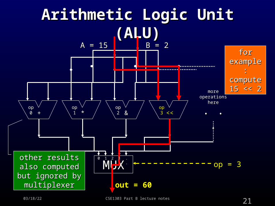
Arithmetic Logic Unit Arithmetic Logic Unit (ALU)(ALU)
++ ** && <<<< . . .. . .
MUXMUX
op op 00
op op 11
op op 22
op op 33
op = 3op = 3
out = 60out = 60
A = 15A = 15 B = 2B = 2
other results other results also computed also computed but ignored by but ignored by
multiplexermultiplexer
more more operations operations
herehere
for for example: example: compute compute 15 << 215 << 2
00 11 22 33 ....

04/19/23 CSE1303 Part B lecture notes 22
MemoryMemory
Computers need memory for storageComputers need memory for storage Different kinds of memory distinguished Different kinds of memory distinguished
by speed, size, cost and proximity to CPUby speed, size, cost and proximity to CPU main memorymain memory
• slowish, huge, cheap, far from CPUslowish, huge, cheap, far from CPU• typical size 10typical size 1099 bits bits
cachecache• fast, medium-sized, expensive, near to CPUfast, medium-sized, expensive, near to CPU• typical size 10typical size 1066 bits bits
registersregisters• extremely fast, tiny, very expensive, located on extremely fast, tiny, very expensive, located on
CPUCPU• in MIPS (32 GPRs)×32 bits = 1024 bitsin MIPS (32 GPRs)×32 bits = 1024 bits

04/19/23 CSE1303 Part B lecture notes 23
MemoryMemory
The The smallestsmallest piece of memory is a piece of memory is a single binary digit (single binary digit (bitbit)) can hold can hold 0 or 10 or 1 only only
A one-bit memory is called a A one-bit memory is called a flip-flip-flopflop or a data or a data latchlatch because its value can flip and flop because its value can flip and flop
between 0 and 1between 0 and 1 because it can latch onto a data value because it can latch onto a data value
and store itand store it

04/19/23 CSE1303 Part B lecture notes 24
Flip-flopFlip-flop
Flip-flop needs two operation modesFlip-flop needs two operation modes writewrite: store (memorize) a value: store (memorize) a value readread: load (recall) a previously stored value: load (recall) a previously stored value
Also needAlso need data indata in
• for telling flip-flop what value to store (0 or 1)for telling flip-flop what value to store (0 or 1)• used only when writingused only when writing
data outdata out• for finding out what value flip-flop currently contains for finding out what value flip-flop currently contains
(0 or 1)(0 or 1)• used only when readingused only when reading

04/19/23 CSE1303 Part B lecture notes 25
Flip-flopFlip-flop
Flip-flop can be implemented with Flip-flop can be implemented with gatesgates
Not combinatorial logicNot combinatorial logic because current output may depend because current output may depend
on previous stateon previous state Example of Example of sequential logicsequential logic
current output depends on inputs and current output depends on inputs and prior outputprior output

04/19/23 CSE1303 Part B lecture notes 26
Flip-flopFlip-flop
read/writeread/write
data indata in
data outdata out
read/write read/write control: 0 = control: 0 =
read, 1 = writeread, 1 = write
NOR gate: OR gate NOR gate: OR gate followed by NOT gatefollowed by NOT gate

04/19/23 CSE1303 Part B lecture notes 27
Flip-flop: writingFlip-flop: writing
read/write read/write = 1 (write)= 1 (write)
data in = 1data in = 1
data out = data out = 11
11
1111
0000
11
11
00
1100
11
when read/write = when read/write = 1, data out = data 1, data out = data
inin
Try changing data in to Try changing data in to 0 and watch data out0 and watch data out

04/19/23 CSE1303 Part B lecture notes 28
Flip-flop: readingFlip-flop: reading
read/write read/write = 0 (read)= 0 (read)
data in = ?data in = ?
data out = data out = 11
??
??00
??00
00
00
00
1100
11
when read/write = 0, no signals when read/write = 0, no signals in box can change, data out in box can change, data out
holds value regardless of data holds value regardless of data inin

04/19/23 CSE1303 Part B lecture notes 29
Flip-flopFlip-flop
DD QQ
CKCK
Flip-flops are often Flip-flops are often drawn like this in drawn like this in block diagramsblock diagrams
D = D = data indata in
Q = Q = data outdata out
CK is read/write (“clock” CK is read/write (“clock” because this input is often because this input is often connected to computer’s connected to computer’s
processor clock)processor clock)

04/19/23 CSE1303 Part B lecture notes 30
MemoryMemory
Memory can store many bits Memory can store many bits independentlyindependently many flip-flopsmany flip-flops
Need to identify which bit (flip-flop) Need to identify which bit (flip-flop) to read or writeto read or write
Give each flip-flop a unique Give each flip-flop a unique number (number (addressaddress))

04/19/23 CSE1303 Part B lecture notes 31
MemoryMemory
DD
CKCK
DD
CKCK
DD
CKCK
DD
CKCK
00
11
22
33
......
00
11
22
33
......
. . . millions more flip-flops . . .. . . millions more flip-flops . . .
MU
XM
UX
DE
CD
EC
address 0address 0
address 1address 1
address 2address 2
address 3address 3
data indata in
addressaddress
rd/wrrd/wrdata data outout
Decoder: feeds input to selected output, 0 to all Decoder: feeds input to selected output, 0 to all othersothers

04/19/23 CSE1303 Part B lecture notes 32
Memory: writingMemory: writing
DD
CKCK
DD
CKCK
DD
CKCK
DD
CKCK
00
11
22
33
......
00
11
22
33
......
. . . millions more flip-flops . . .. . . millions more flip-flops . . .
MU
XM
UX
DE
CD
EC
address 0address 0
address 1address 1
address 2address 2
address 3address 3
data indata in
addressaddress
rd/wrrd/wrdata data outout
00
22
11
Writing value Writing value 1 to flip-flop 1 to flip-flop at address 2at address 2
1111
00
00
11
??
??
11
??

04/19/23 CSE1303 Part B lecture notes 33
Memory: readingMemory: reading
DD
CKCK
DD
CKCK
DD
CKCK
DD
CKCK
00
11
22
33
......
00
11
22
33
......
. . . millions more flip-flops . . .. . . millions more flip-flops . . .
MU
XM
UX
DE
CD
EC
address 0address 0
address 1address 1
address 2address 2
address 3address 3
data indata in
addressaddress
rd/wrrd/wrdata data outout
00
22
Reading Reading value from value from flip-flop at flip-flop at address 2address 2
1100
00
00
00 11 11

04/19/23 CSE1303 Part B lecture notes 34
MemoryMemory
Memory usually operates in terms Memory usually operates in terms of bytes (8 bits), not single bitsof bytes (8 bits), not single bits
Repeat memory circuit eight timesRepeat memory circuit eight times connect each memory circuit to one connect each memory circuit to one
of the eight lanes of the data busof the eight lanes of the data bus reads and writes occur in parallel for reads and writes occur in parallel for
each bit in byteeach bit in byte

04/19/23 CSE1303 Part B lecture notes 35
Central Processing Unit Central Processing Unit (CPU)(CPU)
Coordinates all computer’s components Coordinates all computer’s components according to program being runaccording to program being run
ContainsContains registersregisters ALUALU program counter (program counter (PCPC))
• address of current instructionaddress of current instruction instruction register (instruction register (IRIR))
• copy of current instructioncopy of current instruction control logiccontrol logic
Runs programs using Runs programs using fetch-(decode)-fetch-(decode)-execute cycleexecute cycle

04/19/23 CSE1303 Part B lecture notes 36
CPUCPU
RegistersRegisters
ALUALU
PCPC
IRIR
MemoryMemoryControlControl
logiclogic
inin
outout
addraddr rd/rd/wrwr

04/19/23 CSE1303 Part B lecture notes 37
Fetch-execute cycle: fetchFetch-execute cycle: fetch
RegistersRegisters
ALUALU
PCPC
IRIR
MemoryMemoryControlControl
logiclogic
inin
outout
addraddr rd/rd/wrwr
Stage 1 of fetch-Stage 1 of fetch-execute cycle: execute cycle: instruction at instruction at
address pointed to address pointed to by PC is fetched by PC is fetched
into IRinto IR

04/19/23 CSE1303 Part B lecture notes 38
Fetch-execute cycle: Fetch-execute cycle: decodedecode
RegistersRegisters
ALUALU
PCPC
IRIR
MemoryMemoryControlControl
logiclogic
inin
outout
addraddr rd/rd/wrwr
Stage 2 of fetch-execute Stage 2 of fetch-execute cycle: instruction (now in cycle: instruction (now in IR) is decoded by control IR) is decoded by control logic to determine which logic to determine which
operation to performoperation to perform

04/19/23 CSE1303 Part B lecture notes 39
Fetch-execute cycle: Fetch-execute cycle: executeexecute
RegistersRegisters
ALUALU
PCPC
IRIR
MemoryMemoryControlControl
logiclogic
inin
outout
addraddr rd/rd/wrwr
Stage 3 of Stage 3 of fetch-execute fetch-execute
cycle: CPU cycle: CPU performs the performs the operation (for operation (for
example, example, arithmetic on arithmetic on two registers)two registers)

04/19/23 CSE1303 Part B lecture notes 40
Fetch-execute cycle: update Fetch-execute cycle: update PCPC
RegistersRegisters
ALUALU
PCPC
IRIR
MemoryMemoryControlControl
logiclogic
inin
outout
addraddr rd/rd/wrwr
Stage 4 of Stage 4 of fetch-execute fetch-execute
cycle: PC’s cycle: PC’s value is value is
updated to updated to point to the point to the
next instructionnext instruction

04/19/23 CSE1303 Part B lecture notes 41
Covered in this lectureCovered in this lecture
GatesGates Combinatorial logicCombinatorial logic
adderadder ALUALU
Sequential logicSequential logic flip-flopflip-flop memorymemory
CPUCPU fetch-decode-execute cyclefetch-decode-execute cycle

04/19/23 CSE1303 Part B lecture notes 42
Going furtherGoing further
Digital logicDigital logic CSE1308/CSE2306CSE1308/CSE2306
Next timeNext time RevisionRevision