Embed Size (px)
Citation preview

FORM 160.66-EG1 (797)
Design Level “A”400 TON
Utilizing HFC-134a
MILLENNIUMGas-Engine-Drive Chillers
TM
Model YBMCMCG4 – G3406A
mMetric Conversions
28627A

2 YORK INTERNATIONAL
TABLE OF CONTENTS
INTRODUCTION .................................................................................. 3
RATING ................................................................................................ 4
MILLENNIUM CONTROL CENTER ..................................................... 6
MECHANICAL SPECIFICATIONS ....................................................... 8
ACCESSORIES AND MODIFICATIONS .............................................. 13
APPLICATION DATA............................................................................. 14
DIMENSIONS ...................................................................................... 19
GUIDE SPECIFICATIONS ................................................................... 22
NOMENCLATURE
The model number denotes the following characteristics of the unit:
YB MC MC G4 – G3406 A
Model Design Level
Cooler Code Engine Size
Condenser Code Power Supply: – for 60 Hz5 for 50 Hz
Compressor Code

FORM 160.66-EG1
YORK INTERNATIONAL 3
YORK® MILLENNIUM TM YB Gas-Engine-Drive Chiller400 Tons
Introduction
YORK introduces the next evolution in its engine drivencentrifugal chiller product offering – the Millennium YBGas-Engine-Drive Chiller. The YB Chiller is an exten-sion of the existing YG product line, specifically de-signed to minimize unit footprint. The unit is completelyfactory assembled and tested in York, PA to assure thehighest levels of quality and performance. This, alongwith the combined experience and service of YORKand Caterpillar, bring the YB Chiller to levels of quality,reliability, efficiency, and product service required bythe most demanding of applications.
HIGH EFFICIENCY RESULTS IN MAXIMUMOPERATIONAL COST SAVINGS
YB Chillers benefit from the integration of YORK’scompressor and Caterpillar’s engine technology to pro-vide full load COP’s as high as 1.8-1.9. Using the samepatented variable-speed technology as is used in
YORK’s YG product line, the YB chiller can achievepartload COP’s as high as 2.3. The high efficiencynatural-gas-engine driven YB Chiller maximizes oper-ational savings by avoiding the demand charges,ratchet rates and time-of-day charges associated withelectrical use. And, because the engine’s waste heatcan be reclaimed to produce hot hater for heating, manyapplications will not require a boiler – saving even moremoney.
ENVIRONMENTALLY FRIENDLY DESIGN
The YORK YB Chiller is also an environmentallyresponsible choice for your cooling needs. YB Chillersoperate exclusively with HFC-134a, a CFC-free refrig-erant with zero ozone-depletion potential. Using clean-burning natural gas, SOX emissions are negligible whiletotal CO2 emissions are less per ton-hour than anelectric chiller.
28627A
4 YORK INTERNATIONAL
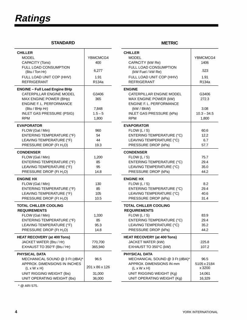
Ratings
CHILLERMODEL YBMCMCG4CAPACITY (Tons) 400FULL LOAD CONSUMPTION
(Btu / Ton Hr) 6,277
FULL LOAD UNIT COP (HHV) 1.91REFRIGERANT R134a
ENGINE – Full Load Engine BHpCATERPILLAR ENGINE MODEL G3406MAX ENGINE POWER (BHp) 365ENGINE F. L. PERFORMANCE
(Btu / BHp Hr) 7,848INLET GAS PRESSURE (PSIG) 1.5 – 5RPM 1,800
EVAPORATORFLOW (Gal / Min) 960ENTERING TEMPERATURE (°F) 54LEAVING TEMPERATURE (°F) 44PRESSURE DROP (Ft H2O) 19.3
CONDENSERFLOW (Gal / Min) 1,200ENTERING TEMPERATURE (°F) 85LEAVING TEMPERATURE (°F) 95PRESSURE DROP (Ft H2O) 14.8
ENGINE HXFLOW (Gal / Min) 130ENTERING TEMPERATURE (°F) 85LEAVING TEMPERATURE (°F) 105PRESSURE DROP (Ft H2O) 10.5
TOTAL CHILLER COOLING REQUIREMENTS
FLOW (Gal / Min) 1,330ENTERING TEMPERATURE (°F) 85LEAVING TEMPERATURE (°F) 95.3PRESSURE DROP (Ft H2O) 14.8
HEAT RECOVERY (at 400 Tons)JACKET WATER (Btu / Hr) 770,700EXHAUST TO 350°F (Btu / Hr) 365,940
PHYSICAL DATAMECHANICAL SOUND @ 3 Ft (dBA)* 96.5APPROX. DIMENSIONS IN INCHES
(L x W x H) 201 x 86 x 126
UNIT RIGGING WEIGHT (lbs) 31,000UNIT OPERATING WEIGHT (lbs) 36,000
* @ ARI 575.
STANDARD METRIC
CHILLERMODEL YBMCMCG4CAPACITY (kW Re) 1406FULL LOAD CONSUMPTION
(kW Fuel / kW Re) .523
FULL LOAD UNIT COP (HHV) 1.91REFRIGERANT R134a
ENGINECATERPILLAR ENGINE MODEL G3406MAX ENGINE POWER (kW) 272.3ENGINE F. L. PERFORMANCE
(kW / BkW) 3.08INLET GAS PRESSURE (kPa) 10.3 – 34.5RPM 1,800
EVAPORATORFLOW (L / S) 60.6ENTERING TEMPERATURE (°C) 12.2LEAVING TEMPERATURE (°C) 6.7PRESSURE DROP (kPa) 57.7
CONDENSERFLOW (L / S) 75.7ENTERING TEMPERATURE (°C) 29.4LEAVING TEMPERATURE (°C) 35.0PRESSURE DROP (kPa) 44.2
ENGINE HXFLOW (L / S) 8.2ENTERING TEMPERATURE (°C) 29.4LEAVING TEMPERATURE (°C) 40.6PRESSURE DROP (kPa) 31.4
TOTAL CHILLER COOLING REQUIREMENTS
FLOW (L / S) 83.9ENTERING TEMPERATURE (°C) 29.4LEAVING TEMPERATURE (°C) 35.2PRESSURE DROP (kPa) 44.2
HEAT RECOVERY (at 400 Tons)JACKET WATER (kW) 225.8EXHAUST TO 350°C (kW) 107.2
PHYSICAL DATAMECHANICAL SOUND @ 3 Ft (dBA)* 96.5APPROX. DIMENSIONS IN mm 5105 x 2184
(L x W x H) x 3200
UNIT RIGGING WEIGHT (Kg) 14,061UNIT OPERATING WEIGHT (Kg) 16,329

FORM 160.66-EG1
YORK INTERNATIONAL 5
COMPUTERIZED PERFORMANCE RATING
It is not practical to provide tabulated performance datafor every possible set of performance conditions sincethe energy requirements at both full and part-load varysignificantly. Computerized ratings are availablethrough each YORK sales office. These ratings can betailored to specific job requirements.
PART-LOAD PERFORMANCE
A chiller should be chosen not only to meet the full-loaddesign, but also for its ability to perform efficiently atlower loads and lower tower water temperatures. It isnot uncommon for chillers with the same full-load COPto have an operating cost difference of over 10% due topart-load operation.
Part-load information can be easily and accuratelygenerated by use of the computer. And because it is soimportant to an owner’s operating budget, this infor-mation has now been standardized in the form of anIntegrated Part-Load Value (IPLV), and ApplicationPart-Load Value (APLV).
IPLV or APLV is a single COP value that describespart-load performance of a chiller. It was originally
While IPLV/APLV provides a quick method of compar-ing part-load capabilities, this should not be construedas being “typical” for every, or even the majority ofjobs. The only valid information must take into accountactual building load profiles, and local weather data.Part-load performance data should be obtained foreach job using its own design criteria. “YorkCalc”,available at your local YORK sales representative, isan excellent tool for such evaluations.
IPLV or = .17A + .39B + .33C + .11DAPLV
WHERE: A = COP AT 100% CAPACITYB = COP AT 75% CAPACITYC = COP AT 50% CAPACITYD = COP AT 25% CAPACITY
devised to satisfy the needs of the new ANSI/ASHRAEStandard 90.1 (Standard For Energy Efficient Design ofNew Nonresidential And High-Rise Residential Build-ings). It is based on a schedule of “typical” operatinghours spent at each load point. This allows direct com-parison of each manufacturer’s part-load performanceon an equal basis. An example of the IPLV/APLVcalculation is shown below.
% ECWTTONS
POWER BTU/HP BTU/COP
WEIGHT WEIGHTEDCAP °F HP HR TRHR (LBS) COP
100 85.00 400 322 7,799 6,278 1.91 0.17 0.32494475 78.75 300 197 8,452 5,550 2.16 0.39 0.84324350 72.50 200 119 9,652 5,743 2.09 0.33 0.68953525 66.25 100 75 11,068 8,301 1.45 0.11 0.159017
% ECWTKWRE
POWER KWRE/ KWFUEL/COP
WEIGHT WEIGHTEDCAP °C BKW BKW KWRE (kPag) COP
100 29.40 1,406 240.1 3.06 0.523 1.91 0.17 0.32494475 26.00 1055 146.9 3.32 0.463 2.16 0.39 0.84324350 22.50 703.2 88.7 3.79 0.479 2.09 0.33 0.68953525 19.00 351.6 55.9 4.35 0.692 1.45 0.11 0.159017
STANDARD
METRIC
IPLV COP (HHV) 2.02
IPLV COP (HHV) 2.02
SAMPLE APLV CALCULATIONS

6 YORK INTERNATIONAL
MILLENNIUM Control Center
The Millennium YB Control Center, furnished as stan-dard on each Gas-Engine-Drive Chiller, provides theultimate in efficiency and chiller protection. State-of-the-art micro-electronics assure precise, reliable chill-er control logic and safety annunciations. The ControlCenter allows direct interfacing with the YORK Inte-grated Systems Network (ISN) building automationsystem, allowing complete integration of chiller,airside, and building automation controls. This featuremakes the YORK chiller the most versatile in themarket place.
INFORMATION DISPLAY
Vital chiller operating information can be shown on the40-character alphanumeric display. All information is inthe English language with numeric data provided inEnglish or metric units.
Information provided on all units as standard includes:
• Chilled liquid temperatures - entering and leaving • Condenser liquid temperatures - entering and leaving • Refrigerant pressures - evaporator and condenser • Differential oil pressure • % Engine load • Operating hours @ % load bins • Number of compressor starts • Saturation temperatures - evaporator and condenser • Discharge temperature • Compressor thrust bearing oil temperature • Engine RPM • Engine manifold pressure • Engine oil pressure • Engine jacket water temperature
In addition, all operating and setpoint information canbe transmitted to an optional remote printer through theRS-232 port to obtain data logs:
• At any time by pressing PRINT button • At set time intervals by programming the panel • Record of time and cause of safety and cycling
shutdowns with all operating information just prior toshutdown
• History printout of last four shutdowns
LEAVING CHILLED WATER TEMPERATURE CON-TROL
• Digital keypad entry of setpoint to 0.1°F (0.06°C). • Verify actual vs. setpoint temperature via alphanu-
meric display.
• Remote reset capability standard with YORK ISNBuilding Automation System, optional for otheranalog or discrete remote signals.
• Adjustable remote reset range (up to 20°F, 11.1°C)provides flexible, efficient use of remote signal de-pending on reset needs.
SYSTEM CYCLING CONTROLS
• Programmable seven-day time clock for automaticstart/stop of chiller, cooler and condenser waterpumps, and cooling tower.
• Separate schedule input strictly for holidays. • Remote cycling contacts available for other field-
supplied signals.
SYSTEM SHUTDOWN CONTROLS
The following safeties responsible for system shut-down are shown in English on the alphanumeric dis-play. Each annunciation details the day, time, reasonfor shutdown and type of restart required. All shut-downs are sequenced by the micro board except asnoted.
Cycling – those controls which automatically reset andpermit auto restart of the system
• Time clock • Low water temperature as sensed through the LWT
sensor. If a drop in water temperature occurs, theunit is stopped at 4°F (2.2°C) below the chilled liquid
27592A
FORM 160.66-EG1
YORK INTERNATIONAL 7
temperature setpoint. On a rise in water temperature,the unit restarts automatically.
• Remote/local cycling devices (field supplied).
• Multi-unit sequencing.
• Power fault relay.
• Low compressor oil temperature
• Aftercooler high inlet water temperature(Manual restart required)
• Undervoltage
• Vanes open
• Low differential compressor oil temperature
Safety – those controls which (when employed) requirea manual operation to depress the STOP-RESET switchand then COMPRESSOR START to restart the system.
• Chilled water pump interlock or flow switch. Flowmust be interrupted for a minimum of two secondsbefore shutdown will occur.
• High Compressor Discharge Temperature- fixed cutout provided by thermistor sensor.
• Compressor Thrust Bearing Position and OilTemperature- combination proximity probe and oil temperature
module shuts down compressor if either thresholdlimit is reached.
• High Compressor Oil Reservoir Temperature- fixed cutout provided by thermistor sensor.
Manual restart after Power Failure(jumper plug furnished if automatic restart isdesired).
• High or Low Compressor Oil Pressure- fixed cutout provided by differential between
separate transducer readings from the compressorsump and bearing feed line.
• Low Evaporator Pressure or High CondenserPressure- to avoid nuisance cycling, the compressor capacity
is held at cutout threshold for a safe period of time;if condition persists, a fixed cutout is provided bydedicated transducers.
• Remote stop (field-supplied signal).• Differential between Leaving Chilled Water and
Evaporator Saturation Temperatures- fixed cutout when value falls outside specified range
to detect faulty sensors. • Auxiliary shutdown • Faulty discharge temperature sensor • Engine overload • High engine water temperature • Low engine oil pressure • Evaporator transducer or probe error
• Clutch failure • Manual engine shutdown • Faulty compressor oil pressure transducer • Faulty proximity probe • Open thermocouple probe • Engine cranking, overspeed, fault • Engine panel shutdown • Engine PLC failure • Surge shutdown • Faulty condenser pressure transducer • Power failure (manual restart) • Compressor overspeed
CONTROL MODE SELECTION
There are three keys for the selection of the controlcenter modes:
• ACCESS CODE permits access to the MicroComputer PROGRAM and MODE buttons.
• PROGRAM permits the operator to program thesetpoints.
• MODE permits the operator to select the followingcontrol modes:
• LOCAL allows manual compressor start from thecompressor switch located on the control center.
• REMOTE allows remote start and stop of thecompressor and remote reset of the chilled watertemperature and load limit.
• SERVICE allows manual operation of the compres-sor prerotation vanes and engine speed through theOPEN, CLOSE, HOLD and AUTO keys. Manualoperation of the oil pump is also included.
FIELD INTERLOCKS – CHILLER STATUS
• Remote mode ready to start – contact closure indi-cates that the panel is in REMOTE mode and that theunit will start (all safeties and cycling devices satis-fied) when a remote start signal is received.
• Cycling shutdown – contact closure indicates that acycling shutdown has occurred and that the unit willrestart when the cycling control re-closes.
• Safety shutdown – contact closure indicates that asafety shutdown has occurred and that a manualreset is required to restart.
• Run contact – closure indicates that the panel isproviding a run signal to the engine.
• Remote engine load limit – PWM signal used to limitengine’s demand for natural gas.

8 YORK INTERNATIONAL
Mechanical Specifications
GENERAL
The YORK Millennium YB Gas-Engine-Drive Centri-fugal Chiller is completely factory packaged includingevaporator, condenser with integral subcooler, com-pressor, compressor lubrication system, natural gasengine, air actuated clutch, speed increaser, torsionalvibration reducing coupling, power panel, engine PLCpanel, Chiller Control Panel and all interconnecting unitpiping and wiring. The chiller is painted with durablealkyd-modified, vinyl enamel machinery paint prior toshipment.
The initial charge of compressor oil and refrigerant(HFC-134a) will be supplied, shipped in containers andcylinders for installation by YORK. The engine and thegearbox will be charged with the initial charge of oil priorto shipment. The engine jacket glycol and battery acidwill be supplied and installed by the local Caterpillardealer.
MOUNTING BASE
The engine, speed increaser, clutch, and compressorare mounted to a common driveline base. The drivelinebase is of heavy duty 12" (305 mm) I-beam construc-tion, specifically designed and built to resist deflection,maintain alignment, and to minimize linear vibration.
The driveline base is factory mounted on top of thechiller tubesheets. Four rubber isolators are installed(one at each corner of the driveline base) to isolate thedriveline from the chiller shells. Spring isolators,designed for 2" (50.8 mm) deflection, are installed ateach corner of the chiller shells to isolate the chillerfrom the workroom floor.
ENGINE
The industrial gas engine is manufactured by Cater-pillar Inc. The engine is a spark-ignited, turbocharged,6 cylinder stationary, liquid-cooled, four-cycle design,1800 RPM, stoichiometric inline configuration. Theengine is equipped with air filters, pressure gauges,lubricating oil cooler and filter, water pump and pres-sure gauge, service hour-meter, flywheel and flywheelhousing.
Structure and Metallurgy – The design of the basicengine provides for maximum structural integrity toextend service life. Materials used in the engine incor-porate the highest level of proven metallurgical andmanufacturing technology.
The block is a one-piece design, cast of high tensilestrength iron in the engine manufacturer’s own foundry.Cylinder wear surfaces are induction hardened overtheir entire length. Pistons are made of a lightweightaluminum alloy which is elliptically ground across theskirt and tapered from crown to skirt. Oil jets supplypiston cooling and lubricating oil. Valves are hard-facedwith replaceable inserts. The crankshaft is a one piecedesign. Connecting rods are made of high strength steelwith tapered pin bore.
Starting System – The engine has an electric startingsystem. The electric starting system includes 24 volt DCstarting motor, starter relay, and automatic reset circuitbreaker to protect against butt engagement. Batteriesare maintenance free, lead acid type mounted on acorrosion resistant rack near the starting motor. (Bat-tery acid supplied separately.) Also, a jacket waterheater will be included to maintain the jacket watertemperature to facilitate quick starts.
Engine Lubrication System – The lubrication oil pumpis a positive displacement type that is integral with theengine and gear driven from the engine gear train. Thesystem incorporates full flow filtration with bypass valveto continue lubrication in the event of filter clogging. Thebypass valve is integral with the engine filter base. Thepistons are oil cooled by continuous jet spray to theunderside, inside of the crown and piston ring.
Gaseous Fuel System – The gaseous fuel system isdesigned for gas pressure of 1.5 - 5 PSIG (10.3 - 34.5kPa), with an allowable fluctuation of .25 psi (1.7kPa).The gaseous fuel system consists of gas pres-sure regulators and carburetors. A balance line be-tween the regulator and engine inlet air manifold isprovided to compensate for air cleaner restriction andturbocharger boost. Carburetors are of the diaphragmtype with throttle body with a load screw for air-fuel ratioadjustment.
Ignition System – The unit is equipped with a magnetobased breakerless ignition system.
Governor – The engine governor is a WoodwardElectronic Speed Control with Flotech Electric Actua-tor. Speed is sensed by a magnetic pickup off theengine flywheel ring gear. A provision for remote speedadjustment is included to allow the chiller control panelto adjust engine speed based on load.
Cooling System – All waterside heat rejection from theengine is accomplished through factory piped connec-

FORM 160.66-EG1
YORK INTERNATIONAL 9
tions from the condenser water nozzles. The enginejacket glycol cooling system is a closed circuit designwith provision for filling, expansion, and de-aeration.The cooling pump is driven by the engine. The enginejacket coolant loop, aftercooler, and engine oil arecooled by the tower water through a plate and frameheat exchanger. Engine coolant temperature is inter-nally regulated to bypass the external cooling systemsuntil operating temperature is achieved.
Inlet Air System – The engine air cleaner is enginemounted with dry element. If external ducting is re-quired, care should be taken to minimize the restrictionassociated with the combustion air inlet. The maximumallowable restriction to the combustion air inlet is 27 inH2O (6.7 kPa).
Turbocharging – The turbocharger is of the axialturbine type driven by engine exhaust gases and direct-connected to the compressor supplying engine com-bustion air.
Aftercooling – An aftercooler is provided to lower theair/fuel mixture’s temperature after compression.Aftercooler core air surfaces are coated with a cor-rosion inhibitor to minimize oxidation.
SPEED INCREASER
The system is equipped with a factory aligned speedincreaser that will increase the rotating speed from thefull load engine RPM to optimized RPM required by thelow speed shaft of the compressor. The speed in-creaser is supplied with face hardened, single helicalgears and anti-friction bearings.
TORSIONAL COUPLING
A torsional coupling is selected to assure that ex-cessive torsional vibration levels are not transmitted tothe gearbox and compressor at all operating speeds.
CLUTCH
The units are equipped with a drive disconnect. Thedrum-type clutch is air actuated and specifically de-signed and manufactured for heavy equipment appli-cations. The clutch is an Airflex as manufactured byEaton Corp. The clutch allows the engine to warm upbefore engaging and loading the compressor. Theclutch also allows the engine to complete a cool downsequence, as recommended by Caterpillar, without the
compressor being engaged. It acts as a quick dis-connect in case of emergency shutdown and eliminatesengine backspin. Finally, it allows engine operation andtroubleshooting to be done without running the com-pressor, provided electricity and cooling water aresupplied.
COMPRESSOR
The compressor is a single-stage centrifugal type,driven by the natural gas engine. The housing is fullyaccessible with vertical circular joints. The completeoperating assembly is removable from the compressorand scroll housing. Compressor castings are designedfor a minimum working pressure of 200 PSIG (1379kPa g) and hydrostatic pressure tested at a minimum of300 PSIG (2068 kPa g). The rotor assembly consists ofa heat treated alloy steel drive shaft and impeller shaftwith a cast aluminum, fully shrouded impeller. Thecompressor shaft is laser aligned to the speed in-creaser at the YORK factory. The impeller is designedfor balanced thrust, and is dynamically balanced andoverspeed tested for smooth, vibration-free operation.Insert type journal bearings are fabricated of aluminumalloy, precision bored and axially grooved.
Internal single helical gears with crowned teeth aredesigned so that more than one tooth is in contact at alltimes to provide even distribution of the compressorload. Each gear is individually mounted in its ownjournal and thrust bearings to isolate it from impellerand drive forces.
The open drive compressor shaft seal consists of aspring loaded, precision carbon ring, high temperatureelastometer “O” ring static seal, and stress relieved,precision lapped collars. The seal features a small facearea and low rubbing speed. It provides an efficient sealunder high pressure conditions. The seal is oil flooded atall times and pressure-lubricated during compressoroperation.
COMPRESSOR LUBRICATION SYSTEM
Lubrication oil is force-fed to all bearings, gears, androtating surfaces by an oil pump which operates prior tostart-up and continuously during operation and duringcoastdown. A gravity-fed oil reservoir is built into the topof the compressor to provide lubrication during coast-down in the event of a power failure. An oil reservoir,separate from the compressor, contains a submersibleoil pump and two immersion-type oil heaters, thermo-statically controlled to remove refrigerant from the oil.

10 YORK INTERNATIONAL
Mechanical Specifications
Oil is filtered by an externally mounted replaceable car-tridge oil filter equipped with service valves, and cooledby a refrigerant cooled oil cooler before entering thecompressor. Oil piping on the driveline is completelyfactory installed and tested.
EVAPORATOR
The evaporator is of the flooded shell-and-tube type,designed for 180 PSIG (1241 kPa g) working pressureon the refrigerant side, and tested at 270 PSIG (1862kPa g). The shell is fabricated from rolled carbon steelplate with fusion welded seams; has carbon steel tubesheets, drilled to accommodate the tubes; and inter-mediate tube supports spaced no more than three feetapart (914 mm). The refrigerant side is designed,tested and stamped in accordance with ASME Boilerand Pressure Vessel Code, Section VIII-Division 1.
Tubes are high efficiency, externally and internallyenhanced type. Each tube is roller expanded into tubesheets providing a leak-proof seal. Tubes are 3/4" (19mm) O.D., 22 BWG, copper alloy and are individuallyreplaceable. Two liquid level sight glasses are locatedon the side of the shell to aid in determining properrefrigerant charge. The evaporator has two refrigerantrelief devices sized to meet the requirements ofASHRAE 15 Safety code for Mechanical Refrigeration.
Water boxes are removable to permit tube cleaning andreplacement. Stubout water box connections with 150 lbANSI raised face flanges are provided. Water boxesare designed for 150 PSIG (1034 kPa g) design workingpressure and tested at 225 PSIG (1551 kPa g). Plugged3/4" (19 mm) vent and drain connections are providedin each water box.
Factory-applied thermal insulation of the flexible,closed-cell plastic type, 3/4" (19 mm) thick is attachedwith vapor-proof cement to the cooler shell, flowchamber, tube sheets, suction connection, and (asnecessary) to the auxiliary tubing. Not included is theinsulation of compact water boxes and nozzles.
CONDENSER
The condenser is of the shell-and-tube type, designedfor 180 PSIG (1241 kPa g) working pressure on therefrigerant side, and tested at 270 PSIG (1861 kPa g).The shell is fabricated from rolled carbon steel platewith fusion welded seams; has carbon steel tubesheets, drilled to accommodate the tubes; and inter-
mediate tube supports spaced no more than four feetapart (1219 mm). An integral refrigerant subcooler isprovided for improved cycle efficiency. The refrigerantside is designed, tested and stamped in accordancewith ASME Boiler and Pressure Vessel Code, SectionVIII-Division 1. Tubes are high efficiency, externallyand internally enhanced type. Each tube is rollerexpanded into tube sheets providing a leak-proof seal.Tubes are 3/4" O.D. (19 mm), 22 BWG, copper alloyand are individually replaceable.
Water boxes are removable to permit tube cleaning andreplacement. Stubout water box connections with 150lb ANSI raised face flanges are provided. Water boxesare designed for 150 PSIG (1034 kPa g) design workingpressure and tested at 225 PSIG (1551 kPa g). Plugged3/4" (19 mm) vent and drain connections are providedin each water box. Condenser water boxes also includefactory supplied and piped connections for coolingwater to the plate frame heat exchanger to cool engineaftercooler and engine jacket glycol.
REFRIGERANT FLOW CONTROL
Refrigerant flow to the evaporator is controlled by asingle variable orifice. The variable orifice automati-cally adjusts to maintain proper refrigerant level in thecondenser and evaporator. This optimizes unit perfor-mance at varying load and temperature conditions andallows capacity above design at off-design conditions.
MICROCOMPUTER CONTROL CENTER
The unit is furnished complete with a MicroComputerControl Center in a locked enclosure. The chiller is con-trolled through a single panel. The panel has the capa-bility to control inlet guide vane position as well asengine speed in response to chiller load requirements.The control center includes a 40 character alphanu-meric display showing all system parameters in theEnglish language with numeric data in English or metricunits.
Digital programming of setpoints through a color coded,non-tactile keypad includes: leaving chilled liquid tem-perature, percent engine load limit, seven day timeclock for starting and stopping chiller and pumps,(complete with holiday schedule), remote reset tem-perature range, and data logger.
Security access is provided to prevent unauthorizedchange of setpoints, to allow local or remote control of

FORM 160.66-EG1
YORK INTERNATIONAL 11
the chiller, and to allow manual operation of theprerotation vanes and compressor oil pump.
All safety and cycle shutdowns are annunciated throughan alphanumeric display and consist of day, time, causeof shutdown, and type of restart required. Safety shut-downs include: low evaporator pressure, high con-denser pressure, auxiliary safety, high discharge tem-perature, faulty discharge temperature sensor, highcompressor oil temperature, power failure, engineoverload, loss of chilled water flow, high engine watertemperature, low engine oil pressure, low compressoroil pressure, high compressor oil pressure, evaporatortransducer or probe error, clutch failure, manual engineshutdown, faulty compressor oil pressure transducer,proximity sensor fault, high speed thrust bearing oildrain temperature, faulty proximity probe, open ther-mocouple probe, engine cranking, engine fault, engineoverspeed, compressor overspeed, engine PLC fault,engine panel shutdown, faulty condenser, and pressuretransducer. Cycling shutdowns will include: low com-pressor oil temperature, power failure (auto restart),low chilled water temperature, remote unit cycling,multi-unit cycling, internal time clock, vanes open,compressor low differential oil temperature, DC under-voltage, high aftercooler water temperature (manualrestart required), remote stop (field-supplied signal),remote/local cycling device, and multi-unit sequencing.
System operating information includes: return/leavingchilled liquid temperature, return/leaving condenserliquid temperatures; evaporator/condenser refrigerantpressures; differential compressor oil pressure, per-cent engine load, engine RPM, engine manifold pres-sure, evaporator/condenser saturation temperatures;compressor discharge temperature; compressor oiltemperature; operating hours; and number of startscounter, engine oil pressure, engine jacket temperatureand engine speed.
The chiller is provided with an RS-232 port to output allsystem operating data, shutdown/cycling messages,and a record of the last four cycling or safety shut-downs to a remote printer (field supplied). The controlcenter is programmable to provide data logs to theoptional printer at a preset time interval.
The Control Center is able to interface with a buildingautomation system to provide remote chiller start/stop;reset of chilled water temperature; remote engine loadlimit; and status messages indicating chiller is ready tostart, chiller is operating, chiller is shut down on a safe-ty requiring a manual reset, and chiller is shut down ona cycling safety.
The operating program is stored in nonvolatile memory(EPROM) to eliminate chiller failure due to AC powerfailure/battery discharge. In addition, programmed set-points are retained in lithium battery-backed TRCmemory for a minimum of 5 years.
VARIABLE SPEED CONTROL
Capacity control is achieved by use of prerotation vanesand varying engine speed. Capacity control logic ismatched to the specific chiller/compressor system.Control logic continually integrates the actual chilleroperating conditions, including chilled water tempera-ture and temperature setpoint, evaporator and conden-ser refrigerant pressures, engine speed and prerotationvane position. Prerotation vane position and enginespeed are automatically controlled by the panel tomaintain leaving chilled liquid temperature at thedesired setpoint. Engine speed is set to optimizesystem energy efficiency. The unit is capable of oper-ating at full and part load conditions with lower coolingtower water temperatures (down to 55°F / 12.8°C) atdesign condenser water flow rates. Prerotation vaneposition is automatically controlled by an externalelectric actuator.
POWER PANEL
The power panel enclosure houses the following com-ponents: single point wiring connection for incomingAC power supply; fused disconnect switch, compres-sor oil pump motor starter with overloads; heater relay;circuit breakers for 115VAC, 50/60 Hz, 3KVA controlsupply transformer.
NATURAL GAS ENGINE CONTROLS
Engine sensors include: engine oil pressure, jacketwater temperature, RPM, and inlet manifold pressure.As part of the engine control/safety system, the engineand related components are monitored and providedwith gauges or safety shutdowns to protect against anysystem failures. The safety shutoffs are low oil pres-sure, high water temperature, low jacket water level,and overspeed.
WATER STRAINERS
A water strainer of 1/16" (1.6 mm) mesh is factoryinstalled in the plate frame cooling water inlet. A waterstrainer of max 1/8" mesh must be installed in the towerwater circuit, as close to the condenser inlet as pos-

12 YORK INTERNATIONAL
sible. A water strainer of maximum 1/8" (3 mm) meshmay be installed in the chilled water inlet as close aspossible to the chiller if desired. Contact YORK Mar-keting for details.
ISOLATION MOUNTING
The entire unit is provided with industrial vibrationisolation mounts. These level adjusting, spring typeisolators are mounted on the tubesheets and aredesigned for two inch (50.8 mm) deflection.
TESTING
Prototype Testing – Specific prototype tests include:
ENGINE:
Performance (part load, full load)Oil ConsumptionFuel ConsumptionExhaust EmissionsNoise Levels (mechanical and exhaust)Startability (cold and hot ambients)Piston, Ring, and Liner Wear RatesPiston Structural IntegrityLubrication System EvaluationCooling System EvaluationValve Train Overspeed QualificationDeep Thermal Cycle EnduranceField Endurance
CHILLER ASSEMBLY:
Mechanical CompatibilityStructural IntegrityMounting EvaluationWiring CompatibilityControl Panel FunctionalityLinear Vibration MeasurementTorsional Vibration AnalysisLoad PerformanceSafety Shutdowns and AlarmsStart-Stop Evaluations
Production Testing – The refrigerant compressor isair run tested prior to mounting on the chiller. Theengine is run tested at full and part loads prior toassembly of the chiller. After assembly, the chillerpackage may be factory performance tested (if cus-tomer purchased) in YORK’s test facility. A certifiedreport of these tests is available if requested at the timeof a chiller order which includes the factory perfor-mance testing.
START-UP AND OPERATOR TRAINING
Factory-trained field service representatives willsupervise the final leak testing, charging and the initialstart-up, including driveline alignment. The completeinstallation will be checked for procedural and oper-ational compliance by a factory trained service repre-sentative from YORK. YORK will retain factory trainedservice representatives from Caterpillar to providestart-up service and operator instruction for the gasengine.
WARRANTY AND SERVICE
The standard warranty is for a period of one year fromthe date of start-up or eighteen months from shipment,whichever occurs first. The warranty includes parts andlabor during this period. This warranty does not includeparts an labor required for routine maintenance, suchas oil filters, air filters, oil, etc. This service is only to beperformed by YORK and Caterpillar factory trained andauthorized service personnel. YORK has a local directservice office that will provide factory trained service-men, the required stock of replacement parts, technicalassistance, and warranty administration. Engine main-tenance will only be performed by Caterpillar’s local,factory trained and authorized representative. YORKservice is the prime customer contact. Engine Mainte-nance / Warranty administration will only be performedthrough the local YORK service office by Caterpillar’slocal, factory trained and authorized representative.
Mechanical Specifications

FORM 160.66-EG1
YORK INTERNATIONAL 13
Accessories and Modifications
BAS REMOTE CONTROL
A communication interface permitting complete ex-change of chiller data with any BAS System is availablewith optional translator. Translator also allows BASSystem to issue commands to the chiller to control itsoperation. Translators come in two models, controllingup to 4 chillers and 8 chillers respectively.
OIL PRE-LUBE PUMP
This option provides a factory installed and testedcontinuous pre-lube oil pump. This pump will lubricateengine components prior to engine start.
WATER FLOW SWITCHES
These are paddle-type, vapor-proof water flow switch-es suitable for 150 PSIG (1034 kPa g) DWP for chilledand condenser water circuits. Switch for 115V-1-60service. A chilled water flow switch is required.Condenser water flow switch is optional.
SEQUENCE CONTROL KIT
For two, three or four units with chilled water circuitsconnected in series or parallel, the kit consists of returnwater thermostat, lead-lag selector switch for se-quence starting, and time delay relay, with NEMA-1enclosures, 115V-60 service.
AIR START SYSTEM
The air starting system will include air startingmotor(s), silencer, start valve, and pressure regulator.
The system shall have an operating pressure of 100PSIG. DC power will be supplied to the engine PLCpanel by a Regulated DC power supply mounted on theunit.
REMOTE RESET CONTROLS
Option board card file allows for continuous reset ofeither leaving chilled water temperature or percentengine load with Building Automation System. 4 to20mA, 0 to 10VDC, or discrete stepped signals can bewired directly to panel terminal block on the card filewithout any external interfacing.
VICTAULIC CONNECTIONS
Stub-out water nozzle connections with victaulicgrooves. Nozzles are suitable for either victaulic orwelded connections and are capped for shipment.
REFRIGERANT STORAGE / RECYCLING SYSTEM
A refrigerant storage/recycling system is a self-con-tained package consisting of a refrigerant compressorwith oil separator, storage receiver, water-cooled con-denser, filter drier and necessary valves and hoses toremove, replace and distill HFC-134a. All necessarycontrols and safety devices are a permanent part of thesystem.
OPTIONAL TUBES
Standard tubes for this unit will be 3/4" O.D., 22 BWG(.028" wall Cu). Optional tubes are available. (Contactfactory.)

14 YORK INTERNATIONAL
Application Data
LOCATION
The YB Gas-Engine-Drive chiller operating weightshould be considered when choosing the unit location.In selecting a site, consider structural support, accessfor service, and tube pull area. The unit site must be afloor, mounting pad or foundation which is level within1/4" (6.4 mm) and capable of supporting the operatingweight of the unit.
Sufficient clearance is required to permit normal ser-vice and maintenance work. A minimum of 36" (914mm) should be provided all around and above the unit.Additional space equal to the shell length should beprovided at one end of the unit to permit cleaning andremoval of cooler and condenser tubes as required. Adoorway or other properly located opening may beused.
The standard chiller should be installed in an indoorlocation where the temperature ranges from 50°F to110°F (10°C to 43.3°C).
VENTILATION
The ASHRAE Standard 15 Safety Code for MechanicalRefrigeration requires that all machinery rooms bevented to the outdoors utilizing mechanical ventilationby one or more power-driven fans. This standard, plusNational Fire Protection Association Standard 90A,state, local, and other codes should be checked forspecific requirements. These requirements should becompared to the requirements for engine ventilation toensure the equipment room is properly ventilated. (SeeForm 160.60-AD1)
An engine converts fuel into shaft horsepower and heat.This heat is removed through the jacket water system,aftercooler, exhaust gas system, and radiation fromengine surfaces. As a result, engine drives require dif-ferent installation considerations than electric motors.
Engine Driven Chiller equipment room considerationsshould include the following:
Fuel Supply – Natural gas fuel is a mixture of severalgases, each having different characteristics (heat value,specific gravity, etc.). The composition of natural gasvaries, but usually contains large amounts of methane, asmaller amount of ethane, and traces of other hydro-carbons. The amount of combustion air required willvary with the gas mixture provided by the local utility.The consumer must provide gas piping to the fuel inlet ofthe chiller driveline. (Gas pressure required per Table 1and Table 1A.) If other than pipeline natural gas is usedas the fuel source, contact your local YORK salesoffice for project specific requirements.
Engine Radiation – Three to six percent of the inputenergy (fuel) is typically lost as heat radiated to thesurrounding air. The removal of this radiated heatcauses an additional ventilation requirement that isadded to the combustion air. (Maximum radiation valueis provided in Table 1 and 1A.)
Exhaust Systems – The waste gases produced by theengine must be exhausted from the equipment room.See Form 160.60-AD1 for Exhaust Duct Details. Ex-haust systems must be designed and installed to dis-charge exhaust gases as quickly and silently as possiblewith a minimum amount of backpressure. Excessive
TABLE 1 – FULL LOAD ENGINE DATA
STANDARD
RPM 1800Max. BHP 365
Full Load Btu/Bhp Hr. (HHV) 7848Required Combustion Air (SCFM) 540Required Inlet Gas Pressure (psig) 1.5 - 5 + .25 max.
Max Exhaust Backpressure (IN. WC) 27Exhaust Flow (Lb/Hr) 2412Exhaust Temp (°F) 986
Radiated Heat (MBH) 115Recoverable Jacket (MBH) 856Recoverable Exhaust Heat (MBH) 430
NOX Emissions (gram/BHP Hr) 17.4
TABLE 1A – FULL LOAD ENGINE DATA
METRIC
RPM 1800
Max. kW 272.3Full Load Btu/Bhp Hr. (HHV) 3.08Required Combustion Air (L /S) 255
Required Inlet Gas Pres. (kPa g) 10.3-34.5 + 1.7 max.Max Exhaust Backpressure (KPa) 6.7Exhaust Flow (Kg / Hr) 1094
Exhaust Temp (°C) 530Radiated Heat (kW) 33.6Recoverable Jacket (kW) 251
Recoverable Exhaust Heat (kW) 126NOX Emissions (gram / kW) 23.3

FORM 160.66-EG1
YORK INTERNATIONAL 15
backpressure can cause horsepower losses andexhaust temperature increases. (Exhaust flow, tem-perature and maximum back pressure are provided inTable 1 and 1A.)
Heat Recovery – Heat is produced as a byproduct ofcombustion. 20% to 50% of the input energy to theengine must be removed by the cooling system. Engineheat is rejected into the oil cooler and engine jacketwater. The YORK driveline is provided with a unitmounted heat exchanger that has been sized and pre-plumbed and tested at the factory to reject the heat fromthese sources to the cooling tower. (Tower water flowand temperature are provided on page 4.) Heat can berecovered from the engine jacket water and the exhaustgas (minimum leaving exhaust temperature of 350°F /176.7°C). Heat recovery can significantly increase thethermal efficiency of the system.
Cranckcase Fumes – Normal combustion pressuresof the internal combustion engine cause a certainamount of blowby past the piston rings into the crank-case. To prevent pressure buildup in the crankcase,vent tubes are provided on the engine to allow the gasto escape. Crankcase gases must be discharged to theatmosphere and not into the equipment room. Aseparate ventilation system for the crankcase must beinstalled to connections provided on the engine toremove the blowby gases from the workroom.
Clutch Air Supply – A regulated clean air supplysufficient to provide 7SCFM @ 125 PSIG (3.3 L / S @861 kPa g) is required for pressurization of the airclutch. Instrument quality air is not required.
ENGINE STARTER
The YB chiller is provided with factory mounted electricengine starting systems. Electric starting is the mostconvenient, and adaptable for remote control andautomation. The electric starting system includes astarting motor, batteries, battery pack and charger.Each of these items is discussed in detail in Form160.60-AD1.
WATER CIRCUITS
Temperature Ranges – For normal water chilling duty,leaving chilled water temperatures may be selectedbetween 40°F and 50°F (4.4°C and 10°C) for watertemperature ranges between 3°F and 20°F (1.6°C and11.1°C). Contact YORK marketing for applicationsoutside this range.
Water Quality – The practical and economical appli-cation of liquid chillers requires that the quality of thewater supply for the condenser and cooler be analyzedby a water treatment specialist. Water quality mayaffect the performance of any chiller through corrosion,deposition of heat-resistant scale, sedimentation ororganic growth. These will hurt chiller performance andincrease operating and maintenance costs. Normally,performance may be maintained by corrective watertreatments and periodic cleaning of tubes. If waterconditions exist which cannot be corrected by properwater treatment, it may be necessary to provide alarger allowance for fouling, and/or to specify specialmaterials of construction.
General Piping – All chilled water and condenserwater piping should be designed and installed in ac-cordance with accepted piping practice. Chilled waterand condenser water pumps should be located todischarge through the chiller to assure positive pres-sure and flow through the unit. Piping should includeoffsets to provide flexibility and should be arranged toprevent drainage of water from the cooler and conden-ser when the pumps are shut down. Piping should beadequately supported and braced independent of thechiller to avoid the imposition of strain on chiller com-ponents. Hangers must allow for alignment of the pipe.Isolators in the piping and in the hangers are highlydesirable in achieving sound and vibration control.
Convenience Considerations – With a view to facili-tating the performance of routine maintenance work,some or all of the following steps may be taken by thepurchaser. Cooler and condenser water boxes areequipped with plugged vent and drain connections. If
TABLE 2 – WATER FLOW RATE LIMITS (GPM)
MINIMUM MAXIMUM
COOLER 1-Pass 1006 36262-Pass 503 18133-Pass 335 1209
CONDENSER 2-Pass 916 2834
TABLE 2A – WATER FLOW RATE LIMITS (L/S)
MINIMUM MAXIMUM
COOLER 1-Pass 63.5 228.82-Pass 31.7 114.43-Pass 21.1 76.3
CONDENSER 2-Pass 57.8 178.8

16 YORK INTERNATIONAL
Application Data
desired, vent and drain valves may be installed with orwithout piping to an open drain. Pressure gauges withstop cocks, and stop valves, may be installed in theinlets and outlets of the condenser and chilled waterline as close as possible to the chiller. An overheadmonorail or beam may be used to facilitate servicing.
Connections – The standard chiller is designed for150 PSIG working pressure in both the chilled waterand condenser water circuits. The connections (waternozzles) to these circuits are furnished with 150 # ANSIraised face flanges. Piping should be arranged for easeof disassembly at the unit for performance of suchroutine maintenance as tube cleaning. All water pipingshould be thoroughly cleaned of all dirt and debris beforefinal connections are made to the chiller. Connectionsinclude single point electrical power connection, gassupply connection, cooling water connection, exhaust,crankcase ventilation, clutch air supply, and air startsupply (if applicable), chilled water connection.
Chilled Water – The chilled water circuit should bedesigned for constant flow. A flow switch must beinstalled in the chilled water line of every circuit. Theswitch must be located in the horizontal piping close tothe unit, where the straight horizontal runs on each sideof the flow switch are at least five pipe diameters inlength. The switch must be electrically connected to thechilled water interlock position in the unit control center.A water strainer of maximum 1/8" (3 mm) mesh can befield-installed in the chilled water inlet line as close aspossible to the chiller. If located close enough to thechiller, the chilled water pump may be protected by thesame strainer. The flow switch and strainer assurechilled water flow during unit operation. The loss orsevere reduction of water flow could seriously impairthe chiller performance or even result in tube freeze-up.
Condenser Water – The condenser water circuitshould be designed for constant flow. A flow switchshould be installed in the condenser water line of everycircuit. The switch must be located in the horizontal pipingclose to the unit, where the straight horizontal runs oneach side of the flow switch are at least five pipediameters in length. The switch must be elec-tricallyconnected to the condenser water interlock position in theunit control center. A water strainer of maximum 1/8"(3 mm) mesh must be field-installed in the condenserwater inlet line as close as possible to the chiller. Iflocated close enough to the chiller, the condenser waterpump may be protected by the same strainer. The flowswitch and strainer assure con-denser water flow duringunit operation. The loss or severe reduction of water flow
could seriously impair the chiller performance or evenresult in tube freeze-up.
The chiller is engineered for maximum efficiency at bothdesign and part load operation by taking advantage ofthe colder cooling tower water temperatures whichnaturally occur during the winter months. Appreciablepower savings are realized from these reduced heads.Exacting control of condenser water temperature, re-quiring an expensive cooling tower bypass, is notnecessary for most applications.
For the usual full load design of 10°F (5.5°C) condenserwater temperature range, the chiller only requires thatthe minimum entering condenser water temperature beat least 7°F (3.9°C) higher than the leaving chilled watertemperature.
The minimum entering condenser water temperature forother full and part load conditions is provided by thefollowing equation:
Min. ECWT = LCHWT – C RANGE + 17
Where:
ECWT = entering condensing water temperature
LCHWT = leaving chilled water temperature
C RANGE = condensing water temperature range
At initial startup, entering condensing water temperaturemay be as much as 25°F (13.9°C) colder than thestandby chilled water temperature. Cooling tower fancycling will normally provide adequate control ofentering condenser water temperature on most instal-lations, to keep above the minimum temperature.Cycling for any other reason will cost significantly moreHP than what is saved on the tower fans and pumps.
Additional tower water is required for engine cooling.This is factory piped to the condenser cooling waterconnections. Maximum water temperature allowable tothe heat exchanger is 85°F (29.4°C). Water flows andtemperatures for the engine are provided in Table 1 and1A.
MULTIPLE UNITS
Many applications require multiple units to meet the totalcapacity requirements as well as to provide flexibilityand some degree of protection against equipment shut-down. There are several common unit arrangements forthis type of application. The Millennium chiller has been

FORM 160.66-EG1
YORK INTERNATIONAL 17
FIG. 1 – PARALLEL COOLERSPARALLEL CONDENSERS
FIG. 2 – SERIES COOLERSPARALLEL CONDENSERS
LD00507
LD00508
COND. 1
COND. 2
COOLER1
COOLER2
COND. 1 COND. 2
COOLER1
COOLER2
S1 S2
S
T
– Temperature Sensor For Chiller Capacity Control
– Thermostat For Chiller Capacity Control
designed to be readily adapted to the requirements ofthese various arrangements.
Parallel Arrangement (Refer to Fig. 1) – Chillers maybe applied in multiples with chilled and condenser watercircuits connected in parallel between the units.Assuming two units of equal size, each will reduce incapacity as the load decreases to about 40% of the totalcapacity, at which point one of the units will be shut downby a sequence control.
Assuming chilled water flow to the inoperative unit isstopped by pump shutdown and/or a closed valve, theremaining unit will pick up the total remaining load andcontinue to reduce in capacity as the load decreases.The unit will cycle off on the low chilled water tem-perature control when the load reduces below minimumunit capacity. The controls can maintain constant (+/–.5°F / .28°C) leaving chilled water temperature at allloads.
If chilled water continues to flow through the non-operating unit, the chilled water flowing through theoperating unit will mix with the water leaving the non-operating unit to produce a common water supply to theload. Since control of the operating unit is from its ownleaving chilled water temperature, the common tem-perature to the load will rise above the full load designtemperature. This higher chilled water temperatureoccurs below 40% load when the dehumidification loadin normal air conditioning applications is usually quitelow. In such instances, this temperature rise will saveadditional energy.
The running time may be apportioned between both unitsby alternating the shutoff sequence.
Series Arrangement (Refer to Fig. 2) – Chillers maybe applied in multiples with chilled water circuits con-nected in series and condenser water circuits con-nected in parallel. All of the chilled water flows throughboth coolers with each unit handling approximatelyone-half of the total load. When the load decreases toabout 40% of the total capacity, one of the units will beshut down by sequence control. Since all water isflowing through the operating unit, that unit will cool thewater to the desired temperature.
REFRIGERANT RELIEF PIPING
Each chiller is equipped with a dual pressure-reliefvalve. The purpose of the relief valve is to quickly relieveexcess pressure of the refrigerant charge to theatmosphere, as a safety precaution in the event of anemergency such as fire. They are set to relieve at aninternal pressure of 180 psig, are located on the coolerand are provided in accordance with the ASHRAE 15Safety Code and ASME Code for Unfired Pressurevessels.
Sized to the requirements of applicable codes, a ventline must run from the relief device to the outside of thebuilding. This refrigerant relief piping must include acleanable, vertical-leg dirt trap to catch vent-stackcondensation. Vent piping must be arranged to avoidimposing a strain on the relief connection and shouldinclude one flexible connection.

18 YORK INTERNATIONAL
VIBRATION AND SOUND CONSIDERATIONS
A Gas-Engine-Drive Millennium chiller is not a sourceof objectionable vibration in normal air conditioningapplications. The unit is furnished with vibration isolationin the form of spring isolators on the chiller tubesheets.
Control of sound and vibration transmission must betaken into account in the equipment room constructionas well as in the selection and installation of theequipment. Sound attenuation may be required forequipment room, exhaust gas systems, or mechanicalnoise. The design of the equipment room shouldaddress these sources of noise. (Additional informationis provided in Form 160.60-AD1)
Millennium chiller sound pressure level ratings per ARI575 will be furnished on request.
THERMAL INSULATION
No appreciable operating economy can be achieved bythermally insulating the chiller. However, the chiller’scold surfaces should be insulated with a vapor barrierinsulation sufficient to prevent condensation. Insulationrequirements are provided in Table 3.
AC POWER PANEL LUG SIZE RANGE #14 - #4
JACKET WATER HEATER KW 6
MINIMUM CIRCUIT AMPACITY 17.1
MINIMUM FUSE SIZE 25
MAXIMUM FUSE SIZE 30
NOTE: All values are for 460V – 3-Phase – 60 Hz electrical service.
Application Data
ELECTRICAL DATA
Table 4 contains unit electrical data.
TABLE 4 – ELECTRICAL REQUIREMENTS
TABLE 3 – COOLER INSULATION REQUIREMENTS
Muffler and exhaust pipe insulation is recommended tominimize radiation from these sources to the chillerroom. This will minimize ventilation requirements. Thisis not covered by the scope of supply of York Inter-national.
WATERBOX (SQ. FT.) (SQ. M)
STANDARD 280 26

FORM 160.66-EG1
YORK INTERNATIONAL 19
Dimensions (Ft. - Ins.)
NO
TE
: 2-P
ass
Coo
ler a
nd C
onde
nser
sho
wn.
For
oth
er P
ass
arra
ngem
ents
, see
Pag
e 21
.
LD
02
14
1ft

20 YORK INTERNATIONAL
Dimensions (mm)
NO
TE
: 2-P
ass
Coo
ler a
nd C
onde
nser
sho
wn.
For
oth
er P
ass
arra
ngem
ents
, see
Pag
e 21
.
LD
02
14
1m
m

FORM 160.66-EG1
YORK INTERNATIONAL 21
Dimensions - Nozzle Arrangements (Compact Water Boxes)
NOTES:
1. All dimensions are approximate. Certified dimensions are available upon request.
2. Standard water nozzles are furnished with 150 lb. (1034 kPa g) ANSI raised face flanges. Companion flanges,nuts, bolts and gaskets are not furnished. Victaulic groove connections, suitable for victaulic or weldedconnections, are available.
3. Nozzle arrangements are available only as shown. Any pair of cooler nozzles used in combination with any pairof condenser nozzles.
4. Condenser water must enter the water box through the bottom connection for proper operation of the sub-coolerto achieve rated performance.
5. Connected piping should allow for removal of compact water box for tube access and cleaning.
WATER BOX DIMENSIONS
COMP. SHELL COOLER CONDENSER
CODE CODE AA EE FF BB DD GG
G4 M1'–10" 0'–8-1/2" 1'–9-1/2" 2'–2-3/4" 3'–9-3/4" 1'–5-1/2"
559 mm 216 mm 546 mm 679 mm 1162 mm 445 mm
NOZZLE ARRANGEMENTS
NO. OF COOLER CONDENSERPASSES IN OUT IN OUT
1A D — —D A — —B C J H
2C B M LE F — —F E — —
3A D — —D A — —
ENGINE ENDLD00965(R)
COMPRESSOR END
NOZZLE SIZES
SHELLCOOLER CONDENSER
CODE NO. OF PASSES NO. OF PASSES
1 2 3 2
M10" 8" 6" 10"
254 mm 203 mm 152 mm 254 mm

22 YORK INTERNATIONAL
Guide Specifications
Furnish and install where indicated on the drawings_____ YORK factory-packaged gas engine driven cen-trifugal liquid chilling unit(s). Each unit shall produce acapacity of _____ tons cooling ______ GPM of waterfrom _____ °F to _____ °F when the condenser issupplied with ______ GPM of tower water at 85°F. Shaftpower requirements shall be ______ HP. Unit HHVCOP shall be ______ at full load. The cooler shall beselected for .00025 Hr-Ft2-°F/Btu fouling factor with amaximum chilled water pressure drop of ______ feetH2O. Evaporator water side shall be designed for 150PSIG working pressure. Total tower water requiredshall not exceed ____ GPM with a water pressure dropof ____ feet H2O. The total tower water required shallbe distributed by factory assembled and flow balancedpiping to supply ____ GPM of water to the condenserand 130 GPM to the engine cooling heat exchanger at85°F. The tower water circuit shall be selected for.00025 Hr-Ft2-°F/Btu fouling factor. The tower waterside shall be designed for 150 PSIG working pressure.Power shall be supplied to the unit at 460 volts – 3-phase – 60 hertz.
– or –
Furnish and install where indicated on the drawings_____ YORK factory-packaged gas engine driven cen-trifugal liquid chilling unit(s). Each unit shall produce acapacity of _____ kW cooling ______ L/s of water from_____ °C to _____ °C when the condenser is suppliedwith _____ L/s of tower water at _____ °C. Shaft powerrequirements shall be ______ kW. Unit HHV COP shallbe______ at full load. The cooler shall be selected for.000044 m2C/W fouling factor with a maximum chilledwater pressure drop of ______ kPa. Evaporator waterside shall be designed for 10.3 bar g working pressure.Total tower water required shall not exceed ____ L/swith a water pressure drop of ____ kPa. The total towerwater required shall be distributed by factory assem-bled and flow balanced piping to supply ____ L/s ofwater to the condenser and 8.2 L/s to the engine cool-ing heat exchanger at 29.4°C. The tower water circuitshall be selected for .000044 m2C/W fouling factor. Thetower water side shall be designed for 10.3 bar g work-ing pressure. Power shall be supplied to the unit at ____volts – 3-phase – 50 hertz.
GENERAL
The gas engine driven centrifugal chiller shall be acompletely factory packaged unit including evaporator,condenser with integral subcooler, compressor, com-
pressor lubrication system, natural gas engine, airactuated clutch, speed increaser, torsional vibrationreducing coupling, power panel, engine PLC panel,chiller control panel and all interconnecting unit pipingand wiring. The chiller shall be painted with durablealkyd-modified, vinyl enamel machinery paint prior toshipment.
The initial charge of compressor oil and refrigerant(HFC-134a) will be supplied, shipped in containers andcylinders for field installation by YORK. The engine andthe gearbox will be charged with the initial charge of oilprior to shipment. The engine jacket glycol and batteryacid will be supplied and installed by the local enginemanufacturer’s representative.
MOUNTING BASE
The engine, speed increaser, clutch, and compressorshall be mounted to a common driveline base. Thedriveline base shall be of heavy duty 12" (305 mm)I-beam construction, specifically designed and built toresist deflection, maintain alignment, and to minimizelinear vibration.
The driveline base shall be factory mounted on top ofthe chiller tubesheets. Four rubber isolators shall be in-stalled (one at each corner of the driveline base) to isolatethe driveline from the chiller shells. Spring isolators,designed for 2 inch (51 mm) deflection, shall be installedat each corner of the chiller shells to isolate the chillerfrom the workroom floor.
ENGINE
The industrial gas engine shall be manufactured byCaterpillar Inc. The engine shall be a spark-ignited,turbocharged, 6-cylinder, stationary, liquid-cooled,four-cycle design, 1800 RPM, stoichometric inline con-figuration. The engine shall be equipped with air filters,pressure gauges, lubricating oil cooler and filter, waterpump and pressure gauge, service hour-meter, flywheeland flywheel housing.
Structure and Metallurgy – The design of the basicengine shall provide for maximum structural integrity toextend service life. Materials used in the engine shallincorporate the highest level of proven metallurgicaland manufacturing technology.
The block shall be a one-piece design and cast of hightensile strength iron in the engine manufacturer’s own

FORM 160.66-EG1
YORK INTERNATIONAL 23
foundry. Cylinder wear surfaces shall be inductionhardened over their entire length. Pistons shall be madeof a lightweight aluminum alloy which shall be ellip-tically ground across the skirt and tapered from crownto skirt. Oil jets supply piston cooling and lubricating oil.Valves shall be hard-faced with replaceable inserts.The crankshaft shall be a one-piece design. Con-necting rods shall be made of high strength steel withtapered pin bore.
Starting System – The engine shall have an electricstarting system. The electric starting system includes24 volt DC starting motor, starter relay, and automaticreset circuit breaker to protect against butt engage-ment. Batteries shall be maintenance free, lead acidtype mounted on a corrosion resistant rack near thestarting motor. Also, a jacket water heater will beincluded to maintain the jacket water temperature tofacilitate quick starts.
Engine Lubrication System – The lubrication oil pumpshall be a positive displacement type that shall beintegral with the engine and gear driven from the enginegear train. The system shall incorporate full flow filtra-tion with bypass valve to continue lubrication in theevent of filter clogging. The bypass valve shall beintegral with the engine filter base. The pistons shall beoil cooled by continuous jet spray to the underside,inside of the crown and piston ring.
Gaseous Fuel System – The gaseous fuel systemshall consist of gas pressure regulators and car-buretors. A balance line between the regulator andengine inlet air manifold shall be provided to compen-sate for air cleaner restriction and turbocharger boost.Carburetors shall be of the diaphragm type with throttlebody with a load screw for air-fuel ratio adjustment. Theengine shall operate with a gas supply from 1.5 to 5PSIG (10.3 to 34.5 kPa g), with a maximum fluctuationno greater than ± 0.25 psi (1.7 kPa).
Ignition System – The unit shall be equipped with amagneto based breakerless ignition system.
Governor – The engine governor shall be a WoodwardElectronic Speed Control with Flotech Electric Actua-tor. Speed shall be sensed by a magnetic pickup off theengine flywheel ring gear. A provision for remote speedadjustment shall be included to allow the chiller controlpanel to adjust engine speed based on load.
Cooling System – All waterside heat rejection from theengine shall be accomplished through factory piped
connections from the condenser water nozzles. Theengine jacket glycol cooling system shall be a closedcircuit design with provision for filling, expansion, anddeaeration. The cooling pump shall be driven by theengine. The engine jacket coolant loop, aftercooler, andengine oil, shall be cooled by the tower water through aplate and frame heat exchanger. Engine coolant tem-perature shall be internally regulated to bypass theexternal cooling systems until operating temperature isachieved.
Inlet Air System – The engine air cleaner shall beengine mounted with dry element. If external ducting isrequired, care should be taken to minimize the restric-tion associated with the combustion air inlet. Themaximum restriction to the combustion air inlet shall be27 inches H
2O (6.7 kPa).
Turbocharging – The turbocharger shall be of the axialturbine type driven by engine exhaust gases and direct– connected to the compressor supplying engine com-bustion air.
Aftercooling – An aftercooler shall be provided tolower the air\fuel mixture’s temperature after com-pression. Aftercooler core air surfaces shall be coatedwith a corrosion inhibitor to minimize oxidation.
SPEED INCREASER
The system shall be equipped with a factory alignedspeed increaser that will increase the rotating speedfrom the full load engine RPM to optimized RPMrequired by the low speed shaft of the compressor. Thespeed increaser shall be supplied with face hardened,single helical gears and anti-friction bearings.
TORSIONAL COUPLING
A torsional coupling shall be selected to assure thatexcessive torsional vibration levels are not transmittedto the gearbox and compressor at all operating speeds.
CLUTCH
The units shall be equipped with a drive disconnect. Thedrum-type clutch shall be air actuated and specificallydesigned and manufactured for heavy equipmentapplications. The clutch shall be an Airflex as manu-factured by Eaton Corp. The clutch allows the engine towarm up before engaging and loading the compressor.

24 YORK INTERNATIONAL
Guide Specifications
The clutch also allows the engine to complete a cooldown sequence, as recommended by the engine man-ufacturer, without the compressor being engaged.
The clutch also eliminates engine backspin uponshutdown of the chiller. Additionally, the clutch allowsfor quick disconnect in the event of emergency shut-down and for engine operation/troubleshooting withoutengaging and loading the compressor (provided elec-tric power and cooling water are supplied).
COMPRESSOR
The compressor shall be a single stage centrifugaltype, driven by the natural gas engine. The housingshall be fully accessible with vertical circular joints.The complete operating assembly shall be removablefrom the compressor and scroll housing. Compressorcastings shall be designed for a minimum workingpressure of 200 PSIG (1379 kPa g) and hydrostaticpressure tested at a minimum of 300 PSIG (2068kPa g). The rotor assembly consists of a heat treatedalloy steel drive shaft and impeller shaft with a castaluminum, fully shrouded impeller. The compressorshaft shall be laser aligned to the speed increaser at thechiller manufacturer’s factory. The impeller shall bedesigned for balanced thrust, and shall be dynamicallybalanced and overspeed tested for smooth, vibrationfree operation. Insert type journal bearings shall befabricated of aluminum alloy, precision bored andaxially grooved.
Internal single helical gears with crowned teeth shall bedesigned so that more than one tooth is in contact at alltimes to provide even distribution of the compressorload. Each gear shall be individually mounted in its ownjournal and thrust bearings to isolate it from impellerand drive forces.
The open drive compressor shaft seal consists of aspring loaded, precision carbon ring, high temperatureelastometer “O” ring static seal, and stress relieved,precision lapped collars. The seal features a small facearea and low rubbing speed. It provides an efficient sealunder high pressure conditions. The seal shall be oilflooded at all times and pressure-lubricated duringcompressor operation.
COMPRESSOR LUBRICATION SYSTEM
Lubrication oil shall be force-fed to all bearings, gears,
and rotating surfaces by an oil pump which operatesprior to start-up and continuously during operation andduring coastdown. A gravity-fed oil reservoir shall bebuilt into the top of the compressor to provide lubri-cation during coastdown in the event of a power failure.An oil reservoir, separate from the compressor, con-tains a submersible oil pump and two immersion-typeoil heaters, thermostatically controlled to remove re-frigerant from the oil. Oil shall be filtered by anexternally mounted replaceable cartridge oil filterequipped with service valves, and cooled by a re-frigerant cooled oil cooler before entering the com-pressor. Oil piping on the driveline shall be completelyfactory installed and tested.
EVAPORATOR
The evaporator shall be of the flooded shell-and-tubetype, designed for 180 PSIG (1862 kPa g) workingpressure on the refrigerant side, and tested at 270PSIG (1241 kPa g). The shell shall be fabricated fromrolled carbon steel plate with fusion welded seams;shall have carbon steel tube sheets, drilled to accom-modate the tubes; and intermediate tube supportsspaced no more than three feet apart (914 mm). Therefrigerant side shall be designed, tested and stampedin accordance with ASME Boiler and Pressure VesselCode, Section VIII-Division 1.
Tubes shall be high efficiency, externally and internallyenhanced type. Each tube shall be roller expanded intotube sheets providing a leak-proof seal. Tubes shall be3/4" O.D. (19 mm), 22 BWG, copper alloy and shall beindividually replaceable. Two liquid level sight glassesshall be located on the side of the shell to aid indetermining proper refrigerant charge. The evaporatorshall have two refrigerant relief devices sized to meetthe requirements of ASHRAE 15 Safety code forMechanical Refrigeration.
Water boxes shall be removable to permit tube cleaningand replacement. Stubout water box connections with150 lb (1034 kPa) ANSI raised face flanges shall beprovided. Water boxes shall be designed for 150 PSIG(1034 kPa g) design working pressure and be tested at225 PSIG (1551 kPa g). Plugged 3/4" (19 mm) vent anddrain connections shall be provided in each water box.Factory-applied thermal insulation of the flexible,closed-cell plastic type, 3/4" (19 mm) thick shall beattached with vapor-proof cement to the cooler shell,flow chamber, tube sheets, suction connection, and (asnecessary) to the auxiliary tubing.

FORM 160.66-EG1
YORK INTERNATIONAL 25
CONDENSER
The condenser shall be of the shell-and-tube type,designed for 180 PSIG (1241 kP g) working pressureon the refrigerant side, and tested at 270 PSIG (1862kPa g). The shell shall be fabricated from rolled carbonsteel plate with fusion welded seams; shall have carbonsteel tube sheets, drilled to accommodate the tubes;and intermediate tube supports spaced no more thanfour feet apart (1219 mm). An integral refrigerant sub-cooler shall be provided for improved cycle efficiency.The refrigerant side shall be designed, tested andstamped in accordance with ASME Boiler and PressureVessel Code, Section VIII-Division 1. Tubes shall behigh efficiency, externally and internally enhancedtype. Each tube shall be roller expanded into tubesheets providing a leakproof seal. Tubes shall be 3/4"O.D. (19 mm), 22 BWG, copper alloy and shall beindividually replaceable.
Water boxes shall be removable to permit tube cleaningand replacement. Stubout water box connections with150 lb (1034 kPa) ANSI raised face flanges shall beprovided. Water boxes shall be designed for 150 PSIG(1034 kPa g) design working pressure and be tested at225 PSIG (1551 kPa g). Plugged 3/4" (19 mm) vent anddrain connections shall be provided in each water box.Condenser water boxes also include factory suppliedand piped connections for cooling water supply to theengine plate frame heat exchanger.
REFRIGERANT FLOW CONTROL
Refrigerant flow to the evaporator shall be controlled bya single variable orifice.The variable orifice shall auto-matically adjust to maintain proper refrigerant level inthe condenser and evaporator. This shall optimize unitperformance at varying load and temperature condi-tions and allow capacity above design at off-designconditions.
CHILLER MICROCOMPUTER CONTROL CENTER
The unit shall be furnished complete with a Micro-Computer Control Center in a locked enclosure. Thechiller shall be controlled through a single panel. Thepanel shall have the capability to control inlet guidevane position as well as engine speed in response tochiller load requirements. The Control Center shallinclude a 40 character alphanumeric display showingall system parameters in the English language withnumeric data in English or metric units.
Digital programming of setpoints through a color coded,non-tactile keypad shall include: leaving chilled liquidtemperature, percent engine load limit, seven day timeclock for starting and stopping chiller and pumps,(complete with holiday schedule), remote resettemperature range, and data logger.
Security access shall be provided to prevent unauth-orized change of setpoints, to allow local or remotecontrol of the chiller, and to allow manual operation of theprerotation vanes and compressor oil pump.
All safety and cycle shutdowns shall be annunciatedthrough an alpha numeric display and consist of day,time, cause of shutdown, and type of restart required.Safety shutdowns shall include: low evaporator pres-sure, high condenser pressure, auxiliary safety, highdischarge temperature, faulty discharge temperaturesensor, high compressor oil temperature, power fail-ure, engine overload, loss of chilled water flow, highengine water temperature, low engine oil pressure, lowcompressor oil pressure, high compressor oil pres-sure, evaporator transducer or probe error, clutchfailure, manual engine shutdown, faulty compressor oilpressure transducer, proximity sensor fault, highspeed thrust bearing oil drain temperature, faultyproximity probe, open thermocouple probe, enginecranking, engine fault, engine overspeed, compressoroverspeed, engine PLC fault, engine panel shutdown,faulty condenser, and pressure transducer. Cyclingshutdowns will include: low compressor oil tempera-ture, power failure (auto restart), low chilled watertemperature, remote unit cycling, multi unit cycling,internal time clock, vanes open, compressor lowdifferential oil temperature, DC under-voltage, highaftercooler water temperature (manual restart re-quired), remote stop (field-supplied signal), remote/local cycling device, and multi-unit sequencing.
System operating information shall include: return/leaving chilled liquid temperature, return/leaving con-denser liquid temperatures; evaporator/condenserrefrigerant pressures; differential compressor oil pres-sure, percent engine load, engine RPM, enginemanifold pressure, evaporator/condenser saturationtemperatures; compressor discharge temperature;compressor oil temperature; operating hours; andnumber of starts counter, engine oil pressure, enginejacket temperature and engine speed.
The chiller shall be provided with an RS-232 port tooutput all system operating data, shutdown/cycling

26 YORK INTERNATIONAL
Guide Specifications
messages, and a record of the last four cycling orsafety shutdowns to a remote printer (field supplied).The control center shall be programmable to providedata logs to the optional printer at a preset time interval.
The Control Center shall be able to interface with abuilding automation system to provide remote chillerstart/stop; reset of chilled water temperature; remoteengine load limit; and status messages indicating chilleris ready to start, chiller is operating, chiller is shut downon a safety requiring a manual reset, and chiller is shutdown on a cycling safety.
The operating program shall be stored in nonvolatilememory (EPROM) to eliminate chiller failure due to ACpower failure\battery discharge. In addition, pro-grammed setpoints shall be retained in lithium battery-backed TRC memory for a minimum of 5 years.
VARIABLE SPEED CONTROL
Capacity control shall be achieved by use of prerotationvanes and varying engine speed. Capacity control logicshall be matched to the specific chiller/compressorsystem. Control logic shall continually integrate theactual chiller operating conditions, including chilledwater temperature and temperature set point, evapo-rator and condenser refrigerant pressures, enginespeed and prerotation vane position. Prerotation vaneposition and engine speed shall be automaticallycontrolled by the chiller control panel to maintainleaving chilled liquid temperature at the desired set-point. Engine speed shall be set to optimize systemenergy efficiency. During part load operation, the chillershall be able to operate with cooling tower water as lowas 55°F (12.8°C) at design condenser water flow rates.Pre-rotation vane position shall be automatically con-trolled by an external electric actuator.
POWER PANEL
The power panel enclosure shall house the followingcomponents: single point wiring connection forincoming AC power supply; fused disconnect switch,compressor oil pump motor starter with overloads;heater relay; circuit breakers for 115VAC, 60 Hz, 3KVAcontrol supply transformer. The chiller shall be avail-able in 460V – 3-phase – 60 Hz.
NATURAL GAS ENGINE CONTROLS
Engine sensors shall include: engine oil pressure,jacket water temperature, RPM, and inlet manifoldpressure. As part of the engine control/safety systemthe engine and related components shall be monitoredand provided with gauges or safety shutdowns toprotect against any system failures. The safety shut-offs shall be low oil pressure, high water temperature,low jacket water level, and overspeed.
ISOLATION MOUNTING
The entire unit shall be provided with industrial vibrationisolation mounts. These level adjusting, spring typeisolators shall be mounted on the tubesheets and shallbe designed for two inch (51 mm) deflection.
TESTING
Prototype Testing –
Specific prototype tests shall include:
ENGINE:Performance (part load, full load)Oil ConsumptionFuel ConsumptionExhaust EmissionsNoise Levels (mechanical and exhaust)Startability (cold and hot ambients)Piston, Ring, and Liner Wear RatesPiston Structural IntegrityLubrication System EvaluationCooling System EvaluationValve Train Overspeed QualificationDeep Thermal Cycle EnduranceField Endurance
CHILLER ASSEMBLY:
Mechanical CompatibilityStructural IntegrityMounting EvaluationWiring Compatibility

FORM 160.66-EG1
YORK INTERNATIONAL 27
Control Panel FunctionalityLinear Vibration MeasurementTorsional Vibration AnalysisLoad PerformanceSafety Shutdowns and AlarmsStart-Stop Evaluations
Production Testing – The refrigerant compressorshall be air run tested prior to mounting on the chiller.The engine shall be run tested at full and part loads priorto assembly of the chiller. After assembly, the chillerpackage may be factory performance tested (if pur-chased) in the manufacturer’s factory test facility. Acertified test report will be available if requested at thetime the unit is purchased with the factory performancetesting.
START-UP AND OPERATOR TRAINING
Factory trained field service representatives shallsupervise the final leak testing, charging and the initialstart-up. The complete installation shall be checked forprocedural and operational compliance by a factorytrained service representative from the chiller man-ufacturer. The chiller manufacturer shall retain factory
trained service representatives from Caterpillar toprovide start up service and operator instruction for thegas engine.
WARRANTY AND SERVICE
The standard warranty shall be for a period of one yearfrom the date of start-up or eighteen months fromshipment, whichever occurs first. The warranty includesparts and labor during this period. This warranty doesnot include parts and labor associated with routinemaintenance, such as oil filters, air filters, oil, etc. Thisservice shall be performed by the chiller manufacturerand the engine manufacturer factory trained andauthorized service personnel. The chiller manufacturershall have a local direct service office that can providefactory trained servicemen, the required stock ofreplacement parts, technical assistance, and warrantyadministration. Engine maintenance shall only beperformed by the engine manufacturer’s local, factorytrained and authorized representative. All mainte-nance, service, or repairs shall be coordinated throughthe chiller manufacturer’s authorized representative.The chiller manufacturer’s representative shall beresponsible for coordinating warranty/service with theengine manufacturer’s service representative.

Proud Sponsorof the 1998U.S. Olympic Team
36USC380
P.O. Box 1592, York, Pennsylvania USA 17405-1592 Subject to change without notice. Printed in USACopyright © by York International Corporation 1997 ALL RIGHTS RESERVED
Form160.66-EG1 (797)Supersedes: Nothing