Embed Size (px)
Citation preview

1
16 IN. (406 MM) VARIABLE SPEED SCROLL SAW
SCIE SAUTEUSE 406 MM (16 PO ) À VITESSE VARIABLE
SIERRA CALADORA DE VELOCIDAD VARIABLE, DE 406 MM (16 PULG.)
CATALOG NUMBERPCB370SS
Instruction ManualManuel d’instructionsManual de instrucciones
www.portercable.com
INSTRUCTIVO DE OPERACIÓN, CENTROS DE SERVICIO Y PÓLIZA DE GARANTÍA. ADVERTENCIA: LÉASE ESTE INSTRUCTIVO ANTES DE USAR EL PRODUCTO.

22009/10
TABLE OF CONTENTSSECTION PAGE
PRODUCT SPECIFICATIONS..................................................................................................................... 2
CALIFORNIA PROPOSITION 65................................................................................................................. 3
SAFETY GUIDELINES - DEFINITIONS ...................................................................................................... 3
GENERAL SAFETY RULES ........................................................................................................................ 4
SCROLL SAW SAFETY............................................................................................................................... 5
ELECTRICAL REQUIREMENTS AND SAFETY.......................................................................................... 7
TOOLS NEEDED FOR ASSEMBLY............................................................................................................. 8
CARTON CONTENTS.................................................................................................................................. 8
UNPACKING YOUR SCROLL SAW ........................................................................................................... 9
KNOW YOUR SCROLL SAW ..................................................................................................................... 10
GLOSSARY OF TERMS.............................................................................................................................. 11
ASSEMBLY AND ADJUSTMENTS.............................................................................................................. 12
OPERATION ............................................................................................................................................... 17
MAINTENANCE........................................................................................................................................... 21
ACCESSORIES AND ATTACHMENTS....................................................................................................... 22
TROUBLESHOOTING GUIDE..................................................................................................................... 23
PARTS LIST................................................................................................................................................. 24
WARRANTY................................................................................................................................................. 28
To avoid electrical hazards, fire hazards or damage to the tool, use proper circuit protection. Use a separate electrical circuit for your tools. The scroll saw is wired at the factory for 110-120 Volt operation. It must be connected to a 120V,1.6 AMP branch circuit and use a 1.6 AMP time delay fuse or circuit breaker. To avoid shock or fire, replace power cord immediately if it is worn, cut or damaged in any way.
PRODUCT SPECIFICATIONSMOTOR TABLE
Power Source…………........... 120 V AC, 60 HZ, 1.6 Amp Size................................. 12-43/64 in. x 18-1/2 in.Speed.................…………...... 500-1500 RPM (322 mm × 470 mm)Speed Control.………............. Electric Tilt................................... 45° Left ; RightBLADE SAWDUST BLOWER Yes Type…..........…………………. Pin-end or Plain-end WORK LIGHT 10 W (maximum)Depth of Throat....................... 16-1/16 in. (408 mm)
Blade Stroke…......….............. 11/16 in. (17.5 mm)Depth of 45° Cut…………….... 1-1/16 in. (27 mm) Right ;
3/4 in. (19 mm) Left
Depth of 90° Cut..................... 2 in. (50.8 mm)
Printed in China
WARNING!

3
WARNING ICONSYour power tool and its Instruction Manual may contain “WARNING ICONS” (a picture symbol intended to alert you to and/or instruct you how to avoid a potentially hazardous condition). Understanding and heeding these symbols will help you operate your tool better and safer. Shown below are some of the symbols you may see.
DANGER: Indicates an imminently hazardous situation which, if not avoided, will result in death or serious injury.
WARNING: Indicates a potentially hazardous situation which, if not avoided, could result in death or serious injury.
CAUTION: Indicates a potentially hazardous situation which, if not avoided, may result in minor or moderate injury.
CAUTION: Used without the safety alert symbol indicates potentially hazardous situation which, if not avoided, may result in property damage.
CAUTION
WARNING!
WARNING!
WARNING!
SAFETY GUIDELINES - DEFINITIONS
CALIFORNIA PROPOSITION 65
SAFETY ALERT: Precautions that involve your safety.
PROHIBITION
WEAR EYE PROTECTION: Always wear safety goggles or safety glasses with side shields.
READ AND UNDERSTAND INSTRUCTION MANUAL: To reduce the risk of injury, user and all bystanders must read and understand instruction manual before using this product.
KEEP HANDS AWAY FROM THE MOVING PART AND CUTTING SURFACE: Failure to keep your hands away from the moving part and cutting surface will result in serious personal injury.
SUPPORT AND CLAMP WORK
Some dust created by power sanding, sawing, grinding, drilling and other construction activities contains chemicals known to the state of California to cause cancer, birth defects or other reproductive harm. Some examples of these chemicals are: ● Lead from lead-based paints, ● Crystalline silica from bricks and cement and other masonry products, and ● Arsenic and chromium from chemically-treated lumber.Your risk from these exposures varies, depending on how often you do this type of work. To reduce your exposure to these chemical: work in a well ventilated area, and work with approved safety equipment, such as those dust masks that are specially designed to filter out microscopic particles. Avoid prolonged contact with dust from power sanding, sawing, grinding, drilling, and other construction activities. Wear protective clothing and wash exposed areas with soap and water. Allowing dust to get into your mouth, eyes, or lay on the skin may promote absorption of harmful chemicals.
Use of this tool can generate and/or disperse dust, which may cause serious and permanent respiratory or other injury. Always use NIOSH/OSHA approved respiratory protection appropriate for the dust exposure. Direct particles away from face and body.
DANGER!
CAUTION!

4
POWER TOOL SAFETYGENERAL SAFETY INSTRUCTIONSBEFORE USING THIS POWER TOOLSafety is a combination of common sense, staying alert and knowing how to use your power tool.
To avoid mistakes that could cause serious injury, do not plug the tool in until you have read and understood the following.
1. READ and become familiar with the entire Instruction Manual. LEARN the tool’s application, limitations and possible hazards.
2. KEEP GUARDS IN PLACE and in working order.
3. REMOVE ADJUSTING KEYS AND WRENCHES. Form the habit of checking to see that keys and adjusting wrenches are removed from the tool before turning ON.
4. KEEP WORK AREA CLEAN. Cluttered areas and benches invite accidents.
5. DO NOT USE IN DANGEROUS ENVIRONMENTS. Do not use power tools in damp locations, or expose them to rain or snow. Keep work area well lit.
6. KEEP CHILDREN AWAY. All visitors and bystanders should be kept a safe distance from work area.
7. MAKE WORKSHOP CHILD PROOF with padlocks, master switches or by removing starter keys.
8. DO NOT FORCE THE TOOL. It will do the job better and safer at the rate for which it was designed.
9. USE THE RIGHT TOOL. Do not force the tool or an attachment to do a job for which it was not designed.
10. USE PROPER EXTENSION CORDS. Make sure your extension cord is in good condition. When using an extension cord, be sure to use one heavy enough to carry the current your product will draw. An undersized cord will result in a drop in line voltage and in loss of power which will cause the tool to overheat. The table on page 6 shows the correct size to use depending on cord length and nameplate ampere rating. If in doubt, use the next heavier gauge. The smaller the gauge number, the heavier the cord.
11. WEAR PROPER APPAREL. Do not wear loose clothing, gloves, neckties, rings, bracelets or other jewelry which may get caught in moving parts. Nonslip footwear is recommended. Wear protective hair covering to contain long hair.
12. ALWAYS WEAR EYE PROTECTION. Any power tool can throw foreign objects into the eyes and could cause permanent eye damage. ALWAYS wear Safety Goggles (not glasses) that comply with ANSI Safety standard
Z87.1. Everyday eyeglasses have only impact–resistant lenses. They ARE NOT safety glasses. NOTE: Glasses or goggles not in compliance with
WARNING!
ANSI Z87.1 could seriously injure you when they break.
13. WEAR A FACE MASK OR DUST MASK. Sawing operation produces dust.
14. SECURE WORK. Use clamps or a vise to hold work when practical. It is safer than using your hand and it frees both hands to operate the tool.
15. DISCONNECT TOOLS FROM POWER SOURCE before servicing, and when changing accessories such as blades, bits and cutters.
16. REDUCE THE RISK OF UNINTENTIONAL STARTING. Make sure switch is in the OFF position before plugging the tool in.
17. USE RECOMMENDED ACCESSORIES. Consult this Instruction Manual for recommended accessories. The use of improper accessories may cause risk of injury to yourself or others.
18. NEVER STAND ON THE TOOL. Serious injury could occur if the tool is tipped or if the cutting tool is unintentionally contacted.
19. CHECK FOR DAMAGED PARTS. Before further use of the tool, a guard or other part that is damaged should be carefully checked to determine that it will operate properly and perform its intended function – check for alignment of moving parts, binding of moving parts, breakage of parts, mounting and any other conditions that may affect its operation. A guard or other part that is damaged should be properly repaired or replaced.
20. NEVER LEAVE THE TOOL RUNNING UNATTENDED. TURN THE POWER “OFF”. Do not walk away from a running tool until the blade comes to a complete stop and the tool is unplugged from the power source.
21. DO NOT OVERREACH. Keep proper footing and balance at all times.
22. MAINTAIN TOOLS WITH CARE. Keep tools sharp and clean for best and safest performance. Follow instructions for lubricating and changing accessories.
23. DO NOT use power tool in presence of flammable liquids or gases.
24. DO NOT operate the tool if you are under the influence of any drugs, alcohol or medicationn that could affect your ability to use the tool properly.
25. Dust generated from certain materials can be hazardous to your health. Always operate saw in well-ventilated area and provide for proper dust removal.
26. WEAR HEARING PROTECTION to reduce the risk of induced hearing loss.

5
SCROLL SAW SAFETYSPECIFIC SAFETY INSTRUCTIONS FOR THIS SCROLL SAW
1. READ AND UNDERSTAND all safety instructions and operating procedures throughout the manual.
2. DO NOT OPERATE the Scroll Saw until it is completely assembled and installed according to the instructions.
3. SHOULD any part of Scroll Saw be missing, damaged, or fail in any way, or any electrical component fail to perform properly, shut off the switch and remove the plug from the power supply outlet. Replace missing, damaged, or failed parts before resuming operation.
4. IF YOU ARE NOT thoroughly familiar with the operation of a Scroll Saw, obtain advice from your supervisor, instructor or other qualified person.
5. SERIOUS INJURY could occur if the tool tips over
or you accidentally hit the cutting tool. Do not store anything above or near the tool.
6. AVOID INJURY from unexpected saw movement. Place the saw on a firm level surface where the saw does not rock and bolt or clamp the saw to its support.
7. YOUR SCROLL SAW MUST BE SECURELY FASTENED to a stand or workbench. If there is any tendency for the stand or workbench to move during operation, the stand or workbench MUST be fastened to the floor.
8. THIS SCROLL SAW is intended for indoor use only.
9. TENSION BLADE PROPERLY before starting the saw. Recheck and adjust tension as needed.
10.BLADE TEETH MUST POINT downward toward the table.
11.TABLE MUST BE CLEARED of all debris before operating saw. Do not perform lay out, set up or assemble work on the table when the saw is in operation.
12.TO PREVENT INJURIES, avoid awkward hand or finger positions, where a sudden slip could cause a hand to move into the blade when operating the saw.
13.HOLD WORKPIECE FIRMLY against the table top.
14.NEVER CUT MATERIAL that is too small to be held safely.
15.DO NOT USE dull or bent blades.
16.TURN THE SAW OFF AND UNPLUG THE CORD if the blade binds in the saw kerf while being backed out of the workpiece, usually caused by sawdust clogging the kerf. If this happens, turn off the scroll saw and unplug the power cord. Wedge open the kerf and back the blade out of the workpiece.
17.DO NOT feed the material too fast while cutting. Only feed the workpiece at the rate the saw will cut.
18. TURN THE POWER OFF, make sure the scroll saw comes to a complete stop before installing or removing an accessory, and before leaving the work area.
19.DO NOT START the saw with workpiece pressing against the blade. Slowly feed the workpiece into the moving blade.
20.WHEN CUTTING a large workpiece, MAKE SURE the material is supported at table height.
21.EXERCISE CAUTION when cutting workpieces that are round or irregularly shaped, workpieces can pinch the blade.
22.ALWAYS release blade tension before loosening the blade holder screw.
23.MAKE CERTAIN table tilting lock is tightened before starting the machine.
24.NEVER REACH under the scroll saw table when motor is running.
25.CHECK FOR DAMAGED PARTS before each use. Check for alignment of moving parts, binding of moving parts, breakage of parts, mounting or any other conditions that may affect operation. Parts that are damaged should be properly repaired or replaced before using the tool.
26.THINK SAFETY.

6
ELECTRICAL REQUIREMENTS AND SAFETYPOWER SUPPLY AND MOTOR SPECIFICATIONS
To avoid electrical hazards, fire hazards, or damage to the tool, use proper circuit protection. Use a separate electrical circuit for your tool. Your tool is wired at the factory for 120V operation. Connect to a 120V, 1.6 Amp circuit and use a 1.6 Amp time delay fuse or circuit breaker. To avoid shock or fire, if power cord is worn, cut, or damaged in any way, have it replaced immediately.
GROUNDING INSTRUCTIONS
This tool must be grounded while in use to protect the operator from electrical shock.
IN THE EVENT OF A MALFUNCTION OR BREAKDOWN, grounding provides a path of least resistance for electric currents and reduces the risk of electric shock. This tool is equipped with an electrical cord that has an equipment-grounding conductor and a grounding plug. The plug must be plugged into a matching receptacle that is properly installed and grounded in accordance with all local codes and ordinances.
DO NOT MODIFY THE PLUG PROVIDED. If it will not fit the receptacle, have the proper receptacle installed by a qualified electrician.
IMPROPER CONNECTION of the equipment grounding conductor can result in risk of electric shock. The conductor with the green insulation (with or without yellow stripes) is the equipment grounding conductor. If repair or replacement of the electrical cord or plug is necessary, do not connect the equipment grounding conductor to a live terminal.
CHECK with a qualified electrician or service person if you do not completely understand the grounding instructions, or if you are not certain the tool is properly grounded.
USE only 3-wire extension cords that have three-pronged grounding plugs with three-pole receptacles that accept the tool’s plug. Repair or replace damaged or worn cords immediately.
WARNING!
WARNING!
Use a separate electrical circuit for your tool. This circuit must not be less than #18 wire and should be protected with a 1.6 Amp time lag fuse. Before connecting the motor to the power line, make sure the switch is in the off position and the electric current is rated the same as the current stamped on the motor nameplate. Running at a lower voltage will damage the motor.
GUIDELINES FOR EXTENSION CORDS
USE THE PROPER EXTENSION CORD. Make sure your extension cord is in good condition. Use an extension cord heavy enough to carry the current your product will draw. An undersized cord will cause a drop in line voltage resulting in loss of power, overheating and burning out of the motor. The table below shows the correct size to use depending on cord length and nameplate ampere rating. If in doubt, use the next heavier gauge. The smaller the gauge number, the heavier the cord.
Make sure your extension cord is properly wired and in good condition. Always replace a damaged extension cord or have it repaired by a qualified technician before using it. Protect your extension cords from sharp objects, excessive heat and damp or wet areas.
This tool is for indoor use only. Do not expose to rain or use in damp locations.
This tool is intended for use on a circuit that has a receptacle like the one illustrated in Fig. 1. Fig. 1 shows a three-pronged electrical plug and receptacle that has a grounding conductor. If a properly grounded receptacle is not available, an adapter (Fig. 2) can be used to temporarily connect this plug to a two-contact grounded receptacle. The adapter (Fig. 2) has a rigid lug extending from it that MUST be connected to a
MINIMUM GAUGE FOR EXTENSION CORDS (AWG)
(When using 120 volts only)
Ampere Rating Total length of Cord
More Than Not More Than 25 50 100 150 ft. (7.62 15.24 30.48 45.72 m)
AWG- American Wire Gauge
0 6 18 16 16 14
6 10 18 16 14 12
10 12 16 16 14 12
12 16 14 12 Not Recommended
WARNING!
7
permanent earth ground, such as a properly grounded receptacle box.
In all cases, make certain the receptacle is properly grounded. If you are not sure, have a qualified electrician check the receptacle.
CAUTION!
Fig. 1
Fig. 2
Three-Pronged Plug
Grounding Prong
Properly GroundedThree-Pronged Receptacle
Grounding LugMake sure this is connected to a known ground.
Two-Pronged Receptacle
Adapter
8
CARTON CONTENTSTOOLS NEEDED FOR ASSEMBLY
Supplied Not Supplied UNPACKING AND CHECKING CONTENTSCarefully unpack the scroll saw and all its parts, and compare against the list below and the illustration on the next page. With the help of an assistant place the saw on a secure surface and examine it carefully.
• To avoid injury from unexpected starting or electrical
shock, do not plug the power cord into a source ofpower during unpacking and assembly. The cordmust remain unplugged whenever you are adjusting/assembling the scroll saw.
• The scroll saw is heavy and should be lifted with care. If needed, get the assistance of someone to lift and move the scroll saw.
• If any part is missing or damaged, do not attemptto assemble the scroll saw, or plug in the powercord until the missing or damaged part is correctlyreplaced.
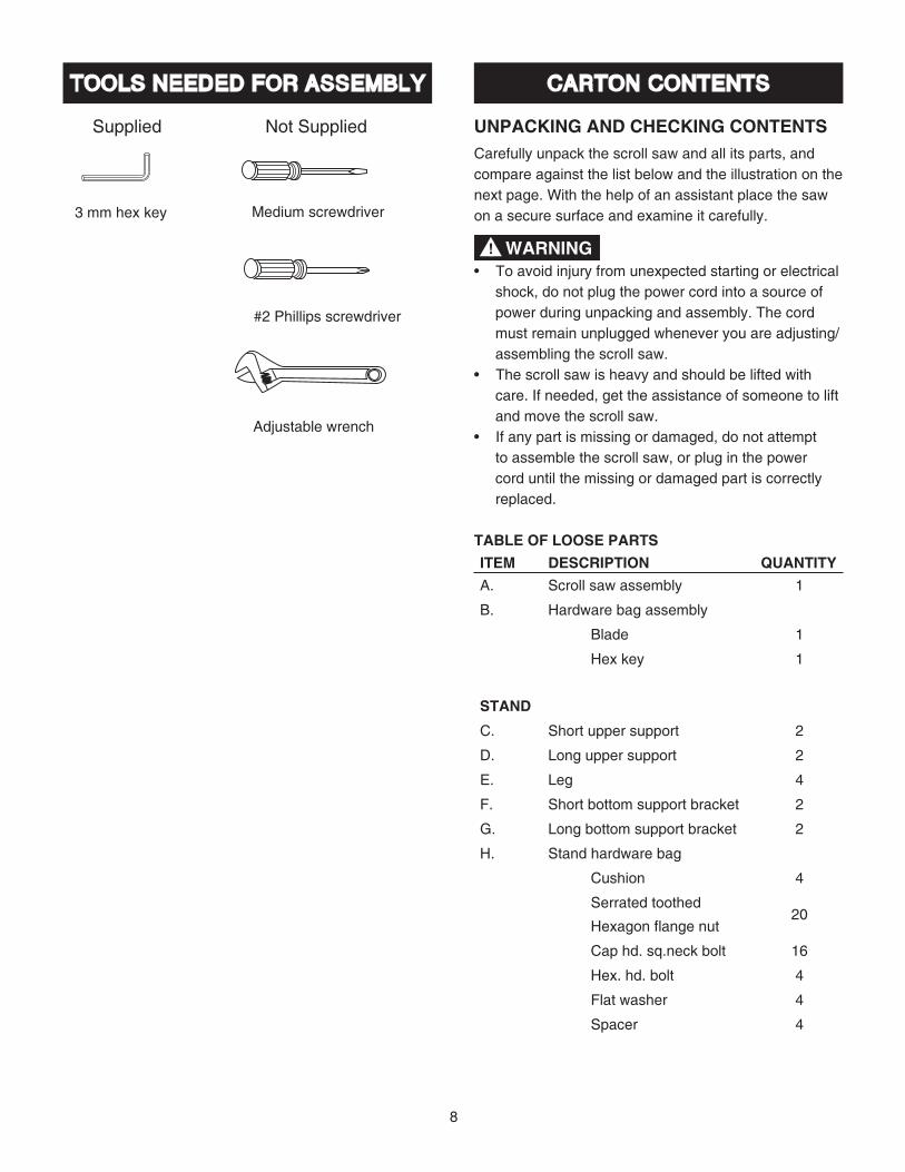
TABLE OF LOOSE PARTSITEM DESCRIPTION QUANTITYA. Scroll saw assembly 1
B. Hardware bag assembly
Blade 1
Hex key 1
STAND
C. Short upper support 2
D. Long upper support 2
E. Leg 4
F. Short bottom support bracket 2
G. Long bottom support bracket 2
H. Stand hardware bag
Cushion 4
Serrated toothed
Hexagon flange nut 20
Cap hd. sq.neck bolt 16
Hex. hd. bolt 4
Flat washer 4
Spacer 4
WARNING!
Medium screwdriver
#2 Phillips screwdriver
Adjustable wrench
3 mm hex key
9
UNPACKING YOUR SCROLL SAW
OFF
A
B
E HF G
C D

10
KNOW YOUR SCROLL SAW
Variable speed control knob
Blade guard foot lock knob
Upper arm
Blade guard foot
Quick release tension lever
Blade storage
Tension knob
Stand
Blade lock knob
Sawdust collection port
ON/OFF switch
Work light
Table lock knob
Bevel scale
Blade
Worktable
Work light ON/OFF switch
Sawdust blower
Mounting holes
11
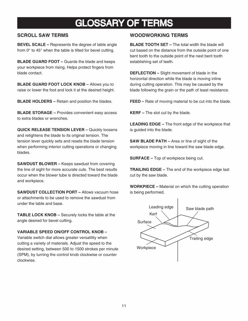
GLOSSARY OF TERMSSCROLL SAW TERMS
BEVEL SCALE – Represents the degree of table angle from 0° to 45° when the table is tilted for bevel cutting.
BLADE GUARD FOOT – Guards the blade and keeps your workpiece from rising. Helps protect fingers from blade contact.
BLADE GUARD FOOT LOCK KNOB – Allows you to raise or lower the foot and lock it at the desired height.
BLADE HOLDERS – Retain and position the blades.
BLADE STORAGE – Provides convenient easy access to extra blades or wrenches.
QUICK RELEASE TENSION LEVER – Quickly loosens and retightens the blade to its original tension. The tension lever quickly sets and resets the blade tension when performing interior cutting operations or changing blades.
SAWDUST BLOWER – Keeps sawdust from covering the line of sight for more accurate cuts. The best results occur when the blower tube is directed toward the blade and workpiece.
SAWDUST COLLECTION PORT – Allows vacuum hose or attachments to be used to remove the sawdust from under the table and base.
TABLE LOCK KNOB – Securely locks the table at the angle desired for bevel cutting.
VARIABLE SPEED ON/OFF CONTROL KNOB – Variable switch dial allows greater versatility when cutting a variety of materials. Adjust the speed to the desired setting, between 500 to 1500 strokes per minute (SPM), by turning the control knob clockwise or counter clockwise.
WOODWORKING TERMS
BLADE TOOTH SET – The total width the blade will cut based on the distance from the outside point of one bent tooth to the outside point of the next bent tooth establishing set of teeth.
DEFLECTION – Slight movement of blade in the horizontal direction while the blade is moving inline during cutting operation. This may be caused by the blade following the grain or the path of least resistance.
FEED – Rate of moving material to be cut into the blade.
KERF – The slot cut by the blade.
LEADING EDGE – The front edge of the workpiece that is guided into the blade.
SAW BLADE PATH – Area or line of sight of the workpiece moving in line toward the saw blade edge.
SURFACE – Top of workpiece being cut.
TRAILING EDGE – The end of the workpiece edge last cut by the saw blade.
WORKPIECE – Material on which the cutting operation is being performed.
Kerf
Leading edge Saw blade path
Trailing edge
Workpiece
Surface
Variable speed control knob
Blade guard foot lock knob
Upper arm
Blade guard foot
Quick release tension lever
Blade storage
Tension knob
Stand
Blade lock knob
12
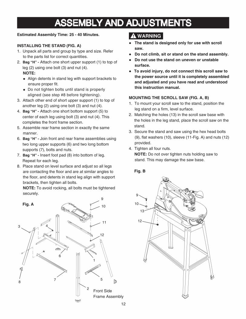
ASSEMBLY AND ADJUSTMENTSEstimated Assembly Time: 25 - 40 Minutes.
INSTALLING THE STAND (FIG. A)1. Unpack all parts and group by type and size. Refer
to the parts list for correct quantities.2. Bag “H” - Attach one short upper support (1) to top of
leg (2) using one bolt (3) and nut (4).NOTE: ● Align detents in stand leg with support brackets to
ensure proper fit. ● Do not tighten bolts until stand is properly aligned (see step #8 before tightening).
3. Attach other end of short upper support (1) to top of another leg (2) using one bolt (3) and nut (4).
4. Bag “H” - Attach one short bottom support (5) to center of each leg using bolt (3) and nut (4). This completes the front frame section.
5. Assemble rear frame section in exactly the same manner.
6. Bag “H” - Join front and rear frame assemblies using two long upper supports (6) and two long bottom supports (7), bolts and nuts.
7. Bag “H” - Insert foot pad (8) into bottom of leg. Repeat for each leg.
8. Place stand on level surface and adjust so all legs are contacting the floor and are at similar angles to the floor, and detents in stand leg align with support brackets, then tighten all bolts.NOTE: To avoid rocking, all bolts must be tightened securely.
Fig. A9
10
12
1
5
2
7
6
4
8
311
Front SideFrame Assembly
● The stand is designed only for use with scroll saw.
● Do not climb, sit or stand on the stand assembly.● Do not use the stand on uneven or unstable
surface.● To avoid injury, do not connect this scroll saw to
the power source until it is completely assembled and adjusted and you have read and understood this instruction manual.
MOUNTING THE SCROLL SAW (FIG. A, B)1. To mount your scroll saw to the stand, position the
leg stand on a firm, level surface.2. Matching the holes (13) in the scroll saw base with
the holes in the leg stand, place the scroll saw on the stand.
3. Secure the stand and saw using the hex head bolts (9), flat washers (10), sleeve (11-Fig. A) and nuts (12) provided.
4. Tighten all four nuts. NOTE: Do not over tighten nuts holding saw to
stand. This may damage the saw base.
Fig. B
WARNING!
OFF
9
10
12
13
13
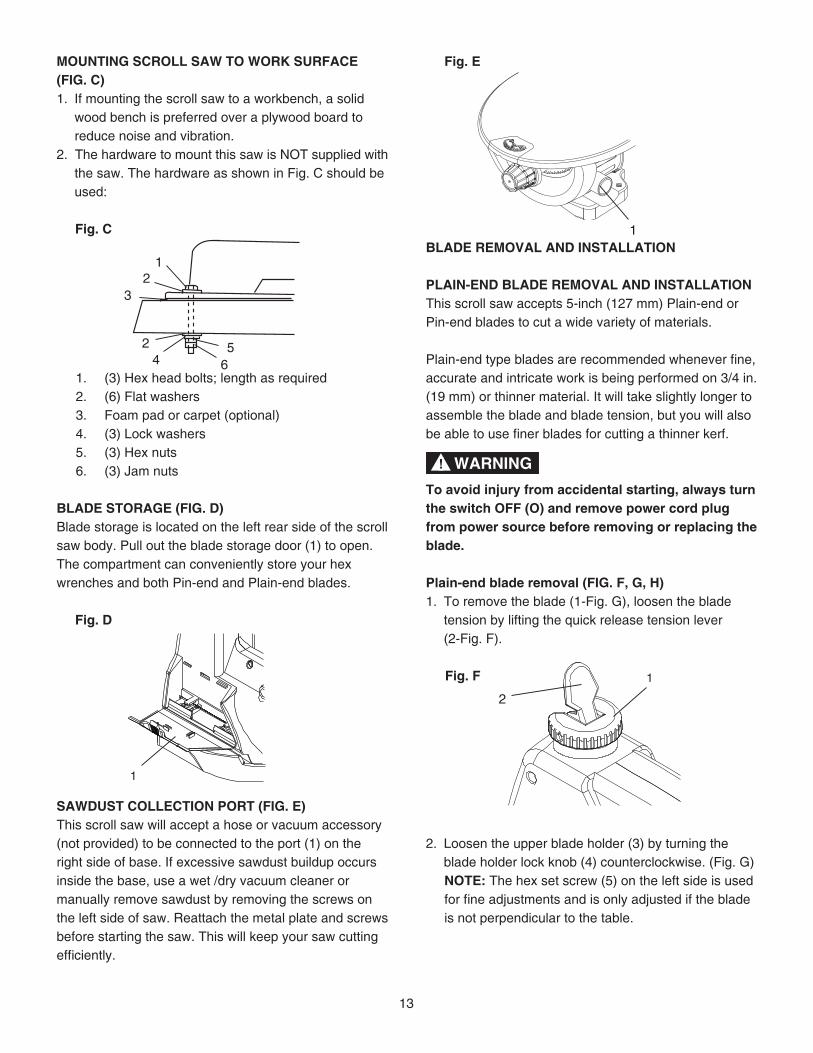
MOUNTING SCROLL SAW TO WORK SURFACE(FIG. C)1. If mounting the scroll saw to a workbench, a solid
wood bench is preferred over a plywood board to reduce noise and vibration.
2. The hardware to mount this saw is NOT supplied with the saw. The hardware as shown in Fig. C should be used:
Fig. C
1. (3) Hex head bolts; length as required2. (6) Flat washers3. Foam pad or carpet (optional)4. (3) Lock washers5. (3) Hex nuts6. (3) Jam nuts
BLADE STORAGE (FIG. D)Blade storage is located on the left rear side of the scroll saw body. Pull out the blade storage door (1) to open. The compartment can conveniently store your hex wrenches and both Pin-end and Plain-end blades.
Fig. D
SAWDUST COLLECTION PORT (FIG. E)This scroll saw will accept a hose or vacuum accessory (not provided) to be connected to the port (1) on the right side of base. If excessive sawdust buildup occurs inside the base, use a wet /dry vacuum cleaner or manually remove sawdust by removing the screws on the left side of saw. Reattach the metal plate and screws before starting the saw. This will keep your saw cutting efficiently.
12
3
56
24
1
Fig. E
BLADE REMOVAL AND INSTALLATION
PLAIN-END BLADE REMOVAL AND INSTALLATIONThis scroll saw accepts 5-inch (127 mm) Plain-end or Pin-end blades to cut a wide variety of materials.
Plain-end type blades are recommended whenever fine, accurate and intricate work is being performed on 3/4 in. (19 mm) or thinner material. It will take slightly longer to assemble the blade and blade tension, but you will also be able to use finer blades for cutting a thinner kerf.
To avoid injury from accidental starting, always turn the switch OFF (O) and remove power cord plug from power source before removing or replacing the blade.
Plain-end blade removal (FIG. F, G, H)1. To remove the blade (1-Fig. G), loosen the blade
tension by lifting the quick release tension lever (2-Fig. F).
Fig. F
2. Loosen the upper blade holder (3) by turning the blade holder lock knob (4) counterclockwise. (Fig. G)
NOTE: The hex set screw (5) on the left side is used for fine adjustments and is only adjusted if the blade is not perpendicular to the table.
1
WARNING!
2
1
14
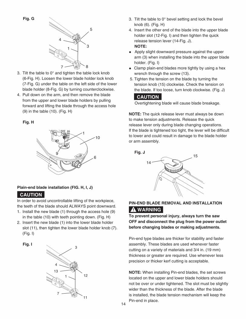
Fig. G
3. Tilt the table to 0° and tighten the table lock knob (6-Fig. H). Loosen the lower blade holder lock knob (7-Fig. G) under the table on the left side of the lower blade holder (8-Fig. G) by turning counterclockwise.
4. Pull down on the arm, and then remove the blade from the upper and lower blade holders by pulling forward and lifting the blade through the access hole (9) in the table (10). (Fig. H)
Fig. H
Plain-end blade installation (FIG. H, I, J)
In order to avoid uncontrollable lifting of the workpiece, the teeth of the blade should ALWAYS point downward.1. Install the new blade (1) through the access hole (9)
in the table (10) with teeth pointing down. (Fig. H)2. Insert the new blade (1) into the lower blade holder
slot (11), then tighten the lower blade holder knob (7). (Fig. I)
Fig. I
3. Tilt the table to 0° bevel setting and lock the bevel knob (6). (Fig. H)
4. Insert the other end of the blade into the upper blade holder slot (12-Fig. I) and then tighten the quick release tension lever (14-Fig. J).
NOTE: ● Apply slight downward pressure against the upper
arm (3) when installing the blade into the upper blade holder. (Fig. I)
● Clamp plain-end blades more tightly by using a hex wrench through the screw (13).
5. Tighten the tension on the blade by turning the tension knob (15) clockwise. Check the tension on the blade. If too loose, turn knob clockwise. (Fig. J)
Overtightening blade will cause blade breakage.
NOTE: The quick release lever must always be downto make tension adjustments. Release the quickrelease lever only during blade changing operations. If the blade is tightened too tight, the lever will be difficult to lower and could result in damage to the blade holder or arm assembly.
Fig. J
PIN-END BLADE REMOVAL AND INSTALLATION
To prevent personal injury, always turn the saw OFF and disconnect the plug from the power outlet before changing blades or making adjustments.
Pin-end type blades are thicker for stability and faster assembly. These blades are used whenever faster cutting on a variety of materials and 3/4 in. (19 mm) thickness or greater are required. Use whenever less precision or thicker kerf cutting is acceptable.
NOTE: When installing Pin-end blades, the set screws located on the upper and lower blade holders should not be over or under tightened. The slot must be slightly wider than the thickness of the blade. After the blade is installed, the blade tension mechanism will keep the Pin-end in place.
14
15
WARNING!
5
31
4
87
CAUTION
121
4
117
3
13
1
69
10
CAUTION
15
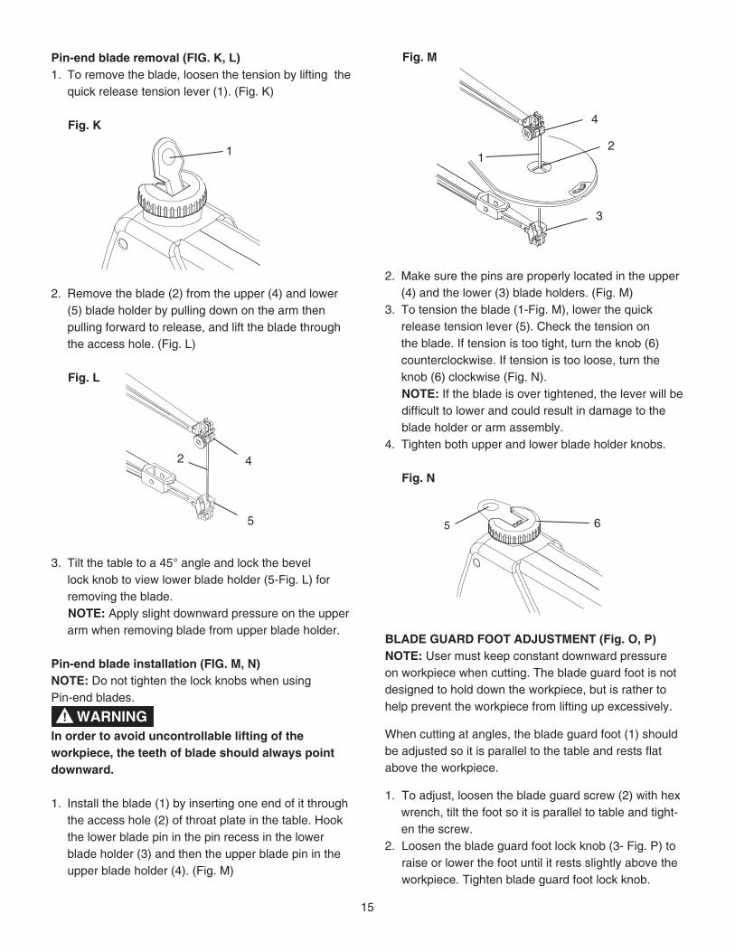
Pin-end blade removal (FIG. K, L)1. To remove the blade, loosen the tension by lifting the
quick release tension lever (1). (Fig. K)
Fig. K
2. Remove the blade (2) from the upper (4) and lower (5) blade holder by pulling down on the arm then pulling forward to release, and lift the blade through the access hole. (Fig. L)
Fig. L
3. Tilt the table to a 45° angle and lock the bevel lock knob to view lower blade holder (5-Fig. L) for removing the blade.
NOTE: Apply slight downward pressure on the upper arm when removing blade from upper blade holder.
Pin-end blade installation (FIG. M, N) NOTE: Do not tighten the lock knobs when using Pin-end blades.
In order to avoid uncontrollable lifting of the workpiece, the teeth of blade should always point downward.
1. Install the blade (1) by inserting one end of it through the access hole (2) of throat plate in the table. Hook the lower blade pin in the pin recess in the lower blade holder (3) and then the upper blade pin in the upper blade holder (4). (Fig. M)
1
42
5
Fig. M
2. Make sure the pins are properly located in the upper (4) and the lower (3) blade holders. (Fig. M)
3. To tension the blade (1-Fig. M), lower the quick release tension lever (5). Check the tension on the blade. If tension is too tight, turn the knob (6) counterclockwise. If tension is too loose, turn the knob (6) clockwise (Fig. N).
NOTE: If the blade is over tightened, the lever will be difficult to lower and could result in damage to the blade holder or arm assembly.4. Tighten both upper and lower blade holder knobs.
Fig. N
BLADE GUARD FOOT ADJUSTMENT (Fig. O, P)NOTE: User must keep constant downward pressure on workpiece when cutting. The blade guard foot is not designed to hold down the workpiece, but is rather to help prevent the workpiece from lifting up excessively.
When cutting at angles, the blade guard foot (1) should be adjusted so it is parallel to the table and rests flat above the workpiece.
1. To adjust, loosen the blade guard screw (2) with hex wrench, tilt the foot so it is parallel to table and tight-en the screw.
2. Loosen the blade guard foot lock knob (3- Fig. P) to raise or lower the foot until it rests slightly above the workpiece. Tighten blade guard foot lock knob.
4
12
3
WARNING!
5 6
16
Fig. O
SAWDUST BLOWER (FIG. P)The sawdust blower (4) should be positioned to point to the blade and workpiece to blow sawdust out of the line-of-sight when cutting. It is not designed to blow all of the sawdust off the table.
Fig. P
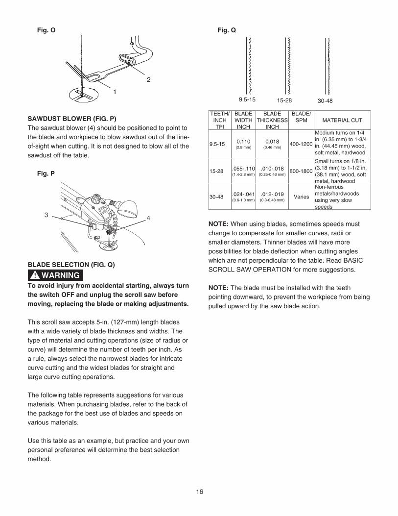
BLADE SELECTION (FIG. Q)
To avoid injury from accidental starting, always turn the switch OFF and unplug the scroll saw before moving, replacing the blade or making adjustments.
This scroll saw accepts 5-in. (127-mm) length blades with a wide variety of blade thickness and widths. The type of material and cutting operations (size of radius or curve) will determine the number of teeth per inch. As a rule, always select the narrowest blades for intricate curve cutting and the widest blades for straight and large curve cutting operations.
The following table represents suggestions for various materials. When purchasing blades, refer to the back of the package for the best use of blades and speeds on various materials.
Use this table as an example, but practice and your own personal preference will determine the best selection method.
1
2
WARNING!
Fig. Q
TEETH/ INCH TPI
BLADE WIDTH INCH
BLADE THICKNESS
INCH
BLADE/ SPM MATERIAL CUT
9.5-15 0.110(2.8 mm)
0.018(0.46 mm)
400-1200
Medium turns on 1/4 in. (6.35 mm) to 1-3/4 in. (44.45 mm) wood, soft metal, hardwood
15-28 .055-.110(1.4-2.8 mm)
.010-.018(0.25-0.46 mm)
800-1800
Small turns on 1/8 in. (3.18 mm) to 1-1/2 in. (38.1 mm) wood, soft metal, hardwood
30-48 .024-.041(0.6-1.0 mm)
.012-.019(0.3-0.48 mm)
Varies
Non-ferrousmetals/hardwoodsusing very slow speeds
NOTE: When using blades, sometimes speeds must change to compensate for smaller curves, radii or smaller diameters. Thinner blades will have more possibilities for blade deflection when cutting angles which are not perpendicular to the table. Read BASIC SCROLL SAW OPERATION for more suggestions.
NOTE: The blade must be installed with the teeth pointing downward, to prevent the workpiece from being pulled upward by the saw blade action.
9.5-15 15-28 30-48
43
17
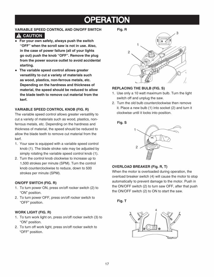
OPERATIONFig. R
REPLACING THE BULB (FIG. S)1. Use only a 10 watt maximum bulb. Turn the light
switch off and unplug the saw.2. Turn the old bulb counterclockwise then remove
it. Place a new bulb (1) into socket (2) and turn it clockwise until it locks into position.
Fig. S
OVERLOAD BREAKER (Fig. R, T)When the motor is overloaded during operation, the overload breaker switch (4) will cause the motor to stop automatically to prevent damage to the motor. Push in the ON/OFF switch (2) to turn saw OFF, after that push the ON/OFF switch (2) to ON to start the saw.
Fig. T
VARIABLE SPEED CONTROL AND ON/OFF SWITCH
CAUTION!● For your own safety, always push the switch
“OFF” when the scroll saw is not in use. Also, in the case of power failure (all of your lights go out) push the knob “OFF”. Remove the plug from the power source outlet to avoid accidental starting.
● The variable speed control allows greater versatility to cut a variety of materials such as wood, plastics, non-ferrous metals, etc. Depending on the hardness and thickness of material, the speed should be reduced to allow the blade teeth to remove cut material from the kerf.
VARIABLE SPEED CONTROL KNOB (FIG. R)The variable speed control allows greater versatility to cut a variety of materials such as wood, plastics, non-ferrous metals, etc. Depending on the hardness and thickness of material, the speed should be reduced to allow the blade teeth to remove cut material from the kerf.1. Your saw is equipped with a variable speed control
knob (1). The blade stroke rate may be adjusted by simply rotating the variable speed control knob (1).
2. Turn the control knob clockwise to increase up to1,500 strokes per minute (SPM). Turn the control knob counterclockwise to reduce, down to 500 strokes per minute (SPM).
ON/OFF SWITCH (FIG. R)1. To turn power ON, press on/off rocker switch (2) to
“ON” position.2. To turn power OFF, press on/off rocker switch to
“OFF” position.
WORK LIGHT (FIG. R)1. To turn work light on, press on/off rocker switch (3) to
“ON” position.2. To turn off work light, press on/off rocker switch to
“OFF” position.
ON
3
2
1
1
2
4
18
RECOMMENDATIONS FOR CUTTING1. When feeding the workpiece into the blade do not
force the leading edge of the workpiece into the blade because the blade will deflect, reducing the accuracy of cut and possibly breaking the blade. Allow the saw to cut material by guiding the workpiece into the blade as it cuts.
2. The blade teeth cut material ONLY on the down stroke.
3. You must guide the wood into the blade slowly because the teeth of the blade are very small and they can only remove wood when they are on the down stroke.
4. There is a learning curve for each person who wants to use this saw. During that period of time it is expected that some blades will break until you learn how to use the saw and receive the greatest benefit from the blades.
5. Best results are achieved when cutting wood less than one inch (25.4 mm) thick.
6. When cutting wood thicker than one inch (25.4 mm), the user must guide the wood very slowly into the blade and take extra care not to bend or twist the blade while cutting in order to maximize blade life.
7. Teeth on scroll saw blades wear out and must be replaced frequently for best cutting results. Scroll saw blades generally stay sharp for 1/2 to 2 hours of cutting.
8. To get accurate cuts, be prepared to compensate for the blade’s tendency to follow the wood grain as you are cutting.
9. This scroll saw is intended to cut wood or wood products.
10.When choosing a blade to use with your scroll saw, consider very fine, narrow blades to scroll cut in thin wood 1/4 in. (6.4 mm) thick or less. Use wider blades for thicker materials but this will reduce the ability to cut tight curves.
11.This saw uses 5 in. (127 mm) long pin or plain end type blades.
12.Blades wear faster when cutting plywood or particle board which is very abrasive. Angle cutting in hardwoods reduces blade tooth set faster due to the blade deflection.
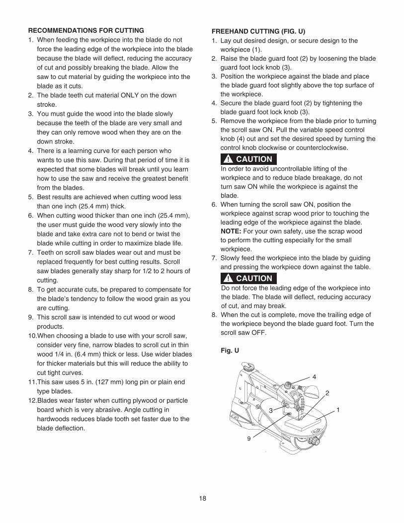
FREEHAND CUTTING (FIG. U)1. Lay out desired design, or secure design to the
workpiece (1).2. Raise the blade guard foot (2) by loosening the blade
guard foot lock knob (3).3. Position the workpiece against the blade and place
the blade guard foot slightly above the top surface of the workpiece.
4. Secure the blade guard foot (2) by tightening the blade guard foot lock knob (3).
5. Remove the workpiece from the blade prior to turning the scroll saw ON. Pull the variable speed control knob (4) out and set the desired speed by turning the control knob clockwise or counterclockwise.
CAUTION! In order to avoid uncontrollable lifting of the workpiece and to reduce blade breakage, do not turn saw ON while the workpiece is against the blade.6. When turning the scroll saw ON, position the
workpiece against scrap wood prior to touching the leading edge of the workpiece against the blade.
NOTE: For your own safety, use the scrap wood to perform the cutting especially for the small workpiece.
7. Slowly feed the workpiece into the blade by guiding and pressing the workpiece down against the table.
CAUTION!Do not force the leading edge of the workpiece into the blade. The blade will deflect, reducing accuracy of cut, and may break.
8. When the cut is complete, move the trailing edge of the workpiece beyond the blade guard foot. Turn the scroll saw OFF.
Fig. U
1
2
4
OFF
3
9

19
ANGLE CUTTING (FIG. U, V)
To avoid injury, always keep your hands off the underneath of the table during operating.
1. Lay out or secure design to workpiece (1).2. Move the blade guard foot (2) to the highest position
by loosening the blade guard foot lock knob (3) and retighten.
3. Tilt the table (5) to the desired angle by loosening the table lock knob (6) and move the table to the proper angle, using the degree scale (7) and the pointer (8).
4. Tighten the table lock knob (6).5. Loosen the blade guard screws (9-Fig. U), and tilt
the blade guard to the same angle as the table (5). Retighten the blade guard screw.
6. Position the workpiece on the left and right side of the blade (10). Lower the blade guard foot slightly above the surface by loosening the blade guard foot lock knob (3).
7. Follow items 4-8 under FREEHAND CUTTING OPERATION.
Fig. V
RIP OR STRAIGHT LINE CUTTING (FIG. W)Tools Needed (Not Included)
WARNING!
5
2
1
6
87 10
3
1. Raise the blade guard foot (1) by loosening the blade guard foot lock knob (2) on the left side of the upper arm. Measure from the tip of the blade (3) to the desired distance. Position the straight edge (4) parallel to the blade at that distance.
2. Clamp the straight edge (4) to the table (5).3. Recheck your measurements, using the workpiece to
be cut, and make sure the scrap wood (6) is secure.4. Position the workpiece against the blade and place
the blade guard foot (1) slightly above the top surface of the workpiece.
5. Secure the blade guard foot in place by tightening the foot lock knob.
6. Remove the workpiece from the blade prior to turning the scroll saw ON. Set the desired speed by turning the control knob clockwise or counterclockwise.
CAUTION! In order to avoid uncontrollable lifting of the
workpiece and reduce blade breakage, do not turn saw ON while the workpiece is against the blade.
7. Position the workpiece against the straight edge (4) prior to touching the leading edge of the workpiece against the blade (3).
8. Slowly feed the workpiece into the blade, guiding the workpiece against the straight edge and press the workpiece down against the table while cutting.
CAUTION! Do not force the leading edge of the workpiece into the blade. The blade will deflect, reducing accuracy of cut and may break.
9. When the cut is complete, move the trailing edge of the workpiece beyond the blade guard foot. Turn the scroll saw OFF.
NOTE: When cutting a narrow workpiece use push sticks.
Fig. W
QUANTITY DESCRIPTION
2 Small C-clamps
1 Ruler or measuring tape
1 12-inch (304.8 mm) -straight scrap of wood (Thickness to match workpiece)
1 A piece of wood, metal, plastic etc. with a straight edge
2
5
1
4
6
3
20
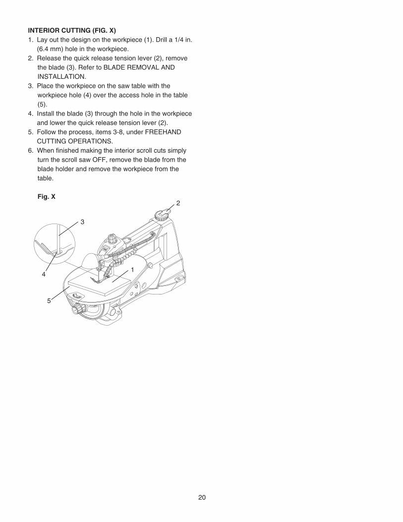
INTERIOR CUTTING (FIG. X)1. Lay out the design on the workpiece (1). Drill a 1/4 in.
(6.4 mm) hole in the workpiece.2. Release the quick release tension lever (2), remove
the blade (3). Refer to BLADE REMOVAL AND INSTALLATION.
3. Place the workpiece on the saw table with the workpiece hole (4) over the access hole in the table (5).
4. Install the blade (3) through the hole in the workpiece and lower the quick release tension lever (2).
5. Follow the process, items 3-8, under FREEHAND CUTTING OPERATIONS.
6. When finished making the interior scroll cuts simply turn the scroll saw OFF, remove the blade from the blade holder and remove the workpiece from the table.
Fig. X
5
14
2
3

21
MAINTENANCEWARNING!
For your own safety, turn the switch off and remove the plug from the power source outlet before maintaining or lubricating your scroll saw.
GENERAL MAINTENANCE
Frequently blow out dust and grit that accumulates in the motor housing using compressed air.
ALWAYS use safety glasses. Everyday eyeglasses are NOT safety glasses. Also use face or dust mask if cutting operation is dusty. ALWAYS WEAR CERTIFIED SAFETY EQUIPMENT:
• ANSI Z87.1 eye protection (CAN/CSA Z94.3),• ANSI S12.6 (S3.19) hearing protection,• NIOSH/OSHA/MSHA respiratory protection.
An occasional coat of paste wax on the work table will allow the wood being cut to glide smoothly across the work surface.
To avoid shock or fire hazard, if the power lead is worn or cut in any way, replace it immediately.
WARNING!
WARNING!
LUBRICATIONBall bearings in the scroll saw are packed with grease at the factory and require no further lubrication.
Use only mild soap and a damp cloth to clean the tool. Never let any liquid get inside the tool; never immerse any part of the tool into a liquid.IMPORTANT: To assure product SAFETY and RELIABILITY, repairs, maintenance and adjustment (other than those listed in this manual) should be performed by authorized service centers or other qualified service organizations, always using identical replacement parts.

22
ACCESSORIES AND ATTACHMENTSAVAILABLE ACCESSORIES
Since accessories, other than those offered by Porter-Cable, have not been tested with this product, use ofsuch accessories with this tool could be hazardous.To reduce the risk of injury, only Porter-Cablerecommended accessories should be used with thisproduct.
A complete line of accessories is available from yourPorter-Cable Factory Service Center or a Porter-CableAuthorized Warranty Service Center. Please visit ourWeb Site www.portercable.com for a catalog or for thename of your nearest supplier.
WARNING! Do not use any accessory unless you have completelyread the Instruction Manual for that accessory.
WARNING!

23
TROUBLESHOOTING GUIDE
To avoid injury from an accidental start, turn the switch OFF and always remove the plug from the power source before making any adjustments.
REPLACEMENT PARTSUse only identical replacement parts. For a parts list or to order parts, visit our service website at www.portercable.com. You can also order parts from your nearest Porter-Cable Factory Service Center or Porter-Cable Authorized Warranty Service Center. Or, you can call our Customer Care Center at (888) 609-9779.
SERVICE AND REPAIRSAll quality tools will eventually require servicing and/or replacement of parts. For information about Porter-Cable, its factory service centers or authorized warranty service centers, visit our website at www.portercable.com or call our Customer Care Center at (888) 609-9779. All repairs made by our service centers are fully guaranteed against defective material and workmanship. We cannot guarantee repairs made or attempted by others.You can also write to us for information at Power Tool Specialists, 684 Huey Road Rock Hill, SC 29704, (888) 609-9779 - Attention: Product Service. Be sure to include all of the information shown on the nameplate of your tool (model number, type, serial number, etc.).
WARNING!
SYMPTOM POSSIBLE CAUSES CORRECTIVE ACTIONBreaking blades 1. Wrong tension.
2. Overworking blades.
3. Wrong blade application.4. Twisting blade in wood.
1. Adjust blade tension. See BLADE REMOVAL AND INSTALLATION section.
2. Reduce feed rate. See BLADE REMOVAL AND INSTALLATION section.
3. Use narrow blade. See BLADE SELECTION section.4. Avoid side pressure on blade. See BLADE REMOVAL
AND INSTALLATION section.
Motor will not run. 1. Defective cord or plug.
2. Defective motor.
3. Blown overload breaker.
1. Replace defective parts before using saw again. See ELECTRICAL REQUIREMENTS AND SAFETY section.
2. Call Service Center. Any attempt to repair this motor may create a HAZARD unless the repair is done by a qualified technician.
3. Push the on/off switch to the OFF (O) position. Let the motor cool. See OPERATION-OVERLOAD BREAKER section.
Excessive vibration.NOTE: There will always be some vibration present when the saw is running because of motor operation.
1. Improper mounting of saw.
2. Unsuitable mounting surface.
3. Loose table or table resting against motor.
4. Loose motor mounting.
1. See mounting instructions in this manual for proper mounting technique.
2. The heavier your workbench is, the less vibration will occur. A plywood workbench will not be as good a work surface as the same size solid lumber.
3. Tighten the table lock knob.
4. Tighten motor mounting screw.
Blade run out.Blade not in line with arm motion.
1. Blade holders not aligned. 1. Loosen blade holder lock screw holding blade holder to arms. Adjust position of blade holders. Retighten blade holder lock screw. See BLADE REMOVAL AND INSTALLATION section.
For assistance with your product, visit our website at www.portercable.com for a list of service centers, or call the Porter-Cable Customer Care Center at (888) 609-9779.

24
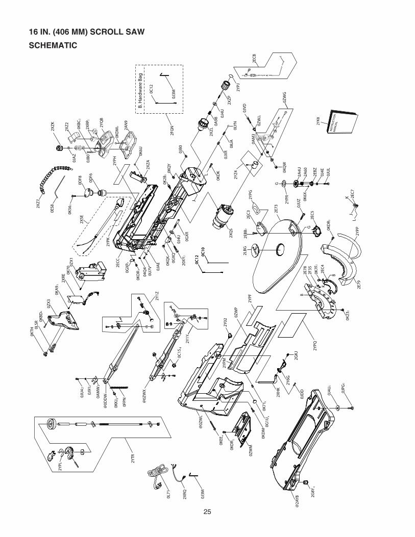
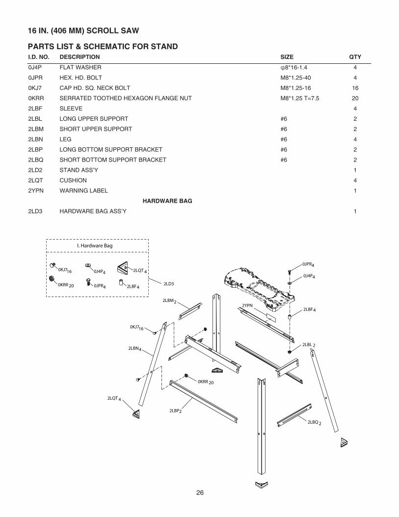
PARTS LIST16 IN. (406 MM) SCROLL SAW PARTS LISTI.D. NO. DESCRIPTION SIZE QTY I.D. NO. DESCRIPTION SIZE QTY
04Q4 STICKER 1 0ZWM BLADE BOX 108JA SPRING 1 0ZWP PLATE COVER 10A98 COMPRESSION SPRING 1 0ZWX BOTTOM ARM ROCKER #6 10AM3 WASHER D=φ9.5, φ5, T=4 1 0ZX1 CONNECTOR BOX 10AMW SET PLATE 2 0ZX3 CONNECTOR BOX COVER 10C10 BLADE 1 20XY HEX.SOCKET HD.CAP SCREWS M6*1.0-20 20C12 BLADE 1 2A4U TURNTABLE 10C15 BEARING SEAT 4 2A60 SPRING GUARD 10DDW UPPER ARM ROCKER ASS’Y #6 1 2AN9 SWITCH BOX 10DF6 BELLOWS 1 2AYB BASE #6 10DF8 PLUG HOUSING 1 2E73 TABLE #6 10ES8 PVC HOSE 1 2E78 BRACKET-TILT 10FPN EXTENSSION SPRING 1 2E79 TRUNNION BRACKET 10G1U DUST SHIELD 4 2EBB CR. RE.COUNT HD. TAPPING SCREW M5*12-16 20GXP CLAMP-CORD 4 2EBZ TURNTABLE COVER 10GXQ PLUNGER HOUSING 1 2EC3 PLATE COVER 10GXR SHAFT-PIVOT 1 2EC4 GUIDE HOLDER 10J3M HEX. WRENCH 1 2EC5 COVER 10J4E FLAT WASHER φ6*13-1 1 2EC7 GUIDE BLOCK 10J4U FLAT WASHER φ6*18-1.5 7 2ECB WIRE ROPE ASS’Y 10J91 SPRING WASHER 2 2ECC HOUSING RIGHT #GL 10JAE EXTERNAL TOOTH LOCK WASHER φ4 1 2F35 RETAINING CLIP ASS’Y 10JAZ WAVE WASHER 1 2G8Y FOOT 40JB0 WAVE WASHER 2 2GKJ HEX.SOCKET HD.CAP SCREWS M4*0.7-8 10JDD SPRING PIN 4.0-12 1 2LBG INSERT 10JPG HEX. HD. BOLT 5 2XHK HOLD DOWN ROD 10JU4 HEX. SOC. HD. CAP BOLT M4*0.7-10 2 2XQS MOTOR ASS’Y 10JUL HEX. SOC. HD. CAP BOLT M6*1.0-20 1 2XRE CONTROLLER ASS’Y 10JUZ HEX. SOC. HD. CAP BOLT M8*1.25-40 1 2XRP ROCKER SWITCH 20JVD HEX. SOC. HD. CAP BOLT M5*0.8-35 1 2XRQ LEAD WIRE ASS’Y 10JXR HEX. SOC. SET SCREW M8*1.25-8 1 2XSE LAMP ASS’Y 10K23 HEX SOC. HD. CAP SCREW M6*1.0-16 2 2XZ2 PUSH BUTTON 10K2B HEX SOC. HD. CAP SCREW M6*1.0-16 3 2XZ7 AIR DUCT ASS’Y 10K56 CR. RE. COUNT HD. SCREW 2 2XZA GUIDE CLAMP 10K6U CR.-RE. TRUSS HD. SCREW M4*0.7-8 1 2XZK INDICATED BUTTON 10K6X CR.-RE. TRUSS HD. SCREW 1 2XZL TENSION HANDLE 10K70 CR.-RE. TRUSS HD. SCREW 1 2XZP PLUNGER HANDLE 10K71 CR.-RE. TRUSS HD. SCREW 2 2Y02 HANDLE 10K7F CR. RE. ROUND WASHER HD. SCREW 2 2Y1Y HOLDER BLADE ASS’Y 10KA9 CR.RE. PAN HD. TAPPING SCREW M3*24-10 2 2Y1Z HOLDER BLADE ASS’Y 10KBC CR.RE. PAN HD. TAPPING SCREW M5*16-25 2 2Y6G FOLLOWER PLATE 10KBD CR.RE. PAN HD. TAPPING SCREW M4*18-25 4 2YK8 INSTRUCTION MANUAL 10KDK CR. RE. PAN HD. SCREW M5*0.8-16 1 2YPF LABEL 10KDM CR. RE. PAN HD. SCREW M5*0.8-20 4 2YPG CAUTION LABEL 10KDR CR. RE. PAN HD. SCREW M5*0.8-10 9 2YPH LABEL 10KEE CR. RE. PAN HD. SCREW M5*0.8-50 4 2YPJ LABEL 10KKJ CR.RE. PAN HD. ROUND NECK SCREW 2 2YPK WARNING LABEL 10KQW LOCK NUT M5*0.8 T=5 1 2YPL LABEL 10KQX NUT M6*1.0 T=6 1 2YPM LABEL 10KQY LOCK NUT M8*1.25 T=8 1 2YPP WARNING LABEL 10KTH STRAIN RELIEF 1 2YPQ LABEL 10L71 POWER CABLE 1 2YPR TILTING SCALE 1
0LSR CIRCUIT BREAKER SWITCH 1 2YQB SWITCH BOX COVER 10LYN STEEL BALL φ10 1 2YTR LINKAGE BAR ASS’Y 10U7V CR. RE. TRUSS HD. TAPPING SCREW M4*16-16 1 2YZ4 ECCENTRIC ASS’Y 10ZWG BEARING SEAT ASS’Y 1 HARDWARE BAG0ZWJ BUSH 2 2FGN HARDWARE BAG ASS’Y 10ZWL HOUSING #GL 1
25
16 IN. (406 MM) SCROLL SAW
SCHEMATIC
0C10
0C12
@2A
YB 2G
8Y4
0J3M
0J4U
50JPG
5
0KDM
0G1U
4
20K
71
0KDR
0ZWM
2
0KEE
4
0ZWP
2XRQ
0L71
@0Z
WX
0AMW
0J91
@0Z
WL
2YTR
0KKJ
0FPN
2
@0D
DW
40C
15
22
0JU4
0KTH
2
0KBD
0LSR
4
08JA
2YPF
0KQW
2YZ4
0JXR
0ZWJ 2
0ZWG
0JVD2X
ZP
0AM3
0LYN0A98
2XZL
0J4U
0JB0
04Q4 0JAE
0C10
0C12
0U7V
220
XY
0J4U
0GXQ
0GXR
0KQX
0KDR0G
XP
4
4
2ECC
0KQY
2XZA
0K2B
3
0DF6
2
0DF8
0K56
0K70
2XRE
0ZX3
0ZX1
0ES82X
Z7
2XRP
2AN9
0KDM
2YQB
30KBC
2XZ2
2
2XZK
2
2YPQ
2YPJ
2Y1Y
2Y1Z0K
A9
2
0JB0
0JAZ
2Y02
2YPH
0K6U
2LBG
G
2EBB
2YPG
0JUZ
2
2EC3
2E79
3
0K23
2
2EC4
B
B
K
2E78
0K7F
2F35
2
2E73
KJ
L
0KDR
2EC7
2EC5
2YPP
0J4E
0K6X
2EBZ
2A60
2A4U
0JUL
G
2YPR
I
2ECB
KJ
J
L
0KDK
2XHK
0JDD
2GKJ
2Y6G
2XQS
2XSE
MAN
UAL2YK8
INST
RUCTION
0C12
0J3M
B.H
ardwareBag
2FGN
2YPM
2YPL
2YPK
26
I.D. NO. DESCRIPTION SIZE QTY
0J4P FLAT WASHER φ8*16-1.4 4
0JPR HEX. HD. BOLT M8*1.25-40 4
0KJ7 CAP HD. SQ. NECK BOLT M8*1.25-16 16
0KRR SERRATED TOOTHED HEXAGON FLANGE NUT M8*1.25 T=7.5 20
2LBF SLEEVE 4
2LBL LONG UPPER SUPPORT #6 2
2LBM SHORT UPPER SUPPORT #6 2
2LBN LEG #6 4
2LBP LONG BOTTOM SUPPORT BRACKET #6 2
2LBQ SHORT BOTTOM SUPPORT BRACKET #6 2
2LD2 STAND ASS’Y 1
2LQT CUSHION 4
2YPN WARNING LABEL 1
HARDWARE BAG
2LD3 HARDWARE BAG ASS’Y 1
16 IN. (406 MM) SCROLL SAW
PARTS LIST & SCHEMATIC FOR STAND
2LBM2
2LBN4
0KJ716
0KRR 20
2LBF4
0J4P4
0JPR4
2LBL 2
2LBQ 2
2LQT 4
2LBP2
2YPN
2LD3
I. Hardware Bag
0KRR 20
0KJ716 0J4P4
0JPR4 2LBF4
2LQT 4

27
2LBM2
2LBN4
0KJ716
0KRR 20
2LBF4
0J4P4
0JPR4
2LBL 2
2LBQ 2
2LQT 4
2LBP2
2YPN
2LD3
I. Hardware Bag
0KRR 20
0KJ716 0J4P4
0JPR4 2LBF4
2LQT 4
NOTE

28
WARRANTYTHREE YEAR LIMITED WARRANTY
PORTER-CABLE will repair, without charge, any defects due to faulty materials or workmanship for three years from the date of purchase. This warranty does not cover part failure due to normal wear or tool abuse. For further detail of warranty coverage and warranty repair information, visit www.portercable.com or call (888) 609-9779. This warranty does not apply to accessories or damage caused where repairs have been made or attempted by others. This warranty gives you specific legal rights and you may have other rights which vary in certain states or provinces.
In addition to the warranty, PORTER-CABLE tools are covered by our:
1 YEAR FREE SERVICE: PORTER-CABLE will maintain the tool and replace worn parts caused by normal use, for free, any time during the first year after purchase.90 DAYS MONEY BACK GUARANTEE: If you are not completely satisfied with the performance of your PORTER-CABLE Power Tool for any reason, you can return it within 90 days from the date of purchase with a receipt for a full refund – no questions asked.LATIN AMERICA: This warranty does not apply to products sold in Latin America. For products sold in Latin America, see country specific warranty information contained in the packaging, call the local company or see website for warranty information.
To register your tool for warranty service visit our website at www.portercable.com.
WARNING LABEL REPLACEMENTIf your warning labels become illegible or are missing, call (888) 609-9779 for a free replacement.
The following are PORTER-CABLE trademarks for one or more power tools and accessories: a gray and black color scheme; a “four point star” design; and three contrasting/outlined longitudinal stripes. The following are also trademarks for one or morePorter-Cable and Delta products: 2 BY 4®, 890TM, Air America®, AIRBOSSTM, Auto-Set®, B.O.S.S.®, Bammer®, Biesemeyer®, Builders Saw®, Charge Air®, Charge Air Pro®, CONTRACTOR SUPERDUTY®, Contractor’s Saw®, Delta®, DELTA®, Delta Industrial®. DELTA MACHINERY & DESIGNTM, Delta Shopmaster and Design®, Delta X5®, Deltacraft®, DELTAGRAM®, Do It. Feel it.®, DUAL LASERLOC AND DESIGN®, EASY AIR®, EASY AIR TO GOTM, ENDURADIAMOND®, Ex-Cell®, Front Bevel Lock®, Get Yours While the Sun Shines®, Grip to Fit®, GRIPVACTM, GTF®, HICKORY WOODWORKING®, Homecraft®, HP FRAMER HIGH PRESSURE®, IMPACT SERIESTM, Innovation That Works®, Jet-Lock®, Job Boss®, Kickstand®, LASERLOC®, LONG-LASTING WORK LIFE®, MAX FORCETM, MAX LIFE®, Micro-Set®, Midi-Lathe®, Monsoon®, MONSTER-CARBIDETM, Network®, OLDHAM®, Omnijig®, PC EDGE®, Performance CrewTM, Performance Gear®, Pocket Cutter®, Porta-Band®, Porta-Plane®, Porter-Cable®, Porter-Cable Professional Power Tools®, Powerback®, POZI-STOPTM, Pressure Wave®, PRO 4000®, Proair®, Quicksand and Design®, Quickset II®, QUIET DRIVE TECHNOLOGYTM, QUIET DRIVE TECHNOLOGY AND DESIGNTM, Quick-Change®, QUIK-TILT®, RAPID-RELEASETM, RAZOR®, Redefining Performance®, Riptide®, Safe Guard II®, Sand Trap and Design®, Sanding Center®, Saw Boss®, Shop Boss®, Sidekick®, Site Boss®, Speed-Bloc®, Speedmatic®, Stair Ease®, Steel Driver Series®, SUPERDUTY®, T4 & DESIGN®, THE AMERICAN WOODSHOP®, THE PROFESSIONAL EDGE®, Thin-Line®, Tiger Saw®, TIGERCLAW®, TIGERCLAW AND DESIGN®, Torq-Buster®, TRU-MATCH®, T-Square®, Twinlaser®, Unifence®, Uniguard®, UNIRIP®, UNISAW®, UNITED STATES SAW®, Veri-Set®, Versa-Feeder®, VIPER®, VTTM, VT RAZORTM, Water Driver®, WATER VROOM®, Waveform®, Whisper Series®, X5®, YOUR ACHIEVEMENT. OUR TOOLS.®, Trademarks noted with ® are registered in the United States Patent and Trademark Office and may also be registered in other countries. Other trademarks may apply.
PORTER-CABLE and the PORTER-CABLE logo are registered trademarks of PORTER-CABLE and are used under license. All rights reserved.
Power Tool Specialists, Inc. 684 Huey Road, Rock Hill, SC 29730
(888) 609-9779www.portercable.com