Embed Size (px)
Citation preview

Aliaro reserve the right to vary from the description given in this data sheet and shall not be liable for any errors.
www.aliaro.com
16 Channels Bus Switch Board AL-2010 for SLSC
This document describes the SLSC AL-2010 board for National Instruments SLSC-12001
chassis.

Aliaro reserve the right to vary from the description given in this data sheet and shall not be liable for any errors.
www.aliaro.com
Overview
The AL-2010 (Bus Switch Board) board provides fault insertion on all common interfaces used in
a vehicle, it also provides enable or bypass for the bus signals to each ECU.
The AL-2010 board is made to fit National Instruments (NI) Switch Load Signal Conditioning
(SLSC) system together with corresponding computer interface boards and is delivered with
LabVIEW driver and custom device for VeriStand.
The main purpose if the board is to be used for test and validation of Electronic Control Units
(ECU), both software and hardware including hardware-In-the-Loop applications.
For easy configuration it’s recommended to use together Aliaro Configurator (Option). Additional
features (options) such as Ethernet to Automotive Ethernet adapter, Automotive Ethernet HUB
or LIN sensor emulator can be provided using add-on boards.

Aliaro reserve the right to vary from the description given in this data sheet and shall not be liable for any errors.
www.aliaro.com
Contents
Overview.................................................................................................................................................. 2
Description .............................................................................................................................................. 4 Detailed description ............................................................................................................................ 5
Configuration examples ...................................................................................................................... 7
Installation ............................................................................................................................................... 8 Electromagnetic Compatibility ............................................................................................................ 8
Unpacking the module ........................................................................................................................ 8
What You Need to Get Started ............................................................................................................ 8
Installing the AL-2010 .............................................................................................................................. 9 Software Installation, SLSC LabVIEW drivers....................................................................................... 9
Software Installation, Aliaro custom devices ...................................................................................... 9
Software Installation, Aliaro Configurator (Option) ............................................................................ 9
System Check ..................................................................................................................................... 10
Maintenance ......................................................................................................................................... 10 System check using LabVIEW ............................................................................................................ 10
Calibration ......................................................................................................................................... 10
Specification .......................................................................................................................................... 11 Definition and conditions .................................................................................................................. 11
Environmental Characteristics .......................................................................................................... 11
Physical characteristics ...................................................................................................................... 11
Technical characteristics ................................................................................................................... 12
Safety Guidelines ................................................................................................................................... 12
Product Certifications and Declarations ................................................................................................ 12
Environmental Guidelines ..................................................................................................................... 12

Aliaro reserve the right to vary from the description given in this data sheet and shall not be liable for any errors.
www.aliaro.com
Description
The AL-2010 (Bus Switch Board) provides fault insertion on all common interfaces used in a
vehicle, both serial interfaces such as Ethernet, RS-232, RS-485, Automotive Ethernet etc. and
bus interfaces such as CAN, LIN and Flexray
Four connectors are available at the front (Connector 1-4) to be connected to the ECU’s, the
connectors may be used in other configurations pending the interfaces used in the test setup.
AL-2010 provides fault insertion for 8 serial (2-pair) communication channels (Channel C1-C8)
and adapters (options) for Automotive Ethernet converter, Automotive Ethernet HUB and LIN
sensor emulator.
For the bus interfaces the AL-2010 supports up to four channels (B1-B4) each channel
distributed to four DUT outputs.
Figure 1, AL-2010 Block diagram

Aliaro reserve the right to vary from the description given in this data sheet and shall not be liable for any errors.
www.aliaro.com
Detailed description
Figure 2, AL-2010 Block diagram, Serial interfaces
See fig 2, For the serial interfaces the AL-2010 provides fault insertion features such as:
• Connect / Disconnect
• Short (between lines) or Normal
• Fault insertion of HI or Lo signal to + or –
•
Additional features can be provided using the add on area, see examples
Figure 3, AL-2010 Block diagram, Bus interfaces for Bus B1

Aliaro reserve the right to vary from the description given in this data sheet and shall not be liable for any errors.
www.aliaro.com
See fig 1 and 3, the AL-2010 provides four busses, each to be connected to four ECU
interfaces, those busses can be linked by software control providing other configurations such
as two busses to 8 ECU interfaces or 1 bus to 16 Ecu interfaces. Each bus can be terminated
(120 ohm) at the end by software.
Figure 4, AL-2010 Block diagram, Bus interfaces for Bus B1 B1
See fig 4, BUS interfaces the AL-2010 provides fault insertion features such as:
• Connect / Disconnect
• Short (between lines) or Normal
• Fault insertion of HI or Lo signal to + or –

Aliaro reserve the right to vary from the description given in this data sheet and shall not be liable for any errors.
www.aliaro.com
Configuration examples
Figure 5, AL-2010 Configuration example, Automotive Ethernet

Aliaro reserve the right to vary from the description given in this data sheet and shall not be liable for any errors.
www.aliaro.com
Installation
Electromagnetic Compatibility
This product is intended for use in industrial locations. However, harmful interference may
occur in some installations, when the product is connected to a peripheral device or test object,
or if the product is used in residential or commercial areas. To minimize interference with radio
and television reception and prevent unacceptable performance degradation, install and use this
product in strict accordance with the instructions in the product documentation.
Furthermore, any modifications to the product not expressly approved by Aliaro
could void your authority to operate it under your local regulatory rules.
Unpacking the module
• Carefully inspect the shipping container and the module for damage. Check for visible
damage
• to the exterior and interior of the damage. If damage appears to have been caused
during
• shipment file a claim with the carrier. Retain the packing material for possible inspection
• and/or reshipment. If the chassis is damaged, do not install it and contact Aliaro.
What You Need to Get Started
To set up and use the module you need the following items:
Hardware
• SLSC-12001 chassis
• SLSC module(s)
• Power cable
• Power input connector
• Grounding wire
• Grounding lug
Tools
• Screwdriver as needed for your application
• Wire stripper
Documentation
• SLSC-12001 Chassis Getting Started Guide and Specifications

Aliaro reserve the right to vary from the description given in this data sheet and shall not be liable for any errors.
www.aliaro.com
Caution: Do not touch the contacts or remove the I/O boards or cables while
the system is energized.
The SLSC chassis and the SLSC module do not support hot plug-in. The entire
chassis must be powered off when a module is inserted or removed.
Installing the AL-2010
1. Caution Do not touch the contacts or remove the I/O boards or cables while the system
is energized.
2. Power off the main DC power source or disconnect the power source from the chassis
before installing any modules or RTIs.
3. Ensure that the chassis is powered off. The POWER LED should be off. If the POWER
LED is not off, do not proceed until it is off.
Notice The SLSC chassis and the AL-2010 do not support hot plug-in. The entire
chassis must be powered off when a module is inserted or removed.
4. Loosen the screws on the upper rear panel of the chassis.
5. Position the RTI backplane at the desired slot and insert the securing screws, but do not
fully tighten them.
6. Insert a AL-2010 module into the same slot as its corresponding RTI while firmly holding
the RTI in place until the RTI is firmly connected to the module.
7. Repeat steps 4 and 5 for all required RTIs.
8. Fully tighten the screws for all RTIs and the upper rear panel of the chassis. Note Waiting
until all RTIs and modules are installed to fully tighten the screws ensures proper
alignment for future connections between modules and RTIs.
9. Fully tighten the two module mounting screws on each newly installed module.
10. Power on the SLSC chassis
Software Installation, SLSC LabVIEW drivers
When the module is used with LabVIEW or TestStand, Aliaro drivers need to be installed, see
Aliaro driver installation instruction.
Software Installation, Aliaro custom devices
When AL-2010 is used with VeriStand, Custom Devices needs to be installed, see the Custom
Device installation instruction.
Software Installation, Aliaro Configurator (Option)

Aliaro reserve the right to vary from the description given in this data sheet and shall not be liable for any errors.
www.aliaro.com
Aliaro configuration is recommended when large number of channels are to be configured,
both when using LabVIEW or VeriStand. See installation description Aliaro Configurator.
System Check
Finnish the installation by conducting a system check, see chapter: Maintenance
Maintenance
System check using LabVIEW
This chapter requires LabVIEW development and installation of Aliaro LabVIEW drivers
To identify and control that the cards are inserted and work properly with the right firmware,
LabVIEW provides basic VI scripts to check SLSC cards mounted in chassis
1. Open LabVIEW and select “Help” in the top menu bar and press “Find Examples…”
(This opens a new window with pre-built VI (Virtual Instruments) for different
applications).
1. Switch to the “Search” tab and enter keyword “SLSC” and double click.
2. In the new filtered table (to the right) find and select VI called “Configuration.vi”. This
VI can located every card(s) that is online in SLSC chassi.
3. To find the newly inserted cards look for the SLSC chassi IP-address (in the table to
the right).
4. Count the showing card(s) in the table and make up that there are as many mounted
in the SLSC chassi as there are in the VI table for that specific IP address. (Can be 1
up to 11 cards per SLSC chassi)
Calibration
Recommended warm-up time 10 min
Calibration interval Not required
Aliaro reserve the right to vary from the description given in this data sheet and shall not be liable for any errors.
www.aliaro.com
Specification
Definition and conditions
Warranted specifications describe the performance of a model under stated operating conditions
and are covered by the model warranty.
The following characteristic specifications describe values that are relevant to the use of the
model under stated operating conditions but are not covered by the model warranty.
• Typical specifications describe the performance met by a majority of models.
• Nominal specifications describe an attribute that is based on design, conformance
testing, or supplemental testing.
Specifications are Typical unless otherwise noted.
Specifications are valid under the following conditions unless otherwise noted.
The KADRO-AL-201016 module is mounted in an SLSC chassis with the recommended cooling
clearances and using a power supply that meets the specifications provided in the chassis user
guide. For the entire temperature range of the chassis.
Note These specifications only apply to the product as provided by Aliaro. Modifications
to the module may invalidate these. Be certain to verify the performance of modified
modules.
Caution Observe all instructions and cautions in the user documentation. Using the
model in a manner not specified can damage the model and compromise the built-in
safety protection. Return damaged models to Aliaro for repair.
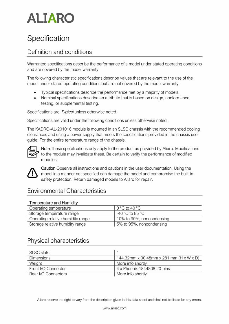
Environmental Characteristics
Temperature and Humidity
Operating temperature 0 °C to 40 °C
Storage temperature range -40 °C to 85 °C
Operating relative humidity range 10% to 90%, noncondensing
Storage relative humidity range 5% to 95%, noncondensing
Physical characteristics
SLSC slots 1
Dimensions 144.32mm x 30.48mm x 281 mm (H x W x D)
Weight More info shortly
Front I/O Connector 4 x Phoenix 1844808 20-pins
Rear I/O Connectors More info shortly

Aliaro reserve the right to vary from the description given in this data sheet and shall not be liable for any errors.
www.aliaro.com
Technical characteristics
2-pair Impedance Channel 1-4: 120Ohm
Channel5-12: 100 Ohm
Bandwith Channel 1-4: 50MHz Differental
Channel 2-12: 400MHz Differental
Isolation In open circuit
Between channels
Voltage 100V
Short circuit current: 500mA (protected by current limiter circuit)
Path resistance Channel 1-4: In to Out 2 Ω
Channel 5-12: In to Out 1 Ω
Safety Guidelines
Caution Ensure that hazardous voltage wiring is performed only by qualified personnel
adhering to local electrical standards.
Caution Do not mix hazardous voltage circuits and human-accessible circuits on the
same module
Caution When device terminals are hazardous voltage LIVE, you must ensure that
devices and circuits connected to the device are properly insulated from human contact.
Caution All wiring must be insulated for the highest voltage used.
Product Certifications and Declarations
Refer to the product Declaration of Conformity (DoC) for additional regulatory compliance
information. To obtain product certifications and the DoC for Aliaro products, visit aliaro.com/
Environmental Guidelines
Notice This model is intended for use in indoor applications only