Embed Size (px)
Citation preview

© 2015 Electric Power Research Institute, Inc. All rights reserved.
Southern California EdisonEnergy Education Center-Irwindale
June 23, 2015
Truck and Bus Charging Standards Discussion
Meeting

THIS DOCUMENT AND THE CONTENTS DISCUSSED HEREIN ARE THE CONFIDENTIAL AND PROPRIETARY INFORMATION OF NEW FLYER INDUSTRIES CANADA ULC ANDNEW FLYER OF AMERICA INC. AND ARE DISCLOSED BY NEW FLYER IN CONFIDENCE. THIS DOCUMENT AND THE CONTENTS HEREIN ARE NOT TO BE DISCLOSED BYTHE INTENDED RECIPIENT WITHOUT THE PRIOR WRITTEN AUTHORIZATION OF NEW FLYER. ANY UNAUTHORIZED DISCLOSURE, REPRODUCTION OR OTHERDISTRIBUTION OF THIS DOCUMENT OR INFORMATION IS STRICTLY PROHIBITED AND MAY RESULT IN ACTION BEING TAKEN AGAINST THE PARTY MAKING THEUNAUTHORIZED DISCLOSURE. THIS DOCUMENT AND ALL COPIES HEREOF MUST BE RETURNED TO NEW FLYER UPON REQUEST.
Battery Bus Charging Overview

Confidential Best Bus Value and Support for Life.2
On-Route Rapid Charge Station

Confidential Best Bus Value and Support for Life.3
New Flyer On-Route Rapid Charging
Design Goals Maximize rapid charging capability
− Transfer highest amount of power in shortest amount of time− Minimize efficiency losses− Shortest possible charging time required to meet operating route profile
Minimize complexity− Keep charging procedure and vehicle connection process as simple as possible− Minimize the need for complex moving parts and communication links− Produce lowest possible impact to overall bus design using established technology− Ensure easy alignment of vehicle to charge station with no special sensors or maneuvers
Provide best value economical solution Ensure operational safety & security Environmental compatibility

Confidential Best Bus Value and Support for Life.4
New Flyer On-Route Rapid Charging
Inductive Vs. ConductiveCONDUCTIVE CHARGING
Direct power contact (touches)Alignment of contacts criticalSimple data transfer optionsInherently safe (No contact = No power)High power transfer (300kW & up)High efficiencyVisible overhead structure needs styling (or may be objectionable)Lower cost relative to power output availableRequires zone where higher vehicles are prohibitedMature/reliable technology from rail industry
INDUCTION CHARGING
No direct connection (air gap)Some designs need very small gapMandatory wireless communicationRisk of unexpected/uncontrolled powerLower power transfer (50 to 200kW)Power pick-up/alignment hurt efficiencyInfrastructure is easier to keep “hidden” (but at higher cost)Overall higher costRequires induction coil imbedded into roadway (ground clearance issues)Much development work still ongoing
Conductive charging solution offers clear advantages

Confidential Best Bus Value and Support for Life.5
New Flyer On-Route Rapid Charging
Overhead Conductive Charging

Confidential Best Bus Value and Support for Life.6
New Flyer On-Route Rapid Charging
Overhead Conductive Charging

Confidential Best Bus Value and Support for Life.7
New Flyer On-Route Rapid Charging
Overhead Conductive Charging

Confidential Best Bus Value and Support for Life.8
New Flyer On-Route Rapid Charging
Operational Characteristics
• Easy start-up of rapid charging session Driver parks under overhead contacts while vehicle still running Design of overhead gantry and onboard pantograph makes setup tolerant to misalignment Driver engages switch on dash to raise pantographs Once connection confirmed, driver starts charge cycle and waits for completion Vehicle remains fully interlocked while connected to overhead charge contacts
• No further input is required from driver once charging starts All charging control handled automatically by vehicle and station State of charge (%) battery gauge on dash shows progress to driver Automatic shutdown once vehicle batteries reach full state of charge Automatic stop in the event of errors or faults Critical emergency results in automatic lowering of pantograph which immediately cuts power Driver can also easily terminate charging and resume route at any time before full charge
• Charge ends and driver is able to get back on route quickly Driver lowers pantograph and removes parking brake Interlocks disengage and drive system is fully primed and still in full run mode Driver pulls away and station is ready for next charge session as required
Use of simple, classic, mature overhead connection from rail industry
Confidential Best Bus Value and Support for Life.9
New Flyer On-Route Rapid Charging
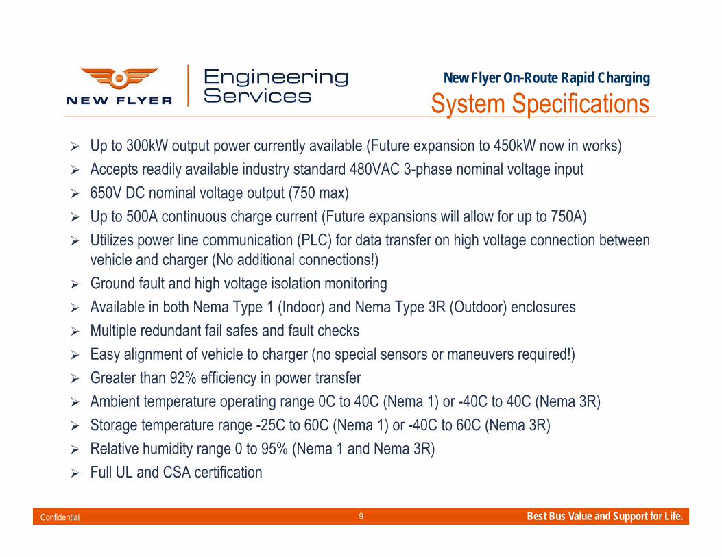
System Specifications Up to 300kW output power currently available (Future expansion to 450kW now in works) Accepts readily available industry standard 480VAC 3-phase nominal voltage input 650V DC nominal voltage output (750 max) Up to 500A continuous charge current (Future expansions will allow for up to 750A) Utilizes power line communication (PLC) for data transfer on high voltage connection between
vehicle and charger (No additional connections!) Ground fault and high voltage isolation monitoring Available in both Nema Type 1 (Indoor) and Nema Type 3R (Outdoor) enclosures Multiple redundant fail safes and fault checks Easy alignment of vehicle to charger (no special sensors or maneuvers required!) Greater than 92% efficiency in power transfer Ambient temperature operating range 0C to 40C (Nema 1) or -40C to 40C (Nema 3R) Storage temperature range -25C to 60C (Nema 1) or -40C to 60C (Nema 3R) Relative humidity range 0 to 95% (Nema 1 and Nema 3R) Full UL and CSA certification

Confidential Best Bus Value and Support for Life.10
Plug-In Depot Shop Charger
Confidential Best Bus Value and Support for Life.11
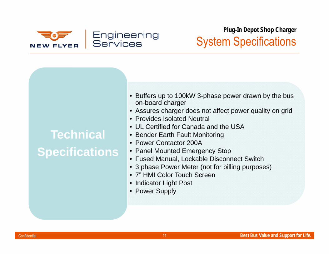
• Buffers up to 100kW 3-phase power drawn by the bus on-board charger
• Assures charger does not affect power quality on grid• Provides Isolated Neutral• UL Certified for Canada and the USA• Bender Earth Fault Monitoring• Power Contactor 200A• Panel Mounted Emergency Stop • Fused Manual, Lockable Disconnect Switch• 3 phase Power Meter (not for billing purposes)• 7” HMI Color Touch Screen• Indicator Light Post• Power Supply
TechnicalSpecifications
Plug-In Depot Shop Charger
System Specifications

Confidential Best Bus Value and Support for Life.12
Plug-In Depot Shop Charger
Operational Characteristics
How Does System Work?• One Bus at a time to be connected with charge station• Bus and charge station automatically detect each other when plugged in• Bus continuously monitors battery status – SOC, Temp etc.• Bus determines charge power required and draws as needed up to a
pre-determined maximum• Optionally, a lower charge power can be selected at charge panel• Operator triggers charging from touch screen on charge station or from
bus – Charging only proceeds when all safety requirements are confirmed
• A Ground fault or Emergency Stop button activation automatically shuts down power system.
• Charge station monitors energy amounts (kWh) transferred to bus and maintains log and summary data

Confidential Best Bus Value and Support for Life.13
Plug-In Depot Shop Charger
Design Features
Design Features• Siemens S7-1200 Class Controller, includes Ethernet networking, maintenance
free (no battery, permanent memory storage), Data logging• Siemens PAC3200 Industrial Power Meter – full energy/power meter, phase-to-
phase voltage• Automatic pre-charge system reduces battery/capacitor shock and increases
lifetime.• Industrial 7” Hi color Touch Screen for increased operator confidence and
readability.• High visibility 3 color beacon system for indication of charge(red/amber/green)• All panels are identical allowing easy and rapid deployment without
the need for re-commissioning• Emergency Stop Pushbutton

Confidential Best Bus Value and Support for Life.14
Plug-In Depot Shop Charger
Depot Charger Layout

Confidential Best Bus Value and Support for Life.15
Plug-In Depot Shop Charger
Depot Charger Layout

Confidential Best Bus Value and Support for Life.16
Plug-In Depot Shop Charger
Portable Unit Option Optional Portable Version of Plug-In Depot Shop Charger Now Available
− Rugged skid-mounted design built to be relocated to various sites as required− Still capable of up to 100kW and operates in same manner as deport configuration− Input designed for standard industrial 480VAC/208VAC 3-phase plug (selectable)− Input phase rotation is selectable and easy to configure for maximum flexibility

Confidential Best Bus Value and Support for Life.17
Plug-In Depot Shop Charger
Future Expansion
Phase 1 - Present• Buffers on-board Battery Bus
Charger from grid • Facilitates Ground Fault
detection • Provides Diagnostics and
Optional Charge level control
Phase 2 - Future• Master Controller Power Panel• Master Controller Wireless
Communication System
Phase 3 - Future• SCADA Monitoring Server

Confidential Best Bus Value and Support for Life.18
Plug-In Depot Shop Charger
Future Expansion
Garage
Master Power Distribution Panel
Controller Xcelsior
Xcelsior
Xcelsior
Siemens Industrial Access Point
Garage wireless network provides coordinated communication between the Charge Stations and the Master Power Controller.
The network is extended by the addition of WDS (Wireless Distribution System) nodes.
This enables simple, flexible extension of the wireless network as required.
The Master Power Controller is then able to cycle/control the Charge Stations to maintain the systems electrical requirements.
Xcelsior
Xcelsior
Xcelsior
Xcelsior
Xcelsior
Xcelsior
Xcelsior
Xcelsior
Xcelsior

Confidential Best Bus Value and Support for Life.19
Plug-In Depot Shop Charger
Future Expansion
Full network visibility
SQL Server data logging for highly reliable data storage.
Scalable to hundreds of Charge Stations.
All parameters and bus information within the system is available and can be stored on the SCADA Server.
Example: Individual bus serial numbers and mileage can be saved each time they are charged
WinCC SCADA Server
XcelsiorXcelsiorXcelsiorXcelsior
Master Power Panel
Charge Stations
Wireless Network


SAE TEVHYB13 1
EPRI IWC Meeting
SAE Medium and Heavy Duty Vehicle Conductive Charging Task Force
Rodney McGeeChairman
University of Delaware
June 23,24,25 2015Irwindale, California

Current Documents Under Development
• EV Power Transfer using Overhead Coupler (JXXXX)– Organizing meeting June 23 at IWC– Desire to standardize overhead charging – Helps projects where interoperability is desired– Development of scope and rational underway– Select a person to lead overhead meetings
• EV Power Transfer using Three-phase Capable Coupler (J3068)– Ongoing meetings– Document drafting underway
• Wireless charging – Covered sub-group under J2954– Need to liaison to ensure our use cases and requirements are
covered
SAE TEVHYB13 2

Joining the Task Force (TEVHYB13)
• Two documents are being developed under the SAE Medium and Heavy Duty Vehicle Conductive Charging Task Force – EV Power Transfer using Overhead Coupler (JXXXX)– EV Power Transfer using Three-phase Capable Coupler (J3068)
• Download the form to join the task force– http://bit.ly/sae-join– Return to SAE Staff: Pat Ebejer [email protected]
SAE TEVHYB13 3

SAE Transparency Statement
SAE J3068 4
This Task Force is committed to transparency at the highest level.
All topics are discussed in open meetings and decisions are consensus based (not unanimous).
Task Force members are required to be vigilant in their efforts to monitor Task Force activities and decisions by actively participating in the Task Force.
Any issues with the transparency of this Task Force not resolved by the Task Force Chairman should be brought to the attention of the SAE for resolution.

SAE Anti-Trust Statement
SAE J3068 5
In discharging their responsibilities, members of the Technical Standards Board, Councils/Division, and Technical Committees function as individuals and not as agents or representatives of any organization with which they may be associated,
except that government employees participate in accordance with governmental regulations.
Members are appointed to SAE Technical Committees on the basis of their individual qualifications which enable them to contribute to the work of the Committee.

SAE Patent Disclosure
SAE J3068 6
Each SAE Technical Committee or SAE working group member would be required to disclose at specified times during a development process all patents and patent applications that are owned, controlled or licensed by the member, member’s employer or third party and that the member believes may become essential to the draft specification under development.
The member would make this disclosure based on the member’s good faith and reasonable inquiry.
If SAE International receives a notice that a proposed SAE Technical Report may require the use of an invention claimed in a patent, the respective part of the SAE Technical Standards Board Policy will be followed.
SAE Use Discretion in Information Exchange
SAE J3068 7
Members of SAE Technical Standards Boards, Councils and Technical Committees and working groups shall be sensitive to the nature of information they share and exchange when carrying out their responsibilities.
Members are to exercise discretion at all times keeping in mind that a primary objective of their membership is to contribute to the advancement of technical and engineering science through the development of recognized industry reports and standards.
SAE is not responsible for protecting information exchanged by members, nor will SAE be liable for or mediate any dispute related to any misuse of information.

Scope of J3068
– The SAE has authorized a document for three-phase AC charging for electric vehicles
– ScopeThis document covers the general physical, electrical, functional, testing, and performance requirements for conductive power transfer to an electric vehicle using a coupler capable of, but not limited to, transferring three-phase AC power. It defines a conductive power transfer method including the digital communication system. It also covers the functional and dimensional requirements for the vehicle inlet, supply equipment outlet, and mating housings and contacts.
– Targeted towards charging at commercial and industrial locations or other places where three-phase power is available and preferred.
SAE J3068 8

J3068
• EVSE– Tested to UL-2594, UL-2231
• Three-phase capable coupler– IEC Type-2– Need to be evaluated to UL-2251
• Power levels and voltage – Voltages USA 480VAC / Canada 600VAC– Power example 160A 480VAC 3ø = 133kW
• Increase minimum “packaging room” to allow for heavier duty housings and bigger wires in the future
SAE TEVHYB13 9


![& Alternative Fuel Bus & Motorcoach Operations Session...[CNG Fuel / Electricity] CNG & BEB Charging Infrastructure(s) Electric Bus Program – Performance Experience Implementation](https://img.pdfslide.us/doc/110x75/60837a3fdf358d36a14a4223/-alternative-fuel-bus-motorcoach-operations-session-cng-fuel-electricity.jpg)