Embed Size (px)
Citation preview

15th ICCRTS “The Evolution of C2”
When Plans Change: Task Analysis and Taxonomy of 3-D Situation Awareness Challenges of UAV Replanning
Topic C2 Assessment Metrics and Tools
Authors
Maia B. Cook, Ph.D. Harvey S. Smallman, Ph.D.
Point of Contact
Maia B. Cook, Ph.D.
Name of Organization Pacific Science & Engineering Group
Complete Address
Pacific Science & Engineering Group 9180 Brown Deer Rd San Diego, CA 92121
Telephone
858-535-1661
Email [email protected]

15th ICCRTS: The Evolution of C2
1
When Plans Change: Task Analysis and Taxonomy of 3-D Situation Awareness Challenges of UAV Replanning
Abstract There are a host of human factors issues involved in operating unmanned aerial vehicles (UAVs). The challenges facing UAV operators are intensified when dynamic mission environments require route replanning on-the-fly, under time pressure. The focus of this work is to characterize the specific 3-D spatial awareness challenges encountered during UAV replanning, in order to design display and automation interventions and assistance to support replanning. To elucidate these 3-D difficulties, we conducted a cognitive task analysis of the replanning problem with the Navy’s VC-6 Squadron recently returned from Iraq. Key 3-D spatial challenges involved rationalizing complex combinations of avoiding airspace and terrain regions while simultaneously staying inside or near other airspace, target, and ground regions. Conventional UAV ground control displays did not support the integration or understanding of spatial aspects of the complex information necessary for UAV replanning. Replanning events were operationalized in terms of their 3-D spatial attributes and display requirements, and organized into a taxonomy pairing the events to replanning display interventions. A synthetic task abstraction of the key 3-D spatial replanning challenges was created, and experimentally validated. The display-to-event taxonomy guides future display designs, and experiment data and conventional displays serve as a baseline for future replanning displays. Keywords: UAV replanning, 3-D spatial awareness, UAV displays, synthetic task, replanning metrics
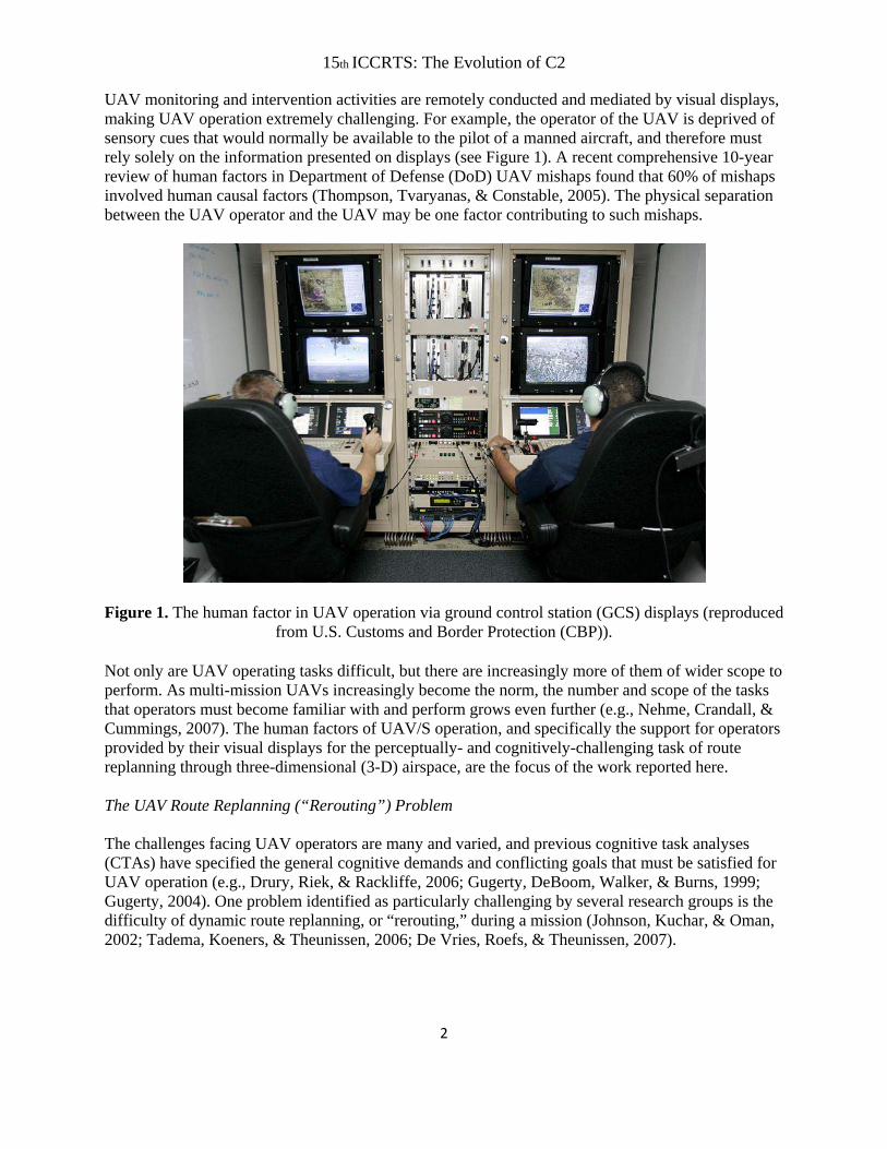
Introduction The Missing Human Factor in “Unmanned” Unmanned aerial vehicles (UAVs) are taking on an increasing array of critical tasks for the U.S. military. Their versatility, stealth, and ability to remove humans from immediate threat are all attractive attributes at a time when the military finds itself stretched in several ongoing conflicts while having to monitor emerging threats across the globe. For these reasons, UAVs and unmanned aircraft systems (UAS), more generally, figure prominently in the plans and future vision of the U.S. military (Office of the Secretary of Defense (OSD), 2005). UAVs and UAS possess a misnomer that veils a key source of issues and problems. The “unmanned” in their title suggests the twin benefits of being free of the monetary cost of human operation and the operational cost of human error. Both benefits are illusory. Although ostensibly “unmanned,” UAVs actually require constant human control, monitoring, and intervention by multiple operators per vehicle in order to operate successfully, see Figure 1. Typically, the UAV control team consists of a triad of an air vehicle operator (AVO) monitoring the flight instruments and flight path, a mission payload operator (MPO) controlling the sensors, and a mission commander communicating with air traffic control, coordinating with other mission team members, and supervising the UAV operators (Gugerty, 2004).
15th ICCRTS: The Evolution of C2
2
UAV monitoring and intervention activities are remotely conducted and mediated by visual displays, making UAV operation extremely challenging. For example, the operator of the UAV is deprived of sensory cues that would normally be available to the pilot of a manned aircraft, and therefore must rely solely on the information presented on displays (see Figure 1). A recent comprehensive 10-year review of human factors in Department of Defense (DoD) UAV mishaps found that 60% of mishaps involved human causal factors (Thompson, Tvaryanas, & Constable, 2005). The physical separation between the UAV operator and the UAV may be one factor contributing to such mishaps.
Figure 1. The human factor in UAV operation via ground control station (GCS) displays (reproduced
from U.S. Customs and Border Protection (CBP)). Not only are UAV operating tasks difficult, but there are increasingly more of them of wider scope to perform. As multi-mission UAVs increasingly become the norm, the number and scope of the tasks that operators must become familiar with and perform grows even further (e.g., Nehme, Crandall, & Cummings, 2007). The human factors of UAV/S operation, and specifically the support for operators provided by their visual displays for the perceptually- and cognitively-challenging task of route replanning through three-dimensional (3-D) airspace, are the focus of the work reported here. The UAV Route Replanning (“Rerouting”) Problem The challenges facing UAV operators are many and varied, and previous cognitive task analyses (CTAs) have specified the general cognitive demands and conflicting goals that must be satisfied for UAV operation (e.g., Drury, Riek, & Rackliffe, 2006; Gugerty, DeBoom, Walker, & Burns, 1999; Gugerty, 2004). One problem identified as particularly challenging by several research groups is the difficulty of dynamic route replanning, or “rerouting,” during a mission (Johnson, Kuchar, & Oman, 2002; Tadema, Koeners, & Theunissen, 2006; De Vries, Roefs, & Theunissen, 2007).

15th ICCRTS: The Evolution of C2
3
UAVs perform missions by flying routes through 3-D airspace. Initial routes are set up to meet mission objectives, such as gathering ISR (intelligence, surveillance, and reconnaissance) imagery, for example. Missions may entail satisfying competing goals and creating routes that satisfy a variety of often competing constraints. For example, obtaining ISR imagery may require staying close to a target to get high-quality imagery while keeping a safe distance away from the target to avoid detection. Alternatively, fuel expenditure may need to be minimized while route terrain coverage needs to be maximized. The constraint satisfaction of mission route planning is complex and requires a great deal of cognitive effort. However, the operators’ hard work is not finished once the routes have been established and these constraints have been satisfied. After initial UAV route plans have been completed and the mission has commenced, operators must monitor missions for changes that may require their intervention.
Problem
H0R1
R2
UAV1
R0
Figure 2. Illustration of the UAV rerouting problem.
As Feldmarschal von Moltke’s famous dictum states, “no plan survives contact with the enemy.” Situations inevitably unfold in unexpected ways that require operator intervention and mission replanning. Figure 2 illustrates some of the challenges of rerouting UAVs through hostile, dynamic environments, often under time pressure. In the illustration, the initial route, R0, is compromised by some problem. Alternate routes, defined through a series of waypoints (R1 and R2, for example), must be generated to route the UAV around the problem. Problems that may trigger rerouting include new enemy air defenses, weather ceiling changes, pop-up tracks requiring ISR or avoidance, airspace restrictions or openings, and vehicle malfunctions, just to name a few. The complexity of the multivariate constraint satisfaction required during rerouting, the sheer number of parameters that needs to be considered, and the importance of rapid responses for both vehicle safety and mission success combine to make rerouting a critical operator challenge. As Tadema et al. (2006) point out, the 2003 report of the Scientific Advisory Board of the U.S. Air Force on the future of UAVs concluded that UAV rerouting was a central user challenge and capability gap, stating that “… automation, human-systems interface and dynamic replanning algorithms are the key limiting factors to increasing both the performance of the UAVs and the vehicle-to-operator ratio” (United States Air
15th ICCRTS: The Evolution of C2
4
Force Advisory Board, 2003). However, the specifics of the 3-D spatial aspects of the rerouting problem have not been elucidated or studied in detail. What are the key spatial aspects of the most common problems triggering rerouting and how do operators typically handle them? Which problems are most time-pressured and how does time pressure affect rerouting in response to different triggers? What are the key cognitive and perceptual challenges and where are the potential human factors leverage points for interventions to assist users? To begin to answer these questions, we conducted a requirements analysis of the replanning problem with Navy UAV operators recently returned from the war in Iraq, and report our findings here. The Airspace Management Problem The dynamic nature of operational airspace management itself can be an additional trigger for rerouting. UAVs fly missions in a restricted operations zone (or “ROZ”) that may be shared by other manned vehicles and where other civilian and military missions may be ongoing (see U.S. Army, 2001). Within the ROZ, airspace allocated to operators may become a restricted, complex 3-D configuration to navigate through, depending on the number of ongoing missions in the region (Griffith, Wilson-Smith, Ohmer, et al., 2006). Further, airspace allocation is often dynamic, with 3-D airspace cubes, which are the units of currency of physical airspace, being given and taken away over the course of a mission and thus creating the need for dynamic rerouting when these changes impinge on UAV routes.
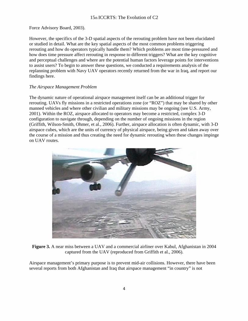
Figure 3. A near miss between a UAV and a commercial airliner over Kabul, Afghanistan in 2004 captured from the UAV (reproduced from Griffith et al., 2006).
Airspace management’s primary purpose is to prevent mid-air collisions. However, there have been several reports from both Afghanistan and Iraq that airspace management “in country” is not
15th ICCRTS: The Evolution of C2
5
proceeding smoothly or error-free (Erwin, 2005; Griffith et al., 2006). Figure 3 shows dramatic imagery captured from a German Luna UAV of a potentially catastrophic near-miss between itself and a fully-loaded commercial airliner over Kabul, where the two vehicles came with 150’ of each other (Griffith et al., 2006). Near-misses such as these indicate the potential for an airspace management failure on many levels—on the part of the airspace manager or the pilots of manned or unmanned aircraft—and may be a product of the dynamic, crowded nature of airspace that UAVs often operate within. Though operators typically do not have a common operating picture showing the locations of other manned and unmanned aircraft, they may be able to use the UAV’s live camera feed to gain some additional, though limited, situation awareness. The camera may assist somewhat in aircraft avoidance, if an aircraft in the UAV’s path is in the camera’s field of view, and if the operator sees the aircraft in time to avoid it. From the perspective of a UAV operator, what are the most significant airspace management problems? How common are they? What are their 3-D properties? Are 3-D airspace restrictions processed like any other routing constraint, or are they processed in qualitatively different ways by UAV operators, with different information and display requirements than other routing problems? Display-Related 3-D Space Perception Challenges Currently, UAV operation is mediated through ground control station (GCS1) displays. The explosion of interest in UAVs over the last decade has resulted in a variety of GCS systems provided by a number of vendors. Though there is currently a push for a standard protocol for operating multiple heterogeneous vehicles and sharing information obtained by those vehicles through a common vehicle control station (NATO Standardization Agreement (STANAG) 4586), not all UAV systems conform to this standard. Thus, current systems often display information slightly differently to UAV operators, who are then faced with learning different systems and what the different displays show. Present-day GCS displays may not support the spatial awareness needs of UAV rerouting. Current GCS systems have evolved to depict routes, track symbology and other tactical information superimposed on a display using two-dimensional (2-D) NGA (National Geospatial-Intelligence Agency) or FalconView-format maps (for an example, see Cummings, Marquez & Visser, 2007). The NGA/FalconView map format is widely used in aviation and is essentially an embellished topographic (or “topo”) map of altitude contours shown from a top-down, or 90º, viewing angle, with the addition of some shading information to provide some terrain appreciation, see Figure 2 for an example. These maps are typically segmented into square regions with the maximum terrain altitude denoted for that region. Some GCS systems also employ a separate profile view corresponding to the top-down view for checking the vertical clearance of the route over terrain. One challenge that operators face is deriving situation awareness of a 3-D airspace sufficient to perform their routing and other tasks from these 2-D topo or profile-view maps. Additionally, if both the top-down and profile-view maps are available, correspondence between, and mental integration of, the two views
1 In this report, “GCS” is used to refer to the physical ground control station, “GCS systems” refer to the system used to control UAV operations, and “GCS displays” refer to the map and informational displays within the ground control stations.

15th ICCRTS: The Evolution of C2
6
can be difficult (e.g., St. John, Cowen, Smallman & Oonk, 2001). GCS displays are employed for a large number of tasks. Each of these tasks may have different information requirements (for example, see Nehme et al., 2007). Route replanning requires spatial awareness of the 3-D airspace and terrain. There is a large and well-developed literature on the human factors of display use for spatial awareness tasks. Certain tasks are well-suited to the 2-D NGA-type map format, such as tasks requiring precise relative position judgments (St. John et al., 2001). However, awareness of the gross scene layout and shape understanding is often not well-served by 2-D displays. In particular, rapid identification of gross scene layout for path planning is better served by shaded perspective views of scenes - so-called “3-D” displays (Smallman, Cook, Manes, & Cowen, 2007; St. John, Smallman, Bank, & Cowen, 2001). It is an open question, therefore, how well current GCS displays support operators’ tasks of time-pressured rerouting through complex, constricted 3-D airspaces – challenges which are likely further compounded when terrain and target proximities impose additional constraints. Materials and Method Documenting Operator Challenges: Cognitive Task Analysis The remediation of any problem begins with its careful characterization. To characterize cognitive challenges and problems, the proven process of user-centered design begins with a cognitive task analysis or “CTA” to center remediation in the appropriate work tasks (Kirwan & Ainsworth, 1992). There are numerous methods employed across the field to perform a CTA: the current study elicited knowledge via structured interviews with actual users, a method successfully employed in the Navy’s Command 21 research program that gave rise to the Knowledge Web and Wall (Smallman, Oonk, Moore, & Morrison, 2001). The current project focuses on the demands of rerouting and developing visual displays that are well-suited to support UAV rerouting. Because of this focus and the fact that previous CTAs have specified the cognitive demands and conflicting constraints during UAV operations (e.g., Gugerty, 2004), the current CTA focused on the specific cognitive and perceptual challenges associated with the 3-D spatial aspects of rerouting UAVs. The intent was to extract sufficient information about the 3-D spatial aspects of events triggering UAV rerouting to distill down the information requirements of rerouting and relate them to the validated human factors theoretical framework of St. John et al. (2001). By identifying the shape understanding and relative position information requirements of rerouting, potential human factors leverage points for interventions and superior display-to-task pairings to assist users can be identified. The CTA will be used to develop so-called “synthetic tasks” – tasks that reflect the perceptual and cognitive demands of real rerouting tasks sufficient to allow careful lab-based human performance experimentation. Finally, results from the CTA will inform the design of UAV replanning scenarios within a testbed environment for measuring performance on the synthetic UAV re-planning task. Participants Four Navy participants (two lieutenant commanders, one chief petty officer, and one lieutenant) who were members of the Navy’s VC-6 (Fleet Composite Squadron) Shadow UAV Squadron from

15th ICCRTS: The Evolution of C2
7
Webster Field in Pax River, MD were interviewed. VC-6 was created in response to a request for forces, and the squadron recently returned from a seven-month deployment in Iraq. Structured Interview To conduct the CTA, a structured interview was developed to facilitate information elicitation about the operating experiences of VC-6 with the Shadow UAV during deployment. Respecting the limited time available to interview Navy personnel, the structured interview was designed with the minimum number of questions to quickly focus on the key issues of interest. The interview focused on events that triggered en route UAV replanning in order to document rerouting problems involving airspace, other airborne vehicles, mission requirements, and terrain. Although initial mission routing and dynamic rerouting involve some of the same issues and constraints, our efforts focus primarily on the re-routing process. Therefore, the interview focused on rerouting issues, but naturally included discussions of initial mission routing for context and complete understanding. The interview questions were grouped into the four following categories. For brevity, a representative question for each category is included in italics: 1. General UAV capabilities and functionality (four questions)
1. Example question: What routing information is typically handled automatically as opposed to manually (e.g., do you designate altitude when planning the initial route, or do you manually control UAV altitude?)
2. Rerouting event types and strategies to handle them (12 questions) 2. Example questions: What types of events occur that require you to reroute after you have
already planned an original route? How do you prioritize these events that require you to reroute?
3. Rerouting event display information (current status and future information requirements) (seven questions)
3. Example questions: Are general areas to avoid or cover shown on displays that you use for route planning and rerouting? If so, how are these areas depicted?
4. Terrain displays (current status and future information requirements) (14 questions) 4. Example questions: What types of terrain displays for routing and rerouting were available
to you during missions? What terrain display information that you did not have during your missions would have helped you plan routes and dynamically reroute?
Procedure Three participants were interviewed in April, 2008, in Pax River, MD, and one participant was interviewed at the U.S. Navy’s Third Fleet facility in San Diego, CA in August, 2008. The three VC-6 UAV operators interviewed in Pax River had operated in Baghdad and Sadr City, Iraq, and the one UAV operator interviewed in San Diego had operated near Mosul, Iraq. At the beginning of the interviews, the participants were informed of the institutional review board (IRB) approval of the interview, and the voluntary nature of their participation. The operators were informed that the purpose of the interview session was to gain an understanding of the tasks and issues faced by the squadron, especially those related to UAV path replanning,

15th ICCRTS: The Evolution of C2
8
including the types of events that trigger the need to reroute and the displays used during rerouting. Extensive notes were taken to document the operators’ responses and supplemental drawings during the interviews. The majority of the interview questions were covered during the session. The operators provided their contact information, and offered to provide additional input once the interview notes were summarized. At the end of the interview, the operators were thanked for their participation. Method of Analysis Following the interview session, the summarized responses and follow-up exchanges with the operators were reviewed and subjected to content analysis. The essential issues were distilled and categorized, and then supplemented and contextualized with information from the DoD roadmap and other relevant literature. The categorized results are presented in the next section. To further distill the results into an actionable guide for the development of the synthetic UAV rerouting task, the CTA-derived operator knowledge has been transformed into a rerouting event taxonomy (Figure 5) that includes the goals of the rerouting event, event attributes, 3-D spatial information requirements of the event, and potential human factors leverage points for interventions to assist users. Results Following the content analysis, the results were organized into the following four sections:
1. Background (provides information about the VC-6 squadron, the Shadow UAV capabilities, airspace management, and air traffic control);
2. Rerouting Events Encountered and Associated Issues (categorizes and describes the rerouting events reported by the operators and associated issues, including the impact of terrain on rerouting);
3. Rerouting Prioritization Goals and Strategies (describes how the operators prioritized during rerouting);
4. Desired Properties of UAV Display Tools and Aids (summarizes the properties of UAV display tools and aids requested by the operators, grouped by rerouting event).
1. Background
A. UAV Operator Background and Training The VC-6 trained at Fort Huachuca, AZ, with training primarily focusing on visual recognition of military vehicles. General training lasted approximately six months, consisting of five months of flight instruction, one month of new equipment training, and a two-week theater indoctrination Navy Individual Augmentee Combat Training course. Officers in charge completed approximately nine weeks of a Warrant Officer course on Army regulations and system operations.
B. Local Mission Context and Attributes During their seven-month deployment to Iraq, the airspace in the operating area of the Baghdad / Sadr City squadron was extremely crowded. Flight time averaged 18 hours per day. During the last

15th ICCRTS: The Evolution of C2
9
month and a half of their deployment, an increase in manning for AVOs allowed a transition to a continual, 24-hour operational tempo. Normal missions lasted from five to six hours, and were often at night in response to ISR requests. The missions flown by the squadron were reactive, customer-driven, and involved serving as ISR assets for counter-insurgency in the areas of Baghdad and Sadr City. The operators noted the limited transfer of their Fort Huachuca training to their mission focus of trailing generic vehicles through urban terrain. The squadron received tasking from elements requesting ISR via mIRC (multi-user internet relay chat) chat, a commonly employed military communication system. Mission planning was rarely formalized and missions tended to be fairly ad hoc. A flight plan was always entered to satisfy procedure requirements, but flight routes were flown manually or by using “points-nav,” which consisted of typing in coordinates or clicking on waypoints to designate a route. Initial mission requirements usually involved getting airborne to await subsequent specific mission tasking. The mission commander relayed and managed airspace ahead of the UAV. An airborne handoff occurred between vehicle launch controllers and main mission UAV controllers via secure line-of-sight (LoS) radio. Flight conditions were hampered by the demands of local airspace control and the need to prevent conflict with manned and fellow unmanned assets. The GCS systems for the Shadow (and other UAVs) used by the operators were not intended to give a comprehensive display of the immediate environment surrounding the UAV, including airspace availability and the location of other unmanned and manned aircraft. Therefore, the rerouting concerns were chiefly caused by the constantly changing airspace configuration, fluid mission structures, limited awareness of other aircraft, and the dynamics of a counter-insurgency combat environment.
C. Shadow UAV Capabilities and Functions
The VC-6 operated the RQ-7B Shadow UAV (for details and specifications, see OSD, 2005). In brief, the vehicle has an endurance of seven hours, an operational ceiling of 15,000 feet, a maximum speed of 105 knots, and a typical loiter speed of 60 knots. The B model is capable of accommodating the high-bandwidth TCDL (tactical common data link) and features many improvements over the original A model, including a longer wingspan, greater endurance (due to greater fuel capacity), and an improved flight computer. The system is designed purely for ISR operations and has no offensive capability.
D. GCS Display Suite
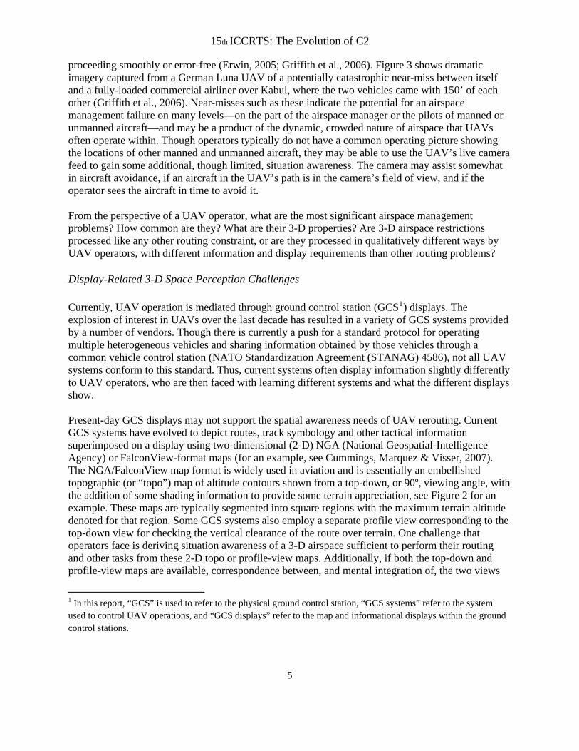
Various GCS systems can be used to control the Shadow. The VC-6 used CDL’s VCS-4586 control software during their deployment (CDL Systems, 2008). The VCS-4586 is an integrated command, control, and information system for controlling and monitoring UAS (Sulmistras & Kharey, 2008). Among its capabilities and features are integrated real-time video, an interactive map, mission planning and vehicle management, operational safety, and deployment and integration. Though the system has the ability to show top-down and profile displays of terrain, terrain maps for the VC-6 mission area were often not available for import into the control software during the operators’ missions due to IT constraints imposed by the operational environment. The video, map, mission planning, vehicle management, and operational safety windows of the VCS-4586 control display are
15th ICCRTS: The Evolution of C2
10
shown in Figure 4.
Figure 4. VCS-4586 UAV control display (from Sulmistras & Kharey, 2008).
E. Airspace Management and Air Traffic Control
Operators reported that many of their challenges resulted from the busy airspace in the area of operations. Consistent with U.S. military doctrine, mission airspace for the VC-6 was divided into “keypad” blocks defining lateral and altitude parameters to manage airspace usage for both manned and unmanned aircraft in the mission area. Each block had a fixed width and length in distance, and extended in fixed-sized altitude blocks. Multiple keypad blocks were stacked to cover the entire altitude range of the mission airspace. Numbers or letters were used to refer to the airspace cubes.
The launch site airspace that was controlled by the local airport tower and approach and departure control was also divided into regions, and was referenced with numbers or letters. For the operators, airspace management was often complicated by the fact that launch site airspace and mission airspace overlapped. This required the aircraft to be controlled initially by the launch site controller, and then be handed over to the mission controllers before the launch was technically complete. Airspace allocations had to be negotiated via website and mIRC chat rather than verbally or via the GCS. Adding to the airspace complexity was the fact that the square regions designated on the NGA maps did not correspond to the keypad squares used to designate the mission airspace. The control of the Shadow UAVs was complicated by the fact that there was no way to display the current exact location of the mission UAV to the mission commander, who was situated outside the GCS. As one operator put it, the situation was “…challenging for the mission commander sitting outside of GCS but within 5 feet of the GCS, and yet we did not have any way to display to him the current exact location of the mission A/V (air vehicle) for requesting airspace or addressing airspace control issues…” Thus, the UAV location updates had to be communicated via intercom by the AVO to the mission commander since there was no shared visual display between the mission commander

15th ICCRTS: The Evolution of C2
11
and the AVO. This required constant communication to ensure that the commander was up to date on the vehicle’s location, what airspace was open, and where other vehicles were. Complicating matters further was the fact that operators did not have a common operating picture of other airborne assets, so the position of other aircraft had to be coordinated manually by passing coordinates via radio. Even though the mission operations center could track friendly assets, this information either was not accessible by the AVO in the GCS, or was available via a separate means, such as a laptop, and its update rate was not fast enough to provide the necessary support to the operators. Thus, they often did not know where other aircraft were. This made performing a UAV handoff especially challenging: operators indicated that they only knew the actual location of a new UAV once they took control of it. One operator expressed this lack of positional knowledge by stating, “…it would be tremendously useful for either GCS to transmit location info to the other or receive locational data direct from a second A/V (air vehicle) not under that particular GCS’s control...” All of these factors added to the overall complexity of the tasks, and required constant vigilance from the operators. Though they used the live camera feed primarily for ISR, target tracking, locating, and verifying the target, the operators mentioned additional uses, such as aircraft avoidance, a back-up navigational device if GPS failed, and a means to look for icing on the leading edge of the wing and to do a local weather scan in the vicinity of the UAV. Although some of the airspace awareness issues impacting the VC-6 resulted from a lack of adequate IT coverage and thus may not apply to all UAV operations, such a lack of visualization both organic to the UAV and inherent in the GCS meant that visualizing where objects were and what events implied and entailed was exceedingly difficult. 2. Rerouting Events Encountered and Associated Issues The structured interview focused heavily on events that required the operators to reroute UAVs. The operators indicated that the need to reroute arose frequently during their missions, with the Baghdad/Sadr City operators estimating an average of 10 times per five-hour mission. Rerouting was most often triggered by operational factors, with the most common event being target tracking, followed by changes in airspace status, and other factors such as collision avoidance with other aircraft, and counter-detection requirements (ensuring that the UAV remained undetected by insurgents during counter-insurgency operations). Rerouting was also triggered by environmental events such as weather. Operators noted that, during rerouting, time pressure was generated by the need to monitor multiple sources of information, including airspace management and chat. Detailed descriptions of the types of rerouting events encountered by the VC-6 operators are described next. For each event triggering rerouting, the following essential elements that help define the synthetic tasks are specified:
Spatial aspects of primary rerouting goal: the goal achieved by successful rerouting, stated as an action (e.g., avoid or stay within) related to a spatial region (e.g., restricted airspace, target region)
Relative frequency of rerouting event: how often the rerouting event was encountered relative to other rerouting events
Potential human factors (HF) leverage point: possible human factors display intervention that

15th ICCRTS: The Evolution of C2
12
addresses a current gap and is intended to effectively support the rerouting goal
Though the operating environments and conditions were different for Baghdad/Sadr City vs. Mosul, the set of rerouting event triggers were similar across the two environments. Airspace was less congested in Mosul, so the operators dealt less with changes in airspace availability and aircraft avoidance, and terrain, and more with adverse weather compared to the Baghdad/Sadr City operators. The Mosul squadron had better access to area maps and the ability to overlay the launch site and mission airspace boundaries on their displays. The following results represent a combination of responses from the operators who worked in both environments.
A. New or Changes to Target Tracking Requirements The UAVs’ primary mission was to track targets to supply real-time intelligence to those in command. Pop-up tracks were sometimes assigned suddenly after a UAV was airborne, which at times required a complete change in mission and route. Tracking moving targets depended on the movement of the target, and often dictated the UAV’s route. Events such as friendly convoys hit by IEDs (improvised explosive devices) triggered ISR requests for locations nearby and prompted rerouting and mission changes. The operators indicated that the requirement to track or cover a moving target was the most frequent rerouting event encountered. Requests for new target track requirements, specifically tracking vehicles (“vehicle follows”) had to be initiated quickly because of the need to first receive approval for the airspace needed for tracking.
Spatial aspects of primary rerouting goal: stay within line of sight (LoS) region for target ISR
Relative frequency: high
Potential HF leverage point: specify optimal coverage of target in 3 dimensions
B. Change in Airspace Availability and Clearance Changes in the status of airspace often triggered rerouting. Inactive airspace sometimes became available for use. More commonly, though, available airspace occupied by, or in the planned route of, the UAV was closed suddenly, blocking a path or requiring the UAV to vacate. For example, so-called “hot airspace” (the airspace over a strike area) at times required immediate additional assets or manned assets to enter and traverse the area, thus closing the airspace for use by unmanned vehicles. The operations area was heavily impacted by multiple groups conducting missions. Other organizations occasionally established restricted zones for their own operations, requiring UAVs to suddenly be removed from an area as manned aerial assets entered. Also, sudden changes in the status of airspace adjacent to the UAV’s current location at times immediately triggered a rerouting requirement without prior warning. Changes in airspace availability were among the most frequent triggers for rerouting. Interestingly, operators reported adapting to the chaos of dynamic restricted airspace by developing strategies of their own. For example, they reported “grabbing more airspace than needed” to provide

15th ICCRTS: The Evolution of C2
13
themselves a buffer zone in anticipation of future restrictions. Alternatively, they sometimes had the mission commander deconflict airspace ahead of the AVO, and had the UAV loiter as close as possible to the boundary of desired airspace in anticipation of it opening up. Operators also claimed airspace squares on the way back to the airport as a contingency route.
Spatial aspects of primary rerouting goal: avoid restricted airspace region while staying within available airspace region
Relative frequency: high
Potential HF leverage point: make airspace boundaries explicit; show available and closed airspace
C. Aircraft Avoidance
At the time of their deployment, the VC-6 operated in the busiest airspace in the world. Manned and unmanned aircraft competed for tightly controlled cubes of air for performing their missions. This often resulted in the need to deconflict airspace when two aircraft were close together. Manned aircraft always received priority over unmanned vehicles, so the operators needed to reroute the UAVs to give manned aircraft priority. Operators had to respond particularly quickly in situations where a UAV was in the way of a manned aircraft. Additionally, the operators would need to occasionally avoid overhead aircraft firing at the ground through the airspace occupied by their UAV. Operators reported that, due to the congested airspace, near-misses involving UAVs occurred, sometimes with another UAV or a manned aircraft. It was possible for a UAV to stray in front of a manned asset if it, or the manned aircraft, was in the wrong altitude, keypad, or both, and was not in communication with the appropriate controlling authority.
Spatial aspects of primary rerouting goal: avoid airspace region occupied by other aircraft
Relative frequency: high
Potential HF leverage point: make location of other aircraft explicit; provide airspace transit times, distances and relative position
D. Counter-Detection Requirements
At times, when stealth was required during an ISR mission, UAV operators had to ensure that the UAV was not detected auditorily or visually by people in the vicinity of where the UAV was tracking. Operators were sometimes notified that their UAV was at risk of being detected by reports from U.S. military teams on the ground in the mission area. To prevent detection by those on the ground, operators manually changed altitude, usually flying higher.
Spatial aspects of primary rerouting goal: avoid detection region
Relative frequency: low
Potential HF leverage point: convey shape understanding of counter-detection regions and their relation to terrain

15th ICCRTS: The Evolution of C2
14
E. Weather Avoidance Though weather was not a major factor for the VC-6 because of the time of year of their deployment, operators noted that the Shadow’s capabilities are weather-limited. Shadows are susceptible to icing while in the clouds, can be outrun by sandstorms travelling faster than the UAV, and cannot fly in rain. If encountered, such changes in weather could effectively close-off airspace and require a reroute. Operators reported that different types of weather typically required different methods of avoidance. For example, icing could be avoided by changing altitude, while sandstorms could require complete avoidance of the affected area. Forced changes in altitude in response to icing (or other weather conditions) could affect LoS to the GCS for radio control, and could compromise auditory stealth required to avoid detection.
Spatial aspects of primary rerouting goal: avoid weather region
Relative frequency: low
Potential HF leverage point: convey location and shape of hazardous weather events
F. Impact of Terrain on Rerouting Events Although the VC-6 operated in an area that was mostly flat, a number of terrain issues were discussed and identified. The most important terrain information need was to understand the overall shape and altitude of the terrain. This was necessary to ensure terrain avoidance in both the absence and presence of other events (e.g., weather avoidance). In other words, even if airspace was open and no targets needed to be tracked, terrain still had to be understood to avoid colliding with it. The operators indicated that the Shadow did not have a controlled flight into terrain (CFIT) warning feature. Although some UAV systems warn of impending terrain collision, they must provide sufficient warning for the operator to recover in time. Thus, an operator’s understanding of terrain layout may be critical to recognize the need for, and execute, a successful avoidance maneuver when enough warning to recover is not provided. Also, the appropriate avoidance maneuver must be specified. For example, a sudden and steep enough climb to avoid terrain may not be physically achievable by the UAV, and other maneuvers, such as lateral turns, may be sufficient to avoid terrain. Again, an operator’s understanding of terrain layout would help to ensure selection of the proper avoidance maneuver. For the VC-6, most rerouting maneuvers involved altitude reductions rather than lateral changes because lateral changes required more time than altitude changes due to the Shadow’s slow speed. The operators indicated that understanding terrain shape was especially important for maintaining auditory and visual counter-detection. Interestingly, there were different thresholds for auditory and visual ground-based detection depending on the time of day, the ambient noise, and the seasonal behavior of the local population (e.g., the practice of sleeping on roofs in the summer, but not the winter, increases the chances of auditory detection of UAVs overhead). Terrain understanding was also critical for ensuring necessary LoS to both the targets being tracked and the ground control datalink. For example, terrain could occlude LoS between the UAV and the targets, and the radios that linked the UAV to the ground control stations could be blocked by terrain features, trees, or buildings. This, combined with the need to remain unheard and unseen, meant that
15th ICCRTS: The Evolution of C2
15
there was a practical limit to how low in altitude the UAV could be operated. The VC-6 used either NGA or FalconView maps with minimal terrain shading and altitude clearance numbers as primary terrain displays. These displays provided at best only three levels of static zoom. The global navigation chart view (GNC) allowed an overall view of theater terrain, including prominent cities, towns, drainage, roads, railroads, shaded relief, and spot elevations. The operational navigation chart view (ONC) provided a mid-level view of the theater in addition to some tactical detail, such as airports, elevations, vertical obstructions, terrain, restricted areas, and landmarks. The tactical planning chart view (TPC) showed the most detail, sufficient to support high speed, low altitude radar and visual navigation of high performance tactical and reconnaissance aircraft. Meteorological information could not effectively be overlaid on the maps. The operators indicated that access to all three views was limited at times during their missions, and these views were not scalable (e.g., no zooming between GNC and ONC). Although terrain itself is not a dynamic rerouting trigger, terrain must always be considered during rerouting, and it often interacts with rerouting events that arise (e.g., avoiding terrain may become more difficult when weather reduces the flight ceiling). The operators mentioned that other units who had operated in high-altitude mountainous areas had faced such issues.
Spatial aspects of primary rerouting goal: avoid collision with terrain; avoid LoS occlusion from terrain; land safely on terrain
Relative frequency: constant
Potential HF leverage point: convey both shape understanding about terrain and precise relative position information about distances
3. Rerouting Prioritization Goals and Strategies Operators indicated the following goal prioritization they used when they encountered events that required them to reroute. This prioritization order of goals was:
Safety of manned aircraft Airspace management Primary mission requirements A/V safety Other mission and ISR requirements
Several constraints related to the health and safety of the UAV, and other aircraft or people, had to be satisfied during UAV operations. When replanning a route, operators reported considering the following constraints, ordered roughly from most to least important:
Safety and ability to maintain control of UAV Fuel status Airspace needs and availability Airspace deconfliction with other assets Planning UAV return to home base and turnover to new UAV

15th ICCRTS: The Evolution of C2
16
Maximum airspeed limits Terrain (as a collision hazard and a potential source of signal masking) Weather
4. Desired Properties of UAV Display Tools and Aids Not surprisingly, several of the properties of UAV display tools and aids desired by the operators related to the gaps in available information relevant to rerouting events. The desired properties are organized according to rerouting event categories. The purpose of eliciting these properties from the operators was to gain additional insight into their tasks and the information they believed would help to support those tasks.
Airspace Availability and Clearance
The operators indicated a need for user-activated overlays to display the boundaries and availability of airspace areas. One operator suggested simplifying the process of requesting keypads by typing the desired keypad into a system and receiving clearance for approved keypads: “…operators should not be required to build all of this; at the beginning of the flight, it should be as easy as entering in a list of keypads.” The use of highlighting for designating their own airspace and the opening of previously-closed airspace was also proposed: “…your airspace would be highlighted, as well as restricted (hot) areas as they become active.”
Aircraft Avoidance Operators expressed a need for a representation of other aircraft, designated by type (friendly, manned, or unmanned) in real-time: “…knowing where the other aircraft are, and their parameters (altitude, airspeed, heading, and aircraft type) is crucial in a saturated air environment…” Also, the ability to filter aircraft location by altitude was noted as important. Operators wanted to be able to show or hide the positions of other aircraft to reduce clutter when necessary.
Terrain The operators stated that a user-activated terrain overlay would be useful, especially when terrain becomes a factor (e.g., when it comes within a certain number feet of the UAV). They also thought that a LoS indicator to show terrain that would mask the control signal if the UAV went below a certain altitude would be useful. A display to show areas where the terrain could mask the control signal given the UAV’s present altitude was also recommended. Additionally, the operators indicated that a 3-D display with a variable viewing angle, or a separate top-down display with a corresponding profile view, would be useful.
Weather The operators indicated that it would be useful to selectively overlay current radar and satellite information for thunderstorms, rain, dust, cloud layers, and freezing temperature boundaries on UAV control displays.
15th ICCRTS: The Evolution of C2
17
Conclusions Interviews with the VC-6 operators revealed the challenges involved in UAV control, monitoring, and intervention. This particular group of operators constantly dealt with the challenges of dynamic UAV rerouting in an exceptionally busy and complex environment, and had to satisfy multiple and often competing constraints during rerouting. Airspace management was especially difficult during their missions as there was no common operating picture to coordinate understanding of own and other aircraft locations. Rerouting events were commonly encountered during missions, with new targets or changes to target tracking requirements being most frequent, followed by changes in airspace availability and clearance, aircraft avoidance, terrain issues, counter-detection requirements, and weather avoidance. Unsurprisingly, rerouting was reported as most time-pressured for the most time-critical dynamic events, such as a new target or a change to a target being tracked (requiring clearance to airspace to track the target) and aircraft avoidance. The key spatial aspects of most rerouting events were combinations of avoiding closed or dangerous regions while staying inside of, close to, or within sight of regions of interest or those crucial for UAV control (e.g., LoS to GCS). Regions of space to avoid and enter generally had complex configurations and sometimes overlapped (e.g., target LoS region and counter-detection region). Understanding the 3-D aspects of the UAV route, the location of other aircraft in 3-D space, the airspace boundaries, target location, weather, terrain shape, and the interaction of all of these factors is critical for UAV rerouting. 3-D space perception challenges were present for all types of rerouting events discussed with the operators, exacerbated by the lack of display support for these tasks. The challenges faced by the operators indicate a need for displays that support the understanding of the 3-D aspects of rerouting to enable effective rerouting. Also, solutions that integrate automation, such as artificial intelligence-based path planning algorithms (PPAs) to assist users with developing and selecting optimal reroutes, would provide further support. It is the aim of this line of research, in collaboration with MIT, to develop methods for effectively visualizing the outputs of such PPAs to support dynamic rerouting. Mission experiences will vary depending on the type of UAV being flown, the environmental conditions (terrain and weather), and the specific mission objectives. The similarities in rerouting events for the two VC-6 groups who operated in different environments suggest that such rerouting events are likely to generalize to other UAV missions. Further, the generic categories of abstracted spatial attributes for those rerouting events apply across missions and environments, and to additional replanning considerations that may arise in the future (e.g., counter-air threats could be reduced to restricted regions of airspace to avoid). Codifying the Issues: Rerouting Event Taxonomy and Synthetic Task The purpose of the structured interview was to understand the issues that UAV operators face during in-flight UAV rerouting to support the development of synthetic rerouting tasks. An additional goal was to use this knowledge of the issues as a basis for development and testing of display solutions to support effective UAV rerouting. To codify the domain knowledge gained from the interviews, and to structure and support the study of UAV rerouting, the issues and events extracted from the interviews were organized into a rerouting event taxonomy (see Figure 5). The rerouting taxonomy

15th ICCRTS: The Evolution of C2
18
provides a bridge between the knowledge gained from the interviews and a series of experiments by informing the synthetic rerouting task, extracting the rerouting task requirements triggered by different events, and pairing the task requirements to display interventions. The taxonomy is organized by the events requiring rerouting reported by the majority of the operators (column 1), ordered from most to least frequently encountered. The rerouting events are operationalized in terms of the 3-D spatial aspects of the primary rerouting goal for each event (column 2), against the backdrop of other rerouting requirements that had to be satisfied (column 3). The frequency of each event relative to other events encountered is listed next (column 4) along with the expected time pressure of rerouting for that event (column 5). Previous work on the human factors of 3-D displays has revealed a task dichotomy for judgments involving precise relative positions or distances vs. judgments involving the gross shape or layout of a scene (St. John, et al., 2001). This previous work has also identified display types best suited to support these two types of judgment tasks. In the taxonomy, for each rerouting event trigger, shape understanding requirements (column 6) and relative position requirements (column 7) are specified. Pairing these requirements with potential human factors leverage points (column 8) will help identify the information requirements, and guidance for display types best suited to support UAV rerouting, for each type of rerouting event trigger. As previously noted, missions will vary depending on UAV type, environment, and mission priorities. These and other factors will affect the relative frequencies and expected time pressure of events (columns 4 and 5) likely experienced by different UAV groups. Using the operator knowledge represented in the taxonomy, we recently developed a UAV replanning task (Cook, Smallman, Lacson, & Manes, 2009) that is consistent with the key objectives and features of synthetic tasks (Cooke, Rivera, Shope, & Caukwell, 1999; Gugerty, et al., 1999; Martin, Lyon, & Schreiber, 1998): our synthetic UAV replanning task (1) focuses on the key perceptual 3-D spatial demands of en route replanning, (2) is reconfigurable for additional research, and (3) can be performed by non-expert operators. The synthetic task brings together the replanning event triggers in the taxonomy to reflect the events and their associated complex 3-D spatial relations dealt with by the operators: in the synthetic task, users re-plan routes to accommodate ISR targets that have moved out of range and LoS, and closed airspace that has emerged along the planned route. The replanned routes must also avoid collisions with terrain, respect the kinematic constraints of UAV flight, and be completed under time pressure, before the UAV reaches the events triggering rerouting. To honor external validity, the synthetic task is performed in different replanning scenarios that reflect the varying situations the operators reported, including replanning over flat vs. mountainous terrain, and multiple rerouting event triggers occurring in overlapping vs. non-overlapping space. Figure 6 shows one such replanning scenario: on the left, a planned UAV route satisfying requirements of target proximity and LoS, and terrain and airspace avoidance is shown; on the right, the scenario has changed and requires replanning to deal with the targets that have moved out of range of the route and closed airspace that has emerged along the route (Cook, Smallman, Lacson, & Manes, 2009).

15th ICCRTS: The Evolution of C2
Rerouting
event trigger
Spatial aspects of
primary rerouting
goal
Other rerouting requirements Relative
frequency
Expected
time
pressure
Event shape
understanding
requirements
Event relative
position
requirements
Potential HF leverage
points
New/change to
target tracking
requirement
Stay within LoS region
for target ISR.
Remain within cleared airspace
Avoid terrain Avoid other aircraft
High High Target visibility
profile shape
Distance and
angles of target
Specify optimal coverage of
target in 3 dimensions.
Change in
airspace
availability
Avoid restricted airspace.
Stay within available airspace.
Satisfy target tracking requirements
Avoid terrain Avoid other aircraft
High Medium Configuration of
available airspace
Distance and
angles of available
airspace
Make airspace boundaries
explicit; Show available and
closed airspace.
Aircraft
avoidance
Avoid airspace region
occupied by other
aircraft.
Satisfy target tracking requirements
Remain within cleared airspace
Avoid terrain
High High Aircraft avoidance
region shape
Distance and
angles of aircraft
Make location of other
aircraft explicit.
Provide airspace transit
times, distances, and
relative position.
Counter‐
detection
Avoid detection
region.
Satisfy target tracking requirements
Remain within cleared airspace
Avoid terrain Avoid other aircraft
Low Medium Counter‐detection
region shape
Distance and
angles of counter‐
detection region
Convey shape
understanding of counter‐
detection regions and their
relation to terrain.
Weather
avoidance Avoid weather region.
Satisfy target tracking requirements
Remain within cleared airspace
Avoid terrain Avoid other aircraft
Low Medium Weather
avoidance region
Distance from
weather region
Convey location and shape
understanding information
of hazardous weather.
Terrain
Avoid collision with terrain.
Avoid LoS occlusion from terrain.
Land safely on terrain.
Satisfy target tracking requirements
Remain within cleared airspace
Avoid other aircraft
Constant Medium Gross terrain
shape
Distance and
angles of terrain
Convey both shape
understanding about terrain
and precise relative position
information about
distances.
Figure 5. Rerouting event taxonomy.
19

15th ICCRTS: The Evolution of C2
20
To measure replanning performance, a set of operationally relevant dependent measures was developed, including time and effort to satisfy the replanning constraints, as well as the number of terrain collisions, target misses, and closed airspace violations in the replanned route. These replanning metrics are operationally relevant, and are adaptable for evaluations of other C2 systems involving planning, replanning, and routing tasks. They differ from the metrics used in other rerouting tasks (such as the BRUTE Recon Task in Gugerty et al., 1999) in that they are performance measures of 3-D spatial rerouting, per se, versus a general composite measure of overall constraint satisfaction. The GCS map display design in the synthetic task is a representative proxy for the conventional UAV map displays used by operators today. An initial experiment was performed to document baseline replanning performance for participants using this proxy display, with no assistance from path planning automation (Cook, Smallman, Lacson, & Manes, 2009). Figure 6 shows the display and one scenario from the experiment.
Figure 6. UAV replanning testbed scenario. The planned UAV route (left) is compromised by targets
moving out of range and closed airspace emerging along the route (right), and requires replanning (from Cook, Smallman, Lacson, & Manes, 2009).
In future experiments, new display interventions to support rerouting, guided by the requirements in the taxonomy, will be developed. The effectiveness of the new displays to support replanning, measured with the metrics described above, will be compared to performance using the baseline displays. The ultimate goal of this work is to develop human supervisory control solutions to support UAV replanning by combining our advanced display designs with path planning automation developed by researchers at MIT. The outcome of this combined effort will inform the design of next-generation UAV ground control stations in terms of display solutions and concepts for the supervisory control of path planning automation. Acknowledgments This work was sponsored by the Office of Naval Research, Life Sciences Division (ONR 341), program managers Dr. Gerald Malecki and Dr. James Ballas. The authors would like to thank Dr. Missy Cummings of the MIT Department of Aeronautics and Astronautics for connecting us with the Navy UAV operators, and the four Navy VC-6 Shadow UAV operators for their willingness to share their experiences, their post-interview input and availability, and their diligence and enthusiasm.

15th ICCRTS: The Evolution of C2
References CDL Systems. (2008). Vehicle Control Station (VCS)-4586 [Computer software]. Calgary, Canada:
CDL Systems Ltd.
Cook, M.B., Smallman, H.S., Lacson, F.C., & Manes, D.I. (2009). Design and validation of a synthetic task environment to study dynamic unmanned aerial vehicle re-planning. In Proceedings of the Human Factors and Ergonomics Society 53rd Annual Meeting (pp. 192–196).
Cooke, N.J., Rivera, K., Shope, S & Caukwell, S. (1999). A synthetic task environment for team cognition research. In Proceedings of the Human Factors and Ergonomics Society 43rd Annual Meeting (pp. 303-307).
Cummings, M.L., Marquez, J. J., & Visser, M. (2007). Shadow TUAV Single Operator Consolidation: Display Assessment. HAL2007-01 Technical Report, MIT Cambridge, MA, January 2007.
Department of the Army (2001). Chapter 3 “Airspace Management” in Army Field Manual 34-25-2 “Unmanned Aerial Vehicles (UAVs),” Washington, DC, 2001.
De Vries, M., Roefs, F., & Theunissen, E. (2007). Route (re-)planning through a hostile, dynamic environment: human biases and heuristics. In Proceedings of the Digital Avionics Systems Conference, 2007. DASC '07. IEEE/AIAA 26th, 21-25 October 2007.
Drury, J. L., Riek, L., & Rackliffe, N. (2006). A decomposition of UAV-related situation awareness. In Proceedings of the 1st ACM SIGCHI/SIGART conference on Human-robot interaction, pp. 88–94.
Erwin, S. (2005). Controlling Iraq’s crowded airspace no easy task. Nation Defense Magazine, 17th November 2005. Available at, http://www.nationaldefensemagazine.org/issues/2005/dec1/uf-controlling.htm.
Griffith, D.A., Wilson-Smith, G.K., Ohmer, M., Seifert, M.F., DiLego, F.A., Hitchings, J., Sterling, J., Salisbury, C., & Simmons, H., (2006). Coalition airspace management and deconfliction. In Proceedings of the 11th International Command and Control Research and Technology Symposium, Cambridge, UK 26-28 September 2006.
Gugerty, L. (2004). Using cognitive task analysis to design multiple synthetic tasks for uninhabited aerial vehicle operation. In S. Schiflett, L. Elliott, E. Salas & M. Coovert (Eds.), Scaled Worlds: Development, Validation, and Application, (pp. 240-262). London: Ashgate Publishers.
Gugerty, L., DeBoom, D., Walker, R., & Burns, J. (1999). Developing a simulated uninhabited aerial vehicle (UAV) task based on cognitive task analysis: Task analysis results and preliminary simulator performance data. In Proceedings of the Human Factors and Ergonomics Society 43rd Annual Meeting (pp. 86-90).
21
Johnson, K. E., Kuchar, J. K., & C. M. Oman, (2002). Experimental study of automation to support time-critical replanning decisions. In Proceedings of the Human Factors and Ergonomics Society

15th ICCRTS: The Evolution of C2
22
46th Annual Meeting (pp. 337–341).
Kirwan, B., & Ainsworth, L. K. (1992). A Guide to Task Analysis. London, UK: Taylor and Francis, Ltd.
Martin, E., Lyon, D. & Schreiber, B. (1998). Designing synthetic tasks for human factors research: An application to uninhabited air vehicles. In Proceedings of the Human Factors and Ergonomics Society 42nd Annual Meeting.
Nehme, C., J.W. Crandall, & M.L. Cummings. (2007). An Operator Function Taxonomy for Unmanned Aerial Vehicle Missions. Paper presented to the 12th International Command and Control Research and Technology Symposium, Newport, RI, 19-21 June 2007.
Office of the Secretary of Defense (2005). Unmanned aircraft systems (UAS) roadmap 2005-2030. Office of the Secretary of Defense (OSD) technical memorandum, Washington, DC, August 5th, 2005.
Smallman, H.S., Oonk, H.M., Moore, R.A. & Morrison, J.G. (2001). Knowledge Wall For The Global 2000 War Game: Design Solutions To Match JOC User Requirements. SPAWAR System Center San Diego, CA. Tech. Rep. 1860, San Diego, CA, 2001. Available at, http://www.spawar.navy.mil/sti/publications/pubs/tr/1860/tr1860.pdf.
Smallman, H.S., Cook, M.B., Manes, D.I. & Cowen, M.B. (2007). Naïve Realism in terrain appreciation. In Proceedings of the 51st Annual Meeting of the Human Factors and Ergonomics Society (pp. 1317-1321).
St. John, M., Cowen, M.B., Smallman, H.S., & Oonk, H.M. (2001). The use of 2D and 3D displays for shape understanding vs. relative position tasks. Human Factors, 43, 79-98.
St. John, M., Smallman, H.S., Bank, T.E., & Cowen, M.B. (2001). Tactical route planning using two-dimensional and three-dimensional views of terrain. In Proceedings of the 45th Annual Meeting of the Human Factors and Ergonomics Society. (pp. 1409-1413).
Sulmistras, A., & Kharey, S. (2008). Capabilities Guide: VCS-4586, The next generation in unmanned vehicle control. Calgary, Canada: CDL Systems Ltd.
Tadema, J., Koeners, G.J.M., & Theunissen, E. (2006). Synthetic vision to augment sensor-based vision for remotely piloted vehicles. Proceedings of SPIE, Vol. 6226, 62260. Orlando, FL, May 19, 2006.
Thompson, W.T., Tvaryanas, A.P., & Constable, S.H. (2005). U.S. military unmanned aerial vehicle mishaps: Assessment of the role of human factors using human factors analysis and classification system (HFACS). (HSW-PE-BR-TR-2005-0001). Brooks City-Base: United States Air Force, 311th Human Systems Wing.
United States Air Force Scientific Advisory Board (2003). Report on unmanned aerial vehicles in perspective: Effects, capabilities and technologies, SAB-TR-03-3, Washington, DC, July 2003.