Embed Size (px)
Citation preview
14IND10 MET5G A1.1.1
Literature review of wireless link quality metrics
Project Number: JRP 14IND10
Project Title: Metrology for 5G Communications (MET5G)
Document Type: Activity Report
Authors: Tian Hong Loh (NPL)
Martin Hudlička (CMI)
Tim Brown (University of Surrey)
Zhengrong Tian (NPL)
David A. Humphreys (NPL)
JRP 14IND10 MET5G A1.1.1
Contents
Executive summary ii
List of abbreviations iii
1 Introduction 11.1 Overview . . . . . . . . . . . . . . . . . . . . . . . . . . . . . . . . . . . . . . . . . . . . . 11.2 Material covered . . . . . . . . . . . . . . . . . . . . . . . . . . . . . . . . . . . . . . . . . 11.3 UE SINR measurement . . . . . . . . . . . . . . . . . . . . . . . . . . . . . . . . . . . . . 1
2 Pre-existing material 22.1 Interference models . . . . . . . . . . . . . . . . . . . . . . . . . . . . . . . . . . . . . . . . 2
2.1.1 Ultrawideband communications . . . . . . . . . . . . . . . . . . . . . . . . . . . . . 22.1.2 3G/4G wireless channel interference . . . . . . . . . . . . . . . . . . . . . . . . . . 32.1.3 Pre-5G wireless channel interference . . . . . . . . . . . . . . . . . . . . . . . . . . 7
2.2 Prior art protected by patent . . . . . . . . . . . . . . . . . . . . . . . . . . . . . . . . . . 102.2.1 Jeske, 2003, US20030016740 . . . . . . . . . . . . . . . . . . . . . . . . . . . . . . . 102.2.2 Olszewski, 2004, US20030223354 . . . . . . . . . . . . . . . . . . . . . . . . . . . . 102.2.3 Des Noes, 2010, Patent US7751468 . . . . . . . . . . . . . . . . . . . . . . . . . . . 102.2.4 Kangas, 2011, Patent US7986919 . . . . . . . . . . . . . . . . . . . . . . . . . . . . 102.2.5 Grant, 2011, Patent US20110026566 . . . . . . . . . . . . . . . . . . . . . . . . . . 112.2.6 Semenov, 2012, Patent US20120201285A1 . . . . . . . . . . . . . . . . . . . . . . . 112.2.7 Sesia, 2012, Patent US20120310573 . . . . . . . . . . . . . . . . . . . . . . . . . . . 112.2.8 Zhang, 2012, Patent EP2 398 269A1 . . . . . . . . . . . . . . . . . . . . . . . . . . 112.2.9 Jia, 2013, Patent US8416881 . . . . . . . . . . . . . . . . . . . . . . . . . . . . . . 122.2.10 Semenov, 2013, Patent US008553803B2 . . . . . . . . . . . . . . . . . . . . . . . . 122.2.11 Bontu, 2014, Patent US20140233408 . . . . . . . . . . . . . . . . . . . . . . . . . . 122.2.12 Mizrahi, 2014, Patent US008630335 . . . . . . . . . . . . . . . . . . . . . . . . . . 12
2.3 MIMO Systems . . . . . . . . . . . . . . . . . . . . . . . . . . . . . . . . . . . . . . . . . . 122.4 Massive MIMO systems . . . . . . . . . . . . . . . . . . . . . . . . . . . . . . . . . . . . . 142.5 Standards activities . . . . . . . . . . . . . . . . . . . . . . . . . . . . . . . . . . . . . . . 16
3 Key elements of 5G 163.1 Defining characteristics of 5G . . . . . . . . . . . . . . . . . . . . . . . . . . . . . . . . . . 173.2 Overview of expected noise and interference in 5G . . . . . . . . . . . . . . . . . . . . . . 183.3 5G Signalling Methods . . . . . . . . . . . . . . . . . . . . . . . . . . . . . . . . . . . . . . 183.4 Device to device consideration . . . . . . . . . . . . . . . . . . . . . . . . . . . . . . . . . . 183.5 Millimetre-wave frequencies . . . . . . . . . . . . . . . . . . . . . . . . . . . . . . . . . . . 19
4 SINR Workshop 19
5 Characterization of interference from NMI perspective 20
6 Discussion and summary 20
References 22
i
JRP 14IND10 MET5G A1.1.1
Executive summary
The objective of this review was to perform a literature review that collated, defined and criticallyreviewed the most important metrics used to assess wireless link quality. This involved consultationwith industry directly and through industry groups and standards bodies to understand the industryneeds. Variety of definitions of the signal-to-interference-plus-noise ratio (SINR) have been identifiedfor different scenarios, starting from existing 3G/4G solutions to the future prospective systems, suchas MIMO, device to device and millimeter-wave frequencies considerations. Extensive patent search hasbeen performed and the most influential works related to interference evaluation have been summarized.This document also discusses scenarios categories within which the SINR is calculated differently anddifferent variables in each case.
The SINR, in its basic form, is expressed as a ratio of signal to the sum of interference signals plusGaussian white noise. However, dependent on the scenario, it can also bring about a dependency ontime, distance, polarisation, angular pattern and frequency. All scenarios are bandwidth dependent. Interms of 5G technology requirements it is necessary to quantify defined scenarios where interference hasan impact on quality of service, both to the new 5G system but also in terms of legacy services usingneighbouring spectrum bands.
ii
JRP 14IND10 MET5G A1.1.1
List of abbreviations
Abbreviation Description
A-HARQ Adaptive Hybrid Automatic Repeat RequestAWGN Additive White Gaussian NoiseBER Bit Error RateCCDF Complimentary Cumulative Distribution FunctionCCI Co-Channel InterferenceCDMA Code Division Multiple AccessCSI Channel State InformationCQI Channel Quality IndicatoreNB evolved-Node B, term for a base station in 4G systemsE-UTRA Evolved Universal Terrestrial Radio AccessFEC Forward Error CorrectionHSDPA High-Speed Downlink Packet AccessICI Inter-Channel InterferenceIN Impulsive NoiseISI Inter-Symbol InterferenceLTE Long-Term EvolutionMAC Medium Access ControlMCS Mobile Switching CentreMIMO Miltiple-Input Multiple-OutputOFDM Orthogonal Frequency Division MultiplexingOFDMA Orthogonal Frequency Division Multiple AccessPDF Probability Distribution FunctionPDR Packet Delivery RatioRSRP Reference Signal Receive PowerRSRQ Reference Signal Receive QualityRSS Received Signal StrenghtRSSI Received Signal Strength IndicatorSINR Signal-to-Interference-plus-Noise RatioSISO Single-Input Single-OutputSMV Squared Mean by VarianceSNR Signal-to-Noise RatioUE User Equipment, term for a mobile terminal in 4G systemsUWB Ultra-Wide BandWGN White Gaussian Noise
iii
JRP 14IND10 MET5G A1.1.1
1 Introduction
1.1 Overview
The objective was to perform a literature review that collated, defined and critically reviewed the mostimportant metrics used to assess wireless link quality. This involved consultation with industry directlyand through industry groups and standards bodies to understand the industry needs.
The signal-to-interference-plus-noise ratio (SINR) is a quantity which is widely used in theoreticalstudies of channel capacity in wireless communications [1]. In this context interference is deemed to beany unwanted signal that is picked-up from other communications system, or between components withina system. In the event that there are no interfering sources, the quantity SINR reduces to the signal-to-noise ratio (SNR), which has been the main quantity of interest in wired communications systems.The complexity of contemporary wireless communication networks in a real radio environment causesthe SNR to vary among different users by tens of decibels. In a wireless system with many concurrenttransmissions, signal-to-interference-plus-noise ratio (SINR) becomes a relevant figure of merit of thesystem.
1.2 Material covered
There are many coding schemes that are currently in operation so in order to provide a definition that isnot biased towards a particular communications system and that will be useful for the development of 5Gwe have considered several different modulation formats. Also, we have investigated the patent literatureas this tends to focus on commercial application. 5G embodies a number of extended or new features suchas massive MIMO and direct (device to device) communication. Also 5G plans to use millimeter-wavefrequencies that have previously normally been used only in fixed or satellite environments. There will bean emphasis on the later generation of systems because these are likely to be closer to the 5G structure.
1.3 UE SINR measurement
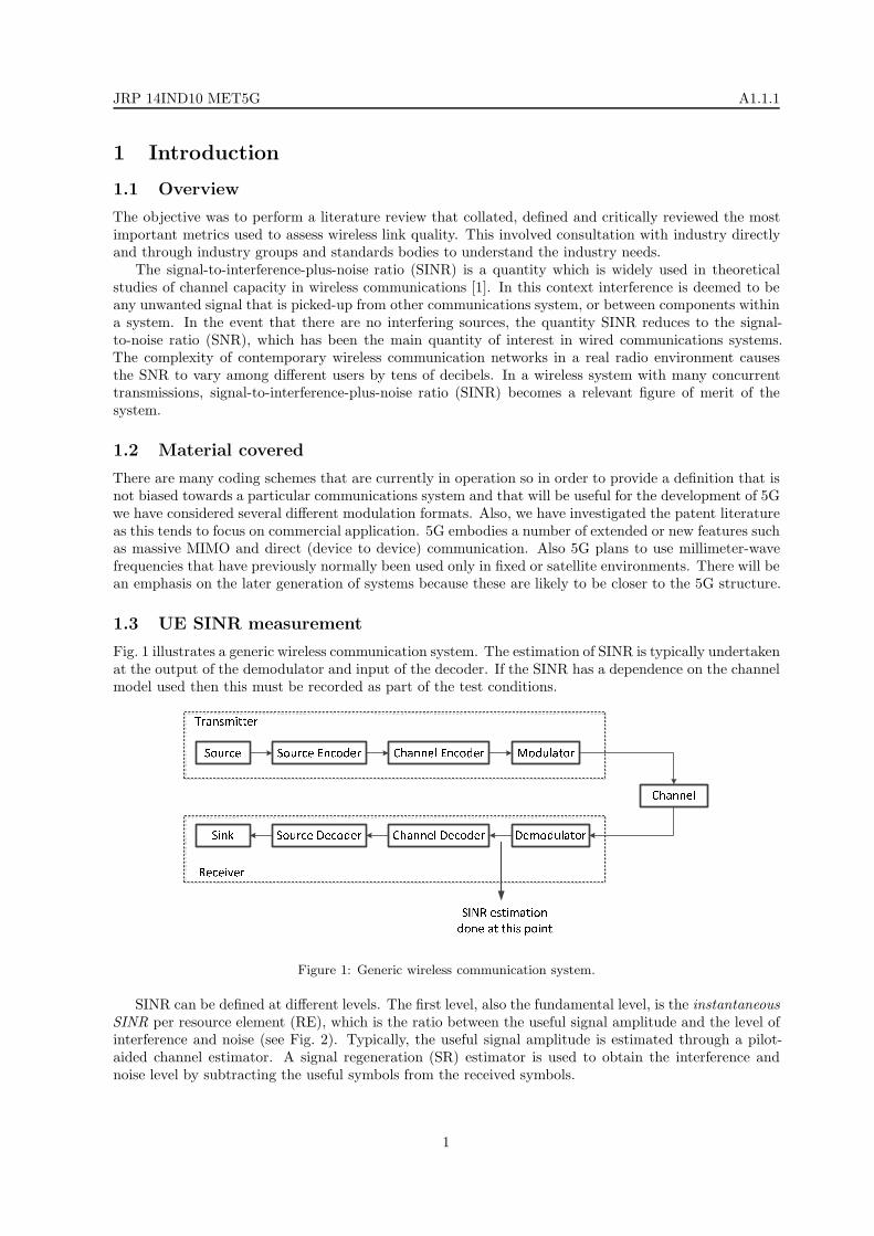
Fig. 1 illustrates a generic wireless communication system. The estimation of SINR is typically undertakenat the output of the demodulator and input of the decoder. If the SINR has a dependence on the channelmodel used then this must be recorded as part of the test conditions.
Figure 1: Generic wireless communication system.
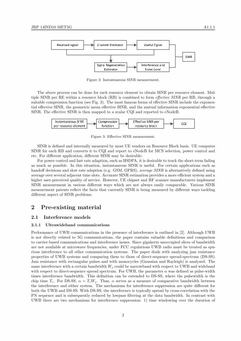
SINR can be defined at different levels. The first level, also the fundamental level, is the instantaneousSINR per resource element (RE), which is the ratio between the useful signal amplitude and the level ofinterference and noise (see Fig. 2). Typically, the useful signal amplitude is estimated through a pilot-aided channel estimator. A signal regeneration (SR) estimator is used to obtain the interference andnoise level by subtracting the useful symbols from the received symbols.
1
JRP 14IND10 MET5G A1.1.1
Figure 2: Instantaneous SINR measurement.
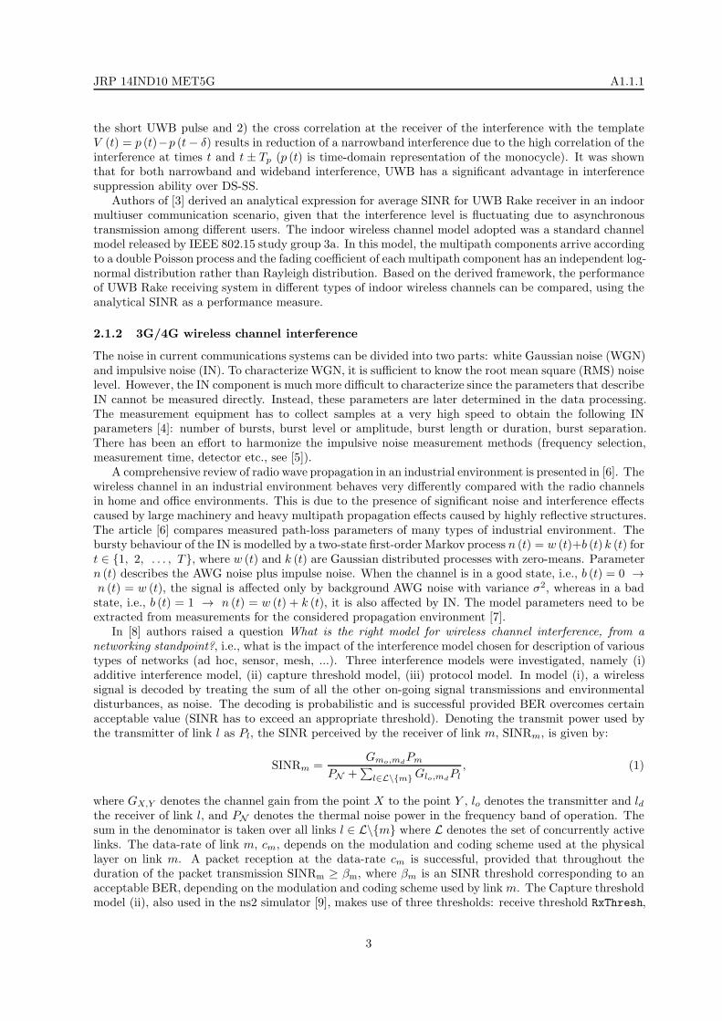
The above process can be done for each resource element to obtain SINR per resource element. Mul-tiple SINR per RE within a resource block (RB) is combined to form effective SINR per RB, through asuitable compression function (see Fig. 3). The most famous forms of effective SINR include the exponen-tial effective SINR, the geometric mean effective SINR, and the mutual information exponential effectiveSINR. The effective SINR is then mapped to a scalar CQI and reported to eNodeB.
Figure 3: Effective SINR measurement.
SINR is defined and internally measured by most UE vendors on Resource Block basis. UE computesSINR for each RB and converts it to CQI and report to eNodeB for MCS selection, power control andetc. For different application, different SINR may be desirable:
For power control and fast rate adaption, such as HSDPA, it is desirable to track the short-term fadingas much as possible. In this situation, instantaneous SINR is useful. For certain applications such ashandoff decisions and slow rate adaption (e.g. GSM, GPRS), average SINR is alternatively defined usingaverage over several adjacent time slots. Accurate SINR estimation provides a more efficient system and ahigher user-perceived quality of service. However, UE chipset and RF scanner manufacturers implementSINR measurement in various different ways which are not always easily comparable. Various SINRmeasurement patents reflect the facts that currently SINR is being measured by different ways tacklingdifferent aspect of SINR problems.
2 Pre-existing material
2.1 Interference models
2.1.1 Ultrawideband communications
Performance of UWB communications in the presence of interference is outlined in [2]. Although UWBis not directly related to 5G communications, the paper contains valuable definitions and comparisonto carrier-based communications and interference issues. Since gigahertz unoccupied slices of bandwidthare not available at microwave frequencies, under FCC regulations UWB radio must be treated as spu-rious interference to all other communication systems. The paper deals with analyzing jam resistanceproperties of UWB systems and comparing them to those of direct-sequence spread-spectrum (DS-SS).Jam resistance with rectangular pulses and with monocycles (Gaussian and Rayleigh) is analyzed. Thesame interference with a certain bandwidth Wj could be narrowband with respect to UWB and widebandwith respect to direct-sequence spread spectrum. For UWB, the parameter α was defined as pulse-widthtimes interference bandwidth. This definition can be extended to DS-SS, where the pulsewidth is thechip time Tc. For DS-SS, α = TcWj . Thus, α serves as a measure of comparative bandwidth betweenthe interference and either system. The mechanisms for interference suppression are quite different forboth the UWB and DS-SS. With DS-SS, the interference is typically spread by cross-correlation with thePN sequence and is subsequently reduced by lowpass filtering at the data bandwidth. In contrast withUWB there are two mechanisms for interference suppression: 1) time windowing over the duration of
2
JRP 14IND10 MET5G A1.1.1
the short UWB pulse and 2) the cross correlation at the receiver of the interference with the templateV (t) = p (t)−p (t− δ) results in reduction of a narrowband interference due to the high correlation of theinterference at times t and t ± Tp (p (t) is time-domain representation of the monocycle). It was shownthat for both narrowband and wideband interference, UWB has a significant advantage in interferencesuppression ability over DS-SS.
Authors of [3] derived an analytical expression for average SINR for UWB Rake receiver in an indoormultiuser communication scenario, given that the interference level is fluctuating due to asynchronoustransmission among different users. The indoor wireless channel model adopted was a standard channelmodel released by IEEE 802.15 study group 3a. In this model, the multipath components arrive accordingto a double Poisson process and the fading coefficient of each multipath component has an independent log-normal distribution rather than Rayleigh distribution. Based on the derived framework, the performanceof UWB Rake receiving system in different types of indoor wireless channels can be compared, using theanalytical SINR as a performance measure.
2.1.2 3G/4G wireless channel interference
The noise in current communications systems can be divided into two parts: white Gaussian noise (WGN)and impulsive noise (IN). To characterize WGN, it is sufficient to know the root mean square (RMS) noiselevel. However, the IN component is much more difficult to characterize since the parameters that describeIN cannot be measured directly. Instead, these parameters are later determined in the data processing.The measurement equipment has to collect samples at a very high speed to obtain the following INparameters [4]: number of bursts, burst level or amplitude, burst length or duration, burst separation.There has been an effort to harmonize the impulsive noise measurement methods (frequency selection,measurement time, detector etc., see [5]).
A comprehensive review of radio wave propagation in an industrial environment is presented in [6]. Thewireless channel in an industrial environment behaves very differently compared with the radio channelsin home and office environments. This is due to the presence of significant noise and interference effectscaused by large machinery and heavy multipath propagation effects caused by highly reflective structures.The article [6] compares measured path-loss parameters of many types of industrial environment. Thebursty behaviour of the IN is modelled by a two-state first-order Markov process n (t) = w (t)+b (t) k (t) fort ∈ 1, 2, . . . , T, where w (t) and k (t) are Gaussian distributed processes with zero-means. Parametern (t) describes the AWG noise plus impulse noise. When the channel is in a good state, i.e., b (t) = 0 →n (t) = w (t), the signal is affected only by background AWG noise with variance σ2, whereas in a badstate, i.e., b (t) = 1 → n (t) = w (t) + k (t), it is also affected by IN. The model parameters need to beextracted from measurements for the considered propagation environment [7].
In [8] authors raised a question What is the right model for wireless channel interference, from anetworking standpoint?, i.e., what is the impact of the interference model chosen for description of varioustypes of networks (ad hoc, sensor, mesh, ...). Three interference models were investigated, namely (i)additive interference model, (ii) capture threshold model, (iii) protocol model. In model (i), a wirelesssignal is decoded by treating the sum of all the other on-going signal transmissions and environmentaldisturbances, as noise. The decoding is probabilistic and is successful provided BER overcomes certainacceptable value (SINR has to exceed an appropriate threshold). Denoting the transmit power used bythe transmitter of link l as Pl, the SINR perceived by the receiver of link m, SINRm, is given by:
SINRm =Gmo,md
Pm
PN +∑
l∈L\m Glo,mdPl
, (1)
where GX,Y denotes the channel gain from the point X to the point Y , lo denotes the transmitter and ldthe receiver of link l, and PN denotes the thermal noise power in the frequency band of operation. Thesum in the denominator is taken over all links l ∈ L\m where L denotes the set of concurrently activelinks. The data-rate of link m, cm, depends on the modulation and coding scheme used at the physicallayer on link m. A packet reception at the data-rate cm is successful, provided that throughout theduration of the packet transmission SINRm ≥ βm, where βm is an SINR threshold corresponding to anacceptable BER, depending on the modulation and coding scheme used by link m. The Capture thresholdmodel (ii), also used in the ns2 simulator [9], makes use of three thresholds: receive threshold RxThresh,
3
JRP 14IND10 MET5G A1.1.1
capture threshold CpThresh (both analogous to the SINR threshold β described above) and carrier-sensing threshold CsThresh. A packet reception on a link m at the data-rate cm is successful, providedthat during the packet transmission PmGmo,md
≥ RxThreshm and PmGmo,md/PlGlo,md
≥ CpThreshm∀l ∈ L\m. Hence, the interference is accounted for only one interferer at a time. For carrier-sensing, anode at Y will sense the channel busy if PlGlo,Y ≥ CsThreshm for some active l, where CsThresh is thecarrier-sensing threshold analogous to βcs from model (i), i.e.
∑
l∈L
PlGlo,Y + PN ≥ βcs. (2)
According to the protocol model (iii) in [8], a packet transmission on link m is successful, provided that foreach link l ∈ L\m we have |lo −md| ≥ (1 + ∆) |mo −md| and |mo −md| ≤ Rc, where ∆ is a positiveparameter and Rc stands for communication range. The capture threshold model is equivalent to theprotocol model under isotropic path loss. The interference range model (iv) assumes fixed ranges forcommunication and interference. According to the this model, a packet reception on link m is successful,provided that for each link l ∈ L\m we have |lo −md| ≥ RI and |mo −md| ≤ Rc, where RI standsfor interference range and Rc stands for communication range. The interference range model requiresthe interferer-receiver separation to be greater than a fixed quantity, the interference range, rather thanproportional to the transmitter-receiver separation as in the protocol model (iii). Further details andthree case studies are given in [8]. An important conclusion is that different physical layer models canlead to different results and applicability of particular interference models.
It is also essential to study the statistics of SINR. The direct approach to compute the average of SINRand its higher moments requires knowledge of the probability density function of SINR, which is difficultto obtain in general. Authors of [1] discuss the problem of finding E[SINRn] is related to the problem offinding the nth negative moments of positive random variables. New exact expressions for the first andsecond-order averages E[SINRn], n = 1, 2, . . ., and E[SINR1SINR2], where SINR1 and SINR2 denotethe SINR at two different instances (different sampling times, frequencies or geometrical locations). Thepractical calculation uses tables of Mellin transforms and special functions. SINR analysis of correlatedexponential and log-normal random variables is discussed, together with numerical examples for a CDMAcell with imperfect power control. It was shown that SINR decreases when the useful signal becomescorrelated with the interference signals. On the other hand, when the useful signal becomes independentof the interference signals then a positive correlation among the interference signals results in an increasein the average SINR. That is, correlated interfering signals are more harmful than the correspondingindependent signals.
Early SINR approaches can be found in CDMA networks [10], where interference and power control infading radio channels was studied. In CDMA networks each user can transmit a message simultaneouslyover the same radio bandwidth using specific pseudo-random code sequences. Systems which rely onimproved performance from coding and interleaving, however, may require more rapidly acting powercontrol (it is assumed that the power control is performed at a higher rate than the rate of multipathfading). Two different feedback power control algorithms were taken into account: fixed step powercontrol and average power control. A simulation was performed with many concurrent users in a squarearea and the average interference was observed. The model of power control is idealised, i.e., it assumesa perfect absolute power measurement at each base station. For this reason the work was extendedin [11], where a power control based on SINR was studied. In general, if the short-term variation ofSINR is negligible compared to that of the desired signal, there is no performance distinction betweenpower control using absolute signal measurement and that based on the measurement of SINR. Whena system with SINR-based power control approaches its capacity limit, all the users must increase theirpower to minimize the effect of thermal noise. A power change of any user will affect the interferenceseen by all other users and create some degree of positive feedback to the individual control processes.The performance of a system using SIR-based power control depends greatly on how the power controlthreshold of each user is set [11].
Stuedi and Alonso [12] studied capacity of wireless multi-hop networks under various interferencesand radio propagation models, including the physical interference model and log-normal shadowing ra-dio propagation (signal strength perceived by a certain node not only depends on the distance betweentransmitter and receiver, but also includes some random factor). The protocol and the physical inter-
4
JRP 14IND10 MET5G A1.1.1
ference model were taken into account. In the protocol model, a transmission from a node u is said tobe received successfully by another node v if no node w closer to the destination node is transmittingsimultaneously. However, in practice, nodes outside the interference range of a receiver might still causeenough cumulated interference to prevent the receiver from decoding a message from a given sender. Thisbehavior is captured by the physical model, where a communication between nodes u and v is successfulif the SINR at v (the receiver) is above a certain threshold. Network capacity analysis was explainedusing a conflict graph (transmissions that cannot be scheduled simultaneously). Authors conclude thatthere was a significant performance gap between capacity under the physical interference model and ca-pacity under the most commonly used protocol model. It was shown that taking into account log-normalradio propagation creates more interference but also decreases the total amount of transmission to bescheduled.
An efficient inter-site interference model for 4G wireless networks was introduced in [13]. The conven-tional manner in simulating complex topologies (e.g., 4G wireless networks) is to implement a two-tiernetwork (i.e. 19 sites, 57 hexagonal sectors) and subsequently evaluate the performance of user equipmentUE from the inner tier. Alternatively, only one tier is simulated and the central site (i.e. the three centralsectors) is accounted for the evaluation of performance while the 6 remaining sites are again discarded.The work was motivated by the need for an evaluation platform that provides proper inter-site interfer-ence across the region of interest without wasting computational power. The method [13] allows for usewith limited resources in contrast to traditional wrap-around techniques with toroid-shaped topologies.The duplication of virtual eNBs is involved at indicated positions exclusively during the interference cal-culation. All features of the eNBs are replicated, avoiding additional overheads on the complexity of thesystem.
Conventional investigations on the capacity of a secondary link in spectrum sharing environmentshave assumed that a secondary user knows perfect channel information between the secondary transmit-ter and primary receiver. However, this channel information may be outdated at the secondary userbecause of the time-varying properties or feedback latency from the primary user. If the secondary userallocates transmission power using this outdated channel information, the interference power to the pri-mary receiver will not satisfy the predetermined interference constraint. Kim et al. [14] investigated theperformance of secondary user while considering interference power constraints, the outdated CSI, andthe interference from the primary transmitter (PTx). In the spectrum sharing model (primary and sec-ondary receiver and transmitter, referred here to as PRx, PTx, SRx and STx, respectively), secondaryuser can share the primary user’s spectrum, as long as the amount of interference inflicted on the PRxis within a predetermined constraint. Since the secondary user shares the spectrum of the primary useronly within the predetermined interference power constraint, the PRx receives interference from the STxwithin the predetermined interference power. Furthermore, the SRx also receives interference from thePTx. A point-to-point flat Rayleigh fading channel is assumed, h0, h1, h2 denote instantaneous complexGaussian channel values from the STx to the PRx and from the STx to the SRx, and from the PTxto the SRx, respectively. The instantaneous channel gains are then denoted by g0 = |h0|2, g1 = |h1|2,g2 = |h2|2, respectively. The CSI on h0 provided to the STx is outdated due to the time-varying natureof the wireless link. This imperfect CSI can be described by a correlation model, in which
h0 = ρh0 + h0
√1− ρ2, (3)
where h0 is the outdated channel information which the secondary user knows, and h0 is a complexGaussian random variable with zero mean and unit variance, and is uncorrelated with h0. The correlationcoefficient ρ is a constant which determines the average quality of the channel estimate over all channelstates of h0. The ergodic capacity of the secondary user under the average received-power constraintis derived solving rather complicated optimization problems, for details see [14]. Only lower and upperbound of the capacity could be derived in a closed-form. The SINR in this case can be written as
SINR =g1P (ρ, g0, g1)
N0B + g2PPTx, (4)
where PPTx is the transmission power at the PTx. Both analytical and simulated results demonstratedthat the ergodic capacity of the secondary user under the average received-power constraint is more robustto the outdated channel environment than the peak received-power constraint.
5
JRP 14IND10 MET5G A1.1.1
In contemporary 4G LTE networks, SINR is not defined by 3GPP but is currently been definedas a “Channel Quality Indicator” (CQI), which reports to the network [15]. Also, there are detailedsimulation studies of the loss of throughput for various victim-aggressor scenarios [16]. Reference SignalReceived Power (RSRP) and Reference Signal Received Quality (RSRQ) also would apply [17], whichwould be determined by a measured SINR. Traditionally, a target link quality is characterized by atolerable bit error rate that, in turn, maps to a required SINR [18]. The SINR is an efficient criterion forseveral radio resource management algorithms such as power control, data rate adaptation algorithmsand cell handoff. There exist various techniques for SINR estimation for various scenarios and wirelessstandards (e.g., cellular TDMA [19], CDMA [20], fast rate adaptation systems such as 3G HSDPA [18],MIMO systems [21], WLAN [22]). Classical methods of communication theory are generally insufficientto analyze these new types of networks for the following reasons [23]:
• The performance-limiting metric is the SINR rather than the SNR.
• The interference is a function of the network geometry on which the path loss and the fadingcharacteristics are dependent upon.
• The amount of uncertainty present in large wireless networks far exceeds the one present in point-to-point systems: it is impossible for each node to know or predict the locations and channels of allbut perhaps a few other nodes.
Two main tools have recently proved most helpful in circumventing the above difficulties: stochasticgeometry and random geometric graphs (see the [23] and references therein, or the newer work [24]).Stochastic geometry allows to study the average behavior over many spatial realizations of a networkwhose nodes are placed according to some probability distribution. Random geometric graphs capturethe distance-dependence and randomness in the connectivity of the nodes. Perhaps the largest impacthas been in the area of ad hoc networks, which are fully distributed and in which all participating nodes- both transmitters and receivers - are randomly located. In such networks, it is impossible even withunlimited overhead to control the SINRs of all users, due to the coupling of interference: if one user raisesits power, it causes an interference increase to all other communicating pairs. In this case, characterizingthe (stochastic) geometry of the network is of utmost importance since it is the first-order determinantof the SINR.
In 4G LTE networks [25], the following metrics are used: RSRP is the most basic of the physicallayer measurements. It is an expression of the linear average of the downlink Reference Signals, in watts,across the channel bandwidth. Providing the UE with knowledge of absolute RSRP, is essential, since itprovides information about the strength of cells from which path loss can be calculated, and afterwardsused in optimization algorithms. However, the measure of RSRP give no indication of the signal quality.The RSSI represents the entire recieved power, which is radiated onto the UE, including wanted powerfrom the serving cell, as well as all other co-channel power and noise. Given RSRP and RSSI, the RSRQ isan important measure, since it is defined as a ratio between RSRP and RSSI. A mathematical expressionof RSRQ can be seen in equation
RSRQ = #RBdB +RSRP
RSSI, (5)
where #RB (resource block) is the physical amount of bandwidth which can be scheduled on the eNB andare allocated to the UE. The Ressource Block is the smallest unit, that can be scheduled. It physicallyoccupies 180 kHz in frequency, and 0.5 ms in time. Thus for a channel bandwidth of 10 MHz (includingguardspaces, etc.), a maximum of 50 RBs can be alotted. For the full channel bandwidth of 20 MHz,there are 100 RBs available.
In IEEE 802.11 wireless LAN it has been shown that simple theoretical models to predict the impactof interference in wireless networks, e.g. using simple path loss models, have very limited accuracy inrealistic and relatively complex deployment scenarios (many environment and hardware-specific factorsmust be considered and empirically testing every group of links is not practical: a network with n nodescan have O(n2) links, and even if we consider only pairwise interference, we may have to potentially testO(n4) pairs, see, e.g., [26]). Consequently, there has been a trend towards measurement-based approaches.A comparison of three different measurement-based models is performed in [22], namely the RSS profile
6
JRP 14IND10 MET5G A1.1.1
method, the SNR profile method and the SINR profile method. The authors conclude that across allevaluations, the results show that an interference model that uses an SINR profile consistently performsthe best in predicting the PDR performance of a wireless link.
1. RSS profile methodIn this model, measurements of pairs PDR, RSS between pairs of nodes are performed by havingeach node taking turns to broadcast packets, and every other node measuring the packet PDR andcorresponding RSS. The PDR value is defined as the ratio of the number of packets successfullyreceived to the number of packets sent, while the RSS values are retrieved from the captured packettraces at the receiving node [22]. At every node, the set of these tuples is plotted to obtain an “RSSprofile” for that node, which can be interpreted as the probability of successful packet reception asa function of the measured RSS. The authors conclude that the RSS profile is dependent on theenvironment in which it is constructed.
2. SNR profile methodIn addition to measurements of the pairs PDR, RSS between pairs of nodes, measurements ofthe noise floor at each node are also taken [27]. The SNR value is then computed as the ratio ofthe RSS value to the NF value. At every node, the set of the pairs PDR, SNR is then plottedto obtain an “SNR profile” for that node. In order to use the SNR profile to predict the PDRperformance of a wireless link in the presence of interferers, one needs to first know the RSS of theindividual interferers. This can be easily obtained from the initial measurements of RSS betweenpairs of nodes, during the SNR profile construction phase. The RSS values (in mW) correspondingto the concurrent sender and interferers are then used as input into the equation [22]
SINR =Rsr∑
i Rtir +NF, (6)
where Rsr is the mean RSS of sender s as measured at receiver r during the initial SNR profileconstruction phase, Rtir is the mean RSS of interferer ti as measured at receiver r during the initialSNR profile construction phase and NF is the mean noise floor at receiver r. The computed SINRvalue is then used to lookup the SNR profile to determine the corresponding PDR value.
3. SINR profile methodIn [28], a slightly different measurement approach is proposed to construct SINR profile. First,measurements of RSS between pairs of nodes are performed, similar to [27]. Next, concurrenttransmissions from a sender and an interferer are carried out, and the receiver records the numberof packets it receives correctly from the sender. This is then used to compute the PDR of thesender-receiver link, in the presence of the interferer. The corresponding SINR value is computedin (6), by using the values of the sender’s and the interferer’s RSS values, and the noise floor NFat the receiver. Different pairs of sender, interferer nodes are used to generate many pairs of PDR,SINR, which are then used to construct the SINR profile.
2.1.3 Pre-5G wireless channel interference
The ns2 network simulator [9] was further improved and now version ns3 [29] also contains a mmWavemodule and simple channel and interference models for future 5G systems [30]. As for interference, amodel suitable for LTE networks was adopted (Mutual Information Based Effective SINR (MIESM)). Thereceiver computes the error probability for each transport block (TB) and determines whether the packetcan be decoded or not. After the reception of the data packets, the physical (PHY) layer calculates theSINR of the received signal taking into account the MIMO beamforming gains. The physical layer at theuser device maps the calculated SINR into a CQI, which is fed-back to the base station for the resourceallocation. The TB can be composed of multiple codeblocks (CB) and its size depends on the channelcapacity. The block error probability (BLER) of each CB depends on its size and associated modulationand coding schemes (MCS):
CBLER,i (γi) =1
2
[1− erf
(γi − bCSIZE,MCS√
2cCSIZE,MCS
)], (7)
7
JRP 14IND10 MET5G A1.1.1
where γi is the mean mutual information per coded bit of the codeblock i, bCSIZE,MCS and cCSIZE,MCS
corresponds to the mean and standard deviation of the Gaussian cumulative distribution, respectively.The TB block error rate can then be computed as:
TBLER = 1−C∏
i=1
(1− CBLER,i (γi)). (8)
In case of failure, the PHY layer does not forward the incoming packet to the upper layers and, at thesame time, triggers a retransmission process (this can be a TCP retransmission, or an hybrid automaticrepeat request (HARQ)). The interference computation is still relevant in future 5G networks workingin millimetre wave bands, despite the directionality of multiantenna propagation. In fact, there mightbe some special spatial cases where interference is non-negligible [30]. An interference computationscheme was proposed which takes into account the beamforming directions associated with each link.The beamforming gain from transmitter i to receiver j is given as
G(t, f)ij =∣∣∣w∗
rxijH(t, f)ijwtxij
∣∣∣2
, (9)
where H(t, f)ij is the channel matrix of ijth link, wtxijis the beamforming vector of transmitter i when
transmitting to receiver j andwrxijthe beamforming vector of receiver j, when receiving from transmitter
i. For instance, if we want to calculate interference between user equipment UE1 and base station BS1
(with presence of interfering base station BS2 and user equipment UE2), one can write
SINR11 =
PTx,11
PL11G11
PTx,22
PL21G21 +BW ·N0
, (10)
where PTx,11 is the transmit power of BS1, PL11 is the pathloss between BS1 and UE1 and BW ·N0 isthe thermal noise.
Venugopal et al. [31, 32] characterized the performance of millimeter-wave wearable communicationnetworks, such as IEEE 802.11ad (WiGig), Wireless HD and device-to-device operating modes proposedfor millimetre wave-based 5G cellular systems. A limited region and a finite number of interferers atfixed locations was considered and an approach for calculating coverage and rate in such a network wasdeveloped. In crowded environments such as train cars or airline cabins, human bodies are a main andsignificant source of blockage of millimetre wave frequencies. Nakagami (Gamma) fading was used insimulations. From the locations of the transmitters and blockages, a CCDF of the SINR was found. Thenetwork topology considered in [31] is a finite-sized 2D network region A with a reference transmitter-receiver pair and K potentially interfering transmitters. The transmitters and their locations are denotedby Xi, i = 0, 1, . . ., K, where X0 is the reference transmitter location. The reference receiver is locatedat the origin and represents Xi as a complex number Xi = Rie
jφi , where Ri = |Xi| is the distance tothe ith transmitter and φi = ∠Xi is the angle to Xi from the reference receiver. The CCDF is calculatedas follows: a discrete random variable Ii for i = 1, . . . ,K is defined, representing the relative powerradiated by Xi in the direction of the reference receiver. With probability (1− pt), Xi does not transmitand hence Ii = 0. Otherwise, the relative power will depend on whether or not the random orientation ofXi’s antenna is such that the reference receiver is within the main-lobe. An uniform orientation of Xi’santenna is assumed and thus the probability that the reference receiver is within its main-lobe is θt
2π . Itfollows that
Ii =
0 with probability (1− pt)
Gt with probability pt(θt2π
)
gt with probability pt(1− θt
2π
) , (11)
where Gt is the transmitter main-lobe, gt is the receiver main-lobe, θt is the beamwidth of the antennamain-lobe at the transmitter. The normalized power gain from Xi is then defined as
Ωi =
Pi
P0GrR
−αii if − θr
2 ≤ φi − φ0 ≤ θr2
Pi
P0grR
−αii otherwise
. (12)
8
JRP 14IND10 MET5G A1.1.1
The SINR is then calculated as
SINR =h0Ω0
σ2 +K∑i=1
IihiΩi
, (13)
where Ω0 = GrR−α0
0 is the normalized power gain from the reference transmitter, as the referencetransmitter is always assumed to be within the main beam of the reference receiver. Authors of [31, 32]observed a significant improvement in coverage probability with larger antenna arrays, and concludedthat having more transmit antennas is more advantageous than having more receive antennas.
Numerous studies are referenced in [33] on wireless interference models, capacity analysis of multi-antenna cellular networks and cooperative transmission in wireless communications. As authors of [33]claim, however, in all the referenced capacity studies, only simple scenarios, such as a single cell withfinite interfering transmitters, were considered and the underlying channel models were limited to simpleflat Rayleigh fading channels. They derived the exact downlink average capacity of multi-cell MIMOcellular network with co-channel interference, and the analytical closed-form normalized downlink averagecapacity for cell-edge users in a multi-cell MISO cooperative cellular network with co-channel interferencewas derived and analyzed numerically. Their analysis indicates that the cooperative transmission canefficiently enhance the capacity performance, especially in scenarios with high densities of interferingBSs.
A mobility-aware uplink interference model for 5G heterogeneous networks (a mix of macro cellsand small cells) is presented in [34]. Based on the Levy flight moving model, an interference model isproposed to characterize the uplink interference from macro cell users to small cell users. The totaluplink interference is characterized by its moment generating function, for both closed subscriber groupand open subscriber group femto cells. In addition, the proposed interference model is a function of basicstep length, which is a key velocity parameter of Levy flights.
Traditional network models such as the rectangular or hexagonal grid are becoming increasinglyobsolete. This is mainly caused by the fact that these approaches do not allow to account for a massiveirregular deployment of base stations. A new circular interference model that aggregates given interferertopologies to power profiles along circles is introduced in [35]. A mapping procedure that preservesthe aggregate interference statistics at arbitrary user locations within the associated cell with a certaindesired accuracy is presented. At the same time, the method identifies the number of nodes in a giveninterferer topology that principally determine the shape of the interference distribution. The approachallows decomposing the distribution of the aggregate interference into the contributions of the individualinterferers. This enabled to accurately model the interference statistics of fully random, heterogeneoustopologies with 10 000 and more base stations by some ten nodes in the entire associated cell. Moreover,the proposed method enables accurate prediction of the corresponding SIR and rate statistics.
A statistical inter-cell interference model for downlink cellular OFDMA networks under log-normalshadowing and multipath Rayleigh fading was introduced in [36]. Most of the previous results on theperformance evaluation of cellular OFDMA networks have been based on the Gaussian approximation ofthe inter-cell interference. Accurately taking into account the statistics of the interference could drasti-cally improve the decoded performance. The network model considered in the paper is a homogeneous,synchronous, downlink cellular OFDMA network, one QAM modulated symbol per mobile is transmittedin one of the available subcarriers in each OFDM symbol where the subcarriers are chosen randomlyfrom the available subcarriers. Taking FFT of the discrete-time complex baseband equivalent receivedsamples for a duration of an OFDM symbol, one can derive the final decision variable for each subcarrier,which represents the effects of ICI and the AWGN. Then the PDF of the decision variable is derived andthe validity is verified using a Monte Carlo simulation. The maximum-likelihood decoder based on thederived PDF significantly outperforms the traditional decoder optimized for the AWGN channel.
Improving the network throughput (how fast the network may deliver data) and improving the net-work lifetime (how long the network may last) are two important design objectives for multihop wirelessnetworks, which appear to be in conflict with each other and a trade-off must be identified. Authorsof [37] consider wireless networks that are operated by scheduling link transmissions to be conflict-free,as opposed to a random access MAC protocol (supported, e.g., by IEEE 802.16 and LTE cellular net-works). A realistic interference model is used based on the SINR for modeling the conflicts to avoidwhen scheduling the wireless links. It is assumed that the interference to a certain link is the cumulative
9
JRP 14IND10 MET5G A1.1.1
interference from the multiple links that are activated during the same period of time. Three optimiza-tion problems are formulated: (i) to maximize the network lifetime while achieving the max-min networkthroughput; (ii) to maximize the network throughput while achieving a pre-specified network lifetime;(iii) to maximize the network lifetime while achieving a fraction of the max-min throughput. Flow routesand link schedules are jointly selected to achieve the desired objective. The channel gain is modelled asisotropic path-loss. The feasibility of a wireless link is based on whether a BER less than a tolerable max-imum can be achieved on the link. This BER requirement translates into a minimum SINR requirementcorresponding to a SINR threshold β (z), depending on modulation scheme z.
2.2 Prior art protected by patent
2.2.1 Jeske, 2003, US20030016740
Jeske [38] proposes SINR estimation for BPSK, but not limited to BPSK. The method claims to improvethe square mean error of the conventional SMV estimator by scaling and translation. Noise and inter-ference are modelled together as additive white Gaussian noise (AWGN). The channel attenuation andphase shift is assumed to be fixed over a timeslot. The square mean error of the estimator is further im-proved by forming a composite SINR using both the pilot and data symbols: a pilot symbol based SINRestimate and a data symbol based SINR estimate are weighted and combined to generate a compositeSINR estimate having a reduced mean square error as compared to either of the individual estimators.This is because the pilot symbols have the advantage of being known at the receiver but are relativelyfewer in number. Data symbols are more plentiful than pilot symbols but they are unknown at thereceiver. The combination of both thus improves the accuracy.
2.2.2 Olszewski, 2004, US20030223354
Olszewski [39] proposes Fast-Fourier transform (FFT)-based SINR measurements methods for wirelesscommunications systems which employ OFDM for multicarrier data transmission. Given a known trans-mitted time-domain OFDM frame preamble, and the corresponding channel and interference-plus-noise(IPN) corrupted received time-domain frame preamble, the method first computes the power spectraldensities of the received signal of interest and of a received unwanted interference-plus-noise signal. TheFFT-computed power spectral densities are then used to compute average received signal and receivedIPN power measurements for specified individual or groupings of OFDM subchannel signals. The powermeasurements are then frame-averaged using a recursive exponential smoothing method. The frame-averaged signal and IPN power measurements are then used to form quantized measurements of SINRfor the specified OFDM subchannel signals of the received frame.
2.2.3 Des Noes, 2010, Patent US7751468
Des Noes [40] proposes SINR estimation for OFDM-CDMA. The invention takes account of the effectof synchronization errors, independent of the value of the codes. The synchronization errors consideredincludes the offset between carrier frequencies of the transmitter and the receiver and the offset betweenthe transmitter and receiver sampling clocks. The SINR can be estimated for an OFDM-CDMA systemusing a 2-dimensional spread in the time and frequency domains, or for aa OFDM-CDMA system usinga 2-dimensional spread with a channel varying in time. If the codes are orthogonal, the SINR may beestimated taking account of the orthogonality of the codes.
2.2.4 Kangas, 2011, Patent US7986919
Kangas [41] proposes a recursive method of calculating an inverse impairments matrix used to generatean SINR estimate, which in turn is used to generate a CQI estimate. The recursive inverse impairmentsmatrix calculation avoids the need to perform a computationally intensive matrix inversion, allowing forfaster CQI estimate generation and consuming less power. Channel conditions from each transmit antennato each receive antenna are estimated and a matrix of estimated channel noise covariance is generated. Aninitial inverse impairment matrix for a given pilot position is calculated based on the channel conditionsand the channel noise covariance. An inverse impairment matrix is recursively calculating for the pilot
10
JRP 14IND10 MET5G A1.1.1
position by recursively summing the noise and inter-stream interference, beginning with the initial inverseimpairment matrix. An SINR is then calculated based on the recursively calculated inverse impairmentmatrix.
2.2.5 Grant, 2011, Patent US20110026566
Grant [42] also discussed the problem with employing the conventional CPICH based SINR estimationapproach for MIMO. First is the additional interference created by the reuse of spreading codes onthe HS-DSCH (data) channel when in dual-stream mode. Such so-called code-reuse interference doesnot exist on the CPICH (pilot) channel since the pilots transmitted on each antenna are orthogonal.Hence use of the conventional CPICH-based SINR estimation approach yields an over-estimate of datachannel quality leading to excessively high block error rates and thus significantly reduced throughput.In addition, precoding is used on the HS-DSCH whereas no precoding is used on the CPICH. Precodingalso affects SINR, hence SINR values calculated using the conventional CPICH-based SINR estimationapproach yields an even more inaccurate representation of the data channel quality since precoding isnot employed on the pilot channel upon which SINR is solely derived. To address these issues, a methodis proposed which enables pilot-based SINR estimation for MIMO system through a combination ofparametric and non-parametric approaches.
2.2.6 Semenov, 2012, Patent US20120201285A1
Semenov [43] proposes an apparatus and method for SINR estimation for HSDPA MIMO receiver. TheSINR evaluation is based on both the pre-coded data stream and pilot signal. The received data streamis first processed through by an equalizer with a set of equalizer filter coefficients. The inter-stream inter-ference is evaluated based on the post equaliser channel coefficients and the set of weighting coefficientsfor the pre-coded stream.
2.2.7 Sesia, 2012, Patent US20120310573
Sesia [44] proposes a method based on the estimation done only on a selected number of samples. Inparticular, only the most reliable samples are selected for the SINR estimation. It claims that throughidentification of a group suppresses the problem of miss identification of a single sample and by withdrawof samples subjected to intersymbol interference enables a reduction of the contribution of interferencein noise calculation which overestimates the SINR calculation.
2.2.8 Zhang, 2012, Patent EP2 398 269A1
Zhang [45] commented that the conventional methods measure the SINR based on SRS (Sounding Ref-erence signal) or DMRS (Demodulation Reference Signal). The problem with these method is that theSRS or DMRS sent by the UE are distributed randomly relative to the channel resource of the UE to beestimated, that is, the relative position of the channel resource occupied by the SRS or DMRS sent bythe UE and the channel resource of the UE to be estimated is not fixed. As a result, obtaining the SINRby only using the SRS or DMRS, the accuracy of the SINR estimates for different channel resources to beestimated is not stable. The method proposed is to evaluate the channel correlation. The more accurateSINR is calculated based on SRS-based SINR, DMRS-based SINR and channel correlation. The chan-nel correlation between the channel resource occupied by the last SRS sent by the UE and the channelresource is determined by:
• time offset sensitivity of a wireless channel
• time offset between the channel resource occupied by SRS and user data
• frequency offset sensitivity of a wireless channel
• frequency offset between the channel resource occupied by SRS and user data
11
JRP 14IND10 MET5G A1.1.1
2.2.9 Jia, 2013, Patent US8416881
Jia [46] proposes a method for determining an effective SINR associated with transmission of modulationsymbols with different modulation schemes (e.g., QPSK, 16QAM, 64QAM) in OFDM systems. Eachsubcarrier of a channel may have a different SINR. The method proposed in the patent maps the instan-taneous SINR of multiple subcarriers into an effective channel SINR (given particular channel state). Thetransmissions can be separate transmissions that are combined together, such as in A-HARQ retransmis-sions or FEC blocks, or it can be a single transmission of a data block using different modulation schemes,such as spatial multiplexing in a MIMO transmission.
2.2.10 Semenov, 2013, Patent US008553803B2
In another patent [47] Semenov pointed out that the application of MIMO systems to WCDMA HSDPAsystems is problematic with regards to calculating or estimating the SINR. In particular it is not practicalto use the same methods used in conventional HSDPA approaches to estimate the SINR for D-TxAAHSDPA modes of operation. In conventional WCDMA implementations the SINR is calculated using pilotsymbols with a known pattern and signal strength and measuring the difference between the received andexpected symbols. In a MIMO implementation data is typically split into at least two streams and thedata symbols are pre-coded with the help of pre-coding weights whilst the pilot symbols are transmittedon a separate channel, the Common Pilot Channel (CPICH), without pre-coding. As the CPICH pilotsymbols are not pre-coded, it is not possible to use the conventional SINR estimation methods. Anapparatus is thus proposed which generates fake pre-pilot signals by applying the beamforming weightingcoefficients so as to enable the decoder to use this knowledge to calculate the SINR for MIMO.
2.2.11 Bontu, 2014, Patent US20140233408
Bontu [48] proposes a method and system for formulating an SINR metric for cells using only the existingRSRP and RSRQ measurements. In certain technologies, such as OFDM, a communication channel isimplemented through multiple sub-carriers. Each sub-carrier may have different modulation order, anddifferent SINR at a particular instant in time.
2.2.12 Mizrahi, 2014, Patent US008630335
Mizrahi [49] recognised the limitation of conventional SINR measurement using a Mean Square Error(MSE) estimator. An MSE estimator takes a difference between a received signal and symbols decodedfrom the received signal, and calculates the mean square error. But such an estimator is only efficientwhen transmitted symbols are discrete and the receiver is phase locked. In the situation of low SINR,and the receiver is not phase locked, the MSE method cannot estimate SNR accurately, because thedecisions are not reliable. Therefore, the author proposed non-data aided (NDA) estimator for low SINRmeasurement. An NDA estimator is an estimator that estimates SINR without knowledge of the actualtransmitted data.
2.3 MIMO Systems
MIMO systems involve the transmission of several modes at the same frequency, whereby there is self ainterference between the modes that are not fully orthogonal in practice, but where two or more users areoperating in the same cell, each transmission mode is vulnerable to interference from the transmissionmodes of other users. The same vulnerability is also at risk where a mobile device is on a cell edge and mayreceive interference from a base station of a neighboring cell transmitting the modes. In [50], simultaneousreal time 4x4 MIMO measurements from three base stations to the same mobile were analysed at 5 GHzfor the cell edge scenario simultaneously in real time. Such measurements could then determine the realtime scale of interference from neighbouring cells due to lack of orthogonality between their respectiveeigenvectors. Signal to interference ratio was determined by analysis of the singular values and singularvectors computed by the singular value decomposition (SVD) from the wanted channel in the cell withinwhich the mobile was positioned and the interfering channels from neighboring cells. Other analysis wascarried out in [51] by analyzing the interference between two mobile users from the same base station.
12
JRP 14IND10 MET5G A1.1.1
Computation of the SIR is first defined by taking the power of the first eigenmode, equivalent to the firsteigenvalue (or square of the singular value of a wanted time variant channel in base station A, HA (t)defined as follows:
s21A (t) =∣∣uH
1A (t)HA (t)v1A (t)∣∣2, (14)
where the singular vectors of the first eigenmode channel with the highest diversity order, u1A and v1Aare determined by SVD. The term H is the Hermitian transpose. At a cell edge to cell B, there will bean interfering channel in real time, HA (t) which will also have corresponding singular vectors, u1B andv1B for a mobile in use in that cell. The base station will be transmitting modes with singular vector v1Bbut the mobile in cell A will receive the modes from cell B non orthogonally and without diversity whenit is set with vector u1A yielding an interference term to define the SIR as follows:
SIR =s21A (t)
∣∣uH1A (t)HB (t)v1B (t)
∣∣2 . (15)
This therefore shows a ratio of the transmitted power in cell A of the highest eigenmode with diversityto the interference from cell B on that one eigenmode. In MIMO there are at least two eigenmodes andso it is possible that the SIR can be defined in a similar manner for any eigenmode n as follows:
SIR =s2nA (t)
∣∣uHnA (t)HB (t)vnB (t)
∣∣2 . (16)
Similarly the SIR can be analysed this way for comparing interference between two mobiles A and B. Thesedefinitions of SIR will give a theoretical limit of SIR available in a fully orthogonal MIMO transmission.Other beamforming methods will not yield a fully orthogonal transmission of modes which will have aself interference and thus the SIR will be lower in practice than the SIR evaluated by SVD and thereforethe SIR achieved is dependent on the beamforming scheme used.
Zhang [52] analysed the SINR impairment due to frequency offset and channel estimation errorsin MIMO-OFDM. The channel is assumed to be frequency-selective Rayleigh fading. It shows thatthe interference can be decomposed into two independent components: inter-carrier interference andinterference contributed by other transmit antennas. Based on the analysis of the demodulated signaland interference, SINR for each receive antenna is derived. The SINR for MIMO OFDM systems withequal gain combining (EGC) and maximal ratio combining (MRC) are also derived.
The evaluation of SINR for MIMO system can be different when different detector is employed. Whenthe linear minimum mean-squared error (LMMSE) detector is used, the SINR can be explicitly computedfor each spatial stream using channel estimates. However, this is not the case for the optimal maximumlikelihood (MLD) detector which is gaining growing interest in research and practice. Abe [53] studies thecomputation of SINR per spatial stream when MLD is employed in MIMO-OFDM spatial multiplexingsystems.
The MIMO signal processing usually employs complicated signal processing schemes, e.g. eigenmodebeamforming. Parallel transmission as a means of simplifying these schemes was studied by severalauthors. In parallel transmission, however, the channel capacity is greatly degraded due to the interferencefrom adjacent antenna elements. Authors of [54] proposed a simple method for canceling interferenceby using antenna directivities. Following system model is considered: two antenna arrays are facingeach other, the transmitter has Nt antennas and the receiver has Nr antennas. It is considered that thepropagation environment is static and free space. All antennas have vertical polarization for simplicity.The received signal y (t) ∈ CNr×1 can be expressed as y (t) = H0s (t) + n (t), where H0 ∈ CNr×Nt is achannel matrix and s (t) ∈ CN−T×1 is a transmit signal vector and n (t) ∈ CNr×1 is a noise vector withall components having identical variance. For short-range transmission, the environment is static andthe channel response depends on the gain and the phase rotation between transmit and receive antennas.Thus, the component of H0, which is the channel response from the j-th transmit antenna to the i-threceive antenna, is expressed as hi,j =
λ0
4πdi,jexp (−jαi,j), where λ0 is the wavelength, di,j is the distance
and αi,j is the phase rotation between the j-th transmit and the i-th receive antennas, respectively. The
13
JRP 14IND10 MET5G A1.1.1
SINR of the parallel transmission is calculated as
SINRi =|hi,j |2Ps∑
j 6=i
|hi,j |2Ps + Pn
, (17)
where Ps is the transmit signal power per stream and Pn is a noise power. From SINR, the channelcapacity can be calculated. An optimal spacing of antennas for minimal interference and maximumcapacity is calculated in [54].
Different MIMO schemes are affected in different ways in the presence of CCI, and inversely, differentMIMO schemes cause different interference. The impact of interfering MIMO schemes on other MIMOschemes is studied in [55].
2.4 Massive MIMO systems
In massive MIMO systems, a common rule-of-thumb is that these systems should have an order ofmagnitude more antennas M than scheduled users K because the users’ channels are likely to be near-orthogonal when M/K > 10 [56]. However, it has not been proved that this rule-of-thumb actuallymaximizes the spectral efficiency. Authors of [57] analyze how the optimal number of scheduled usersK depends on M and other system parameters. A cellular network is considered where payload data istransmitted with universal time and frequency reuse. Each cell is assigned an index in the set L. Thesubset of active UEs changes over time, thus the name UE k ∈ 1, . . . ,K in cell l in L is given todifferent UEs at different times. The geographical position zlk ∈ R2 of UE k in cell l is therefore anergodic random variable with a cell-specific distribution. Hence, all the channels are static within theframe; hjlk ∈ C
N denotes the channel response between BS j and UE k in cell l in a given frame. Theeffective SINR for uplink is defined as
SINR(ul)jk =
pjk
∣∣∣Eh
gHjkhjjk
∣∣∣2
∑l∈L
K∑m=1
plmEh
∣∣∣gHjkhjlm
∣∣∣2− pjk
∣∣∣Eh
gHjkhjjk
∣∣∣2
+ σ2Eh
‖gjk‖2
, (18)
where the definition of particular symbols can be found in [57]. A Similar SINR equation is derived fordownlink and ergodic achievable spectral efficiencies of an arbitrary UE are calculated for both uplinkand downlink. The new spectral efficiency expressions that are independent of the instantaneous UEpositions, due to power control and averaging over random UE locations. In fact, the new expressions arethe same for the UL and DL, which allows for joint network optimization. Authors provide the readerwith full MATLAB code of their approach so that a reproducible research can be conducted (see thereferences in [57]).
A low-complexity transmission strategy in downlink multi-user MIMO large-scale antenna system wasproposed in [58]. The adaptive strategy adjusts the precoding methods, denoted as the transmission mode,to enhance the system sum rate performance. Deterministic sum rate approximations are discussed forthe block diagonalization zero-forcing (BDZF), the cooperative zero-forcing (CZF) and the cooperativematched-filter (CMF) modes. First the system model is defined: a downlink system composed of anM -antenna base station and K simultaneously served N -antenna users. The authors assume M ≥ K,so that user scheduling is not taken into account. Perfect CSI is assumed available at the base station.The base station sends Nk data streams to the k-th user (1 ≤ Nk ≤ N), so that the total number of data
streams of the system is L =∑K
k=1 Nk. The transmitted signal x ∈ CM×1 is defined as
x = Ws =
K∑
k=1
Wksk, (19)
whereW = [W1, . . . ,Wk] ∈ CM×L is the total precoding matrix at the base station, and s =[sH1 , . . . , sHK
]H ∈CL×1 is the information-bearing vector from the base station to all the K users. Wk ∈ CM×Nk andsk ∈ CNk×1 denotes the precoding matrix and the data vector for the kth user, respectively. Nk antennas
14
JRP 14IND10 MET5G A1.1.1
are pre-selected at the kth user to receive signals and the Nk × 1 received signal vector is yk = Hkx+nk,where Hk ∈ CNk×M with independent circularly-symmetric complex Gaussian distribution CN (0, 1) en-tries in the channel matrix from the base station to the kth user, nk ∈ CNk×1 with CN
(0, σ2
n
)entries is
the additive white Gaussian noise at the kth user.
1. In the BDZF mode, BD technique is utilized to precancel inter-user interference followed by ZFprecoders to remove the inter-stream interference of each user. Hence, Wk is defined as a cascadeof two matrices, i.e., Wk = αkBkDk, where αk is the power control parameter. The SINR of datastream (k, i), i.e., the ith received data stream of the kth user is given by
SINRBDZFk,i =
PNk
σ2nLtr
(HkH
H
k
)−1 , (20)
where P is the total available transmit power.
2. For CZF, the MU-MIMO system is treated as an equivalent single-user MIMO system. The equiv-
alent channel H ∈ CL×M from the base station to all the K users is H =[HH
1 ,HH2 , . . . ,HH
K
]H.
The CZF precoding matrix is WCZF = βHH(HHH
)−1, where β is a parameter normalizing the
transmit power. The SINR of data steam (k, i) is then
SINRCZFk,i =
P
σ2ntr(HHH)
−1 . (21)
3. For CMF, the MU-MIMO system is also treated as a SU-MIMO system. MF instead of ZF precodingis utilized. The CMF precoding matrix is WCMF = γHH , where γ is a parameter to normalize thetransmit power. For details on the definition of α, β, γ refer to [58]. The corresponding SINR is
SINRCMFk,i =
γ2‖hk,i‖4
σ2n + γ2hk,i
(∑(l,m) 6=(k,i) h
Hl,mhl,m
)hHk,i
. (22)
The main objective of precoding in a Massive MIMO system is to improve the gain of the large-scaleantenna array and mitigate the impact of pilot contamination. This problem was solved in several papers.Authors of [59] investigated an algorithm on Max-SINR criterion and improved it for Massive MIMO.There exist several precoding methods with their upper-bound performance (discussed in references within[59]). The Max-SINR criterion had been an important criterion in the research of interference cancellingand used in Multi-user MIMO precoding and cooperative transmission of Multi-cells. The interferencepart of SINR counts the impact of the channel estimation error and the character of MIMO channel. Theobjective function assures to maximize the utilization rate of the transmission power under the conditionthat SINR is not lower than the desired threshold. The Lagrangian function was optimized by Karush-Kuhn-Tucker (KKT) conditions and the optimal downlink precoding matrix was obtained. The systemmodel is as follows: there are I cells and each cell serves K UEs in Massive MIMO system. Base stationof each cell is equipped with Nt antennas and per user equipment configures a single antenna. f jjk isthe channel matrix from the base station of cell j to UE k of cell j, ajk is the precoding matrix. Thedownlink SINR of user k in cell j is then expressed as following (further details and derivations can befound in [59]):
SINRjk =
∣∣∣f jjkajk∣∣∣2
1 +I∑
i=1i6=j
K∑k=1
∣∣∣f ijkaik∣∣∣2. (23)
According to the channel reciprocity, the downlink channel is equal to the uplink channel and we can
write f jjk =(Hj
jk
)T. A real channel information is defined Hj
jk =√βjjkh
jjk. It cannot be acquired
in solving the downlink precoding matrix and is usually replaced by the estimated channel information
15
JRP 14IND10 MET5G A1.1.1
Hjjk. To maximize SINRjk, the precoding matrix should not only achieve the maximal gain of desired
signals, but also minimize the power of pilot pollution and the interference power. So the SINR in (23)is rewritten as following:
SINRjk =
∣∣∣∣√βjjk
(Hj
jk
)Tajk
∣∣∣∣
1 +
∣∣∣∣∣∣
L∑l=1l 6=j
K∑k=1
√βjlk
(hjlk
)Tajk
∣∣∣∣∣∣
2
+I∑
i=1i6=j
K∑k=1
∣∣∣∣√βijk
(hijk
)Taik
∣∣∣∣2
. (24)
Under the condition that SINRjk of user k in cell j is greater than the desired threshold, the objectiveof downlink Massive MIMO precoding should ensure to maximize the utilization rate of the transmissionpower and minimize the total power consumption. An objective function is written and the optimalprecoding matrix ajk is found by solving Lagrange equation (see [59] for details). Numerical resultsproved that Max-SINR precoding algorithm outperform than the traditional Massive MIMO precoding –the matched-filter algorithm.
Similar approach was adopted in [60], where a channel approximation method based on compres-sive sensing was used to estimate the most dominant singular subspaces of the global multicell MIMOchannel matrix. Then, the estimate of the global channel information is used to design an intercell-interference-aware zero-forcing multicell precoding method in the downlink to mitigate not only theintracell interference but also the intercell interference of the channel.
The matched filter (MF) beamforming is attractive technique due to its low complexity of implemen-tation compared to beamforming techniques such as zero-forcing, and minimum mean square error. Aspecific problem in applying these techniques is how to qualify and quantify the relationship betweenthe transmitted signal, channel noise and interference. In [61] a procedure was presented of deriving anapproximate formula for PDF of the SINR at user terminal when multiple antennas and MF beamformerare used at the base station. The solution of this problem is very important, because this PDF is necessaryto compute the probability of symbol error and outage performance of massive MIMO.
For further reading on Massive MIMO, there exist a regularly updated Massive MIMO ResearchLibrary [62] with references to papers from various areas of Massive MIMO (architecture, capacity, pre-coding algorithms etc). An introduction to the topic is also contained in dissertation [63].
2.5 Standards activities
The IEEE 802.16 Working Group on Broadband Wireless Access Standards has been maintaining stan-dards for wireless metropolitan area networks, including advanced radio interface, multi-tier networks,enhancements to support machine-to-machine applications and others (for the list of active and draft-stage standards see [64]). Different radio noise measurement methods, sources of noise and requirementsfor the measurement equipment are discussed in [5]. SINR requirements for testing of LTE and E-UTRAUE radio transmission and reception are discussed in standard [65], the physical layer for 4G LTE net-works is described in [66] and the physical channel and modulation formats for the 4G networks aredescribed in standard [67].
There exist several standards discussing the interference management in mobile networks. Standardsfor 5G systems will build on the knowledge gained in previous standards. As the future networks willbring a radical paradigm change, many new standards are expected. Industry will play the major rolein 5G infrastructure with respect to the necessary long-term investment in global standardization. Earlyconsensus among major stakeholders on these systems must be achieved prior to global 5G standardizationactivities.
3 Key elements of 5G
Key industrial players shard their visions about the future communications, connected society and smartcities, global challenges and key technology drivers and innovations (see, e.g., [68–74]). Global collabora-tion will be crucial for finding a solution to all the very challenging technical problems.
16
JRP 14IND10 MET5G A1.1.1
3.1 Defining characteristics of 5G
There exist several overview papers on the requirements of future 5G systems (general overview [75],challenges for backhaul traffic model [76], the role of small cells, coordinated multipoint, and massiveMIMO in 5G [77], regularly updated database of papers on Massive MIMO [62]). 5G will need to bea paradigm shift that includes very high carrier frequencies with massive bandwidths, extreme basestation and device densities, and unprecedented numbers of antennas. However, unlike the previous fourgenerations, it will also be highly integrative: tying any new 5G air interface and spectrum together withLTE and WiFi to provide universal high-rate coverage and a seamless user experience. To support this,the core network will also have to reach unprecedented levels of flexibility and intelligence, spectrumregulation will need to be rethought and improved, and energy and cost efficiencies will become evenmore critical considerations.
Industry initiatives, such as GSMA’s December 2014 paper on ’Understanding 5G: Perspectives onfuture technological advancements in mobile’, progressed thinking on 5G. It identified a set of eightcore-requirements:
1. 1-10 Gbps connections to end points in the field (i.e. not theoretical maximum)
2. 1 millisecond end-to-end round trip delay (latency)
3. 1000× bandwidth per unit area
4. 10-100× number of connected devices
5. (Perception of) 99.999 % availability
6. (Perception of) 100 % coverage
7. Reduction in network energy usage
8. Up to ten year battery life for low-power, machine-type devices
The UK Spectrum Policy Forum (“UK SPF”) [78] vision for 5G [79], developed by the UK SPF5G working group, was submitted by Ofcom to the relevant preparatory group for The InternationalTelecommunications Union (“ITU”). It is not identical, but along similar lines to these 8 core requirements.NGMN published a paper in February 2015 [68] further exploring the 5G requirements and providinganalysis supporting the requirements and challenges to be addressed. The paper is aligned in terms ofthe scope of this paper. An extract states (page 9 of [68]):
In 5G, NGMN anticipates the need for new radio interface(s) driven by use of higher frequen-cies, specific use cases such as Internet of Things (IoT) or specific capabilities (e.g., lowerlatency), which goes beyond what 4G and its enhancements can support. However, 5G is notonly about the development of a new radio interface. NGMN envisions 5G as an end-to-endsystem that includes all aspects of the network, with a design that achieves a high level ofconvergence and leverages today’s access mechanisms (and their evolution), including fixed,and also any new ones in the future.
Achieving the eight requirements above, requires a significant change with respect to networks andservices and how industry addresses the challenges they present. Previously, evolution saw access networksevolve in silos (e.g. 2G, 3G, 4G, Wi-Fi, Fixed, Fibre, Cable etc.). In the 5G world all of these have to beworking in a converged manner, transparent to the user and leveraging best available assets to achievethe bandwidth, density, capacity, quality of service and latency required. Additionally, existing serviceswhich require multi-network hops rely on non-deterministic internet based connectivity and interworking(which 5G has the opportunity to address the requirements across multiple network-boundaries), andoptimize and dynamically negotiate the required network connectivity parameters such as QoS, speedand latency, based on the service requirement or context of the ‘User’ or ‘Thing’ being connected.
The earlier mobile phone generations (2G-4G) use specifically licensed spectrum. Within the spiritof the 5G concept there is the possibility of supplementing this with the use of unlicensed bands and
17
JRP 14IND10 MET5G A1.1.1
duplex transmission. Under these conditions it is likely that different signaling and contention-avoidancestrategies will be in play, making interference the main problem as the power levels at which disruptionof communication occurs will be different.
Within these eight requirements, the speed of connection and latency are the most likely to be affectedby noise and interference issues. There may also be an effect on the power used within the network.
3.2 Overview of expected noise and interference in 5G
Mainly the CCI and ISI are studied in single-carrier systems. In case of the OFDM, also the ICI must betaken into account. The ICI is caused by transmitter and receiver analog processing impairments such asin-phase/quadrature imbalance. Various SINR formulas can be defined, depending on which noise andinterference sources are taken into account. For example, approximate SINR analysis for OFDM systemsunder high mobility is reported in [80]. For multiple-antenna OFDM systems, approximate SINR analysisfor MIMO spatial multiplexing, space-time coded OFDM systems, and MIMO beamforming can be foundin [81], [82], and [83], respectively.
Advanced interference cancellation (IC) of common and unicast signals includes a combination of linearand nonlinear interference cancellation techniques [84]. Linear IC refers to spatial minimum mean squarederror (MMSE) processing, while nonlinear IC involves estimating and reconstructing the interferencesignal at the victim receiver, and subtracting the reconstructed interference from the received signal,before decoding the desired signal. Nonlinear IC may involve estimating the interference signal at themodulation symbol level (SLIC) or at the codeblock level (CLIC). Error propagation issues associatedwith SLIC may be overcome by adopting a soft cancellation approach, incorporating the confidence levelin estimated interference symbols. CLIC is mostly immune to error propagation effects, but requires thatthe spectral efficiency targeted by the interfering transmitter be consistent with the interference signalquality (I/(S + N)) at the victim receiver. Both approaches require knowledge of various transmissionparameters of the interfering signal, such as the modulation order, spatial multiplexing scheme, pilot type(common/dedicated), and traffic-to-pilot ratio. Advanced techniques such as decentralized coordinationand interference alignment/neutralization are being actively researched, and may well find application infifth generation (5G) cellular systems [84].
3.3 5G Signalling Methods
There are several proposals on how to solve interference issues in future 5G networks. Coexistence ofcognitive radio (CR) systems with existing licensed systems is discussed in [85]. An interference temper-ature model is introduced for this purpose to characterize the interference from the CR to the licensednetworks. Interference cancellation techniques should also be applied to mitigate the interference at CRreceivers. The interference management in 4G LTE is mostly a network based operation and transparentto receivers. Authors of [86] propose that advanced interference management (AIM) techniques shouldbe the key driver of 5G initiation, which consist of UE-side as well as network-side interference man-agement techniques. Various practical challenges are discussed, such as realistic interference conditions,receiver architecture and CSI reporting. With conventional receivers, a single CSI report per UE wasassumed, since the receiver characteristic is not dependent on the interference signal rate. However, withadvanced receivers, a single CSI report is often too short for describing the peculiar relationship betweenthe receiver characteristic and the interference signal rate [86]. To address this problem, a multiple-CSIfeedback framework could be adopted, which was already introduced for coordinated multipoint (CoMP)support in LTE Release 11.
3.4 Device to device consideration
Device-to-device (D2D) communication allows nearby devices to establish local links so that traffic flowsdirectly between them instead of through base stations. D2D communication can potentially improveuser experience by reducing latency and power consumption, increasing peak data rates, and creatingnew proximity-based services such as proximate multiplayer gaming. D2D communication leads to densespectrum reuse. The base station is no longer the traffic bottleneck between the source and destination.
18
JRP 14IND10 MET5G A1.1.1
The ad hoc nature of D2D communication results in very irregular interference topology with large signaldynamic range [84].
In [87] a two-tier cellular network is envisaged that involves a macrocell tier (i.e., BS-to-device com-munications) and a device tier (i.e., device-to-device communications). Device terminal relaying makesit possible for devices in a network to function as transmission relays for each other and realize a massivead hoc mesh network. In such a two-tier cellular system, security must be maintained for privacy. Toensure minimal impact on the performance of existing macrocell BSs, the two-tier network needs to bedesigned with smart interference management strategies and appropriate resource allocation schemes. Incase of no BS is used (i.e., the source and destination devices have direct communication with each otherwithout any operator control), there is no centralized entity to supervise the resource allocation betweendevices. Operating in the same licensed band, devices will inevitably impact macrocell users. The smartinterference management include approaches such as resource pooling, non-cooperative game or bargain-ing game, admission control and power allocation, cluster partitioning, and relay selection (for details,see the references in [87]).
3.5 Millimetre-wave frequencies
In the previous mobile communication systems all mobile cellular systems are deployed in sub-3 GHzspectrum. Even including Wi-Fi systems the frequencies are still below 6 GHz. One possible area of 5Gstudy is to explore higher carrier frequency, such as millimetre-wave bands (30 to 300 GHz) where thereis currently less pressure on the spectrum use [88]. Two salient features of the millimetre-wave bandsare large amounts of bandwidth, enabling very high in coverage throughput, and very small wavelengthsenabling a large number of tiny antennas in a given device area. The main challenges for millimetre-waveband communications include large path loss (especially with Non-Line-of-Sight, NLoS, propagation),signal blocking/absorption by various objects in the environment, and low transmit (Tx) power capabilityof current millimetre-wave-band amplifiers. Highly directional beams improve the link budget and enablevery dense spatial reuse through spatial/angular isolation. This massive spatial orthogonalisation leads toa very different cellular architecture where the millimetre-wave base stations can be very densely deployedwith significantly overlapping coverage but no strong inter-cell interference.
4 SINR Workshop
A SINR Workshop was held on 9th October 2015 at the University of Surrey. The aim of the workshopwas to consult directly with industry and members of standards bodies to identify clear requirements fora definition of SINR as well as traceable methods to characterize such metrics. A presentation with anoverview of the EURAMET Metrology for 5G Communications (Met5G, see the webpage [89]) projectwill be delivered from which a facilitated discussion will take place to achieve this aim. Such outcomesfrom the workshop will provide valuable guidance on the direction of the Met5G project. Notes from theworkshop together with the full transcript of meeting questions are summarized in report [90].
To keep the scope of the discussion within sensible bounds the number of “questions” was limited:
1. Modelling of interference in device testing or system evaluation, Gaussian white noise or othermodel?
2. Use of the channel quality indicator (CQI) in 5G. Device requirements in capturing signal to inter-ference and noise ratio.
3. Scenarios to characterize interference on wireless devices. Impact of full duplex.
4. Does the interference need to be represented in terms or power and angle?
5. Do we need some indexing to categorize the impact of different noise and interference signals?
6. Choice of signalling or waveform methods to evaluate as SINR candidates for 5G.
19
JRP 14IND10 MET5G A1.1.1
A summary of the key responses are that the “interference” contribution is significant and its impactmay be disproportional compared with AGWN. This is particularly true for narrow-band and “bursty”signals and their effect on legacy systems. MIMO and other complex antenna systems offer additionaldegrees of freedom. Consequentially, the definitions may be more complex and possibly an algorithmicapproach. An important action to maximise impact is to maintain close liaison with the standardscommunity ETSI mWT, 3GPP etc. to achieve a workable definition that will be adopted.
5 Characterization of interference from NMI perspective
National Measurement Institutes fulfil two main functions: the dissemination and traceability of the SIto fundamental units and underpinning
1. Scientifically rigorous traceable to primary standards - sufficient to be accepted internationally.
2. Practical and useable for industry - any approximations required to do this are defensible. The resultmust be simple enough to be useful without creating an unacceptable cost burden on industry.
3. Provide a fair basis for international trade - acceptable to the measurement standards bodies.
4. Have understandable confidence intervals.
SNR uses the premise of added Gaussian White-Noise, which is a simple and mathematically definedconcept. For SINR we have seen that the impairment may depend on the type of interference, leadingto a more complex definition. Also, experimental measures of throughput in a MIMO show that thecut-off from 100 % throughput to 0% throughput. The traceability of SINR measurements will be achallenging task. As was shown in previous sections, the SINR evaluation employs rather complicatedmathematical apparatus in order to model the signal to interference and noise ratio. Advanced methodsfor measurement uncertainty evaluation including Monte Carlo method will be required.
6 Discussion and summary
Previous sections summarized existing approaches of interference evaluation in various systems and indi-cated challenges in future wireless systems. It is obvious that there exists a need to re-interpret and useSINR for purposes of evaluating system impact at network level. This is particularly apparent in ns2 [9]network models and forthcoming ns3 [29] network models. From the information theory point of view,SINR reduction needs to be also interpreted in terms of capacity change.
The SINR, in its basic form, is expressed as a ratio of signal to the sum of interference signals plusGaussian white noise. However, dependent on the scenario, it can also bring about a dependency ontime, distance, polarisation, angular pattern and frequency. All scenarios are bandwidth dependent. Interms of 5G technology requirements it is necessary to quantify defined scenarios where interference hasan impact on quality of service, both to the new 5G system but also in terms of legacy services usingneighbouring spectrum bands. This therefore inherently describes suited categories for which there aredependencies on variables applicable in different cases. These have been summarised in Tab. 1.
Currently there exists measurement instrumentation on the market which is able to decode variouswireless standards, such as WiMAX, LTE, WiFi and others. However, these instruments do not identifyand discard the interfering signals. Traceable measurement of LTE power was discussed in [91] withinthe EMRP “MORSE” project (for details, see [92]). In the future work, a way to the interferencequantifying should be described. One way could be recording of signals and interpreting their signalling(with spectrum knowledge assumption).
Acknowledgement
The results in this paper come from the project MET5G Metrology for 5G communications. This projecthas received funding from the EMPIR programme co-financed by the Participating States and from theEuropean Union’s Horizon 2020 research and innovation programme.
20
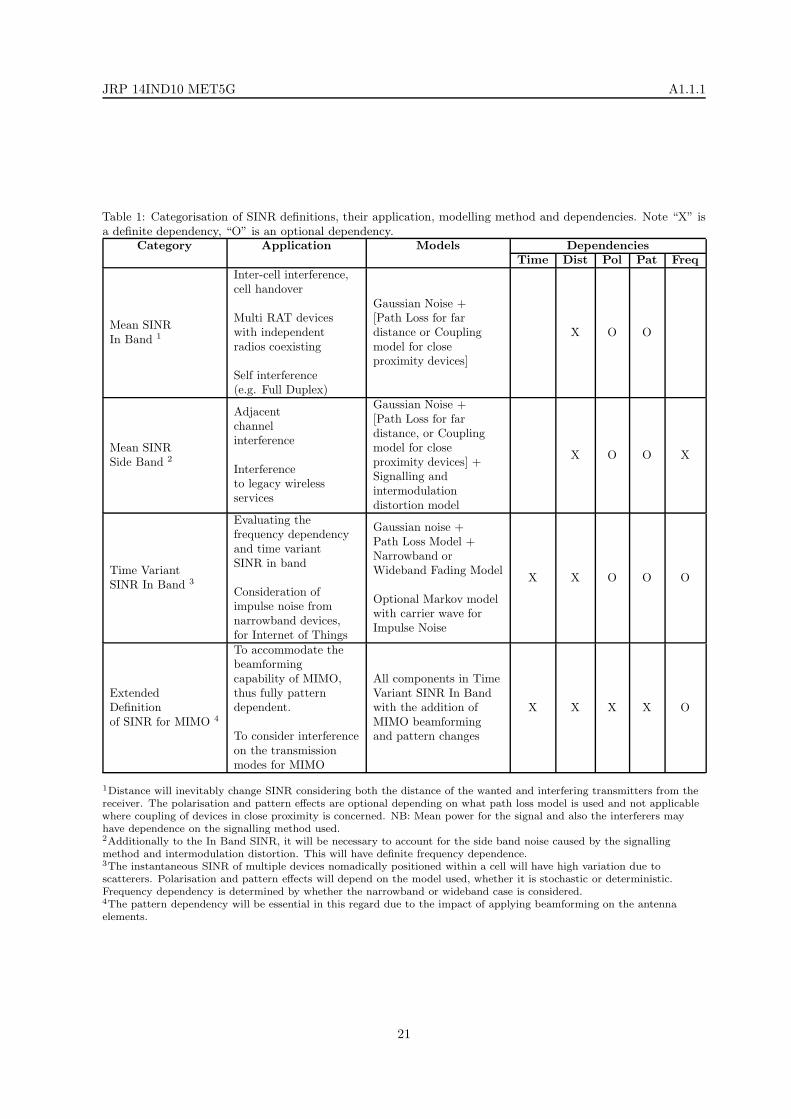
JRP 14IND10 MET5G A1.1.1
Table 1: Categorisation of SINR definitions, their application, modelling method and dependencies. Note “X” is
a definite dependency, “O” is an optional dependency.
Category Application Models DependenciesTime Dist Pol Pat Freq
Mean SINRIn Band 1
Inter-cell interference,cell handover
Multi RAT deviceswith independentradios coexisting
Self interference(e.g. Full Duplex)
Gaussian Noise +[Path Loss for fardistance or Couplingmodel for closeproximity devices]
X O O
Mean SINRSide Band 2
Adjacentchannelinterference
Interferenceto legacy wirelessservices
Gaussian Noise +[Path Loss for fardistance, or Couplingmodel for closeproximity devices] +Signalling andintermodulationdistortion model
X O O X
Time VariantSINR In Band 3
Evaluating thefrequency dependencyand time variantSINR in band
Consideration ofimpulse noise fromnarrowband devices,for Internet of Things
Gaussian noise +Path Loss Model +Narrowband orWideband Fading Model
Optional Markov modelwith carrier wave forImpulse Noise
X X O O O
ExtendedDefinitionof SINR for MIMO 4
To accommodate thebeamformingcapability of MIMO,thus fully patterndependent.
To consider interferenceon the transmissionmodes for MIMO
All components in TimeVariant SINR In Bandwith the addition ofMIMO beamformingand pattern changes
X X X X O
1Distance will inevitably change SINR considering both the distance of the wanted and interfering transmitters from the
receiver. The polarisation and pattern effects are optional depending on what path loss model is used and not applicable
where coupling of devices in close proximity is concerned. NB: Mean power for the signal and also the interferers may
have dependence on the signalling method used.2Additionally to the In Band SINR, it will be necessary to account for the side band noise caused by the signalling
method and intermodulation distortion. This will have definite frequency dependence.3The instantaneous SINR of multiple devices nomadically positioned within a cell will have high variation due to
scatterers. Polarisation and pattern effects will depend on the model used, whether it is stochastic or deterministic.
Frequency dependency is determined by whether the narrowband or wideband case is considered.4The pattern dependency will be essential in this regard due to the impact of applying beamforming on the antenna
elements.
21
JRP 14IND10 MET5G A1.1.1
References
[1] K. A. Hamdi, “On the statistics of signal-to-interference plus noise ratio in wireless communications,”IEEE Trans. Commun., vol. 57, no. 11, pp. 3199–3204, 2009.
[2] L. Zhao and A. M. Haimovich, “Performance of ultra-wideband communications in the presence ofinterference,” IEEE J. Select. Areas Commun., vol. 20, no. 9, pp. 1684–1691, 2002.
[3] T. Jia and D. I. Kim, “Analysis of average signal-to-interference-noise ratio for indoor UWB Rakereceiving system,” in IEEE Vehicular Technology Conference (VTC), Stockholm, Sweden, May 2005,pp. 1396–1400.
[4] M. Fernandez, I. Landa, A. Arrinda, R. Torre, and M. Velez, “Harmonization of Noise MeasurementMethods: Measurements of radio impulsive noise from a specific source,” IEEE Antennas Propagat.Mag., vol. 57, no. 5, pp. 64–72, 2015.
[5] “Methods for Measurements of Radio Noise,” ITU-R Recommendation Standard,” SM.1753-2, 2012.[Online]. Available: http://www.itu.int/rec/R-REC-SM.1753-2-201209-I/
[6] M. Cheffena, “Propagation Channel Characteristics of Industrial Wireless Sensor Networks,” IEEEAntennas Propagat. Mag., vol. 58, no. 1, pp. 66–73, 2016.
[7] M. Cheffena, “Industrial wireless sensor networks: Channel modeling and performance evaluation,”EURASIP J. Wireless Communications Networking, vol. 2012, no. 297, pp. 1–8, 2012.
[8] A. Iyer, C. Rosenberg, and A. Karnik, “What is the right model for wireless channel interference?”IEEE Trans. Wireless Commun., vol. 8, no. 5, pp. 2662–2671, 2009.
[9] “The ns2 network simulator,” http://www.isi.edu/nsnam/ns/, Accessed: 2015-11-30.
[10] S. Ariyavisitakul and L. F. Chang, “Signal and interference statistics of a CDMA system withfeedback power control,” IEEE Trans. Commun., vol. 41, no. 11, pp. 1626–1634, 1993.
[11] S. Ariyavisitakul, “Signal and interference statistics of a CDMA system with feedback power controlII,” IEEE Trans. Commun., vol. 42, no. 234, pp. 597–605, 1994.
[12] P. Stuedi and G. Alonso, “Log-normal shadowing meets SINR: A numerical study of Capacity inWireless Networks,” in 4thAnnual IEEE Communications Society Conference on Sensor, Mesh andAd Hoc Communications and Networks (SECON), San Diego, CA, June 2007, pp. 550–559.
[13] A. Amate, S. Sofianos, M. Milosavljevic, P. Kourtessis, and J. M. Senior, “An efficient inter-siteinterference model for 4G wireless networks,” in IEEE International Conference on Communications(ICC), Budapest, Hungary, June 2013, pp. 5355–5359.
[14] H. Kim, H. Wang, S. Lim, and D. Hong, “On the Impact of Outdated Channel Information on theCapacity of Secondary User in Spectrum Sharing Environments,” IEEE Trans. Wireless Commun.,vol. 11, no. 1, pp. 284–295, 2012.
[15] “Technical Specification Group Radio Access Network; Evolved Universal Terrestrial Radio Access(E-UTRA); Physical layer procedures,” 3GPP TS 36.213, version 12.3.0 Release 12, 2014-09.[Online]. Available: http://www.3gpp.org/dynareport/36213.htm/
[16] “LTE; Evolved Universal Terrestrial Radio Access (E-UTRA); Radio Frequency (RF) systemscenarios,” 3GPP TR 36.942, version 8.1.0 Release 8, 2009-01. [Online]. Available: http://www.3gpp.org/dynareport/36942.htm/
[17] “Technical Specification Group Radio Access Network; Evolved Universal Terrestrial Radio Access(E-UTRA); Physical layer; Measurements,” 3GPP TS 36.214, version 12.0.0 Release 12, 2014-09.[Online]. Available: http://www.3gpp.org/dynareport/36214.htm/
22
JRP 14IND10 MET5G A1.1.1
[18] D. R. Jeske and A. Sampath, “Signal-to-Interference-plus-Noise Ratio Estimation for Wireless Com-munication Systems: Methods and Analysis,” Naval Research Logistics, vol. 51, no. 5, pp. 720–740,2004.
[19] M. Turkboylari and G. Stuber, “An efficient algorithm for estimating the signal-to-interference ratioin TDMA cellular systems,” IEEE Trans. Commun., vol. 46, no. 6, pp. 728–731, 1998.
[20] D. Ramakrishna, N. B. Mardayam, and R. Yates, “Subspace based SIR estimation for CDMA cellularsystems,” IEEE Trans. Veh. Technol., vol. 49, no. 5, pp. 1732–1742, 2000.
[21] P. Li, D. Paul, R. Narasimhan, and J. Cioffi, “On the Distribution of SINR for the MMSE MIMOReceiver and Performance Analysis,” IEEE Trans. Inform. Theory, vol. 52, no. 1, pp. 271–286, 2006.
[22] W. L. Tan, P. Hu, and M. Portmann, “Experimental Evaluation of Measurement-based SINR Inter-ference Models,” in World of Wireless, IEEE International Symposium on Mobile and MultimediaNetworks (WoWMoM), San Francisco, CA, June 2012, pp. 1–9.
[23] M. Haenggi, J. G. Andrews, F. Baccelli, O. Dousse, and M. Franceschetti, “Stochastic Geometryand Random Graphs for the Analysis and Design of Wireless Networks,” IEEE J. Select. AreasCommun., vol. 27, no. 7, pp. 1029–1045, 2009.
[24] M. D. Renzo and P. Guan, “A Mathematical Framework to the Computation of the Error Probabilityof Downlink MIMO Cellular Networks by Using Stochastic Geometry,” IEEE Trans. Commun.,vol. 62, no. 8, pp. 2860–2879, 2014.
[25] M. Rumney, Ed., LTE and the Evolution to 4G Wireless: Design and Measurement Challenges,2nd ed. John Wiley & Sons, Inc, 2013.
[26] J. Padhye, S. Agarwal, V. N. Padmanabhan, L. Qiu, A. Rao, and B. Zill, “Estimation of linkinterference in static multihop wireless networks,” in Proc. ACM IMC, Berkeley, CA, June 2005, pp.28–28.
[27] A. Kashyap, S. Ganguly, and S. R. Das, “A measurement-based approach to modeling link capacityin 802.11-based wireless networks,” in Proc. ACM Mobicom, New York, NY, 2007, pp. 242–253.
[28] R. Maheshwari, S. Jain, and S. R. Das, “A measurement study of interference modeling and schedul-ing in low-power wireless networks,” in Proc. 6thACM conference on Embedded network sensorsystems (SenSys), New York, NY, 2008, pp. 141–154.
[29] “The ns3 network simulator,” https://www.nsnam.org/, Accessed: 2016-02-18.
[30] M. Mezzavilla, S. Dutta, M. Zhang, M. R. Akdeniz, and S. Rangan, “5G MmWave Module for theNs-3 Network Simulator,” in Proc. of the 18thACM International Conference on Modeling, Analysisand Simulation of Wireless and Mobile Systems, Cancun, Mexico, Mar. 2015, pp. 1–8.
[31] K. Venugopal, M. C. Valenti, and R. W. Heat, “Interference in finite-sized highly dense millimeterwave networks,” in Information Theory and Applications Workshop (ITA), San Diego, CA, Feb.2015, pp. 175–180.
[32] K. Venugopal, M. C. Valenti, and R. W. H. Jr., “Device-to-Device Millimeter Wave Communications:Interference, Coverage, Rate, and Finite Topologies,” arXiv, vol. abs/1506.07158, pp. 1–31, 2015.[Online]. Available: http://arxiv.org/abs/1506.07158
[33] X. Ge, K. Huang, C. X. Wang, X. Hong, and X. Yang, “Capacity Analysis of a Multi-Cell Multi-Antenna Cooperative Cellular Network with Co-Channel Interference,” IEEE Trans. Wireless Com-mun., vol. 10, no. 10, pp. 3298–3309, 2011.
[34] Y. Dong, Z. Chen, P. Fan, and K. Letaief, “Mobility-Aware Uplink Interference Model for 5GHeterogeneous Networks,” IEEE Trans. Wireless Commun., vol. PP, no. 99, pp. 1536–1276, 2015.
23

JRP 14IND10 MET5G A1.1.1
[35] M. Taranetz and M. Rupp, “A Circular Interference Model for Asymmetric Aggregate Interference,”arXiv, vol. abs/1505.05842, pp. 1–30, 2015. [Online]. Available: http://arxiv.org/abs/1505.05842
[36] C. Seol and K. Cheun, “A statistical inter-cell interference model for downlink cellular OFDMA net-works under log-normal shadowing and multipath Rayleigh fading,” IEEE Trans. Commun., vol. 57,no. 10, pp. 3069–3077, 2009.
[37] J. Luo, A. Iyer, and C. Rosenberg, “Throughput-Lifetime Trade-Offs in Multihop Wireless Networksunder an SINR-Based Interference Model,” vol. 10, no. 3, pp. 419–433, 2011.
[38] D. R. Jeske and A. Sampath, “Method of Estimating Signal-to-Interference + Noise Ratio (SINR),”Patent US20 030 016 740, Jan. 23, 2003.
[39] K. J. Olszewski, “SINR Measurement Method for OFDM Communications Systems,” PatentUS20 030 223 354, Dec. 4, 2004.
[40] M. D. Noes, D. Ktenas, L. Maret, and Y. Nasser, “Estimation of a Signal-to-Interference Plus NoiseRatio at the Output of an OFDM CDMA Receiver,” Patent US7 751 468, July 6, 2010.
[41] A. Kangas and M. Ringstrom, “Simplified Impairments Matrix Calculation for SINR Estimation,”Patent US7 986 919, June 26, 2011.
[42] S. Grant, “Pilot-Based SINR Estimator for MIMO Systems,” Patent US20 110 026 566, Feb. 3, 2011.
[43] S. Semenov, K. Ostman, A. Malkov, J. Vesma, and R. Paatelma, “Apparatus and Method for SINREstimation HSDPA MIMO Receiver,” Patent US20 120 201 285A1, Aug. 9, 2012.
[44] S. Sesia and A. Ancora, “Method to Estimate a Signal to Interference Plus Noise Ratio Based onSelection of the Samples and Corresponding Processing System,” Patent US20 120 310 573A1, Dec.6, 2012.
[45] Q. Zhang, Y. Li, and W. Liu, “Signal to Interference Plus Noise Ratio (SINR) Estimation Methodand Device,” Patent EP2 398269A1, Dec. 21, 2012.
[46] M. Jia, J. Ma, P. Zhu, and W. Tong, “Effective Signal Interference Plus Noise Ratio Estimation forMulti-Order Modulation,” Patent US8 416881, Apr. 9, 2013.
[47] S. Semenov and T. P. Tammilehto, “Estimation of the Signal to Interference and Noise Ratio (SINR)in Multiple Input Multiple Output (MIMO) Systems,” Patent US008 553 803B2, Oct. 8, 2013.
[48] C. S. Bontu, Z. Cai, Y. Yu, Y. Song, M. Fong, and R. Hu, “Procedure for Formulating a Signal toInterference Plus Noise Ratio,” Patent US20 140 233 408, Aug. 21, 2014.
[49] H. Mizrahi and I. Rosenhouse, “SNR Estimation,” Patent US008 630 335, Jan. 14, 2014.
[50] T. W. C. Brown, P. C. F. Eggers, and K. Olesen, “Simultaneous 5 GHz Co-channel MIMO Linksat Microcellular Boundaries: Interference or Cooperation?” IET Microw. Antennas Propag., vol. 1,no. 6, pp. 1152–1159, 2007.
[51] T. W. C. Brown, P. C. F. Eggers, and G. F. Pedersen, “Experimental interference assessment betweentwo independent and simultaneous 4x4 MIMO handset user links, operating at 5 GHz,” ElectronicsLett., vol. 46, no. 4, pp. 309–310, 2010.
[52] W. Zhang, Z. Zhang, and C. Tellambura, “Signal-to-Interference-Plus-Noise Ratio Analysis forMIMO-OFDM with Carrier Frequency Offset and Channel Estimation Errors,” in Wireless Commu-nications and Networking Conference (WCNC), Honolulu, HI, Mar. 2007, pp. 927–931.
[53] T. Abe and G. Bauch, “Effective SINR Computation for Maximum Likelihood Detector in MIMOSpatial Multiplexing Systems,” in Global Telecommunications Conference (GLOBECOM), Honolulu,HI, Nov. 2009, pp. 1–5.
24

JRP 14IND10 MET5G A1.1.1
[54] M. Arai, T. Seki, K. Hiraga, T. Nakagawa, and K. Uehara, “Study on short-range MIMO transmis-sion using interference cancellation by antenna directivities,” in Asia-Pacific Microwave ConferenceProceedings (APMC), Seoul, South Korea, Nov. 2013, pp. 395–397.
[55] M. I. Rahman, E. de Carvalho, and R. Prasad, “Impact of MIMO Co-Channel Interference,”in 18thInternational Symposium on Personal, Indoor and Mobile Radio Communications, Athens,Greece, Sept. 2007, pp. 1–5.
[56] J. Hoydis, S. ten Brink, and M. Debbah, “Massive MIMO in the UL/DL of cellular networks: Howmany antennas do we need?” IEEE J. Select. Areas Commun., vol. 31, no. 2, pp. 160–171, 2013.
[57] E. Bjornson, E. G. Larsson, and M. Debbah, “Massive MIMO for Maximal Spectral Efficiency: HowMany Users and Pilots Should Be Allocated?” IEEE Trans. Wireless Commun., vol. 15, no. 2, pp.1293–1308, 2016.
[58] H. Liu, H. Gao, A. Hu, and T. Lv, “Low-complexity transmission mode selection in MU-MIMOsystems,” in 21st Int. Conf. on Telecommunications (ICT), Lisbon, Portugal, May 2014, pp. 6–10.
[59] J. Jing and X. Zheng, “A Downlink Max-SINR Precoding for Massive MIMO System,” InternationalJournal of Future Generation Communication and Networking, vol. 7, no. 3, pp. 107–116, 2014.
[60] S. L. H. Nguyen and A. Ghrayeb, “Precoding for multicell massive MIMO systems with compressiverank-q channel approximation,” in 24thInternational Symposium on Personal, Indoor and MobileRadio Communications, London, UK, Sept. 2013, pp. 1227–1232.
[61] S. Feng, G. Chen, W. Mao, S. Berber, and Y. Xiaohu, “Probability density derivation and analysisof SINR in massive MIMO systems with MF beamformer,” arXiv, vol. abs/1411.0080, pp. 1–12,2014. [Online]. Available: http://arxiv.org/abs/1411.0080
[62] “Massive MIMO Info Point,” https://massivemimo.eu/research-library, Accessed: 2015-11-30.
[63] H. Q. Ngo, “Massive MIMO: Fundamentals and System Designs,” Ph.D. dissertation, LinkopingUniversity, Sweden, Department of Electrical Engineering, 2013.
[64] “IEEE 802.16 Published Standards and Drafts,” http://www.ieee802.org/16/published.html, Ac-cessed: 2016-01-12.
[65] “LTE; Evolved Universal Terrestrial Radio Access (E-UTRA); User Equipment (UE) radiotransmission and reception,” 3GPP TS 36.101, version 12.5.0 Release 12, 2014-11. [Online].Available: http://www.3gpp.org/dynareport/36101.htm
[66] “LTE; Evolved Universal Terrestrial Radio Access (E-UTRA); Physical channels and modulation,”3GPP TS 36.211, version 10.0.0 Release 13, 2016-01. [Online]. Available: http://www.3gpp.org/dynareport/36201.htm
[67] “LTE; Evolved Universal Terrestrial Radio Acces (E-UTRA); Physical channels and modulation,”3GPP TS 36.211, version 13.0.0 Release 13, 2016-01. [Online]. Available: http://www.3gpp.org/dynareport/36211.htm
[68] “NGMN 5G White paper,” https://www.ngmn.org/uploads/media/NGMN 5G White Paper V1 0.pdf, Accessed: 2015-11-30.
[69] “Looking ahead to 5G,” http://networks.nokia.com/file/28771/5g-white-paper, NOKIA, Accessed:2016-05-31.
[70] “5G Systems,” https://www.ericsson.com/res/docs/whitepapers/what-is-a-5g-system.pdf, Ericsson,Accessed: 2016-05-31.
[71] “5G: A Technology Vision,” http://www.huawei.com/5gwhitepaper/, Huawei, Accessed: 2016-05-31.
25
JRP 14IND10 MET5G A1.1.1
[72] “5G Vision,” http://www.samsung.com/global/business-images/insights/2015/Samsung-5G-Vision-0.pdf, Samsung, Accessed: 2016-05-31.
[73] “DOCOMO 5G White paper,” https://www.nttdocomo.co.jp/english/binary/pdf/corporate/technology/whitepaper 5g/DOCOMO 5G White Paper.pdf, DOCOMO, Accessed: 2016-05-31.
[74] “White Papers on key 5G technologies,” http://www.nec.com/en/press/201602/global 20160222 03.html, NEC, Accessed: 2016-05-31.
[75] J. G. Andrews, S. Buzzi, W. Choi, S. V. Hanly, A. Lozano, A. C. K. Soong, and J. C. Zhang, “WhatWill 5G Be?” IEEE J. Select. Areas Commun., vol. 32, no. 6, pp. 1065–1082, 2014.
[76] X. Ge, H. Cheng, M. Guizani, and T. Han, “5G wireless backhaul networks: challenges and researchadvances,” IEEE Network, vol. 28, no. 6, pp. 6–11, 2014.
[77] V. Jungnickel, K. Manolakis, W. Zirwas, B. Panzner, V. Braun, M. Lossow, M. Sternad, R. Apelfrojd,and T. Svensson, “The role of small cells, coordinated multipoint, and massive MIMO in 5G,” IEEECommun. Mag., vol. 528, no. 5, pp. 44–51, 2014.
[78] “UK Spectrum Policy Forum (UK SPF),” https://www.techuk.org/about/uk-spectrum-policy-forum, Accessed: 2015-11-30.
[79] “UK Spectrum Policy Forum, 5G working group vision,” https://www.techuk.org/events/meeting/item/1673-uk-5g-vision, Accessed: 2015-11-30.
[80] B. Narasimhan, D. Wang, S. Narayanan, H. Minn, , and N. Al-Dhahir, “Digital compensation offrequency-dependent joint Tx/Rx I/Q imbalance in OFDM systems under high mobility,” IEEE J.Select. Topics Sign. Proces., vol. 3, no. 3, pp. 405–417, 2009.
[81] Y. Zou, M. Valkama, and M. Renfors, “Analysis and compensation of transmitter and receiver I/Qimbalances in space-time coded multiantenna OFDM systems,” EURASIP J. Wirel. Comm. andNetworking, vol. 56, no. 391025, pp. 1–16, 2008.
[82] Y. Zou, M. Valkama, and M. Renfors, “Performance analysis of spatial multiplexing MIMO-OFDMsystems under frequency-selective I/Q imbalances,” in Int. Wireless Communications and MobileComputing Conf. (IWCMC09), Leipzig, Germany, June 2009, pp. 1381–1386.
[83] O. Ozdemir, R. Hamila, and N. Al-Dhahir, “I/Q imbalance in multiple beamforming OFDMtransceivers: SINR analysis and digital baseband compensation,” IEEE Trans. Commun., vol. 61,no. 5, pp. 1914–1925, 2013.
[84] N. Bhushan, J. Li, D. Malladi, R. Gilmore, D. Brenner, A. Damnjanovic, R. T. Sukhavasi, C. Patel,and S. Geirhofer, “Network Densification: The Dominant Theme for Wireless Evolution into 5G,”IEEE Commun. Mag., vol. 52, no. 2, pp. 82–89, 2014.
[85] C. Wang, F. Haider, X. Gao, X.-H. You, Y. Yang, D. Yuan, H. M. Aggoune, H. Haas, S. Fletcher,and E. Hepsaydir, “Cellular Architecture and Key Technologies for 5G Wireless CommunicationNetworks,” IEEE Commun. Mag., vol. 52, no. 2, pp. 122–130, 2014.
[86] W. Nam, D. Bai, J. Lee, and I. Kang, “Advanced Interference Management for 5G Cellular Networks,”IEEE Commun. Mag., vol. 52, no. 2, pp. 52–60, 2014.
[87] M. N. Tehrani, M. Uysal, and H. Yanikomeroglu, “Device-to-Device Communication in 5G CellularNetworks: Challenges, Solutions, and Future Directions,” IEEE Commun. Mag., vol. 52, no. 5, pp.86–92, 2014.
[88] T. S. Rappaport, S. Sun, R. Mayzus, H. Zhao, Y. Azar, K. Wang, G. N. Wong, J. K. Schulz,M. Samimi, and F. Gutierrez, “Millimeter Wave Mobile Communications for 5G Cellular: It WillWork!” IEEE Access, vol. 1, pp. 335–349, 2013.
26
JRP 14IND10 MET5G A1.1.1
[89] “EMPIR 14IND10 ’MET5G’ Metrology for 5G Communications,” http://empir.npl.co.uk/met5g/,Accessed: 2016-02-18.
[90] D. A. Humphreys, T. Brown, and J. R. Kelly, “Notes from the SINR workshop 9th October 2015 ,”Institute for Communication Systems, Univ. of Surrey, UK,” MET5G project Activity report, 2015.
[91] S. Dash, F. Pythoud, P. Leuchtmann, and J. Leuthold, “Traceable Power Measurement of LTESignals,” in 17thInternational Congress of Metrology, Paris, France, Sept. 2015, p. 12005.
[92] “EMRP IND51 ’MORSE’ Metrology for optical and RF communication systems,” http://projects.npl.co.uk/emrp-ind51-morse/, Accessed: 2016-02-18.
27