Embed Size (px)
Citation preview

EnglishPrinted in the U. S. A.
™™
MODELS 1420, 1620, 1720, 1920, AND 2120HIGH PERFORMANCE AIRLESS SPRAYER
TABLE OF CONTENTS:SAFETY . . . . . . . . . . . . . . . . . . . . . . . . . . . . . . . . . . . . . . 2-3COMPONENTS AND DESCRIPTION . . . . . . . . . . . . . . . . . . 4SETUP . . . . . . . . . . . . . . . . . . . . . . . . . . . . . . . . . . . . . . . . . 5PLUGGING IN THE SPRAYER . . . . . . . . . . . . . . . . . . . . . . . 6PRESSURE RELIEF PROCEDURE . . . . . . . . . . . . . . . . . . . 6PURGING AND PRIMING. . . . . . . . . . . . . . . . . . . . . . . . . . . 7SPRAYING . . . . . . . . . . . . . . . . . . . . . . . . . . . . . . . . . . . . . . 8SPRAYING TROUBLESHOOTING . . . . . . . . . . . . . . . . . . . . 9CLEANUP . . . . . . . . . . . . . . . . . . . . . . . . . . . . . . . . . . . 10-11STORAGE . . . . . . . . . . . . . . . . . . . . . . . . . . . . . . . . . . . . . 12MAINTENANCE . . . . . . . . . . . . . . . . . . . . . . . . . . . . . . . . . 13ACCESSORIES . . . . . . . . . . . . . . . . . . . . . . . . . . . . . . . . . 13FLUID SECTION . . . . . . . . . . . . . . . . . . . . . . . . . . . . . . . . 14TROUBLESHOOTING . . . . . . . . . . . . . . . . . . . . . . . . . . . . 15PARTS LIST . . . . . . . . . . . . . . . . . . . . . . . . . . . . . . . . . 48-51WARRANTY . . . . . . . . . . . . . . . . . . . . . . . . . . . . . . . . . . . . 52
OWNER’S MANUAL • READ THIS MANUAL FOR COMPLETE INSTRUCTIONS
0803 • Form No. 0512770H
SPECIFICATIONS:Weight ..............................25 lbs (1420)
31 lbs. (1620, 1720 and 1920)40 lbs. (2120)
Capacity ...........................Up to .25 gallon (1 liter) per minute(1420 and 1620 Series)Up to .33 gallon (1.25 liters) per minute(1720 Series) Up to .42 gallon (1.6 liters) per minute(1920 Series)
Up to .45 gallon (1.71 liters) per minute(2120 Series)
Power source ...................1/2 Hp universal motor (1420 and1620 Series)5/8 Hp permanent magnet DC motor(1720 Series)3/4 Hp permanent magnet DC motor(1920 Series)7/8 Hp permanent magnet DC motor(2120 series)
Power requirement ...........15 amp minimum circuit on 115VAC, 60 Hz current.
Generator .........................8000 Watt.
Spraying pressure ............Up to 2800 psi.
Safety features .................Spray gun trigger lock andpressure diffuser; built-in tipsafety guard; priming knob forsafe pressure release.
Capability..........................Sprays a variety of paints, oilbase latex, primers, stains,preservatives and othernonabrasive materials, includingpesticides and liquid fertilizers.
1-800-686-8525Wagner Technical Service
Need help? Call us first for answers fast.Call Wagner Spray Tech toll-free if you have any comments or problems with this product.
1770 Fernbrook Lane, Minneapolis, MN 55447
http://www.wagnerspraytech.comVisit us on the world wide web!
This pump should not be used with textured materials,block filler, or asphalt sealer.
U.S. Patent No. 6,435,846
This pump is available in two models: astand model and a cart model. The cart
model is shown in this manual. Allinformation given for the cart model
applies to the stand model except whereindicated.

HAZARD: INJECTION INJURYA high pressure paint stream produced bythis equipment can pierce the skin andunderlying tissues, leading to serious injuryand possible amputation. SEE A PHYSICIANIMMEDIATELY.DO NOT TREAT AN INJECTION INJURY AS A SIMPLE CUT!Injection can lead to amputation. See a physician immediately.The maximum operating range of the gun is 2800PSI/193BAR fluid pressure.PREVENTION:
• NEVER aim the gun at any part of the body. • NEVER allow any part of the body to touch the fluid stream.
DO NOT allow body to touch a leak in the fluid hose.• NEVER put your hand in front of the gun. Gloves will not
provide protection against an injection injury.• ALWAYS lock the gun trigger, shut the pump off, and
release all pressure before servicing, cleaning the tip orguard, changing tip, or leaving unattended. Pressure willnot be released by turning off the motor. ThePRIME/SPRAY knob must be turned to PRIME to relievethe pressure. Refer to the PRESSURE RELIEFPROCEDURE (page 6) described in the pump manual.
• ALWAYS keep the tip guard in place while spraying. Thetip guard provides some protection but is mainly a warningdevice.
• ALWAYS remove the spray tip before flushing or cleaningthe system.
• Paint hose can develop leaks from wear, kinking andabuse. A leak can inject material into the skin. Inspectthe hose before each use.
• NEVER use a spray gun without a working trigger lockand trigger guard in place.
• All accessories must be rated at or above 2800 PSI/193BAR. This includes spray tips, guns, extensions, and hose.
HAZARD: HAZARDOUS VAPORSPaints, solvents, insecticides, and othermaterials can be harmful if inhaled or come incontact with the body. Vapors can causesevere nausea, fainting, or poisoning.
PREVENTION:
• Use a respirator or mask if vapors can beinhaled. Read all instructions suppliedwith the mask to be sure it will provide thenecessary protection.
• Wear protective eyewear.
• Wear protective clothing as required bycoating manufacturer.
NOTE TO PHYSICIAN:Injection into the skin is a traumatic injury. It is importantto treat the injury as soon as possible. DO NOT delaytreatment to research toxicity. Toxicity is a concern withsome coatings injected directly into the blood stream.Consultation with a plastic surgeon or reconstructivehand surgeon may be advisable.
2 1-800-686-8525 © 2002 Wagner Spray Tech - All rights reserved.
HAZARD: EXPLOSION OR FIRE Solvent and paint fumes can explode or ignite.Property damage and/or severe injury can occur.
PREVENTION:
• Provide extensive exhaust and fresh airintroduction to keep the air within the spray area free fromaccumulation of flammable vapors.
• Avoid all ignition sources such as staticelectric sparks, open flames, pilot lights,electrical appliances, and hot objects.Connecting or disconnecting power cordsor working light switches can make sparks.
• Do not smoke in spray area.• Fire extinguisher must be present and in good working
order.• Place paint pump at least 20 feet from the spray object in a
well ventilated area (add more hose if necessary).Flammable vapors are often heavier than air. Floor areamust be extremely well ventilated. The paint pump containsarcing parts that emit sparks and can ignite vapors.
• The equipment and objects in and around the spray areamust be properly grounded to prevent static sparks.
• Use only conductive or grounded high pressure fluid hose.Gun must be grounded through hose connections.
• Power cord must be connected to a grounded circuit.• Always flush unit into a separate metal container, at low
pump pressure, with spray tip removed. Hold gun firmlyagainst side of container to ground container and preventstatic sparks.
• Follow the material and solvent manufacturer's warningsand instructions.
• Use extreme caution when using materials with aflashpoint below 70° F (21° C). Flashpoint is thetemperature that a fluid can produce enough vapors toignite.
• Plastic can cause static sparks. Never hang plastic toenclose a spray area. Do not use plastic drop clothswhen spraying flammable materials.
• Use lowest possible pressure to flush equipment.GAS ENGINE (WHERE APPLICABLE)Always place pump outside of structure in fresh air. Keep allsolvents away from the engine exhaust. Never fill fuel tank witha running or hot engine. Hot surface can ignite spilled fuel.Always attach ground wire from pump unit to a grounded object,such as a metal water pipe. Refer to enigine owner’s manualfor complete safety information.
HAZARD: EXPLOSION HAZARD DUE TOINCOMPATIBLE MATERIALS
Will cause property damage or severe injury.PREVENTION:
• Do not use materials containing bleach orchlorine.
• Do not use halogenated hydrocarbon solvents such asbleach, mildewcide, methylene chloride and 1,1,1 -trichloroethane. They are not compatible with aluminum.
• Contact your coating supplier about the compatibility ofmaterial with aluminum.
English
SAFETY INFORMATION • READ ALL SAFETY
INFORMATION BEFORE OPERATING THE EQUIPMENT
HAZARD: GENERALCan cause severe injury or property damage.
PREVENTION:• Read all instructions and safety precautions before
operating equipment.• Follow all appropriate local, state, and national codes
governing ventilation, fire prevention, and operation. • The United States Government Safety Standards have
been adopted under the Occupational Safety and HealthAct (OSHA). These standards, particularly part 1910 ofthe General Standards and part 1926 of the ConstructionStandards should be consulted.
• Use only manufacturer authorized parts. User assumesall risks and liabilities when using parts that do not meetthe minimum specifications and safety requirements of thepump manufacturer.
• Before each use, check all hoses for cuts, leaks, abrasionor bulging of cover. Check for damage or movement ofcouplings. Immediately replace the hose if any of theseconditions exist. Never repair a paint hose. Replace itwith another grounded high-pressure hose.
• All hoses, swivels, guns, and accessories must bepressure rated at or above 2800PSI/193 BAR.
• Do not spray outdoors on windy days.• Wear clothing to keep paint off skin and hair.
IMPORTANT ELECTRICAL INFORMATION
Use only a 3-wire extension cord that has a 3-blade groundingplug and a 3-slot receptacle that will accept the plug on theproduct. Make sure your extension cord is in good condition.When using an extension cord, be sure to use one heavyenough to carry the current your product will draw. Anundersized cord will cause a drop in line voltage resulting in lossof power and overheating. A 14 or 12 gauge cord isrecommended. If an extension cord is to be used outdoors, itmust be marked with the suffix W-A after the cord typedesignation. For example, a designation of SJTW-A wouldindicate that the cord would be appropriate for outdoor use.
THE 1420 AND 1620 SERIES UNITS ARE PROVIDED WITHA NON-RESETABLE THERMAL OVERLOAD. THE 1720,1920 AND 2120 SERIES UNITS ARE PROVIDED WITH AREPLACEABLE FUSE.
• Always disconnect the motor from the power supplybefore working on the equipment.
The cause of the overload should be corrected beforerestarting. Take to Service Center.
CAUTION
Do not use more than 100 feet of hose. If you need topaint further than 100 feet from your power source,use more extension cord, not more paint hose.
CAUTION
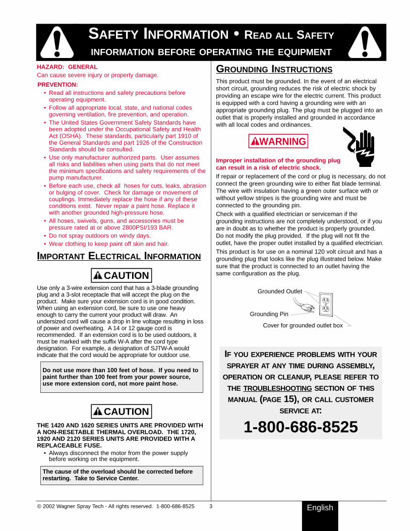
GROUNDING INSTRUCTIONSThis product must be grounded. In the event of an electricalshort circuit, grounding reduces the risk of electric shock byproviding an escape wire for the electric current. This productis equipped with a cord having a grounding wire with anappropriate grounding plug. The plug must be plugged into anoutlet that is properly installed and grounded in accordancewith all local codes and ordinances.
Improper installation of the grounding plugcan result in a risk of electric shock.If repair or replacement of the cord or plug is necessary, do notconnect the green grounding wire to either flat blade terminal.The wire with insulation having a green outer surface with orwithout yellow stripes is the grounding wire and must beconnected to the grounding pin.Check with a qualified electrician or serviceman if thegrounding instructions are not completely understood, or if youare in doubt as to whether the product is properly grounded.Do not modify the plug provided. If the plug will not fit theoutlet, have the proper outlet installed by a qualified electrician.This product is for use on a nominal 120 volt circuit and has agrounding plug that looks like the plug illustrated below. Makesure that the product is connected to an outlet having thesame configuration as the plug.
IF YOU EXPERIENCE PROBLEMS WITH YOUR
SPRAYER AT ANY TIME DURING ASSEMBLY,OPERATION OR CLEANUP, PLEASE REFER TO
THE TROUBLESHOOTING SECTION OF THIS
MANUAL (PAGE 15), OR CALL CUSTOMER
SERVICE AT:
1-800-686-8525
Grounded Outlet
Grounding Pin
Cover for grounded outlet box
WARNING
© 2002 Wagner Spray Tech - All rights reserved. 1-800-686-8525 3 English
SAFETY INFORMATION • READ ALL SAFETY
INFORMATION BEFORE OPERATING THE EQUIPMENT

O
l
SP
RAY
PR
IME
SPRAY
PRIME
PRIME/SPRAY knob
PRIME position SPRAY position
ON/OFFswitch
O = OFFl = ON
PRIME/SPRAY
knobSpray
gun
Spraytip
Hosebracket
Handle
Motorhousing
Lubricating area (on front
of face plate
Pail bracket
Spray hose
Returntube
Fluidsection
Suctiontube
Suction set screen
Customer Service: 800-686-8525 4 © 2002 Wagner Spray Tech - All rights reserved.English
COMPONENTS AND DESCRIPTIONCOMPONENTSThe shipping carton for your painting system contains the following:• Suction set and return tube• Spray gun with filter • Spray tip assembly (see chart below)• 50 foot long, 1/4 inch diameter pressure hose• Separating Oil
CONTROLS AND FUNCTIONSON/OFF Switch ................The ON/OFF switch turns the unit on
and off (O=OFF, l=ON).
Suction Set .......................Fluid is drawn through the suctionset into the pump.
Fluid Section ....................A piston in the fluid section moves upand down to create the suction thatdraws fluid through the suction set.
Spray Gun ........................The spray gun controls the deliveryof the fluid being pumped. The gunmodel you have depends on your
sprayer model (refer to SprayGun/Tip Chart, below).
Spray Hose ......................The spray hose connects the gun tothe pump.
Return Tube......................Fluid is sent back out through thereturn tube to the original container.
PRIME/SPRAY Knob........The PRIME/SPRAY knob directs fluidto the spray hose when set to SPRAYor the return tube when set to PRIME.The arrows on the PRIME/SPRAYknob shows the rotation directions forPRIME and SPRAY.
The PRIME/SPRAY knob is also usedto relieve pressure built up in thespray hose (Pressure ReliefProcedure, page 6)
Pressure Control Dial .......The pressure control dial controlsthe amount of force the pump usesto push the fluid (see graphic belowfor locations).
Pressure Control Dial
Rear of motor shroud,1420, 1620, 1720,and 1920 models.
Front face plate,2120 model
Spray hoseport
Pressure Control DialSprayerModel
GunModel
TipSize
Max.Size
RecommendedFilter
162017201920
GX-07GX-07GX-08
.013
.015
.017
.015
.017
.019
Yellow (fine)1420 GX-06 .013 .015 Yellow (fine)
Yellow (fine)White (medium)
2120 GX-10 .017 .021 White (medium)
Spray Gun/Tip Chart

© 2002 Wagner Spray Tech - All rights reserved. 5 Customer Service: 800-686-8525 English
TOOLS NEEDED FOR SETUP• Two adjustable wrenches• 3/16” allen wrench• Extension cord (refer to Important Electrical Information
(page 3).
Do not plug in the unit until setup is complete.
ATTACHING THE HANDLE (CART MODEL)1. Position the handle
against the cart so thatthe holes in the handleline up with the holes inthe cart.
2. Insert the bolts throughthe holes in the handleand cart and lockingwashers.
3. Tighten the wing nutsonto the bolts by hand.
ATTACHING THE HOSE BRACKET (CART MODEL)1. Insert the ends of the
hose bracket into theholes of the handle asshown.
ATTACHING THE PAIL BRACKET (CART MODEL)1. Position the pail bracket
against the unit so thatthe holes in the unit lineup with the holes in thebracket.
2. Insert the bolts through theholes in the bracket andthe unit.
3. Tighten the bolts with a3/16” allen wrench.
ATTACHING THE PAINT HOSE
1. Thread the high pressurehose to the paint hoseport.
2. Tighten with an adjustablewrench.
3. Remove pusher stemfrom inlet valve.
WARNING
ATTACHING THE SPRAY GUN
1. Thread spray gunonto the other endof the hose.
ATTACHING THE SUCTION SET & RETURN TUBE1. Attach the suction tube to the inlet valve and tighten firmly
by hand. Be sure that the threads are straight so that thefitting turns freely.
2. Press the return tube onto the return tube fitting.3. Squeeze clip over the return tube fitting to secure return
tube.
LOCKING AND UNLOCKING THE SPRAY GUN
Always lock the trigger off when attaching the spray tip orwhen the spray gun is not in use. Refer to Spray Gun/TipChart on page 4 to determine the gun model you have.
The spray tip SHOULD NOT be attached until after thesprayer and paint hose have been purged and primed.
GUN MODELS GX-08 AND
GX-10To lock the gun, turn the triggerlock forward and slightly downuntil it stops.
Gun locked(gun will not spray)
GX-08/10
GUN MODELS GX-06 AND
GX-07The gun is secured when thetrigger lock is at a 90° angle(perpendicular) to the trigger ineither direction.
Gun locked (gun will not spray)
GX-06/07
WARNING
Return tubefitting
Return tube
Inlet valve
Suction set
Clip
Hold the gun withone adjustablewrench, and tightenwith the other.
SETUP--ASSEMBLING THE SPRAYER

PLUGGING IN THE SPRAYER
1. Check that the ON/OFFswitch is in the OFFposition.
2. Plug the sprayer into aheavy duty groundedextension cord. Refer toImportant ElectricalInformation, page 3).
PRESSURE RELIEF PROCEDURE
Be sure to follow the pressure relief procedure (page 6)when shutting the unit off FOR ANY PURPOSE. Thisprocedure is used to relieve pressure from the spray hose.
1. Lock the spray gun off.
2. Flip the ON/OFF switch tothe OFF (O) position.
3. Unlock the spray gun,turn the PRIME/SPRAYknob to PRIME, andtrigger spray gun intopaint bucket.
4. Lock the spray gun.
PAINT STRAININGIt is recommended that in order to avoid premature tip and gunplugging you should strain your paint before spraying. Followmanufacturer’s recommendations.
SP
RAY
PR
IME
o
GX-08/10
GX-06/07
WARNING
o
This column contains instructions that will be repeatedthroughout this manual.
Customer Service: 800-686-8525 6 © 2002 Wagner Spray Tech - All rights reserved.
CHOOSING THE CORRECT SPRAY GUN FILTERUse the proper gun filter based on the tip size being used.
BEFORE YOU PRIME THE SPRAYERBefore priming, squirt a teaspoon of separating oil (P/N 0279920included with unit) into the indicated area. Light household oilcan be substituted if necessary. Do not put more than ateaspoon into the lubricating area. Too much oil will leak downinto your paint.
All units are performance-tested at the factory and are shippedwith test fluid in the fluid section to prevent corrosion duringshipment and storage.
• Whether you are going to spray latex or oil-basedpaints, this fluid must be purged and thoroughly cleanedout of the system (follow Purging and Priming the Pumpsteps, page 7).
If the pump has already been used you will need to purge thewater or solvent used in cleanup and storage.
IF YOUR UNIT HAS ALREADY BEEN USED. . .
IF YOUR UNIT IS NEW. . .
Part No. Tip Size FilterType
MeshNumber
Qty.Color ofFilter Body
0154918 .011 Extrafine 180 mesh0.084 mm
red 2 pack
2 pack
2 pack
0154675 .013 - .015 Fine 100 mesh0.140 mm
yellow
0154842 .017 - .023 Medium 50 mesh0.315 mm
white
English
BEFORE YOU BEGIN

© 2002 Wagner Spray Tech - All rights reserved. 7 Customer Service: 800-686-8525 English
PURGING & PRIMINGPURGING AND PRIMING THE PUMP
1. Place a full container ofpaint underneath thesuction tube.
2. Secure the return tubeinto a waste container.
3. Turn the pressure controldial to maximum pressure(+).
4. Turn the PRIME/SPRAYknob to PRIME.
5. Plug in the sprayer, andmove the ON/OFF switchto the ON position.
6. Switch the pump to OFF (O).7. Remove the return tube from the waste container and
place it in its operating position above the container ofpaint. Use the metal clip to bind the two hoses together.
Your sprayer is now purged. Move to Purging andPriming the Spray Hose.
The unit will begin to draw paint up the suction tube,into the pump, and out the return tube. Let the unitcycle long enough to remove test fluid from the pump,or until paint is coming from the return tube.
l
SP
RAY
PR
IME
Returntube
Suctiontube
PURGING AND PRIMING THE SPRAY HOSE
1. Unlock the spray gun andturn PRIME/SPRAY knobto PRIME.
2. Trigger and HOLD thespray gun into a wastecontainer.
3. While holding the trigger,switch the pump ON (l).
4. While holding the trigger,turn the PRIME/SPRAYknob to SPRAY. Hold thetrigger until all air, water, orsolvent is purged from thespray hose and paint isflowing freely (readwarnings below).
Keep hands clear from fluid stream.
Using a metal container, groundthe gun by holding it against theedge of the container whileflushing. Failure to do so maylead to a static electric dischargewhich may cause a fire.If the PRIME/SPRAY knob is stillon SPRAY, there will be high pressure in the hose andspray gun until the PRIME/SPRAY knob is turned to PRIME.
5. Release trigger, turn thePRIME/SPRAY knob toPRIME and turn pumpOFF (O).
6. Trigger the gun into thewaste container once moreto be sure that no pressureis left in the hose.
7. Lock the spray gun off. 8. Thread the spray tip guard assembly onto the gun.
Tighten by hand.
Your hose is now purged and primed. You are ready topaint.
Begintighteningthe tip at
this angle
to achievethe desiredspray anglewhen tight.
o
SP
RAY
PR
IME
WARNING
WARNING
SPRAY
PRIME
Your spray tip SHOULDNOT be attached to yourspray gun when purgingyour spray hose.
SP
RAY
PR
IME

PRACTICE
Be sure that the paint hose is free of kinks and clear ofobjects with sharp cutting edges.
1. Switch the pump ON (l)and turn thePRIME/SPRAY knob toSPRAY.
2. Turn the pressure contoldial to its highest setting(+). The spray hoseshould stiffen as paintbegins to flow through it.
3. When the motor shuts off, unlock the spray gun and spraya test area to check the spray pattern.
SPRAYING TECHNIQUEThe key to a good paint job is an even coating over the entiresurface. This is done by using even strokes. Follow the TIPS,below.
Keep stroke smooth and at an even speed.
Even coat throughout
Approximately10 to 12 inches
TIP: Keep your arm moving at a constant speed andkeep the spray gun at a constant distance fromthe surface. The best spraying distance is 10 to12 inches between the spray tip and the surface.
The pressure controldial can be adjusted upor down to achieve thedesired spray pattern.
Good spray pattern
Paint tailing pattern
When enough pressure has built up in the hose, themotor will shut off automatically. The motor will cycleon and off automatically as it needs pressure.
SPRAY
PRIME
CAUTION
Customer Service: 800-686-8525 8 © 2002 Wagner Spray Tech - All rights reserved.
ADDITIONAL TIPSOverlap each stroke by about 30%. This will ensure aneven coating.When you stop painting, follow PRESSURE RELIEFPROCEDURE.IF YOU EXPECT TO BE AWAY FROM YOUR SPRAYERFOR MORE THAN ONE HOUR, FOLLOW THE SHORT-TERM CLEANUP PROCEDURE DESCRIBED IN THESTORAGE SECTION OF THIS MANUAL (page 12).
Proper way to trigger the spray gun
Approximately10 to 12 inches
Keep strokeeven
Start stroke End strokePull trigger Release triggerKeep steady
TIP: The spray gun should be triggered by turning iton and off with each stroke. Do not trigger thegun during the middle of a stroke. This will resultin an uneven spray and splotchy coverage.
Heavy Coat
Do not flex wrist while spraying.
Light Coat Light Coat
TIP: Keep the spray gun at right angles to thesurface. This means moving your entire armback and forth rather than just flexing your wrist.
Approximately10 to 12 inches
Wrong way
Right way
TIP: Keep the spray gun perpendicular to thesurface, otherwise one end of the pattern willbe thicker than the other.
English
SPRAYING

© 2002 Wagner Spray Tech - All rights reserved. 9 Customer Service: 800-686-8525 English
UNCLOGGING THE SPRAY TIP
Do not attempt to unclog or clean the tip with your finger.
Do not use a needle or other sharp pointed instrument toclean the tip. The hard tungsten carbide can chip. If the spray pattern becomes distorted or stops completelywhile the gun is triggered, follow these steps:
1. Release the trigger and lock the gun off.
2. Rotate the reversible tip arrow 180° so that the point ofthe arrow is toward the rear of the gun (CLEAN position).
3. Turn the PRIME/SPRAYknob to SPRAY.
4. Unlock the gun and squeezethe trigger, pointing the gunat a scrap piece of wood orcardboard. This allowspressure in the spray hose toblow out the obstruction.When the nozzle is clean,paint will come out in a straight, high pressure stream.
5. Release the trigger and lock the gun off.
6. Reverse the tip so thearrow points forwardagain (SPRAY position).
7. Unlock the gun andresume spraying.
If paint still will not spray from the spray tip, follow theother steps on the next column.
Under pressure, the spray tipmay be very difficult to turn.Turn the PRIME/SPRAY knobto PRIME and trigger the gun.This will relieve pressure andthe tip will turn more easily.
GX-08/10
GX-06/07
CAUTION
WARNING
The following is a short list of minor difficulties you mightencounter while spraying. If any of these occur, it willreduce the flow of paint, making your spray pattern poor, orpaint will fail to spray from the gun.
• Clogged spray tip• Clogged gun filter• Clogged suction set screen
Follow the guidelines on this page to correct any one ofthese problems.
CLEANING THE SPRAY GUN FILTER
This filter must be cleaned every timeyou use your sprayer. When using thicker paints, the filtermight need to be cleaned more often.
1. Perform Pressure ReliefProcedure (page 6).
2a. If you have a model GX-06/07spray gun, unscrew the fitting fromthe bottom of the spray gun usingan adjustable wrench, making surenot to lose the spring.
2b. If you have a model GX-08/10 spray gun, unclip thetrigger guard from the filter housing by pulling outwardfrom the filter housing. Unscrew the housing.
3. Remove the filter from the spray gun housing and cleanwith the appropriate cleaning solution (warm, soapy waterfor latex paints, mineral spirits for oil-based materials).
4. Inspect the filter for holes (see Hole picture, above).Replace if holes are found.
NEVER POKE THE FILTER WITH A SHARP INSTRUMENT!5. Replace the cleaned filter, tapered end first, into the gun
housing.
6a. For the GX-06/07, replace the spring and the fitting.Tighten with an adjustable wrench.
6b. For the GX-08/10, replace the housing and snap thetrigger guard back into the housing.
CLEANING THE SUCTION SET SCREENThe screen at the bottom of the suction set may also needcleaning. Check it every time you change paint buckets.
1. Remove the screen by pulling itout of the retainer with a plier.
2. Clean the screen with theappropriate cleaning solution(warm, soapy water for latexpaints, mineral spirits for oil-based paints).
If after having completed all of the steps on this pageyou are still experiencing problems spraying, refer to theTROUBLESHOOTING guide (page 15).
The tapered end of the filter must be loaded properlyinto the gun. Improper assembly will result in aplugged tip or no flow from the gun.
CAUTION
Housing
Filter
Triggerguard
GX-08/10
Filter
Spring
Fitting
Housing
GX-06/07
Pin hole
Filter top
SPRAYING TROUBLESHOOTING

IMPORTANT CLEANING
NOTES!
READ THESE NOTES AND
WARNINGS BEFORE YOU
START TO CLEAN YOUR
SPRAYER!
• When using latex paints, cleanyour sprayer and componentsusing warm, soapy water.When using oil-based paints,use mineral spirits.
• Do not use mineral spirits onlatex paint, or the mixture willturn into a jelly-like substancewhich is difficult to remove.
• No matter which cleaningsolution you use, make sure todispose of it properly whenfinished cleaning your sprayer.
• Thorough cleaning andlubrication of the sprayer isthe most important step youcan take to ensure properoperation after storage.
CALL 1-800-686-8525IF YOU HAVE ANY QUESTIONSREGARDING THE CLEANUP OF
YOUR SPRAYER
Customer Service: 800-686-8525 10 © 2002 Wagner Spray Tech - All rights reserved.English
CLEANUPPURGING THE PAINT HOSE
1. Lock the gun and remove spray tipassembly.
2. Submerge suction set into a bucketwith appropriate cleaning solution.
3. Hold the spray gun against the side ofthe paint can and hold the trigger.
4. While holding the trigger, turn thepump ON (l), and turn thePRIME/SPRAY knob to SPRAY.
5. Release the trigger.6. Hold the spray gun against the side of
a separate container and hold thetrigger.
7. Trigger the gun until the fluid comingout of the gun is clear.
8. Turn the PRIME/SPRAY knob toPRIME and trigger gun once more torelieve pressure.
9. Move on to Cleaning the SuctionSet.
Let the pump run until all paint ispurged from the hose and cleaningsolution is coming out of the gun.
SPRAY
PRIME
l
These steps will allow you torecover excess paint left over in thepaint hose.
CLEANING THE SUCTION SET
1. Lock the gun and turnthe pump OFF (O).
2. Remove the suctionhose and return tubeand clean it using theappropriate cleaningsolution.
3. When suction set is clean, thread thesuction tube back onto the inletvalve, and replace the return tubeonto the return tube fitting. Replaceclip.
4. Submerge the suction set into abucket of NEW cleaning solution.
5. Turn the PRIME/SPRAY knob toPRIME, turn the pump to ON (l), andtrigger the gun into a waste containerto relieve the pressure.
6. Let the pump circulate the cleaningsolution through the suction set for 2-3 minutes.
7. Turn the pump OFF (O).8. Move on to Cleaning the Spray
Gun, next page.
SP
RAY
PR
IME
l
Return tubefitting
Return tube
Inlet valve
Suction set
Clip
You should also wipe the threads ofthe inlet valve, and remove andclean the suction set screen.
o
Special cleanup instructions for use withflammable solvents:
• ALWAYS FLUSH SPRAY GUN ATLEAST ONE HOSE LENGTHAWAY FROM SPRAY PUMP.
• If collecting flushed solvents inone gallon metal container, placeit into an empty five galloncontainer, then flush.
• Area must be free from vapors.• Follow all cleanup instructions.
WARNING

© 2002 Wagner Spray Tech - All rights reserved. 11 Customer Service: 800-686-8525 English
CLEANUP (CONTINUED)
1. Make sure the pump is switched OFF (O), thePRIME/SPRAY knob is turned to PRIME, and unplug thesprayer.
2. Remove spray gun from the paint hose using adjustablewrenches.
3. Remove filter from spray gun (refer to Cleaning theSpray Gun Filter, page 9).
4. Remove spray tip from spray guard assembly.
Continue cleaning instructions on next column
Housing
Filter
Triggerguard
GX-08/10
Filter
Spring
Fitting
Housing
GX-06/07
o
5 Clean spray tip and filter with a soft-bristled brush and theappropriate cleaning solution. Be sure to remove andclean the washer and saddle seat located in the rear ofthe spray tip assembly.
6. Reassemble spray gun:• install gun filter tapered-end first, and
• install spray tip, saddle seat and washer, and replacespray guard assembly.
7. Thread the spray gun back onto the paint hose. Tightenwith a wrench.
IMPORTANT!If you used oil-based paints, you must flush the pumpagain using warm, soapy water to prepare it forstorage. Repeat Cleaning the Suction Set instructions.
Housing
Filter
Triggerguard
GX-08/10
Filter
Spring
Fitting
Housing
GX-06/07
WasherSaddleseat
CLEANING THE SPRAY GUN FILTER AND TIP ASSEMBLY

SHORT-TERM STORAGE (UP TO 16 HOURS)
SHUTDOWN1. Lock the spray gun off.
2. Turn the PRIME/SPRAY knob to PRIME.
3. Switch the pump OFF, and unplug the sprayer.
4. Pour 1/2 cup water slowly on the top of the paint toprevent the paint from drying.
5. Wrap the spray gun assembly in a damp cloth and place itin a plastic bag. Seal the bag shut.
6. Place the sprayer in a safe place out of the sun for short-term storage.
STARTUP1. Remove the gun from the plastic bag.2. Stir the water into the paint.3. Check to be sure that the PRIME/SPRAY knob is set to
PRIME.
4. Plug sprayer in andturn the switch toON.
5. Turn thePRIME/SPRAYknob to SPRAY.
6. Test the sprayer ona practice piece and begin spraying.
SPRAY
PRIME
l
oS
PR
AY
PR
IME
GX-08/10
GX-06/07
Follow these steps when using latex paints only. Ifusing materials that are oil-based, follow the long-termstorage steps.
Customer Service: 800-686-8525 12 © 2002 Wagner Spray Tech - All rights reserved.
PREPARING THE SPRAYER FOR LONG-TERM STORAGE
1. Fill a cup or other container with separating oil(approximately 2 ounces) supplied with the unit andsubmerge the inlet valve into the oil.
2. Place a rag over the spray hose port, and turn the switchON (l).
3. When the oil has been sucked from the cup, switch thepump OFF.
4. Insert the pusher stem into the inlet valve. Make sure thepusher stem is inserted fully.
5. Wipe the entire unit, hose and gun with a damp cloth toremove accumulated paint.
6. Replace the high pressure hose to the paint hose port.
The pusher stem is designed to do two things:• It holds the oil in the valve to keep the carbide
seat from rusting. • Secondly, it will keep the ball off of the seat to
prevent any paint residue deposits that will causethe ball to stick to the seat. Paint deposits or rustformed on the carbide seat will cause priming andoperation problems during repeated uses.
Inletvalve
English
STORAGE

© 2002 Wagner Spray Tech - All rights reserved. 13 Customer Service: 800-686-8525 English
DAILY MAINTENANCEThe only daily maintenance necessary is thorough cleaning.Follow the cleaning procedures in this manual.
EXTENDED MAINTENANCESome pump parts eventually wear out from use and must bereplaced. The following list indicates the available repair kitsfor the parts replaced by each kit. However, pumpperformance is the only reliable indicator of when to replacewear parts. Refer to the Troubleshooting section for moreinformation on when to use these kits.Kit Part # Description0512221 Fluid Section Seal Kit (1420 and 1620 Series)0512222 Valve Replacement Kit (1420 and 1620 Series)0512178 Fluid Section Seal Kit (1720,1920, 2120 Series)0512224 Valve Replacement Kit (1720,1920, 2120 Series)
CLEANING THE INLET VALVE
1. Unscrew the inlet valveassembly from the unitwith a crescent wrench.
2. Unscrew the inlet nutusing a 3/8 inch allenwrench.
3. Remove excess paint orrust from the ball and seat or replace with new parts fromkit P/N 0512222 (1420, 1620) or P/N 0512224 (1720,1920, 2120). You may also have to clean excess paintinside the housing.
4. Inspect the inlet O-ring on the inlet valve. Clean orreplace, and lubricate with a light household oil.
4. Reassemble ball, carbide seat, and O-rings in the ordershown below into the inlet valve.
5. Install inlet nut back into inlet valve. Torque to 12 ± 2ft/lbs if you have torque wrench.
6. Make sure the inlet valve O-ring is installed on the inletvalve, then install entire inlet valve assembly back intounit. Tighten with an adjustable wrench.
Inlet valve
Inlet O-ring
Ball
O-ring
Carbide seat
O-ring
Inlet nut
Mod
el 1
420
and
1620
inle
t val
ve a
ssem
bly
Mod
els
1720
, 192
0, a
nd 2
120
inle
t val
ve a
ssem
bly
Inlet valveassembly
Housing
Inlet nut
Cleaning or servicing the inlet valve may be required ifthe unit has priming problems. This may be caused byimproper cleaning and/or storage.
Part # Description0279920 Separating Oil0154830 Hose, Whip End, 5’ x 3/16”0270192 Hose, Wireless, 25’ x 1/4"0291000 Hose, Wireless, 50’ x 1/4"0279667 Hose Connector, 1/4” x 1/4”0088154 Pressure Gauge0508910 Tip Extension, 12”0508914 Tip Extension, 24”0152001 Power Roller Gun Attachment0155206 9" Roller Cover, 3/8” Nap0152307 9" Roller Cover, 1/2” Nap0155208 9" Roller Cover, 3/4” Nap0152310 9" Roller Cover, 1-1/4” Nap0512181 GX-08 Four Finger Metal Airless Spray Gun0512180 GX-07 Two Finger Metal Airless Spray Gun0512179 GX-06 Two Finger Plastic Airless Spray Gun0512182 GX-10 Two Finger Metal Airless Spray Gun w/Swivel0501010 Guard Assembly, F-Thread0512508 Guard Assembly, G-Thread0279974 3 Foot Pole Extension w/Swivel0279976 6 Foot Pole Extension w/Swivel0512134 180 Degree Swivel0508931 F- to G-Thread Adapter0154832 Suction Set Filter (2 Pack)0512500 411 Trade Spray Tip0512501 413 Trade Spray Tip0512502 415 Trade Spray Tip0512503 417 Trade Spray Tip0501419 419 Trade Spray Tip0512504 515 Trade Spray Tip0512505 517 Trade Spray Tip0512506 519 Trade Spray Tip0093930 Anti-Seize Compound0156113 TR-10 Telescoping Roller, 9", 3/8" Nap0089959 Yellow Gun Filter0089958 White Gun Filter0279109 Pump Saver Plus Protector
MAINTENANCE ACCESSORIES

Customer Service: 800-686-8525 14 © 2002 Wagner Spray Tech - All rights reserved.English
DISASSEMBLY OF THE FLUID SECTION1. Remove the suction set.2. Remove the front cover and the four
screws that secure it using a T20Torx head driver.
3. Remove the yoke screw and washerthat secures the dowel pin. The dowelpin connects the yoke to the piston.
4. Using the pliers, pull the dowel pin out.5a. For models 1420 and 1620, rotate
the pump shaft so the piston is in thetop dead center position. This can be done by pushing onthe yoke. This is required to disassemble all the parts.
5b. For models 1720/1920/2120, inspect the yoke assemblyand piston. In order to remove all the necessary parts, thepiston must not be in the bottom dead center position. Ifthe piston is at the bottom of the stroke, install the frontcover and screws, turn the pump on briefly to index thepiston, unplug the unit, and repeat step 2.
6. Unscrew and remove the inlet valve assembly using anadjustable wrench.
7. Remove the piston assembly by pushing down on thepiston near the yoke.
8. Unscrew and remove the top nut using and adjustable wrench. 9. Remove the worn seals using a flat head screwdriver or
punch. Remove the top seal from the top and the bottomseal from the bottom by pressing against the side of theseal and popping it out. Be sure not to scratch thehousing where the seals are located.
10. Clean the area where the new seals are to be installed.
ASSEMBLY OF THE FLUID SECTION1. Lubricate the new top seal with SprayTech Separating Oil
(P/N 0279920) or light household oil and by hand place theseal (cup side of seal down) into the top port of the housing.
2. Place a small amount of anit-seize on the threads of thetop nut. Place the top nut into the top of the housing andtighten with an adjustable wrench. This will drive the topseal into the correct position.
3. Turn the pump upside down.Lubricate the seal on thepiston/seal assembly similarto the top seal. Place thepiston/seal assembly into thebottom of the housing. Insertthe plastic insertion tool andthread into position toproperly seat the piston/seal.Thread fully until tight.Remove the insertion tool.
4. Install the new O-ring on theinlet valve assembly, lubricatewith Separating Oil (P/N 0279920), thread into the bottom(inlet) of the housing, and tighten with an adjustablewrench. This will drive the bottom seal into the correctposition.
5. Align the piston with the yoke. A rubber mallet may beused. Be careful not to damage the piston.
6. Apply any type of household grease to the piston and
yoke area to prolong life. Apply to the holes in the yokewhere the dowel is inserted.
7. Install the dowel pin to connect the yoke to the piston. Thepiston may have to be moved up or down to do this.
8. Install the yoke screw and washer to secure the dowel pin.9. Turn pump right side up and apply a few drops of SprayTech
Separating Oil or light household oil between the top nut andpiston. This will prolong the seal life.
10. Install front cover and four (4) screws.11. Install the suction set.
DowelScrew
0512178 Kit(1720)(1920)(2120)
0512221 Kit(1420)(1620)
0512178 Kit(1720)(1920)(2120)
0512221 Kit(1420)(1620)
Washer
Retainingring
Yoke
Piston/sealassembly
Top seal(cup down)
Top nut
O-ring
Inlet valve assembly
CAUTION! DO NOTattempt to remove theseals from the piston.Insertion
tool
FLUID SECTION SEAL REPLACEMENT INSTRUCTIONS
KIT 0512221 (MODELS 1420 AND 1620)KIT 0512178 (MODELS 1720, 1920, 2120)
Always wear protective eye wear while servicing the pump. Be sure to follow the PRESSURE RELIEF PROCEDURE (page 6)when shutting the unit down for any purpose, including servicing or adjusting. After performing the pressure reliefprocedure, be sure to unplug the unit before servicing or adjusting. Area must be free of solvents and paint fumes.
WARNING
SERVICE NOTE--MODEL 2120The inlet check ball is a wear part. Erosion of the checkball can result in a loss of performance similar to a wornpiston and seals. Inspect the inlet ball by removing theinlet valve assembly. If worn, replace the assembly withP/N 0512224. This part number is available at Wagnerauthorized service centers or by calling 1-800-686-8525.

© 2002 Wagner Spray Tech - All rights reserved. 15 Customer Service: 800-686-8525 English
TROUBLESHOOTINGPROBLEM
A. The sprayer does not start.
B. The sprayer starts but doesnot draw in paint when thePRIME/SPRAY knob is set toPRIME.
C. The sprayer draws up paintbut the pressure drops whenthe gun is triggered.
D. The PRIME/SPRAY valve ison SPRAY and there is flowthrough the return tube.
E. The spray gun leaks.
F. The tip assembly leaks.
G. The spray gun will not spray.
H. The paint pattern is tailing.
CAUSE1. The sprayer is not plugged in.2. The ON/OFF switch is set to OFF.3. The sprayer was turned off while still under
pressure.
4. No voltage is coming from the wall plug.5. The extension cord is damaged or has too
low a capacity.6. A fuse is blown in the sprayer.7. There is a problem with the motor.
1. The unit will not prime properly or has lost prime.2. The paint bucket is empty or the suction
tube is not totally immersed in the paint.3. The suction set is clogged.4. The suction tube is loose at the inlet valve.5. The inlet or outlet valve is stuck.
6. The inlet valve is worn or damaged.7. The PRIME/SPRAY valve is plugged.
1. The spray tip is worn.2. The suction set screen is clogged.3. The gun or spray tip filter is plugged.
4. The paint is too heavy or coarse.5. The outlet valve assembly is dirty or worn.6. The inlet valve assembly is damaged or worn.
1. The PRIME/SPRAY valve is dirty or worn.
1. Internal parts of the gun are worn or dirty.
1. The tip was assembled incorrectly.2. A seal is worn.
1. The spray tip or the gun filter is plugged.2. The spray tip is in the CLEAN position.
1. The pressure is set too low.2. The gun, the tip, or the suction filter
is plugged.3. The suction tube is loose at the inlet valve.4. The tip is worn.5. The paint is too thick.6. Pressure loss.
SOLUTION1. Plug the sprayer in.2. Turn the ON/OFF switch to ON.3. Turn pressure control knob to maximum setting (+),
or relieve pressure by turning the PRIME/SPRAYvalve to PRIME.
4. Properly test the power supply voltage.5. Replace the extension cord.
6. Take sprayer to Wagner Authorized Service Center.7. Take sprayer to Wagner Authorized Service Center.
1. Try to prime the unit again.2. Refill the bucket or immerse the suction tube in
paint.3. Clean the suction set.4. Clean the tube connection and tighten it securely.5. Clean the inlet and outlet valves and replace any
worn parts.* Inlet may be stuck from old paint.Insert pusher stem to release
6. Replace the inlet valve.*7. Take sprayer to Wagner Authorized Service Center.
1. Replace the spray tip with a new tip.**2. Clean the suction set screen.3. Clean or replace the proper filter. Always keep
extra filters on hand.4. Thin or strain the paint.5. Clean or replace the outlet valve assembly.*6. Replace the inlet valve.*
1. Take sprayer to Wagner Authorized Service Center.
1. Take the sprayer to a Wagner Authorized ServiceCenter.
1. Check the tip assembly and assemble properly.2. Replace the seal.*
1. Clean the spray tip or gun filter.2. Put the tip in the SPRAY position.
1. Increase the pressure.2. Clean the filters.
3. Tighten the suction tube fitting.4. Replace the spray tip.5. Thin the paint.6. Refer to Causes and Solutions for problem C.
* Special repair kits with instructions are available for these procedures. Refer to the Maintenance (page 13) section of thismanual for a list of the kits and their part numbers.
** Additional parts are available for this procedure. Refer to the Accessories (page 13) section of this manual for a list of theparts and their part numbers.

English 48 800-686-8525 © 2002 Wagner Spray Tech - All rights reserved.Français Español
GX-06/07 (1420, 1620, 1720)
Item Part # Description Quantity1 0512120 Plastic gun assembly............................1
0512121 Metal gun assembly..............................12 0501011 Guard Assembly ...................................13 0501413 Tip* ........................................................14 0154675 Filter assembly, 100 mesh....................15 0043590 Spring, filter...........................................16 0278357 Cap, filter housing.................................1
* See Accessories section (page 13)
Article N° de pièce Description Quantité1 0512120 Pistola en plastique et
ses composants ................................10512121 Pistola en métallique et
ses composants ................................12 0501011 Protège-embout et ses composants .13 0501413 Embout*.............................................14 0154675 Filtre et ses composants, maille 100 ...15 0043590 Ressort, filtre .....................................16 0278357 Capuchon, logement de filtre ............1
* Se reporter à la liste d’ACCESSOIRES (page 29)
Artículo Pieza# Descripción Cantidad1 0512120 Ensamble de la pistola plástico ........1
0512121 Ensamble de la pistola metal............12 0501011 Esamble de protección .....................13 0501413 Boquilla* ............................................14 0154675 Ensemble de filtro, malla 100 ...........15 0043590 Resorte, filtro.....................................16 0278357 Tapa, alojamiento de filtro .................1
* Consultre el listado en ACCESORIOS (página 45).
ESPAÑOL
FRANÇAIS
ENGLISH
1
32
6
5
4
PARTS LIST • LISTE DE PIÈCES • LISTA DE PIEZAS
SUCTION SET • DISPOSITIF
D’ASPIRATION • JUEGO DE SUCCIÓN
Item Part # Description Quantity1 0512220 Suction set assembly (plastic) ..............1
0512268 Suction set assembly (metal) ...............12 0512389 Return tube...........................................13 9885553 Return tube fitting ....................................14 0154832 Filter......................................................15 0512390 Clip........................................................1
Article N° de pièce Description Quantité1 0512220 Dispositif d’aspiration et ses
composants (plastique)......................10512268 Ensemble d’aspiration et ses
composants (métal) ...........................12 0512389 Tube de retour ...................................13 9885553 Raccord de tube de retour.....................14 0154832 Filtre ...................................................15 0512390 Agrafe ................................................1
Article Pieza# Descripción Cantidad1 0512220 Ensamble del juego de
succión (plástico) ...............................10512268 Ensamble del juego de
succión (metal)...................................12 0512389 Tubo de retorno .................................13 9885553 Conector del tubo de retorno.............14 0154832 Filtro ...................................................15 0512390 Abrazadera ........................................1
ESPAÑOL
FRANÇAIS
ENGLISH
5
3
4
2
1
(1420)
EnglishFrançais© 2002 Wagner Spray Tech - All rights reserved. 800-686-8525 49 Español
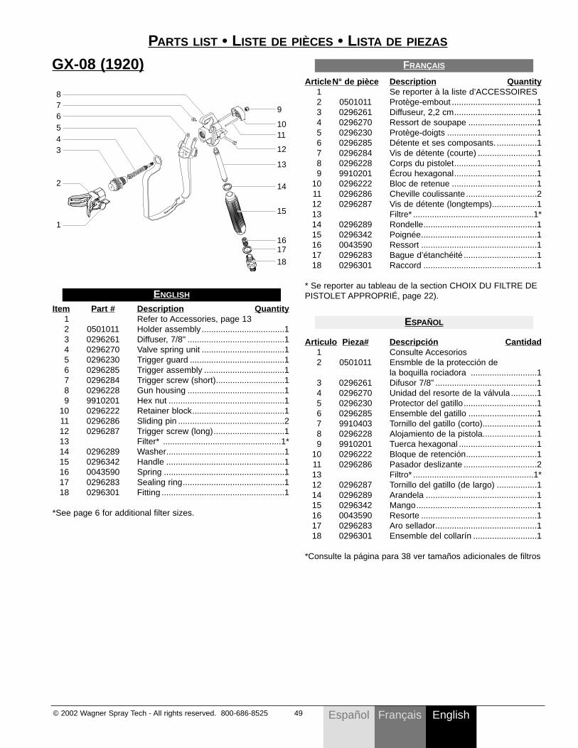
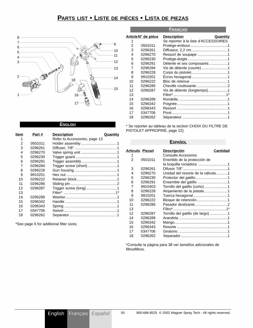
ArticleN° de pièce Description Quantity1 Se reporter à la liste d’ACCESSOIRES2 0501011 Protège-embout ....................................13 0296261 Diffuseur, 2,2 cm...................................14 0296270 Ressort de soupape .............................15 0296230 Protège-doigts ......................................16 0296285 Détente et ses composants. .................17 0296284 Vis de détente (courte) .........................18 0296228 Corps du pistolet...................................19 9910201 Écrou hexagonal...................................1
10 0296222 Bloc de retenue ....................................111 0296286 Cheville coulissante ..............................212 0296287 Vis de détente (longtemps)...................113 Filtre* ...................................................1*14 0296289 Rondelle................................................115 0296342 Poignée.................................................116 0043590 Ressort .................................................117 0296283 Bague d’étanchéité ...............................118 0296301 Raccord ................................................1
* Se reporter au tableau de la section CHOIX DU FILTRE DEPISTOLET APPROPRIÉ, page 22).
Articulo Pieza# Descripción Cantidad1 Consulte Accesorios2 0501011 Ensmble de la protección de
la boquilla rociadora ............................13 0296261 Difusor 7/8” ...........................................14 0296270 Unidad del resorte de la válvula ...........15 0296230 Protector del gatillo...............................16 0296285 Ensemble del gatillo .............................17 9910403 Tornillo del gatillo (corto).......................18 0296228 Alojamiento de la pistola.......................19 9910201 Tuerca hexagonal .................................1
10 0296222 Bloque de retención..............................111 0296286 Pasador deslizante ...............................213 Filtro* ...................................................1*12 0296287 Tornillo del gatillo (de largo) .................114 0296289 Arandela ...............................................115 0296342 Mango...................................................116 0043590 Resorte .................................................117 0296283 Aro sellador...........................................118 0296301 Ensemble del collarín ...........................1
*Consulte la página para 38 ver tamaños adicionales de filtros
ESPAÑOL
FRANÇAIS
PARTS LIST • LISTE DE PIÈCES • LISTA DE PIEZAS
GX-08 (1920)
Item Part # Description Quantity1 Refer to Accessories, page 132 0501011 Holder assembly ...................................13 0296261 Diffuser, 7/8" .........................................14 0296270 Valve spring unit ...................................15 0296230 Trigger guard ........................................16 0296285 Trigger assembly ..................................17 0296284 Trigger screw (short).............................18 0296228 Gun housing .........................................19 9910201 Hex nut .................................................1
10 0296222 Retainer block.......................................111 0296286 Sliding pin .............................................212 0296287 Trigger screw (long)..............................113 Filter* ..................................................1*14 0296289 Washer..................................................115 0296342 Handle ..................................................116 0043590 Spring ...................................................117 0296283 Sealing ring...........................................118 0296301 Fitting ....................................................1
*See page 6 for additional filter sizes.
ENGLISH
876543
2
1
1011
12
13
14
15
1617
18
9
English 50 800-686-8525 © 2002 Wagner Spray Tech - All rights reserved.Français Español
PARTS LIST • LISTE DE PIÈCES • LISTA DE PIEZAS
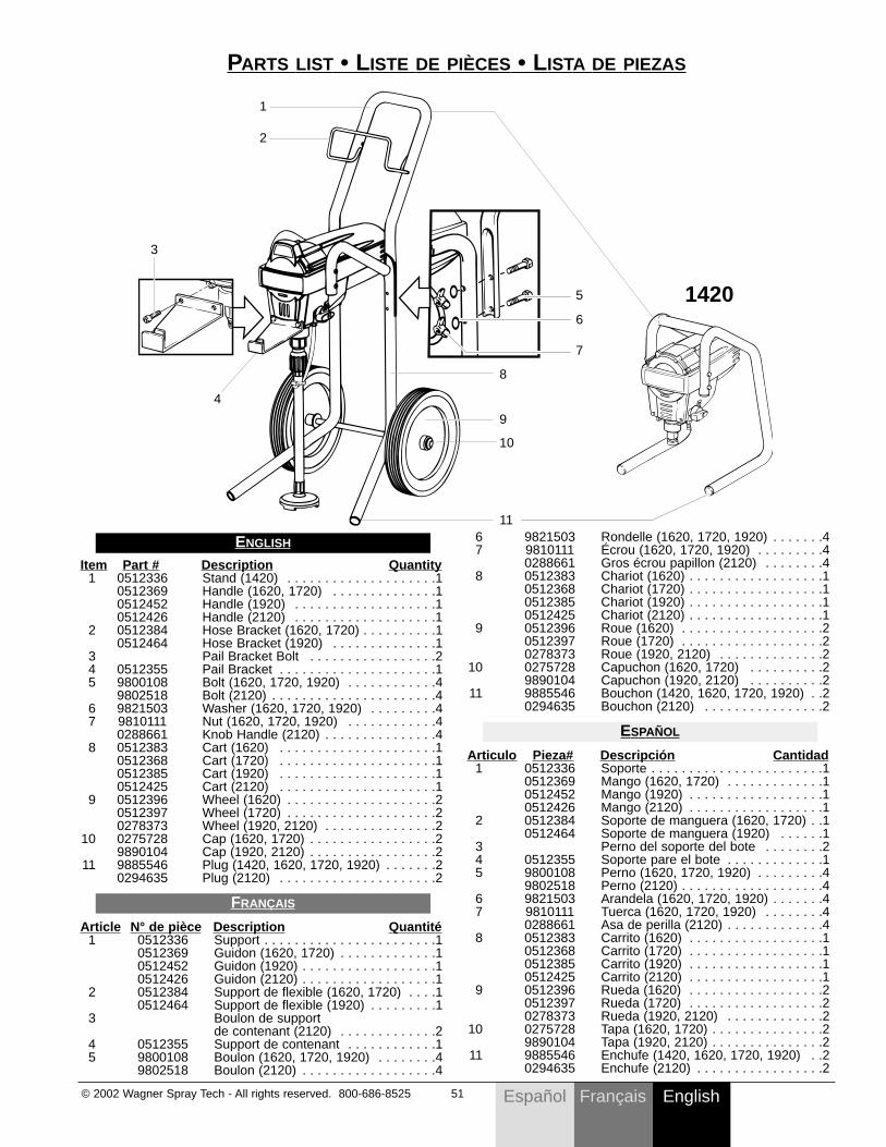
Item Part # Description Quantity1 Refer to Accessories, page 132 0501011 Holder assembly ...................................13 0296261 Diffuser, 7/8" .........................................14 0296270 Valve spring unit ...................................15 0296230 Trigger guard ........................................16 0296291 Trigger assembly ..................................17 0296284 Trigger screw (short).............................18 0296228 Gun housing .........................................19 9910201 Hex nut .................................................1
10 0296222 Retainer block.......................................111 0296286 Sliding pin .............................................212 0296287 Trigger screw (long)..............................113 Filter* ..................................................1*14 0296289 Washer..................................................115 0296342 Handle ..................................................116 0296343 Spring ...................................................117 0347706 Swivel ...................................................118 0296262 Separator ..............................................1
*See page 6 for additional filter sizes.
ENGLISH
876543
2
1
1011
12
13
14
15
9
16
18
17
ArticleN° de pièce Description Quantity1 Se reporter à la liste d’ACCESSOIRES2 0501011 Protège-embout ....................................13 0296261 Diffuseur, 2,2 cm...................................14 0296270 Ressort de soupape .............................15 0296230 Protège-doigts ......................................16 0296291 Détente et ses composants. .................17 0296284 Vis de détente (courte) .........................18 0296228 Corps du pistolet...................................19 9910201 Écrou hexagonal...................................1
10 0296222 Bloc de retenue ....................................111 0296286 Cheville coulissante ..............................212 0296287 Vis de détente (longtemps)...................113 Filtre* ...................................................1*14 0296289 Rondelle................................................115 0296342 Poignée.................................................116 0296343 Ressort .................................................117 0347706 Pivot......................................................118 0296262 Séparateur ............................................1
* Se reporter au tableau de la section CHOIX DU FILTRE DEPISTOLET APPROPRIÉ, page 22).
Articulo Pieza# Descripción Cantidad1 Consulte Accesorios2 0501011 Ensmble de la protección de
la boquilla rociadora ............................13 0296261 Difusor 7/8” ...........................................14 0296270 Unidad del resorte de la válvula ...........15 0296230 Protector del gatillo...............................16 0296291 Ensemble del gatillo .............................17 9910403 Tornillo del gatillo (corto).......................18 0296228 Alojamiento de la pistola.......................19 9910201 Tuerca hexagonal .................................1
10 0296222 Bloque de retención..............................111 0296286 Pasador deslizante ...............................213 Filtro* ...................................................1*12 0296287 Tornillo del gatillo (de largo) .................114 0296289 Arandela ...............................................115 0296342 Mango...................................................116 0296343 Resorte .................................................117 0347706 Giratorio ................................................118 0296262 Separador .............................................1
*Consulte la página para 38 ver tamaños adicionales defiltrosfiltros.
ESPAÑOL
FRANÇAIS
EnglishFrançais© 2002 Wagner Spray Tech - All rights reserved. 800-686-8525 51 Español
6 9821503 Rondelle (1620, 1720, 1920) . . . . . . .47 9810111 Écrou (1620, 1720, 1920) . . . . . . . . .4
0288661 Gros écrou papillon (2120) . . . . . . . .48 0512383 Chariot (1620) . . . . . . . . . . . . . . . . . .1
0512368 Chariot (1720) . . . . . . . . . . . . . . . . . .10512385 Chariot (1920) . . . . . . . . . . . . . . . . . .10512425 Chariot (2120) . . . . . . . . . . . . . . . . . .1
9 0512396 Roue (1620) . . . . . . . . . . . . . . . . . . .20512397 Roue (1720) . . . . . . . . . . . . . . . . . . .20278373 Roue (1920, 2120) . . . . . . . . . . . . . .2
10 0275728 Capuchon (1620, 1720) . . . . . . . . . .29890104 Capuchon (1920, 2120) . . . . . . . . . .2
11 9885546 Bouchon (1420, 1620, 1720, 1920) . .20294635 Bouchon (2120) . . . . . . . . . . . . . . . .2
Articulo Pieza# Descripción Cantidad1 0512336 Soporte . . . . . . . . . . . . . . . . . . . . . . .1
0512369 Mango (1620, 1720) . . . . . . . . . . . . .10512452 Mango (1920) . . . . . . . . . . . . . . . . . .10512426 Mango (2120) . . . . . . . . . . . . . . . . . .1
2 0512384 Soporte de manguera (1620, 1720) . .10512464 Soporte de manguera (1920) . . . . . .1
3 Perno del soporte del bote . . . . . . . .24 0512355 Soporte pare el bote . . . . . . . . . . . . .15 9800108 Perno (1620, 1720, 1920) . . . . . . . . .4
9802518 Perno (2120) . . . . . . . . . . . . . . . . . . .46 9821503 Arandela (1620, 1720, 1920) . . . . . . .47 9810111 Tuerca (1620, 1720, 1920) . . . . . . . .4
0288661 Asa de perilla (2120) . . . . . . . . . . . . .48 0512383 Carrito (1620) . . . . . . . . . . . . . . . . . .1
0512368 Carrito (1720) . . . . . . . . . . . . . . . . . .10512385 Carrito (1920) . . . . . . . . . . . . . . . . . .10512425 Carrito (2120) . . . . . . . . . . . . . . . . . .1
9 0512396 Rueda (1620) . . . . . . . . . . . . . . . . . .20512397 Rueda (1720) . . . . . . . . . . . . . . . . . .20278373 Rueda (1920, 2120) . . . . . . . . . . . . .2
10 0275728 Tapa (1620, 1720) . . . . . . . . . . . . . . .29890104 Tapa (1920, 2120) . . . . . . . . . . . . . . .2
11 9885546 Enchufe (1420, 1620, 1720, 1920) . .20294635 Enchufe (2120) . . . . . . . . . . . . . . . . .2
ESPAÑOL
PARTS LIST • LISTE DE PIÈCES • LISTA DE PIEZAS
Item Part # Description Quantity1 0512336 Stand (1420) . . . . . . . . . . . . . . . . . . . .1
0512369 Handle (1620, 1720) . . . . . . . . . . . . . .10512452 Handle (1920) . . . . . . . . . . . . . . . . . . .10512426 Handle (2120) . . . . . . . . . . . . . . . . . . .1
2 0512384 Hose Bracket (1620, 1720) . . . . . . . . . .10512464 Hose Bracket (1920) . . . . . . . . . . . . . .1
3 Pail Bracket Bolt . . . . . . . . . . . . . . . . .24 0512355 Pail Bracket . . . . . . . . . . . . . . . . . . . . .15 9800108 Bolt (1620, 1720, 1920) . . . . . . . . . . . .4
9802518 Bolt (2120) . . . . . . . . . . . . . . . . . . . . . .46 9821503 Washer (1620, 1720, 1920) . . . . . . . . .47 9810111 Nut (1620, 1720, 1920) . . . . . . . . . . . .4
0288661 Knob Handle (2120) . . . . . . . . . . . . . . .48 0512383 Cart (1620) . . . . . . . . . . . . . . . . . . . . .1
0512368 Cart (1720) . . . . . . . . . . . . . . . . . . . . .10512385 Cart (1920) . . . . . . . . . . . . . . . . . . . . .10512425 Cart (2120) . . . . . . . . . . . . . . . . . . . . .1
9 0512396 Wheel (1620) . . . . . . . . . . . . . . . . . . . .20512397 Wheel (1720) . . . . . . . . . . . . . . . . . . . .20278373 Wheel (1920, 2120) . . . . . . . . . . . . . . .2
10 0275728 Cap (1620, 1720) . . . . . . . . . . . . . . . . .29890104 Cap (1920, 2120) . . . . . . . . . . . . . . . . .2
11 9885546 Plug (1420, 1620, 1720, 1920) . . . . . . .20294635 Plug (2120) . . . . . . . . . . . . . . . . . . . . .2
Article N° de pièce Description Quantité1 0512336 Support . . . . . . . . . . . . . . . . . . . . . . .1
0512369 Guidon (1620, 1720) . . . . . . . . . . . . .10512452 Guidon (1920) . . . . . . . . . . . . . . . . . .10512426 Guidon (2120) . . . . . . . . . . . . . . . . . .1
2 0512384 Support de flexible (1620, 1720) . . . .10512464 Support de flexible (1920) . . . . . . . . .1
3 Boulon de support de contenant (2120) . . . . . . . . . . . . .2
4 0512355 Support de contenant . . . . . . . . . . . .15 9800108 Boulon (1620, 1720, 1920) . . . . . . . .4
9802518 Boulon (2120) . . . . . . . . . . . . . . . . . .4
FRANÇAIS
ENGLISH
10
11
9
8
5
6
7
2
4
1
3
1420

English 52 800-686-8525 © 2002 Wagner Spray Tech - All rights reserved.Français Español
GARANTIE LIMITÉEMATÉRIEL DE PULVÉRISATION DE PEINTURE SANS AIR
Ce produit, fabriqué par Wagner Spray Tech Corporation (Wagner), est garanti, au bénéfice de l’acheteur au détail d’origine, contre tout vice de matières et toutemalfaçon pour un an à compter de la date d’achat.
La présente garantie ne s'applique pas aux dégâts entraînés par une utilisation incorrecte, par la négligence de l'usager ou par l'usure normale. La présente garantiene s'applique pas non plus aux défectuosités ou dommages résultant de l'entretien ou de la réparation que fait une personne quelconque qui ne soit pas membred'un centre d'entretien autorisé pour les produits Wagner. La présente garantie ne s'applique pas aux accessoires.
TOUTE GARANTIE IMPLICITE DE QUALITÉ MARCHANDE OU D'ADAPTATION À UN USAGE PARTICULIER EST LIMITÉE À UNE PÉRIODE DE 30 JOURSPOUR UNE UTILISATION PROFESSIONNELLE OU DE LOCATION ET D'UNE ANNÉE POUR L'UTILISATION DOMESTIQUE, À COMPTER DE LA DATED'ACHAT.
TOUTE GARANTIE IMPLICITE DE VENDABILITÉ OU DE CONVENANCE À UNE DESTINATION PARTICULIÈRE EST LIMITÉE À UN AN À COMPTER DE LADATE D’ACHAT.
Si un produit est défectueux en ce qui concerne les matériaux ou l'exécution pendant la période de garantie applicable, vous devez le retourner, avec une preuved'achat et frais de port payés, à n'importe quel centre d'entretien autorisé pour les produits Wagner. (Une liste de ces centres d'entretien est jointe à ce produit.)Le centre d'entretien autorisé pour les produits Wagner réparera ou remplacera le produit (à la discrétion de Wagner) et vous le retournera par la poste, avecfrais de port payés.
CERTAINES PROVINCES INTERDISENT LES RESTRICTIONS SUR LA DURÉE D'UNE GARANTIE IMPLICITE OU L'EXCLUSION DES DOMMAGESACCESSOIRES OU INDIRECTS. IL SE PEUT DONC QUE LA RESTRICTION ET L'EXCLUSION ÉNONCÉES CI-DESSUS NE S'APPLIQUENT PAS À VOUS.LE PRÉSENTE GARANTIE VOUS ACCORDE DES DROITS JURIDIQUES SPÉCIFIQUES, ET VOUS AVEZ PEUT-ÊTRE D'AUTRES DROITS, QUI PEUVENTVARIER D'UNE PROVINCE À L'AUTRE.
Wagner Spray Tech Corporation1770 Fernbrook LaneMinneapolis, Minnesota 55447Telephone 1-800-686-8525
LIMITED WARRANTYAIRLESS PAINT SPRAY EQUIPMENT
This product, manufactured by Wagner Spray Tech Corporation (Wagner), is warranted to the original retail purchaser against defects in material and workmanshipfor one year from date of purchase.
This warranty does not cover damage resulting from improper use, accidents, user's negligence or normal wear. This warranty does not cover any defects ordamages caused by service or repair performed by anyone other than a Wagner Authorized Service Center. This warranty does not apply to accessories.
ANY IMPLIED WARRANTY OF MERCHANTABILITY OR FITNESS FOR A PARTICULAR PURPOSE IS LIMITED TO ONE YEAR FROM DATE OF PURCHASE.
WAGNER SHALL NOT IN ANY EVENT BE LIABLE FOR ANY INCIDENTAL OR CONSEQUENTIAL DAMAGES OF ANY KIND, WHETHER FROM BREACH OFTHIS WARRANTY OR ANY OTHER REASON.
If any product is defective in material and/or workmanship during the applicable warranty period, return it with proof of purchase, transportation prepaid to anyWagner Authorized Service Center. (Service Center listing is enclosed with this product.) Wagner’s Authorized Service Center will either repair or replace the product(at Wagner’s option) and return it to you, postage prepaid.
SOME STATES DO NOT ALLOW LIMITATIONS ON HOW LONG AN IMPLIED WARRANTY LASTS OR THE EXCLUSION OF INCIDENTAL ORCONSEQUENTIAL DAMAGES, SO THE ABOVE LIMITATION AND EXCLUSION MAY NOT APPLY TO YOU.
THIS WARRANTY GIVES YOU SPECIFIC LEGAL RIGHTS, AND YOU MAY ALSO HAVE OTHER RIGHTS WHICH VARY FROM STATE TO STATE.
GARANTÍA LIMITADAEQUIPO DE ATOMIZACIÓN DE PINTURA SIN AIRE
Este producto, fabricado por Wagner Spray Tech Corporation (Wagner), está garantizado ante el comprador original contra defectos de materiales y mano de obradurante un año contado a partir de la fecha de compra.
Esta garantía no cubre los daños que sean resultado de un uso inapropiado, accidentes, negligencia del usuario o un desgaste normal. Esta garantía no cubreningún defecto o daño que haya sido causado por los servicios o reparaciones llevadas a cabo por alguien que no sea un técnico del Centro de Servicio Autorizadode Wagner. Esta garantía no es válida para ningún accesorio.
CUALQUIER GARANTIA IMPLICITA DE COMERCIALIZACION O IDONEIDAD PARA CUALQUIER PROPOSITO EN PARTICULAR QUEDA LIMITADA A UN AÑOA PARTIR DE LA FECHA DE COMPRA.
WAGNER NO SERÁ EN NINGÚN CASO RESPONSABLE DE NINGÚN DAÑO INCIDENTAL O DE CONSECUENCIA DE NINGUNA CLASE, QUE RESULTE DEVIOLAR ESTA GARANTÍA O POR CUALQUIER OTRA RAZÓN.
Si algún producto llegara a tener defectos de material y/o mano de obra durante el período de validez de la garantía, devuélvalo junto con el comprobante de compray flete previamente pagado, a cualquier Centro de Servicio Autorizado de Wagner. (La lista de Centros de Servicio viene adjunta con este producto.) El Centro deServicio Autorizado de Wagner reparará o reemplazará el producto (según la opción de Wagner) y se lo devolverá, con porte previamente pagado.
ALGUNOS ESTADOS NO PERMITEN LIMITACIONES EN CUANTO A LA DURACIÓN DE UNA GARANTÍA IMPLÍCITA O LA EXCLUSIÓN DE DAÑOSINCIDENTALES O DE CONSECUENCIA, DE MANERA QUE LA LIMITACIÓN Y EXCLUSIÓN ANTERIORES PODRÍAN NO SER VÁLIDAS PARA USTED.ESTA GARANTÍA LE CONCEDE DERECHOS LEGALES ESPECÍFICOS, PERO USTED PODRÍA TENER DERECHO A OTROS, LOS CUALES VARÍAN DE UNESTADO A OTRO.
Copyright © 2002 Wagner Spray Tech Corporation.All rights reserved, including right of reproduction in
whole or in part, in any form. Printed in U.S.A.


![1720 [Compatibility Mode]](https://img.pdfslide.us/doc/110x75/577c823b1a28abe054affe12/1720-compatibility-mode.jpg)