Embed Size (px)
Citation preview
PNEUMATIC STANDARDSfor
INDUSTRIALEQUIPMENT
andGENERAL PURPOSE
MACHINE TOOLSP-1-1975
FOREWORDUsers and suppliers of industrial equipment, as well as the
component manufacturers, have long recognized that the safety of personnel and uninterrupted production are of cardinal importance to the economic growth of industry. The application of pneumatics to industrial equipment resulted in preparation of the first pneumatic standard over 20 years ago. This is the latest revision of that standard.
This revision has been written as a General Purpose Pneumatic Standard and has been extended, where noted, to Mass Production Equipment, as well as to the type of engineering considered desirable. This standard is basic in nature, that is, it does not contain any requirements specific to any one industry, company, division, or plant.
All JIC standards are advisory only. Their use in industry or trade is entirely voluntary.
The JIC assumes no liability for any patent infringements or asserted patent infringements which may result from the use of this standard.
Comments or requests for information regarding JIC activities or interpretation of the JIC standards should be addressed to the Secretary of the Joint Industrial Council, 7901 Westpark Drive, McLean, VA 22101.
Proposals to change this JIC Pneumatic Standard are considered in the Joint Industrial Council meetings held at intervals for this purpose. Future revisions will include application requirements for those fields that become so closely associated with the pneumatic science as to be deemed a part thereof. No additions, revisions, or deletions shall be made hereto when reproduced as the JIC Pneumatic Standard for Industrial Equipment.
The JIC Pneumatic Standard Committee which prepared this standard was composed of:
T.F. Graffy - Chairman
Airmatic/Beckett-Harcum
W.A. Burton
Lawrence Livermore Laboratory
C.A. Cross
Ford Motor Company
W.F. Diehl
General Motors Corporation
R.D. Forney
Cincinnati Milacron Inc.
J.P Jenny
Aluminum Company of America
H.R. Kutcher
Aluminum Company of America
A.J. McClelland
The Warner & Swanery Company
W.T. McCormick
Caterpillar Tractor Company
B. MacGregor
General Motors Corporation
R. Muhl
National Automatic Tool Company
J.A Neff
Mac Air Valve Company
J.J. Pippenger
W.H. Nichols Company
M. Swirski
Sperry Vickers Division
V.R. Walser
Giddings & Lewis Machine Tool Company

INDEXP1 GENERAL ............................................. ...............1P1.1 Purpose ............................................. ...............1P1.2 Scope ............................................. ...............1P1.3 Reference Documents.......................... ...............1P1.4 Dual Purpose Standard ................................. ......1P1.5 Specific Requirement Version ................. ...........1P1.6 Type of Requirements........................... ..............1P1.7 Deviations................................................... ........1P1.8 Definitions ........................................ .................1P1.9 Data Form................................................ ...........1
P1.9.1 Data Form UseP1.9.2 Data Form ContentP1.9.3 Omitted InformationP1.9.4 Data Form Revision
P1.10 Drawings ......................................................... ...1P1. 10.1 Graphical DiagramP1.10.2 Floor LayoutP1.10.3 Piping Layout
P1.11 Data to Supplier ................................ ................2 P1.11.1 Scope of Data to Supplier
P1.12 Data to Purchaser ................................................. ....2P1.12.1 Preliminary DataP1.12.2 Final DataP1.12.3 Field changesP1.124 Maintenance Data
P1.13 Procurement of Components ...................... ........2P1.14 Design Requirements ............................. ............2P1.15 Minimum Operating and Maximum
Allowable Pressure .......................... ..................2P1.16 Installation and Use ......................................... ..2 P1.17 Safety ............................................. ...............3
P1.17.1 Fail-Safe ConceptP1.17.2 Service with SafetyP1.17.3 Inclined LaddersP1.1 7.4 Elevated PlatformsP1. 17.5 Exhaust Protection
P1.18 Accessibility ................................. .....................3P1.19 Identification ................................................ ......3
P1.19.1 Manufacturer s Information PlatesP1.19.2 Component IdentificationP1.19.3 Port IdentificationP1.19.4 Valve Operator IdentificationP1.19.5 Identification of Internal DevicesP1.19.6 Location of IdentificationP1.19.7 Control Station Information PlatesP1.19.8 Identification Plate/Tag Material
P 1.20 Final Tests..................................................... ........3P1.20.1 Performance TestsP1.20.2 LeakageP1.20.3 Noise Limit
P1.21 Preparation for Shipment ................. ..................3P1.21.1 Identification of PipingP1.21.2 Packaging of PipingP1.21.3 Sealing of Openings
P2 CIRCUIT CONTROLS ................................... ........3P2.1 Definition of Controls ........................... .............3
P2.1.1 Manual Control
P2.1.2 Automatic ControlP2.2 Pressure Regulation ...................... .....................3P2.3 Protection ..................................................... ......4
P2.3.1 Over-Pressure ProtectionP2.3.2 Tamper-Resistant ProtectionP2.3.3 Safe Working Range of Adjustable
ControlsP2.3.4 Accessibility of AdjustmentsP2.3.5 Securing Adjustable Component
SettingsP2.3.6 Locking of Adjustable Component
SettingsP2.3. 7 Loss of Working PressureP2.3.8 Control Media FailureP2.3.9 Control of Multiple DevicesP2.3.10 Supply Shut-Off ValveP2.3.11 Supply Interlocks
P2.4 Manual Controls ........................... .....................4P2.4.1 Control Station Information Plate(s)P2.4.2 Emergency Controls
P2.4.2.1 Emergency Stop and ReturnControl
P2.4.2.2 Emergency Stop and Return Con-trol Features
P2.4.2.3 Emergency ControlsP2.4.2.4 Cycle Restart
P2.4.3 Manual Control ActuatorsP2.4.4 Set- Up ControlsP2.4.5 Two-Hand ControlP2.4.6 Location of Manual Controls
P2.5 Automatic Controls .................................... ........5P2.5.1 Location of Automatic ControlsP2.5.2 Surge PressuresP2.5.3 Sequence Control P2.5.3.1 Sequence by Position
P2.5.3.2 Sequence by Pressure Sensing andTime response
P2.5.4 Uncontrolled MovementP2.5.5 Dwell TimeP2.5.6 Energy Absorption
P2.6 Circuit Relationships ...................................... ....5P2.6.1 OperationP2.6.2 Load
P2.7 Enclosures and Compartments ............... ............5P2.7.1 MaterialsP2.7.2 Types of Doors and CoversP2. 7.3 Maintenance Access
P3 LINEAR ACTUATORS (CYLINDERS)AND ROTARY ACTUATORS ........................ ........5
P3.1 Actuator Specifications .......................... ............5P3.2 Actuator Alignment ......................................... ...5
P3.2.1 Rigid MountingsP3.2.2 Non-Rigid Mountings
P3.3 Actuator Servicing .............................. ...............5P3.4 Actuator Replacement .................................. ......5P3.5 Required Cushions ................................... ..........5P3.6 Actuator Seals and Sealing Devices ...................6
P3.6.1 Seal Requirements
JIC Pneumatic Standards i
P3.6.2 Actuator Seals P3.6.3 Piston Rod Seal Replacement
P3.7 Actuator Rods ...................................... ..............6P3.7.1 Actuator Rod SizeP3.7.2 Piston and Rod AssemblyP3.7.3 Actuator Rod HardnessP3.7.4 Protection of Actuator Rods
P3.8 Manufacturer’s Information ................. ..............6P4 ROTARY AIR MOTORS
(CONTINUOUS ROTATION) ......................... .......6P4.1 Manufacturer s Information ...............................6
P4.1.1 Information Plate DataP4.1.2 Duplicate InformationP4.1.3 Data Sheets
P4.2 Air Supply Conditions .................. .....................6P4.3 Protection of Rotary Motors ............................. ..6P4.4 Couplings ..................................................... ......6
P4.4.1 Coupling Type and AlignmentP4.4.2 Coupling Fitting ProcedureP4.4.3 Coupling GuardsP4.4.4 Power TransmissionP4.4.5 Coupling Accessibility
P4.5 Mounting ...................................... .....................6P4.6 Accessibility ................................. .....................6P4.7 Side Loads ...................................... ...................6P4.8 Load Considerations ....................... ...................6P4.9 Direction of Motor Rotation ............................. ..6P5 COMPRESSORS ............................................ .........6P5.1 Compressor Data ............................................... .6
P5.1.1 Data SheetsP5.1.2 Information PlateP5.1.3 Duplicate Information PlateP5.1.4 Direction of Rotation
P5.2 Installation ........................................ .................7P5.3 Mounting ...................................... .....................7
P5.3.1 Rigid MountingP5.3.2 Common Sub-BaseP5.3.3 Direct Coupled UnitsP5.3.4 Belt Drives
P5.4 Couplings ..................................................... ......7P5.4.1 Coupling Type and Alignment:P5.4.2 Coupling Fitting ProcedureP5.4.3 Power TransmissionP5.4.4 Coupling Guards
P5.5 Compressor Intake .............................. ...............7P5.5.1 Inlet ConditionsP5.5.2 Inlet Filters
P5.6 Emergency Pressure Relief ............. ...................7P5.7 Parallel Installations .................................... .......7P6 RECEIVERS, SURGE TANKS. AND
AIR BOTTLES ....................................... .................7P6.1 Definitions ........................................ .................7
P6.1.1 Receivers.......................................... .....P6.1.2 Surge TanksP6.1.3 Air Bottles
P6.2 Design ............................................. ...............7P6.2.1 Air Receivers and Surge Tanks
P6.2.1.1 Design Working Pressure
P6.2.1.2 Air Line PressureP6.2.1.3 Construction
P6.2.2 Air BottlesP6.2.2.1 Design Working PressureP6.2.2.2 ConstructionP6.2.2.3 Air Bottle Equipment
P6.3 Sizing ............................................. ...............8P6.3.1 Volume of Air ReceiversP6.3.2 Volume of Surge TanksP6.3.3 Air Bottle Size and Weight
P6.4 Pressure Vessel Data ....................... ...................8P6.4.1 Manufacturer’s Information
P6.5 Installation........................................ ................. 8P6.5.1 Receivers and Surge TanksP6.5.2 Air Bottles
P7 FLUID CONDITIONING .......................... .............8P7.1 Removal of Foreign Materials............................ .8P7.2 Cleaning and Draining ....................... ................8P7.3 Filter-Separator Locution ....................... ............8P7.4 Automatic Drains ...................................... .........8P7.5 Filter Elements ............................................ .......8P7.6 Lubricator Location .................... ......................8P7.7 Lubricator Filling .................................... ..........8P7.8 Lubricator Drains .................................... ..........8P7.9 Positive Injection Type Lubricators ............... ....8P7.10 Protection .................................................... ......8P8 VALVING ............................................. ...............9P8.1 Manifold. Mounted Valves ......................... ........9
P8.1.1 MountingP8.1.2 AssemblyP8.1.3 Leak DetectionP8.1.4 Back Pressure Protection
P8.2 Electrically Operated Valves ............... ...............9P8.2.1 Solenoid Valve Features
P8.3 Port and Lead identification .................. .............9P8.4 Valve Application .......................................... .....9
P8.4.1 Mounting ConsiderationsP8.4.1.1 Spool-Type ValvesP8.4.1.2 Spring Returned Valves
P8.4.2 Detented ValvesP8.4.3 Required Two-Position ValvesP8.4.4 Counterbalancing
P9 PIPING FITTINGS, ANDFLUID PASSAGES ................................................ ..9
P9.1 Piping Definition ............................................... .9P9.1.1 PipingP9.1.2 Passage
P9.2 Piping Layout .................................................... .9P9.3 External Piping Identification ............................9P9.4 Fluid Velocity in Piping ................ .....................9P9.5 Conductor Contained Volume ............................9P9.6 Foreign Matter in Piping ........................ ............9P9.7 Test Ports ....................................... ....................9
P9.7.1 Test Ports in PipingP9.7.2 Test Port Indication
P9.8 Wall Strength of Piping ........................... .........10P9.9 Pressure Ratings ........................................... ....10
P9.9.1 Rigid Conductors
JIC Pneumatic Standards ii
P9.9.2 Flexible LinesP9.10 Pipe Specifications..................................... ...... 10P9.11 Tubing .......................................... ................10
P9.11.1 Steel Tubing SpecificationsP9.11.2 Plastic TubingP9.11.3 Tubing Sizes
P9.12 Piping Connections ............................ ..............10P9.12.1 Flared FittingsP9.12.2 S traight Thread Ports and FittingsP9.12.3 Taper Pipe ThreadsP9.12.4 AssemblyP9.12.5 S tepped Passages
P9.13 Piping Runs ................................................... ...10P9.13.1 Continuous Tubing RunsP9.13.2 Tube BranchingP9.13.3 Number of Fittings
P9.14 Piping A cross Access Ways ................... ..........10P9.15 Piping Between Assemblies ............. ................10P9.16 Piping Locations ............................. .................10P9.17 Piping Supports .......................................... ......10
P9.17.1 Support RequirementsP9.17.2 Support InstallationsP9.17.3 Spacing of Piping Supports
P9.18 Accessibility of Piping......................... ............ 10P9.18.1 Accessibility of Piping Connections P9.18.2 Clearances in Fitting Clusters P9.18.3 Removal of Piping Runs
P9.19 Flexible Lines .................................................. .11P9.19.1 Flexible Line UseP9.19.2 Flexible Hose InstallationsP9.19.3 Flexible Hose ReplacementP9.19.4 Vibration and/or Noise Suppression P9.19.5 Hose Specifications
P9.20 Fluid Conducting Manifolds ............................11P9.20.1 Manifold DefinitionP9.20.2 Mounting ManifoldP9.20.3 Junction ManifoldP9.20.4 Terminal ManifoldP.20.5 Circuit Manifold
P9.20.5.1 Circuitry within ManifoldsP9.20.5.2 Identification on Circuit ManifoldsP9.20.5.3 Internal DevicesP9.20.5.4 Manifold Assemblies P9.20.6 Manifold Distortion
P9.20.7 Manifold MaterialsP9.20.8 Flow Capacity of Man ifold ConductorsP9.20.9 Handling ProvisionsP9.20.10 Support of Manifolds
P10 SEALS AND SEALING DEVICES ......................11P10.1 Sealing Principles ......................................... ....11P10.2 Sealing Materials.............................................. .11P10.3 Availability...................................................... ..11P10.4 Seal Replacement..................................... .........11P10.5 Seal Gland Clearances..................................... ..11P10.6 Adjustable Seal Glands................... ..................11P11 SAFETY .......................................... ................12P11.1 Fail Safe Concept..................................... ........ 12P11.2 Service with Safety......................... ................. 12
P11.3 Inclined Ladders ....................... .......................12P11.4 Elevated Platforms ................................ ...........12P11.5 Noise Limit ......................................... .............12P11.6 Pressure Regulation.................... ......................12P11.7 Over Pressure Protection ............................ ......12P11.8 Tamper-Resistant Protection ............................12P11.9 Safe Working Range of
Adjustable Controls ................... ......................12P11.10 Securing Adjustable Component Settings ........12P11.11 Loss of Working Pressure ................................. 12P11.12 Control Media Failure..................................... ..... 12P11.13 Control of Multiple Devices.................................12P11.14 Supply Shut-Off Valve ...................... ...............12P11.15 Supply Interlocks .............................. ...............12P11.16 Emergency Controls ..................................... ....12
P11.16.1 Emergency Stop and Return Control P11.16.2 Emergency Stop and Return Control
FeaturesP11.16.3 Emergency ControlsP11.16.4 Cycle Restart
P11.17 Two-Hand Control ......................... ..................13P11.18 Locations of Manual Controls ................... .......13P11.19 Surge Pressures ................................... .............13P11.20 Sequence by Position ....................... ................13P11.21 Sequence by Pressure Sensing
and Time Lapse ....................................... .........13P11.22 Uncontrolled Movement ................ ..................13P11.23 Direction of Motor Rotation .......................... ...13P11.24 Belt Drives ............................................. ..........13P11.25 Emergency Pressure Relief ..............................13P11.26 Air Receiver and Surge
Tank Construction .................................. ..........13P11.27 Receivers and Surge Tanks ............................. ..13P11.28 Air Bottle Construction .......................... ..........13P11.29 Air Bottle Equipment ............................ ...........13P11.30 Air Bottles ...................................................... ..13P11.31. Protection .................................................. .......13P11.32 Solenoid Valve Features ......................... ..........14P11.33 Valve Application ....................................... ......14
P11.33.1 Mounting ConsiderationsP11.33.1.1 Spool-Type ValvesP11.33.1.2 Spring-Returned ValvesP11.33.2 Detented ValvesP11.33.3 Required Two-Position ValvesP11.33.4 Counterbalancing
P11.34 Flexible Line Use ..................................... ........14P11.35 Exhaust Protection ......................... .................14TABLE I - Spacing of Piping Supports.............10APPENDIX A - Sample Graphic Diagram 1 5APPENDIX B - Recommended Tubing Sizes and
Flow Rates for Use in Air Circuits0. 125 PSIG. Schedule 40 Pipe andSteel Tubing .................. ...................16
APPENDIX C — Tubing Diameter and Wall Thick-ness. Copper Tubing................ ..........16
APPENDIX D - Standard Reference Documents.....17APPENDIX E - JIC Pneumatic Equipment Data
Form for Mass ProductionEquipment........................... ............. 18
JIC Pneumatic Standards iii

P1 GENERALP1.1 Purpose. The purpose of this standard is to provide guidelines for industrial equipment manufacturers and users of pneumatic apparatus to promote:
(1) Safety of personnel..(2) Uninterrupted production.(3) Long life of equipment.(4) Ease and economy of maintenance.
This standard is intended as a reference and guide for detailed specifications and designs for industrial equipment utilizing pneumatic components or equipment.P1.2 Scope. This standard applies to all pneumatic applications on industrial equipment. Industrial equipment. for the purpose of this document, is any equipment pneumatically actuated or controlled, used in or necessary for manufacturing processes and/or assembly.P1.3 Reference Documents. To avoid duplication of effort and conflict, standards developed by other technical organizations have been referenced and adopted as part of this JIC standard. See Appendix D for a bibliography of the referenced and adopted standards and their source of supply.P1.4 Dual Purpose Standard. This revision of the J IC Pneumatic Standard for Industrial Equipment is a dual purpose standard. It is written as a General Purpose Standard and extended, where noted, to Mass Production Equipment.
Indicates a specific requirement for JIC Mass Production Equipment only.
Mass Production Equipment is single and/or special purpose equipment for continuous manufacturing processing and assembly.P1.5 Specific Requirement Version. Where the purchaser specifies conformance to this JIC standard and fails, to specify either the General Purpose or the Mass Production version, the General Purpose Pneumatic Standard shall apply.P1.6 Type of Requirements. Mandatory requirements of this standard are distinguished by use of the word “shall”.Recommendations in this standard are distinguished by use of the word “should”.
Indicates type of engineering desirable in new developments and re-engineering of equipment.
P1.7 Deviations. Deviation(s) from this standard shall be agreed to in writing by the purchaser and supplier. Deviation(s) by the purchaser shall be specified on his purchase inquiry, or the Pneumatic Equipment Data Form, and be confirmed on the supplier’s quotation. Deviation(s) by the supplier shall be listed as “JIC Deviation by (firm name)” on supplier’s quotation and be confirmed in the purchase order. Deviation(s) shall pertain to specific paragraphs of this standard, shall apply to the order in question and not to future orders, and shall not be considered as permanent amendments to this standard. Inclusion of any recommendations as mandatory shall be by written agreement between the purchaser and supplier.P1.8 Definitions. Definitions of the terms used in this standard are those given in ANS B93.2-1971, Glossary of Terms for Fluid Power.
■ P1.9 Data Form.■ P1.9.1 Data Form Use. A sample Pneumatic Equipment
Data Form is provided in Appendix E. This data form, or a similar document, should be used by the purchaser to provide the supplier with information required for the proper and specific pneumatic application to mass production industrial equipment. Where a data form or similar document is used by the purchaser, it shall be confirmed on the supplier’s quotation.
■P1.9.2 Data Form Content. The purchaser of mass production equipment should clearly indicate on the data form or similar document:
(1) To which version of this standard, supplement(s) and/or other standards, if any, he requires conformance.
(2) Unusual operating conditions, environmental conditions not otherwise provided for, and required deviation(s) from this standard, as special requirements.
(3) Unique and other special requirements not covered in part (2) of this paragraph.
(4) Reference to applicable state and local codes.(5) His equipment preference and the order of preference.■P1. 9.3 Omitted Information. Where the purchaser of mass
production equipment does not indicate on the data form or similar document:
(1) Conformance to any particular standard(s), the supplier’s standard shall be acceptable.
(2) His equipment preference, the supplier’s choice of equipment shall be acceptable.
(3) The order of equipment preference, the supplier’s choice from the purchaser’s preferred equipment list shall be acceptable.
■ P1. 9.4 Data Form Revision. Where a Pneumatic Equipment Data Form or similar document is used and later agreements between the purchaser and supplier negate data in the existing data document, the purchaser shall issue a corrected Pneumatic Equipment Data Form or similar data document. The document shall be marked “Revised” and shall be dated. The revised data form or similar document shall be confirmed by the supplier.P1.10 Drawings.
P1.10.1 Graphical Diagram. ANS Y32.lO.l967 (R1974), Graphic Symbols for Fluid Power Diagrams, shall be used for graphical (circuit) diagrams and to indicate component function. In final graphical diagrams, full symbols, not a simplified form, shall be used for multiple flow path directional valves. Information conveyed on and the arrangement of the graphical diagrams shall be in accordance with ANS Y14.17-l966 (R1974), Fluid Power Diagrams, and Shall include the following:
(1) Identification of all pneumatic equipment by name, catalog number, serial number and/or model number (if it fully describes the component), and the manufacturer’s name.
(2) Type and size of piping (outside diameter and wall thickness of tubing, size and schedule of pipe, inside diameter and SAE type of hose).
(3) Diameter of each cylinder piston and rod, length of stroke and the estimated force required for the intended service.
(4) The RPM, delivery in SCFM. and the directionof rotation of each compressor. if part of the equipment.
(5) The horsepower. RPM. and type of each integral compressor drive, if part of the equipment.
(6) Operating pressure for the intended service and maximum rated pressure.
(7) Non-integral air supply pressure and delivery in(1) SCFM.
(8) Time cycle, e.g., time range of cycle exclusive of loading.
(9) Data or text, or both, showing operations performed with rated electrical and mechanical control and actuating equipment.
(10) Total air consumption in SCFM at each external air connection.
(11) Fluid conditioning requirements. A sample graphical diagram is shown in Appendix A.
P1. 10.2 Floor Layout. Where the installation consists of two or more separated equipment assemblies, the supplier shall provide the purchaser with a floor plan layout, specifying dimensional relationships.
P1.10.3 Piping Layout. Where requested on the purchaser’s inquiry and confirmed on the supplier’s quotation, a piping layout shall be furnished by the supplier. Photographs which clearly show the piping arrangement and assembly may be substituted by agreement. (Ref. P9.2)P1.11 Data to Supplier.
P1.11.1 Scope of Data to Supplier. The purchaser shall specify on his inquiry, or on the Pneumatic Equipment Data Form, and the supplier shall confirm on his quotation, all the information required for proper application and maintenance of production equipment. Such information shall include:
(1) Available utilities.(2) Unusual operating conditions.(3) Special requirements and unusual environmental
conditions.(4) Required deviations from this standard.(5) Reference to applicable state and local codes.(6) Ambient temperature range of the installation.(7) Altitude of installations above 3300 feet (I km).
P1.12 Data to Purchaser.P1.12.1 Preliminary Data. Unless the purchaser indicates
otherwise, the supplier shall submit, for the purchaser’s approval, preliminary performance data on the pneumatic equipment including diagrams in accordance with ANS Y32.10.l967 (Rl974), Graphic Symbols for Fluid Power Diagrams, and ANS Y14.l7-l966 (R1974), Fluid Power Diagrams.
P1.12.2 Final Data. Final diagrams, drawings, and texts, including the maintenance data, shall conform to the equipment as finally accepted. Final graphical (circuit) diagram(s) shall clearly show all fluid conductors within circuit manifolds accommodating two or more manifold mounted components. Where requested on the purchase order, or the Pneumatic Equipment Data Form, final diagrams and drawings shall be on reproducible material.
P1.12.3 Field Changes. Where field changes are made by the supplier after final acceptance of the equipment, the changes shall be recorded by the supplier and copies, or reproducible copies of the corrected diagrams and/or drawings. shall be provided to the purchaser in accordance with the agreement between the purchaser and the supplier or. where requested by the purchaser, on the Pneumatic Equipment Data Form or a similar document.
Where the diagrams and/or drawings bear the purchaser’s title block, and are in the purchaser’s possession. the supplier shall clearly report all field changes to the purchaser on a drawing copy or in writing. The purchaser shall be responsible for recording such reported changes on the original diagrams and/or drawings.
P1.12.4 Maintenance Data. The supplier shall provide the purchaser with maintenance data for all pneumatic equipment that clearly:
(1)Describes start-up and shut-down procedures where improper procedures could cause damage to equipment.
(2)Describes adjustment procedures.(3)Indicates external lubrication points and the type of
lubricant required.(4)Identifies equipment parts by name and/or number.(5)5) Identifies seals and packings by the component
manufacturer’s part number.(6)States service procedures for unique assemblies.(7)Locates lubricators, filters, drains, etc., that require
regularly scheduled maintenance.(8)Lists the serial number of each special cylinder or rotary
actuator.(9)This information should also appear on the graphical
(circuit) diagram.(10)Identifies parts in pneumatic components that are
commercially available and manufactured to an established standard that provides for uniform coding, in accordance with the standard’s code. (Ref. P10.3)
P 1.13 Procurement of Components. The supplier should procure components which use commercially available parts (keys and keyways, bearings, packings, seals, lock rings, plugs, etc.) and part configurations (shaft sizes, port sizes, mountings, interface patterns, etc.) that are manufactured to established standards and that provide for uniform coding.
For mass production equipment, approval shall be obtained by the supplier before components are procured. After approval by the purchaser, deviation(s) by the supplier shall have the purchaser’s approval in Writing.
P1.14 Design Requirements. The supplier shall furnish pneumatic equipment of acceptable engineering design, quality, and finish capable of efficient and reliable service. The purchaser shall use and maintain pneumatic equipment in accordance with the supplier’s instructions arid recommendations.P1.15 Minimum Operating and Maximum Allowable Pressure. Pneumatic circuits shall be designed for a minimum operating pressure of 60 PSI and a maximum allowable working pressure of 125 PSI, unless otherwise agreed to by the purchaser and supplier.P1.16 Installation and Use. Pneumatic equipment shall be installed and used in accordance with the instructions and recommendations of the equipment supplier.
P1.17 Safety (Ref P1?)P1.17.1 Fail-Safe Concept. Pneumatic circuits shall be
designed and components selected, applied, mounted, and adjusted to provide uninterrupted operation, extended life, and fail-safe operation. Circuits shall:
(1) Operate within the component manufacturer’s specifications.
(2) Be protected against over-pressure.(3) Be so designed and applied that surge pressure, over-
pressure, and loss of pressure do not cause a hazard or damage to the equipment. (Ref. P2.3.1, P2.3.7, P2.5.2, P11.1)
P1.l7.2 Service with Safety. Pneumatic components attached to industrial equipment shall be located so that they can be safely serviced. (Ref. P11.2)
P1.17.3 Inclined Ladders. Where personnel are required to carry heavy or bulky equipment to perform regularly scheduled maintenance on elevated pneumatic equipment at a level of 6 feet (1.85 m) or more above the working floor, an inclined ladder or other suitable inclined means of access should be used. (Ref. P113)
P1.17.4 Elevated Platforms. Where elevated walkways and platforms are required for access and servicing pneumatic equipment, they shall comply with the requirements of ANS A 12.1-1973, Safety Requirements for Floor and Wall Openings, Railings, and Toeboards. (Ref. P11.4)
P1.17.5 Exhaust Protection. Exhaust ports of all pneumatic devices, except pilot exhaust, shall be equipped with a suitable muffler or silencer located to protect personnel and equipment from the exhaust air and blown particles. (Ref. P11.35)P1.18 Accessibility. Pneumatic equipment and piping shall be accessible and so mounted as not to interfere with the adjustment or maintenance of the equipment.(Ref. P2.4.6(7). P2.5.1(3), P3.3(1), P9.16, P9.20.53)P1.19 Identification.
P1. 19.1 Manufacturer’s Information Plates The following information shall be permanently indicated on each pneumatic component:
(1) The manufacturer’s name and address.(2) The manufacturer’s part or model designation.(3) Where applicable, other data required by this standard.
(Ref. P3.8, P4.1.l,P5.l.2, P6.4)P1. 19.2 Component Identification. Pneumatic components
shall be plainly and permanently identified with the same identification assigned them in the graphical diagram. The manufacturer’s original information plate shall not be used for this purpose.
P1.19.3 Port Identification. Component ports, including pilot ports, shall be plainly and permanently identified and the same identification shown on the graphical diagram. Where port identification is not provided on the component, or differs from the manufacturer’s original, the identification shall then be plainly and permanently shown on an attached tag.
P1.19.4 Valve Operator Identification. Valve operators shall be plainly and permanently identified with the same identification assigned them in the graphical diagram, including the operator function(s). Solenoid operators shall have the same identification in the graphical diagram and the installation as assigned them in the electrical diagram.
P1.19.5 Identification of Internal Devices. Cartridge type and other functional devices (orifice plugs and passages, shuttle valves, check valves. etc.) located within a manifold, mounting
plate, pad, or fitting shall be identified adjacent to their access openings. Where access openings are located under a component or components, identification shall be adjacent to the component, as close to the access opening as practical, and the identification shall be marked “Concealed”.
P1. 19.6 Location of Identification. Component identification, other than the manufacturer’s original information plate, shall be shown on a tag or plate permanently mounted on the installation adjacent to. not on, the component, accessory, or device.
P1.19.7 Control Station Information Plates. An information plate shall be provided for each control station component and shall be located where it can be easily read by the equipment operator. The information plate data shall be pertinent and easily interpreted, providing positive identification of the control equipment and its function. (Ref. P2.4.1)
P1.1 9.8 Identification Plate/Tag Material. Identification plates/tags shall be of metal, a minimum of .031 in. (.80 mm) thick, with stamped figures. or shall be art engraved laminated phenolic .062 in. (1.60 mm) thick having a white surface and a black core. The plates shall be held in place with metallic drive screws.P 1.20 Final Tests.
P1.20.1 Performance Tests. The pneumatic system(s) on industrial equipment shall be completely performance tested to determine conformance with this standard and the purchaser’s specifications.
P1.20.2 Leakage. There shall be no non-functional external leakage from the pneumatic system at the time of final acceptance.
P1.20.3 Noise Limit. Pneumatic systems in industrial equipment shall not raise the sound pressure level of the equipment at the time of installation above those specified by applicable codes and standards. (Ref. P11.5)P1.21 Preparation for Shipment.
P1.21.1 Identification of Piping. Where construction of the equipment requires shipping or moving in sections, removed piping runs and their corresponding terminal ports and/or connectors shall be identically identified and shall correspond with the circuit diagram.
P1.21.2 Packaging of Piping. Removed piping runs shall be packaged in a manner that protects them from damage or distortion and that preserves their identification during moving and shipping.
P1.213 Sealing of Openings. Exposed openings in pneumatic equipment shall be sealed and male threads shall be sleeved during moving and shipping.
P2 CIRCUIT CONTROLSP2.1 Definition of Controls.
P2.1.1 Manual Control Manual control is any control actuated by the operator. (Ref. ANS B93.2-197l, Glossary of Terms for Fluid Power)
P2.1.2 Automatic Control. Automatic control is any control that actuates equipment in a predetermined manner without operator intervention.
P2.2 Pressure Regulation. Where required for safe, efficient, and economical system performance, pressure regulators shall be of the relieving type. Gages shall be provided for all regulated pressures. (Ref. P11.6)
P2.3 Protection.P2.3.1 0ver-Pressure Protection. Over-pressure
protection shall be provided on pneumatic circuits where hazard or damage to the equipment may result if recommended -operating pressures are exceeded. (Ref. P11.7)
P2.3.2 Tamper-Resistant Protection. Where a hazard or damage to the equipment may result if operating pressures are exceeded, tamper-resistant (e.g., internal positive stop, non-adjustable, etc.) over-pressure protection shall be provided. (Ref. P11.8)
P2.3.3 Safe Working Range of Adjustable Controls. Pressure and flow control components shall be constructed in a manner that prevents adjustment outside their safe working range. The manufacturer’s information plate on pressure control components shall be marked to indicate their safe working range. (Ref.P11.9)
P2.3.4 Accessibility of Adjustments. Adjustments on flow control and pressure control components, except where tamper-resistant, shall be accessible.
P2.3.5 Securing Adjustable Component Settings. Provision shall be made for securing the individual settings of adjustable components. (Ref. P11.10)
P2.3.6 Locking of Adjustable Component Settings. Where requested on the purchaser’s inquiry on the Pneumatic Equipment Data Form and confirmed on the supplier’s quotation, means for locking (e.g., by means of a key) the enclosure(s) or compartment(s) in which flow control and/or pressure control components are mounted, or for locking their individual settings, Shall be provided. (Ref. P1.9.2(3))
P2.3.7 Loss of Working Pressure. Where loss of supply or control pressure could cause a hazard, damage to the equipment, or loss of accuracy, means shall be provided to prevent operation when the pressure drops below a safe level. When the control pressure is restored, manual restart shall be required. (Ref. P11.11)
P2.3.8 Control Media Failure. Pneumatic devices controlled electrically, pneumatically, and/or hydraulically shall be selected and applied so that failure of the control media, or of a component. does not cause a hazard or damage to the equipment. (Ref. 11.12)
P2.3.9 Control of Multiple Devices. Where there is more than one automatically and/or manually controlled device on the industrial equipment and where failure of any of these devices could cause a hazard or damage to the equipment, protective interlocks shall be provided. Where practical, these interlocks should interrupt all operations, providing such interruption does not cause a hazard or damage to the equipment or work in process. (Ref. P11.13)
P2.3.10 Supply Shut-Off Valve. Pneumatic equipment shall have a main air-line shut-off valve accessible from the working level. This valve shall have provision for locking in the “off” position and shall safely vent, where no hazard exists, all circuit pressure when “off”. This valve is not required on non-actuating circuits of 30 PSI or less. (Ref. P11.14)
P2.3.11 Supply Interlocks. Where there is more than one source of air supply on the equipment and possible hazard or damage could result from failure of any one source, means shall be provided to protect personnel and equipment if any one source fails. (Ref.P11.15)
P2.4 Manual Controls.P2.4.1 Control Station Information Plate(s). An
information plate(s) shall be provided for each control station component, and located where it can be easily read by the equipment operator. The information plate data shall be pertinent and easily interpreted, providing positive identification of the controlled device and its function.
P2.4.2 Emergency Controls. (Ref. P11.16)P2.4.2.1 Emergency Stop and Return Control.
All industrial equipment shall incorporate an emergency stop or return control, whichever provides maximum safety. (Ref. P11.16.1)
P2.4.2.2 Emergency Stop and Return Control Features. Emergency stop and return controls:
(1) Shall be readily accessible from the operator’s working position.
(2) Shall operate immediately.(3) Shall be independent of and unaffected by the
adjustment of other controls or tiow restrictions.(4) Shall not require energizing any additional control
element.(5) Shall not require operation of more than one manual
control for all emergency functions.(6) Shall not create additional hazard (ei., by releasing
any locating pin, index drive engagement. latch, or clamping device). (Ref. P11.16.2)P2.4.2.3 Emergency Controls. Emergency controls
shall be provided at each operator’s station. (Ref. P11.16.3)P2.4.2.4 Cycle Restart. The equipment cycle may be
manually restarted after an emergency operation, provided resumption does not create a hazard or cause damage to the equipment or to the work in process. Where continuing the cycle is not feasible, manual controls shall be provided for returning the actuators affected by the emergency control to their cycle start or other present position. (Ref. P11.16.4)
P2.4.3 Manual Control Actuators. Manually controlled actuators should move in the same direction as the resulting motion of the related equipment element.
P2.4.4 Set-Up Controls. Where equipment is controlled automatically, manual controls shall be provided to position actuators independently for changeover and set-up.
P2.4.5 Two-Hand Control. Where operating personnel are exposed to pinch points and other movement hazards, two-hand manual controls shall be provided for each operator which:
(1) Require maintained actuation of each control throughout the equipment cycle or until the point in the cycle is reached where the hazard ceases.
(2) Are so located and guarded that operation by means other than both hands is prevented.
(3) Are so designed that the equipment cannot be operated unless both manual controls at each control station are released between’ cycles. (Ref. P11.17)
JIC Pneumatic Standards 4
P2.4.6 Location of Manual Controls. The location and mounting of manual controls shall:
(1) Place the controls within reach of the equipment operator from his normal working posinon(s).
(2) Not require the operator to reach past rotating or moving equipment elements or work in process to operate the controls.
(3) Not interfere with the equipment operator’s required working movements.
(4) Protect the controls from external damage.(5) Prevent inadvertent operation of the controls.(6) Provide adequate protection where controls are in
high temperature or corrosive atmospheres.(7) Provide easy accessibility for maintenance. (Ref.
P1.18)(8) Not use piping for support. (Ref. P11.1.8)
P2.5 Automatic Controls.P2.5.1 Location of Automatic Controls. The location and
mounting of automatic controls shall:(1) Be on a panel or circuit manifold adjacent to the
related equipment, unless size, function, or piping method requires alternate location.
(2) Be a minimum of 12 in. (0.30 m) or a maximum of 72 in. (1.85 m) above the working floor, unless size; function, or piping method requires alternate location.
(3) Provide accessibility for adjustment and maintenance of the controls without interfering with adjacent equipment. (Ref. P1.18)
(4) Provide adequate protection of the controls where they are in high temperature or corrosive atmospheres.
(5) Provide adequate protection of the controls from malfunction and damage that could be caused by work in process, waste materials, contaminants, stock moving, and material handling.
(6) Not use piping for support unless the piping is adequately supported.
P2.12 Surge Pressures. Circuits shall be designed, constructed, and adjusted to minimize surge pressures. The pneumatic components shall withstand these surge pressures. (Ref. P9.8, P11.19)
P2.5.3 Sequence ControlP2.5.3.1 Sequence by Position. Where a sequence
malfunction could cause a hazard or damage to the equipment or to the work in process, sequencing shall be governed by mechanically-actuated fluid power valves, limit switches, or other position-sensing devices. (Ref. P11.20)
P2.13.2 Sequence by Pressure Sensing and Time Lapse. Where a sequence malfunction cannot cause a hazard or damage to the equipment or to the work in process, sequencing from pressure sensing and/or time lapse measuring may be used. (Ref. P1 1.21)
P2.5.4 Uncontrolled Movement. Circuits shall be designed to prevent uncontrolled movement and improper sequencing of the pneumatic actuators during all phases of the equipment cycle, including idling, starting, and stopping. (Ref. P11.22)
P25.5 Dwell Time. Dwell time should not be affected by resetting positive-position stops.
P2.5.6 Energy Absorption. Suitable energy absorption devices shall be used, where required, to minimize shock loading and noise.P2.6 Circuit Relationships.
P2.6.1 Operation. Operation of one system or partof a system should not affect another.
P2.6.2 Load. Load variations in any part of a system should not affect another part of the system.P2.7 Enclosures and Compartments.
P2.7.1 .Materials. Enclosures, enclosure doors, and compartment doors for housing automatic controls shall be sheet metal not thinner than 14 MSG (.072 in./1.77 mm), or approved equivalent.
P2.7.2 Types of Doors and Covers. Enclosures or compartments shall have doors or covers that:
(1) Shall present no hazard to maintenance personnel.(2) Shall be restrained to prevent loss.(3) Shall provide ease of reclosing.(4) Shall be held closed with captive-type mechanical
fasteners that require hand tools to open.(5) Shall have means for locking, when requested by the
purchaser.P2.7.3 .Maintenance Access. The size of compartments,
enclosures, and doors and covers, and the arrangement of the control devices within, shall provide adequate room for maintenance.
P3 LINEAR ACTUATORS (CYLINDERS)AND ROTARY ACTUATORS
P3.1 Actuator Specifications. The mounting dimensions, rod sizes, and bore sizes of commercially available actuators shall conform to ANS B93.15-1971, Mounting Dimensions for Square Head Industrial Fluid Power Cylinders, and to ANS B93.3.-l968 (R1973), Cylinder Bore and Piston Rod Sizes for Fluid Power Cylinders.
Where a preference of actuator manufacturer exists for mass production equipment, the preference shall be specified on the purchasers inquiry or the Pneumatic Equipment Data Form. (Ref. P1.9.2(5))
P3.2 Actuator Alignment.P3.2 1 Rigid Mountings. Actuators shall be a aligned with
the load so that no detrimental side or radial loads can be imposed upon the piston rod, rain, or rotary actuator shaft, unless suitable provisions are made to compensate for such loads.
P3.2.2 Non-Rigid Mountings. Actuators with non-rigid mounting(s) shall be applied in accordance with the manufacturers specifications.P3.3 Actuator Servicing. The design of the actuated equipment shall:
(1) Provide accessibility for actuator servicing. (Ref. £1.18)
(2) Permit replacement of continuous ring rod pac.king and seals in the actuator without removal of the actuator.
P3.4 Actuator Replacement. Actuators that are not an integral part of the equipment shall be replaceable.P3.5 Required Cushions. Where a cylinder head is used as a positive-position stop, the stop head shall incorporate an

adjustable cushion or an external deceleration control provided to minimize detrimental mechanical impact.
JIC Pneumatic Standards 6
P3.6 Actuator Seals and Sealing Devices.P3.6.1 Seal Requirements. Actuator seal requirements not
specifically covered tn the following paragraphs shall be in accordance with P10 of this standard.
P3.6.2 Actuator Seals. Seals that do not leak under working conditions within the intended service range:
(1) Shall be used for actuator end sealing.(2) Shall be used for actuator rod sealing.P3.6.3 Piston Rod Seal Replacement. Piston rod seal
assemblies should be replaceable without actuator disassembly.P3.7 Actuator Rods
P3. 7.1 Actuator Rod Size. The actuator rod size, including its thread, shoulder, and column or torsional strengths, shall be adequate for the service intended.
P3.7.2 Piston and Rod Assembly. Pistons shall be positively locked to the piston rod.
P3. 7.3 Actuator Rod Hardness. Actuator rod material and hardness shall minimize scoring.
P3.7.4 Protection of Actuator Rods. Actuator rods shall be adequately protected from damage by corrosion and abrasion by detrimental materials.P3.8 Manufacturer’s Information. The following data shall be permanently marked on the actuator or information plate:
(1) Manufacturer’s name and brief address.(2) Manufacturer’s model and/or serial number.(3) Rated working pressure.(4) Bore, rod, and stroke for cylinders.(5) Torque at rated pressure for rotary actuators.(6) Angular displacement for rotary actuators.
P4 ROTARY AIR MOTORS(CONTINUOUS ROTATION)
P4.1 Manufacturer’s Information.P4.1.1 Information Plate Data. The following data shall
be marked on an information plate permanently attached to the motor:
(1) Manufacturer’s name and brief address.(2) Manufacturer’s model and/or serial number.(3) Range of working pressure.(4) Displacement per revolution at standard conditions.(5) Direction of rotation of shaft in relation to the ports.(6) Range of RPM.P4.1.2 Duplicate information. Where the motor
manufacturer’s information is not readily visible, a plate with duplicate information shall be installed in a readily visiible location as closely adjacent to the component as practical. The manufacturer’s original information plate shall not be removed from the motor.
P4.1.3 Data Sheets. The supplier shall provide a data sheet or catalog with complete information on the range of working pressure, displacement per revolution at standard conditions, range of RPM, mounting and installation requirement’s, and maintenance data and spare parts information.P4.2 Air Supply Conditions. The condition of the air supply to the motor shall conform to the manufacturer’s recommendations for cleanliness, pressure, humidity, temperature, and lubrication of the compressed air.
P4.3 Protection of Rotary Motors. Motors shall be mounted where they are protected from damage or shall be suitably guarded.P4.4 Couplings.
P4.4.1 Coupling Type and Alignment. Couplings shall be of a type approved by the motor manufacturer for the specified type of motor mounting and alignment tolerances.
P4.4.2 Coupling Fitting Procedure. The motor manufacturer’s recommended procedure shall be used when fitting the coupling to the motor shaft.
P4.4.3 Coupling Guards. Rotating shafts and couplings shall be guarded to prevent hazard.
P4.4.4 Power Transmission. Shaft couplings shall be adequate to transmit the rated torque of the rotary air motor including any required braking operation.
P4.4.5 Coupling Accessibility. Where flexible couplings are used with rotary air motors, the couplings shall be readily accessible.P4.5 Mounting. The mounting of motors on, or related to, their drive assemblies shall be sufficiently rigid to insure adequate alignment at all times.P4.6 Accessibility. Rotary air motors, and assemblies that include rotary air motors, shall be readily accessible for servicing.P4.7 Side Loads. Side loading shall be within the limits recommended by the supplier of the motor and the driven unit.P4.8 Load Considerations. The starting and stall torques, the effect of load considerations, and the kinetic energy of the moving load shall be considered in the application of rotary motors.P4.9 Direction of Motor Rotation. Where reverse rotation of a uni-directional air motor application could cause a hazard or damage to the equipment, the direction of shaft rotation shall be clearly indicated on the motor or the driven assembly and shall be clearly visible. The direction of the air flow to the related motor ports shall be clearly indicated on the graphical diagram. (Ref.P11.23)
P5 COMPRESSORSP5.1 Compressor Data
P5.1.1 Data Sheets. The supplier shall provide a data sheet or catalog with complete information on speed range, rated pressure and volume output, power required, mounting and space requirements, maintenance data, and spare parts information.
P5.1.2 Information Plate. The following information shall be permanently indicated on each compressor:
(1) Manufacturer’s name and brief address.(2) Manufacturer’s model and/or serial number.(3) Compressor output rating in pressure and volume of
free air.(4) Input power required.(5) Speed range in RPM.(6) Lubrication instructions.
P5.1.3 Duplicate Information Plate. Where the compressor manufacturer’s information plate is not readily visible, a plate with duplicate information shall be installed in a readily visible location. The manufacturer’s original information plate shall not be removed from the compressor.
P5.1.4 Direction of Rotation. The direction of rotation shall be clearly indicated on the compressor or flywheel and shall be readily visible.P5.2 Installation. A compressor shall be installed to meet the following conditions:
(1) The foundation meets requirements of the compressor manufacturer.
(2) Where required, there is sufficient headroom for maintenance and lifting facilities.
(3) There is ample space and access for maintenance.(4) The unit is protected from damaging environmental
conditions.(5) Sufficient provision is made to reduce noise and
vibration to acceptable levels.(6) Adequate ventilation is available, particularly for
air-cooled units in enclosed areas.P5.3 Mounting.
P5.3.1 Rigid Mounting. The compressor and drive motor mounting shall be sufficiently rigid to prevent misalignment due to work load, temperature variation, and/or rated torque transmission.
P5.3.2 Common Sub-Base. For ease of installation, foot mounted compressors and drive motors should be mounted on a common sub-base, unless the size of the units prevents this.
P5.3.3 Direct Coupled Units. Direct coupled compressors shall be securely mounted in a manner which ensures adequate alignment at all times.
P5.34 Belt Drives Belt driven compressor/motor units shall be capable of taking the shaft side loads to which they are subjected. Belts shall be properly aligned and tensioned. Means for tensioning the belts shall be provided. Belts shall be adequately guarded. (Ref.P11.24)P5.4 Couplings.
P5.4.1 Coupling Type and Alignment. Couplings shall be of a type approved by the compressor manufacturer for the specified type of compressor/motor mounting and alignment tolerances.
P5.4.2 Coupling Fitting Procedure. The compressor manufacturer’s recommended procedure shall be used when fitting the coupling to the compressor shaft.
P5.4.3 Power Transmission. Shaft couplings shall have adequate capacity to transmit the power required.
P5.4.4 Coupling Guards. Rotating shafts and couplings shall be guarded to prevent hazard.P5.5 Compressor Intake.
P5.5.1 Inlet Conditions The conditions at the inlet to the compressor shall conform to the manufacturer’s recommendations. Compressors should draw their air from outside the building in which they are installed and should have their inlets adequately protected.
P5.5.2 Inlet Fitters. Inlet filters may be of the wet or dry types, except that dry-.type filters should be used with oil-free compressors.
P5.6 Emergency Pressure Relief. A pressure relief valve capable of relieving the maximum output of the compressor shall be provided on the discharge side of each positive displacement compressor and there shall be no other valve between the compressor and this relief valve. In multi-stage compressors, or compressors connected in series, over-pressure protection shall be provided after each stage. (Ref. P11.25)
P5.7 Parallel Installation. Where compressors are piped in parallel, isolation valves shall be provided to permit the removal of any compressor while the other compressors remain in operation.
P6 RECEIVERS. SURGE TANKS, AND AIR BOTTLES
P6.1 Definitions.P6.1.1 Receivers. Receivers are pressure vessels used to
receive air from a compressor, eliminate pul.sation, and store the compressed air for use.
P6.1.2 Surge Tanks. Surge tanks are pressure vessels used to provide short bursts of compressed air for peak demand to a particular device or to minimize pulsations in a distribution system.
P6.1.3 Air Bottles Air bottles are pressure vessels used for storing air at higher-than-plant air pressures and are usually physically smaller than receivers or surge tanks.P6.2 Design.
P6.2.1 Air Receivers and Surge Tanks.P6.2.1.1 Design Working Pressure. Design working pressure shall be 115% of the maximum air line pressure.
P6.2.1.2 Air Line Pressure. The air line pressure range shall be specified by the purchaser.
P6.2.1.3 Construction. Air receivers and surge tanks shall be designed:
(1) To conform to the ASME Unfired Pressure Vessel Code and to applicable governmental pressure vessel codes. (Ref. P11.26(1))
(2) So that they cannot be dismantled while containing pressure. (Ref. P11.26(2))
(3) To facilitate inspection.(4) With hand holes or manholes, as required.(5) With supporting feet, as required.(6) So that inlet and outlet connections are not(7) through tank bottom.(8) With a separate port of adequate size for a
safety relief valve. (Ref. P11.26(3))(9) With a separate port for pressure gage.(10) With a drain port at the lowest level of each
tank.P6.2.2 Air Bottles
P6.2.2.1 Design Working Pressure. The design working pressure shall be 2175 PSI (ISO bars).
P6.2.2.2 Construction. Air Bottles shall con. form to the portable hazardous material regulations specification for shipping containers, DOT Code of Federal Regulations, Title 49, part 170-190. (Ref. P11.28)
P6.2.2.3 Air Bottle Equipment. Air bottles shall be fitted with:
(1) A shut-off valve, appropriately threaded on the outlet connector.
JIC Pneumatic Standards 8
(2) A protective shipping cap.(3) An over-temperature fusible blowout plug. (Ref. P1
1.30)P6.3 Sizing.
P6.3.1 Volume of Air Receivers. The volume of air receivers shall be at least 10% of the rated delivery per minute of the air compressor. For use with compressors delivering more than 150 cfm, the volume of the receiver shall be at least 7% of the air compressor delivery per minute.
When operation of the compressor is switched (off-on control), the above calculated volume of the receiver shall be doubled.
Note: Continuous discharge rotary compressors do not usually require air receivers.
P6.3.2 Volume of Surge Tanks. The volume of surge tanks shall be that required to limit cyclic air pressure drop to 10% of nominal air line pressure.
P6.3.3 Air Bottle Size and Weight. Manually handled air bottles shall weigh no more than 440 lbs. (200 kg) and involve no dimension greater than 79 in. (2m).P6.4 Pressure Vessel Data.
P6.4.1 Manufacturers Information.A. The following information shall be marked on each
pressure vessel in accordance with paragraph B:(1) Manufacturer’s name and brief address.(2) Manufacturer’s model and/or serial number.(3) Date of manufacture.(4) Design working pressure.(5) The standard and/or code number to which the
vessel is manufactured.(6) Volumetric capacity.B. The information required by paragraph A shall be
permanently marked on each pressure vessel by:(1) Stamping on a metal plate welded to the vessel, or(2) .Stamping on a low stressed section of the vessel
(e.g., formed end cap). Note: No stamping shall be allowed on the cylindrical shell.
P6.5 P6.5.1 Receivers and Surge Tanks. Receivers and surge
tanks:(1) Shall be installed and piped for easy maintenance
and inspection.(2) Should be provided with a suitable automatic
condensate dump valve on the drain port.(3) Shall be provided with a safety relief valve (ASME
approved) set and sized to relieve at the tank design working pressure. (Ref. P11.27(1))
(4) Shall be provided with a proper pressure gage and gage isolating valve.
(5) Shall have a manual vent. Appropriate instructions or vent use shall be permanently displayed. (Ref. P11.27(2))
(6) Shall be permanently marked with outstanding words reading “CAUTION PRESSURE VESSEL”. (Ref. P11.27(3))
(7) Shall have safety valves, dump valves, and gages that are protected from damage by freezing. (Ref. P11.27(4))
(8) If part of a pneumatically activated or pneumatically controlled machine, shall be isolated pneumatically when the machine air supply or power is shut off. A manual vent valve shall be provided and an appropriate service warning label shall be permanently installed on the tank. (Ref. P11.27(5))
P6.5.2 Air Bottles. Air bottle(s):(1) Shall be suitably supported in an upright position
when being used.(2) Shall be fitted with a pressure reducing valve.(3) Regulators, valves, and/or screwed connections shall
not be lubricated with grease or oil. (Ref.(1) P11.30)
P7 FLUID CONDITIONINGP7.1 Removal of Foreign Materials. Means shall be provided for removal of detrimental foreign materials from pneumatic systems. The required degree of cleanliness, dryness, and freedom from oil shall be adequate for the application.P7.2 Cleaning and Draining. Filters and separators shall be capable of being cleaned and drained without disturbing conductors. Where specified by the purchaser, means shall be provided to maintain continuous operation during cleaning.P7.3 Filter-Separator Location. Filters and separators should be close to the device being protected and shall be readily accessible for servicing.P7.4 Automatic Drains. Automatic water drains should be used to drain air-line filters and separators. Where required, the drain shall be connected to a suitable sump.P7.5 Filter Elements. Removable or replaceable element air filters shall be provided. Flow and pressure data should be available from the manufacturer for sizing filter elements. Means should be provided to indicate when the filter needs servicing.P7.6 Lubricator Location. Air-line lubricators (except oil-mist and injection type) shall be above the device being lubricated. Where it is not practical to locate the lubricator above the device being lubricated, oil-mist or injection type lubricators should be used. Lubricators should be close to the device and accessible for servicing.P7.7 Lubricator Filling. Lubricator filling should not require equipment shut-down or setting change. It shall be possible to fill lubricators from the working floor level. Inaccessible lubricators shall use a fill line extended to the working floor level, provided that the oil level is visible. If not visible, an automatic shut-off device shall be used. If not visible and an automatic shut-off device cannot be provided, an injection lubricator shall be used.P7.8 Lubricator Drains. Lubricators shall have drain cocks.P7.9 Positive-Injection Type Lubricators. When specified, positive-injection type lubricators shall be furnished.P7.10 Protection. Non-metallic bowls, susceptible to fracture, shall be shielded to avoid hazard. Unprotected. non-metallic bowls shall not be located in the operator’s normal working position and shall not be used in excessive temperature or detrimental atmospheres. (Ref. P11.31)
P8 VALVING
P8.1 Manifold-Mounted Valves.P8.1.1 Mounting. Valves should be mounted to manifolds
or subplates, wherever possible.P8.1.2 Assembly. Valves and their sealing devices shall be
designed so that they cannot be improperly assembled to their manifolds or subplates.
P8.1.3 Leak Detection. Wherever valves are stacked or manifolded, means should be provided for locating leaking valves or cylinders.
P8. 1.4 Back Pressure Protection. Wherever valves (especially three-way valves) are stacked or manifolded and wherever exhaust systems are manifolded, means shall be provided to eliminate the detrimental effects of back pressure.P8.2 Electrically Operated Valves.
P8.2.1 Solenoid Valve Features. Solenoid valves shall have:
(1) Sealed solenoid enclosures that prevent entrance of contaminants.
(2) Adequate internal space to accommodate 6 inch (152 mm) taped leads of 14 AWG wire. (Ref. JTC EGP-l and EMP-l—1967)
(3) Ring type connectors on the wire leads. (Ref. JICEGP-l and EMP-l—1967)
(4) Threaded electrical conduit connections (NPT).(5) Captive-type fasteners to secure covers.(6) Suitable means to prevent loss of covers.(7) Manual over-rides which can be operated without
removing solenoid covers or enclosures, hut which cannot be operated accidentally. These devices shall be of the non-locking type on direct-operated, double-solenoid valves. (Ref. P11.32(1))
(8) Suitable means to prevent electrical operation of the valve when a solenoid cover or enclosure is removed. (Ref. P11.32(2))
P8.3 Port and Lead Identification. Ports and electrical leads of pneumatic valves should be identified in accordance with ANS Bc3.9-1969.Symbols for Marking Electrical Leads and Ports on Fluid Power Valves.P8.4 Valve Application. P8.4.1 Mounting Considerations. The effect of gravity, impact, and vibration on the main elements of a valve shall be considered in mounting any valve to assure fail-safe conditions. (Ref. P11.33.1)
P8.4.1.1 Spoo1-Type Valves. Spool-type valves with multiple flow paths should be mounted with the main spool of the valve in a horizontal plane to prevent uncontrolled movement and hazard. (Ref. P11.33.1.1)
P8.4. 1.2 Spring-Returned Valves. Where the mounting position of a spring-returned valve with multiple flow paths places the main element of the valve in a vertical plane, the spring force applied on the main element should be in a downward direction. Circuits shall use this returned position of a spring-returned, multiple- flow-path valve as the fail-safe condition. (Ref. P11.33.1.2)
P8.4.2 Detented Valves. Two-position, no-spring, spool-type valves shall have their spool position mechanically maintained by detents or equivalent means. (Ref. P11.33..2)
P.4.3 Required Two-Position Valves. Two- position, no-spring valves shall be used for operating locating pins, index engagement, clamping, and any actuator that requires that its position be maintained during startup and stopping and in the event of electrical failure. (Ref. P11.33.3)
P8.4.4 Counterbalancing. On vertical and inclined equipment slides, rams, and other similar equipment elements, means shall be provided to prevent their rapid drop when dc-energized. This does not imply an addition to. or the substitution for. counterweighting, but is a requirement in the absence of counterweighting. (Ref. P11.33.4)
P9 PIPING. FITTINGS, ANDFLUID PASSAGES
P9.1 Piping Definition.P9.1.1 Piping. Piping includes all pipe, tubing, hose, and
fittings. (Ref. ANS B93.2-197l, Glossary of Terms for Fluid Power)
P9.1.2 Passage. Passage is any machined or fluid- conducting path which lies within or passes through a component. (Ref. ANS B93.2-197l,Glossary of Terms for Fluid Power) Passages include all conductors other than piping.P9.2 Piping Layout. Where requested on the purchaser’s inquiry and confirmed on the supplier’s quotation, a piping layout (actual or schematic) shall be furnished by the supplier. Photographs may be substituted by agreement. (Ref. P1.10.3)P9.3 External Piping Identification. Piping pilot control runs shall be clearly identified to correspond with circuit diagram markings.P9.4 Fluid Velocity in Piping. The fluid velocities through piping:
(1) Shall not create undue temperature rise or pressure drop and shall not shock load the equipment.
(2) Should not exceed 100 feet (30 m) per second. Where velocities exceeding 100 feet (30 m) per second are required, the pneumatic equipment shall be compatible.
P9.5 Conductor Contained Volume. Conductors in working circuits between actuating devices and feed control devices should rigidly confine a minimum volume of air.P9.6 Foreign Matter in Piping. Piping, fittings, and fluid passages, including cored and drilled holes, shall be free of detrimental foreign matter. (Scales, burrs, etc., that may be dislodged to cause malfunction or restrict flow.)P9.7 Test Ports.
P9.7.1 Test Ports in Piping. An accessible test port shall be provided in the piping where a pressure governing component is not so equipped.
P9.7.2 Test Port Indication. Test ports located in the circuit piping shall be shown on the graphical diagram.
JIC Pneumatic Standards 10
P9.8 Wall Strength of Piping. Piping shall have adequate wall strength to withstand additional pressure above that of the intended service, including the surge pressure rise rate and frequency developed when cycling the equipment. (Ref. P2.5.2)P9.9 Pressure Ratings.
P9.9.1 Rigid Conductors. Rigid conductors shall have a rated minimum burst pressure of at least 8 times the working pressure of the circuit.
P9.9.2 Flexible Lines. Flexible lines shall have a rated minimum burst pressure factor of at least 5 times the working pressure of the circuit.
P9.10 Pipe Specifications Where used in circuit construction. pipe shall conform to the requirements of ASTM A-106. Grade B. Pipe Specifications, or ASTM A53-B. Type F or Type S, Pipe Specifications (see Appendix B).
P9.11 Tubing. Steel and copper tubing used in circuit cons ruction shall be applied in accordance with Appendices B and C of this standard.
P9.11.1 Steel Tubing Specifications. Seamless steel tubing used in circuit construction shall conform to the specifications of ANS B93.1 1-1969, Seamless Low Carbon Steel Hydraulic Line Tubing.
Welded steel tubing used in circuit construction shall conform to the specifications of ANS B93.4-1969, Electric Resistance Welded Mandrel Drawn Hydraulic Line Tubing.
P9.11.2 Plastic Tubing. Use of plastic tubing in. circuit construction shall be by written agreement between the purchaser and the supplier.
P9.11.3 Tubing Sizes. Tubing sizes used in circuit construction for pilot and power transmission lines shall be 1/16”, 1/8”, 3/16”. 1/4”, 5/16”, 3/8”, 1/2”. 5/8”, 3/4”, 7/8”, 1”, 1-1/4”, 1-1/2”, 1-3/4”, and 2” outside diameters. Other tubing sizes used for special lines (such as air bleed-offs, capillary tubes, and restrictive flows) shall be specified on the graphical diagram.P9.12 Piping Connections. Only solderless connectors, such as threaded, flared, flareless. self-flaring, flanged, suitable push-on, brazed, welded, or the equivalent shall be used.
P9.12.1 Flared Fittings. Flared type tubing fittings shall have a flare angle of 37 from the centerline. (Ref. SAEJ5I4g. Hydraulic Tube Fittings)
P9. 12. 2 Straight Thread Ports and Fittings. Straight thread pressure-sealing fittings should be used for circuit connections, and shall conform to SAEJ514g, Hydraulic Tube Fittings.
P9.12.3 Taper Pipe Threads Where used, taper pipe threads for circuit connections should be NPTF. and should conform to ANS B2.2-1968, Dryseal Pipe Threads. If sealing compound or tape are used, care must be taken to prevent contamination or damage by distortion of components.
P9.12.4 Assembly. All connectors shall be capable of being quickly and easily removed and reassembled with hand tools.
P9.12.5 Stepped Passages. Fittings with stepped-up or restricting stepped-down passages are not recommended.
P9.13 Piping Runs.P9.13.1 Continuous Tubing Runs. Exclusive of terminal
connectors and adaptors, tubing runs shall be integral and continuous from one device or component to another.
P9.13.2 Tube Branching. Tube branching should occur at terminal connectors and/or adaptors that are securely anchored to a terminal device or component.
P9.13.3 Number of Fittings. Piping runs fabricated of welded or threaded joints should contain a minimum number of fittings and bends.
Couplings and/or unions shall be used only where necessary for length and assembly.P9.14 Piping Across Access Ways. Piping runs across access ways shall not interfere with the normal use of the access way and should be located either below or well above the floor level and shall be in accordance with the purchasers requirements. These piping runs shall be readily accessible, rigidly supported, and, where necessary, protected from external damage.P9.15 Piping Between Assemblies. Where the equipment is constructed of separated assemblies, a rigidly-mounted, bulkhead-type terminal device or terminal manifold shall be used to support the piping runs and shall provide connections for each end of the piping spans between the assemblies.P9.16 Piping Locations. The location of piping shall not interfere with the adjustment, repair, or replacement of components, or the industrial equipment elements. It shall not subject the piping to wear or damage from the work in process, from normal operation of the equipment or from performance of normal maintenance.P9.17 Piping Supports.
P9. 17.1 Support Requirements. Piping shall he securely supported to prevent its movement and minimize its vibration.
P9.17.2 Support Installations. Piping supports shall not be welded to the piping, and the contact of the supports with the outside of the piping shall not damage it.
P9.17.3 Spacing of Piping Supports. The maximum length of piping between supports should not exceed the distances specified in Table 1.
TABLE 1
Tubing Outside Diameter in Inches
Pipe Nominal Size
Maximum Distance Between Supports in Feet
1/4, 5/16, 3/8 1/8, 1/4 3
1/2, 5/8, 3/4, 7/8, 1 3/8, 1/2,3/4 5
1-1/4 and larger 1 and larger 7
P9.18 Accessibility of Piping.P9. 18.1 Accessibility of Piping Connections.
Connections of flexible lines, fabricated pipe, and tubing runs shall be accessible.
P9. 18.2 Clearances in Fitting Clusters. Where flexible lines and/or piping runs terminate in a fitting cluster, clearances should permit securing each threaded joint without disturbing adjacent piping or equipment.

P9.18.3 Removal of Piping Runs. Flexible lines, fabricated pipe, and tubing runs shall be removable without disturbing the terminal components.
JIC Pneumatic Standards 12
P9.19 Flexible Lines.P9.19.1 Flexible Line Use. Flexible hose, swing joints, or
similar devices:(1) Shall be used between moving elements of the equipment.
(2) Should be avoided on stationary equipment elements, except where these components provide a functional purpose. (Adjustment of movable devices, interchange of similar equipment, etc.)(3) Shall be oil resistant.(4) Shall be restrained or confined where their failure would constitute a hazard. On 1/2" I.D. and larger hose, a safety device shall be supplied at the source of the pressure or branch line to reduce the pressure in case of hose failure. (Use OSHA Code of Federal Regulations, Title 29, Safety & Health Regulations for Construction, Section l92&302, paragraph 7,dated April 17, 1971.) (Ref. P11.34)P9.19.2 Flexible Hose Installations. Installations of
flexible hose shall:(1) Have vertical termination at the hose ends, or the
hose shall be adequately supported where end terminations are other than vertical.
(2) Have only sufficient length to avoid sharp flexing and straining of the hose during the equipment operation.
(3) Minimize torsional deflection of the hose.(4) Be located or protected to minimize abrasive
rubbing of the hose wail.P9.19.3 Flexible Hose Replacement. Flexible hose should
be replaceable without disturbing adjacent equipment and/or piping connections. (Ref. P1.18)
P9.19.4 Vibration and/or Noise Suppression. Flexible hose may be used to suppress the transmission of mechanical vibration and/or noise.
P9.19.5 Hose Specifications. Hose used in circuit .construction shall conform to the specifications of SAE J517c, Hose Specifications.P9.20 Fluid Conducting Manifolds.
P9.20.1 Manifold Definition. A manifold is a conductor which provides multiple connection ports. (Ref. ANS B93.2-1971, Glossary of Terms for Fluid Power)
P9.20.2 Mounting Manifold. A mounting manifold is a sub-base for the attachment and support of an individual component and it provides terminal connection of piping runs.
P9.20.3 Junction Manifold. Junction manifolds provide both branching and terminal connection of piping runs.
P9.20.4 Terminal Manifold. Terminal manifolds are used at intermediate locations, providing support and terminal connection of piping runs too short for continuous runs, or to provide predetermined locations for piping disassembly in separated equipment assemblies.
P9.20.5 Circuit Manifold. Circuit manifolds make more efficient use of space by providing for attachment and support of manifold-mounted components, and are used for channeling fluid through internal conductors in a manner prescribed by graphical diagram.
P9. 20.5. 1 Circuitry within Manifolds. Circuitry encompassed by circuit manifolds shall be plainly indicated on the graphical diagram. Where boundary lines or boundary envelopes are used for this purpose, the boundary indicated
shall not include any symbol of a component not mounted on or within the circuit manifold.
P9.20.5.2 Identification on Circuit Manifolds. All ports. operators, and components. mounted on or within circuit manifolds, shall be permanently identified in accordance with the provisions of this standard (Ref. P1.19.2, 3, 4) and shall correspond with the graphical diagram. Orifice plugs, passages, and devices within the manifold shall be identified adjacent to their access openings. Where access openings are located under a component or components, identification shall be adjacent to the component and as close to the access opening as practical and the identification shall be marked “Concealed”. (Ref. P1.19.5)
P9.20.5.3 Internal Devices. Pneumatic devices (such as cartridge-type valves, checks. etc.) should not be located within a circuit manifold unless it is impractical to locate them externally. Internal devices should be accessible without disturbing other components and shall not require manifold disassembly to obtain access. (Ref. P1.1 S)
P920.5.4 Manifold Assemblies. Large circuit manifolds should be assembled from finished and ported sections for ease of manufacture and replacement.
P9.20.6 Manifold Distortion. Circuit manifolds shall not distort under operating pressures and temperatures so as to cause component malfunction.
P9.20.7 Manifold Materials. Manifold materials shall be compatible with the fluid used.
P9.20.8 Flow Capacity of Manifold Conductors. Flow capacity of manifold conductors shall equal those for corresponding piping.
P9.20.9 Handling Provisions. Manifolds and manifold assemblies weighing more than 40 pounds (20 kg) shall have provisions for lifting the manifold with attached components.
P9.20.10 Support of Manifolds. Manifolds shall be rigidly and securely attached to the equipment; supports shall be independent of piping.
P10 SEALS AND SEALING DEVICES
Pl0.l Sealing Principles. Sealing devices for pneumatic circuits should be of the pressure-sealing type.P10.2 Sealing Materials. Sealing device materials shall:
(1) Not be adversely affected by air, moisture, or lubricants used.
(2) Be of compatible materials where adjacent contact materials are metals.
(3) Be of an elastomeric material where no leakage other than that required for lubrication can be tolerated. e.g., for reciprocating and rotating elements.
P10.3 Availability. Packings, seals, and sealing devices used in pneumatic circuits should be commercially available. (Ref. P1.12.4(9))P10.4 Seal Replacement. Where continuous ring packings and seals are used, the component and the actuated-equipment designs shall facilitate servicing and replacement of seals and packing.P10.5 Seal Gland Clearances. Clearances in seal glands shall prevent extrusion of the sealing material(s).
P10.6 . Adjustable Seal Glands. Where seal glands are adjustable. seal and packing glands shall be designed so hat they cannot be adjusted beyond the functional limits of the packing.
P11 SAFETY
This section is concerned with the safety aspects of applying pneumatic power and its control to industrial equipment. Included are the safety-related requirements from other sections of this standard which have been included below primarily for those interested in this important phase of pneumatic application.P11.1 Fail-Safe Concept. Pneumatic circuits shall be designed and components selected, applied, mounted. and adjusted to provide uninterrupted operation. extended life and fail-safe operation. Circuits shall:
(1) Operate within the component manufacturer’s specifications.
(2) Be protected against over-pressure.(3) Be so designed and applied that surge pressure,
over-pressure, and loss of pressure do not cause hazard or damage to the equipment. (Ref. P1.17.1 - P2.3.1. P2.3.7. P15.2)
P11.2 Service with Safety. Pneumatic components attached to industrial equipment shall be located so that they can be safely serviced. (Ref. P1.17.2)
P11.3 Inclined Ladders. Where personnel are required to carry heavy or bulky equipment to perform regularly scheduled maintenance on elevated pneumatic equip- null at a level of i feet (1.85 m) or more above the working floor, an inclined ladder or other suitable inclined means of access should be used. (Ref. P1.17.3)P11.4 Elevated Platforms. Where elevated walkways and platforms are required for access and servicing pneumatic equipment, they shall comply with the requirements of ANS A12.l-1973, Safety Requirements for Floor and Wall Openings, Railings, and Toeboards. (Ref. P1.17.4)P11.5 Noise Limit. Pneumatic systems in industrial equipment shall not raise the sound pressure level of the equipment at the time of installation above those specified by applicable codes and standards. (Ref. P 1.20.3)P11.6 Pressure Regulation. Where required for safe, efficient, and economical system performance, pressure regulators shall be of the relieving type. Gages shall be provided for all regulated pressures. (Ref. P2.2)P11.7 Over-Pressure Protection. Over-pressure protection shall be provided on pneumatic circuits where hazard or damage to equipment could result if the recommended operating pressures are exceeded. (Ref. P2.3.1)P11.8 Tamper-Resistant Protection. Where a hazard or damage to the equipment may result if operating pressures are exceeded, tamper-resistant (e.g.. internal positive stop. non-adjustable, etc.) over-pressure protection shall be provided. (Ref. P2.3.2)P11.9 Safe Working Range of Adjustable Controls. Pressure and flow control components shall be constructed in a manner that prevents adjustment outside their safe working range. The manufacturer’s information plate on pressure
control components shall be marked to indicate their safe working range. (Ref. P2.3.3)
P11.10 Securing Adjustable Component Settings. Provision shall be made for securing the individual settings of adjustable components. (Ref. P2.3.5)P11.11 Loss of Working Pressure. Where loss of supply or control pressure could cause a hazard, damage to the equipment or loss of accuracy, means shall be provided to prevent operation when the pressure drops below a safe level. When the control pressure is restored, manual restart shall be required. (Ref. P2.3.7)P11.12 Control Media Failure. Pneumatic devices controlled electrically, pneumatically and/or hydraulically shall be selected and applied so that failure of the control media, or of a component. does not cause a hazard or damage to the equipment. (Ref. P2.3.8)P11.13 Control of Multiple Devices. Where there is more than one automatically and/or manually controlled device on the industrial equipment and where failure of any of these devices could cause a hazard or damage to the equipment, protective interlocks shall be provided. Where practical, these interlocks should interrupt all operations providing such interruption does not cause a hazard or damage to the equipment or work in process. (Ref. P2.3.9)P11.14 Supply Shut-Off Valves. Pneumatic equipment shall have a main air-line shut-off valve accessible from the working level. This valve shall have provision for locking in the “off” position and shall safely vent, where no hazard exists, all circuit pressure when “off”. This valve is not required on non-actuating circuits of 30 PSI or less. (Ref. P2.3.10)P11.15 Supply Interlocks. Where there is more than one source of air supply on the equipment and possible hazard or damage could result from failure of any one source, means shall be provided to protect personnel and equipment if any one source fails. (Ref. P2.3.11)P11.16 Emergency Controls. (Ref. P2.4.2)
P11. 16.1 Emergency Stop and Return Control. All industrial equipment shall incorporate an emergency stop or return control, whichever provides maximum safety. (Ref. P2.4.2.1)
P11.16.2 Emergency Stop and Return Control Features. Emergency stop and return controls:
(1) Shall be readily accessible from the operator’s working position.
(2) Shall operate immediately.(3) Shall be independent of and unaffected by the
adjustment of other controls or flow rest rictiOns.(4) Shall not require energizing any additional control
element.(5) Shall not require operation of more than one manual
control for all emergency functions.(6) Shall not create additional hazard (e.g.. by releasing
any locating pin, index drive engage- men t - latch - or clamping device). (Ref. P2.4.2.2)
P11. 16.3 Emergency controls. Emergency controls shall be provided at each operator station. (Ref. P2.4.2.3)
JIC Pneumatic Standards 14
P11.16.4 Cycle Restart. The equipment cycle may be manually restarted after an emergency operation. provided resumption does not create a hazard or cause damage to the equipment or to the work in process. Where continuing the cycle is not feasible, manual controls shall be provided for returning the actuators affected by the emergency control to their cycle start or other preset position. (Ref. P2.4.2.4)P11.17 Two-Hand Control. Where operating personnel are exposed to pinch points and other movement hazards, two-hand manual controls shall be provided for each operator which:
(1) Require maintained actuation of each control throughout the equipment cycle or until the point in the cycle is reached where the hazard ceases.
(2) Are so located and guarded that operation by means other than both hands is prevented.
(3) Are so designed that the equipment cannot be operated unless both manual controls at each control station are released between cycles. (Ref. P2.4.5)
P11.18 Location of Manual Controls. The location and mounting of manual controls shall:
(1) Place the controls within reach of the equipment operator from his normal working position(s).
(2) Not require the operator to reach past rotating or moving equipment elements or work in process to operate the controls.
(3) Not interfere with the equipment operator’s required working movements.
(4) Protect the controls from external damage.(5) Prevent inadvertent operation of the controls. 6)
Provide adequate protection where controls are(1) in high temperature or corrosive atmospheres.(6) Provide easy accessibility for maintenance. (Ref.
P1.18)(7) Not use piping for support. (Ref. P2.4.6)
P11.19 Surge Pressures. Circuits shall be designed. constructed, and adjusted to minimize surge pressures. The pneumatic components shall withstand these surge pressures. (Ref. P2.5.2)P11.20 Sequence by Position. Where a sequence malfunction could cause a hazard or damage to the equipment or to the work in process, sequencing shall be governed by. mechanically-actuated fluid power valves, limit switches, or other position-sensing devices. (Ref. P2.5.3.1)P11.21 Sequence by Pressure Sensing and Time Lapse. Where a sequence malfunction cannot cause a hazard or damage to the equipment or to the work in process, sequencing from pressure sensing and/or time lapse measuring may be used. (Ref. P2.5.3.2)P11.22 Uncontrolled Movement. Circuits shall be designed to prevent uncontrolled movement and improper sequencing of the pneumatic actuators during all phases of the equipment cycle, including idling, starting, and stopping. (Ref. P2.5.4)
P11.23 Direction of Motor Rotation. Where reverse rotation of a uni-directional air motor application could cause a hazard or damage to the equipment. the direction of shaft rotation shall be clearly indicated on the motor or the driven assembly and shall be clearly visible. The direction of the air flow to the related motor ports shall be clearly indicated on the graphical diagram. (Ref. P4.9)P11.24 Belt Drives . Belts on belt-driven compressor! motor units shall be adequately guarded. (Ref. P5.3.4)P11.25 Emergency Pressure Relief. A pressure relief valve capable of relieving the maximum output of the compressor shall be provided on the discharge side of each positive displacement compressor and there shall be no other valve between the compressor and this relief valve. In multi-stage compressors, or compressors connected in series, over-pressure protection shall be provided after each stage. (Ref. P5.6)P11.26 Air Receiver and Surge Tank Construction. Air receivers and surge tanks shall be designed:
(1) To conform to ASME Unfired Pressure Vessel Code and to applicable government pressure vessel codes. (Ref. P6.2.1.3(1))
(2) So that they cannot be dismantled while con- taming pressure.
(3) With a separate port of adequate size for safety relief valve. [Ref. P6.2.13 (1), (2), (7)]
P11.27 Receivers and Surge Tanks. Receivers and surge tanks:
(1) Shall be provided with a safety relief valve (ASME approved) set and sized to relieve at the tank-design working pressure.
(2) Shall have a manual vent. Appropriate instructions for vent use shall be permanently displayed.
(3) Shall be permanently marked with outstanding words reading “CAUTION PRESSURE VESSEL”
(4) Shall have safety valves, dump valves, and gages that are protected from damage by freezing.
(5) If part of a pneumatically activated or pneumatically controlled machine shall be isolated pneumatically when the machine air supply or power is shut off. A manual vent valve shall be provided and an appropriate service warning label shall be permanently installed on the tank. (Ref. P6.5.1)
P11.28 Air Bottle Construction. Air bottles shall conform to the portable hazardous material regulations specification for shipping containers, DOT Code of Federal Regulations. Title 49, part 170-190. (Ref. P6.2.2.2)P11.29 Air Bottle Equipment Air bottles shall be fitted with an over-temperature fusible blowout plug. (Ref. P6.2.2.3)P11.30 Air Bottles. Air bottle(s) regulators, valves, and/or screwed connections shall not be lubricated with grease or oil. (Ref. P6.5.2)P11.31 Protection. Non-metallic bowls, susceptible to fracture, shall be shielded to avoid hazard. Unprotected, non-metallic bowls shall not be located in the operator’s normal working position and shall not be used in excessive temperature or detrimental atmospheres. (Ref. P7.10)
P11.32 Solenoid Valve Features. Solenoid valves shall have:
(1) Manual over-rides which n be operated without removing solenoid covers or enclosures. but which cannot be operated accidentally. These devices shall be of the non-locking type on direct-operated, double-solenoid valves. (Ref. P8.2.1(7))
(2) Suitable means to prevent electrical operation of the valve when a solenoid cover or enclosure is removed. (Ref. P8.2.1(8))
P11.33 Valve Application.P11.33.1 Mounting Considerations. The effect of gravity,
impact, and vibration en the main elements of a valve shall be considered in mounting any valve to azure fail-safe conditions. (Ref. P8.4.1)
P11.33.1.1 Spool-Type Valves. Spool- type valves with multiple flow paths should be mounted with the main spool of the valve in a horizontal plane to prevent uncontrolled movement and hazard. (Ref. P8.4.1.1)
P11.33.1.2 Spring-Returned Valves. Where the mounting position of a spring-returned valve with multiple (low paths places the main element of the valve in a vertical plane, the spring force applied on the main element should be in a downward direction. Circuits shall use this returned
position of a spring-returned, multiple-flow-path as the fail-safe condition. (Ref. P8.4.1.2)
P11.33.2 Detented Valves. Two-position, no-spring, spool-type valves shall have their spool position mechanically maintained by detents or equivalent means. (Ref. P8.4.2)
P11.33.3 Required Two-Position Valves. Two- position, no-spring valves shall be used for operating locating pins, index engagement, clamping, and any actuator that requires that its position be maintained during startup and stopping and in the event of electrical failure (Ref. P8.4.3)
P11.33.4 Counterbalancing. On vertical and inclined equipment slides, rams, and other similar equipment elements, means shall be provided to prevent their rapid drop when de-energized. This does not imply an addition to, or the substitution for, counterweighting, but a requirement in the absence of counterweighting. (Ref. P8.4.4)P11.34 Flexible Line Use. Flexible hoses shall be restrained or confined where their failure would constitute a hazard. [Ref. P9.l9.l (4)]P11.35 Exhaust Protection. Exhaust ports of all pneumatic devices, except pilot exhausts, shall be equipped with a suitable muffler or silencer located to protect personnel and equipment from the exhaust air and blown particles. (Ref. P1 .17.5)
JIC Pneumatic Standards 16

APPENDIX A – SAMPLE GRAPHIC DIAGRAME
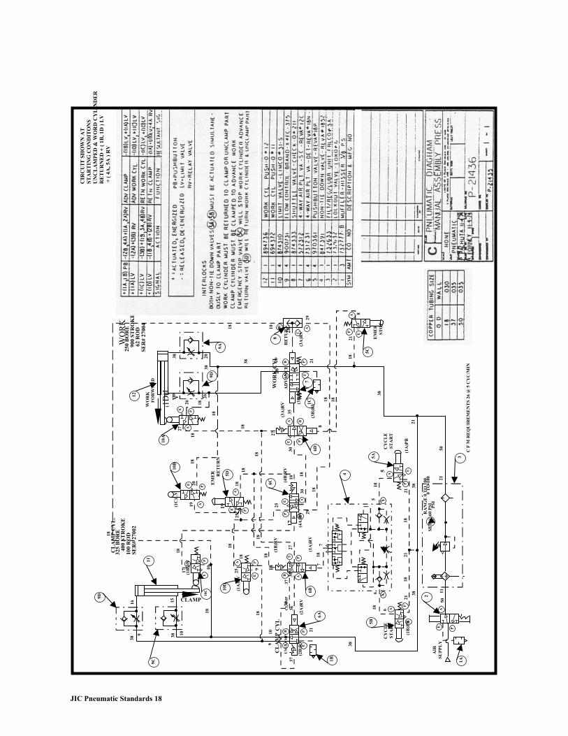
JIC Pneumatic Standards 18
WO
RK
12
FO
RW
AR
D
SE
R#
2700
462
RO
D90
0 S
TR
OK
E25
0 B
OR
EW
OR
K
CY
L.
38
38
38
20
2026
26
9A
9D
39
(1D
)LV
PE
26
18
A
18
27 18
27
18
WO
RK
CY
L
AD
VA
NC
E
EPB
AR
ET
UR
N
(3A
)RV
(3B
)RV
(3A
)RV
EA B
P
35
217
1C(3
B)R
V6D
8
28
18 10 B A
C
29
10A
10B
A
E PA
18
18
2019(1
C)L
V
EM
ER 5DRE
TU
RN
18
PE19
25
25
(4B
)RV
6C
PE A
B
18
18
1830
30
1829
17 (4A
)RV
18
18
18
1817 (1B
)LV AA
AEP
10C 10
D
1018
10
1516
38
38
18
38
9S
ER
# 27
002
100
RO
D40
0 S
TR
OK
E32
5 B
OR
EC
LA
MP
CY
L.
18
9D
9C
CLAMP
(1A
)LV E
P
25
9 18(1
B)R
V
E P
27
18
(1A
)RV
77
18
3636
AB
37
(2A
)RV
6B
6A
1B
EPB
37U
NC
LA
MP
(2B
)RV
CL
AM
P
910
CL
AM
PC
YL
21
18 18
18
8
8
38
5C
PA
E
EM
ER
ST
OP
21
518
5
4
(1B
)PB5B
P
618
38
E
AC
YC
LE
ST
AR
T
AIR
SU
PP
LY
5A
A
Y
PE
21
21
38
1821
1821
6 38X
(1A
)PB
CY
CL
ES
TA
RT
5021
1A
AE P
2
1150
3
RA
NG
E 0
TO
100
C F
M R
EQ
UIR
EM
EN
TS
26
@ 5
CY
C/M
IN
SE
T @
60
PS
I0
TO
100
PS
I
11
CIR
CU
IT S
HO
WN
AT
ST
AR
TIN
G C
ON
DIT
ON
SU
NC
LA
MP
ED
& W
OR
D C
YL
IND
ER
R
ET
UR
NE
D +
( 1
B, 1
D )
LV
+ (
4A
, 5A
) R
V

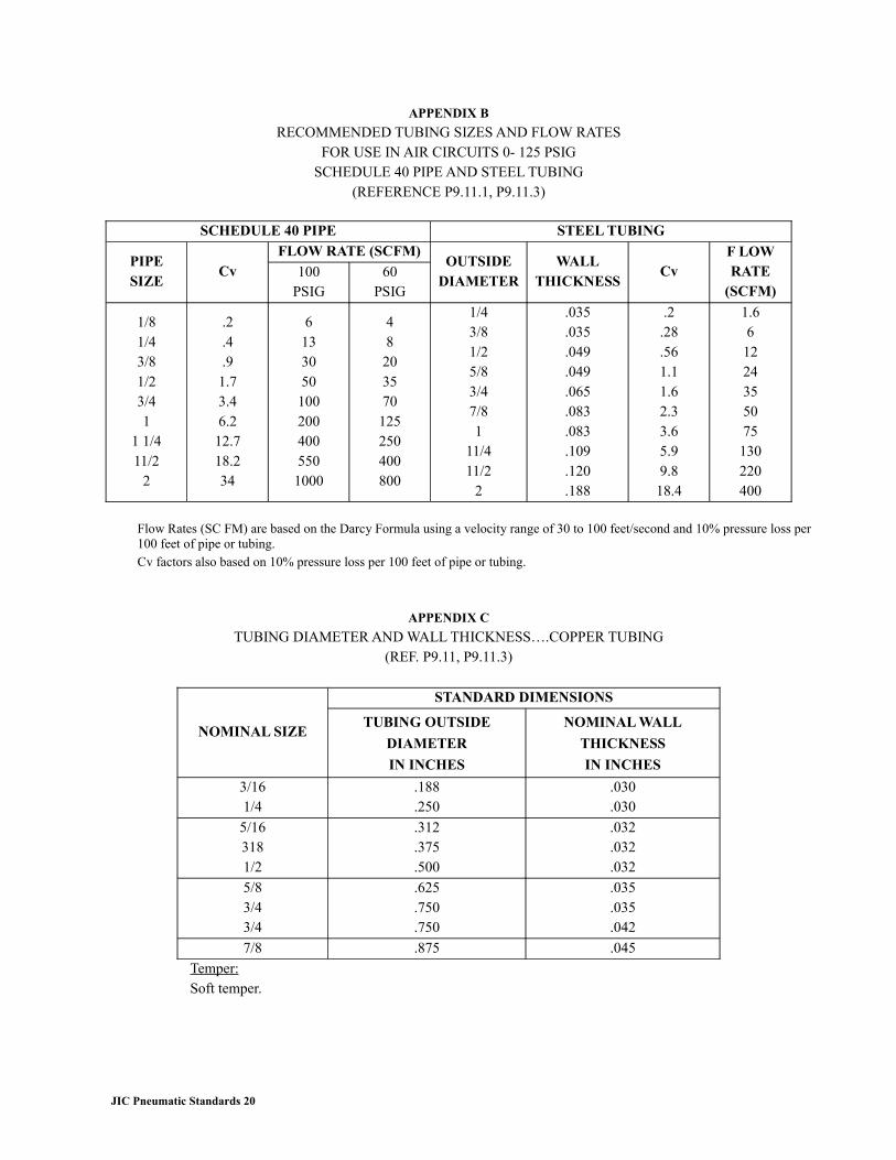
APPENDIX B
RECOMMENDED TUBING SIZES AND FLOW RATESFOR USE IN AIR CIRCUITS 0- 125 PSIG
SCHEDULE 40 PIPE AND STEEL TUBING(REFERENCE P9.11.1, P9.11.3)
SCHEDULE 40 PIPE STEEL TUBING
PIPESIZE
CvFLOW RATE (SCFM)
100PSIG
60PSIG
OUTSIDEDIAMETER
WALLTHICKNESS
CvF LOWRATE
(SCFM)
1/81/43/81/23/41
1 1/411/2
2
.2
.4
.91.73.46.212.718.234
61330501002004005501000
48203570125250400800
1/43/81/25/83/47/81
11/411/2
2
.035
.035
.049
.049
.065
.083
.083
.109
.120
.188
.2.28.561.11.62.33.65.99.818.4
1.661224355075130220400
Flow Rates (SC FM) are based on the Darcy Formula using a velocity range of 30 to 100 feet/second and 10% pressure loss per 100 feet of pipe or tubing.Cv factors also based on 10% pressure loss per 100 feet of pipe or tubing.
APPENDIX C
TUBING DIAMETER AND WALL THICKNESS….COPPER TUBING(REF. P9.11, P9.11.3)
NOMINAL SIZE
STANDARD DIMENSIONS
TUBING OUTSIDE
DIAMETER
IN INCHES
NOMINAL WALL
THICKNESS
IN INCHES
3/161/4
.188
.250.030.030
5/163181/2
.312
.375
.500
.032
.032
.032
5/83/43/4
.625
.750
.750
.035
.035
.042
7/8 .875 .045
Temper:Soft temper.
JIC Pneumatic Standards 20
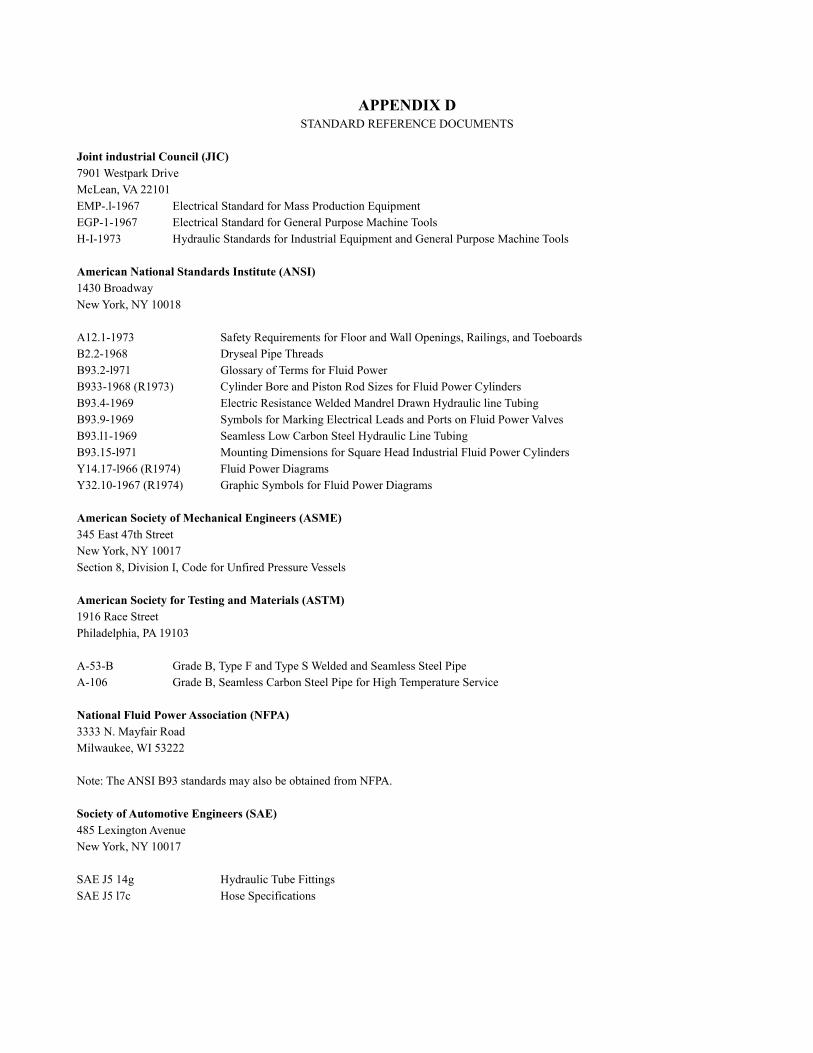
APPENDIX DSTANDARD REFERENCE DOCUMENTS
Joint industrial Council (JIC)7901 Westpark DriveMcLean, VA 22101EMP-.l-1967 Electrical Standard for Mass Production EquipmentEGP-1-1967 Electrical Standard for General Purpose Machine ToolsH-I-1973 Hydraulic Standards for Industrial Equipment and General Purpose Machine Tools
American National Standards Institute (ANSI)1430 BroadwayNew York, NY 10018
A12.1-1973 Safety Requirements for Floor and Wall Openings, Railings, and ToeboardsB2.2-1968 Dryseal Pipe ThreadsB93.2-l971 Glossary of Terms for Fluid PowerB933-1968 (R1973) Cylinder Bore and Piston Rod Sizes for Fluid Power CylindersB93.4-1969 Electric Resistance Welded Mandrel Drawn Hydraulic line TubingB93.9-1969 Symbols for Marking Electrical Leads and Ports on Fluid Power ValvesB93.l1-1969 Seamless Low Carbon Steel Hydraulic Line TubingB93.15-l971 Mounting Dimensions for Square Head Industrial Fluid Power CylindersY14.17-l966 (R1974) Fluid Power DiagramsY32.10-1967 (R1974) Graphic Symbols for Fluid Power Diagrams
American Society of Mechanical Engineers (ASME)345 East 47th StreetNew York, NY 10017Section 8, Division I, Code for Unfired Pressure Vessels
American Society for Testing and Materials (ASTM)1916 Race StreetPhiladelphia, PA 19103
A-53-B Grade B, Type F and Type S Welded and Seamless Steel PipeA-106 Grade B, Seamless Carbon Steel Pipe for High Temperature Service
National Fluid Power Association (NFPA)3333 N. Mayfair RoadMilwaukee, WI 53222
Note: The ANSI B93 standards may also be obtained from NFPA.
Society of Automotive Engineers (SAE)485 Lexington AvenueNew York, NY 10017
SAE J5 14g Hydraulic Tube FittingsSAE J5 l7c Hose Specifications
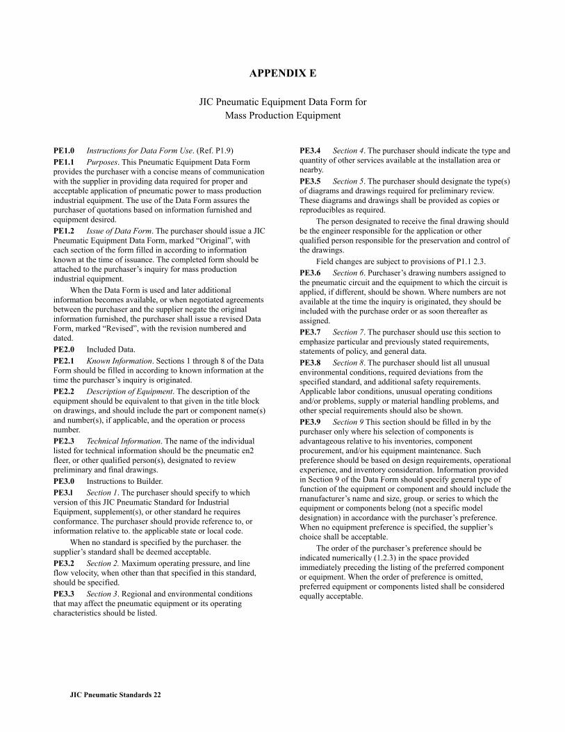
APPENDIX E
JIC Pneumatic Equipment Data Form forMass Production Equipment
PE1.0 Instructions for Data Form Use. (Ref. P1.9)PE1.1 Purposes. This Pneumatic Equipment Data Form provides the purchaser with a concise means of communication with the supplier in providing data required for proper and acceptable application of pneumatic power to mass production industrial equipment. The use of the Data Form assures the purchaser of quotations based on information furnished and equipment desired.PE1.2 Issue of Data Form. The purchaser should issue a JIC Pneumatic Equipment Data Form, marked “Original”, with each section of the form filled in according to information known at the time of issuance. The completed form should be attached to the purchaser’s inquiry for mass production industrial equipment.
When the Data Form is used and later additional information becomes available, or when negotiated agreements between the purchaser and the supplier negate the original information furnished, the purchaser shall issue a revised Data Form, marked “Revised”, with the revision numbered and dated.PE2.0 Included Data.PE2.1 Known Information. Sections 1 through 8 of the Data Form should be filled in according to known information at the time the purchaser’s inquiry is originated.PE2.2 Description of Equipment. The description of the equipment should be equivalent to that given in the title block on drawings, and should include the part or component name(s) and number(s), if applicable, and the operation or process number.PE2.3 Technical Information. The name of the individual listed for technical information should be the pneumatic en2 fleer, or other qualified person(s), designated to review preliminary and final drawings.PE3.0 Instructions to Builder.PE3.l Section 1. The purchaser should specify to which version of this JIC Pneumatic Standard for Industrial Equipment, supplement(s), or other standard he requires conformance. The purchaser should provide reference to, or information relative to. the applicable state or local code.
When no standard is specified by the purchaser. the supplier’s standard shall be deemed acceptable.PE3.2 Section 2. Maximum operating pressure, and line flow velocity, when other than that specified in this standard, should be specified.PE3.3 Section 3. Regional and environmental conditions that may affect the pneumatic equipment or its operating characteristics should be listed.
PE3.4 Section 4. The purchaser should indicate the type and quantity of other services available at the installation area or nearby.PE3.5 Section 5. The purchaser should designate the type(s) of diagrams and drawings required for preliminary review. These diagrams and drawings shall be provided as copies or reproducibles as required.
The person designated to receive the final drawing should be the engineer responsible for the application or other qualified person responsible for the preservation and control of the drawings.
Field changes are subject to provisions of P1.1 2.3.PE3.6 Section 6. Purchaser’s drawing numbers assigned to the pneumatic circuit and the equipment to which the circuit is applied, if different, should be shown. Where numbers are not available at the time the inquiry is originated, they should be included with the purchase order or as soon thereafter as assigned.PE3.7 Section 7. The purchaser should use this section to emphasize particular and previously stated requirements, statements of policy, and general data.PE3.8 Section 8. The purchaser should list all unusual environmental conditions, required deviations from the specified standard, and additional safety requirements. Applicable labor conditions, unusual operating conditions and/or problems, supply or material handling problems, and other special requirements should also be shown.PE3.9 Section 9 This section should be filled in by the purchaser only where his selection of components is advantageous relative to his inventories, component procurement, and/or his equipment maintenance. Such preference should be based on design requirements, operational experience, and inventory consideration. Information provided in Section 9 of the Data Form should specify general type of function of the equipment or component and should include the rnanufacturer’s name and size, group. or series to which the equipment or components belong (not a specific model designation) in accordance with the purchaser’s preference. When no equipment preference is specified, the supplier’s choice shall be acceptable.
The order of the purchaser’s preference should be indicated numerically (1.2.3) in the space provided immediately preceding the listing of the preferred component or equipment. When the order of preference is omitted, preferred equipment or components listed shall be considered equally acceptable.
JIC Pneumatic Standards 22
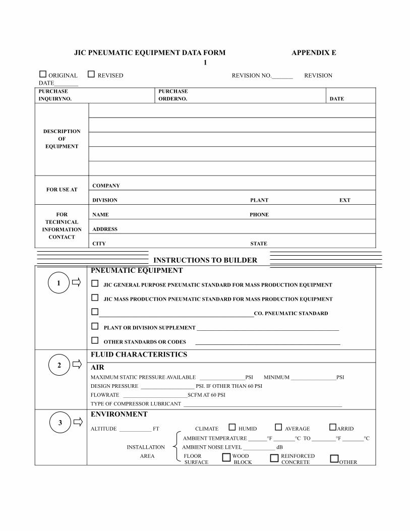
JIC PNEUMATIC EQUIPMENT DATA FORM APPENDIX E1
ORIGINAL REVISED REVISION NO._______ REVISION DATE________PURCHASE
INQUIRYNO.
PURCHASE
ORDERNO. DATE
DESCRIPTION
OF
EQUIPMENT
FOR USE ATCOMPANY
DIVISION PLANT EXT
FOR
TECHN1CAL
INFORMATION
CONTACT
NAME PHONE
ADDRESS
CITY STATE
INSTRUCTIONS TO BUILDERPNEUMATIC EQUIPMENT
JIC GENERAL PURPOSE PNEUMATIC STANDARD FOR MASS PRODUCTION EQUIPMENT
JIC MASS PRODUCTION PNEUMATIC STANDARD FOR MASS PRODUCTION EQUIPMENT
_________________________________CO. PNEUMATIC STANDARD
PLANT OR DIVISION SUPPLEMENT _____________________________________________________
OTHER STANDARDS OR CODES ______________________________________________________
FLUID CHARACTERISTICS
AIRMAXIMUM STATIC PRESSURE AVAILABLE _________________PSI MINIMUM _________________PSI
DESIGN PRESSURE ____________________ PSI. IF OTHER THAN 60 PSI
FLOWRATE ________________________SCFM AT 60 PSI
TYPE OF COMPRESSOR LUBRICANT ___________________________________________________________
ENVIRONMENT
ALTITUDE ____________ FT CLIMATE HUMID AVERAGE ARRID
AMBIENT TEMPERATURE _______°F ________°C TO _________°F ________°C
INSTALLATION AMBIENT NOISE LEVEL ____________ dB
AREA FLOOR WOOD REINFORCED SURFACE BLOCK CONCRETE OTHER
1
2
3
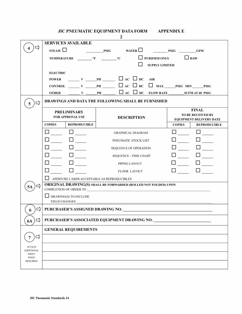
JIC PNEUMATIC EQUIPMENT DATA FORM APPENDIX E2
SERVICES AVAILABLE
STEAM ___________PSIG WATER _________ PSIG ___________GPM
TEMPERATURE _________ °F __________°C PURIFIED ONLY HAW
SUPPLY LIMITED
ELECTRIC
POWER _______ V _______PH ________ AC DC AIR
CONTROL _______ V _______PH ________ AC DC MAX _______PSIG MIN _______PSIG
OTHER _______ V _______PH ________ AC DC FLOW RATE __________SCFM AT 60 PSIG
DRAWINGS AND DATA THE FOLLOWING SHALL BE FURNISHED
PRELIMINARYFOR APPROVAL USE
COPIES REPRODUCIBLE
DESCRIPTION
FINALTO BE RECEIVED BY
EQUIPMENT DELIVERY DATE
COPIES REPRODUCIBLE
____ ____ GRAPHICAL DIAGRAM ____ ____
____ ____ PNEUMATIC STOCK LIST ____ ____
____ ____ SEQUENCE OF OPERATION ____ ____
____ ____ SEQUENCE - TIME CHART ____ ____
____ ____ PIPING LAYOUT ____ ____
____ ____ FLOOR LAYOUT ____ ____
APERTURE CARDS ACCEPTABLE AS REPROQUCIBLES
ORIGINAL DRAWING(S) SHALL BE FORWARDED (ROLLED NOT FOLDED) UPON
COMPLETION OF ORDER TO ______________________________________________________________________________
DRAWING(S) TO INCLUDE
FIELD CHANGES ______________________________________________________________________________________
PURCHASER’S ASSIGNED DRAWING NO. _____________________________________________
PURCHASER’S ASSOCIATED EQUIPMENT DRAWING NO. _____________________________
ATTACH
ADDITIONAL
SHEET
WHEN
REQUIRED
GENERAL REQUIREMENTS
JIC Pneumatic Standards 24
4
5
5A
6
6A
7
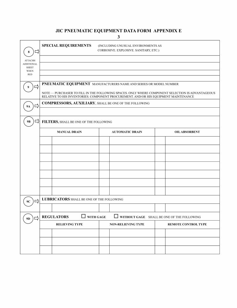
JIC PNEUMATIC EQUIPMENT DATA FORM APPENDIX E3
ATTACHH
ADDITIONAL
SHEET
WHEN
RED
SPECIAL REQUIREMENTS (INCLUDING UNUSUAL ENVIRONMENTS AS
CORROSIVE. EXPLOSIVE. SANITARY, ETC.)
PNEUMATIC EQUIPMENT MANUFACTURERS NAME AND SERIES OR MODEL NUMBER
NOTE — PURCHASER TO FILL IN THE FOLLOWING SPACES. ONLY WHERE COMPONENT SELECTION IS ADVANTAGEOUS RELATIVE TO HIS INVENTORIES. COMPONENT PROCUREMENT. AND/OR HIS EQUIPMENT MAINTENANCE
COMPRESSORS, AUXILIARY, SHALL BE ONE OF THE FOLLOWING
FILTERS, SHALL BE ONE OF THE FOLLOWING
MANUAL DRAIN AUTOMATIC DRAIN OIL ABSORBENT
LUBRICATORS SHALL BE ONE OF THE FOLLOWING
REGULATORS WITH GAGE WITHOUT GAGE SHALL BE ONE OF THE FOLLOWING
RELIEVING TYPE NON-RELIEVING TYPE REMOTE CONTROL TYPE
8
9
9A
9B
9C
9D
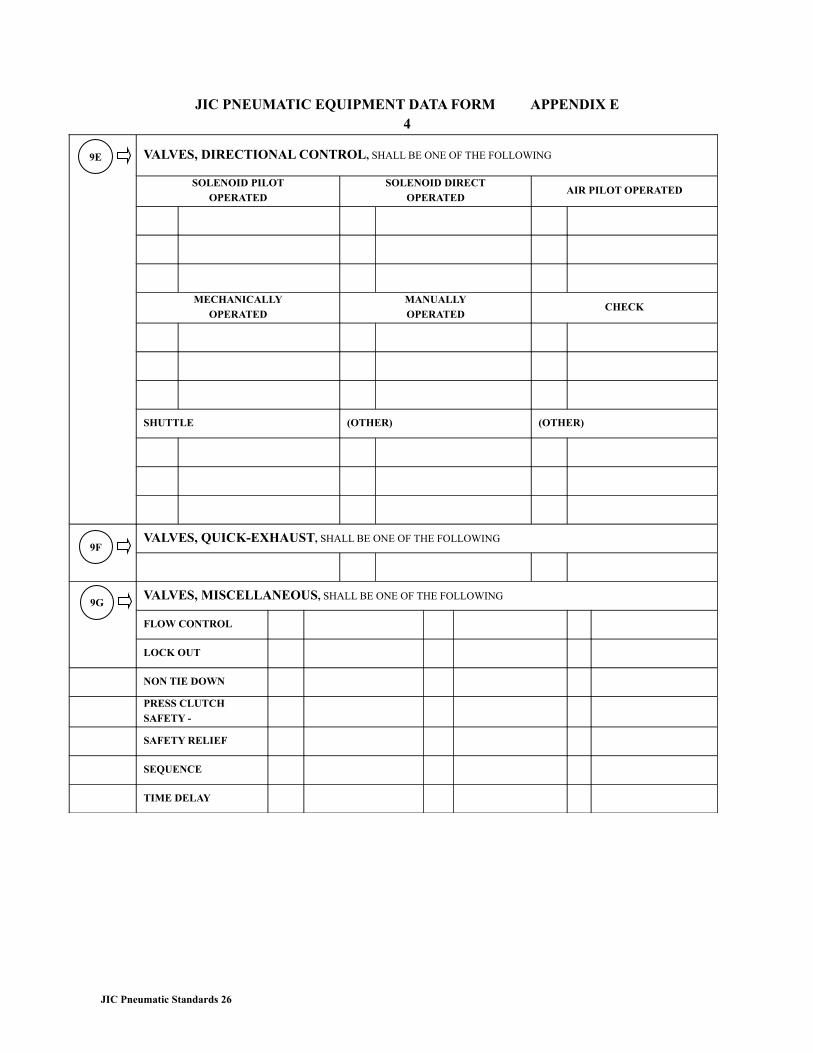
JIC PNEUMATIC EQUIPMENT DATA FORM APPENDIX E4
VALVES, DIRECTIONAL CONTROL, SHALL BE ONE OF THE FOLLOWING
SOLENOID PILOT
OPERATED
SOLENOID DIRECT
OPERATEDAIR PILOT OPERATED
MECHANICALLY
OPERATED
MANUALLY
OPERATEDCHECK
SHUTTLE (OTHER) (OTHER)
VALVES, QUICK-EXHAUST, SHALL BE ONE OF THE FOLLOWING
VALVES, MISCELLANEOUS, SHALL BE ONE OF THE FOLLOWING
FLOW CONTROL
LOCK OUT
NON TIE DOWN
PRESS CLUTCH
SAFETY -
SAFETY RELIEF
SEQUENCE
TIME DELAY
JIC Pneumatic Standards 26
9G
9E
9F
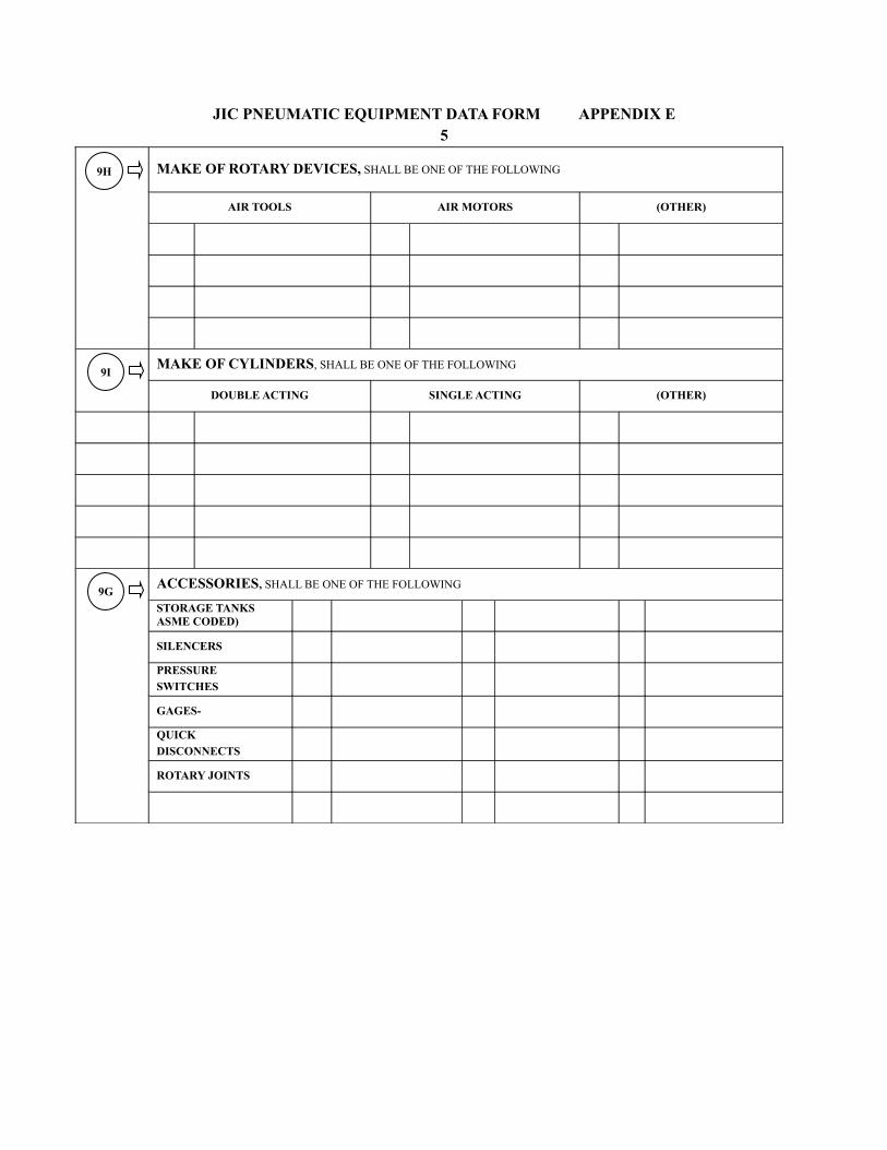
JIC PNEUMATIC EQUIPMENT DATA FORM APPENDIX E5
MAKE OF ROTARY DEVICES, SHALL BE ONE OF THE FOLLOWING
AIR TOOLS AIR MOTORS (OTHER)
MAKE OF CYLINDERS, SHALL BE ONE OF THE FOLLOWING
DOUBLE ACTING SINGLE ACTING (OTHER)
ACCESSORIES, SHALL BE ONE OF THE FOLLOWING
STORAGE TANKS ASME CODED)
SILENCERS
PRESSURE
SWITCHES
GAGES-
QUICK
DISCONNECTS
ROTARY JOINTS
9H
9I
9G
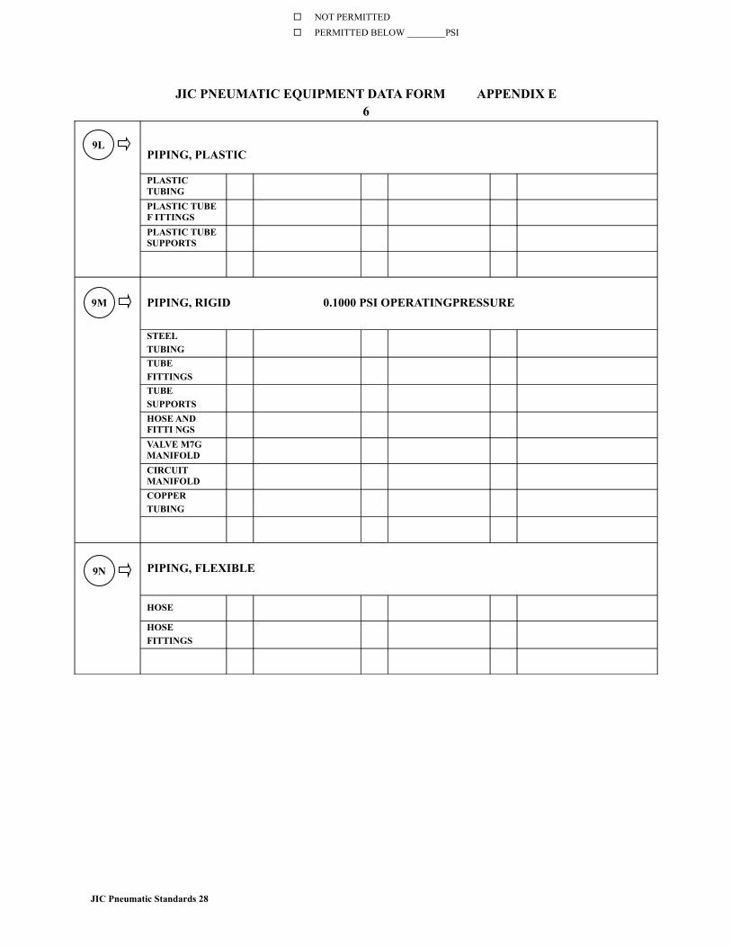
JIC PNEUMATIC EQUIPMENT DATA FORM APPENDIX E6
PIPING, PLASTIC
PLASTIC TUBING
PLASTIC TUBE F ITTINGS
PLASTIC TUBE SUPPORTS
PIPING, RIGID 0.1000 PSI OPERATINGPRESSURE
STEEL
TUBING
TUBE
FITTINGS
TUBE
SUPPORTS
HOSE AND FITTI NGS
VALVE M7G MANIFOLD
CIRCUIT MANIFOLD
COPPER
TUBING
PIPING, FLEXIBLE
HOSE
HOSE
FITTINGS
JIC Pneumatic Standards 28
9L
NOT PERMITTED
PERMITTED BELOW ________PSI
9M
9N
JIC PNEUMATIC EQUIPMENT DATA FORM APPENDIX E7
NOTE PURCHASER TO FILL OUT FOLLOWING BLANKS FOR MAJOR COMPONENTS USED LESS FREQUENTLY IN PNEUMATIC CIRCUJTS. SUCH AS FLOW DIVIDERS. ETC
9O