Embed Size (px)
Citation preview

1
14th
Searnet International RWH Conference – Mpumalanga, South Africa
Title Ferro-cement rainwater harvesting tanks store rainwater and can simultaneously act
as wells where there is a high water table, facilitating vegetable production and
mitigating climate change.
Author:
Dr Nicholas Papenfus - Private Bag X09, Suite 499, Weltevreden Park, 1709, Johannesburg, South
Africa. [email protected]
Mr Chris Stimie – P O Box32577, Totiusdal, 0134, Pretoria, South Africa. [email protected]
Abstract
Generally RWH tanks that are situated above ground are positioned below a gutter to capture roof
runoff – and providing a first flush system is installed, the water should be safe to drink. Underground
tanks on the other hand may be more strategically positioned to additionally capture ground runoff,
from virtually the whole property, and perhaps even from the street or some other watercourse/gully.
While this water is not fit for human consumption, substantially more water can be captured - for
irrigation of vegetable gardens – and of course such vegetation converts CO2 into organic matter,
mitigating climate change.
Furthermore it is possible to build these tanks from ferro-cement (FC), which are thin shelled
structures, and as such use substantially less cement than conventional tanks made with concrete
floors and concrete block walls. The FC structures also mitigate climate change, since for every kg of
cement saved there is a corresponding saving in CO2. (In the production of cement approximately one
kg of CO2 is emitted into the atmosphere for each kg of cement produced).
It is also possible, even advantageous, to build such tanks in ground which has a high water table, and
in this case the tank can simultaneously act as a well, providing certain features are added.
For example, to prevent the thin FC floor slab from bulging upwards owing to external water pressure
(in the case of an empty tank and a high water table), a simple and cost effective non return valve can
be installed in the floor. This allows water into the tank from below the floor up to the height of the
prevailing water table, and this relieves the bulging pressure. This additional water can be quite
substantial in the case where there is an underground aquifer, and can be used for a corresponding
increase in crop production.
The non-return valve is designed to close the moment the level inside the tank exceeds the level of the
water table outside, thus any incoming rain water into the tank will not escape via the valve. (In this
case there will be a net downward pressure applied to the floor-slab, but there is no danger of it
bulging downwards since it is supported by the ground).
The non-return valve also safeguards against flotation of the relatively light tank out of the ground,
since flotation cannot occur so long as the water levels inside and outside the tank are equal.
The non-return valve and other features are illustrated by way of photographs and diagrams of a tank
constructed in Mpumalanga province.
2
Ferro-cement rainwater harvesting tanks store rainwater and can simultaneously act as wells
where there is a high water table, facilitating vegetable production and mitigating climate
change.
Background
Pastor Hendrik Mahlangu and Professor James Blignaut envisaged building a rain water harvesting
cistern for the Alethea Bible College in a village, Siyabuswa, Mpumalanga, South Africa, with the
idea of providing water to grow crops and for adding with the feedstock for a proposed biodigester (1).
However, in April 2010, when construction was to commence, the excavation had partially filled with
water. It was evident that the 2.3m deep excavation had intersected the path of an aquifer which had
filled the excavation to a depth of approximately 700mm.
Figure 1 – A view of the innundated excavation
It became evident that this ‘problem’ could be turned into a ‘blessing’ by installing a ‘non return
valve’ (NRV) in the floor of the proposed cistern. Such a vlave would allow ground water in when
the water table was high, but not allow water out when the water table was low! In other words the
cistern would then have the ability to function as a well and as a reservoir, depending on the relative
level of the water inside and outside the structure.
3
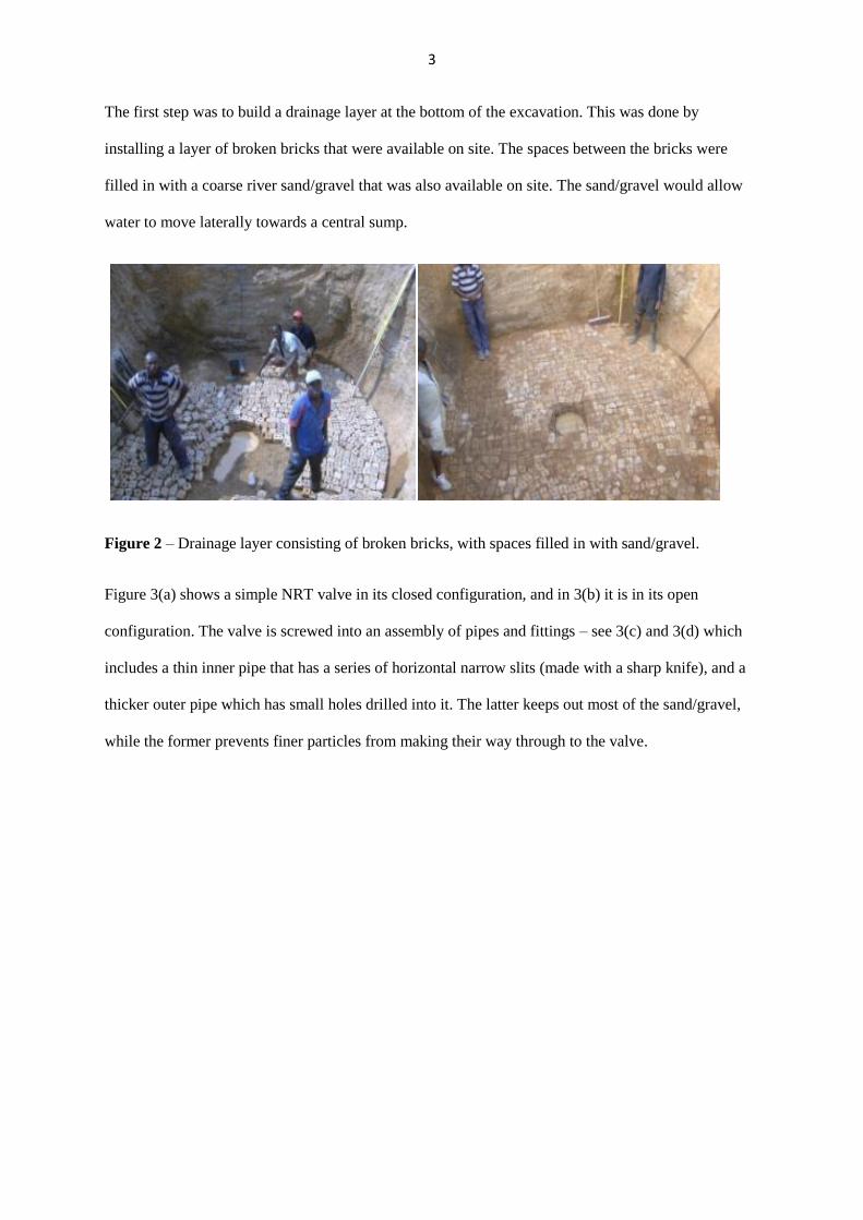
The first step was to build a drainage layer at the bottom of the excavation. This was done by
installing a layer of broken bricks that were available on site. The spaces between the bricks were
filled in with a coarse river sand/gravel that was also available on site. The sand/gravel would allow
water to move laterally towards a central sump.
Figure 2 – Drainage layer consisting of broken bricks, with spaces filled in with sand/gravel.
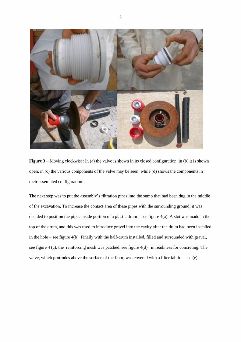
Figure 3(a) shows a simple NRT valve in its closed configuration, and in 3(b) it is in its open
configuration. The valve is screwed into an assembly of pipes and fittings – see 3(c) and 3(d) which
includes a thin inner pipe that has a series of horizontal narrow slits (made with a sharp knife), and a
thicker outer pipe which has small holes drilled into it. The latter keeps out most of the sand/gravel,
while the former prevents finer particles from making their way through to the valve.
4
Figure 3 – Moving clockwise: In (a) the valve is shown in its closed configuration, in (b) it is shown
open, in (c) the various components of the valve may be seen, while (d) shows the components in
their assembled configuration.
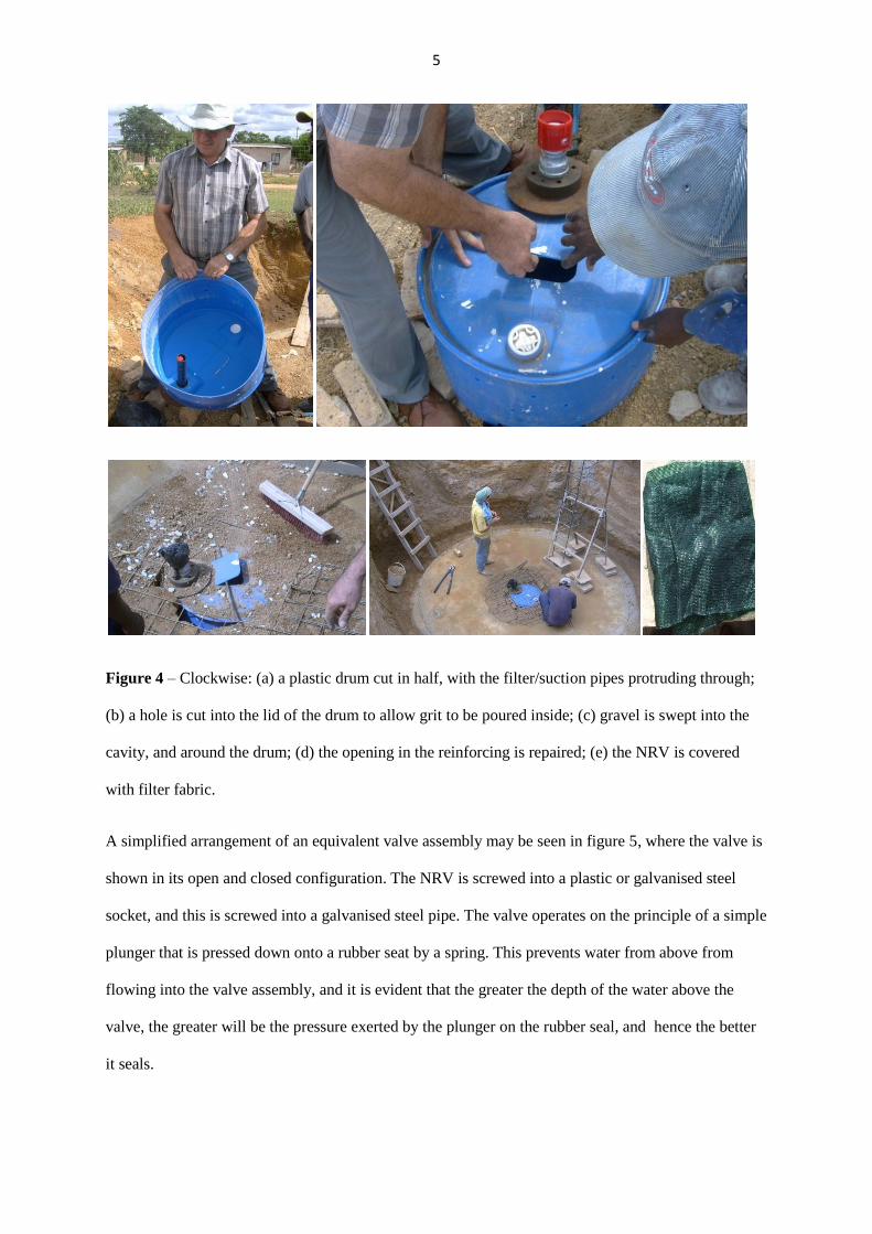
The next step was to put the assembly’s filtration pipes into the sump that had been dug in the middle
of the excavation. To increase the contact area of these pipes with the surrounding ground, it was
decided to position the pipes inside portion of a plastic drum – see figure 4(a). A slot was made in the
top of the drum, and this was used to introduce gravel into the cavity after the drum had been installed
in the hole – see figure 4(b). Finally with the half-drum installed, filled and surrounded with gravel,
see figure 4 (c), the reinforcing mesh was patched, see figure 4(d), in readiness for concreting. The
valve, which protrudes above the surface of the floor, was covered with a filter fabric – see (e).
5
Figure 4 – Clockwise: (a) a plastic drum cut in half, with the filter/suction pipes protruding through;
(b) a hole is cut into the lid of the drum to allow grit to be poured inside; (c) gravel is swept into the
cavity, and around the drum; (d) the opening in the reinforcing is repaired; (e) the NRV is covered
with filter fabric.
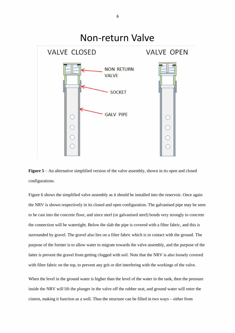
A simplified arrangement of an equivalent valve assembly may be seen in figure 5, where the valve is
shown in its open and closed configuration. The NRV is screwed into a plastic or galvanised steel
socket, and this is screwed into a galvanised steel pipe. The valve operates on the principle of a simple
plunger that is pressed down onto a rubber seat by a spring. This prevents water from above from
flowing into the valve assembly, and it is evident that the greater the depth of the water above the
valve, the greater will be the pressure exerted by the plunger on the rubber seal, and hence the better
it seals.
6
Non-return Valve
Figure 5 – An alternative simplified version of the valve assembly, shown in its open and closed
configurations.
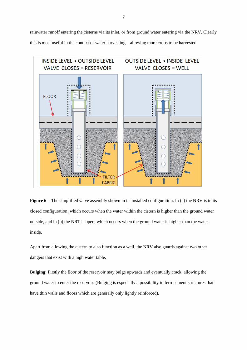
Figure 6 shows the simplified valve assembly as it should be installed into the reservoir. Once again
the NRV is shown respectively in its closed and open configuration. The galvanised pipe may be seen
to be cast into the concrete floor, and since steel (or galvanised steel) bonds very strongly to concrete
the connection will be watertight. Below the slab the pipe is covered with a filter fabric, and this is
surrounded by gravel. The gravel also lies on a filter fabric which is in contact with the ground. The
purpose of the former is to allow water to migrate towards the valve assembly, and the purpose of the
latter is prevent the gravel from getting clogged with soil. Note that the NRV is also loosely covered
with filter fabric on the top, to prevent any grit or dirt interfering with the workings of the valve.
When the level in the ground water is higher than the level of the water in the tank, then the pressure
inside the NRV will lift the plunger in the valve off the rubber seat, and ground water will enter the
cistern, making it function as a well. Thus the structure can be filled in two ways – either from
7
rainwater runoff entering the cisterns via its inlet, or from ground water entering via the NRV. Clearly
this is most useful in the context of water harvesting – allowing more crops to be harvested.
Figure 6 - The simplified valve assembly shown in its installed configuration. In (a) the NRV is in its
closed configuration, which occurs when the water within the cistern is higher than the ground water
outside, and in (b) the NRT is open, which occurs when the ground water is higher than the water
inside.
Apart from allowing the cistern to also function as a well, the NRV also guards against two other
dangers that exist with a high water table.
Bulging: Firstly the floor of the reservoir may bulge upwards and eventually crack, allowing the
ground water to enter the reservoir. (Bulging is especially a possibility in ferrocement structures that
have thin walls and floors which are generally only lightly reinforced).
8
Later, when rain water fills the reservoir the slab will move down again, and the water inside the
cistern will leak out through the cracks. The more this cycle is repeated the more the cracks will open
up, and eventually the slab may begin to disintegrate.
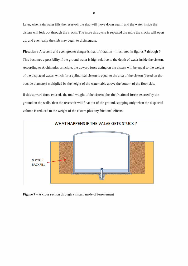
Flotation : A second and even greater danger is that of flotation – illustrated in figures 7 through 9.
This becomes a possibility if the ground water is high relative to the depth of water inside the cistern.
According to Archimedes principle, the upward force acting on the cistern will be equal to the weight
of the displaced water, which for a cylindrical cistern is equal to the area of the cistern (based on the
outside diameter) multiplied by the height of the water table above the bottom of the floor slab.
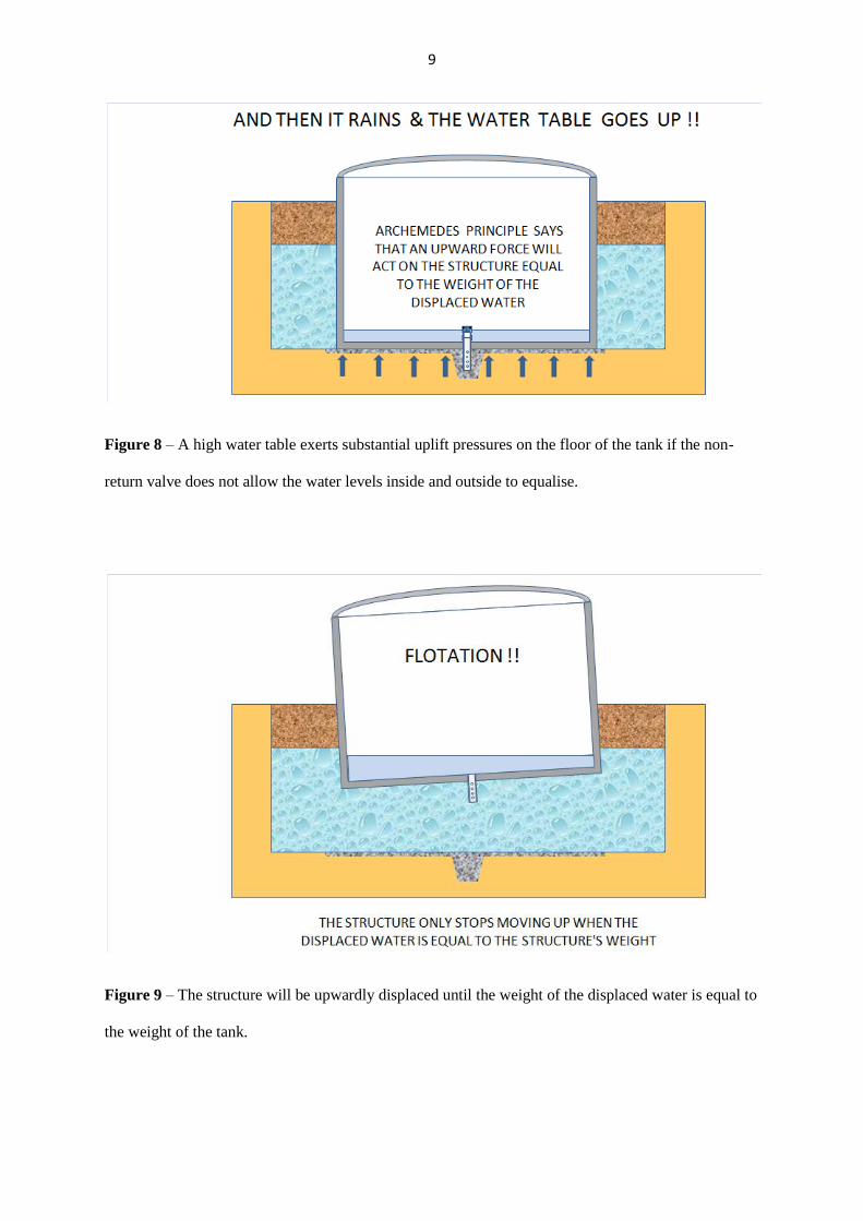
If this upward force exceeds the total weight of the cistern plus the frictional forces exerted by the
ground on the walls, then the reservoir will float out of the ground, stopping only when the displaced
volume is reduced to the weight of the cistern plus any frictional effects.
Figure 7 – A cross section through a cistern made of ferrocement
9
Figure 8 – A high water table exerts substantial uplift pressures on the floor of the tank if the non-
return valve does not allow the water levels inside and outside to equalise.
Figure 9 – The structure will be upwardly displaced until the weight of the displaced water is equal to
the weight of the tank.
10
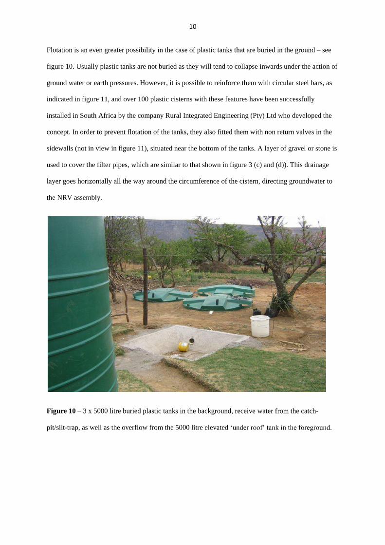
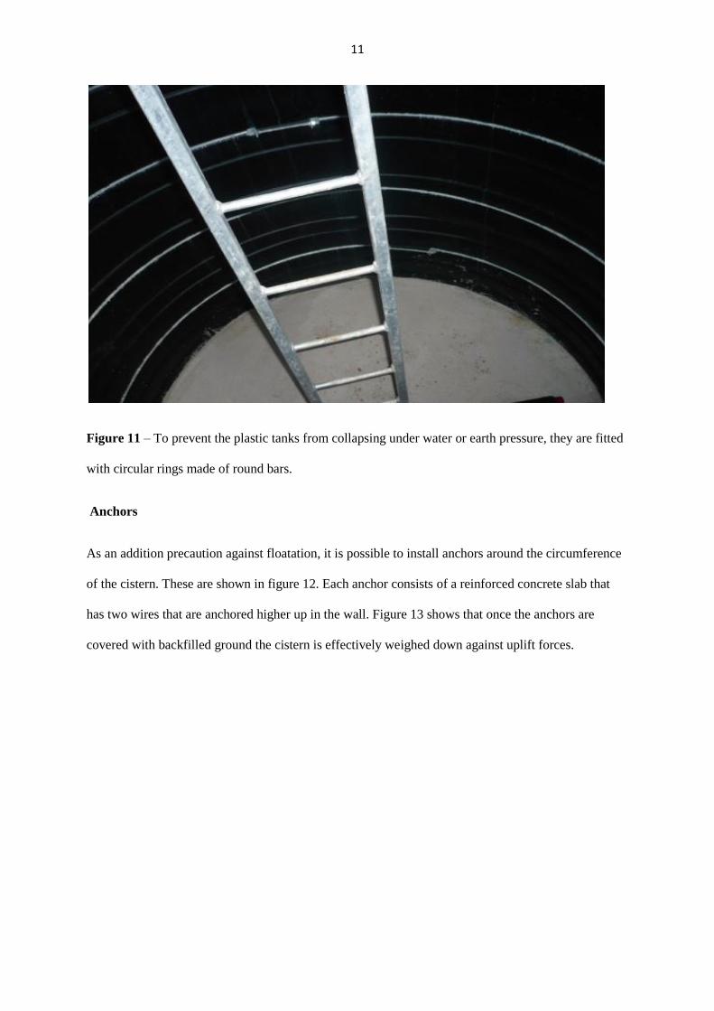
Flotation is an even greater possibility in the case of plastic tanks that are buried in the ground – see
figure 10. Usually plastic tanks are not buried as they will tend to collapse inwards under the action of
ground water or earth pressures. However, it is possible to reinforce them with circular steel bars, as
indicated in figure 11, and over 100 plastic cisterns with these features have been successfully
installed in South Africa by the company Rural Integrated Engineering (Pty) Ltd who developed the
concept. In order to prevent flotation of the tanks, they also fitted them with non return valves in the
sidewalls (not in view in figure 11), situated near the bottom of the tanks. A layer of gravel or stone is
used to cover the filter pipes, which are similar to that shown in figure 3 (c) and (d)). This drainage
layer goes horizontally all the way around the circumference of the cistern, directing groundwater to
the NRV assembly.
Figure 10 – 3 x 5000 litre buried plastic tanks in the background, receive water from the catch-
pit/silt-trap, as well as the overflow from the 5000 litre elevated ‘under roof’ tank in the foreground.
11
Figure 11 – To prevent the plastic tanks from collapsing under water or earth pressure, they are fitted
with circular rings made of round bars.
Anchors
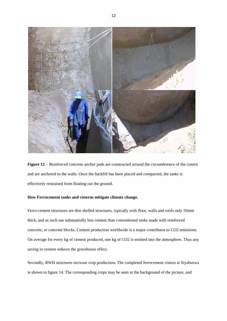
As an addition precaution against floatation, it is possible to install anchors around the circumference
of the cistern. These are shown in figure 12. Each anchor consists of a reinforced concrete slab that
has two wires that are anchored higher up in the wall. Figure 13 shows that once the anchors are
covered with backfilled ground the cistern is effectively weighed down against uplift forces.
12
Figure 12 - Reinforced concrete anchor pads are constructed around the circumference of the cistern
and are anchored to the walls. Once the backfill has been placed and compacted, the tanks is
effectively restrained from floating out the ground.
How Ferrocement tanks and cisterns mitigate climate change.
Ferro-cement structures are thin shelled structures, typically with floor, walls and roofs only 50mm
thick, and as such use substantially less cement than conventional tanks made with reinforced
concrete, or concrete blocks. Cement production worldwide is a major contributor to CO2 emissions.
On average for every kg of cement produced, one kg of CO2 is emitted into the atmosphere. Thus any
saving in cement reduces the greenhouse effect.
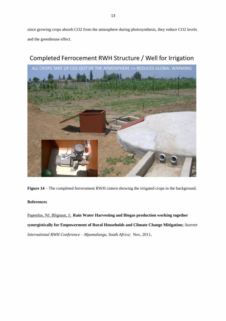
Secondly, RWH structures increase crop production. The completed ferrocement cistern at Siyabuswa
is shown in figure 14. The corresponding crops may be seen in the background of the picture, and
13
since growing crops absorb CO2 from the atmosphere during photosynthesis, they reduce CO2 levels
and the greenhouse effect.
Completed Ferrocement RWH Structure / Well for Irrigation
ALL CROPS TAKE UP CO2 OUT OF THE ATMOSPHERE >> REDUCES GLOBAL WARMING
Figure 14 – The completed ferrocement RWH cistern showing the irrigated crops in the background.
References
Papenfus, NJ, Blignaut, J; Rain Water Harvesting and Biogas production working together
synergistically for Empowerment of Rural Households and Climate Change Mitigation; Searnet
International RWH Conference – Mpumalanga, South Africa; Nov, 2011.

![Evaluation of Rainwater Harvesting Methods and Structures Using Analytical … · 2013-12-24 · vesting techniques (RWH) [1]. The term RWH implies conservation of rainwater where](https://img.pdfslide.us/doc/110x75/5edc5023ad6a402d6666ed9a/evaluation-of-rainwater-harvesting-methods-and-structures-using-analytical-2013-12-24.jpg)