Embed Size (px)
Citation preview

7/25/2019 13615314 Vopak Fuel 3 Waste Water Study
http://slidepdf.com/reader/full/13615314-vopak-fuel-3-waste-water-study 1/34

7/25/2019 13615314 Vopak Fuel 3 Waste Water Study
http://slidepdf.com/reader/full/13615314-vopak-fuel-3-waste-water-study 2/34
VOPAK FUEL 3: WATER AND WASTE SPECIALIST STUDY
January 2014Report No. 13615314 - 12583 - 5 i
Table of Contents
1.0 INTRODUCTION AND BACKGROUND ................................................................. ................................................... 1
1.1 Study Site –Vopak Terminal Durban ........................................................... ................................................... 2
1.1.1 Project Location ...................................................................................................................................... 2
1.2 Current Operations ....................................................................................................................................... 2
1.2.1 Fynn Site .............................................................. ................................................................. .................. 2
1.2.2 Blend Site ............................................................. ................................................................. .................. 3
1.3 Information on Topography .............................................................. ............................................................. 3
1.4 Modifications .............................................................. ................................................................. .................. 4
1.4.1 Upgrade Phase Fynn Site .......................................................... ............................................................. 4
1.4.1.1 Demolition ......................................................... ................................................................. .................. 4
1.4.1.2 Construction ........................................................................................................................................ 5
1.4.2 Upgrade Phase Blend Site ......................................................... ............................................................. 6
1.4.2.1 Demolition ......................................................... ................................................................. .................. 6
1.4.2.2 Construction ........................................................................................................................................ 7
1.4.3
Tank design ............................................................................................................................................ 7
1.4.4 Interconnecting pipelines ........................................................................................................................ 8
1.4.5 Fire prevention and protection ................................................................................................................ 9
1.4.6 New infrastructure ........................................................... ................................................................. ....... 9
1.4.6.1 Storm and waste water ........................................................... ............................................................. 9
1.4.6.2 Nitrogen ............................................................ ................................................................. .................. 9
1.4.6.3 Waste Management ................................................................ ............................................................. 9
1.4.7
Utilities .................................................................................................................................................. 10
1.4.8 Design Standards and Criteria ............................................................. ................................................. 10
1.5 Operational Phase ..................................................... ................................................................. ................ 10
1.5.1 Plant .......................................................... ................................................................. ........................... 10
2.0 RELEVANT LEGISLATION ............................................................... ................................................................. ..... 11
3.0 APPROACH AND METHODS ................................................................................................................................. 12
3.1 Review of Effluent Discharge Quality Requirements .................................................................................. 12
3.1.1 National Water Act ................................................................................................................................ 12
3.1.2 Sewage Disposal By-Laws ......................................................... ........................................................... 13
3.1.2.1 Effluent Specifications ....................................................................................................................... 13

7/25/2019 13615314 Vopak Fuel 3 Waste Water Study
http://slidepdf.com/reader/full/13615314-vopak-fuel-3-waste-water-study 3/34
VOPAK FUEL 3: WATER AND WASTE SPECIALIST STUDY
January 2014Report No. 13615314 - 12583 - 5 ii
3.1.2.2 Implications for Vopak ....................................................................................................................... 15
3.1.3 National Environmental Management Integrated Coastal Management Act ......................................... 15
3.2 National Environmental Management Waste Act................................................................................ ........ 15
3.2.1 Vopak’s Soil and Groundwater Remediation .............................................................. ........................... 16
3.3 Evaluation of Water and Waste Impacts of Vopak’s Current Operations .................................................... 17
3.3.1 Water Use ............................................................................................................................................. 17
3.3.2 Wastewater Streams ................................................................. ............................................................ 17
3.3.2.1 Non contaminated rainwater ............................................................. ................................................. 17
3.3.2.2 Oily/hydrocarbon/organic waste ........................................................................................................ 17
3.3.2.3
Rainwater from tank pits ......................................................... ........................................................... 17
3.3.2.4 Tank cleaning waste ............................................................... ........................................................... 18
3.3.2.5 Spills/off spec product ............................................................. ........................................................... 18
3.3.2.6 Sanitary waste ............................................................. ................................................................. ..... 18
3.3.3 Waste ........................................................ ................................................................. ........................... 18
3.3.3.1 Tank and Line Washings ................................................................................................................... 18
3.3.3.2 Slops ...................................................... ................................................................. ........................... 18
3.3.3.3 Operational Areas ........................................................ ................................................................. ..... 18
3.3.3.4 Emergency Waste ............................................................................................................................. 19
3.3.3.5 Solid Waste ....................................................................................................................................... 20
3.3.4 Overview of Vopak’s Waste Handling Philosophy ................................................................ ................. 20
3.3.4.1 Waste Water ..................................................... ................................................................. ................ 21
3.3.4.2 New Separators Designs ........................................................ ........................................................... 21
3.3.4.3 Vapour Handling .......................................................... ................................................................. ..... 21
3.3.4.4 Solid Waste ....................................................................................................................................... 21
3.3.5
Identification of Waste Sources during Upgrading and Operations ....................................................... 22
3.3.5.1 Wastewater ....................................................... ................................................................. ................ 22
3.3.5.2 Solid Waste ....................................................................................................................................... 22
3.3.5.3 Slops ...................................................... ................................................................. ........................... 22
3.3.5.4 Waste generated from operational areas ................................................................ ........................... 23
3.3.5.5 Waste from emissions abatement technology ........................................................................... ........ 23
3.3.5.6 Sewage ............................................................. ................................................................. ................ 23
3.3.6
Emergency Wastes ......................................................... ................................................................. ..... 23
3.3.6.1
Spills .................................................................................................................................................. 23

7/25/2019 13615314 Vopak Fuel 3 Waste Water Study
http://slidepdf.com/reader/full/13615314-vopak-fuel-3-waste-water-study 4/34
VOPAK FUEL 3: WATER AND WASTE SPECIALIST STUDY
January 2014Report No. 13615314 - 12583 - 5 iii
3.3.6.2 Major Incidents .................................................................................................................................. 23
3.4 Overview of Waste Minimisation measures proposed by Vopak .......................... ...................................... 23
3.5 Identification and Evaluation of Impacts ..................................................................................................... 24
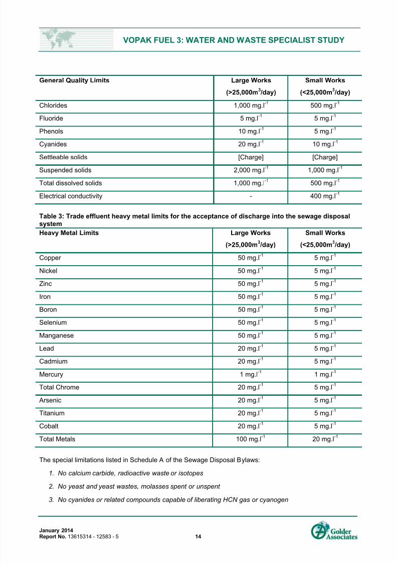
3.5.1 Impact Assessment Methodology ........................................................ ................................................. 24
4.0 RATING AND DICUSSION OF IMPACTS .............................................................. ................................................. 25
4.1.1 Increased water use during upgrading activities ........................................................................... ........ 25
4.1.2 Generation of general waste during upgrading activities....................................................................... 25
4.2 Operations Phase ...................................................... ................................................................. ................ 26
5.0 ASSUMPTIONS AND UNCERTAINTIES ................................................................................................................ 26
6.0
REFERENCES ............................................................. ................................................................. ........................... 27
TABLES
Table 1: Listed activities triggered by the proposed project......................................................... ............................................... 1
Table 2: Trade effluent general quality limits for the acceptance of discharge into the sewage disposal system..................... 13
Table 3: Trade effluent heavy metal limits for the acceptance of discharge into the sewage disposal system ........................ 14
Table 4: Procedure for the handling of non-hazardous solid waste at Vopak's Fynn and Blend Sites. .................................... 20
Table 5: Environmental Impact Assessment Matrix for the proposed Project - Upgrading Phase ............................................ 26
Table 6: Environmental Impact Assessment Matrix for the proposed Project – Operation Phase ............................................ 26
FIGURES
Figure 1: The location of the Vopak Terminal in relation to the rest of South Africa ............................................................. ...... 2
Figure 2: Aerial photo of the four Vopak sites in the Port of Durban. Note King/ Farwell sites are shown forreference and are not included in the Vopak Fuel 3 project. ................................................. .................................... 3
Figure 3: Aerial photograph of A) Fynn Site and B) Blend Site ................................................... ............................................... 4
Figure 4: Fynn Site layout showing tanks to be removed ........................................................................................................... 5
Figure 5: Layout of tanks on the modified Fynn Site ........................................................ .......................................................... 6
Figure 6: Blend Site layout showing proposed demolition. ................................................................................................... ...... 6
Figure 7: New layout of the Blend Site ................................................................................................... .................................... 7
Figure 8: Typical arrangement of a petrol and diesel storage tank ......................................................... .................................. 11
APPENDICES
APPENDIX A
Document Limitations

7/25/2019 13615314 Vopak Fuel 3 Waste Water Study
http://slidepdf.com/reader/full/13615314-vopak-fuel-3-waste-water-study 5/34
VOPAK FUEL 3: WATER AND WASTE SPECIALIST STUDY
January 2014Report No. 13615314 - 12583 - 5 1
1.0 INTRODUCTION AND BACKGROUND
The current storage facilities in Durban are not adequate to meet the growing inflows and outflows of both
petroleum and chemical products in the region. Durban harbour is strategically located to serve InlandRegions because of its proximity and capacity. Vopak Terminal Durban (Vopak) already operates a storage
terminal at the port of Durban. The four sites at the terminal are primarily designed for chemical imports,
which are imported by ship and distributed throughout the Republic of South Africa (RSA) by rail, road and in
drums. The lack of suitable land in the Durban Port for expansion of the terminal has resulted in a strategy to
optimise the existing sites to better suit future business and market requirements in RSA. Vopak propose a
60 000m3 upgrade project as a necessity to meet the growing needs of RSA.
Vopak propose upgrading the Fynn and Blend Sites by removing some existing infrastructure and
constructing new infrastructure to comply with leading industry standards. Vopak’s current infrastructure on
the Fynn and Blend Sites are used for the temporary storage of chemical and fuel products. Vopak wish to
minimise the chemical storage components on their site and increase their capacity for fuel storage on the
Fynn and Blend Sites.
The proposed project triggers three activities listed under Listing Notice 1 of NEMA (R544 of 2010; Table 1)
and requires a Basic Assessment (BA). As part of the BA process, a Water and Waste Impact Assessment is
required.
Table 1: Listed activities triggered by the proposed project
Activity Activity description Proposed Project
Activity27
The decommissioning of existing facilities or
infrastructure, for – (iv) activities, where the facility or the land on which it
is located is contaminated.
v) storage, or storage and handling, of dangerousgoods of more than 80 cubic meters;
Contamination may be present on theFynn and Blend Sites (Due to historicaloperations).
Vopak propose erecting six new fuelstorage tanks of approximately 10 000m
3 each for the temporary storage of
diesel and ULP.
Twenty three storage tanks are beingremoved at the Fynn Site toaccommodate six larger capacitystorage tanks
Activity28
The expansion of existing facilities for any process oractivity where such expansion will result in the needfor a new, or amendment of, an existing permit orlicense in terms of national or provincial legislation
governing the release of emissions or pollution,excluding where the facility, process or activity isincluded in the list of waste management activitiespublished in terms of section 19 of the NationalEnvironmental Management: Waste Act, 2008 (Act
No. 59 of 2008) in which case that Act will apply.
Vopak will need to amend their currentlicenses (AEL).
Activity42
The expansion of facilities for the storage, or storageand handling, of a dangerous good, where thecapacity of such storage facility will be expanded by80 cubic metres or more.
The storage capacity on the sites will be
increased by up to 40 000 m3
(from approximately 20 000 m3 to
approximately 60 000m3 ).
The specialist Water and Waste Study will comprise of the following:
An identification and evaluation of potential waste sources during the upgrading (decommissioning and
construction activities) and operational phases of Vopak’s proposed upgrade project;

7/25/2019 13615314 Vopak Fuel 3 Waste Water Study
http://slidepdf.com/reader/full/13615314-vopak-fuel-3-waste-water-study 6/34
VOPAK FUEL 3: WATER AND WASTE SPECIALIST STUDY
January 2014Report No. 13615314 - 12583 - 5 2
An assessment of the significance of potential environmental impacts associated with the handling
(storage and transportation) and disposal of generated wastes; and
An assessment of the potential waste impacts on surrounding ground and surface water resources.
Assessment of upgrading (decommissioning and construction activities) and operational noise impacts.
Provision of mitigating measures where a noise impact is envisaged.
1.1 Study Site –Vopak Terminal Durban
This section presents the project location and the current operations on the Fynn, and Blend sites as part of
the Vopak Terminal.
1.1.1 Project Location
The location of the Vopak Terminal Durban in relation to the rest of South Africa has been shown in Figure 1.
Figure 1: The location of the Vopak Terminal in relation to the rest of South Africa
Vopak operates from four locations within and adjacent to the Cutler Complex, in Island View (Figure 2). The
Cutler Complex is located to the south of the Port of Durban. Three of the sites, namely Farewell, King andFynn, are located within the Complex. The Blend site is located outside the Cutler Complex, adjacent to its
southern border. Please note that the King and Farwell sites are discussed below for reference only and are
not directly part of the proposed Vopak Fuel 3 project.
1.2 Current Operations
The operational activities at the Vopak Fynn and Blend sites are summarised below.
1.2.1 Fynn Site
The Fynn Site is the second largest site in terms of storage capacity (28,500m3) but the smallest in terms of
area (approximately 12,500m2), Figure 3 A below. There are 40 tanks on this site, with sizes ranging from 23

7/25/2019 13615314 Vopak Fuel 3 Waste Water Study
http://slidepdf.com/reader/full/13615314-vopak-fuel-3-waste-water-study 7/34
VOPAK FUEL 3: WATER AND WASTE SPECIALIST STUDY
January 2014Report No. 13615314 - 12583 - 5 3
m3 to 5,100 m
3. Vopak stores its high-flash
1 chemicals at this site. The operations occurring at this site
include road tanker and rail car handling, drum filling, container handling, and shipping.
Figure 2: Aerial photo of the four Vopak sites in the Port of Durban. Note King/ Farwell sites are shown for reference and
are not included in the Vopak Fuel 3 project.
1.2.2 Blend Site
The Blend site is located on the border of Island View, see Figure 3B below and covers an area of
approximately 15,500m2. It has a smaller storage capacity relative to the other sites (1,200m
3). Twenty (20)
tanks are present at the Blend site. Volumes range from 23m3 to 83m
3. A large (2,400m
2) drumming
warehouse is present at this site. Low flash2 and high flash chemicals are stored and handled at this site.
Current operations at the site include road tanker handling only, basic in-tank blending, drum filling and
warehousing and container handling. There are also a training centre, maintenance workshop, and office
block.
1.3 Information on TopographyThe area around the Vopak Sites is essentially flat and surrounded by tall structures and tanks with the
seawater in the bay. There is a hill towards the east at the bluff area and the ocean is to the southeast.
There is no vegetation in the harbour area, except grass and small bushes outside the harbour area towards
the east on the bluff hill area.
1 “High-Flash” sites can only store products that have a flash point of greater than 55°C. These are therefore less flammable/volatil e chemicals.
2 “Low-Flash” sites store the more volatile chemicals. These sites are only permitted to store products that have a flash point of less than 55°C.
7/25/2019 13615314 Vopak Fuel 3 Waste Water Study
http://slidepdf.com/reader/full/13615314-vopak-fuel-3-waste-water-study 8/34
VOPAK FUEL 3: WATER AND WASTE SPECIALIST STUDY
January 2014Report No. 13615314 - 12583 - 5 4
Figure 3: Aerial photograph of A) Fynn Site and B) Blend Site
1.4 Modifications As mentioned above, Vopak’s current infrastructure at the Fynn and Blend Sites is used for the temporary
storage of chemical and fuel products. Vopak wishes to replace the chemical storage components on the
sites and to increase the capacity for fuel storage on the Fynn and Blend Sites. The following sections detail
the proposed upgrade (i.e. upgrading phases) and operational phases at the Fynn and Blend Sites.
1.4.1 Upgrade Phase Fynn Site
This section details the upgrading activities which are proposed for each Vopak site.
1.4.1.1 Demolit ion
The Fynn Site will be converted for maximum storage capacity for diesel and unleaded petrol (ULP) products
after demolition of some of the existing infrastructure. Tanks T117, T118, T120, T121, T122, T128 and T129
and the rail weighbridge and rail lines will remain. Figure 4 below, illustrating the tanks to be removed.
A
B

7/25/2019 13615314 Vopak Fuel 3 Waste Water Study
http://slidepdf.com/reader/full/13615314-vopak-fuel-3-waste-water-study 9/34
VOPAK FUEL 3: WATER AND WASTE SPECIALIST STUDY
January 2014Report No. 13615314 - 12583 - 5 5
Figure 4: Fynn Site layout showing tanks to be removed
1.4.1.2 Construction
The following will be erected and constructed (Refer to Figure 5 below):
Construction of 6 new tanks (~10000m3 each);
Loading gantries;
Tanker loading facilities
Ancillary infrastructure (connecting pipelines, pump bays, sewers, and firefighting infrastructure)
Installation of a 1200 m3/hr loading pump;
A new 1200 m3/hr transfer pump;
A new 1200 m3/hr standby pump
Three new 250 m3/hr product pumps;
A new substation (<270kv) and associated infrastructure;
The conversion of three small tanks to internal floating roofs (T122,T128 and T129);
Constructing internal floating roofs in three of the six new tanks;
Upgrading the waste water separator;
A new administration building and ablution facilities; and
Space reservation to add two tanks to the manifold area.

7/25/2019 13615314 Vopak Fuel 3 Waste Water Study
http://slidepdf.com/reader/full/13615314-vopak-fuel-3-waste-water-study 10/34
VOPAK FUEL 3: WATER AND WASTE SPECIALIST STUDY
January 2014Report No. 13615314 - 12583 - 5 6
Figure 5: Layout of tanks on the modified Fynn Site
1.4.2 Upgrade Phase Blend Site
1.4.2.1 Demolit ion
On the Blend site the remainder of the horizontal tanks; and half or the entire warehouse will be demolished;
see Figure 6 below.
Figure 6: Blend Site layout showing proposed demolition.

7/25/2019 13615314 Vopak Fuel 3 Waste Water Study
http://slidepdf.com/reader/full/13615314-vopak-fuel-3-waste-water-study 11/34
VOPAK FUEL 3: WATER AND WASTE SPECIALIST STUDY
January 2014Report No. 13615314 - 12583 - 5 7
1.4.2.2 Construction
The following will be erected and constructed (See Figure 7 below):
A new loading gantry with four bays (with space for two future bays);
A new weigh bridge;
A new vapour recovery system3;
A new substation (<275Kv);
Installation of 2 ethanol tanks (450m3 each) and 2 fame tanks (250m
3) each
Two additive dosing pumps (ULP and Diesel);
Two entry gates;
Upgrading the wastewater separator;
Demolition of the warehouse;
Demolition of horizontal tanks; and
New office block and 2 truck inspection bays.
Figure 7: New layout of the Blend Site
1.4.3 Tank design
The new tanks will be made of carbon steel with fixed /geodesic roofs for ULP and diesel. The tanks will also
be designed with a self-supporting and a floating roof for ULP tanks. The tanks will have a minimum height of
25m. The diesel and petrol tanks will be equipped with the following:
3 Vapour recovery units are the preferred option however options of thermal treatment and recovery into fuel are being explored. All options are compliant with South African
legislation (e.g. Air Quality Act, 2004)

7/25/2019 13615314 Vopak Fuel 3 Waste Water Study
http://slidepdf.com/reader/full/13615314-vopak-fuel-3-waste-water-study 12/34
VOPAK FUEL 3: WATER AND WASTE SPECIALIST STUDY
January 2014Report No. 13615314 - 12583 - 5 8
Shell
Minimum of two shell manholes;
Tank high suction/outlet with emergency block valve and diffusers;
Tank low suction;
Connection for venting the tank line/TRV;
Water draw-off;
Foam nozzles;
Drenching system;
Sample nozzle for combined 3 sample points (top, middle, bottom);
Spare 8’’ nozzle; and
Recirculation nozzle.
Base
The floor and bottom ring of the tanks will be internally coated;
The floor design will consist of a lowest point with a sump where an early leak detection system will be
installed.
Roof
Diesel tanks will have a single fixed roof whereas petrol tanks will have a fixed roof as well as aninternal floating roof;
Emergency venting valve;
Roof manhole;
Continuous pressure measurement gauge linked to operations control room;
Level gauge tank auto-level gauging and temperature systems with a facility for a remote read-out in
operations control + link to stock management system (PEPI);
Connections for top sampling and tank cleaning purposes;
Independent overfill level with, high-high settings and an interlock linked to automatically close or shut
the tank inlet/outlet mortised valve;
Sampling and calibration nozzles distributes crosswise on roof;
Stillwell for temperature and level measurements; and
Petrol tanks will be equipped with pressure vacuum (PV) valves designed for maximum in and outflow
of the product.
1.4.4 Interconnecting pipelines
Between the Fynn Site, the berths, and the Farewell Site the following will be constructed:
Construction of one 16” pipeline from Fynn site to Farewell, via Berths 5 and 6;

7/25/2019 13615314 Vopak Fuel 3 Waste Water Study
http://slidepdf.com/reader/full/13615314-vopak-fuel-3-waste-water-study 13/34
VOPAK FUEL 3: WATER AND WASTE SPECIALIST STUDY
January 2014Report No. 13615314 - 12583 - 5 9
One 16” line from Berths 5 and 6 to Fynn site for offloading of ships;
Three 8” pipe lines from the Fynn site to the Blend site to transfer fuel product to the new road loadinggantry;
Two 12” lines from Berth 2 to Fynn site for off -loading of ships; and
A 4” line between the Blend Site and the ship berths and between the Fynn Site and the ship berths for
transfer of product.
1.4.5 Fire prevention and protection
Fire prevention measures will include the following;
Nitrogen blanketing on petrol tanks with internal floating roofs;
Exclusion of ignition sources, e.g. smoking, hot work and electrical area classification (Zones 1 and 2);
Earthing of tanks, piping and equipment for static accumulation and lightning; and
Submerged filling to minimise static built-up.
Fire protection (fighting) measures will be the following:
Flame detectors on roof rim of tanks activating an alarm;
Fire water sprays on shell and roof of tanks from manual activation;
Foam application into the tank bunds with foam pourers, from Island View main foam supply;
Fire water sprays road and rail tanker loading bays from manual activation;
Mobile foam trolleys at road and rail tanker loading bays;
Fire water hydrants with monitors all around the tank farm;
Portable fire extinguishers at strategic locations; and
Assistance can also be obtained from the Island View Emergency Services and the eThekwini Fire
Department.
1.4.6 New infrastructure
1.4.6.1 Storm and wast e water
The first flush system will be used for this development, i.e. the separator system will be relocated at Fynn
Site. Blend Site will use the existing separator system.
1.4.6.2 Nitrogen
Nitrogen is supplied at a pressure of 10 bars from an external supplier for tank blanketing, purging and line
displacement operations. A nitrogen network is already established at Fynn Site.
1.4.6.3 Waste Managem ent
The existing oil/water separator will be used at the Fynn and Blend sites as well as the waste water
treatment facilities on Farewell Site for this development as per existing processes and procedures. As per
the current management practice, only storm water and water from the containment pits in working areas is
allowed into the separator where it is separated through the oil separation and then kept in effluent holding
tanks for sampling prior to release. Rain water in the bunds is tested and if the water quality is adequate, it
gets released directly out of site to the storm water canal.

7/25/2019 13615314 Vopak Fuel 3 Waste Water Study
http://slidepdf.com/reader/full/13615314-vopak-fuel-3-waste-water-study 14/34
VOPAK FUEL 3: WATER AND WASTE SPECIALIST STUDY
January 2014Report No. 13615314 - 12583 - 5 10
In the event of product spillage within the bund, product contained in the bund would be recovered and
stored in alternative tanks, and the residual sludge would be pumped into slop tubes or tanks for treatment,
recycling or disposal.The management of waste generated during operations on its sites is managed together with the Customer
to ensure opportunities for re-use, recycling are considered prior to the last option of disposal. Local
legislation and product requirements define how generated waste is to be dealt with. Vopak ensures that all
waste disposed from the site is disposed of safely and all certificates of cleanliness and safe disposal are
kept on file.
More detailed information regarding the types of waste likely to be generated on site and Vopak’s Waste
Management and Waste Handling Philosophy and Soil and Groundwater Remediation Plan is provided in
the remainder of this Water and Waste Specialist Study.
1.4.7 Utilities
The following will be provided in the tank pit areas:
Fixed water supply for potable water for tank cleaning;
Nitrogen tank for tank purging;
Compressed air point for portable air pumps; and
Electrical power points for level gauges, electrical actuators and operational lighting.
1.4.8 Design Standards and Criteria
The new tanks and pit areas will be designed according to the latest editions of:
SANS 1089 - 2005: Code of Practice for the Petroleum Industry Part 1; The Handling, storage anddistribution of petroleum products;
SANS 10108 - 2005: The Classification of hazardous Locations and the Selection of Electrical
apparatus for use in such locations;
Vopak Tank Design Manual;
API 650;
Atmospheric Storage tanks:EN14015;
ANSI / NFPA 30 Flammable and Combustible Liquids Code American National Standard;
BS 5306 Sections 6.1 & 6.2 - Fire Extinguishing Installations on Premises;
Electrical: SANS 1089 - 2005: Code of Practice for the Petroleum Industry Part 2; Electrical Code;
SANS 10123 - 2005: Code of Practice for the Control of undesirable Static Electricity;
SANS 10142- 2005: Code of Practice for the Wiring of Premises; and
Tank Inspection: API 653 - Tank Inspection, Repair, Alteration and Reconstruction 1995.
1.5 Operational Phase
1.5.1 Plant
The Fynn site is essentially a fuel storage terminal for receiving fuels offloaded from ships and rail tankers,storage and distribution to customers in rail and road tankers. All the tanks are vertical and located inside
bunded areas. Volatile fuel (e.g. petrol) will be stored in tanks fitted with internal floating roofs to minimise

7/25/2019 13615314 Vopak Fuel 3 Waste Water Study
http://slidepdf.com/reader/full/13615314-vopak-fuel-3-waste-water-study 15/34
VOPAK FUEL 3: WATER AND WASTE SPECIALIST STUDY
January 2014Report No. 13615314 - 12583 - 5 11
vapour losses as well as a pressure / vacuum relief device on the roof. Fuel is filled into the tanks via a
bottom inlet valve and pumped out via a separate bottom outlet valve. Typical arrangement of a fuel storage
tank is shown in Figure 8 below.
Figure 8: Typical arrangement of a petrol and diesel storage tank
Pumps on site are generally centrifugal. Levels in tanks are monitored with electronic level transmitters and
displayed in the control room. Batch flow totalising meters are provided for filling of rail tankers.
On the Blend Site fuels transferred from the Fynn Site are blended and filled into road tankers for distribution
to customers.
Different combinations and sizes of road tankers will be loaded at the Blend Site via the new road loading
gantry infrastructure. This could include road tankers with trailers, or single tankers. The maximum combined
tanker and trailer capacity for this site is 40 m3. All road tankers will be bottom loading.
2.0 RELEVANT LEGISLATION
National Environmental Management Act (Act No. 107 of 1998, as amended) (NEMA)
EIA Regulations published under Chapter 5 of NEMA on 18 June 2010 in GN R543, R544, R545
and R546
National Environmental Management: Waste Act (Act No. 59 of 2008) (NEM: WA)
List of Waste Management Activities that have, or are Likely to have a Detrimental Effect on the
Environment published under GN 718 (as amended)
National Environmental Management: Integrated Coastal Management Act (Act No. 24 of 2008) (NEM:
ICMA)
National Environmental Management: Air Quality Act (Act No. 39 of 2004) (NEM: AQA)
National Ports Act (Act No. 12 of 2005)
Hazardous Substance Act (Act No. 15 of 1973)
National Water Act (Act No. 36 of 1998) (NWA)
Municipal Bylaws:
PUMP OUT
WATER SPRAYS
VACUUM BREAK / PRESSURE RELIEF ON PETROL TANKS
FOAM POURER
BUND
EARTH
FILLING
BUND
NITROGEN
BLANKETING ONLY ON
PETROL TANKS
FLOATING ROOF
IN PETROL TANKS

7/25/2019 13615314 Vopak Fuel 3 Waste Water Study
http://slidepdf.com/reader/full/13615314-vopak-fuel-3-waste-water-study 16/34
VOPAK FUEL 3: WATER AND WASTE SPECIALIST STUDY
January 2014Report No. 13615314 - 12583 - 5 12
Interim Code Relating to Fire Prevention and Flammable Liquids and Substances (Municipal Notice
No. 27 of 2000)
Public Health By-Laws (Provincial Notice No. 225 of 1911)
Refuse Removal By-Laws (Municipal Notice No. 47 of 2002)
Sewage Disposal By-Laws (Municipal Notice No. 27 of 1999)
Durban Metropolitan Water Supply By-Laws (Provincial Notice No. 104 of 1996)
3.0 APPROACH AND METHODS
This Study involved:
A review of the effluent discharge quality requirements in terms of local/national regulations and other
relevant legislation and guidelines;
An overview of the water and waste impacts of the current Vopak operations;
The identification of waste sources during decommissioning, construction and operation;
An overview of the recycle/reuse options available;
An assessment of the impact of wastewater discharge on the receiving environment; and
The provision of mitigatory measures.
3.1 Review of Effluent Discharge Quality Requirements
3.1.1 National Water ActPart 4 of the National Water Act (Act No. 36 of 1998) (NWA) deals specifically with pollution prevention, and
in particular where the pollution of a water resource occurs or might occur as a result of activities on land.
Part 4 therefore makes the provision that the person who owns controls, occupies or uses the land in
question is responsible for taking measures to prevent pollution of water resources. Part 4, Section 19
“Prevention and remedying effects of pollution” states that:
(1) An owner of land, a person in control of land or a person who occupies or uses the land on which -
(a) any activity or process is or was performed or undertaken; or
(b) any other situation exists, which causes, has caused or is likely to cause pollution of a water
resource, must take all reasonable measures to prevent any such pollution from occurring,
continuing or recurring.(2) The measures referred to in subsection (1) may include measures to -
(a) cease, modify or control any act or process causing pollution;
(b) comply with any prescribed waste standard or management practice;
(c) contain or prevent the movement of pollutants;
(d) eliminate any source of the pollution;
(e) remedy the effects of the pollution; and
(f) remedy the effects of any disturbance to the bed and banks of the water course.
Part 5 of the NWA deals with the pollution of water resources following an emergency incident; such as an
accident involving the spilling of a harmful substance that finds, or may find its way into a water resource.

7/25/2019 13615314 Vopak Fuel 3 Waste Water Study
http://slidepdf.com/reader/full/13615314-vopak-fuel-3-waste-water-study 17/34
VOPAK FUEL 3: WATER AND WASTE SPECIALIST STUDY
January 2014Report No. 13615314 - 12583 - 5 13
Part 5, Section 20 of the NWA deals with the control of emergency incidents. Part 5, Section 20 (4) states
that:
(4) A responsible person must -
(a) take all reasonable measure to contain and minimise the effects of the incident;
(b) undertake clean-up procedures;
(c) remedy the effects of the incident; and
(d) take such measures as the catchment management agency may either verbally or in writing
direct within the time specified by such institution.
3.1.2 Sewage Disposal By-Laws
In February 1999, the eThekwini Municipality passed the Sewage Disposal By-Laws (Municipal Notice No.
27 of 1999), which concerned the handling and disposal of sewage. Chapter 4 of the By-Laws deals withTrade Effluent.
Permission from an authorized officer is required before trade effluent can be released into the sewage
disposal system (Section 4.1);
The granting of permission is subject to the capacity of the sewage disposal system to “permit the
conveyance and effective treatment” of the trade effluent (Section 4.4);
The company to whom permission is granted is expected to ensure that waste discharged complies
with the standards and criteria set out in Schedules ‘A’ and ‘B’ (Section 4.5);
Provision is made for the relaxation of various standards in Schedule ‘A’ and ‘B’ (Section 4.6); and
A permit holder is required to obtain the written permission of an authorized officer for any proposed
changes to the composition of trade effluent discharged into the sewage disposal system (Section
4.11).
3.1.2.1 Eff luen t Specif ic ations
Schedule A of the Sewage Disposal By-Laws establishes the limits for the concentration of certain
substances in trade effluent being discharged into the sewage disposal system. Effluent generated by Vopak
needs to comply with these standards before being discharged to the municipality’s sewage disposal system .
The general quality limits and the heavy metal limits are tabulated below (Table 2 and Table 3 respectively).
Table 2: Trade effluent general quality limits for the acceptance of discharge into the sewagedisposal system
General Quality Limits Large Works
(>25,000m3 /day)
Small Works
(<25,000m3 /day)
Temperature <44°C <44°C
pH 6 > pH > 10 6.5 > pH > 10
Oils, greases and waxes of mineral origin 50 mg.l-1
50 mg.l-1
Oils, greases and waxes of vegetable origin 250 mg.l-1
250 mg.l-1
Total sugar and starch 1,000 mg.l-1
500 mg.l-1
Sulphates in solution 250 mg.l-1
250 mg.l-1
Sulphides, hydrosulphides and polysulphides. 1 mg.l-1 1 mg.l-1
7/25/2019 13615314 Vopak Fuel 3 Waste Water Study
http://slidepdf.com/reader/full/13615314-vopak-fuel-3-waste-water-study 18/34
VOPAK FUEL 3: WATER AND WASTE SPECIALIST STUDY
January 2014Report No. 13615314 - 12583 - 5 14
General Quality Limits Large Works
(>25,000m3 /day)
Small Works
(<25,000m3 /day)
Chlorides 1,000 mg.l-1
500 mg.l-1
Fluoride 5 mg.l-1
5 mg.l-1
Phenols 10 mg.l-1
5 mg.l-1
Cyanides 20 mg.l-1
10 mg.l-1
Settleable solids [Charge] [Charge]
Suspended solids 2,000 mg.l-1
1,000 mg.l-1
Total dissolved solids 1,000 mg.l-1
500 mg.l-1
Electrical conductivity - 400 mg.l-1
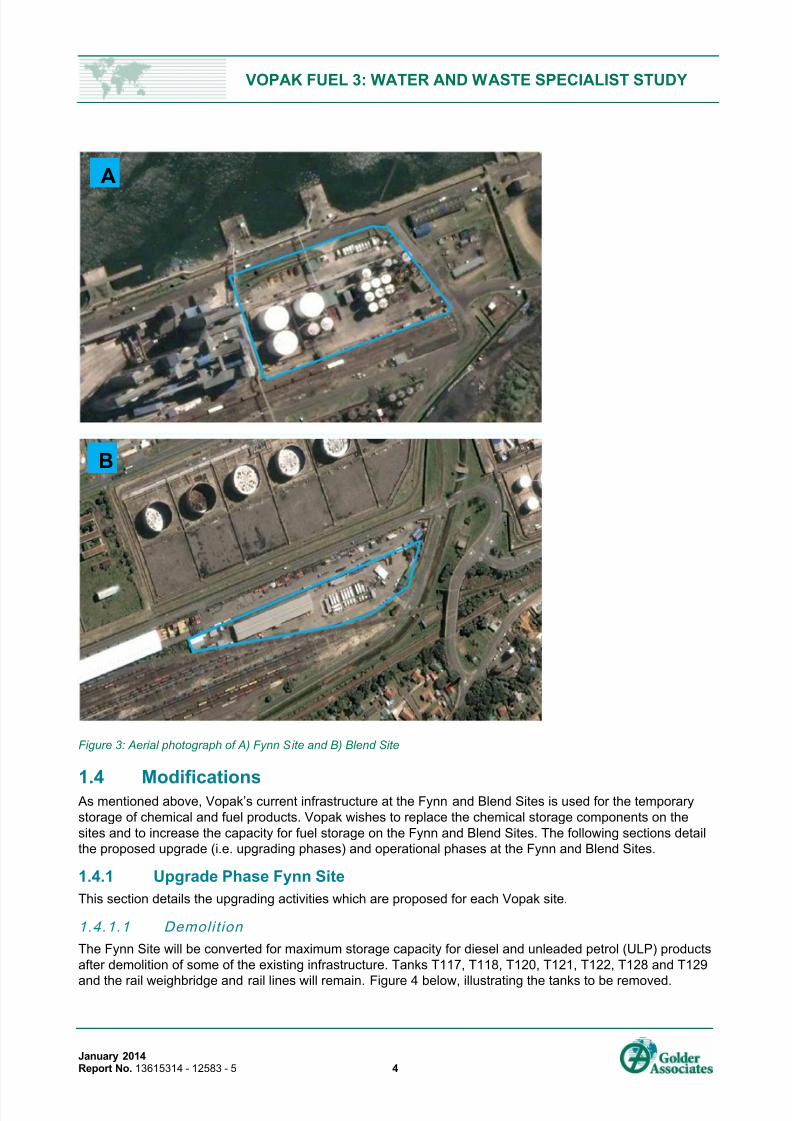
Table 3: Trade effluent heavy metal limits for the acceptance of discharge into the sewage disposalsystem
Heavy Metal Limits Large Works
(>25,000m3 /day)
Small Works
(<25,000m3 /day)
Copper 50 mg.l-1
5 mg.l-1
Nickel 50 mg.l-1
5 mg.l-1
Zinc 50 mg.l-1
5 mg.l-1
Iron 50 mg.l-1 5 mg.l-1
Boron 50 mg.l-1
5 mg.l-1
Selenium 50 mg.l-1
5 mg.l-1
Manganese 50 mg.l-1
5 mg.l-1
Lead 20 mg.l-1
5 mg.l-1
Cadmium 20 mg.l-1
5 mg.l-1
Mercury 1 mg.l-1
1 mg.l-1
Total Chrome 20 mg.l-1
5 mg.l-1
Arsenic 20 mg.l-1
5 mg.l-1
Titanium 20 mg.l-1
5 mg.l-1
Cobalt 20 mg.l-1
5 mg.l-1
Total Metals 100 mg.l-1
20 mg.l-1
The special limitations listed in Schedule A of the Sewage Disposal Bylaws:
1. No calcium carbide, radioactive waste or isotopes
2. No yeast and yeast wastes, molasses spent or unspent
3. No cyanides or related compounds capable of liberating HCN gas or cyanogen

7/25/2019 13615314 Vopak Fuel 3 Waste Water Study
http://slidepdf.com/reader/full/13615314-vopak-fuel-3-waste-water-study 19/34
VOPAK FUEL 3: WATER AND WASTE SPECIALIST STUDY
January 2014Report No. 13615314 - 12583 - 5 15
4. No degreasing solvents, petroleum spirit, volatile flammable solvents or any substance which yields a
flammable vapour at 21°C
3.1.2.2 Impl icatio ns for Vopak
Section 4.4 of the Sewage Disposal By-Laws (Municipal Notice No. 27 of 1999) has a bearing on Vopak’s
proposed upgrade project. Should the development result in the production of additional waste for release
into the sewage disposal system, there may be difficulties in gaining permission for discharge because the
municipal pump station which removes waste from the Cutler Complex is currently operating close to full
capacity (Pers. Comm. Sibusiso Shange – Pollution Division, eThekwini Metropolitan Municipality; Pers.
Comm. Soobs Moonsamy – Head of Development Planning, eThekwini Metropolitan Municipality).
The proposed upgrade project will inevitably result in a change in the proportions of wastes contained within
the effluent produced. The product profile is expected to be significantly modified as the facilities will be used
to better service the petrochemical market, and move away from the specialty chemical market. Therefore in
terms of Section 4.11 Vopak must apply to the Municipality to change the composition of its trade effluent.
The trade effluent discharged from the Vopak facilities needs to comply with all the limits stated in Schedule
A. in terms of Section 4 of the special limitations, Vopak must ensure that the trade effluent does not contain
BTEX (Benzene, Toluene, Ethyl-benzene and Xylene).
The Municipality tests samples of Vopak’s treated effluent on a monthly basis to assess compliance with the
limits in Schedule A.
Vopak discharges trade effluent to the Southern Wastewater Treatment Works. This facility has the capacity
to treat greater than 25,000 m³/day, and therefore the limits listed under Large Works apply to Vopak.
3.1.3 National Environmental Management Integrated Coastal Management Act
Chapter 8 of the National Environmental Management: Integrated Coastal Management Act (Act No. 24 of
2008) (NEM: ICMA) deals with Marine and Coastal Pollution Control, and Section 69 deals specifically withthe Discharge of effluent into coastal waters. Section 69 states that:
(1) No person may discharge effluent that originates from a source on land into coastal waters except in
terms of a general authorisation contemplated in subsection (2) or a coastal waters discharge permit
issued under this section by the Minister after consultation with the Minister responsible for water
affairs in instances of discharge of effluent into an estuary.
Note: activities associated with a general authorization have to date note been published.
Vopak proposes making use of water abstracted from the Port of Durban for the hydrostatic testing of
storage tanks (once constructed), and are currently in discussion with the Department of Water Affairs in this
regard with the plan to be submitted to the authorities prior to permission being granted.
3.2 National Environmental Management Waste ActChapter 4 of the National Environmental Management Waste Act (Act No. 59 of 2008) (NEM:WA) deals with
Waste Management Measures, while Part 2 deals with General Duty, and Section 16 deals with general
duties in respect of waste management. Chapter 4, Part 2, Section 16 states that:
(1) A holder of waste must, within the holder’s power, take all reasonable measures to –
(a) avoid the generation of waste and where such generation cannot be avoided, to minimize the
toxicity and amounts of waste that are generated;
(b) reduce, re-use, recycle and recover waste;
(c) where waste must be disposed of, ensure that the waste is treated and disposed of in an
environmentally sound manner;

7/25/2019 13615314 Vopak Fuel 3 Waste Water Study
http://slidepdf.com/reader/full/13615314-vopak-fuel-3-waste-water-study 20/34
VOPAK FUEL 3: WATER AND WASTE SPECIALIST STUDY
January 2014Report No. 13615314 - 12583 - 5 16
(d) manage the waste in such a manner that it does not endanger health or the environment or
cause a nuisance through noise, odour or visual impacts;
(e) prevent any employee or any person under his or her supervision from contravening this Act; and
(f) prevent the waste from being used for an unauthorized purpose.
Chapter 5 of NEM:WA deals with Licensing of Waste Management Activities, and Section 45 deals with
Application for Waste Management Licenses. Chapter 5, Section 45 states that:
(1) A person who requires a waste management license must apply for the license by lodging an
application with the licensing authority.
(2) An application for a waste management license must be accompanied by –
(a) the prescribed processing fee; and
(b) such documentation and information as may be reasonably required by the licensing authority.
In July 2009 the Minister of Environmental Affairs published a list of scheduled waste management activities
in accordance with Section 19 (1) of NEM:WA, while an amended list of waste management activities was
published in November 2013. Under the amended list of waste management activities, activities listed under
Category A require the completion of a Basic Assessment (BA) process prior to commencement; while
activities listed under Category B require a full Scoping and Environmental Impact Assessment (S&EIA)
process; and activities listed under Category C require compliance with the relevant requirements or
standards determined by the Minister which include the Norms and Standards for Storage of Waste (2013);
Standards for Extraction, Flaring or Recovery of Landfill Gas (2013); or Standards for Scrapping or Recovery
of Motor Vehicles (2013). Waste management activities which may be associated with the proposed
development are listed below:
Category A:
(8) The remediation of contaminated land.
If the presence of the tanks that are to be demolished has led to contamination and this is required to be a
remediated then a waste management license may be required.
3.2.1 Vopak’s Soil and Groundwater Remediation
As part of its soil and groundwater remediation work Vopak first installed monitoring wells on its Durban sites
in 1996 in order to better understand the level of contamination at these sites. At the time of installing the
wells no free phase product was encountered. Vopak elected to continue with the annual monitoring of the
wells and adopted a Monitored Natural Attenuation (MNA) remedial approach. Since then Vopak has
expanded on this with further investigations on its sites, and also participates in the Transnet National Port
Authorities (TNPA) Cutler Complex Consolidated Groundwater Monitoring Programme. A committee wasestablished to address the issue of groundwater monitoring comprising of representatives from the Port,
relevant authorities and companies within the complex, which includes Vopak.
As required by law and in line with its Soil and Groundwater Standard Vopak developed a strategy and
remediation management plan for groundwater and soil remediation on its site. This strategy and
remediation management plan has been communicated to and approved by the relevant authorities.
Continual progress updates are provided to the authorities to ensure alignment with the complex, and to the
objectives as developed by authorities.
The soil and remediation plan and remediation work on the Vopak Sites pre-dates the legislative
requirements of NEM:WA for a waste license, and hence no waste license is required. This has been
confirmed with the authorities through various forums and engagements. Continued future engagement with
the authorities is ensured to continue to align the methods of remediation as acceptable to achieving theremedial objectives during construction activities.

7/25/2019 13615314 Vopak Fuel 3 Waste Water Study
http://slidepdf.com/reader/full/13615314-vopak-fuel-3-waste-water-study 21/34
VOPAK FUEL 3: WATER AND WASTE SPECIALIST STUDY
January 2014Report No. 13615314 - 12583 - 5 17
The Fuel 3 project aligns with the strategy and plans for the management and remediation of soil and
groundwater on the Vopak Sites. Furthermore it is expected that the Fuel 3 project will speed up some of the
soil and groundwater remediation work being undertaken by Vopak, in that the areas affected byconstruction will be prioritized to ensure that suitable remediation objectives (agreed with the relevant
authorities) are achieved during construction.
3.3 Evaluation of Water and Waste Impacts of Vopak’s CurrentOperations
3.3.1 Water Use
The eThekwini Water and Sanitation Unit (EWS) provides Vopak with potable water for its operations, via a
connection to the water mains. Over the period January 20012 – June 2013, the average monthly potable
water usage was ~816 m ³.
Tank and line washing activities constitute the most significant components of Vopak’s current operational
water demands. The current water volumes required for washing activities would be significantly higher wereit not for Vopak’s pigging operations. Pigs are used between product movements in multi-purpose pipelines
to return product remaining in the line to the tank for storage. Water is then required to remove the residue
and avoid contamination across products that are being handled. Furthermore, planning of product
movement in the mulit-product lines is done to schedule compatible products where no washing between
product movements is required further preventing the production of wastewater. Unlike multi-purpose lines,
dedicated lines are only washed when under maintenance conditions. Similarly the washing of storage tanks
is also only undertaken when tanks are emptied for maintenance purposes and/or when the product stored in
a tank is changed as per customer requests. Other activities requiring water include, general cleaning
purposes and ablutions.
3.3.2 Wastewater Streams
The following main wastewater streams can be identified as being generated at the Fynn and Blend Sites:
3.3.2.1 Non co ntam inated rainwater
Non-contaminated rainwater (i.e. rainwater from roof structures etc.) will run off into the storm water drainage
system on site. Rainwater runoff from parking and roads within the facility is considered to be non-
contaminated and will be directed into the storm water drains on site.
3.3.2.2 Oily/hyd rocarb on/organic waste
This liquid waste consists of different streams, namely:
Diluted tank cleaning waste,
Contaminated rainwater from the pump bay areas,
Contaminated rainwater from the loading bay areas,
Contaminated rainwater from the additive off-loading bay areas.
These waste streams will be sent to the separator system and holding tank for testing and treatment as
required, and/or released based on results of the water quality testing.
3.3.2.3 Rainwater from tank pits
Rainwater from tank pits is considered to be non-contaminated rainwater. For this reason all tank pits are
designed as closed systems, to ensure minimal possibility of contamination on site. However in the case of a
leakage or spill this will no longer be the case. In the event of a spill, this would be treated as an incident. If
no contaminants are present then the rainwater can be discharged to stormwater drains. If contaminants are
present in the rainwater, it needs to be transferred to the separator system and holding tank for further
analysis and treatment accordingly.

7/25/2019 13615314 Vopak Fuel 3 Waste Water Study
http://slidepdf.com/reader/full/13615314-vopak-fuel-3-waste-water-study 22/34
VOPAK FUEL 3: WATER AND WASTE SPECIALIST STUDY
January 2014Report No. 13615314 - 12583 - 5 18
3.3.2.4 Tank cleanin g was te
Normal tank cleaning waste is re-used, recycled or sent for disposal as per legal requirements.
3.3.2.5 Spil ls /off sp ec pro du ct
Large spills and off spec product will be pumped directly to vacuum trucks for offsite processing. The number
and size of vacuum trucks required depends on the volume of spilled or off-spec product.
3.3.2.6 Sani tary waste
Sanitary waste consists of wastewater coming from sanitary facilities such as showers, wash basins and
toilets but also wastewater coming from the office facilities. This wastewater will be disposed into the
municipal sewer system.
3.3.3 Waste
This section highlights the sources of waste generated on Vopak’s site as a result of their operations and
details the procedures currently used to handle and treat each.
3.3.3.1 Tank and Lin e Wash ing s
Vopak’s Fynn and Blend sites comprise a network of storage tanks and pipelines which are used for the
storage and handling of different products. Different products are associated with different logistical
requirements. Vopak’s network of tanks and pipelines enables the transfer of product between the different
sites, and also connects the berths to the sites. There are also pipelines within each site which are
responsible for connecting the various storage tanks and loading gantries.
Liquid waste generated during tank and line washing (see Section 3.3.1 above) is considered to be
hazardous, and is re-used, recycled or treated at an offsite facility capable of handling the volumes of
washings produced. Washings are decanted and stored in slop tanks or waste tubes until such time as they
are collected and disposed of by a suitable waste contractor. Slop tanks are fixed units, tubes are mobileunits provided by the service provider, used for the temporary storage of waste. Upon collection waste is
pumped from the slop tanks into a permitted contractor’s tanker for collection and disposal. Certificates of
cleanliness and safe disposal are kept on file.
3.3.3.2 Slops
Particularly for chemicals, the quality criteria for the products are very specific and product can be
considered ‘off -spec’ during the normal product transfer process. End of line samples are done prior to
loading a vessel or tank and if considered off specification, the surveyor / customer requests a certain
volume to be ‘slopped’ where the initial incoming product is transferred into drums for temporary storage, re-
use, recycling or disposal as determined by the customer.
During the slopping of incoming product, tests are administered to determine the quality of the incoming
product. Once the tests being administered verify that the incoming product is above the applicable qualitythreshold (i.e. the product is “on-specification”), the product is loaded into the intended tank or vessel for
storage. The respective customer will then remove the slop drums from the Vopak sites for re-use back into
the production process, recycling or disposal as required.
Samples taken to ensure product is ‘on-specification’ during the movement and storage of product is a
source of waste. This is disposed of as ‘drainings’ into slop drums and removed by an approved waste
contractor. Samples taken by independent surveyors are handled and disposed by themselves.
3.3.3.3 Operatio nal Areas
Handl ing
In certain bunded operational areas, such as at pipe interchanges, pig insertion/extraction points, pump bays
and manifolds spills are an anticipated waste source.

7/25/2019 13615314 Vopak Fuel 3 Waste Water Study
http://slidepdf.com/reader/full/13615314-vopak-fuel-3-waste-water-study 23/34
VOPAK FUEL 3: WATER AND WASTE SPECIALIST STUDY
January 2014Report No. 13615314 - 12583 - 5 19
Waste generated in the bunded operational areas at Vopak’s Fynn and Blend Sites, is diverted to an onsite
separator system. At the separator, oils are skimmed from the surface of the effluent and certain solids are
allowed to settle to the bottom. Skimmed oils are then stored in drums, which are collected by contractors forrecycling. The remaining effluent is then pumped into a storage tank where the volume of stored waste can
be monitored. Tests are undertaken on the stored effluent to determine its quality. If the relevant quality
specifications are met (i.e. the effluent is established to be ‘clean’), the water will be released to the Port of
Durban. However if the specifications are not met, a tanker is used to collect the stored effluent for treatment
at the Farewell site wastewater treatment facility.
First Flush
The first flush of storm water that falls within the operational areas is considered to be ‘dirty’. This wastewater
is diverted to the onsite separators. Following the collection of the first flush (comprising approximately 20
tons), all subsequent stormwater is considered rainwater (i.e. ‘clean’) and is released to the bay via the storm
water drainage system.
Each bund in the sites operational areas have a drainage valve which is controlled. During rain events, thewater that accumulates in the bunded areas is firstly verified as rainwater, prior to being released into the
bay.
Trade Effluent
Trade effluent generated by Vopak’s sites is collected in on-site separator systems. Once the trade effluent
has been deemed to be of acceptable quality for release, it is discharged from Vopak into the effluent
discharge system based in the Cutler Complex.
Trade effluent released into the effluent discharge system from the various companies in the Cutler Complex
is pumped from the Transnet owned pump station to a large pump station run by the eThekwini Water and
Sanitation Unit (EWS) located in Fynnland. The effluent is then pumped along the connecting sewer (known
as the Badulla Line) to the Southern Wastewater Treatment Works.
Scrubb er Solut ion
Vopak currently utilizes scrubber technology to control some emissions from its sites. Waste in the form of
spent solution is generated as a by-product of the treatment process. The nature (odour/volatility) of the
stored chemical determines which solution is to be used in emission abatement.
Waste generated from the scrubbers is either recycled or removed and treated by the appropriate waste
management contractor.
Boiler
A Heavy Fuel Oil (HFO) Boiler operates on a batch system at Vopak’s Fynn Site to maintain the temper ature
of certain tanks. No waste products requiring disposal are produced as a result of the combustion process
Air emissions resulting from the boiler are addressed in the Air Quality impact assessment.
Sewage
Sewage produced at the Fynn Site is pumped to the sewage treatment works via the established sewage
reticulation system. Vopak’s Blend Site is however not connected to the sewage system; and as a result
sewage generated at this site is removed by the appropriate waste contractor.
3.3.3.4 Emerg ency Waste
Spil ls
Unanticipated spills in the form of tank and tanker overfills have occurred at Vopak’s sites in the past. The
procedure in responding to a spill/leak of manageable volume, involves taking action to stop the source of
the spill/leak, and containing the spill/leak by use of spill equipment. If there is a fire risk or a need to control
vapours foam may be used to blanket the spill. Absorbents and neutralizers are used in responding to a spillas required. Once the spill has been confirmed to be safe, Vopak’s spill response equipment is used to pump
the spilled product into a mobile slop drum, which is then stored on site until it is removed by a contractor. A

7/25/2019 13615314 Vopak Fuel 3 Waste Water Study
http://slidepdf.com/reader/full/13615314-vopak-fuel-3-waste-water-study 24/34
VOPAK FUEL 3: WATER AND WASTE SPECIALIST STUDY
January 2014Report No. 13615314 - 12583 - 5 20
spill response company is on standby as part of Vopak’s emergency response to ensure large scale events
are prepared for.
Where quality specifications permit, spilt product will be recovered. However if foam, neutralizers orabsorbents were used to handle the spill, recycling is not feasible, and the waste is treated and disposed of
in the appropriate manner.
Records of all spills are kept as part of the Health, Safety and Environmental Key Performance Indicator
(KPI) requirements..
Major Incidents
In the event of a major incident occurring, spilt product would collect in the concrete tiled bund surrounding
the tank, thereby preventing the lateral spread of the spilt product. Due to the fact that some of Vopak’s bund
floors (on Blend) are not fully concreted and therefore do not provide an impermeable barrier, the possibility
exists that spilt product may pollute the soil and groundwater. The prevention of the potential for soil and
groundwater contamination is one benefit of the proposed upgrade project. As a result, fully concreted bundfloors are planned for the project.
If a major incident in the form of a tank fire or the loss of containment were to occur, the Emergency
Response Procedure would be activated to bring the situation under control. Firefighting and/or inter-bund
drainage may be required. In both cases significant amounts of waste would be produced (product mixed
with firewater). Liquid waste removal contractors would be brought in to remove the waste from the site and
undertake the necessary treatment. The waste generated would be treated offsite at a facility with sufficient
capacity to treat such large volumes.
3.3.3.5 Sol id Was te
Hazardous
Foam pigs used in pigging operations are a source of hazardous solid waste. During pigging, the pigs
become saturated with product and are therefore handled and treated as hazardous waste.
Used pigs are firstly wrapped in a black plastic bag to ensure that no product leaks. The bag is then placed
in a two-lidded bin, which is collected by an approved waste contractor. Certificates of the safe disposal of
solid waste removed from the sites are kept on file.
Non-Hazardous
There are a variety of non-hazardous solid wastes generated at Vopak’s sites. These include wood (e.g.
scrap pallets), paper and cardboard or similar materials generated by offices, storage and infrastructure,
plastic, metal, polystyrene food container, domestic waste from kitchens and waste bins and garden refuse.
Non-hazardous solid waste is temporally stored on site and the removed by the appropriate waste handling
company (see Table 4).
Table 4: Procedure for the handling of non-hazardous solid waste at Vopak's Fynn and Blend Sites.
Waste Source Handling
Wood (e.g. scrap pallets) Stored at location designated for collection by contractor.
Paper and cardboard Recycled. Stored at location designated for collection by contractor.
Plastic Recycled. Stored at location designated for collection by contractor.
Metal Recycled. Stored at location designated for collection by contractor.
Polystyrene Placed in a general waste skip.
Garden Refuse Taken to landfill.
3.3.4 Overview of Vopak’s Waste Handling Philosophy Vopak’s general waste handling philosophy for the proposed project can be summarised as follows:

7/25/2019 13615314 Vopak Fuel 3 Waste Water Study
http://slidepdf.com/reader/full/13615314-vopak-fuel-3-waste-water-study 25/34
VOPAK FUEL 3: WATER AND WASTE SPECIALIST STUDY
January 2014Report No. 13615314 - 12583 - 5 21
3.3.4.1 Was te Water
Non-contaminated water (i.e. non-contaminated rainwater) is connected to internal storm water drains that
feed to the onsite oil/water separator and then to a clean water sump. Film detection will be present in allsumps. Slightly contaminated water will be sent via the onsite separator to a holding tank. Vopak will install a
BTEX sampler to detect BTEX which will be tested, and each batch will be sampled to verify the results. If
the tested water is not contaminated, the water will be released into the bay, while contaminated water is
sent to a wastewater treatment plant (WWTP) on the Farewell-King site.
3.3.4.2 New Separators Design s
Waste water that would be released into the Fynn Site separator facility is from the following areas:
Fynn site pump bay area = 477 m²
Fynn site loading bays = 255 m²
Fynn site offloading bays = 48 m²
The upgrade of the separator facility at Vopak’s Fynn site will therefore be able to accommodate waste water
runoff from an area of 780 m².
Waste water that would be released into the Blend Plant separator facility is from the following areas:
Blend Plant pump bay area = 126 m²
Blend Plant loading bays = 1300 m²
Blend Plant offloading bays = 192 m²
Blend Plant washing bays = 10 m²
The upgrade of the separator facility at Blend Plant will therefore be able to accommodate the waste water
runoff from an area of 1628 m².
3.3.4.3 Vapou r Hand ling
In order to prevent unnecessary discharge of vapours to the atmosphere Vopak proposes installing Internal
Floating Roofs on tanks containing petroleum-based products, and Vapour Recovery systems at truck
loading points.
Tanks containing petroleum-based products will be fitted with Internal Floating Roof ’s to minimise vapour
loss during the filling and emptying of tanks. As a result no vapour handling system would be required for the
storage tanks.
A Vapour Recovery/ Treatment System will be installed at the truck loading to treat the vapour emissions
during loading of trucks with petrol. If a recovery technology is preferred, the unit system will be located close
to the loading gantry and will include storage vessels for the recovered fuel. Fuel recovered from the Vapour
Recovery System will be returned to the respective storage tank. The design capacity of the new vapour
treatment system would be based on 6 road tanker filling units (4 current and 2 future) operating
simultaneously.
3.3.4.4 Sol id Was te
Solid waste generated on site will be sorted, collected, and despatched. Containers for solid waste will be
sign posted and colour coded to determine the type of waste.
Paper waste and similar wrapping materials are generated by offices, storage and infrastructure. This waste
is deposited into dedicated bins then transferred to 7 m³ skips located in a defined area adjacent to the site.The skip will be removed on a weekly basis by a recognised waste disposal company for off-site recycling.

7/25/2019 13615314 Vopak Fuel 3 Waste Water Study
http://slidepdf.com/reader/full/13615314-vopak-fuel-3-waste-water-study 26/34
VOPAK FUEL 3: WATER AND WASTE SPECIALIST STUDY
January 2014Report No. 13615314 - 12583 - 5 22
During construction the skip may require removal more frequently when packaging materials are disposed of
and this will be on demand.
Material waste such as contaminated cloth towelling generated during the construction phases andthereafter by maintenance and sanitation, will be collected in dedicated bins located strategically around the
construction site. The bins will be emptied into an 11 m³ skip adjacent to the construction site, and thereafter
adjacent to the main site store/workshop. The skip will be removed on a weekly basis by a recognised waste
disposal company for off-site disposal/incineration.
Food and domestic waste generated from the kitchens, canteen and office waste bins will be collected in
bins then transferred to skips located in a defined area adjacent to the site. The skip sizes will be
approximately 7 m³ during construction and upon terminal operation. The skip will be removed on a bi-
weekly basis by a recognised waste disposal company for off-site recycling.
3.3.5 Identification of Waste Sources during Upgrading and Operations
3.3.5.1 WastewaterDuring upgrading wastewater will be generated as a result of tank cleaning. Storage tanks will be emptied of
product as part of the completion of the customers contract (through product dispatch) and the empty tanks
will then be washed. The tank washings generated as a result of this process will be treated as hazardous
waste. Washings will be stored in waste tubes tanks and removed and treated by an approved contractor at
the appointed time. Wastewater from tanks containing petroleum-based products will be recycled.
During operations wastewater will be generated as a result of tank and line washing, and ablution facilities as
discussed previously.
3.3.5.2 Sol id Was te
Solid inert waste in the form of concrete rubble, unused concrete and cement will be produced as a result of
upgrading activities. These will be removed from the site and disposed of in an approved manner.Construction material in the form of piping off-cuts, unused tank strakes, reinforced steel, cable and plastic
sleeves, and welding rod ends will also remain after construction. Construction materials in an unused
condition will be re-sold, and materials that cannot be re-sold will be sold as scrap or discarded by an
approved contractor
Decommissioning of tanks as part of the upgrading process requires emptying them of their contents.
Product will either be transferred to alternative tanks or transported to the customer, taking the correct
environmental measures, however no product will be disposed of. Empty tanks will then be washed and gas-
freed to required specifications. Empty, washed tanks would then need to be certified ‘clean’ by an
independent consultant. Tanks that have been certified by an independent surveyor to be clean will be
stripped of all their accessories and will either be re-sold or cut up and sold as scrap metal
If residues have formed on the inner surface of the tank, cutting of the metal cannot occur until the residue isremoved, as this may risk the health and safety of the team undertaking the decommissioning. Should no
cleaning techniques be found suitable, the tank will be disposed of in a hazardous landfill site. Disposal of
tanks to landfill is however considered to be a last resort.
3.3.5.3 Slops
Slops will continue to be generated as part of Vopak’s operations; however the volume of slops likely to be
generated will be reduced as a result of the proposed upgrade project. A reduction in the range of products
stored (especially the range of speciality products such as chemicals stored) implies that fewer products with
significantly differing or high quality specifications will be handled and stored. In addition, dedicated systems
will be built, and movements between diesel and ULP will be done in a manner not to have to wash lines
inbetween movements, As a result the risk for contamination between products and the need for slopping is
eliminated. This is due to the fact that the proposed upgrade project will decrease the storage capacity ofchemicals which have more specialised storage and handling requirements, and increase the storage
capacity of fuels which are less sensitive to contamination than chemicals.

7/25/2019 13615314 Vopak Fuel 3 Waste Water Study
http://slidepdf.com/reader/full/13615314-vopak-fuel-3-waste-water-study 27/34
VOPAK FUEL 3: WATER AND WASTE SPECIALIST STUDY
January 2014Report No. 13615314 - 12583 - 5 23
3.3.5.4 Waste generated from op eration al areas
As part of the upgrade project it is proposed that a first flush be collected at Vopak ’s Fynn and Blend sites.
The first flush would result in the collection of the first approximately 20 tons of storm water to fall withinVopak’s operational areas. Once deemed to be within acceptable standards, the effluent will then be
discharged to the municipal sewer system.
Waste in the form of leaks and spills can be expected as part of maintenance in bunded areas such as pipe
interchanges, pig insertion/extraction points, pump bays and manifolds. Leaks and spills will be handled and
treated in the same manner in which they currently are (see Section 3.3.3.3). Effluent from operational areas
will be diverted to the onsite separators for testing prior to discharge or treatment (depending on the quality
of the effluent). If deemed unsuitable for release effluent generated from the operational areas will be
decanted into slop tanks for storage and removal by the appropriate contractor.
3.3.5.5 Waste from emissio ns abatement techno logy
As part of the upgrade project Vopak will be utilizing inner floating roofs (to minimise the production of
vapours) and vapour recovery technology for the loading facilities for petrol. The volume of waste generated
during emissions abatement will therefore be lower than that generated using different technologies such as
scrubber technology (which is currently used for chemicals).
Whereas scrubbers require that the spent solution be disposed of periodically, the activated carbon bed
associated with the proposed vapour recovery technology only needs to be replaced every three to five
years. The selected technology will therefore minimise the volume of waste to be produced to the greatest
extent.
3.3.5.6 Sewage
The volumes of sewage generated at Vopak are not expected to change as a result of the proposed upgrade
project. Sewage will be handled and treated in the manner in which it is currently (see Section 3.3.3.3).
3.3.6 Emergency Wastes
While the generation of emergency waste cannot be anticipated or measured, the tanks and associated
infrastructure will be constructed to the current best industry standards, which will improve the safety of the
operations, thereby reducing the potential of an incident occurring.
3.3.6.1 Spills
The proposed infrastructure will be constructed to the best industry standards, and will make use of the best
available technology. The loading at the new gantries will occur via an automated loading arm with interlocks
to reduce the risk of overfill. Scheduled batch loading will also be undertaken. These improvements will
significantly reduce the risk of overfill during loading, thus lowering the potential for spills.
In the event of a spill, the current spill response procedure will continue to be followed (see Section 3.3.3.4).
Where possible, spills of petroleum-based products will be recycled.
3.3.6.2 Major Inciden ts
The tank alignment proposed under the upgrade project will improve the firefighting capacity for those
responding to incidents at Vopak’s Fynn and Blend Sites. Reduced response time could diminish the amount
of emergency waste produced.
The existing emergency response procedures for unanticipated waste generation will be followed under the
proposed upgrade project (see Section 3.3.3.4).
3.4 Overview of Waste Minimisation measures proposed by Vopak
The following waste minimisation and recycling measures have been proposed as part of Vopak’s proposed
upgrade project. Implementation of such measures are intended to reduce Vopak’s impact on water use andwaste generation; and ensure the optimal functioning of the proposed sites:

7/25/2019 13615314 Vopak Fuel 3 Waste Water Study
http://slidepdf.com/reader/full/13615314-vopak-fuel-3-waste-water-study 28/34
VOPAK FUEL 3: WATER AND WASTE SPECIALIST STUDY
January 2014Report No. 13615314 - 12583 - 5 24
To design the facility in a manner to not produce waste as far as practically possible, by separating
‘clean’ and ‘dirty’ operational areas and addressing dirty wastewater through the separator and waste
water treatment system as required.
Where possible, spills of petroleum-based products and similarly wastewater derived from tanks
containing petroleum-based products are recycled. Due to the fact that the recycling of spilt chemicals
or wastewater derived from chemical tanks is not always possible Vopak’s proposed decrease in
storage capacity of chemicals and proposed increase in storage capacity of petroleum-based products
will result in greater opportunities for recycling to occur onsite.
By dedicating lines to certain products, the need for regular washing and pigging is greatly reduced.
Therefore, less waste water produced and fewer pigs will be utilized. Therefore the quantity of
hazardous liquid and solid waste generated during the operations phase is likely to decrease
subsequent to the proposed upgrade development
Non-hazardous solid waste generated onsite such as paper and cardboard, plastic and metal arecollected and stored onsite for collection by a contractor for recycling purposes.
In terms of emissions abatement equipment, Vopak’s current scrubbers will be removed from the site as
part of the upgrade (due to the removal of the handling of those specific chemicals), which is associated
with waste generation in the form of spent solution. The petrol loading will require a Vapour recovery
system which will result in reduced waste generation during Vopak’s operations.
During the upgrading process unused construction materials will be re-sold, and those materials that
cannot be re-sold will be sold as scrap or discarded by an approved contractor.
Tanks that have been certified by an independent surveyor to be clean will be stripped of all their
accessories and will either be re-sold or cut up and sold as scrap metal.
Vopak’s proposed increased use of dedicated lines over multi-purpose lines will reduce water
requirements for line washing (and the resultant production of wastewater) during the operations phase
due to the fact that no washing would be required between movements.
A reduction in the total number of tanks to be operated and maintained; and a reduction in the range of
chemicals to be handled, would also result in a reduction of water requirements as part of the upgrade
project.
Vopak’s proposal to make use of seawater abstracted from the Durban Harbour for hydro-testing
constructed tanks would reduce the volume of potable water required as part of the upgrade project.
The construction of fully concreted bund flooring as opposed to concrete tiled bunds will create an
impermeable barrier to spilt liquids and in doing so reduce the potential for soil and groundwatercontamination as a result of spills during Vopak’s operations.
3.5 Identification and Evaluation of Impacts
This section outlines the methodology used to assess impacts associated with the prosed Project. Potential
positive and negative impacts associated with the proposed Project are also discussed.
3.5.1 Impact Assessment Methodology
Impacts associated with the proposed project were assessed according to their Magnitude, Duration, Scale
and Probability of occurrence. These terms are briefly described below.
The following factors and criteria have been used to assess the impacts of the project.
7/25/2019 13615314 Vopak Fuel 3 Waste Water Study
http://slidepdf.com/reader/full/13615314-vopak-fuel-3-waste-water-study 29/34
VOPAK FUEL 3: WATER AND WASTE SPECIALIST STUDY
January 2014Report No. 13615314 - 12583 - 5 25
MAGNITUDE DURATION
10 - Very high/don’t know 5 – Permanent (longer than 10 years)
8 – High4 – Long-term (7 to 10 years; impact ceases after site
closure has been obtained)
6 – Moderate3 – Medium-term (3 months to 7 years; impact ceases afterthe operational life of the activity)
4 – Low2 – Short-term (0 to 3 months; impact ceases after theconstruction phase)
2 – Minor 1 – Immediate
SCALE PROBABILITY
5 – International 5 - Definite/don’t know
4 – National 4 - Highly probable
3 – Regional 3 - Medium probability
2 – Local 2 - Low probability
1 - Site only 1 – Improbable
0 – None 0 – None
Significance Points (SP)= (Magnitude + Duration + Scale) x Probability
Therefore:
SP >60 Indicates high
environmental
significance
An impact which could influence the decision about whether or not to
proceed with the project regardless of any possible mitigation.
SP 30 – 60 Indicates moderate
environmental
significance
An impact or benefit which is sufficiently important to require management
and which could have an influence on the decision unless it is mitigated.
SP <30 Indicates low
environmental
significance
Impacts with little real effect and which will not have an influence on or
require modification of the project design.
+ Positive impact An impact that is likely to result in positive consequences/effects.
4.0 RATING AND DICUSSION OF IMPACTS
4.1.1 Increased water use during upgrading activities
Decommissioning of storage tanks requires emptying them of products. Empty tanks will then need to be
washed before being removed from site. Hydro-testing of tanks to confirm their integrity will require large
quantities of water. In addition, water will be required for construction activities such as mixing of concrete,
system hydrostatic testing and for domestic purposes High water use presents an impact of moderate
environmental significance. Vopak however proposes to make use of seawater abstracted from the Durban
Harbour for hydro-testing constructed tanks. Such an approach will effectively reduce the volume of potable
water required, and the environmental significance of the impact is reduced to low. This is currently being
discussed with the relevant authorities.
4.1.2 Generation of general waste during upgrading activities
General waste will be derived from construction workers on site, as well as wood and metal off cuts and
packaging waste from building activities. Solid waste in the form of concrete rubble will also be produced.
This will be removed from site and disposed of in an appropriate manner. It is highly unlikely that these
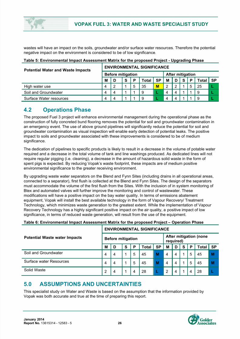
7/25/2019 13615314 Vopak Fuel 3 Waste Water Study
http://slidepdf.com/reader/full/13615314-vopak-fuel-3-waste-water-study 30/34
VOPAK FUEL 3: WATER AND WASTE SPECIALIST STUDY
January 2014Report No. 13615314 - 12583 - 5 26
wastes will have an impact on the soils, groundwater and/or surface water resources. Therefore the potential
negative impact on the environment is considered to be of low significance.
Table 5: Environmental Impact Assessment Matrix for the proposed Project - Upgrading Phase
Potential Water and Waste ImpactsENVIRONMENTAL SIGNIFICANCE
Before mitigation After mitigation
M D S P Total SP M D S P Total SP
High water use 4 2 1 5 35 M 2 2 1 5 25 L
Soil and Groundwater 4 4 1 1 9 L 4 4 1 1 9 L
Surface Water resources 4 4 1 1 9 L 4 4 1 1 9 L
4.2 Operations Phase
The proposed Fuel 3 project will enhance environmental management during the operational phase as theconstruction of fully concreted bund flooring removes the potential for soil and groundwater contamination in
an emergency event. The use of above ground pipelines will significantly reduce the potential for soil and
groundwater contamination as visual inspection will enable early detection of potential leaks. The positive
impact to soils and groundwater associated with these improvements is considered to be of medium
significance.
The dedication of pipelines to specific products is likely to result in a decrease in the volume of potable water
required and a decrease in the total volume of tank and line washings produced. As dedicated lines will not
require regular pigging (i.e. cleaning), a decrease in the amount of hazardous solid waste in the form of
spent pigs is expected. By reducing Vopak’s waste footprint, these impacts are of medium positive
environmental significance to the greater receiving environment.
By upgrading waste water separators on the Blend and Fynn Sites (including drains in all operational areas,connected to a separator), first flush is collected at the Blend and Fynn Sites. The design of the separators
must accommodate the volume of the first flush from the Sites. With the inclusion of in system monitoring of
Btex and automated valves will further improve the monitoring and control of wastewater. These
modifications will have a positive impact on the bay water quality. In terms of emissions abatement
equipment, Vopak will install the best available technology in the form of Vapour Recovery/ Treatment
Technology, which minimizes waste generation to the greatest extent. While the implementation of Vapour
Recovery Technology has a highly significant positive impact on the air quality, a positive impact of low
significance, in terms of reduced waste generation, will result from the use of the equipment.
Table 6: Environmental Impact Assessment Matrix for the proposed Project – Operation Phase
Potential Waste water Impacts
ENVIRONMENTAL SIGNIFICANCE
Before mitigation After mitigation (nonerequired)
M D S P Total SP M D S P Total SP
Soil and Groundwater 4 4 1 5 45 M 4 4 1 5 45 M
Surface water Resources 4 4 1 5 45 M 4 4 1 5 45 M
Solid Waste 2 4 1 4 28 L 2 4 1 4 28 L
5.0 ASSUMPTIONS AND UNCERTAINTIES
This specialist study on Water and Waste is based on the assumption that the information provided by
Vopak was both accurate and true at the time of preparing this report.

7/25/2019 13615314 Vopak Fuel 3 Waste Water Study
http://slidepdf.com/reader/full/13615314-vopak-fuel-3-waste-water-study 31/34
VOPAK FUEL 3: WATER AND WASTE SPECIALIST STUDY
January 2014Report No. 13615314 - 12583 - 5 27
6.0 REFERENCES
1: Milieudefensie (Friends of the Earth, Netherlands), Chapter 3: Durban South Africa: Leaking
Pipelines and Accidents.
2: Behind the Shine, the Other Shell Report (2004), Friends of the Earth (England, Wales and Northern
Ireland). [http://www.foeeurope.org/corporates/pdf/study5.pdf]
3: The groundWork 2004 Annual Report (2004), groundWork.
[http://www.foeeurope.org/corporates/pdf/study5.pdf]
4: Gerretsen, B. (2007) Durban fire: Missing worker presumed dead, The Mercury , 20 September 2007,
pg 1.
5: Sutcliffe, M. (2007) Island View fire and the lessons learnt, The Metro, 5 October 2007, pg 7.
GOLDER ASSOCIATES AFRICA (PTY) LTD.
Golder – Rob Hounsome
Specialist – Water and Waste
Golder - Nelius Scheepers Golder – Ed Perry
Project Manager Project Reviewer
Associate / Divisional Leader of Environmental Services
Reg. No. 2002/007104/07
Directors: SAP Brown, L Greyling, RGM Heath
Golder, Golder Associates and the GA globe design are trademarks of Golder Associates Corporation.
\\dur2-s-fs3\gaadata\projects\13615314_vopak_fuel3\6_deliverables\6.1_reports\appendices\app d_spcial rprts\waste
water\13615314_vopak_fuel3_specialist_study_waterwaste_v8_ final.docx

7/25/2019 13615314 Vopak Fuel 3 Waste Water Study
http://slidepdf.com/reader/full/13615314-vopak-fuel-3-waste-water-study 32/34
VOPAK FUEL 3: WATER AND WASTE SPECIALIST STUDY
January 2014Report No. 13615314 - 12583 - 5 28
APPENDIX ADocument Limitations

7/25/2019 13615314 Vopak Fuel 3 Waste Water Study
http://slidepdf.com/reader/full/13615314-vopak-fuel-3-waste-water-study 33/34
VOPAK FUEL 3: WATER AND WASTE SPECIALIST STUDY
January 2014Report No. 13615314 - 12583 - 5 29
DOCUMENT LIMITATIONS
This Document has been provided by Golder Associates Africa Pty Ltd (“Golder”) subject to the following
limitations:
i) This Document has been prepared for the particular purpose outlined in Golder’s proposal and no
responsibility is accepted for the use of this Document, in whole or in part, in other contexts or for any
other purpose.
ii) The scope and the period of Golder’s Services are as described in Golder’s proposal, and are subject to
restrictions and limitations. Golder did not perform a complete assessment of all possible conditions or
circumstances that may exist at the site referenced in the Document. If a service is not expressly
indicated, do not assume it has been provided. If a matter is not addressed, do not assume that any
determination has been made by Golder in regards to it.
iii) Conditions may exist which were undetectable given the limited nature of the enquiry Golder wasretained to undertake with respect to the site. Variations in conditions may occur between investigatory
locations, and there may be special conditions pertaining to the site which have not been revealed by
the investigation and which have not therefore been taken into account in the Document. Accordingly,
additional studies and actions may be required.
iv) In addition, it is recognised that the passage of time affects the information and assessment provided in
this Document. Golder’s opinions are based upon information that existed at the time of the production
of the Document. It is understood that the Services provided allowed Golder to form no more than an
opinion of the actual conditions of the site at the time the site was visited and cannot be used to assess
the effect of any subsequent changes in the quality of the site, or its surroundings, or any laws or
regulations.
v) Any assessments made in this Document are based on the conditions indicated from published sourcesand the investigation described. No warranty is included, either express or implied, that the actual
conditions will conform exactly to the assessments contained in this Document.
vi) Where data supplied by the client or other external sources, including previous site investigation data,
have been used, it has been assumed that the information is correct unless otherwise stated. No
responsibility is accepted by Golder for incomplete or inaccurate data supplied by others.
vii) The Client acknowledges that Golder may have retained sub-consultants affiliated with Golder to
provide Services for the benefit of Golder. Golder will be fully responsible to the Client for the Services
and work done by all of its sub-consultants and subcontractors. The Client agrees that it will only assert
claims against and seek to recover losses, damages or other liabilities from Golder and not Golder’s
affiliated companies. To the maximum extent allowed by law, the Client acknowledges and agrees it will
not have any legal recourse, and waives any expense, loss, claim, demand, or cause of action, againstGolder’s affiliated companies, and their employees, officers and directors.
viii) This Document is provided for sole use by the Client and is confidential to it and its professional
advisers. No responsibility whatsoever for the contents of this Document will be accepted to any person
other than the Client. Any use which a third party makes of this Document, or any reliance on or
decisions to be made based on it, is the responsibility of such third parties. Golder accepts no
responsibility for damages, if any, suffered by any third party as a result of decisions made or actions
based on this Document.

7/25/2019 13615314 Vopak Fuel 3 Waste Water Study
http://slidepdf.com/reader/full/13615314-vopak-fuel-3-waste-water-study 34/34
Golder Associates Africa (Pty) Ltd.
PO Box 29391
Maytime, 3624
Block C, Bellevue Campus
5 Bellevue Road
Kloof, 3610
KwaZulu-Natal
South Africa
T: [+27] (31) 717 2790