Embed Size (px)
Citation preview
Application Note Please read the Important Notice and Warnings at the end of this document V 1.0
www.infineon.com/ref-5ar4770ag-13w1 page 1 of 39 2018-09-24
AN_1809_PL83_1810_045410
13 W non-isolated auxiliary power supply for
outdoor air-conditioner using ICE5AR4770AG
REF_5AR4770AG_13W1
About this document
Scope and purpose
This document is a reference design for a 13 W auxiliary power supply for an outdoor air-conditioner unit with
the latest fifth-generation Infineon Fixed-Frequency (FF) CoolSET™ ICE5AR4770AG. The power supply is
designed with a universal input compatible with most geographic regions, and two non-isolated outputs (+12
V/0.85 A, +15 V/150 mA) on a single-layer PCB. The PCB has a provision to add a linear regulator to support a third output (e.g. +5 V), which is connected to a +12 V output.
Highlights of the auxiliary power supply for the outdoor air-conditioner unit are:
Tightly regulated output voltages, high efficiency under light load and low standby power
Comprehensive protection feature CoolSET™ with integrated input Line Over Voltage Protection (LOVP) and
externally implemented brown-in protection (GATE pin resistor to GND)
Auto-restart protection scheme to minimize interruption and enhance end-user experience
Intended audience
This document is intended for power supply design engineers who are designing auxiliary power supplies for
outdoor air-conditioner units that are efficient, reliable and easy to design.
Table of contents
About this document ....................................................................................................................... 1
Table of contents ............................................................................................................................ 1
1 System introduction ............................................................................................................... 3
2 Reference board design .......................................................................................................... 5
3 Power supply specifications .................................................................................................... 6
4 Circuit diagram ...................................................................................................................... 7
5 Circuit description .................................................................................................................. 8
5.1 EMI filtering and line rectification ........................................................................................................... 8
5.2 Flyback converter power stage ............................................................................................................... 8
5.3 Control of flyback converter through fifth-generation FF CoolSET™ ICE5AR4770AG ........................... 8 5.3.1 Current sensing .................................................................................................................................. 8 5.3.2 Feedback and compensation network .............................................................................................. 8 5.4 Unique features of the fifth-generation FF CoolSET™ ICE5AR4770AG .................................................. 9
5.4.1 Fast self-start-up and sustaining of VCC ............................................................................................. 9 5.4.2 CCM, DCM operation with frequency reduction ................................................................................ 9 5.4.3 Frequency jittering with modulated gate drive ................................................................................ 9 5.4.4 System robustness and reliability through protection features ...................................................... 9 5.5 Clamper circuit ...................................................................................................................................... 10
5.6 PCB design tips ...................................................................................................................................... 10 5.7 EMI reduction tips ................................................................................................................................. 11
Application Note 2 of 39 V 1.0
2018-09-24
13 W non-isolated auxiliary power supply for outdoor air-conditioner
using ICE5AR4770AG REF_5AR4770AG_13W1 System introduction
6 PCB layout ............................................................................................................................ 12 6.1 Top side ................................................................................................................................................. 12
6.2 Bottom side ........................................................................................................................................... 12
7 BOM ..................................................................................................................................... 13
8 Transformer specification ...................................................................................................... 14
9 Measurement data and graphs ................................................................................................ 15
9.1 Efficiency curve...................................................................................................................................... 16 9.2 Standby power ...................................................................................................................................... 17
9.3 Line and load regulation ....................................................................................................................... 17 9.4 Maximum input power .......................................................................................................................... 18 9.5 Frequency reduction ............................................................................................................................. 18
9.6 Surge immunity (EN 61000-4-5) ............................................................................................................ 19
9.7 Conducted emissions (EN 55022 class B) ............................................................................................. 19
9.8 Thermal measurement ......................................................................................................................... 20 9.9 +18 V rail regulation (LDO input) ........................................................................................................... 21
10 Waveforms and oscilloscope plots ........................................................................................... 22 10.1 Start-up at full load ............................................................................................................................... 22
10.2 Soft-start at full load ............................................................................................................................. 22 10.3 Drain and CS voltage at full load .......................................................................................................... 23
10.4 Frequency jittering and modulated gate drive at full load .................................................................. 23 10.5 Load transient response (dynamic load from minimum to full load) ................................................. 24
10.6 Output ripple voltage at full load ......................................................................................................... 24
10.7 Output ripple voltage at ABM (minimum load) .................................................................................... 25
10.8 Entering ABM ......................................................................................................................................... 25
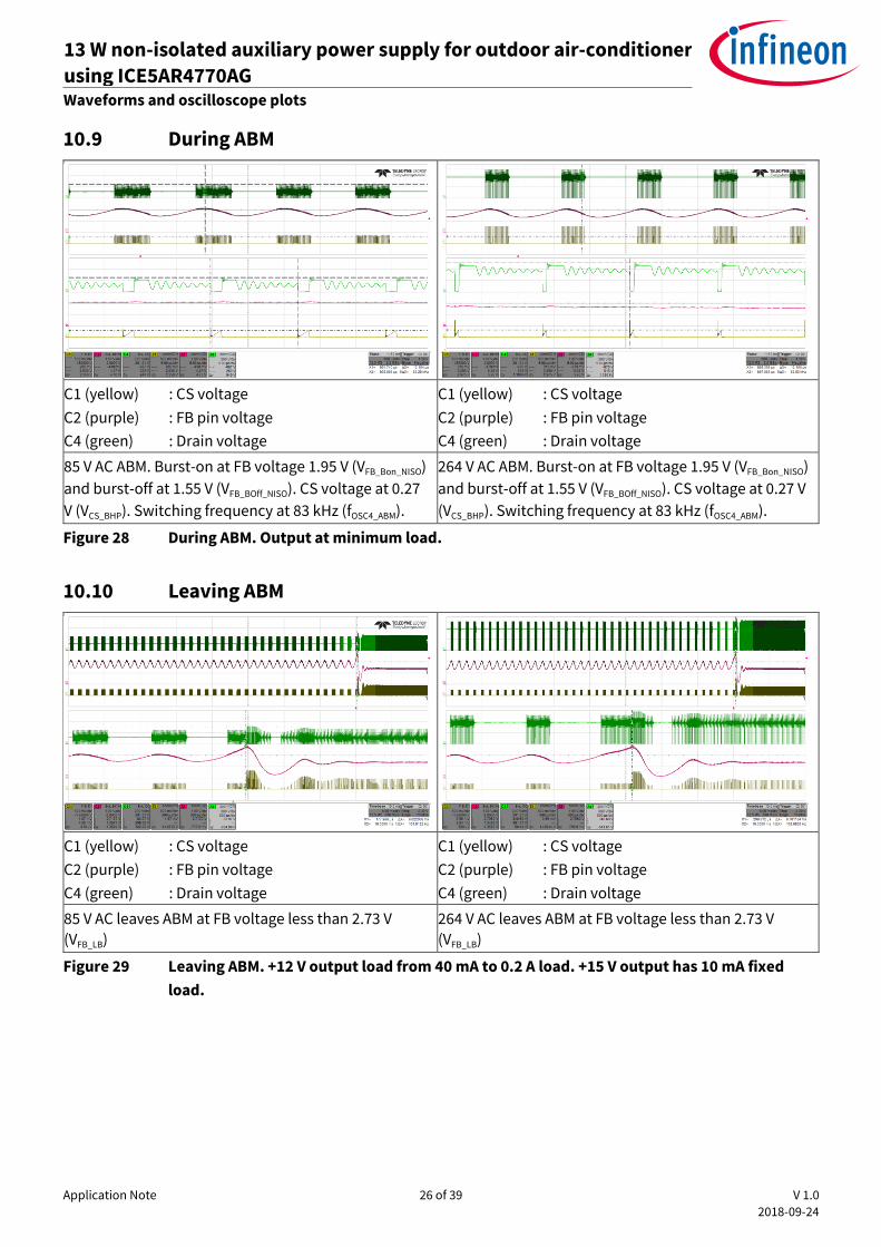
10.9 During ABM ............................................................................................................................................ 26
10.10 Leaving ABM .......................................................................................................................................... 26
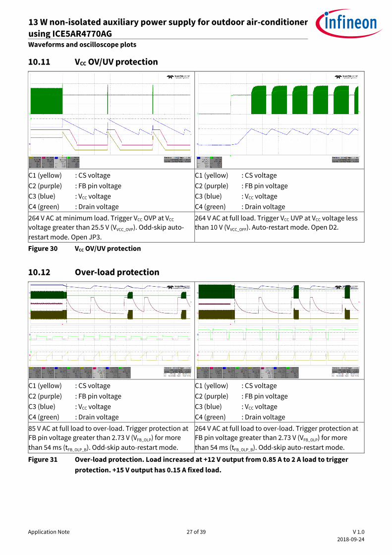
10.11 VCC OV/UV protection ............................................................................................................................. 27
10.12 Over-load protection ............................................................................................................................. 27 10.13 Brown-in and LOVP ............................................................................................................................... 28
11 Appendix A: Transformer design and spreadsheet [3] ................................................................ 29
12 References ........................................................................................................................... 37
Revision history............................................................................................................................. 38
Application Note 3 of 39 V 1.0
2018-09-24
13 W non-isolated auxiliary power supply for outdoor air-conditioner
using ICE5AR4770AG REF_5AR4770AG_13W1 System introduction
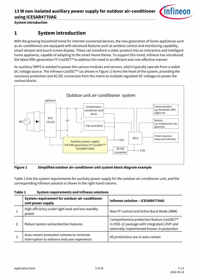
1 System introduction
With the growing household trend for internet-connected devices, the new generation of home appliances such
as air-conditioners are equipped with advanced features such as wireless control and monitoring capability, smart sensors and touch screen display. These can transform a static product into an interactive and intelligent home appliance, capable of adapting to the smart-home theme. To support this trend, Infineon has introduced the latest fifth-generation FF CoolSET™ to address this need in an efficient and cost-effective manner.
An auxiliary SMPS is needed to power the various modules and sensors, which typically operate from a stable DC voltage source. The Infineon CoolSET™ (as shown in Figure 1) forms the heart of the system, providing the
necessary protection and AC/DC conversion from the mains to multiple regulated DC voltages to power the various blocks.
AC
Communicatione.g. Bluetooth, WiFi, Zigbee etc.
Sensors e.g. temperature, fan speed etc.
Timers, buzzers, relays and switches
Outdoor unit air-conditioner system
3.3V
PFC circuit
Auxiliary power supply IFX fifth generation FF CoolSETTM
ICE5AR4770AG
12VMCU
DC/DC converter
Fan and drive
optional
Compressor, condenser and
drive
Figure 1 Simplified outdoor air-conditioner unit system block diagram example
Table 1 lists the system requirements for auxiliary power supply for the outdoor air-conditioner unit, and the corresponding Infineon solution is shown in the right-hand column.
Table 1 System requirements and Infineon solutions
System requirement for outdoor air-conditioner
unit power supply Infineon solution – ICE5AR4770AG
1 High efficiency under light load and low standby
power New FF control and Active Burst Mode (ABM)
2 Robust system and protection features Comprehensive protection feature CoolSET™
in DSO-12 package with integrated LOVP and
externally implemented brown-in protection
3 Auto-restart protection scheme to minimize interruption to enhance end-user experience
All protections are in auto-restart
Application Note 4 of 39 V 1.0
2018-09-24
13 W non-isolated auxiliary power supply for outdoor air-conditioner
using ICE5AR4770AG REF_5AR4770AG_13W1 System introduction
1.1 High efficiency under light load and low standby power
During typical air-conditioner operation, the power requirement fluctuates according to various use cases. However, in most cases where room temperature is already stabilized, the indoor and outdoor air-conditioner
units will reside in an idle state, in which the loading towards the auxiliary power supply is low. It is crucial that the auxiliary power supply operates as efficiently as possible, because it will be in this particular state for most of the period. Under light-load conditions, losses incurred with the power switch are usually dominated by the switching operation. The choice of switching scheme and frequency play a crucial role in ensuring high
conversion efficiency.
In this reference design, ICE5AR4770AG was primarily chosen due to its frequency reduction switching scheme.
Compared with a traditional FF flyback, the CoolSETTM reduces its switching frequency from medium to light
load, thereby minimizing switching losses. Therefore, an efficiency of more than 80 percent is achievable under
25 percent loading conditions and nominal input voltages.
1.2 Simplified circuitry with good integration of power and protection
features
To relieve the designer of the complexity of PCB layout and circuit design, CoolSETTM is a highly integrated device with both a controller and a HV MOSFET integrated into a single, space-saving DSO-12 package. These
certainly help the designer to reduce component count as well as simplifying the layout into a single-layer PCB design for ease of manufacturing, using the traditional cost-effective wave-soldering process.
The various protection features of the CoolSET™, such as integrated LOVP and externally implemented brown-
in protection, boosts the reliability of the power supply.
1.3 Auto-restart protection scheme to minimize interruption to enhance
end-user experience
For an outdoor air-conditioner unit, it would be annoying to both the end-user and the manufacturer if the system were to halt and latch after protection. Accessibility of the input AC plug may also be difficult; therefore,
to minimize interruption, the CoolSETTM implements auto-restart mode for all abnormal protections.
Application Note 5 of 39 V 1.0
2018-09-24
13 W non-isolated auxiliary power supply for outdoor air-conditioner
using ICE5AR4770AG REF_5AR4770AG_13W1 Reference board design
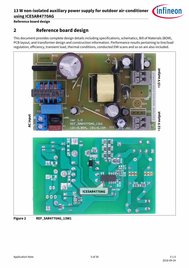
2 Reference board design
This document provides complete design details including specifications, schematics, Bill of Materials (BOM), PCB layout, and transformer design and construction information. Performance results pertaining to line/load regulation, efficiency, transient load, thermal conditions, conducted EMI scans and so on are also included.
Figure 2 REF_5AR4770AG_13W1
ICE5AR4770AG
AC
inp
ut
+1
2 V
ou
tpu
t +
15
V o
utp
ut
Application Note 6 of 39 V 1.0
2018-09-24
13 W non-isolated auxiliary power supply for outdoor air-conditioner
using ICE5AR4770AG REF_5AR4770AG_13W1 Power supply specifications
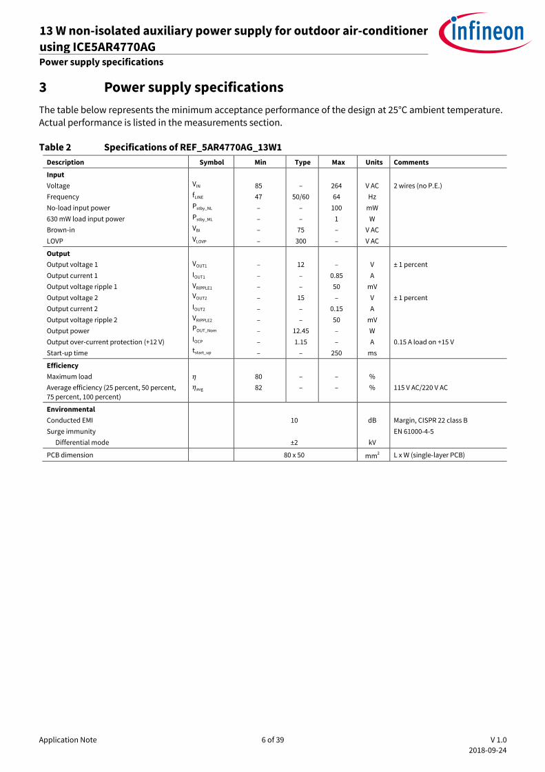
3 Power supply specifications
The table below represents the minimum acceptance performance of the design at 25°C ambient temperature. Actual performance is listed in the measurements section.
Table 2 Specifications of REF_5AR4770AG_13W1
Description Symbol Min Type Max Units Comments
Input
Voltage
Frequency
No-load input power
630 mW load input power
Brown-in
LOVP
VIN
fLINE
Pstby_NL
Pstby_ML
VBI
VLOVP
85
47
–
–
–
–
–
50/60
–
–
75
300
264
64
100
1
–
–
V AC
Hz
mW
W
V AC
V AC
2 wires (no P.E.)
Output
Output voltage 1
Output current 1
Output voltage ripple 1
Output voltage 2
Output current 2
Output voltage ripple 2
Output power
Output over-current protection (+12 V)
Start-up time
VOUT1
IOUT1
VRIPPLE1
VOUT2
IOUT2
VRIPPLE2
POUT_Nom
IOCP
tstart_up
–
–
–
–
–
–
–
–
–
12
–
–
15
–
–
12.45
1.15
–
–
0.85
50
–
0.15
50
–
–
250
V
A
mV
V
A
mV
W
A
ms
± 1 percent
± 1 percent
0.15 A load on +15 V
Efficiency
Maximum load
Average efficiency (25 percent, 50 percent,
75 percent, 100 percent)
𝜂
𝜂avg
80
82
–
–
–
–
%
%
115 V AC/220 V AC
Environmental
Conducted EMI
Surge immunity
Differential mode
10
±2
dB
kV
Margin, CISPR 22 class B
EN 61000-4-5
PCB dimension 80 x 50 mm2 L x W (single-layer PCB)
Application Note 7 of 39 V 1.0
2018-09-24
13 W non-isolated auxiliary power supply for outdoor air-conditioner
using ICE5AR4770AG REF_5AR4770AG_13W1 Circuit diagram
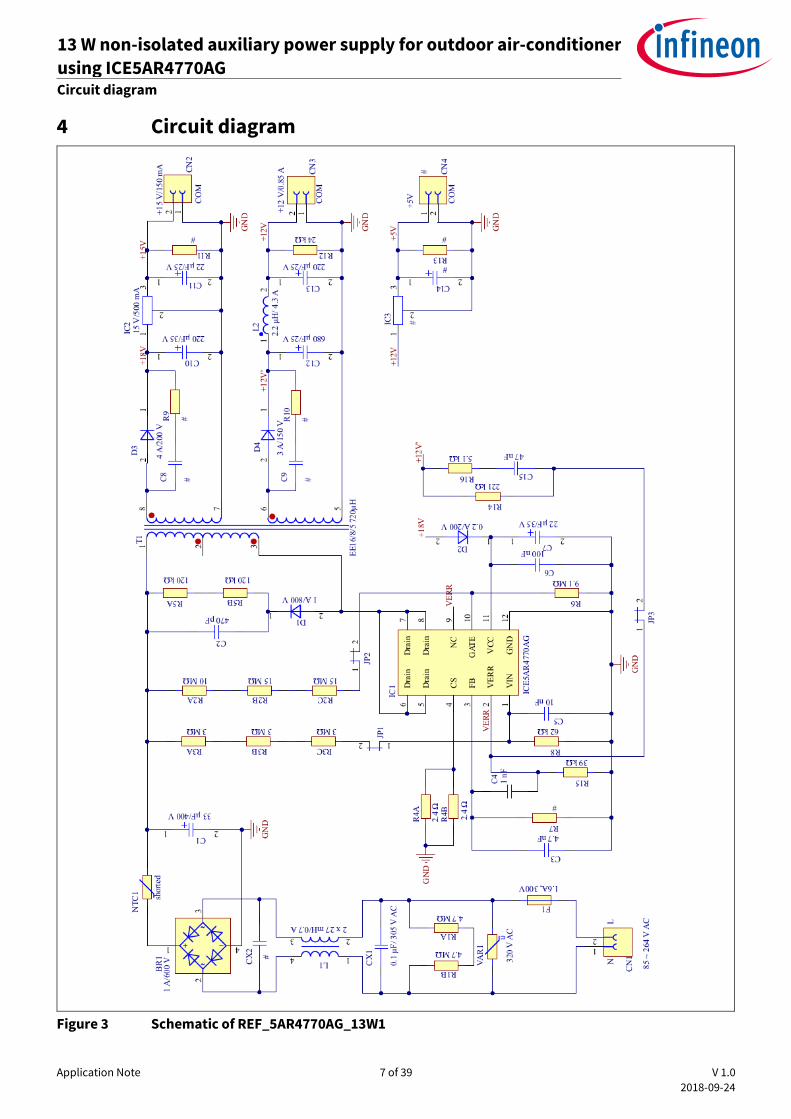
4 Circuit diagram
Figure 3 Schematic of REF_5AR4770AG_13W1
Application Note 8 of 39 V 1.0
2018-09-24
13 W non-isolated auxiliary power supply for outdoor air-conditioner
using ICE5AR4770AG REF_5AR4770AG_13W1 Circuit description
5 Circuit description
In this section, the design circuit for the SMPS unit will be briefly described by the different functional blocks. For details of the design procedure and component selection for the flyback circuitry please refer to the IC design guide [2] and calculation tool [3].
5.1 EMI filtering and line rectification
The input of the power supply unit is taken from the AC power grid which is in the range of 85 V AC ~ 264 V AC. The fuse F1 is directly connected to the input line to protect the system in case of excess current entering the system circuit due to any fault. Following is the varistor VAR1, which is connected across the input to absorb
excessive energy during line-surge transient. The X-capacitor CX1 and Common Mode Choke (CMC) L1 reduce
the EMI noise. R1A and R1B serve as the X-capacitor discharge resistor. The bridge rectifier BR1 rectifies the AC
input into DC voltage, filtered by the bulk capacitor C1.
5.2 Flyback converter power stage
The flyback converter power stage consists of transformer T1, CoolSET™, secondary rectification diodes D3 and D4, secondary output capacitors C10 and C12 and output filter inductor L2.
When the primary HV MOSFET turns on, energy is stored in the transformer. When it turns off, the stored energy is discharged to the output capacitors and into the output load.
Secondary winding is sandwiched between two layers of primary winding to reduce leakage inductance. This
improves efficiency and reduces voltage spikes. An addition of shield winding between the first layer of primary winding and secondary winding helps reduce EMI noise.
For the output rectification, lower forward voltage and ultra-fast recovery diodes can improve efficiency. Capacitor C12 stores the energy needed during output load jumps. LC filter L2/C13 reduces the high-frequency
ripple voltage.
The +15 V output is from the 15 V Low Drop-Out (LDO) regulator (IC2) with an input of +18 V. As such, this output should not be affected by cross-regulation. However, its input should be maintained within the operating range of the LDO.
5.3 Control of flyback converter through fifth-generation FF CoolSET™
ICE5AR4770AG
5.3.1 Current sensing
The ICE5AR4770AG is a current mode controller. The primary peak current is controlled cycle-by-cycle through the CS resistors R4A and R4B in the CS pin (pin 4). Transformer saturation can be avoided through Peak Current Limitation (PCL); therefore, the system is more protected and reliable.
5.3.2 Feedback and compensation network
+12 V output is sensed by resistor/dividers R14 and R15 connected to the VERR pin (pin 2), which is the negative input of the integrated error amplifier of the ICE5AR4770AG. A feed-forward compensation network (C15 and
R16) and capacitors C3 and C4 are added for feedback loop stability.
The FB pin of ICE5AR4770AG is a multi-function pin, which is used to select the entry/exit burst power level
through the resistor at the FB pin (R7) and also the burst-on/burst-off sense input during ABM.
Application Note 9 of 39 V 1.0
2018-09-24
13 W non-isolated auxiliary power supply for outdoor air-conditioner
using ICE5AR4770AG REF_5AR4770AG_13W1 Circuit description
5.4 Unique features of the fifth-generation FF CoolSET™ ICE5AR4770AG
5.4.1 Fast self-start-up and sustaining of VCC
The IC uses a cascode structure to fast-charge the VCC capacitor. Pull-up resistors R2A, R2B and R2C connected to the GATE pin (pin 10) are used to initiate the start-up phase. At first, 0.2 mA is used to charge the VCC capacitor from 0 V to 1.1 V. This is a protection which reduces the power dissipation of the power MOSFET
during VCC short-to-GND condition. Thereafter, a much higher charging current of 3.2 mA will charge the VCC
capacitor until the VCC_ON is reached. Start-up time of less than 250 ms is achievable with a VCC capacitor of 22 µF.
After start-up, the IC VCC supply is usually sustained by the auxiliary winding of the transformer, which needs to
support the VCC to be above Under Voltage Lockout (UVLO) voltage (10 V typ.). In this reference board, the VCC supply is tapped from the +18 V winding.
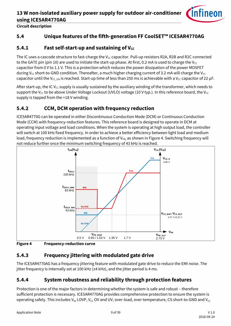
5.4.2 CCM, DCM operation with frequency reduction
ICE5AR4770G can be operated in either Discontinuous Conduction Mode (DCM) or Continuous Conduction
Mode (CCM) with frequency-reduction features. This reference board is designed to operate in DCM at operating input voltage and load conditions. When the system is operating at high output load, the controller will switch at 100 kHz fixed frequency. In order to achieve a better efficiency between light load and medium
load, frequency reduction is implemented as a function of VFB, as shown in Figure 4. Switching frequency will
not reduce further once the minimum switching frequency of 43 kHz is reached.
VFB
fSW(VFB)
1.35 V
1.7 V
VFB_OLP
2.73 V
fOSC4_MIN
43 kHz
fOSC4
100 kHz
VCS (VFB)
VCS_N
0.80 V
VFB_EBxP
0.93 / 1.03 V
VCS_BHP / VCS_BLP
0.27 V /0.22 V
fOSC4_ABM
83 kHz
BM
0.5 V
No BM
BM
No BM
Fsw
Vcs
Figure 4 Frequency-reduction curve
5.4.3 Frequency jittering with modulated gate drive
The ICE5AR4770AG has a frequency jittering feature with modulated gate drive to reduce the EMI noise. The
jitter frequency is internally set at 100 kHz (±4 kHz), and the jitter period is 4 ms.
5.4.4 System robustness and reliability through protection features
Protection is one of the major factors in determining whether the system is safe and robust – therefore
sufficient protection is necessary. ICE5AR4770AG provides comprehensive protection to ensure the system is
operating safely. This includes VIN LOVP, VCC OV and UV, over-load, over-temperature, CS short-to-GND and VCC
Application Note 10 of 39 V 1.0
2018-09-24
13 W non-isolated auxiliary power supply for outdoor air-conditioner
using ICE5AR4770AG REF_5AR4770AG_13W1 Circuit description
short-to-GND. When those faults are found, the system will enter into protection mode. Once the fault is removed, the system resumes normal operation. A list of protections and the failure conditions is shown in the
table below.
Table 3 Protection functions of ICE5AR4770AG
Protection function Failure condition Protection mode VCC OV VVCC greater than 25.5 V Odd-skip auto-restart
VCC UV VVCC less than 10 V Auto-restart
VIN LOVP VVIN greater than 2.85 V Non-switch auto-restart
Over-load VFB greater than 2.73 V and lasts for
54 ms
Odd-skip auto-restart
Over-temperature TJ greater than 140°C (40°C
hysteresis)
Non-switch auto-restart
CS short-to-GND VCS less than 0.1 V, lasts for 0.4 µs
and three consecutive pulses Odd-skip auto-restart
VCC short-to-GND
(VVCC = 0 V, start-up = 50 MΩ and VDRAIN = 90 V)
VVCC less than 1.1 V, IVCC_Charge1 ≈ -0.2
mA
Cannot start up
5.5 Clamper circuit
A clamper network consisting of D1, C2, R5A and R5B is used to reduce the switching voltage spikes across the
DRAIN of the integrated HV MOSFET of the CoolSET™, which are generated by the leakage inductance of the
transformer T1. This is a dissipative circuit; therefore, R5A, R5B and C2 need to be fine-tuned depending on the
voltage derating factor and efficiency requirement.
5.6 PCB design tips
For a good PCB design layout, there are several points to note.
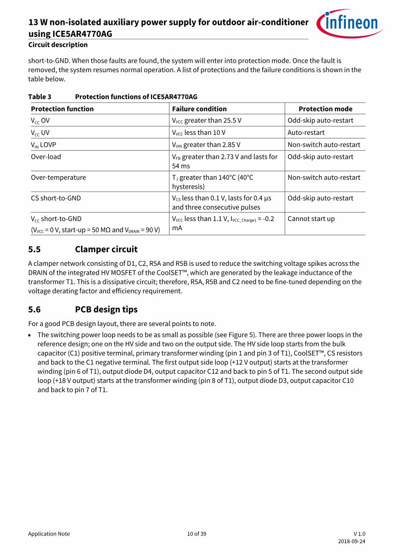
The switching power loop needs to be as small as possible (see Figure 5). There are three power loops in the
reference design; one on the HV side and two on the output side. The HV side loop starts from the bulk
capacitor (C1) positive terminal, primary transformer winding (pin 1 and pin 3 of T1), CoolSET™, CS resistors and back to the C1 negative terminal. The first output side loop (+12 V output) starts at the transformer
winding (pin 6 of T1), output diode D4, output capacitor C12 and back to pin 5 of T1. The second output side loop (+18 V output) starts at the transformer winding (pin 8 of T1), output diode D3, output capacitor C10
and back to pin 7 of T1.
Application Note 11 of 39 V 1.0
2018-09-24
13 W non-isolated auxiliary power supply for outdoor air-conditioner
using ICE5AR4770AG REF_5AR4770AG_13W1 Circuit description
Figure 5 PCB layout tips
Star-ground connection should be used to reduce High Frequency (HF) noise coupling that can affect the
functional operation. The ground of the small-signal components, e.g. R6, R7, R8, R15, C3, C5 and C6, should
connect directly to the IC ground (pin 12 of IC1).
Separating the HV components and LV components, e.g. clamper circuit D1, C2, R5A and R5B, at the top part
of the PCB and the other LV components at the lower part of the PCB can reduce the spark-over chance of
the high energy surge during a lightning surge test.
Make the PCB copper pour on the DRAIN pin of the MOSFET cover as wide an area as possible to act as a
heatsink.
5.7 EMI reduction tips
EMI compliance is always a challenge for the power supply designer. There are several critical points to consider in order to achieve a satisfactory EMI performance.
A proper transformer design can significantly reduce EMI. Low leakage inductance can incur a low switching spike and HF noise. Interlaced winding technique is the most common practice to reduce leakage inductance. Winding shield, core shield and whole transformer shield are also some of the techniques used
to reduce EMI.
Input CMC and X-capacitor greatly reduce EMI, but this is costly and impractical especially for low-power applications.
Short-switching power-loop design in the PCB (as described in section 5.6) can reduce radiated EMI due to the antenna effect.
An output diode snubber circuit (R9, R10, C8 and C9) can reduce HF noise.
Ferrite beads can reduce HF noise, especially on critical nodes such as the DRAIN pin, clamper diode and
output diode terminals. There is no ferrite bead used in this design, as this can reduce the efficiency due to additional losses especially on high-current terminals.
Application Note 12 of 39 V 1.0
2018-09-24
13 W non-isolated auxiliary power supply for outdoor air-conditioner
using ICE5AR4770AG REF_5AR4770AG_13W1 PCB layout
6 PCB layout
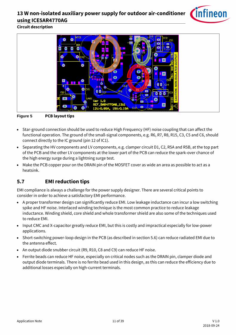
6.1 Top side
Figure 6 Top side component legend
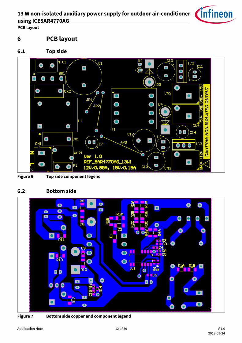
6.2 Bottom side
Figure 7 Bottom side copper and component legend
Application Note 13 of 39 V 1.0
2018-09-24
13 W non-isolated auxiliary power supply for outdoor air-conditioner
using ICE5AR4770AG REF_5AR4770AG_13W1 BOM
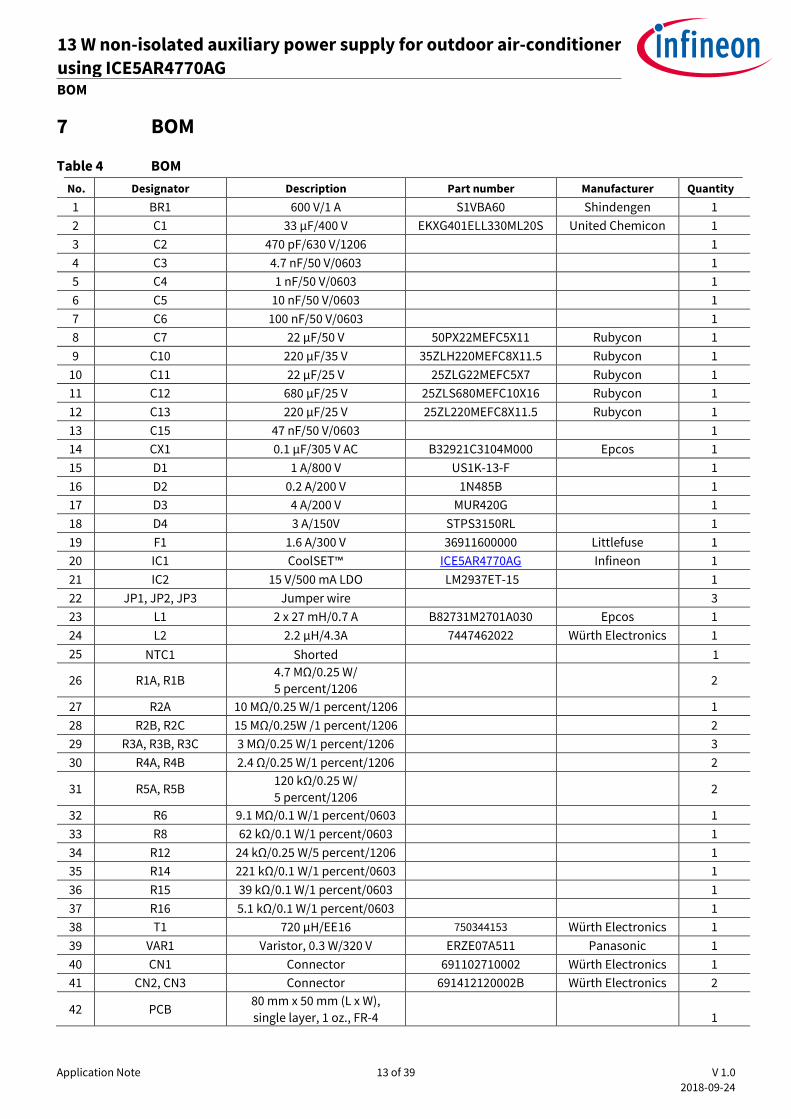
7 BOM
Table 4 BOM
No. Designator Description Part number Manufacturer Quantity
1 BR1 600 V/1 A S1VBA60 Shindengen 1
2 C1 33 µF/400 V EKXG401ELL330ML20S United Chemicon 1
3 C2 470 pF/630 V/1206 1
4 C3 4.7 nF/50 V/0603 1
5 C4 1 nF/50 V/0603 1
6 C5 10 nF/50 V/0603 1
7 C6 100 nF/50 V/0603 1
8 C7 22 µF/50 V 50PX22MEFC5X11 Rubycon 1
9 C10 220 µF/35 V 35ZLH220MEFC8X11.5 Rubycon 1
10 C11 22 µF/25 V 25ZLG22MEFC5X7 Rubycon 1
11 C12 680 µF/25 V 25ZLS680MEFC10X16 Rubycon 1
12 C13 220 µF/25 V 25ZL220MEFC8X11.5 Rubycon 1
13 C15 47 nF/50 V/0603 1
14 CX1 0.1 µF/305 V AC B32921C3104M000 Epcos 1
15 D1 1 A/800 V US1K-13-F 1
16 D2 0.2 A/200 V 1N485B 1
17 D3 4 A/200 V MUR420G 1
18 D4 3 A/150V STPS3150RL 1
19 F1 1.6 A/300 V 36911600000 Littlefuse 1
20 IC1 CoolSET™ ICE5AR4770AG Infineon 1
21 IC2 15 V/500 mA LDO LM2937ET-15 1
22 JP1, JP2, JP3 Jumper wire 3
23 L1 2 x 27 mH/0.7 A B82731M2701A030 Epcos 1
24 L2 2.2 µH/4.3A 7447462022 Würth Electronics 1
25 NTC1 Shorted 1
26 R1A, R1B 4.7 MΩ/0.25 W/
5 percent/1206 2
27 R2A 10 MΩ/0.25 W/1 percent/1206 1
28 R2B, R2C 15 MΩ/0.25W /1 percent/1206 2
29 R3A, R3B, R3C 3 MΩ/0.25 W/1 percent/1206 3
30 R4A, R4B 2.4 Ω/0.25 W/1 percent/1206 2
31 R5A, R5B 120 kΩ/0.25 W/
5 percent/1206 2
32 R6 9.1 MΩ/0.1 W/1 percent/0603 1
33 R8 62 kΩ/0.1 W/1 percent/0603 1
34 R12 24 kΩ/0.25 W/5 percent/1206 1
35 R14 221 kΩ/0.1 W/1 percent/0603 1
36 R15 39 kΩ/0.1 W/1 percent/0603 1
37 R16 5.1 kΩ/0.1 W/1 percent/0603 1
38 T1 720 µH/EE16 750344153 Würth Electronics 1
39 VAR1 Varistor, 0.3 W/320 V ERZE07A511 Panasonic 1
40 CN1 Connector 691102710002 Würth Electronics 1
41 CN2, CN3 Connector 691412120002B Würth Electronics 2
42 PCB 80 mm x 50 mm (L x W),
single layer, 1 oz., FR-4 1
Application Note 14 of 39 V 1.0
2018-09-24
13 W non-isolated auxiliary power supply for outdoor air-conditioner
using ICE5AR4770AG REF_5AR4770AG_13W1 Transformer specification
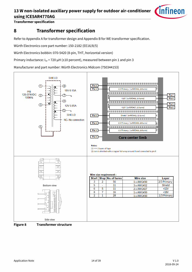
8 Transformer specification
Refer to Appendix A for transformer design and Appendix B for WE transformer specification.
Würth Electronics core part number: 150-2182 (EE16/8/5)
Würth Electronics bobbin: 070-5420 (8-pin, THT, horizontal version)
Primary inductance: LP = 720 μH (±10 percent), measured between pin 1 and pin 3
Manufacturer and part number: Würth Electronics Midcom (750344153)
Bottom view
Side view
Figure 8 Transformer structure
Application Note 15 of 39 V 1.0
2018-09-24
13 W non-isolated auxiliary power supply for outdoor air-conditioner
using ICE5AR4770AG REF_5AR4770AG_13W1 Measurement data and graphs
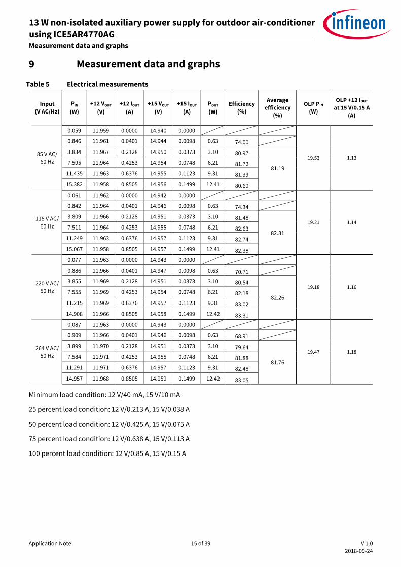
9 Measurement data and graphs
Table 5 Electrical measurements
Input
(V AC/Hz)
PIN
(W)
+12 VOUT
(V)
+12 IOUT
(A)
+15 VOUT
(V)
+15 IOUT
(A)
POUT
(W)
Efficiency
(%)
Average
efficiency
(%)
OLP PIN
(W)
OLP +12 IOUT
at 15 V/0.15 A
(A)
85 V AC/
60 Hz
0.059 11.959 0.0000 14.940 0.0000
19.53 1.13
0.846 11.961 0.0401 14.944 0.0098 0.63 74.00
3.834 11.967 0.2128 14.950 0.0373 3.10 80.97
81.19 7.595 11.964 0.4253 14.954 0.0748 6.21 81.72
11.435 11.963 0.6376 14.955 0.1123 9.31 81.39
15.382 11.958 0.8505 14.956 0.1499 12.41 80.69
115 V AC/
60 Hz
0.061 11.962 0.0000 14.942 0.0000
19.21 1.14
0.842 11.964 0.0401 14.946 0.0098 0.63 74.34
3.809 11.966 0.2128 14.951 0.0373 3.10 81.48
82.31 7.511 11.964 0.4253 14.955 0.0748 6.21 82.63
11.249 11.963 0.6376 14.957 0.1123 9.31 82.74
15.067 11.958 0.8505 14.957 0.1499 12.41 82.38
220 V AC/
50 Hz
0.077 11.963 0.0000 14.943 0.0000
19.18 1.16
0.886 11.966 0.0401 14.947 0.0098 0.63 70.71
3.855 11.969 0.2128 14.951 0.0373 3.10 80.54
82.26 7.555 11.969 0.4253 14.954 0.0748 6.21 82.18
11.215 11.969 0.6376 14.957 0.1123 9.31 83.02
14.908 11.966 0.8505 14.958 0.1499 12.42 83.31
264 V AC/
50 Hz
0.087 11.963 0.0000 14.943 0.0000
19.47 1.18
0.909 11.966 0.0401 14.946 0.0098 0.63 68.91
3.899 11.970 0.2128 14.951 0.0373 3.10 79.64
81.76 7.584 11.971 0.4253 14.955 0.0748 6.21 81.88
11.291 11.971 0.6376 14.957 0.1123 9.31 82.48
14.957 11.968 0.8505 14.959 0.1499 12.42 83.05
Minimum load condition: 12 V/40 mA, 15 V/10 mA
25 percent load condition: 12 V/0.213 A, 15 V/0.038 A
50 percent load condition: 12 V/0.425 A, 15 V/0.075 A
75 percent load condition: 12 V/0.638 A, 15 V/0.113 A
100 percent load condition: 12 V/0.85 A, 15 V/0.15 A
Application Note 16 of 39 V 1.0
2018-09-24
13 W non-isolated auxiliary power supply for outdoor air-conditioner
using ICE5AR4770AG REF_5AR4770AG_13W1 Measurement data and graphs
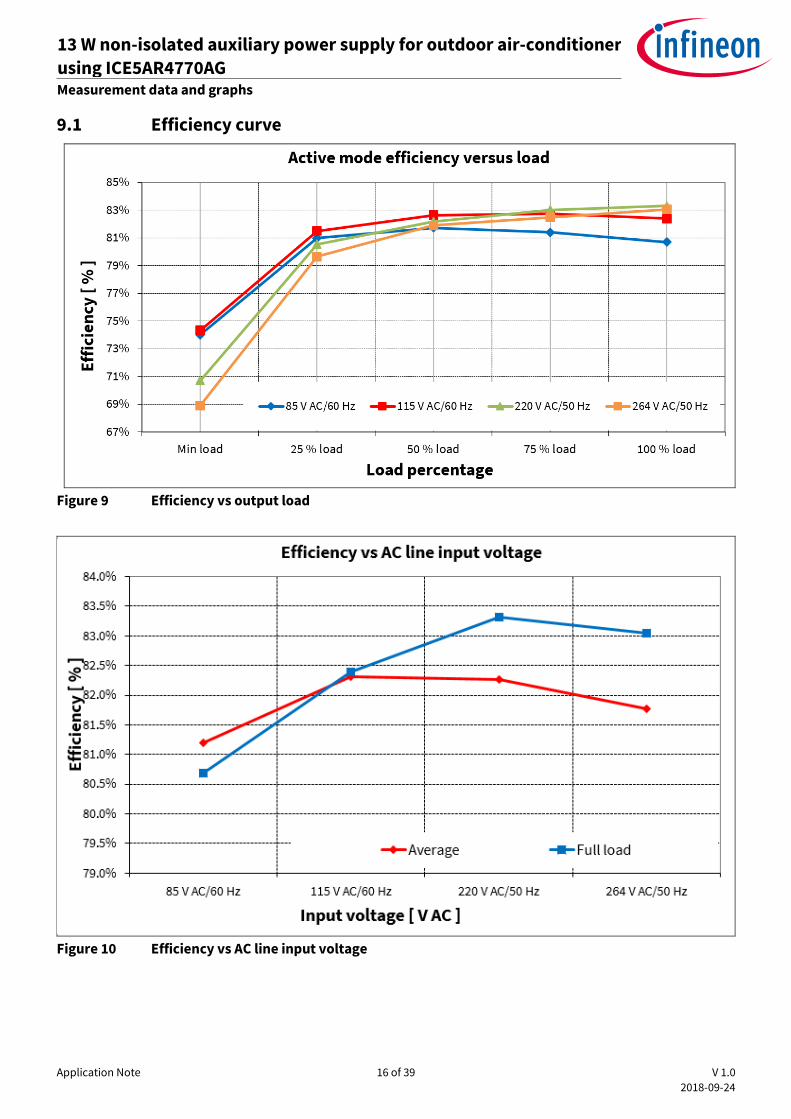
9.1 Efficiency curve
Figure 9 Efficiency vs output load
Figure 10 Efficiency vs AC line input voltage
Application Note 17 of 39 V 1.0
2018-09-24
13 W non-isolated auxiliary power supply for outdoor air-conditioner
using ICE5AR4770AG REF_5AR4770AG_13W1 Measurement data and graphs
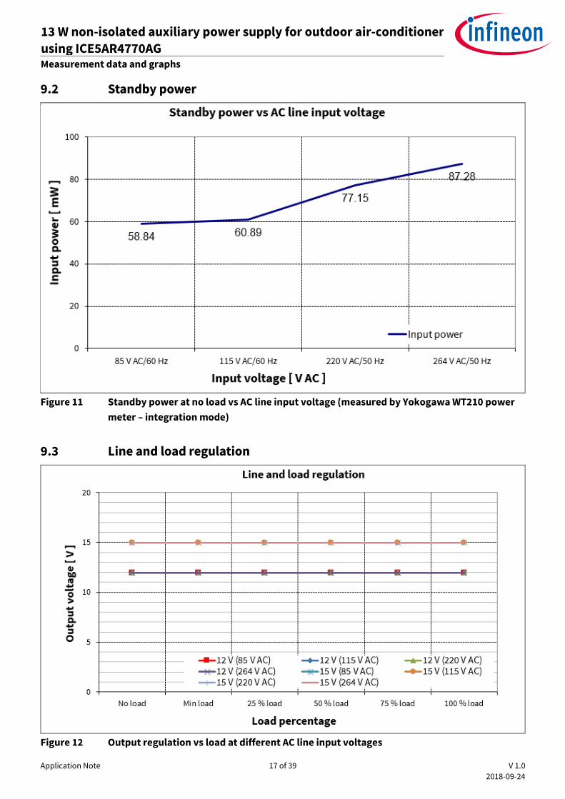
9.2 Standby power
Figure 11 Standby power at no load vs AC line input voltage (measured by Yokogawa WT210 power
meter – integration mode)
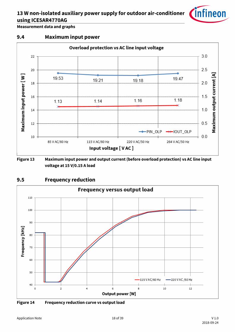
9.3 Line and load regulation
Figure 12 Output regulation vs load at different AC line input voltages
Application Note 18 of 39 V 1.0
2018-09-24
13 W non-isolated auxiliary power supply for outdoor air-conditioner
using ICE5AR4770AG REF_5AR4770AG_13W1 Measurement data and graphs
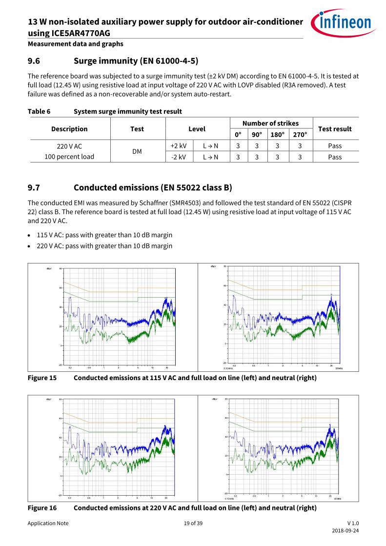
9.4 Maximum input power
Figure 13 Maximum input power and output current (before overload protection) vs AC line input
voltage at 15 V/0.15 A load
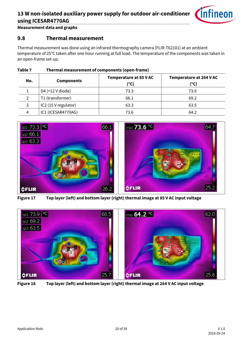
9.5 Frequency reduction
Figure 14 Frequency reduction curve vs output load
Application Note 19 of 39 V 1.0
2018-09-24
13 W non-isolated auxiliary power supply for outdoor air-conditioner
using ICE5AR4770AG REF_5AR4770AG_13W1 Measurement data and graphs
9.6 Surge immunity (EN 61000-4-5)
The reference board was subjected to a surge immunity test (±2 kV DM) according to EN 61000-4-5. It is tested at full load (12.45 W) using resistive load at input voltage of 220 V AC with LOVP disabled (R3A removed). A test
failure was defined as a non-recoverable and/or system auto-restart.
Table 6 System surge immunity test result
Description Test Level Number of strikes
Test result 0° 90° 180° 270°
220 V AC
100 percent load DM
+2 kV L → N 3 3 3 3 Pass
-2 kV L → N 3 3 3 3 Pass
9.7 Conducted emissions (EN 55022 class B)
The conducted EMI was measured by Schaffner (SMR4503) and followed the test standard of EN 55022 (CISPR 22) class B. The reference board is tested at full load (12.45 W) using resistive load at input voltage of 115 V AC
and 220 V AC.
115 V AC: pass with greater than 10 dB margin
220 V AC: pass with greater than 10 dB margin
Figure 15 Conducted emissions at 115 V AC and full load on line (left) and neutral (right)
Figure 16 Conducted emissions at 220 V AC and full load on line (left) and neutral (right)
Application Note 20 of 39 V 1.0
2018-09-24
13 W non-isolated auxiliary power supply for outdoor air-conditioner
using ICE5AR4770AG REF_5AR4770AG_13W1 Measurement data and graphs
9.8 Thermal measurement
Thermal measurement was done using an infrared thermography camera (FLIR-T62101) at an ambient temperature of 25°C taken after one hour running at full load. The temperature of the components was taken in
an open-frame set-up.
Table 7 Thermal measurement of components (open-frame)
No. Components Temperature at 85 V AC
(°C)
Temperature at 264 V AC
(°C)
1 D4 (+12 V diode) 73.3 73.9
2 T1 (transformer) 66.1 69.2
3 IC2 (15 V regulator) 63.3 63.5
4 IC1 (ICE5AR4770AG) 73.6 64.2
Figure 17 Top layer (left) and bottom layer (right) thermal image at 85 V AC input voltage
Figure 18 Top layer (left) and bottom layer (right) thermal image at 264 V AC input voltage
Application Note 21 of 39 V 1.0
2018-09-24
13 W non-isolated auxiliary power supply for outdoor air-conditioner
using ICE5AR4770AG REF_5AR4770AG_13W1 Measurement data and graphs
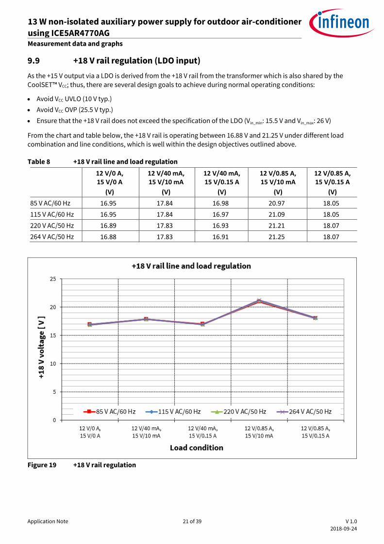
9.9 +18 V rail regulation (LDO input)
As the +15 V output via a LDO is derived from the +18 V rail from the transformer which is also shared by the CoolSET™ VCC; thus, there are several design goals to achieve during normal operating conditions:
Avoid VCC UVLO (10 V typ.)
Avoid VCC OVP (25.5 V typ.)
Ensure that the +18 V rail does not exceed the specification of the LDO (Vin_min: 15.5 V and Vin_max: 26 V)
From the chart and table below, the +18 V rail is operating between 16.88 V and 21.25 V under different load combination and line conditions, which is well within the design objectives outlined above.
Table 8 +18 V rail line and load regulation
12 V/0 A, 15 V/0 A
(V)
12 V/40 mA, 15 V/10 mA
(V)
12 V/40 mA, 15 V/0.15 A
(V)
12 V/0.85 A, 15 V/10 mA
(V)
12 V/0.85 A, 15 V/0.15 A
(V)
85 V AC/60 Hz 16.95 17.84 16.98 20.97 18.05
115 V AC/60 Hz 16.95 17.84 16.97 21.09 18.05
220 V AC/50 Hz 16.89 17.83 16.93 21.21 18.07
264 V AC/50 Hz 16.88 17.83 16.91 21.25 18.07
Figure 19 +18 V rail regulation
Application Note 22 of 39 V 1.0
2018-09-24
13 W non-isolated auxiliary power supply for outdoor air-conditioner
using ICE5AR4770AG REF_5AR4770AG_13W1 Waveforms and oscilloscope plots
10 Waveforms and oscilloscope plots
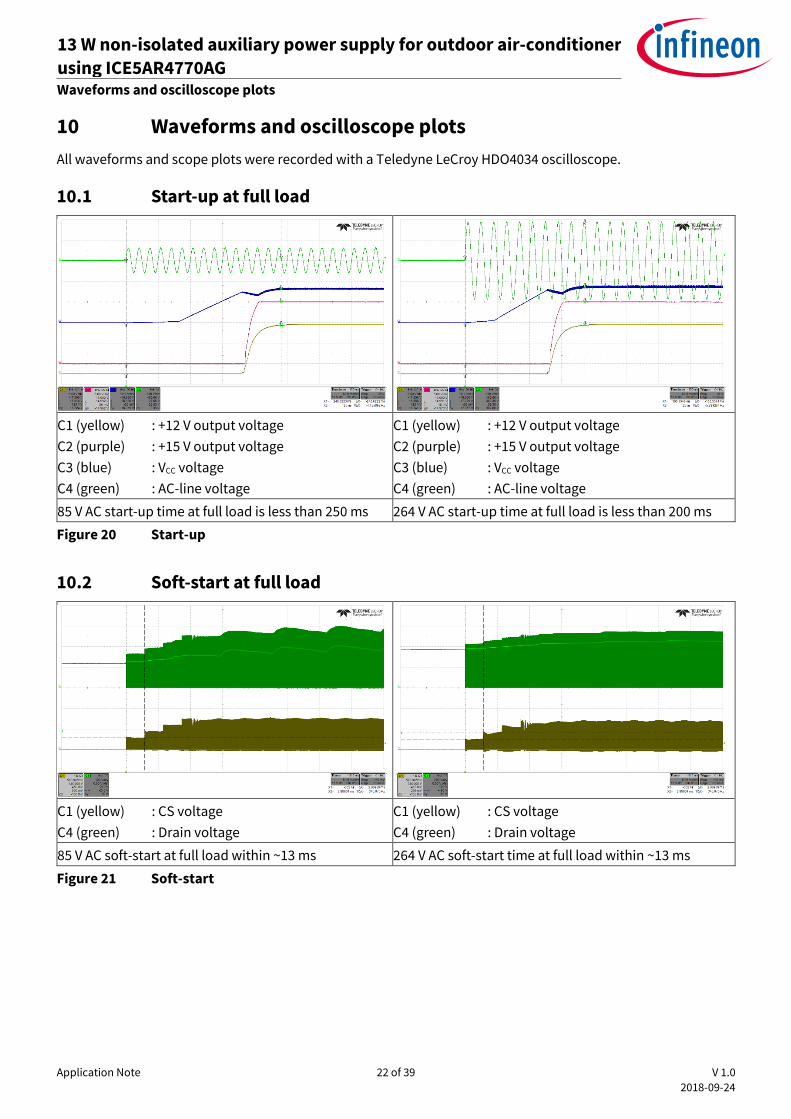
All waveforms and scope plots were recorded with a Teledyne LeCroy HDO4034 oscilloscope.
10.1 Start-up at full load
C1 (yellow) : +12 V output voltage
C2 (purple) : +15 V output voltage
C3 (blue) : VCC voltage
C4 (green) : AC-line voltage
C1 (yellow) : +12 V output voltage
C2 (purple) : +15 V output voltage
C3 (blue) : VCC voltage
C4 (green) : AC-line voltage
85 V AC start-up time at full load is less than 250 ms 264 V AC start-up time at full load is less than 200 ms
Figure 20 Start-up
10.2 Soft-start at full load
C1 (yellow) : CS voltage
C4 (green) : Drain voltage
C1 (yellow) : CS voltage
C4 (green) : Drain voltage
85 V AC soft-start at full load within ~13 ms 264 V AC soft-start time at full load within ~13 ms
Figure 21 Soft-start

Application Note 23 of 39 V 1.0
2018-09-24
13 W non-isolated auxiliary power supply for outdoor air-conditioner
using ICE5AR4770AG REF_5AR4770AG_13W1 Waveforms and oscilloscope plots
10.3 Drain and CS voltage at full load
C1 (yellow) : CS voltage
C4 (green) : Drain voltage
C1 (yellow) : CS voltage
C4 (green) : Drain voltage
85 V AC maximum drain voltage at full load is ~294 V 264 V AC maximum drain voltage at full load is ~555 V
Figure 22 Drain and CS voltage
10.4 Frequency jittering and modulated gate drive at full load
C1 (yellow) : Gate voltage
F1 (yellow) : Frequency track of gate voltage
C1 (yellow) : Gate voltage
85 V AC frequency jittering at full load is ~96 kHz to
~104 kHz with jitter period of 4 ms
85 V AC modulated gate drive at ~120 ns rise time
Figure 23 Frequency jittering and modulated gate drive
Application Note 24 of 39 V 1.0
2018-09-24
13 W non-isolated auxiliary power supply for outdoor air-conditioner
using ICE5AR4770AG REF_5AR4770AG_13W1 Waveforms and oscilloscope plots
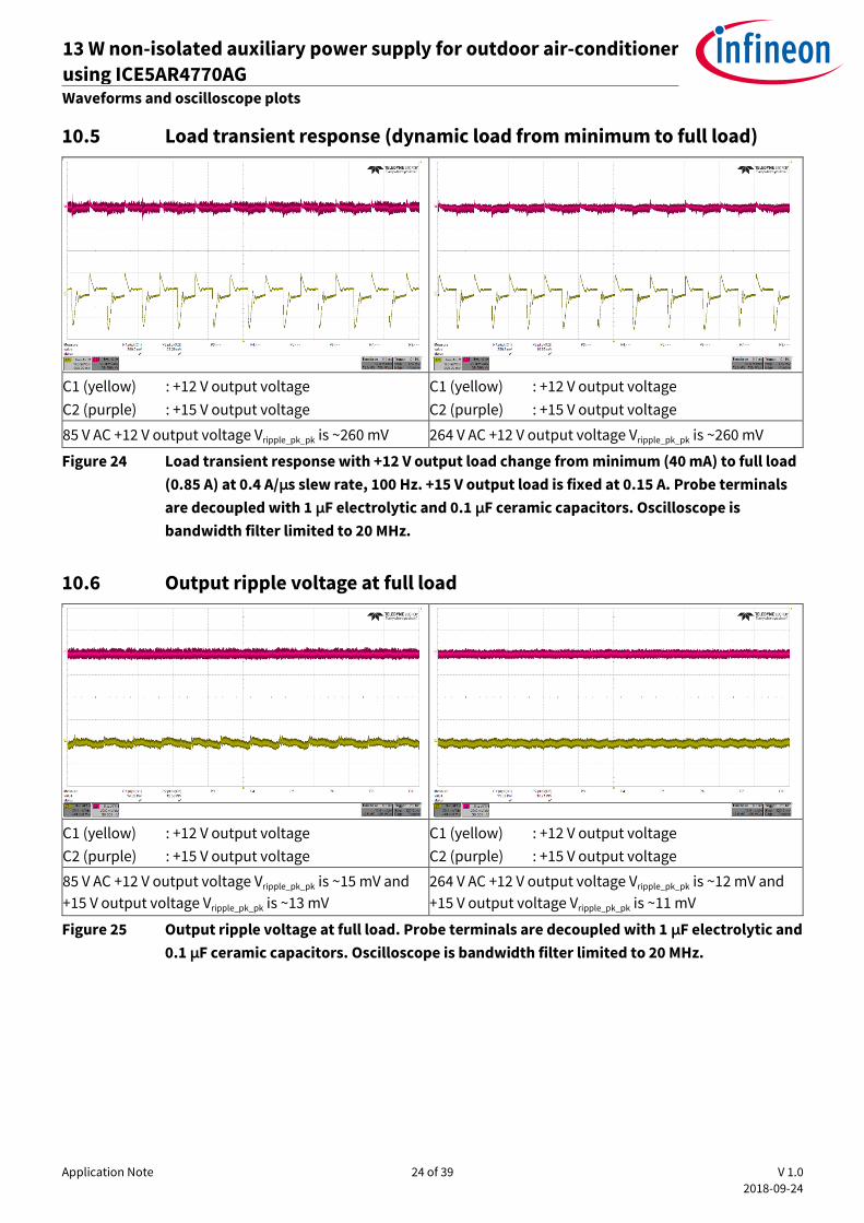
10.5 Load transient response (dynamic load from minimum to full load)
C1 (yellow) : +12 V output voltage
C2 (purple) : +15 V output voltage
C1 (yellow) : +12 V output voltage
C2 (purple) : +15 V output voltage
85 V AC +12 V output voltage Vripple_pk_pk is ~260 mV 264 V AC +12 V output voltage Vripple_pk_pk is ~260 mV
Figure 24 Load transient response with +12 V output load change from minimum (40 mA) to full load
(0.85 A) at 0.4 A/µs slew rate, 100 Hz. +15 V output load is fixed at 0.15 A. Probe terminals
are decoupled with 1 µF electrolytic and 0.1 µF ceramic capacitors. Oscilloscope is
bandwidth filter limited to 20 MHz.
10.6 Output ripple voltage at full load
C1 (yellow) : +12 V output voltage
C2 (purple) : +15 V output voltage
C1 (yellow) : +12 V output voltage
C2 (purple) : +15 V output voltage
85 V AC +12 V output voltage Vripple_pk_pk is ~15 mV and
+15 V output voltage Vripple_pk_pk is ~13 mV
264 V AC +12 V output voltage Vripple_pk_pk is ~12 mV and
+15 V output voltage Vripple_pk_pk is ~11 mV
Figure 25 Output ripple voltage at full load. Probe terminals are decoupled with 1 µF electrolytic and
0.1 µF ceramic capacitors. Oscilloscope is bandwidth filter limited to 20 MHz.
Application Note 25 of 39 V 1.0
2018-09-24
13 W non-isolated auxiliary power supply for outdoor air-conditioner
using ICE5AR4770AG REF_5AR4770AG_13W1 Waveforms and oscilloscope plots
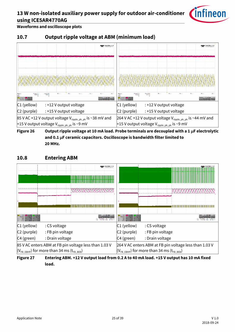
10.7 Output ripple voltage at ABM (minimum load)
C1 (yellow) : +12 V output voltage
C2 (purple) : +15 V output voltage
C1 (yellow) : +12 V output voltage
C2 (purple) : +15 V output voltage
85 V AC +12 V output voltage Vripple_pk_pk is ~38 mV and
+15 V output voltage Vripple_pk_pk is ~9 mV
264 V AC +12 V output voltage Vripple_pk_pk is ~44 mV and
+15 V output voltage Vripple_pk_pk is ~9 mV
Figure 26 Output ripple voltage at 10 mA load. Probe terminals are decoupled with a 1 µF electrolytic
and 0.1 µF ceramic capacitors. Oscilloscope is bandwidth filter limited to
20 MHz.
10.8 Entering ABM
C1 (yellow) : CS voltage
C2 (purple) : FB pin voltage
C4 (green) : Drain voltage
C1 (yellow) : CS voltage
C2 (purple) : FB pin voltage
C4 (green) : Drain voltage
85 V AC enters ABM at FB pin voltage less than 1.03 V
(VFB_EBHP) for more than 34 ms (tFB_BEB)
264 V AC enters ABM at FB pin voltage less than 1.03 V
(VFB_EBHP) for more than 34 ms (tFB_BEB)
Figure 27 Entering ABM. +12 V output load from 0.2 A to 40 mA load. +15 V output has 10 mA fixed
load.
Application Note 26 of 39 V 1.0
2018-09-24
13 W non-isolated auxiliary power supply for outdoor air-conditioner
using ICE5AR4770AG REF_5AR4770AG_13W1 Waveforms and oscilloscope plots
10.9 During ABM
C1 (yellow) : CS voltage
C2 (purple) : FB pin voltage
C4 (green) : Drain voltage
C1 (yellow) : CS voltage
C2 (purple) : FB pin voltage
C4 (green) : Drain voltage
85 V AC ABM. Burst-on at FB voltage 1.95 V (VFB_Bon_NISO)
and burst-off at 1.55 V (VFB_BOff_NISO). CS voltage at 0.27
V (VCS_BHP). Switching frequency at 83 kHz (fOSC4_ABM).
264 V AC ABM. Burst-on at FB voltage 1.95 V (VFB_Bon_NISO)
and burst-off at 1.55 V (VFB_BOff_NISO). CS voltage at 0.27 V
(VCS_BHP). Switching frequency at 83 kHz (fOSC4_ABM).
Figure 28 During ABM. Output at minimum load.
10.10 Leaving ABM
C1 (yellow) : CS voltage
C2 (purple) : FB pin voltage
C4 (green) : Drain voltage
C1 (yellow) : CS voltage
C2 (purple) : FB pin voltage
C4 (green) : Drain voltage
85 V AC leaves ABM at FB voltage less than 2.73 V
(VFB_LB)
264 V AC leaves ABM at FB voltage less than 2.73 V
(VFB_LB)
Figure 29 Leaving ABM. +12 V output load from 40 mA to 0.2 A load. +15 V output has 10 mA fixed
load.
Application Note 27 of 39 V 1.0
2018-09-24
13 W non-isolated auxiliary power supply for outdoor air-conditioner
using ICE5AR4770AG REF_5AR4770AG_13W1 Waveforms and oscilloscope plots
10.11 VCC OV/UV protection
C1 (yellow) : CS voltage
C2 (purple) : FB pin voltage
C3 (blue) : VCC voltage
C4 (green) : Drain voltage
C1 (yellow) : CS voltage
C2 (purple) : FB pin voltage
C3 (blue) : VCC voltage
C4 (green) : Drain voltage
264 V AC at minimum load. Trigger VCC OVP at VCC
voltage greater than 25.5 V (VVCC_OVP). Odd-skip auto-
restart mode. Open JP3.
264 V AC at full load. Trigger VCC UVP at VCC voltage less
than 10 V (VVCC_OFF). Auto-restart mode. Open D2.
Figure 30 VCC OV/UV protection
10.12 Over-load protection
C1 (yellow) : CS voltage
C2 (purple) : FB pin voltage
C3 (blue) : VCC voltage
C4 (green) : Drain voltage
C1 (yellow) : CS voltage
C2 (purple) : FB pin voltage
C3 (blue) : VCC voltage
C4 (green) : Drain voltage
85 V AC at full load to over-load. Trigger protection at
FB pin voltage greater than 2.73 V (VFB_OLP) for more
than 54 ms (tFB_OLP_B). Odd-skip auto-restart mode.
264 V AC at full load to over-load. Trigger protection at
FB pin voltage greater than 2.73 V (VFB_OLP) for more
than 54 ms (tFB_OLP_B). Odd-skip auto-restart mode.
Figure 31 Over-load protection. Load increased at +12 V output from 0.85 A to 2 A load to trigger
protection. +15 V output has 0.15 A fixed load.
Application Note 28 of 39 V 1.0
2018-09-24
13 W non-isolated auxiliary power supply for outdoor air-conditioner
using ICE5AR4770AG REF_5AR4770AG_13W1 Waveforms and oscilloscope plots
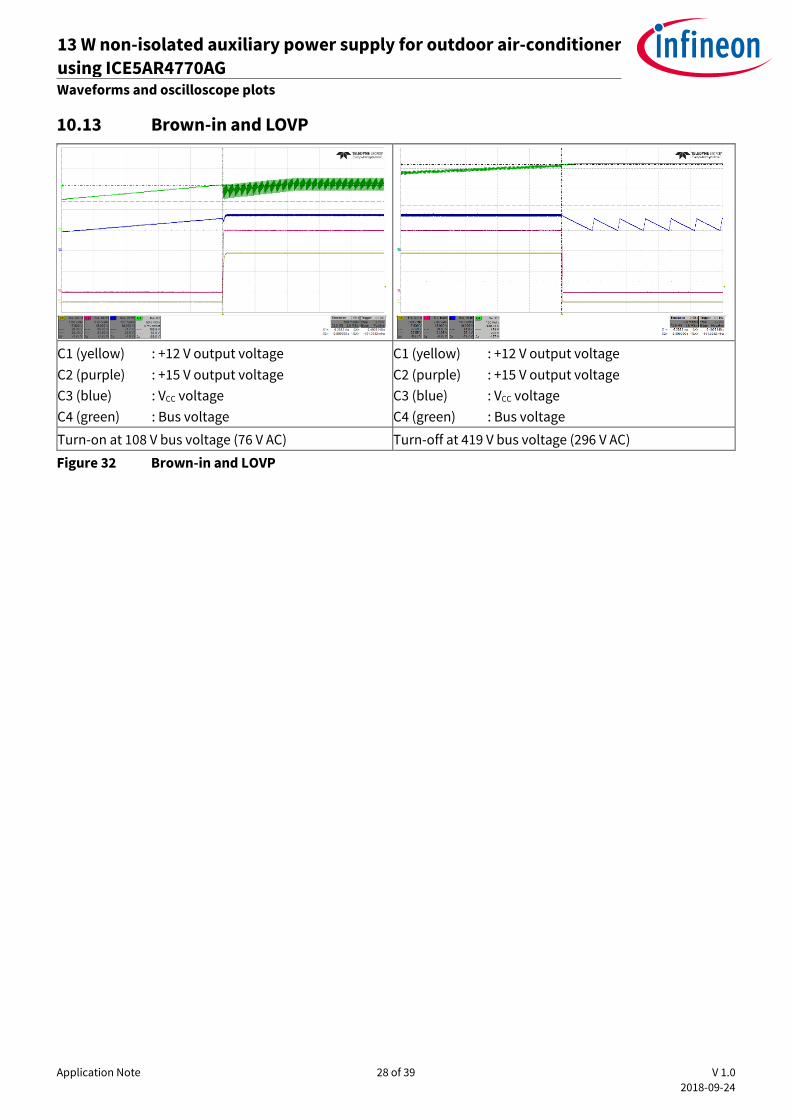
10.13 Brown-in and LOVP
C1 (yellow) : +12 V output voltage
C2 (purple) : +15 V output voltage
C3 (blue) : VCC voltage
C4 (green) : Bus voltage
C1 (yellow) : +12 V output voltage
C2 (purple) : +15 V output voltage
C3 (blue) : VCC voltage
C4 (green) : Bus voltage
Turn-on at 108 V bus voltage (76 V AC) Turn-off at 419 V bus voltage (296 V AC)
Figure 32 Brown-in and LOVP
Application Note 29 of 39 V 1.0
2018-09-24
13 W non-isolated auxiliary power supply for outdoor air-conditioner
using ICE5AR4770AG REF_5AR4770AG_13W1 Appendix A: Transformer design and spreadsheet [3]
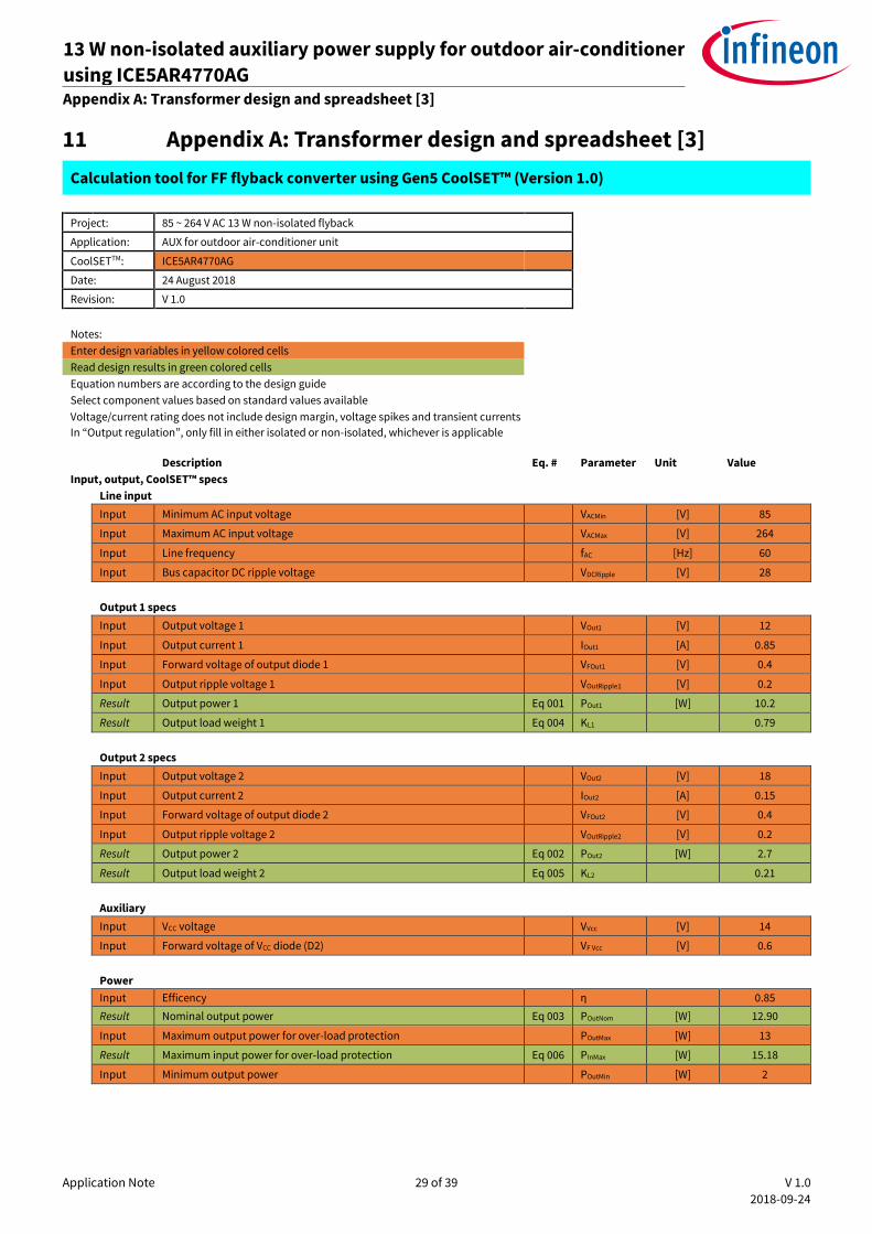
11 Appendix A: Transformer design and spreadsheet [3]
Calculation tool for FF flyback converter using Gen5 CoolSET™ (Version 1.0)
Project: 85 ~ 264 V AC 13 W non-isolated flyback
Application: AUX for outdoor air-conditioner unit
CoolSETTM: ICE5AR4770AG
Date: 24 August 2018
Revision: V 1.0
Notes:
Enter design variables in yellow colored cells
Read design results in green colored cells
Equation numbers are according to the design guide
Select component values based on standard values available
Voltage/current rating does not include design margin, voltage spikes and transient currents
In “Output regulation”, only fill in either isolated or non-isolated, whichever is applicable
Description Eq. # Parameter Unit Value
Input, output, CoolSET™ specs Line input
Input Minimum AC input voltage VACMin [V] 85
Input Maximum AC input voltage VACMax [V] 264
Input Line frequency fAC [Hz] 60
Input Bus capacitor DC ripple voltage VDCRipple [V] 28 Output 1 specs
Input Output voltage 1 VOut1 [V] 12
Input Output current 1 IOut1 [A] 0.85
Input Forward voltage of output diode 1 VFOut1 [V] 0.4
Input Output ripple voltage 1 VOutRipple1 [V] 0.2
Result Output power 1 Eq 001 POut1 [W] 10.2
Result Output load weight 1 Eq 004 KL1 0.79 Output 2 specs
Input Output voltage 2 VOut2 [V] 18
Input Output current 2 IOut2 [A] 0.15
Input Forward voltage of output diode 2 VFOut2 [V] 0.4
Input Output ripple voltage 2 VOutRipple2 [V] 0.2
Result Output power 2 Eq 002 POut2 [W] 2.7
Result Output load weight 2 Eq 005 KL2 0.21 Auxiliary
Input VCC voltage VVcc [V] 14
Input Forward voltage of VCC diode (D2) VF Vcc [V] 0.6 Power
Input Efficency η 0.85 Result Nominal output power Eq 003 POutNom [W] 12.90
Input Maximum output power for over-load protection POutMax [W] 13
Result Maximum input power for over-load protection Eq 006 PInMax [W] 15.18
Input Minimum output power POutMin [W] 2
Application Note 30 of 39 V 1.0
2018-09-24
13 W non-isolated auxiliary power supply for outdoor air-conditioner
using ICE5AR4770AG REF_5AR4770AG_13W1 Appendix A: Transformer design and spreadsheet [3]
Controller/CoolSET™
Controller/CoolSETTM ICE5AR4770AG Input Switching frequency fS [Hz] 100000
Input Targeted max. drain source voltage VDSMax [V] 700
Input Max. ambient temperature Tamax [°C] 50
Diode bridge and input capacitor Diode bridge
Input Power factor cosϕ 0.5 Result Maximum AC input current Eq 007 IACRMS [A] 0.357
Result Peak voltage at VACMax Eq 008 VDCMaxPk [V] 373.35 Input capacitor
Result Peak voltage at VACMin Eq 009 VDCMinPk [V] 120.21
Result Selected minimum DC input voltage Eq 010 VDCMinSet [V] 92.21
Result Discharging time at each half-line cycle Eq 011 TD [ms] 6.49
Result Required energy at discharging time of input capacitor Eq 012 WIn [Ws] 0.10
Result Calculated input capacitor Eq 013 CINCal [µF] 33.10
Input Select input capacitor (C1) Cin [µF] 33
Result Calculated minimum DC input voltage Eq 015 VDCMin [V] 92.11
Transformer design
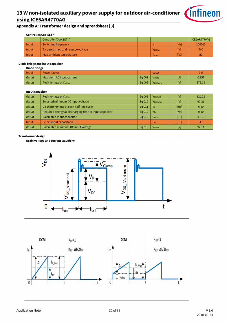
Drain voltage and current waveform
Application Note 31 of 39 V 1.0
2018-09-24
13 W non-isolated auxiliary power supply for outdoor air-conditioner
using ICE5AR4770AG REF_5AR4770AG_13W1 Appendix A: Transformer design and spreadsheet [3]
Primary inductance and winding currents
Input Reflection voltage VRSET [V] 95
Result Maximum duty cycle Eq 016 DMax 0.51
Input Select current ripple factor KRF 1
Result Primary inductance Eq 017 LP [H] 7.21E-04
Result Primary turn-on average current Eq 018 IAV [A] 0.32 Result Primary peak-to-peak current Eq 019 ΔI [A] 0.65 Result Primary peak current Eq 020 IPMax [A] 0.65
Result Primary valley current Eq 021 IValley [A] 0.00
Result Primary RMS current Eq 022 IPRMS [A] 0.267 Select core type
Input Select core type 10 Result Core type EE16/8/5 Result Core material TP4A(TDG) Result Maximum flux density BMax [T] 0.3
Result Cross-sectional area Ae [mm²] 20.1
Result Bobbin width BW [mm] 10.11
Result Winding cross-section AN [mm2] 24
Result Average length of turn lN [mm] 34
Winding calculation Result Calculated minimum number of primary turns Eq 023 NPCal Turns 77.56
Input Select number of primary turns NP Turns 84
Result Calculated number of secondary 1 turns Eq 024 NS1Cal Turns 10.96
Input Select number of secondary 1 turns NS1 Turns 11
Result Calculated number of secondary 2 turns Eq 025 NS2Cal Turns 16.27
Input Select number of secondary 2 turns NS2 Turns 16
Result Calculated number of auxiliary turns Eq 026 NVccCal Turns 12.95
Input Select number of auxiliary turns NVcc Turns 16
Result Calculated VCC voltage Eq 027 VVccCal [V] 17.44 Post calculation
Result Primary to secondary 1 turns ratio Eq 028 NPS1 7.64
Result Primary to secondary 2 turns ratio Eq 029 NPS2 5.25
Result Post-calculated reflected voltage Eq 030 VRPost [V] 94.69
Result Post-calculated maximum duty cycle Eq 031 DMaxPost 0.51
Result Duty cycle prime Eq 032 DMax' 0.49
Result Actual flux density Eq 033 BMaxAct [T] 0.277
Result Maximum DC input voltage for CCM operation Eq 034 VDCmaxCCM [V] 92.40 Transformer winding design
Input Margin according to safety standard M [mm] 0 Input Copper space factor fCu 0.4
Result Effective bobbin window Eq 035 BWE [mm] 10.1
Result Effective winding cross-section Eq 036 ANe [mm²] 24.0
Input Primary winding area factor AFNP 0.50
Input Secondary 1 winding area factor AFNS1 0.30
Input Secondary 2 winding area factor AFNS2 0.15
Input Auxiliary winding area factor AFNVcc 0.05
Application Note 32 of 39 V 1.0
2018-09-24
13 W non-isolated auxiliary power supply for outdoor air-conditioner
using ICE5AR4770AG REF_5AR4770AG_13W1 Appendix A: Transformer design and spreadsheet [3]
Primary winding
Result Calculated wire copper cross-sectional area Eq 037 APCal [mm²] 0.0571
Result Calculated maximum wire size Eq 038 AWGPCal 30
Input Select wire size AWGP 30
Input Select number of parallel wire nwP 1
Result Wire copper diameter Eq 039 dP [mm] 0.26
Result Wire copper cross-sectional area Eq 040 AP [mm2] 0.0517
Result Wire current density Eq 041 SP [A/mm2] 5.16
Input Insulation thickness INSP [mm] 0.01
Result Turns per layer Eq 042 NLP Turns/layer 36
Result Number of layers Eq 043 LnP Layers 3 Secondary 1 winding
Result Calculated wire copper cross-sectional area Eq 044 ANS1Cal [mm²] 0.2618
Result Calculated maximum wire size Eq 045 AWGS1Cal 23
Input Select wire size AWGS1 27
Input Select number of parallel wire nwS1 2
Result Wire copper diameter Eq 046 dS1 [mm] 0.3629
Result Wire copper cross-sectional area Eq 047 AS1 [mm2] 0.2069
Result Peak current Eq 048 IS1Max [A] 3.9189
Result RMS current Eq 049 IS1RMS [A] 1.5901
Result Wire current density Eq 050 SS1 [A/mm2] 7.69
Input Insulation thickness INSS1 [mm] 0.01
Result Turns per layer Eq 051 NLS1 Turns/layer 11
Result Number of layers Eq 052 LnS1 Layers 1
Secondary 2 winding
Result Calculated wire copper cross-sectional area Eq 053 ANS2Cal [mm²] 0.0900
Result Calculated maximum wire size Eq 054 AWGS2Cal 28
Input Select wire size AWGS2 30
Input Select number of parallel wire nwS2 1
Result Wire copper diameter Eq 055 dS2 [mm] 0.2566
Result Wire copper cross-sectional area Eq 056 AS2 [mm2] 0.0517
Result Peak current Eq 057 IS2Max [A] 0.7132
Result RMS current Eq 058 IS2RMS [A] 0.2894
Result Wire current density Eq 059 SS2 [A/mm2] 5.59
Input Insulation thickness INSS2 [mm] 0.01
Result Turns per layer Eq 060 NLS2 Turns/layer 36
Result Number of layers Eq 061 LnS2 Layers 1
RCD clamper and CS resistor RCD clamper circuit
Input Leakage inductance percentage LLK% [%] 1
Result Leakage inductance Eq 062 LLK [H] 7.21E-06
Result Clamping voltage Eq 063 VClamp [V] 231.96
Result Calculated clamping capacitor Eq 064 CClampCal [nF] 0.04
Input Select clamping capacitor value (C2) Cclamp [nF] 0.47
Result Calculated clamping resistor Eq 065 RclampCal [kΩ] 644.0
Input Select clamping resistor value (R4) Rclamp [kΩ] 240 CS resistor
Input CS threshold value from datasheet VCS_N [V] 0.8
Result Calculated current sense resistor (R8A, R8B) Eq 066 Rsense [Ω] 1.23
Application Note 33 of 39 V 1.0
2018-09-24
13 W non-isolated auxiliary power supply for outdoor air-conditioner
using ICE5AR4770AG REF_5AR4770AG_13W1 Appendix A: Transformer design and spreadsheet [3]
Output rectifier Secondary 1 Output rectifier
Result Diode reverse voltage Eq 067 VRDiode1 [V] 60.89
Result Diode RMS current IS 1RMS [A] 1.59
Input Max voltage undershoot at output capacitor ΔVOut1 [V] 0.3
Input Number of clock periods ncp1 20
Result Output capacitor ripple current Eq 068 IRipple1 [A] 1.34
Result Calculated minimum output capacitor Eq 069 COut1Cal [µF] 567
Input Select output capacitor value (C152) COut1 [µF] 680
Input ESR (Zmax) value from datasheet at 100 kHz RESR1 [Ω] 0.032
Input Number of parallel capacitors ncCOut1 1
Result Zero frequency of output capacitor Eq 070 fZCOut1 [kHz] 7.31
Result First-stage ripple voltage Eq 071 VRipple1 [V] 0.125404
Input Select LC filter inductor value (L151) Lout1 [µH] 2.2
Result Calculated LC filter capacitor Eq 072 CLCCal1 [µF] 215.2
Input Select LC filter capacitor value (C153) CLC1 [µF] 220
Result LC filter frequency Eq 073 fLC1 [kHz] 7.23
Result Second-stage ripple voltage Eq 074 V2ndRipple1 [mV] 0.65
Secondary 2 Output rectifier
Result Diode reverse voltage Eq 075 VRDiode2 [V] 89.11
Result Diode RMS current IS2RMS [A] 0.29
Input Max. voltage undershoot at output capacitor ΔVOut1 [V] 0.15
Input Number of clock periods ncp2 20
Result Output capacitor ripple current Eq 076 IRipple2 [A] 0.25
Result Calculated minimum output capacitor Eq 077 COut2Cal [µF] 200
Input Select output capacitor value (C152) COut2 [µF] 220
Input ESR (Zmax) value from datasheet at 100 kHz RESR2 [Ω] 0.032
Input Number of parallel capacitors ncCOut2 1
Result Zero-frequency of output capacitor Eq 078 fZCOut2 [kHz] 22.61
Result First-stage ripple voltage Eq 079 VRipple2 [V] 0.02
VCC diode and capacitor VCC diode and capacitor
Result Auxiliary diode reverse voltage (D2) Eq 083 VRDiodeVCC [V] 88.55
Input Soft-start time from datasheet tss [ms] 12
Input IVCC,Charge3 from datasheet IVCC_Charge3 [mA] 3
Input VCC on-threshold VVCC_ON [V] 16
Input VCC off-threshold VVCC_OFF [V] 10
Result Calculated VCC capacitor Eq 084 CVCCCal [µF] 6.00
Input Select VCC capacitor (C3) CVCC [µF] 22
Input VCC short threshold from datasheet VVCC_SCP [V] 1.1
Input IVCC_Charge1 from datasheet IVCC_Charge1 [mA] 0.2
Result Start-up time Eq 085 tStartUp [ms] 230.267
Calculation of losses Input diode bridge
Input Diode bridge forward voltage VFBR [V] 1
Result Diode bridge power loss Eq 086 PDIN [W] 0.71 Transformer copper
Result Primary winding copper resistance Eq 087 RPCu [mΩ] 949.56
Result Secondary 1 winding copper resistance Eq 088 RS1Cu [mΩ] 31.10
Result Secondary 2 winding copper resistance Eq 089 RS2Cu [mΩ] 180.87
Application Note 34 of 39 V 1.0
2018-09-24
13 W non-isolated auxiliary power supply for outdoor air-conditioner
using ICE5AR4770AG REF_5AR4770AG_13W1 Appendix A: Transformer design and spreadsheet [3]
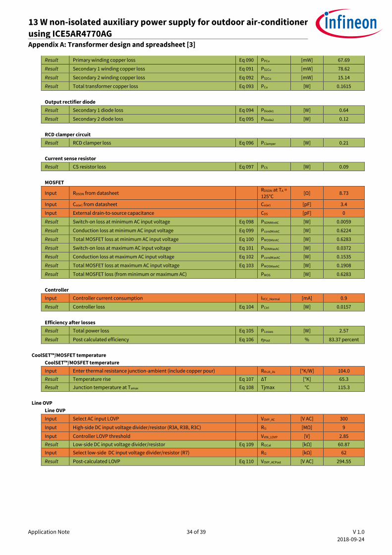
Result Primary winding copper loss Eq 090 PPCu [mW] 67.69
Result Secondary 1 winding copper loss Eq 091 PS1Cu [mW] 78.62
Result Secondary 2 winding copper loss Eq 092 PS2Cu [mW] 15.14
Result Total transformer copper loss Eq 093 PCu [W] 0.1615 Output rectifier diode
Result Secondary 1 diode loss Eq 094 PDiode1 [W] 0.64
Result Secondary 2 diode loss Eq 095 PDiode2 [W] 0.12 RCD clamper circuit
Result RCD clamper loss Eq 096 PClamper [W] 0.21 Current sense resistor
Result CS resistor loss Eq 097 PCS [W] 0.09 MOSFET
Input RDSON from datasheet RDSON at TA = 125°C
[Ω] 8.73
Input Co(er) from datasheet Co(er) [pF] 3.4
Input External drain-to-source capacitance CDS [pF] 0
Result Switch-on loss at minimum AC input voltage Eq 098 PSONMinAC [W] 0.0059
Result Conduction loss at minimum AC input voltage Eq 099 PcondMinAC [W] 0.6224
Result Total MOSFET loss at minimum AC input voltage Eq 100 PMOSMinAC [W] 0.6283
Result Switch-on loss at maximum AC input voltage Eq 101 PSONMaxAC [W] 0.0372
Result Conduction loss at maximum AC input voltage Eq 102 PcondMaxAC [W] 0.1535
Result Total MOSFET loss at maximum AC input voltage Eq 103 PMOSMaxAC [W] 0.1908
Result Total MOSFET loss (from minimum or maximum AC) PMOS [W] 0.6283 Controller
Input Controller current consumption IVCC_Normal [mA] 0.9
Result Controller loss Eq 104 PCtrl [W] 0.0157 Efficiency after losses
Result Total power loss Eq 105 PLosses [W] 2.57
Result Post calculated efficiency Eq 106 ηPost % 83.37 percent
CoolSET™/MOSFET temperature CoolSET™/MOSFET temperature
Input Enter thermal resistance junction-ambient (include copper pour) RthJA_As [°K/W] 104.0 Result Temperature rise Eq 107 ΔT [°K] 65.3 Result Junction temperature at Tamax Eq 108 Tjmax °C 115.3
Line OVP Line OVP
Input Select AC input LOVP VOVP_AC [V AC] 300
Input High-side DC input voltage divider/resistor (R3A, R3B, R3C) RI1 [MΩ] 9
Input Controller LOVP threshold VVIN_LOVP [V] 2.85 Result Low-side DC input voltage divider/resistor Eq 109 RI2Cal [kΩ] 60.87 Input Select low-side DC input voltage divider/resistor (R7) RI2 [kΩ] 62
Result Post-calculated LOVP Eq 110 VOVP_ACPost [V AC] 294.55
Application Note 35 of 39 V 1.0
2018-09-24
13 W non-isolated auxiliary power supply for outdoor air-conditioner
using ICE5AR4770AG REF_5AR4770AG_13W1 Appendix A: Transformer design and spreadsheet [3]
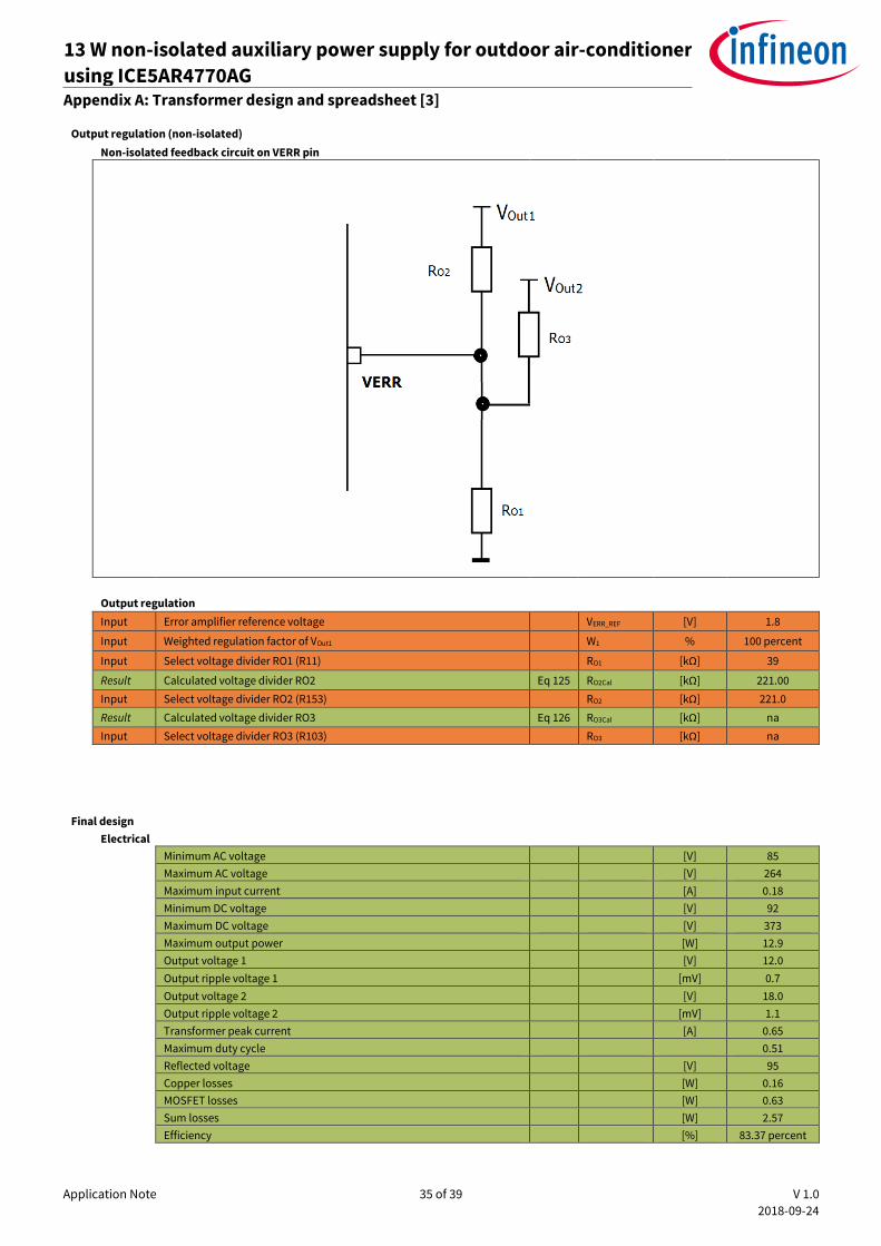
Output regulation (non-isolated)
Non-isolated feedback circuit on VERR pin
Output regulation
Input Error amplifier reference voltage VERR_REF [V] 1.8
Input Weighted regulation factor of VOut1 W1 % 100 percent
Input Select voltage divider RO1 (R11) RO1 [kΩ] 39
Result Calculated voltage divider RO2 Eq 125 RO2Cal [kΩ] 221.00 Input Select voltage divider RO2 (R153) RO2 [kΩ] 221.0 Result Calculated voltage divider RO3 Eq 126 RO3Cal [kΩ] na Input Select voltage divider RO3 (R103) RO3 [kΩ] na
Final design
Electrical
Minimum AC voltage [V] 85
Maximum AC voltage [V] 264
Maximum input current [A] 0.18
Minimum DC voltage [V] 92
Maximum DC voltage [V] 373
Maximum output power [W] 12.9
Output voltage 1 [V] 12.0
Output ripple voltage 1 [mV] 0.7
Output voltage 2 [V] 18.0
Output ripple voltage 2 [mV] 1.1
Transformer peak current [A] 0.65
Maximum duty cycle 0.51
Reflected voltage [V] 95
Copper losses [W] 0.16
MOSFET losses [W] 0.63
Sum losses [W] 2.57
Efficiency [%] 83.37 percent
Application Note 36 of 39 V 1.0
2018-09-24
13 W non-isolated auxiliary power supply for outdoor air-conditioner
using ICE5AR4770AG REF_5AR4770AG_13W1 Appendix A: Transformer design and spreadsheet [3]
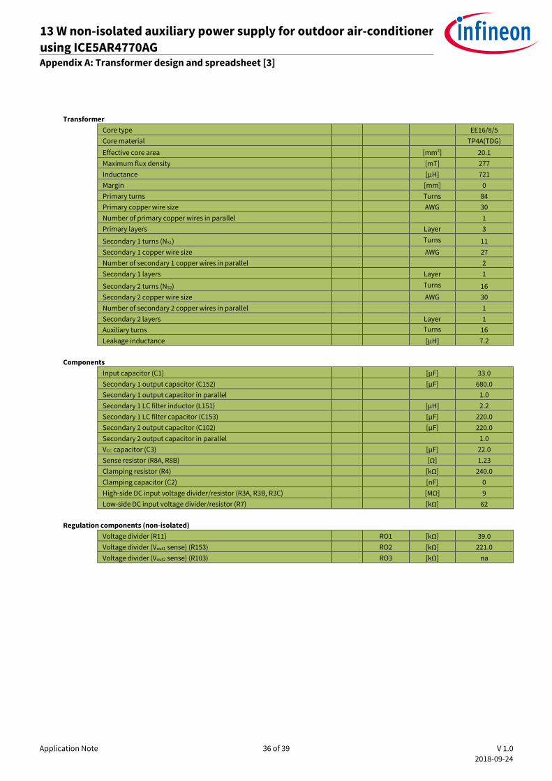
Transformer
Core type EE16/8/5
Core material TP4A(TDG)
Effective core area [mm2] 20.1
Maximum flux density [mT] 277
Inductance [µH] 721
Margin [mm] 0
Primary turns Turns 84
Primary copper wire size AWG 30
Number of primary copper wires in parallel 1
Primary layers Layer 3
Secondary 1 turns (NS1) Turns 11
Secondary 1 copper wire size AWG 27
Number of secondary 1 copper wires in parallel 2
Secondary 1 layers Layer 1
Secondary 2 turns (NS2) Turns 16
Secondary 2 copper wire size AWG 30
Number of secondary 2 copper wires in parallel 1
Secondary 2 layers Layer 1
Auxiliary turns Turns 16
Leakage inductance [µH] 7.2
Components
Input capacitor (C1) [µF] 33.0
Secondary 1 output capacitor (C152) [µF] 680.0
Secondary 1 output capacitor in parallel 1.0
Secondary 1 LC filter inductor (L151) [µH] 2.2
Secondary 1 LC filter capacitor (C153) [µF] 220.0
Secondary 2 output capacitor (C102) [µF] 220.0
Secondary 2 output capacitor in parallel 1.0
VCC capacitor (C3) [µF] 22.0
Sense resistor (R8A, R8B) [Ω] 1.23
Clamping resistor (R4) [kΩ] 240.0
Clamping capacitor (C2) [nF] 0
High-side DC input voltage divider/resistor (R3A, R3B, R3C) [MΩ] 9
Low-side DC input voltage divider/resistor (R7) [kΩ] 62
Regulation components (non-isolated)
Voltage divider (R11) RO1 [kΩ] 39.0
Voltage divider (Vout1 sense) (R153) RO2 [kΩ] 221.0
Voltage divider (Vout2 sense) (R103) RO3 [kΩ] na
Application Note 37 of 39 V 1.0
2018-09-24
13 W non-isolated auxiliary power supply for outdoor air-conditioner
using ICE5AR4770AG REF_5AR4770AG_13W1 References
12 References
[1] ICE5xRxxxxAG datasheet
[2] Design guide fifth-generation fixed-frequency design guide – ICE5xSAG and ICE5xRxxxxAG
[3] Calculation tool – ICE5xSAG and ICE5xRxxxxAG
Application Note 38 of 39 V 1.0
2018-09-24
13 W non-isolated auxiliary power supply for outdoor air-conditioner
using ICE5AR4770AG REF_5AR4770AG_13W1 Revision history
Revision history
Document
version
Date of release Description of changes
V 1.0 24 Sept 2018 First release

Trademarks All referenced product or service names and trademarks are the property of their respective owners.
Edition 2018-09-24
AN_1809_PL83_1810_045410
Published by
Infineon Technologies AG
81726 Munich, Germany
© 2018 Infineon Technologies AG.
All Rights Reserved.
Do you have a question about this
document?
Email: [email protected]
Document reference
IMPORTANT NOTICE The information contained in this application note is given as a hint for the implementation of the product only and shall in no event be regarded as a description or warranty of a certain functionality, condition or quality of the product. Before implementation of the product, the recipient of this application note must verify any function and other technical information given herein in the real application. Infineon Technologies hereby disclaims any and all warranties and liabilities of any kind (including without limitation warranties of non-infringement of intellectual property rights of any third party) with respect to any and all information given in this application note. The data contained in this document is exclusively intended for technically trained staff. It is the responsibility of customer’s technical departments to evaluate the suitability of the product for the intended application and the completeness of the product information given in this document with respect to such application.
For further information on the product, technology, delivery terms and conditions and prices please contact your nearest Infineon Technologies office (www.infineon.com).
WARNINGS Due to technical requirements products may contain dangerous substances. For information on the types in question please contact your nearest Infineon Technologies office. Except as otherwise explicitly approved by Infineon Technologies in a written document signed by authorized representatives of Infineon Technologies, Infineon Technologies’ products may not be used in any applications where a failure of the product or any consequences of the use thereof can reasonably be expected to result in personal injury.