Embed Size (px)
Citation preview
IEEE TRANSACTIONS ON POWER ELECTRONICS, VOL. 24, NO. 7, JULY 2009 1747
Providing Ride-Through Capability to a Doubly FedInduction Generator Under Unbalanced Voltage Dips
David Santos-Martin, Jose Luis Rodriguez-Amenedo, and Santiago Arnaltes, Member, IEEE
Abstract—This paper analyzes the effect of unbalanced volt-age over doubly fed induction generators (DFIGs) and presents anovel control strategy, named dynamic programming power con-trol plus (DPPC+), based on dynamic programming control. Thehigh penetration of wind energy in the electrical grids demandsfor new requirements for the operation of wind energy conversionsystems (WECSs). DFIG is the most employed WECS, and theDPPC+ guarantees their operation under unbalance conditionsachieving the required objectives. Although the technique can beimplemented to control both rotor and grid converters, we herebyexpound the former, which regulates stator active and reactivepower. The validation of the results obtained with DPPC+ hasbeen performed through the use of experimental tests on a 20-kWtest bench, consisting of a DFIG and induction motor drive. Theobtained results show that the DPPC+ is suitable for achievinga good dynamic response while controlling current distortion andpower and/or torque oscillations for both steady-state conditionsand unbalanced voltage dips, showing the low-voltage ride-throughcapability.
Index Terms—Doubly fed induction generator (DFIG), dynamicprogramming power control plus (DPPC+), unbalanced voltage,voltage dip.
I. INTRODUCTION
IN THE LAST few years, large-scale integration of windenergy has become a fact due to social and geopolitical
concerns. In electrical terms, the evolution from short-circuitinduction generators and wound rotor induction generators withsupersynchronous cascade has reached its end with the intro-duction of doubly fed induction generators (DFIGs, or doublyfed asynchronous generators) with bidirectional and partiallyrated power inverters.
The application of known control techniques, such as flux-oriented vector control, has proved sufficient until now forthe accomplishment of the initial requirements. Grid operators,wind farm owners, and large-scale installations of wind powerare redefining these specifications and aim to increase the qual-ity and robustness of the systems during normal and perturbedoperation. Advanced control techniques are required to matchthese new needs.
The first wind turbine control systems were designed to dealwith normal operational conditions optimizing power electronicsizing and time design development. Vector control has been themost popular control technique, through its rotational transfor-
Manuscript received June 27, 2008; revised October 27, 2008. Current versionpublished July 22, 2009. Recommended for publication by Associate EditorZ. Chen.
The authors are with the Department of Electrical Engineering, UniversityCarlos III of Madrid, Madrid 28911, Spain.
Color versions of one or more of the figures in this paper are available onlineat http://ieeexplore.ieee.org.
Digital Object Identifier 10.1109/TPEL.2009.2016965
mations, but its linear nature and lack of robustness when facingchanges in operational conditions are its main drawback.
Due to both the nonlinear nature of the inverter, with finitepossible states, and the linear time-varying nature of the ma-chine model, nonlinear control techniques, such as direct torquecontrol (DTC) or direct power control (DPC) [1]–[3] have beenproposed in recent years. The main advantages of direct con-trol are its high dynamics, its performance robustness that de-pends solely on input error and rotor position, and its simplicityof implementation. The drawbacks are an important torque orpower ripple due to its high bandwidth and an inherently variableswitching spectrum that varies with rotor speed and operationalconditions, and where special care must be taken for the even-tuality of a near zero slip.
Many methods have been proposed to solve these problems.This paper uses a novel approach to control DFIGs. The dynamicprogramming power control plus (DPPC+) applies the Bellmantheory [4] for optimal control of discrete-time systems, andresults in a closed loop, which is generally nonlinear, and afeedback scheme. The method defines a quadratic time-domainperformance criterion or cost function that determines the best oroptimum policy from any operation point to another, accordingto the previously defined performance function and applying thecorrect converter switches sequence.
Many wind turbines are connected in weak areas where heavyunsymmetrical loads, unsymmetrical transformer windings, ortransmission impedance and transient faults (voltage dip) willbe typical sources of unbalanced operation mode [5]. This willaffect any generator with direct coupling to the grid such asrotor short circuited or DFIGs, causing, in standard operation,unequal unbalanced nonsinusoidal output currents with unequalheating and power loss and torque or power pulsations, thusincreasing the fatigue on mechanical components [6]. In thecase of the DFIG, it may even lead to a loss of control due tohigher power demands for the inverters if no special rating isconsidered.
Many studies have focused the impact of voltage unbalance oninduction machines such as motors or generators. All of themhave shown high rotor losses even for slight unbalance and,therefore, lead us to calculate the necessary derating factor forthe machine as presented in [6]–[8]. Another topic of researchfor these machines is the analysis of torque pulsations [9].
Voltage unbalance also affects the power converters due to thedistortion of output currents or dc-link voltage ripple [10], [11],and strategies to minimize these effects have been proposed.
The DFIG has also been analyzed for grid-connected or stand-alone operation [12] under unbalanced grid voltage. Under-standing the generator functioning and focusing targets for new
0885-8993/$26.00 © 2009 IEEE
1748 IEEE TRANSACTIONS ON POWER ELECTRONICS, VOL. 24, NO. 7, JULY 2009
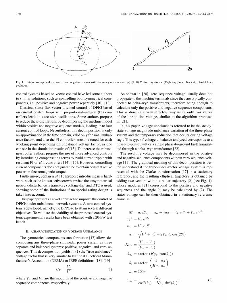
Fig. 1. Stator voltage and its positive and negative vectors with stationary reference (α, β). (Left) Vector trajectories. (Right) θ1 (dotted line), θu s (solid line)evolution.
control systems based on vector control have led some authorsto similar solutions, such as controlling both symmetrical com-ponents, i.e., positive and negative power separately [10], [13].
Classical stator-flux-vector-oriented control of DFIG basedon current control loops with proportional–integral (PI) con-trollers leads to excessive oscillations. Some authors proposeto reduce these oscillations by decomposing the machine modelwithin positive and negative sequence models, leading up to fourcurrent control loops. Nevertheless, this decomposition is onlyan approximation in the time domain, valid only for small unbal-ance factors, and also the PI controllers must be tuned for eachworking point depending on unbalance voltage factor, as onecan see in the simulation results of [13]. To increase the robust-ness, other authors propose the use of more advanced controlsby introducing compensating terms to avoid current ripple withresonant PI or H∞ controllers [14], [15]. However, controllingcurrent components does not guarantee to obtain constant activepower or electromagnetic torque.
Furthermore, Seman et al. [16] propose introducing new hard-ware, such as the known active crowbar when the unsymmetricalnetwork disturbance is transitory (voltage dip) and DTC is used,showing some of the limitations if no special rating design istaken into account.
This paper presents a novel approach to improve the control ofDFIGs under unbalanced network systems. A new control sys-tem is developed, namely, the DPPC+, to attain several differentobjectives. To validate the viability of the proposed control sys-tem, experimental results have been obtained with a 20-kW testbench.
II. CHARACTERIZATION OF VOLTAGE UNBALANCE
The symmetrical components transformation [17] allows de-composing any three-phase sinusoidal power system as threeseparate and balanced systems: positive, negative, and zero se-quences. This decomposition yields in (1) the “true unbalance”voltage factor that is very similar to National Electrical Manu-facturer’s Association (NEMA) or IEEE definitions [18], [19]
UF =V−V+
(1)
where V+ and V− are the modulus of the positive and negativesequence components, respectively.
As shown in [20], zero sequence voltage usually does notpropagate to the machine terminals since they are typically con-nected to delta–wye transformers, therefore being enough tocalculate only the positive and negative sequence components.This is done in a very effective way using only rms valuesof the line-to-line voltage, similar to the algorithm proposedin [21].
In this paper, voltage unbalance is referred to be the steady-state voltage magnitude unbalance variation of the three-phasesystem and the temporary reduction that occurs during voltagesags. This type of voltage unbalance analyzed corresponds to aphase-to-phase fault or a single phase-to-ground fault transmit-ted through a delta–wye transformer [22].
The resulting voltage may be decomposed in the positiveand negative sequence components without zero sequence volt-age [11]. The graphical meaning of this decomposition is bet-ter understood if the three-space-vector voltage system is rep-resented with the Clarke transformation [17] in a stationaryreference, and the resulting elliptical trajectory is obtained byadding two vectors with a circular trajectory (2) (see Fig. 1),whose modules [21] correspond to the positive and negativesequences and the angle θ1 may be calculated by (2). Thestator voltage can be then obtained in a stationary referenceframe as
us = us � θus= uα + juβ = V+ ejθ1 + V− e−jθ1
us+ = V+ ejθ1
us− = V− e−jθ1
us =√
V 2+ + V 2
− + 2V+V− cos(2θ1)
KUF=
(V+ − V−)(V+ + V−)
θus= arctan (KUF
tan(θ1))
θ1 = arctan(
1KUF
uβ
uα
)ω1 = 100π
ωus=
KUF
cos2(θ1) + K2UF
sin2(θ1)ω1 (2)
SANTOS-MARTIN et al.: PROVIDING RIDE-THROUGH CAPABILITY TO A DFIG UNDER UNBALANCED VOLTAGE DIPS 1749
where V+ and V− are the constant positive and negative statorvoltage components, θ1 is the V+ vector angle, and ω1 is itsconstant first harmonic grid pulsation (Fig. 1).
III. POWER DEFINITION UNDER UNBALANCE CONDITIONS
A common method for calculating the active and reactivepower for control purposes is by the instantaneous power defi-nition that is based on the space voltage and current vectors
us = us � θus
is = is � θis
Ps = us is = usis cos(θus− θis
)
Qs =∣∣us ∧ is
∣∣ = usis sin(θus− θis
). (3)
As shown, Ps and Qs do not depend on the reference frame.From (3)
P 2s + Q2
s = u2s i
2s
θis= θus
− arctan(
Qs
Ps
). (4)
It can be seen in (4) that to achieve constant active and reactivepower Ps and Qs , as the stator voltage module us varies (2)and its angle θus
has no constant speed (see Fig. 1), the statorcurrent cannot be sinusoidal. Therefore, the current module willbe variable as well as its angle will be similar to the stator voltageangle. On the other hand, if the objective is to obtain a sinusoidalstator current, with constant module is and constant speed ofθis
, the active and reactive power will vary as a consequence ofthe stator voltage variations.
From (2) and (3), the stator active and reactive power can alsobe expressed as
Ps = us is = V+ is cos(θip) + V−is cos(−2θ1 + θip)
P+ = V+ is cos(θip)
P− = V−is cos(−2θ1 + θip) (5)
where P+ and P− are proportional to the projections of the statorcurrent is over us
+ and us−
Qs =∣∣us ∧ is
∣∣ = V+ is sin(θip) + V−is sin(−2θ1 + θip)
Q+ = V+ is sin(θip)
Q− = V−is sin(−2θ1 + θip) (6)
where Q+ and Q− are proportional to the projections of thestator current is over the us
+ and us− quadrature components.
The stator active and reactive power are obtained as the addi-tion of these projection terms
Ps = P+ + P−
Qs = Q+ + Q−. (7)
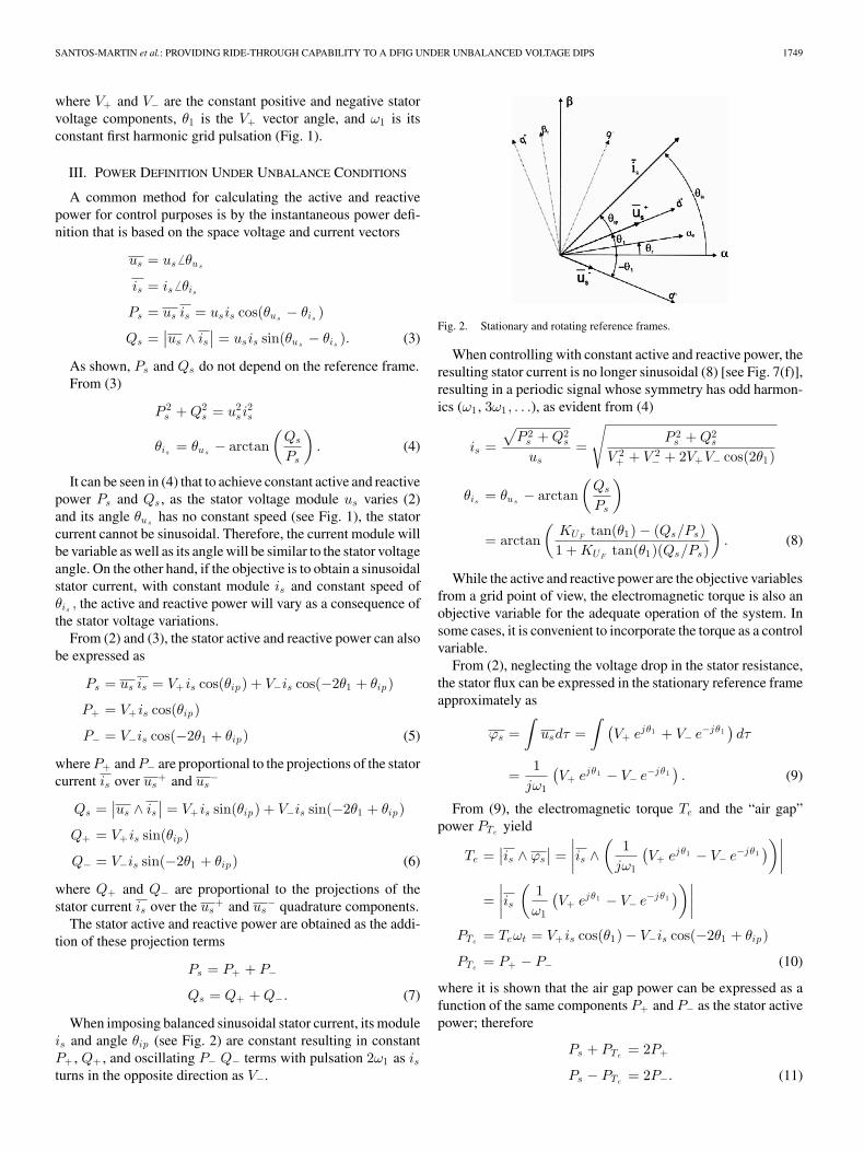
When imposing balanced sinusoidal stator current, its moduleis and angle θip (see Fig. 2) are constant resulting in constantP+ , Q+ , and oscillating P− Q− terms with pulsation 2ω1 as isturns in the opposite direction as V−.
Fig. 2. Stationary and rotating reference frames.
When controlling with constant active and reactive power, theresulting stator current is no longer sinusoidal (8) [see Fig. 7(f)],resulting in a periodic signal whose symmetry has odd harmon-ics (ω1 , 3ω1 , . . .), as evident from (4)
is =
√P 2
s + Q2s
us=
√P 2
s + Q2s
V 2+ + V 2
− + 2V+V− cos(2θ1)
θis= θus
− arctan(
Qs
Ps
)
= arctan(
KUFtan(θ1) − (Qs/Ps)
1 + KUFtan(θ1)(Qs/Ps)
). (8)
While the active and reactive power are the objective variablesfrom a grid point of view, the electromagnetic torque is also anobjective variable for the adequate operation of the system. Insome cases, it is convenient to incorporate the torque as a controlvariable.
From (2), neglecting the voltage drop in the stator resistance,the stator flux can be expressed in the stationary reference frameapproximately as
ϕs =∫
usdτ =∫ (
V+ ejθ1 + V− e−jθ1)dτ
=1
jω1
(V+ ejθ1 − V− e−jθ1
). (9)
From (9), the electromagnetic torque Te and the “air gap”power PTe
yield
Te =∣∣is ∧ ϕs
∣∣ =∣∣∣∣is ∧
(1
jω1
(V+ ejθ1 − V− e−jθ1
))∣∣∣∣=
∣∣∣∣is(
1ω1
(V+ ejθ1 − V− e−jθ1
))∣∣∣∣PTe
= Teωt = V+ is cos(θ1) − V−is cos(−2θ1 + θip)
PTe= P+ − P− (10)
where it is shown that the air gap power can be expressed as afunction of the same components P+ and P− as the stator activepower; therefore
Ps + PTe= 2P+
Ps − PTe= 2P−. (11)
1750 IEEE TRANSACTIONS ON POWER ELECTRONICS, VOL. 24, NO. 7, JULY 2009
As P− is always oscillating with frequency −2ω1 + ωip , (11)shows how only active power or electromagnetic torque can beconstant, but never both simultaneously.
Operating with the instantaneous power theory allows con-trolling the DFIG under voltage unbalance by detecting thepower pulsations at 2ω1 in contrast to phasor theory that doesnot consider this frequency.
IV. CONCEPT OF DPPC+ UNDER UNBALANCE GRID VOLTAGE
In DFIGs, the rotor side inverter, working as a voltage source,controls the stator active and reactive power directly by meansof the rotor flux and applying the appropriate voltage vector.
The natural control objectives for DPPC+, when applied tothe rotor converter, are to maintain the injected stator power inthe grid constant. Under unbalanced grid voltage, this target isnot so obvious if the resulting stator current is no longer si-nusoidal (8). Therefore, during this perturbed operation mode,different targets can be defined: 1) inject constant active andreactive power; 2) injecting sinusoidal stator currents; 3) main-taining the electromagnetic torque, or its equivalent, the air gappower constant while maintaining the reactive power constant;and 4) injecting stator current while the active and reactive powerhave as little ripple as possible.
A. General Concept
In a general case, the approximated dynamic behavior of asystem in the discrete state space notation is
xk+1 = xk + τf(xk , uk , kτ) (12)
where x is the process state, u the control input, τ the samplingperiod, k the sample index, and kτ the discrete time.
As in the conventional optimum control technique, the controlinput u may be chosen to minimize a specified performancecriterion
J =12
N −1∑k=0
τr(xk , uk , kτ) + s(xN ) (13)
where functions r and s define the dynamic behavior and thecost of control.
Determining the optimum control law for nonquadratic per-formance criteria or nonlinear process must be approachedthrough dynamic programming, or perhaps, calculus of vari-ations.
The algorithm DPPC+ applies the Bellman theory [4] foroptimal control of discrete-time systems, which considers anoptimal policy as the succession of optimal decisions.
It is assumed that x can evolve only to a finite number ofstates. At each stage, the optimal control problem is solved overa fixed length horizon of sampling periods, starting from thecurrent stage. At every sampling time, the first component of thecorresponding optimal policy is then used as the control factor ofthe current stage, while the remaining components are discarded.The process is then repeated at the next stage once it is revealed.This lookahead and rolling horizon approach is typically notoptimal, but of high performance and low computation cost.
The simplest possibility is to use a one-step lookahead policywhere the horizon is one stage that corresponds to one samplingperiod.
B. Discrete Dynamic Model of DFIG
The approximated dynamic behavior of a system is neededin order to apply the DPPC+ strategy to the DFIG. The dis-crete state space notation is chosen to represent the dq machinemodel referred to the synchronous reference, where the d-axisis aligned with the stator voltage vector, which is convenientto obtain the power directly by projecting the current vector.This model, usually used for balanced grid voltage, is still validfor unbalanced network where the machine electrical variables,currents, fluxes, or voltages can be something other than sinu-soids
X(k + 1) − X(k) = τA(k)X(k) + τBU(k)
Y (k) = (C+(k) + C−(k))X(k) (14)
where the discrete time notation kτ is simplified by the in-dex k, X = [isd , isq , ird , irq ]T is the process state vector con-taining the stator and rotor currents, and U = [us, ur ]T =[usd, 0, urd , urq ]T is the input vector containing the sta-tor and rotor voltages. The output vector Y = [Ps Qs ]T =[P+ + P− Q+ + Q−]T contains the instantaneous stator activeand reactive power, τ is the sampling period, A(k) is a time-varying matrix that depends on rotor speed, although it can alsobe considered constant within short periods of time due to highrotor inertia, B is a constant matrix in case of neglecting satu-rations, and C+(k) and C−(k) are time-varying matrix (see theAppendix for matrix definitions).
Therefore, using (14), it can be demonstrated that the differ-ence equation for the output vector is
∆Y+ =[
P+(k + 1) − P+(k)
Q+(k + 1) − Q+(k)
]
= τC+(k)(A(k)X(k) + BU(k)) + τ∆C+(k)X(k)
∆Y− =[
P−(k + 1) − P−(k)
Q−(k + 1) − Q−(k)
]= τC−(k)(A(k)X(k)
+ BU(k)) + τ∆C−(k)X(k). (15)
When defining
m0+(k) = C+(k)(A(k)X(k) + usdBIn1) + ∆C+(k)X(k)
mu+(k) = C+(k)BIn2
m0−(k) = C−(k)(A(k)X(k) + usdBIn1) + ∆C−(k)X(k)
mu−(k) = C−(k)BIn2 (16)
where In1 = [1, 1, 0, 0] and In2 = [0, 0, 1, 1], from (15) and(16) [
∆P+(k)
∆Q+(k)
]=
(m0+(k) + mu+(k)
[urd(k)
urq (k)
])τ
[∆P−(k)
∆Q−(k)
]=
(m0−(k) + mu−(k)
[urd(k)
urq (k)
])τ. (17)
SANTOS-MARTIN et al.: PROVIDING RIDE-THROUGH CAPABILITY TO A DFIG UNDER UNBALANCED VOLTAGE DIPS 1751
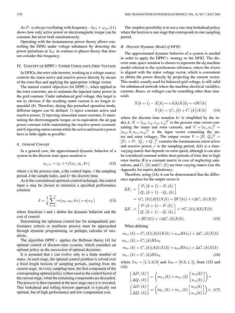
Fig. 3. Simulated power possible increments when applying V1 vector.
The power increment is, for a short period of time, a lin-ear function with a slope that depends on the applied rotorvoltage m0(k) and mu (17). This result is only valid whenconsidering average values within the discrete time. As is wellknown, a two-level inverter provides eight possible switchingstates, made up of six active, V1,...,6 , and two zero, V0,7 , in-verter voltage vectors. Operating with the rotating transforma-tion and the conversions gained from inverter switching statesto voltages, the rotor voltage [urdq (k)] can be expressed interms of the switching states (Tsa , Tsb , Tsc ) and the slip angle[urdq (Tsa , Tsb , Tsc , θslip)]. For each vector Vi , from (17), theinstantaneous power increment can be obtained. In Fig. 3, ac-tive and reactive power increments are presented showing a 90◦
degree shift for the reactive power. The pattern shown in Fig. 3is repeated for the other vectors V2−6 with a 60◦ degree shiftamong them. For the V0 vector, the possible increment is similarto the other six eliminating the frequency that corresponds to theslip.
There are then only seven possible slopes that dependon the rotor slip angle describing periodic values, whenusing the synchronous reference. How the choice of vec-tor Vi will determine the slopes for both active and re-active power must be considered when choosing a prioritystrategy.
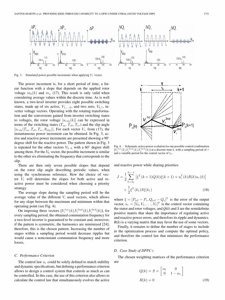
The average slope during the sampling period will be theaverage value of the different Vi used vectors, which allowsfor any slope between the maximum and minimum within thatoperating point (see Fig. 4).
On imposing three vectors [V 1sti (k),V 2nd
i (k),V 3rdi (k)], for
every sampling period, the obtained commutation frequency fora two-level inverter is guaranteed to be constant and, moreover,if the pattern is symmetric, the harmonics are minimized [24];therefore, this is the chosen pattern. Increasing the number ofstages within a sampling period would decrease ripples butwould cause a nonconstant commutation frequency and morelosses.
C. Performance Criterion
The control law ur could be solely defined to match stabilityand dynamic specifications, but defining a performance criterionallows to design a control system that controls as much as canbe controlled. In this case, the use of this criterion also allows tocalculate the control law that simultaneously evolves the active
Fig. 4. Schematic active power evolution for one possible control combination[V 1st
i (k),V 2ndi (k),V 3rd
i (k)] at a discrete time k, with a sampling period of τand a variable period for the central vector of tk .
and reactive power while sharing priorities
J =12
k1 −1∑k=k0
[ξT (k + 1)Q(k)ξ(k + 1) + uT
r (k)R(k)ur (k)]
+12ξT (k1)Sξ(k1) (18)
where ξ = [Pref − Ps,Qref − Qs ]T is the error of the outputvector, ur = [V0 , V1 , . . . , V7 ]T is the control vector containingthe stator and rotor voltages, and Q(k) and S are the semidefinitepositive matrix that share the importance of regulating activeand reactive power errors, and therefore its ripple and dynamics.R(k) is a varying matrix that may favor the use of some vectors.
Finally, it remains to define the number of stages to includein the optimization process and compute the optimal policy,and therefore the control law that minimizes the performancecriterion.
D. Case Study of DPPC+
The chosen weighting matrices of the performance criterionare
Q(k) = S =[
α1 00 1 − α1
]
R(k) = 0 (19)
1752 IEEE TRANSACTIONS ON POWER ELECTRONICS, VOL. 24, NO. 7, JULY 2009
where α1 = 0.5 to balance the importance of active and reactivepower variations.
DPPC+ is exemplified with the use of one-step lookaheadpolicy, one stage per sampling period, which results in a subsetof promising controls by dividing the one-step time in a discretegrid, where three vectors can be applied (see Fig. 4) with asymmetric pattern where the first and third vectors are the same.
The prediction horizon may be defined with two or morestages but the complexity to solve the performance criterionis increased highly, forcing, in practice, to use higher samplingperiods. The use of more stages could be interesting for trackingcontrols with time-varying references, i.e., ramps.
If the power measurement is done according to (20) insteadof using the addition of the positive and negative terms, thenwhen the parameter λ is set to 0, the control system will obtain aconstant P+ , Q+ , which results in a sinusoidal stator current, asseen in (2) and (5)–(7). If this parameter is set to 1, the total activeand reactive power will be constant, although the stator currentwill be distorted (8). It is also possible to set an intermediatevalue of λ depending on the severity of the unbalance factorfinding a compromise between current distortion and injectedpower ripple
Ps = P+ + λP−
Qs = Q+ + λQ−
0 ≤ λ ≤ 1. (20)
In order to avoid torque oscillations, Ps can be replaced byPTe
(21), which will produce a sinusoidal stator current forλ = 0, and a constant electromagnetic torque if λ = 1
PTe= P+ − λP−. (21)
Thus, DPPC+ can also control the magnitude of the electro-magnetic torque oscillation, while maintaining the average airgap power PTe
within the reference value for the active power[see Fig. 7(d)].
Taking into account the error functions ξP = [Pref − (P+ +λP−)]T , ξQ = [Qref − (Q+ + |λ|Q−)]T , the resulting perfor-mance criterion within one sampling time is
J(t) =12(α1
(ξ2P 1 + ξ2
P 2 + ξ2P 3
)+(1 − α1)
(ξ2Q1 + ξ2
Q2 + ξ2Q3
)) (22)
where J(t) is calculated for all possible applied combination[Vi(t1), Vj (t2), Vi(t3)] and for any time duration t of the centralvector. The chosen combination uopt and its application time isthe one with a minimum performance criterion (18)
uopt = arg(Jmin(t)). (23)
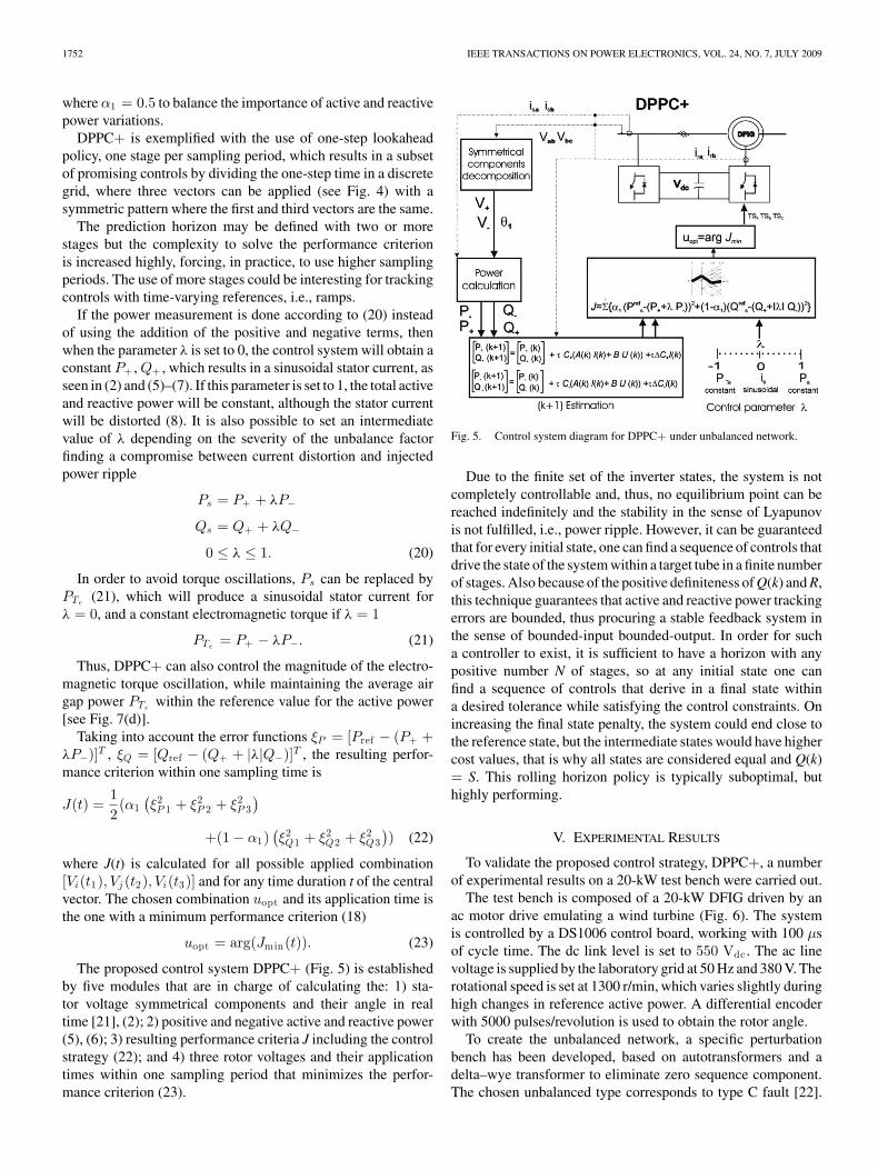
The proposed control system DPPC+ (Fig. 5) is establishedby five modules that are in charge of calculating the: 1) sta-tor voltage symmetrical components and their angle in realtime [21], (2); 2) positive and negative active and reactive power(5), (6); 3) resulting performance criteria J including the controlstrategy (22); and 4) three rotor voltages and their applicationtimes within one sampling period that minimizes the perfor-mance criterion (23).
Fig. 5. Control system diagram for DPPC+ under unbalanced network.
Due to the finite set of the inverter states, the system is notcompletely controllable and, thus, no equilibrium point can bereached indefinitely and the stability in the sense of Lyapunovis not fulfilled, i.e., power ripple. However, it can be guaranteedthat for every initial state, one can find a sequence of controls thatdrive the state of the system within a target tube in a finite numberof stages. Also because of the positive definiteness of Q(k) and R,this technique guarantees that active and reactive power trackingerrors are bounded, thus procuring a stable feedback system inthe sense of bounded-input bounded-output. In order for sucha controller to exist, it is sufficient to have a horizon with anypositive number N of stages, so at any initial state one canfind a sequence of controls that derive in a final state withina desired tolerance while satisfying the control constraints. Onincreasing the final state penalty, the system could end close tothe reference state, but the intermediate states would have highercost values, that is why all states are considered equal and Q(k)= S. This rolling horizon policy is typically suboptimal, buthighly performing.
V. EXPERIMENTAL RESULTS
To validate the proposed control strategy, DPPC+, a numberof experimental results on a 20-kW test bench were carried out.
The test bench is composed of a 20-kW DFIG driven by anac motor drive emulating a wind turbine (Fig. 6). The systemis controlled by a DS1006 control board, working with 100 µsof cycle time. The dc link level is set to 550 Vdc . The ac linevoltage is supplied by the laboratory grid at 50 Hz and 380 V. Therotational speed is set at 1300 r/min, which varies slightly duringhigh changes in reference active power. A differential encoderwith 5000 pulses/revolution is used to obtain the rotor angle.
To create the unbalanced network, a specific perturbationbench has been developed, based on autotransformers and adelta–wye transformer to eliminate zero sequence component.The chosen unbalanced type corresponds to type C fault [22].
SANTOS-MARTIN et al.: PROVIDING RIDE-THROUGH CAPABILITY TO A DFIG UNDER UNBALANCED VOLTAGE DIPS 1753
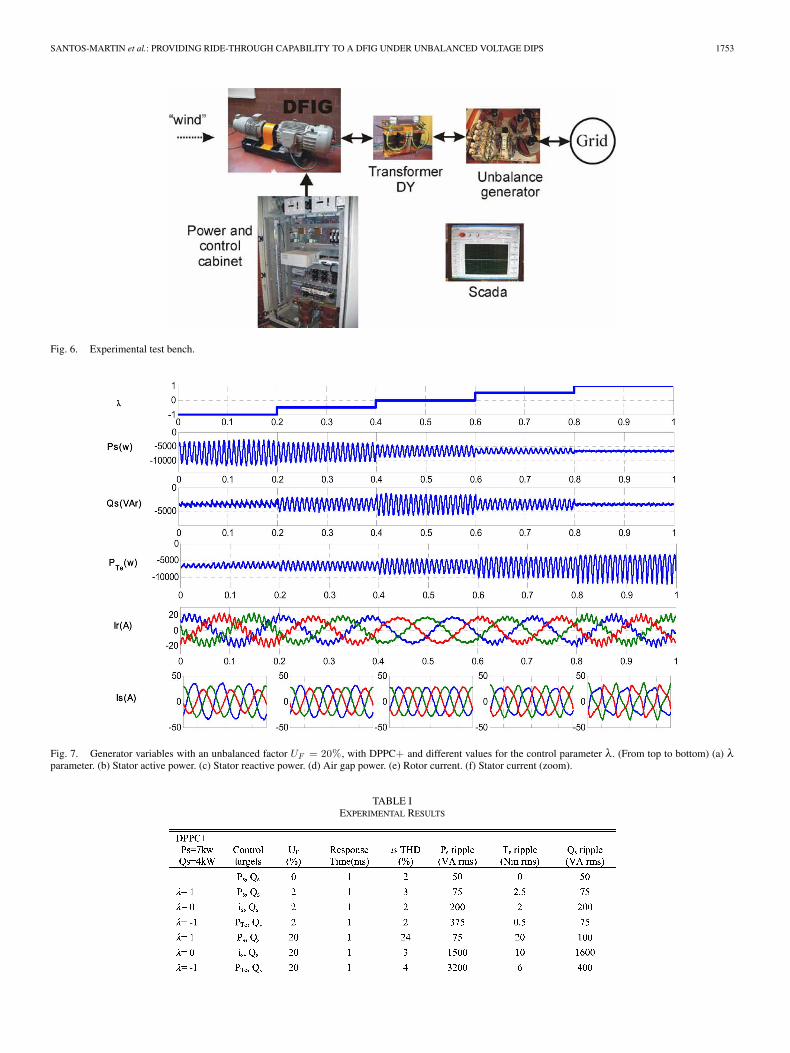
Fig. 6. Experimental test bench.
Fig. 7. Generator variables with an unbalanced factor UF = 20%, with DPPC+ and different values for the control parameter λ. (From top to bottom) (a) λparameter. (b) Stator active power. (c) Stator reactive power. (d) Air gap power. (e) Rotor current. (f) Stator current (zoom).
TABLE IEXPERIMENTAL RESULTS
1754 IEEE TRANSACTIONS ON POWER ELECTRONICS, VOL. 24, NO. 7, JULY 2009
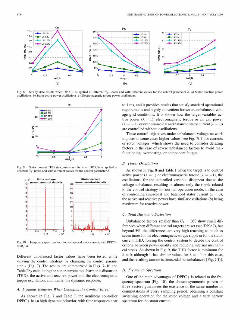
Fig. 8. Steady-state results when DPPC+ is applied at different UF levels and with different values for the control parameter λ. a) Stator reactive poweroscillations. b) Stator active power oscillations. c) Electromagnetic torque power oscillations.
Fig. 9. Stator current THD steady-state results when DPPC+ is applied atdifferent UF levels and with different values for the control parameter λ.
Fig. 10. Frequency spectrum for rotor voltage and stator current, with DPPC+(100 µs).
Different unbalanced factor values have been tested whilevarying the control strategy by changing the control param-eter λ (Fig. 7). The results are summarized in Figs. 7–10 andTable I by calculating the stator current total harmonic distortion(THD), the active and reactive power and the electromagnetictorque oscillation, and finally, the dynamic response.
A. Dynamic Behavior When Changing the Control Target
As shown in Fig. 7 and Table I, the nonlinear controllerDPPC+ has a high dynamic behavior, with time responses near
to 1 ms, and it provides results that satisfy standard operationalrequirements and highly convenient for severe unbalanced volt-age grid conditions. It is shown how the target variables ac-tive power (λ = 1), electromagnetic torque or air gap power(λ = −1), or even sinusoidal and balanced stator current (λ = 0)are controlled without oscillations.
These control objectives under unbalanced voltage networkimposes in some cases higher values [see Fig. 7(f)] for currentsor rotor voltages, which shows the need to consider deratingfactors in the case of severe unbalanced factors to avoid mal-functioning, overheating, or component fatigue.
B. Power Oscillations
As shown in Fig. 8 and Table I when the target is to controlactive power (λ = 1) or electromagnetic torque (λ = −1), theoscillations, for the controlled variable, disappear due to thevoltage unbalance, resulting in almost only the ripple relatedto the control strategy for normal operation mode. In the caseof controlling sinusoidal and balanced stator current (λ = 0),the active and reactive power have similar oscillations (8) beingmaximum for reactive power.
C. Total Harmonic Distortion
Unbalanced factors smaller than UF = 3% show small dif-ferences when different control targets are set (see Table I), butbeyond 5%, the differences are very high reaching as much asseven times for the electromagnetic torque ripple or for the statorcurrent THD, forcing the control system to decide the controlcriteria between power quality and reducing internal mechani-cal stress. As shown in Fig. 9, the THD factor is minimum forλ = 0, although it has similar values for λ = −1 in this case,and the resulting current is sinusoidal but unbalanced [Fig. 7(f)].
D. Frequency Spectrum
One of the main advantages of DPPC+ is related to the fre-quency spectrum (Fig. 10); the chosen symmetric pattern ofthree vectors guarantees the existence of the same number ofcommutations at every sampling period, obtaining a constantswitching operation for the rotor voltage and a very narrowspectrum for the stator current.
SANTOS-MARTIN et al.: PROVIDING RIDE-THROUGH CAPABILITY TO A DFIG UNDER UNBALANCED VOLTAGE DIPS 1755
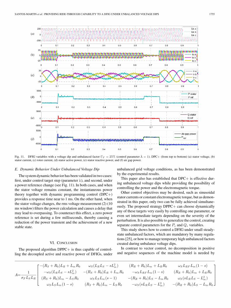
Fig. 11. DFIG variables with a voltage dip and unbalanced factor UF = 25% (control parameter λ = 1). DPC+ (from top to bottom) (a) stator voltage, (b)stator current, (c) rotor current, (d) stator active power, (e) stator reactive power, and (f) air gap power.
E. Dynamic Behavior Under Unbalanced Voltage Dip
The system dynamic behavior has been validated in two cases:first, under control target step (parameter λ), and second, undera power reference change (see Fig. 11). In both cases, and whenthe stator voltage remains constant, the instantaneous powertheory together with dynamic programming control (DPC+)provides a response time near to 1 ms. On the other hand, whenthe stator voltage changes, the rms voltage measurement (2) (10ms window) filters the power calculation and causes a delay thatmay lead to overpassing. To counteract this effect, a zero powerreference is set during a few milliseconds, thereby causing areduction of the power transient and the achievement of a newstable state.
VI. CONCLUSION
The proposed algorithm DPPC+ is thus capable of control-ling the decoupled active and reactive power of DFIGs, under
unbalanced grid voltage conditions, as has been demonstratedby the experimental results.
This paper also has established that DPC+ is effective dur-ing unbalanced voltage dips while providing the possibility ofcontrolling the power and the electromagnetic torque.
Other control objectives may be desired, such as sinusoidalstator currents or constant electromagnetic torque, but as demon-strated in this paper, only two can be fully achieved simultane-ously. The proposed strategy DPPC+ can choose dynamicallyany of these targets very easily by controlling one parameter, oreven set intermediate targets depending on the severity of theperturbation. It is also possible to generalize the control, creatingseparate control parameters for the Ps and Qs variables.
This study shows how to control a DFIG under small steady-state unbalanced factors, which are mandatory by many regula-tions [25], or how to manage temporary high unbalanced factorscreated during unbalance voltage dips.
In contrast to vector control, no decomposition in positiveand negative sequences of the machine model is needed by
A=1
σF LS LR
−(RS + R0)LR + Lm R0 ωS (LRLS − sL2
m ) (RR + R0)Lm + LRR0 ωS LRF Lm (1 − s)
−ωS (LRLS − sL2m ) −(RS + R0)LR + Lm R0 −ωS LRF Lm (1 − s) (RR + R0)Lm + LRR0
(RS + R0)Lm − LS R0 ωS LS Lm (s − 1) −(RR + R0)LS − Lm R0 ωS (sLRLS − L2m )
ωS LS Lm (1 − s) (RS + R0)Lm − LS R0 −ωS (sLRLS − L2m ) −(RR + R0)LS − Lm R0
1756 IEEE TRANSACTIONS ON POWER ELECTRONICS, VOL. 24, NO. 7, JULY 2009
DPPC+ while controlling the DFIG under unbalanced gridvoltage.
DPPC+ is also a very robust control system for a wide rangeof unbalance factor values with high dynamics at nearly constantcommutation frequencies (see Fig. 10).
All these factors make DPPC+ an attractive proposition thatensures a high-performance control of drives for DFIG gen-erators, among other types of generators used in wind energyapplications.
APPENDIX
The matrix definitions can be given as, A, as shown at thebottom of the previous page, where Rs , Rr , and R0 are the stator,rotor, and serial iron resistance, respectively, Ls and LR are thestator and rotor inductance, Lm is the magnetizing inductance,ωs is the synchronous speed, s is the slip, and σF is the leakagefactor
B =1
σF LS LR
LRF 0 −Lm 0
0 LRF 0 −Lm
−Lm 0 LS 0
0 −Lm 0 LS
,
C+ =32
[u+
sd u+sq 0 0
u+sq −u+
sd 0 0
]
C− =32
[u−
sd u−sq 0 0
u−sq −u−
sd 0 0
]
where u+sd and u+
sq are the projections of the positive componentus
+ over the total stator voltage us = us+ + us
−, and u−sd and
u−sq are the projections of the negative component us
−.
REFERENCES
[1] I. Takahashi and Y. Ohmori, “High-performance direct torque control ofan induction motor,” IEEE Trans. Ind. Appl., vol. 25, no. 2, pp. 257–264,Mar./Apr. 1989.
[2] M. Depenbrock, “Direct self-control (DSC) of inverter-fed induction ma-chine,” IEEE Trans. Ind. Appl. Power Electron., vol. 3, no. 4, pp. 420–429,Oct. 1988.
[3] T. Onishi, “Three phase PWM converter/inverter by means of instanta-neous active and reactive power control,” in Proc. Int. Conf. Ind. Electron.Control Instrum. (IECON 1991), vol. 1, pp. 819–824.
[4] R. Bellman and S. Dreyfus, Applied Dynamic Programming. Princeton,NJ: Princeton Univ. Press, 1962.
[5] M. H. J. Bollen, Understanding Power Quality Problems, Voltage Sagsand Interruptions. New York: IEEE Press, 2000.
[6] E. Muljadi, T. Batan, D. Yildirim, and C. P. Butterfield, “Understandingthe unbalanced-voltage problem in wind turbine generation,” in Proc. Ind.Appl. Conf., 1999, vol. 2, pp. 1359–1365.
[7] W. H. Kersting and W. H. Phillips, “Phase frame analysis of the effectsof voltage unbalance on induction machines,” IEEE Trans. Ind. Appl.,vol. 33, no. 2, pp. 415–420, Mar./Apr. 1997.
[8] J. Faiz and H. Ebrahimpour, “Precise derating of three-phase inductionmotors with unbalanced voltages,” in Proc. Ind. Appl. Conf., 2005, vol. 1,pp. 485–491.
[9] K. Lee, M. Jahns, W. E. Berkopec, and T. A. Lipo, “Closed-form analysisof adjustable-speed drive performance under input-voltage unbalance andsag conditions,” IEEE Trans. Ind. Appl., vol. 42, no. 3, pp. 733–741,May/Jun. 2006.
[10] J. Jang, Y. Kim, and D. Lee, “Active and reactive power control of DFIGfor wind energy conversion under unbalanced grid voltage,” in Proc. IEEE5th Annu. Power Electron. Motion Control Conf., Aug.14–16, 2006, vol. 3,pp. 1–5.
[11] M. H. J. Bollen and R. A. A. de Graaff, “Behavior of AC and DC drivesduring voltage sags with phase-angle jump and three-phase unbalance,” inProc. IEEE Power Eng. Soc. Winter Meeting, Feb., 1999, vol. 2, pp. 1225–1230.
[12] R. Pena, R. Cardenas, E. Escobar, J. Clare, and P. Wheeler, “Controlsystem for unbalanced operation of stand-alone double fed induction gen-erators,” IEEE Trans. Energy Convers., vol. 22, no. 2, pp. 544–545, Jun.2007.
[13] L. Xu and Y. Wang, “Dynamic modelling and control of DFIG-basedwind turbines under unbalanced network conditions,” IEEE Trans. PowerElectron., vol. 22, no. 1, pp. 314–323, Feb. 2007.
[14] T Brekken and N. Mohan, “Control of a doubly fed induction wind gen-erator under unbalanced grid voltage conditions,” IEEE Trans. EnergyConvers., vol. 22, no. 1, pp. 129–135, Mar. 2007.
[15] M. R. Rathi, P. P. Jose, and N. Mohan, “A novel H∞ based controller forwind turbine applications operating under unbalanced voltage conditions,”in Proc. 13th Intell. Syst. Appl. Power Syst. Conf., Nov. 2005, vol. 2,pp. 355–360.
[16] S. Seman, J. Niiranen, and A. Arkkio, “Ride-through analysis of doublyfed induction wind-power generator under unsymmetrical network distur-bance,” IEEE Trans. Power Syst., vol. 21, no. 4, pp. 1782–1789, Nov.2006.
[17] G. C. Paap, “Symmetrical components in the time domain and their appli-cation to power network calculations,” IEEE Trans. Power Syst., vol. 15,no. 2, pp. 522–528, May 2000.
[18] P. Pillary and M. Manyage, “Definitions of voltage unbalance,” IEEEPower Eng. Rev., vol. 21, no. 5, pp. 49–51, May 2001.
[19] M. H. J. Bollen, “Definitions of voltage unbalance,” IEEE Power Eng.Rev., vol. 22, no. 11, pp. 49–50, Nov. 2002.
[20] J. Arrillaga, M. H. J. Bollen, and N. R. Watson, “Power quality followingderegulation,” Proc. IEEE, vol. 88, no. 2, pp. 246–261, Nov. 2006.
[21] J. A. L. Ghijselen and A. P. M. Van de Bossche, “Exact voltage unbal-ance assessment without phase measurements,” IEEE Trans. Power Syst.,vol. 20, no. 1, pp. 519–520, Feb. 2005.
[22] M. H. J. Bollen, “Algorithms for characterizing measured three-phaseunbalanced voltage dips,” IEEE Trans. Power Del., vol. 18, no. 3, pp. 937–944, Jul. 2003.
[23] G. Zhang and Z. Xu, “A new real-time negative and positive sequencecomponents detecting method based on space vector,” in Proc. IEEEPower Eng. Soc. Winter Meeting, Feb. 2001, vol. 1, pp. 275–280.
[24] D. G. Holmes and T. A. Lipo, Pulse Width Modulation for Power Convert-ers: Principles and Practice (IEEE Press Series on Power Engineering).New York: Wiley/IEEE Press, 2002.
[25] A. L. F. Filho, M. A. Olivera, M. G. Pinto, A computational tool to analyze,quantify and classify imbalance in electrical power systems.
[26] L. Xu, “Coordinated control of DFIG’s rotor and grid side convertersduring network unbalance,” IEEE Trans. Power Electron., vol. 23, no. 3,pp. 1041–1049, May 2008.
[27] P. S. Flannery and G. Venkataramanan, “A fault tolerant doubly fed in-duction generator wind turbine using a parallel grid side rectifier andseries grid side converter,” IEEE Trans. Power Electron., vol. 23, no. 3,pp. 1126–1135, May 2008.
[28] D. Santos-Martin, J. L. Rodriguez-Amenedo, and S. Arnalte, “Directpower control applied to doubly fed induction generator under unbal-anced grid voltage conditions,” IEEE Trans. Power Electron., vol. 23,no. 5, pp. 2328–2336, Sep. 2008.
[29] D. Santos-Martin, J. L. Rodriguez-Amenedo, and S. Arnalte, “Dynamicprogramming power control for doubly fed induction generators,” IEEETrans. Power Electron., vol. 23, no. 5, pp. 2337–2345, Sep. 2008.
David Santos-Martin received the B.Sc. degree inelectrical and electronic engineering from the E.T.S.Industrial Engineering of Madrid (ETSII), TechnicalUniversity of Madrid (UPM), Madrid, Spain, in 1997,the M.Sc. degree in control engineering from theEcole Superieure d’Electricite (SUPELEC), Paris,France, and the Ph.D. degree from the UniversityCarlos III of Madrid, Madrid.
He is currently an Assistant Lecturer in the Depart-ment of Electrical Engineering, University Carlos IIIof Madrid. From 2001 to 2007, he was with Iberdrola.
From 2000 to 2001, he was with Ecotecnia-Alsthom. His current research in-terests include power electronics, and application of power electronics to powersystems and advanced control techniques applied to renewable energy.

SANTOS-MARTIN et al.: PROVIDING RIDE-THROUGH CAPABILITY TO A DFIG UNDER UNBALANCED VOLTAGE DIPS 1757
Jose Luis Rodriguez-Amenedo, photograph and biography not available at thetime of publication.
Santiago Arnaltes (A’02–M’02) received the Ph.D.degree in electrical engineering from the PolytechnicUniversity of Madrid, Madrid, Spain, in 1993.
Since 1997, he has been an Associate Professor inthe Department of Electrical Engineering, UniversityCarlos III of Madrid, Madrid. His current researchinterests include grid integration of wind energy andcontrol of electrical drives and flexible ac trans-mission system (FACTS), mainly for wind energyapplications.