Embed Size (px)
Citation preview

12d Model v7 interface to Leica 1200 instruments
June 2005 Page 1
User,
These notes describe the interfacing of 12d version 7 with the Leica 1200 series surveying instruments.
The processes of transferring the files to the CF card both via Leica Geo Office and direct to the survey
instrument are described
The following assumptions are made
1) Software versions
a. 12d………………………………………..version 7.0C1e
b. 1200 simulator……………………version 2.12
c. Leica Geo Office………………..version 2,0,0,0 Build 5028
2) Total station preloaded with the following files supplied by CR Kennedy
a. 12d format file
b. Std config set
c. Sample 12d code list
Upload options include
1) GSI points p 2 - 8
2) Ascii file p 9 - 18
3) Dxf file p 19 - 23
4) DXF tin p 24 - 28
5) XML / Data Base tin p 29
6) XML / Data Base Road Strings p 30 - 31
Download options include
7) Creating / Downloading 12d field file p 32 - 33

12d Model v7 interface to Leica 1200 instruments
Page 2 June 2005
1 GSI points
1.1 Create GSI upload in 12d
Select option Survey=>Upload=>Create Points upload file
or select option Survey=>Leica=>GSI=>Points
Select Leica GSI 16 for instrument choice
Select relevant data source
Select Get Point Range to set start and end
point numbers
Type in file name to create
Select Write File

12d Model v7 interface to Leica 1200 instruments
June 2005 Page 3
1.2 Convert GSI file to database file using Leica Geo Office
Run Leica Geo Office
Select Management tab
Select Project icon
Right click on Project then select
New…
Type in Project name then select OK
Select Import=>Raw data

12d Model v7 interface to Leica 1200 instruments
Page 4 June 2005
Select the newly created gsi file from the 12d working folder then select Import
Select Assign

12d Model v7 interface to Leica 1200 instruments
June 2005 Page 5
Select Close
The coordinates are shown. Select View/Edit tab to see a map of the points

12d Model v7 interface to Leica 1200 instruments
Page 6 June 2005
Close the project
Right click on Project name then select Send to=>PC/CF-Card=>for System 1200
This sends the file to the card to be loaded into the instrument

12d Model v7 interface to Leica 1200 instruments
June 2005 Page 7
1.3 Converting GSI file on board instrument
Copy the newly created GSI file from the 12d working folder to the GSI folder on the
CF card
On the 1200 select 4 to go to Convert menu
Select 2 to import GSI data to job

12d Model v7 interface to Leica 1200 instruments
Page 8 June 2005
Select Import type GSI Data
Select GSI file
Select existing job or create new job
Select F1 to import
Select F4 to finish import
Select F8 to view the uploaded file

12d Model v7 interface to Leica 1200 instruments
June 2005 Page 9
2 Ascii file of coordinates
2.1 Create ascii file in 12d
Select option File I/O=>Data output=>xyz s pt_no
Select relevant data source
Set Output mode to Delimiter
Set the column numbers as per the panel
Change the delimiter to comma ","
Type in the file name
Select Write

12d Model v7 interface to Leica 1200 instruments
Page 10 June 2005
2.2 Convert XYZ file to database file using Leica Geo Office
Run Leica Geo Office
Select Management tab
Select Project icon
Right click on Project then select
New…
Type in Project name then select OK
Select Import=>Raw data

12d Model v7 interface to Leica 1200 instruments
June 2005 Page 11
Select the newly created ascii file from the 12d working folder then select Import
Select Next

12d Model v7 interface to Leica 1200 instruments
Page 12 June 2005
Select Next
Right click on 1st column tab and select Point Id
Right click on 2nd column tab and select Coordinates=>Easting

12d Model v7 interface to Leica 1200 instruments
June 2005 Page 13
Right click on 3rd column tab and select Coordinates=>Northing
Right click on 4th column tab and select Coordinates=>Orth. Height
Right click on 5th column tab and select Code group
Select Next
Type in template name for any future conversions then select Finish

12d Model v7 interface to Leica 1200 instruments
Page 14 June 2005
Select Assign then Close
Close the project

12d Model v7 interface to Leica 1200 instruments
June 2005 Page 15
Right click on Project name then select Send to=>PC/CF-Card=>for System 1200
This sends the file to the card to be loaded into the instrument

12d Model v7 interface to Leica 1200 instruments
Page 16 June 2005
2.3 Converting Ascii file on board instrument
Copy the newly created ASCII (*.dat) file from the 12d working folder to the Data
folder on the CF card
On the 1200 select 4 to go to Convert menu
Select 2 to import GSI data to job

12d Model v7 interface to Leica 1200 instruments
June 2005 Page 17
Select F8 to view the uploaded file

12d Model v7 interface to Leica 1200 instruments
Page 18 June 2005
Select F8 to view the uploaded file

12d Model v7 interface to Leica 1200 instruments
June 2005 Page 19
3 Dxf file of points / lines
3.1 Create dxf file in 12d
Select option File I/O=>Data output=>DWG/DXF
Select relevant data source
Select DXF format
Type in the file name
Set Dimension to 2d
Select Write

12d Model v7 interface to Leica 1200 instruments
Page 20 June 2005
3.2 Convert DXF file to database file using Leica Geo Office
Run Leica Geo Office
Select Tools tab
Selec Design to Field
Select New
Type in new job name
Change the Importer type to Points, Lines & Areas Importer
Select OK

12d Model v7 interface to Leica 1200 instruments
June 2005 Page 21
Change the Importer to DXF-Importer 1.0.0.13
Select Import
Select Next
Select the newly created dxf file from the 12d working folder then select Next
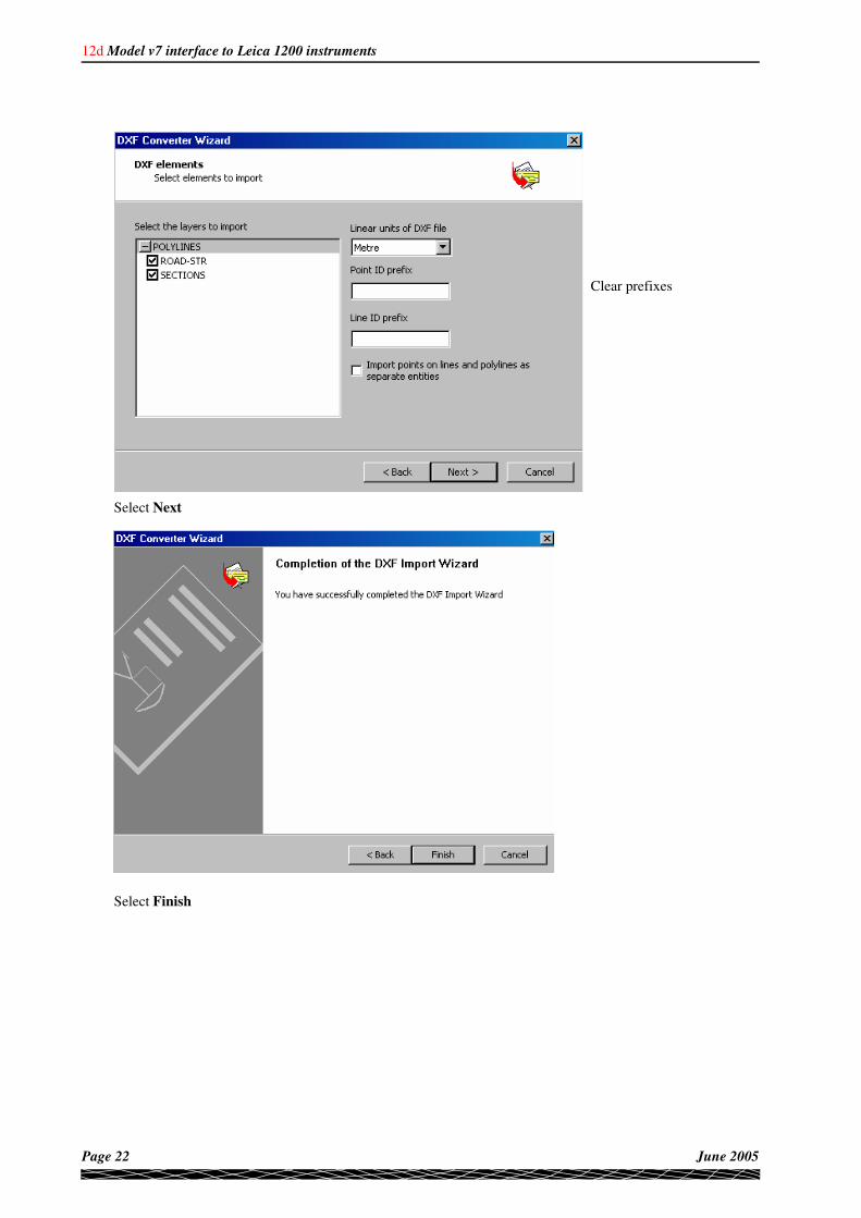
12d Model v7 interface to Leica 1200 instruments
Page 22 June 2005
Clear prefixes
Select Next
Select Finish

12d Model v7 interface to Leica 1200 instruments
June 2005 Page 23
Select Pack & Go!..
Select Close

12d Model v7 interface to Leica 1200 instruments
Page 24 June 2005
4 Dxf file of TIN
4.1 Create dxf file in 12d
Select option File I/O=>Data output=>DWG/DXF
Select relevant data source for TIN model
Select DXF format
Type in the file name
Set Dimension to 3d
Select Write

12d Model v7 interface to Leica 1200 instruments
June 2005 Page 25
4.2 Convert DXF TIN file to database file using Leica Geo Office
Run Leica Geo Office
Select Tools tab
Selec Design to Field
Select New
Type in new job name
Change the Importer type to DTM Importer
Select OK

12d Model v7 interface to Leica 1200 instruments
Page 26 June 2005
Change the Importer to DTM (DXF)-Importer 1.0.0.13
Select Import
Select the newly created dxf TIN file from the 12d working folder then select Next

12d Model v7 interface to Leica 1200 instruments
June 2005 Page 27
Select Next
Select Finish

12d Model v7 interface to Leica 1200 instruments
Page 28 June 2005
Select Pack & Go!..
Select Close

12d Model v7 interface to Leica 1200 instruments
June 2005 Page 29
5 XML file / Data Base of TIN
5.1 Create XML / Data base files in 12d
Select option Survey=>Leica=>1200=>Triangles
5.2 Copy the data base files to the cf card
Type in the Jobname
Tick the check box to create database files
Select tin
Pick Tin Polygon boundary
Select Write
Select Yes
Copy the newly created data base
files (examples on left) from the 12d
working folder to the DBX folder on
the CF card

12d Model v7 interface to Leica 1200 instruments
Page 30 June 2005
6 XML / Data Base road strings (single or multi layers)
6.1 Single layer
Turn on the relevant road strings to be used in the layer along with the alignment if the layer is the finished
surface
Select option Survey=>Leica=>1200=>Roads
Copy the data base files to the cf card
NOTES
1) Ensure that the alignment starts before the strings and finishes after the strings. If this is
not the case simply edit the alignment string and extend it.
2) Strings can not reverse back on themselves and must run in the same direction as the
alignment
3) If using data imported via Genio format ensure there is only one alignment string per
work area
Select the Simple tab
Type in the Job name
Tick the check box so that the database is created
Tick check box to put all stringlines in a layer
Select the Pick icon then select the alignment string
Tick the check box if alignment string is to be included
in level calculations
Select the model name for the road strings
Type in layer name for the strings.
This is the the name visible to the user in Road Runner
Select Write
Copy the newly created data base
files (examples on left) from the 12d
working folder to the DBX folder on
the CF card

12d Model v7 interface to Leica 1200 instruments
June 2005 Page 31
6.2 Multi layer
The following panel allows the user to create multiple work areas along with mulitple layers for each work
area
Select option Survey=>Leica=>1200=>Road
Copy the data base files to the cf card
NOTES
1) Ensure that the alignment starts before the strings and finishes after the strings. If this is
not the case simply edit the alignment string and extend it.
2) Strings can not reverse back on themselves and must run in the same direction as the
alignment
3) If using data imported via Genio format ensure there is only one alignment string per
work area
Select the Advanced tab
Type in Job name as per simple method
Fill in each row picking the alignment string, string line models and layer name for the paritcular work
area
Tick the check box if alignment string is to be included in level calculations
The Layer name is the the name visible to the user in Road Runner
Click in last cell (under column name Layer name 5) then press [Enter] key to create new row
The second and subsequent row are for multiple work areasClick on Alignment string pick icon
Select Write
Copy the newly created data base
files (examples on left) from the 12d
working folder to the DBX folder on
the CF card

12d Model v7 interface to Leica 1200 instruments
Page 32 June 2005
7 Creating Field file
The detail survey is converted to a 12d field file on board the survey instrument
Select 4 to convert
Select 1 to export
Select CF Card to export to
Select the job to convert
Select the format file 12D_TPS.FRT
Type in the field file name
Select F1 to continue

12d Model v7 interface to Leica 1200 instruments
June 2005 Page 33
Select F4 to finish
Copy the field file from the card to the working folder in 12d
Once the field file is copied to the working folder the file is reduced using option
Survey=>Create=>Field File
See reduction notes in the Getting Started for Surveying manual

12d Model v7 interface to Leica 1200 instruments
Page 34 June 2005