Embed Size (px)
DESCRIPTION
125/150 Lambretta D/LD Spare Parts Manual including electric starter models
Citation preview
r I
_
_ ~:--_______ ~_~ ________ $H"" · .... n_·· ... ,.";""'1;"''''"'H~''''t _-.... . ...... _ · .. "';.'1.;0 _~".b'"
't" ,,----------~---:--------'---..,;
.'
Iamlirl!lla 150d/ld/ld electric starter
125 Id derived
Spare Parts Catalogue
""" ..
t "
~~===================::===="" ===--=. c=-__ -,--~t .... j
, \
,
\ '.r-'
I amli rl! Ua 150 d lId lId electric starter
125 ld derived
Spare Parts Catalogue
I i -I INNOCENTI I .,
INDEX
OF
SECTION
transmission case
Crankshaft and piston
Clutch
Ge~r bQX CQmpon=nts Transmission lind rear l",de components
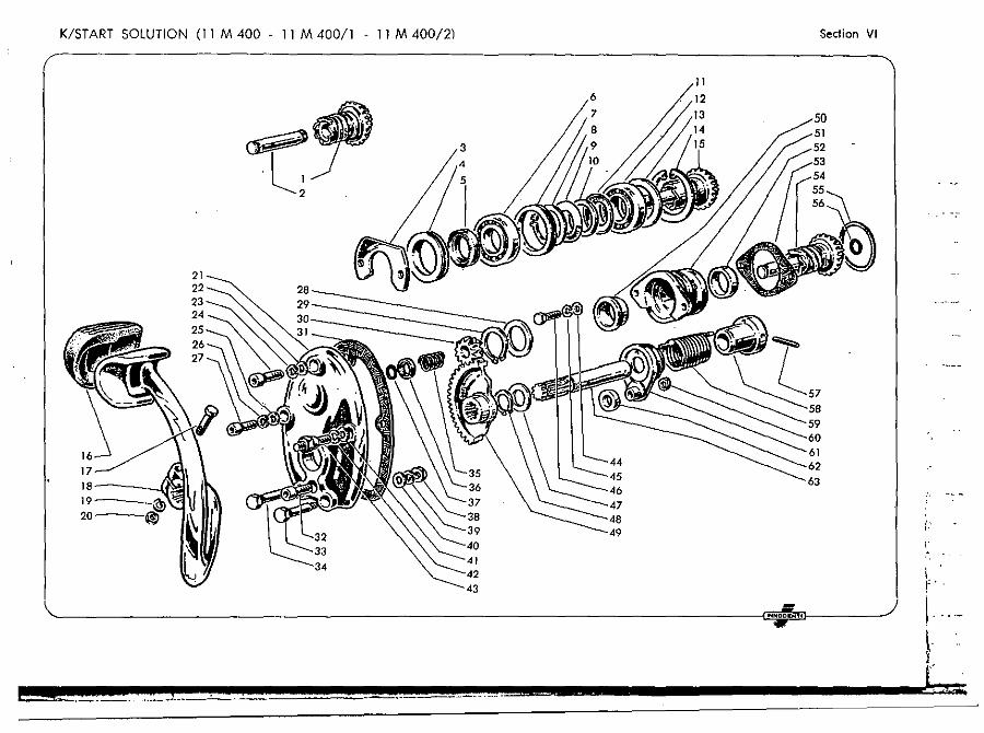
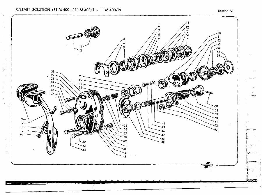
K/ start solution (11 M 400 -11 M 400/1 - 11 M 400/2)
K/st.rt solution (11 M 400/4
11
III
IV
v
VI
11 M 400/6) Vll ,
Epicyclical starter VIII :
Fuel" tank and carburettors IX
Exhaust silencers components
Cooling Xl
Frames and suspensions Xli . ~ "----
Handlebar and fork components X111 ;
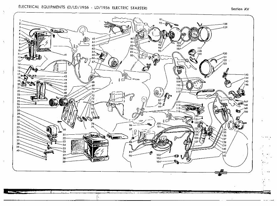
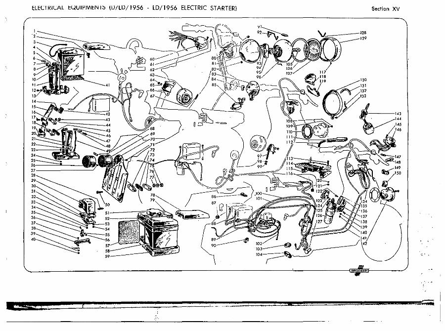
Wheels .nd ·brakes XIV Electrical equipments (D/lO 1956 -lO/1956 electric starter) XV i
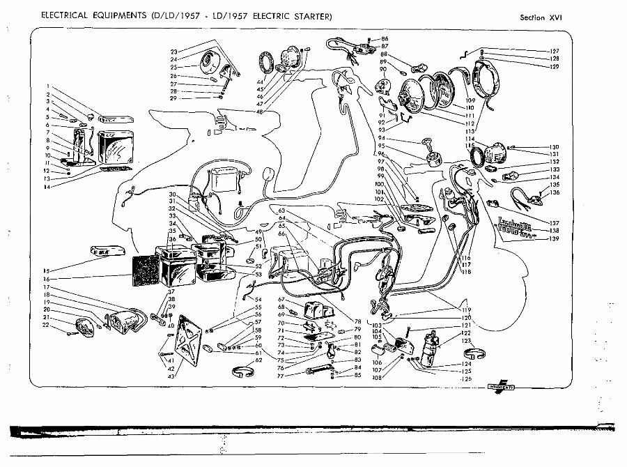
Electrical equipments (lD/1957 -lD/1957 electric starter) XVI'
Electric starter Flywheel magneto "Filso» and .. Marelli »
Panel and frame components
Cables and controls
Accessories
XVll
XV111 .
XIX ~ .. l-~ ..
XX ~ .. -
XX!: ~---to, .
INDEX ;.'
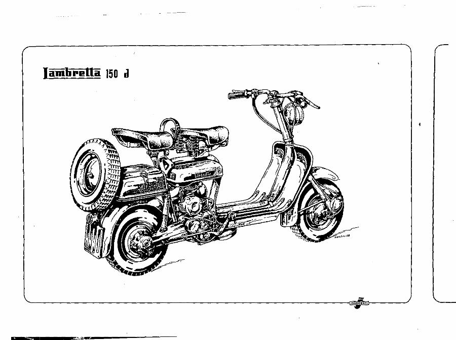
Iamlirl!lla 150 d
,""ceItHT'
-----"'"'-------
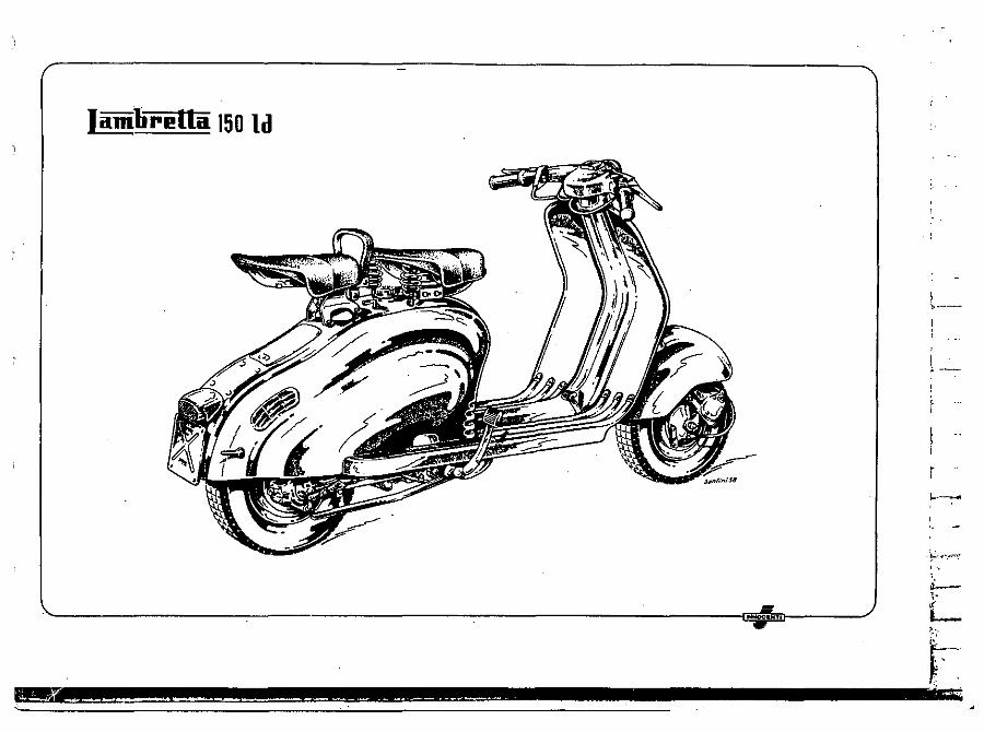
I i1mlirl!ltil 150 Id
, ! ~ ---.
I --
r ,--, . ,
'. ~
L
~ \1.,.1 ____ --~_ ...... ___ .. _. __ ~ __ ~'''_ .-
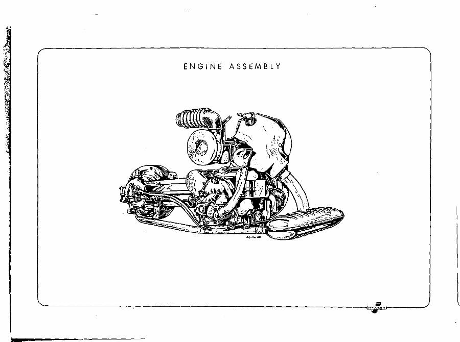
ENGINE ASSEMBLY
I , .... OCI: T.
I iiiiiti r I! [[a
WARNING!I!
This catalogue cancels and substitutes all previous publications concerning the following « lambretta » models,
150 O-LD - LD electric starter
125 LD· derived Productions 1955 - 1956 - 1957 - 1958
&
;. ---
l- ," •. '.
L \!'--
V [
Iamlirelta (
r------------------------------------------------------
Q
-
U
•• --"."\
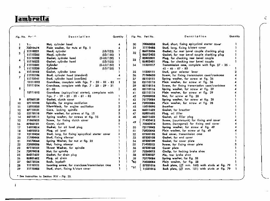
Fig. No. p;::,'" Description Quantity Fig. No. Pari No. Oescription "
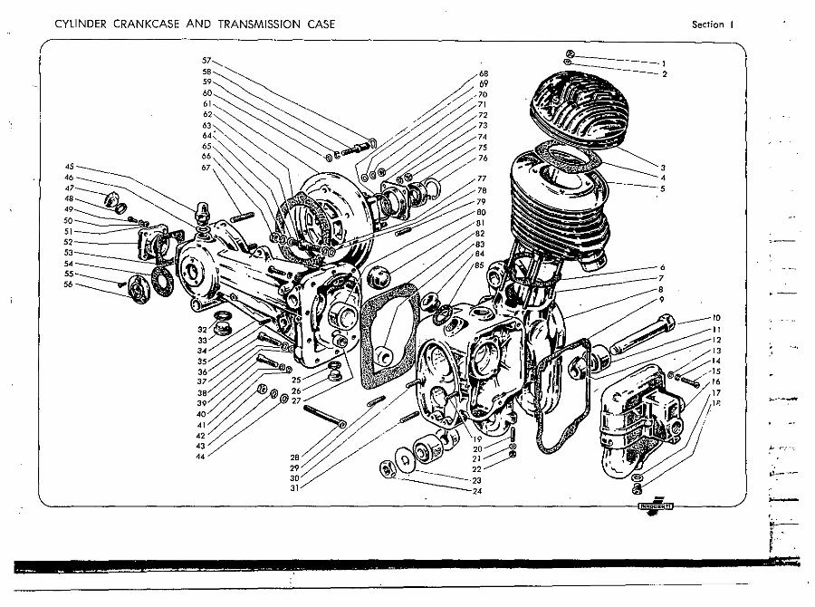
1 II. Nut, cylinder head 4 30 70060838 Stud, short, fjxing epicyclical sfllrter cover 2 730tW/4 Pl.in wa.h.r, for nuta at fig. 1 ,,31 11110486 Stud, long, fixing k/ttart cover
1
11110221 Hud, cylinder (lO/125) 1 32 i 86012836 G •• ket, for rear bevel couple checking plug 11110202 H ... ~ •. cylinder (LD/ISO) 1 86012432 Gaske., for rear bevel couple checking plug 11110201 Ga.ke., c:ylinder head (D.LD/ISO) 1 33 85802801 Plug, for checking re.r bevel couple
" 11110222 Glllht. cylinder head (LD/125) 1 85802401 Plug, for checking rear bevel couple 11110201 Cylinder (D.LD/ISO) 1 34 11331017 Transmillion ca •• , complete with figl. 27 - 35 -
5 11110220 Cylinder (LD/12S) I 45 - 4~ _ 67 - 80 1
3
6 11110103 Guket, cylinder base 1 35 11330111 Stud, gear selector lever 2
{ 11110106 Stud, cylinder head (standard) 4 36 71060620 Screw, for fixing transmission case/crankcase 4
7 11110141 Stud, cylinder head (oversize) 37 02110111 Spring wlISh.r, for screw at fig. 36 4
j 11111012 Cr.anckllS., complete with figs. 7 - 20 - 81 - 83 38 02110110 Plillin wlISh.r, for screw at fig. 36 4 11111014 Crillnckills., complete with figs. 7 - 20 - 29 - 31 39 02110114 Screw, for fixing transmission case/crankcase 4
8 l 81 - 83 40 02110116 Spring washer, for screw at fig. 39 4 12111012 CrillnckllSe (epicyclical starter), complete with 41 02110115 Plillin washer, for screw at fig. 39 4
figs. 7 - 19 - 20 • 30 - 81 - 83 1 42 72000008 NUl, for screw at "fig. 28 I 9 07060159 GillSket, clutch cover 1 43 73170084 Spring w.,her, for screw at fig" 28 1
10 07110150 Spindle, for engine oscillation I 44 7303008.4 PI.in willsher, for screw at fig. 28 11 150100~0 Silenl-block, for engine oscillation 2 45 15010090 Sr.iIIther 12 07110151 Cone, locking spindle Z 46 86011622 GlISk.t, for breather 13 02110110 pI.in wuher, for screws at fig. 15 5 47 85801602 Plug, oil filler 1 14 02110111 SP.ring wilsher, for screws at fig. 15 5 48 86011622 GiII,k.t, oil filler plug 1 15 71060625 Scr.w, for fixing clutch cover 5 { 71420412 Screw, (countersunk) for fixing end cover " 16 07060121 Cover, clutch 49 70360414 Screw, (hexagonal) for fixing end cover 4 17 14010014 Gaskel, for oil level plug 50 73170043 Spring willsh.r, for screw at fig. 49 4 18 14010013 Plug, oil level 1 51 73030043 Plillin wil.her, for screw at fig. 49 4 19 12110434 Stud. long, for fixing "epicyclical starter cover 1 52 07330105 End cover, transmission case 1 20 lH80444 Stud, fixing silencer 1 53 07330108 Gask.t. for end cover 1 21 73170064 Spring WlISh.r. for nut at fig. 22 1 54 07330109 GlISket. for cover plate 1 22 72030006 Nul, fixing silencer 1 55 71420512 Screw, for fixing cover plate 3 23 07110152 Thrust W.dler, for spindle I 56 07330103 Coyer pl.,. 1 24 72070011 Nut, for spindle t 57 73260012 Circlip, for locking brake shoe 25 86011622 Gilllket, for drain plug 1 58 07330337 Pin, rear brake sho.."! 26 85101602 Plug, oil drain 1 59 73170084 Spring willlh.r, for fig. 58 27 06110124 Bush, layshaft 1 ~O 73030084 PI.in w.sher, for fig. 58 28 11110121 Locillting screw, for cranckase/tranlmiSiion case 1 r 07331016 Buk pl.'e, (0 mm. 160) with sluds at fig. 79
'61 29 11110485 Stud, short, fixing k/start cover 1 111331016 Buk pl.te, (0 mm. 151) with stud, at fig. 79 ;
'-__ • __ S,_' __ ;"_'_"_U_"_;O_" __ 'O __ S_'_'_tio_" __ X_'_V __ -_F_;g_._2_._. ___________________________________________________________________________________________________ ~ '----
---------~------
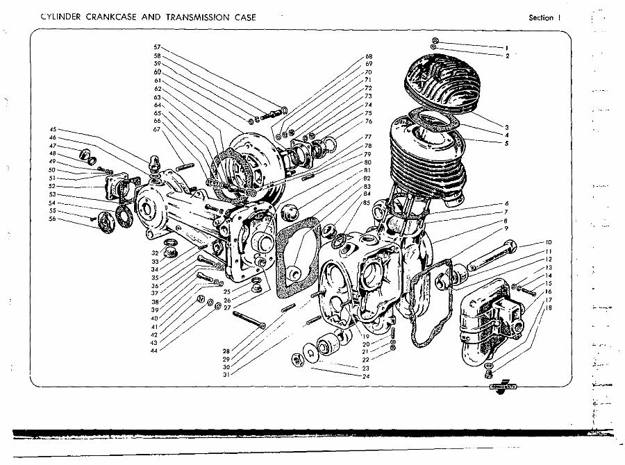
CYLINDER CRANKCASE AND TRANSMISSION CASE
I
A68 69 70 71
,/ 72 /' 73
74 75 76
3 4
>t----S
\L.~ __ -6
7
9
~--------------------------------------------
&2 _ E@!!!f ____ i
Section I
.!--- ..
~ ---,. ~.
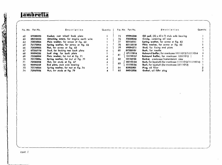
lamlirl!lla
Fig. No.
62 63 6, 65 66 67 68 69 70 71 72 73 74
conI. I
Pari No.
07330323 08010534 73010064 73170064 72030006 07330110 99094356 73030084 73170084 72030008 99094309 73170064 72060006
Description
Gilsk.t, rear wheel back plate Attilching Icrew, for engine earth wire Pltlin wilsh." for screw at fig. 63 Spring willh.r. for screw at fig. 63 Nut, for screw at fig. 63 Stud, for locking rear back plate S.al ring. for back plate Plain w,uher. for nut at fig. 71 Spring wtlsher, for nut at fig. 71 Nut, for studs at fig. 67 End prill., stub axle bearing Spring wilsh.r, for nut at fig. 74 Nut, for studs at fig. 79
QuaMily
, 1 , 4 4 1 , 4
Fig. No. Part No. Description Quantil,),
75 99094308 Oil su', (22 x 40 x 7) stub axle bearing 76 732500'0 Circlip, retaining oil seal 77 02110111 Spring washer, for screw al fig. 63 78 02110110 Plain wilsher, for screw at fig. 63 79 99094311 Stud, for fixing end plate 4 80 07330107 Bush, for needle 1
81 J 07111016 Rebound buHer, for crankcase 11111012/11111014 1 11110127 Rebound buffer, for crankcase 12111012 I
82 12110102 Gasket, crankcaseltransmission case
83 J 06110124 Bush, for layshafi (for crankcase 11111012/11111014) 1 1 11110126 Bush, for layshaft (for crankcase 12111012) 1
8' 85802801 Plug, oil filler 2 85 86012836 G.",k.t, oil filler plug 2
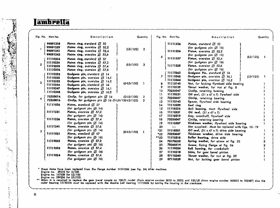
CYLINDER CRANKCA
45_~~~ 46_~~--..
:;~ 50 51--__
52-___ ,
N CASE SE AND TRANSMISSIO
65 66
21 22 J-_'-'-~_23 --'-----=24
Section
..... --,l.. ~'.-'
' ..
r-·
,. \
-r' o.
Fig. No. Part No.
! 99091208 99091239 99091241 99091242
{
11110324 11110334
2 11110335 11110336
f 11110323 11110332
3 11110333
l'1110346 11110347 11110348
4 { 732500).4 73250016
1"11026
11111231
11111236
11111241
S 11111021
11111022
11111023
1)11'024
Des cr i p t ion
Pislon ring. standard J2J S2 Pilton ,inll, oversize f2J 52,2 Piston ring, ovenize 0 52," Pi.,on rinl. oversize 0 52,6
Piston ring, standard to 57 Piston ring, oversize to 57,2 Piston ring, oversize 0 57,4 Piston ring, oversize 0 57,6
Gudgeon pin, standard 0 14 Gudgeon pin, oversize 0 14,1 Gudgeon pin, oversize 0 14,2 Gudgeon pin, standard 0 16 Gudgeon pin, oversize 0 16,1 Gudgeon pin, oversize 0 16,2
I I
Quantity
(Lo/l25) 2
(LOll SO) 3
(o-Lo/ISO)
Circlip, for gudgeon pin 0 14 (D-lD/150) Circlip, for gudgeon pin 0 16 (D-LO/150-W/125)
Piston, standard 0 57
2 2
(for gudgeon pin 0 14) Pislon, oversize 0 57,2 (for gudgeon pin 0 14) Pislon, oversize 0 57,4 (for gudgeon pin 0 14) Piston, oversize 0 57,6 (for gudgeon pin (O 14) Piston, standard 0 57 (for gudgeon pin 121 16) Piston, oversize 0 57,2 (for gudgeon pin' 0 16) Piston, oversize 21 57,4 (for gudgeon pin 21 16) Piston, oversize 0 57,6 {for gudgeon pin (21 16)
(o-Lo/ISO)
Fig. No. Part No.
II I 11306
11111326
6 11111321
11111328
(
11110362 7 11110363
11110364 8 lJll0140 9 11110139
10 73250047 II 11110351 12 73250047 13 11110142 14 lJ1l0309 15 11110326 16 11110351 17 11110310 18 73250047 19 11110301 20
'*21 11110351 '*22 73250041
'*'*23 11110316 24 73170053 2S 70360514 26 11110326 27 1111031_ 28 07110340 29 07110339
• These item. hive bun repiliced from th. filing. numb.r 11111356 (s •• fig. 34) If ler machine: Engine no. 39515 for 0/150 Engine. no. 167530 for LD/iSO Engine no. 289206 for LD/125 •
De,cription Quantity
Piston, standard 0 52 (for gudgeon pin 0 16) Pislon, oversize 0 52,2 (for gudgeon pin to 16) Piston, oversize 0 52,.4 (for gudgeon pin 0 16)
(LO/12S)
Piston, oversize 0 52,6 (for gudgeon pin (21 16) Gudgeon Pin, standard 0 16 Gudgeon pin, oversize 0 16,1 Gudgeon pin, oversize 0 16,2 I (Lo/12S)
Nut, for locking flywheel sjde bearing Thrust w •• her, for nut at fig. 8 Cirdip, retaining bearing oil s .. r, (31 x 47 x 7) flywheel side Cirdip, retaining bearing Sp.ur, flywheel side bearing S •• I ring 8.11 be.ri"9, main flywheel side Oil s .. I, (31 x 47 x 7) Key, woodruff, flywheel side Circlip, retaining bearing Thickne .. w .. her, flywheel side bearing Not .upplied - Must be replaced with fig •. Oil ... 1, (31 x 47 x 7) drive side bearing Thlckne •• w •• her, drive side bearing RoUer bearing, drive side Spring washer, for screw at fig. 25 Screw, fixing flange .t ltg. 34 8.1J b •• rin", for crankshaft Shim, for gear bevel pinion Thru.t w.sher, for nvl al fig. 29 Nut, for locking gear bevel pinion
13·19 1 I I 3 3 I I I I
.. When it is required to repillce the gear bev"r couple on lSO/0 mod,,/ (from engine number SOlO to 5853) and lSO/lD (from engine number 105003 to lOS.oCa7) also th" roller be.ring 11110316 mUll b. ,epllced wilh Ih. doubl. bell bearing 11110326 by boring the housing in the cranke ••• ,
II
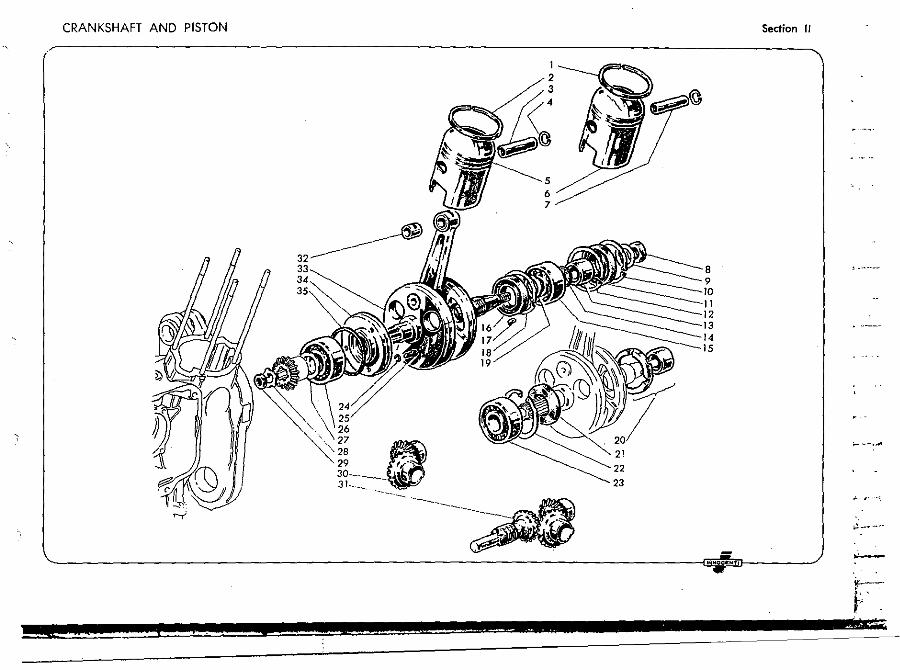
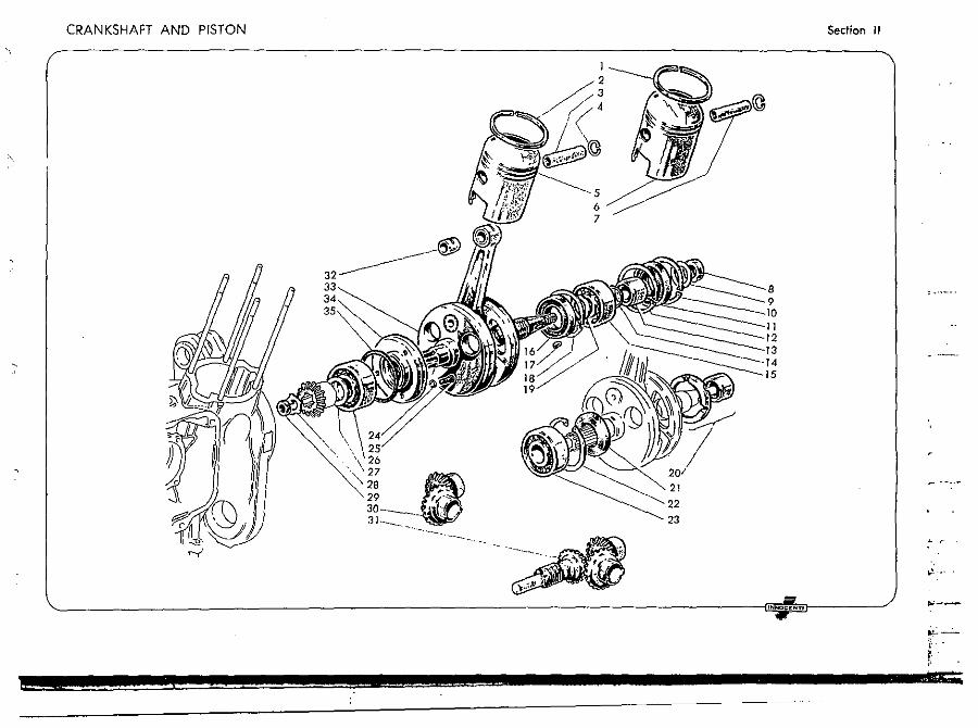
CRANKSHAFT AND PISTON
27
28 /I 29 ,.-30 . f,,·· ..
3'=:- . ._---,-- ----
1 2 3
5 6 7
-~
21
22 23
8 9
1 2
15
Sedion II
~ r···
;!-.~-'"
"---
.--. __ v__ r---~1_"I¥. -#< -- ~_.
Jamlirellil
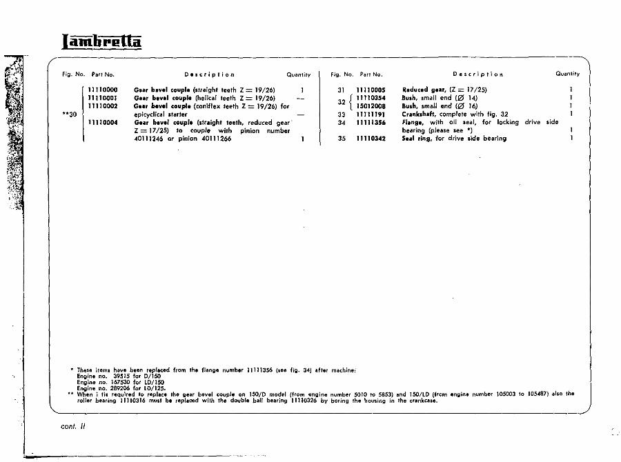
Fig. No. Part No.
"30 I 11 TlOOOO 11110001 11110002
1I1l0004
Description Quantity
GUt bevel couple (straight teeth Z = 19/26) Ge., bevel couple (helical teeth Z = 19/26) GUt bevel coupl. (caniflex teeth Z = 19/26) for epicyclical starter GUt bevel coupl. {straight teeth, reduced gear' Z = 1712S} to couple with pinion number 40111246 or pinion 40111266
Fig. No.
31
32 { 33 34
35
These items have been replaced from the flange number 11111356 (see fig. 34) after machine:
Pari No.
1111 0005 11110354 15012008 , 1111191 11111356
11110342
Description
Reduced gur, (Z = 17/25) BUlh, small end (0 14) Bush, small end ~0 16) Crankshaft, complete with fig. 32 FIling., with oil seal, for locking bearing (please see *) 5 •• 1 rins, for drive side bearing
Quantity
drive side
Engine no. 39515 for D/ISO Engine no. 167530 for LD/l50 Engine no. 289206 for LD/125. When i tis required to replace the gear bevel couple on 150/0 model (from engine number SOlO '0 5853) and lSO/LO (from engine number 105003 to 105<187) also the roller bearing 11110316 must be replaced with the double ball bearing 11110326 by boring the housing in the crankcase.
cont. II
CRANKSHAFT AND PISTON
32 ~
J 2 3 4
5 6 7
2. 22 23
Section II
INNOCENT'
~'. -0" •
~:-' ~.
r ;
\----------------------------------------------------------_/ III
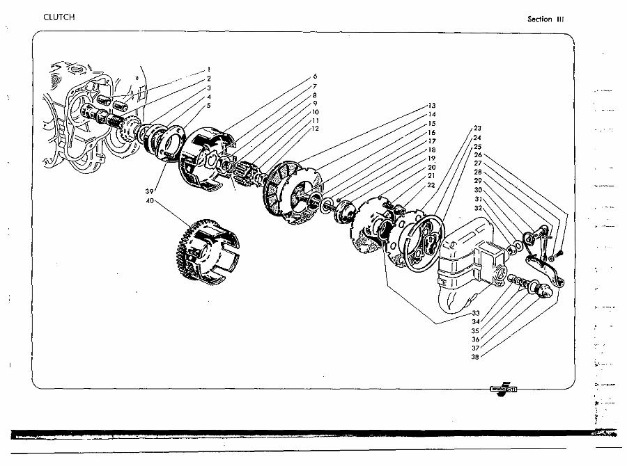
CLUTCH Section II/
___ - I 6 2 7 8 9 13 10 14 11 15
6
8 19
l 38
~'.-..
r;;;gz / >-~
'" :. .
4 22 ::s: hi!&.
IamlireUa
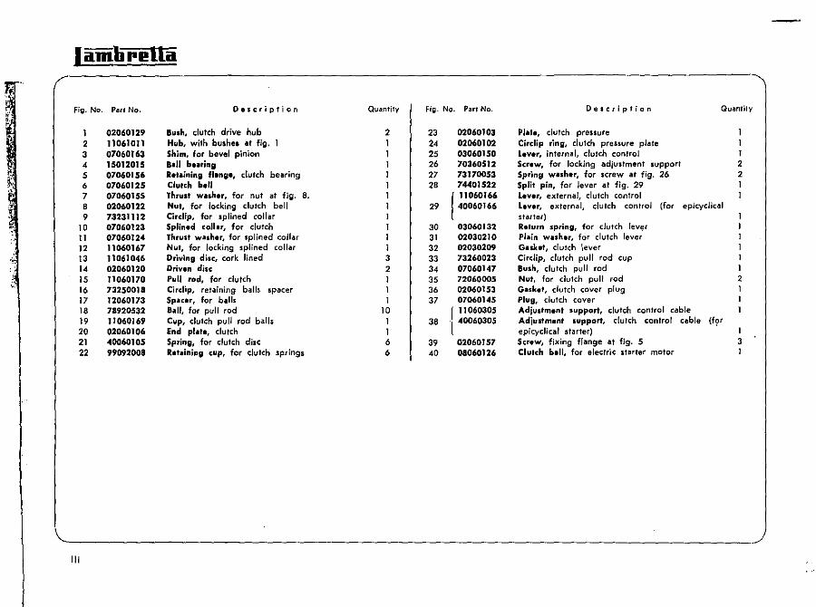
Fig. No. Pari N.:I. Description Quantity Fig. No. Part No. De,cripl;on
.~
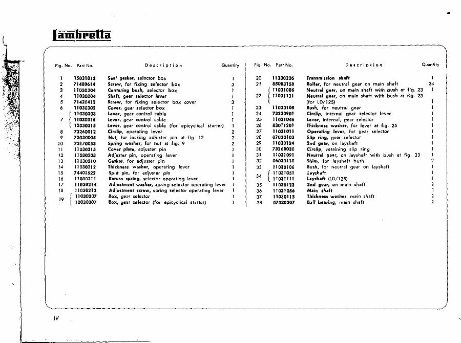
1 15031013 5 ... 1 g,ub" selector box 1 20 11330206 Trilnsmission shilf' 2 71480614 Screw, for fixing selector box 3 21 85003158 RoUer, for neutral gear on main shaft 24 3 11030304 Cent.ring bush, selector box 1 I 11031086 Neuf, .. 1 gur, on main shaft with bush at fig. 23 I 4 11030204 Shdt, gear selector lever I 22 11031131 Neutral sur, on main shaft with bush at fjg. 23 5 71420412 Screw, for fixing selector box cover 3 (for lD/125) 6 11030302 Cover, gear selector box I 23 11030108 Sush, for neutral gear
I J 1030303 Lever, gear control cable I 24 73230901 Circiip, infernal gear selector lever 7 11030315 Lever, gear control cable I 25 11031046 Leve" internal, gear selector
12030315 Lever, gear control cable (for epicyclical starter) 1 26 830"201 Thickness w.sher, for lever at fjg. 25 I 8 73260012 Circlip, operating lever 2 27 11031011 Operilting lever, for gear selector 1 9 72030005 Nut, for locking ad;uster pin at fig. 12 2 28 07030103 Slip ring, gear selector 1
10 73170053 Spring wuher, for nut at fig. 9 2 29 11030124 2nd gear, on layshaft 1 II 11030215 Cover pJilte, adjuster pin I 30 73260030 Circlip, retaining slip ring I 12 11030208 Adjuster pin, operating lever 31 11031091 Neutrill geilr, on layshaft with bush at fig. 33 1 13 11030210 Gasket, for adjuster pin 32 06030110 Shim, for lays haft bush 2 14 11030212 Thickness wilsher, operating lever 33 11 0301 06 Bush, for neutral gear on layshaft 15 74401522 Split pin, for ad;usler pin
34 f 11031051 hyshilft 16 11030211 Return spring, selector operating lever 1 110311 " lilyshaft (lD/125) 17 11030214 Adjustment w.sher, spring selector operating lever 35 11030123 2nd gear, on main shaft
" 11030213 Adjustment screw, spring selector operating lever 36 Tl031056 Main shaft
19 { 11030307 Box, gear selector 37 11030115 Thickness washer, main shaft 12030307 Box, gear seledor (for epicyclical starter) 38 07330207 Ball bearing, main shaft
IV
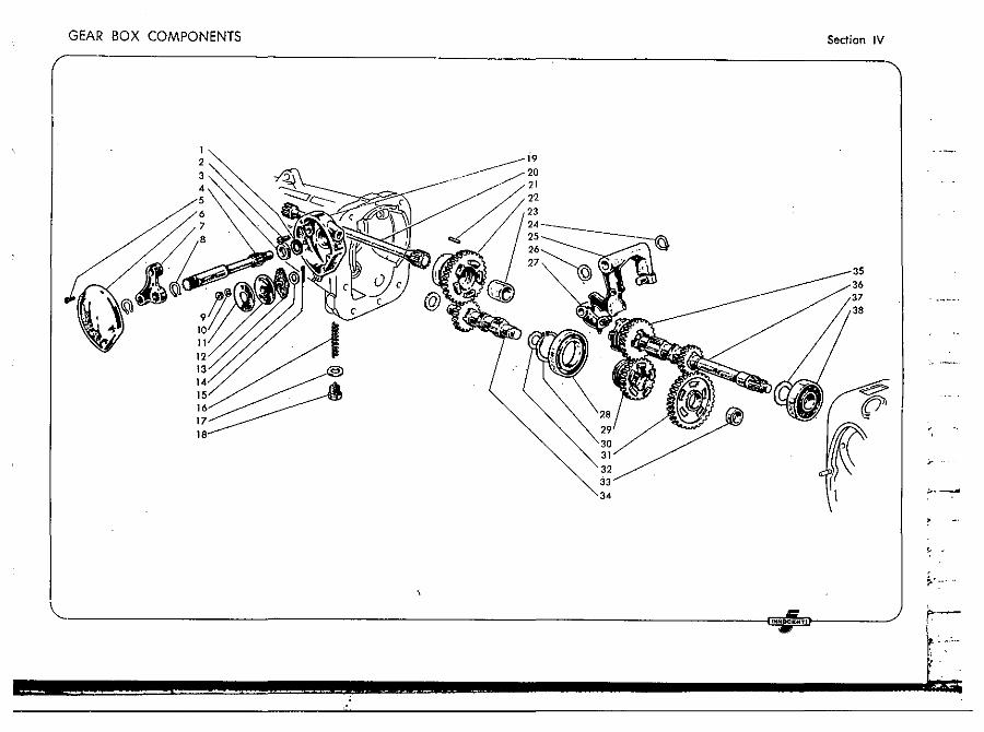
GEAR BOX COMPONENTS Section IV
;, ..
, ,
~'-....
INNOCENTI
r I amli rl! Itil
Fig. Ne. Part Ne. Description
v
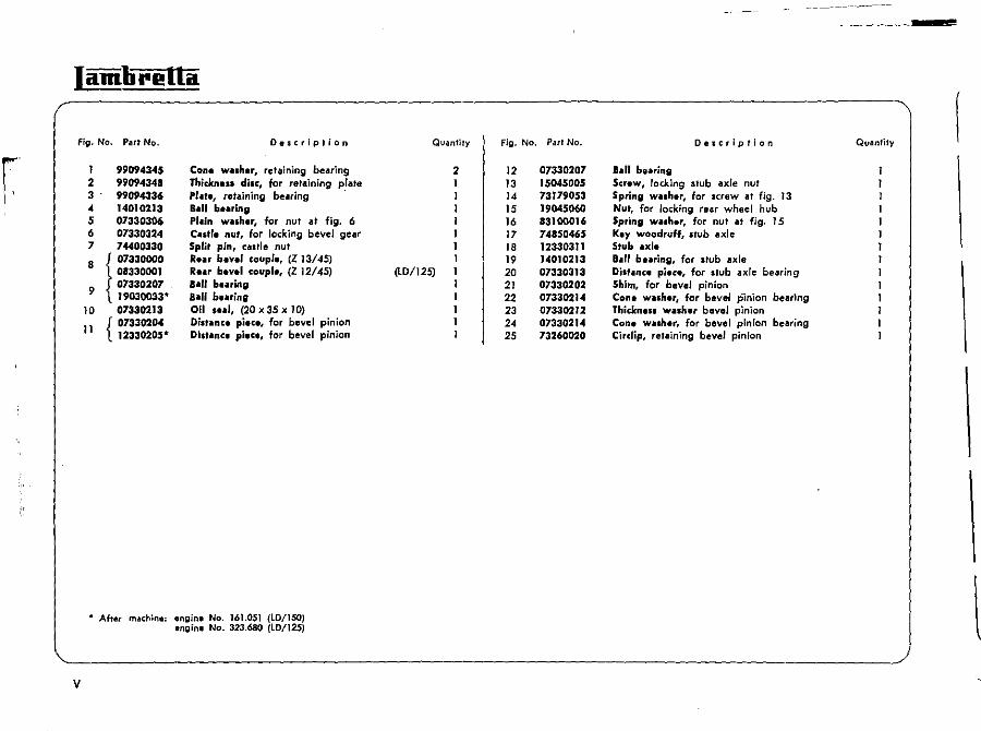
1 99094345 Con. wash.r, retaining bearing 2 99094348 Thicll:nus disc, for retaining p.'ate 3 99094336 P, .. t., retaining bearing 4 14010213 B.n b.aring 5 07330306 PI .. in w",h.r, for nut at fig. 6 6 07330324 coII.r. nut, for locking bevel gear 7 74400330 Split pin, castle nut
8 I 07330000 R • .., bev.1 coupl., (Z 13145)
{ 08330001 Rut bev.1 coupl., (Z 12145)
9 07330207 8 .. 11 buring 19030033* Ball b ... ring
10 07330213 Oil , ... 1, (20 x 35 x 10)
11 { 07330204 Di""nc. piec., for bevel pinion 12330205* Dilt"nc8 pi.c8, for bevel pinion
• After mad';ne: engine No. 161.051 (LD/ISO) engine No. 323.680 (LD/125)
--------.~
Quantity Fig. No. Part Ne. Description Quantity
2 12 07330207 8 .. 11 buring 13 15045005 Scr.w, locking stub axle nut 14 73179053 Spring w .. sh.r, for screw lit fig. 13 15 19045060 Nut, for locking rear wheel hub 16 83100016 Spring walh.r, for nut at fig. 15 17 74850465 k.y woodruff, Itub axle 18 12330311 Stub .xl. 19 14010213 B .. II be .. ring, for Itub axle
(lD/125) 20 07330313 Dil'oInc. pi.c., for Ilub axle bearing 21 07330202 Shim, for bevel pinion 22 07330214 Con. w .. ,h.r, for bevel pinIon bearing 23 07330212 Thickn.ss wash.r bevel pinion 24 07330214 Con. walh.r, for bevel pinion bearing 25 73260020 Circlip, retaining bevel pinion
l
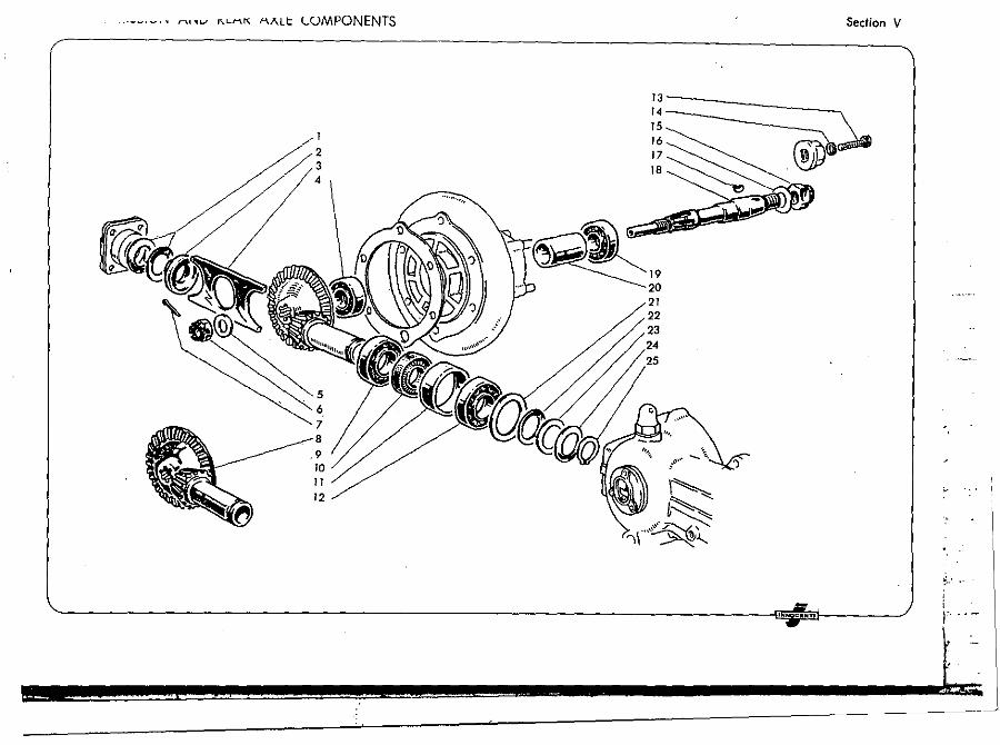
- . . ,-_.~ •• .... ·U .. I I\.LI""\'" AJ\.Lt LOMPONENTS
1
2 3 4
7
,9 10 11 12
•
19 20 21 22 23
Section V
'-------------------------------------------------------------------------~'~o; •. m"~------~
i :;
~.
, ; I' 'o-
r r.¥~
,,,morella
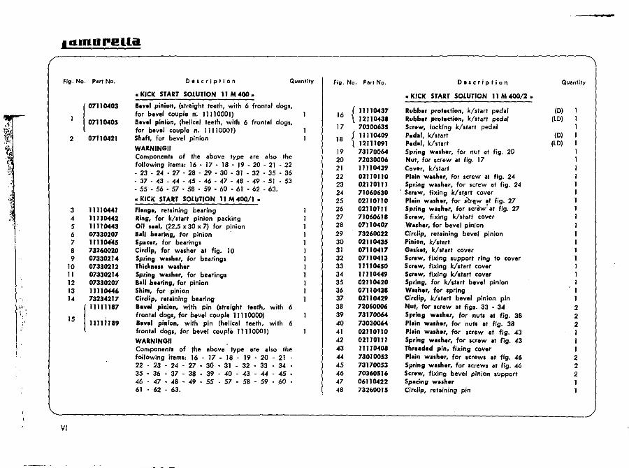
VI
Description Quantity
»KICK START SOLUTION II M 400 »
Bevel pinion, (straight teeth, with 6 frontal dogs, for bevel couple n·. Jl1l0001) 8evel pinion, (helical teeth, with 6 frontal dogs, for bevel coupl. n. 11110001) Sh .. ft, for bevel pinion
WARNINGII Component. of the above type lire a'so the following items: 16 . 17 • 18 • 19 . 20 - 21 . 22 . 23 . 24 . 27 . 28 . 29 . 30 . 31 . 32 . 3S . 36 ·D·G·~·a·~-47-~·.·SI-a ·55 - 56 - 57 • 58 . 59 . 60 ·61 ·62 - 63.
• KICK START SOLUTION 11 M 400/1 •
f'.n"., retaining bearing RinU, for k/start pinion packing Oi' I •• ', (22.5 x 30 x 7) for pinion a .. 11 b •• ring, for pinion Spuer, for bearings Circlip, for wilsher at fig. 10 Spring w •• h.r, for bearings Thiclr:nes. wa.h., Spring washer, for bearing. 8an b •• ring, for pinion Shim, for pinion Cirelip. r., .. inlng buring Bavel pinion, with pin (straight leeth, with 6 frontal dogs, for bevel couple 11110000) In.' pinion, with pin (helical teeth, with 6 frontal dogs, for bevel couple' 1110001) WARNINGII Components of the above type are also the following items: 16 - 17 - 18 - 19 - 20 - 21 a·D·~·V·~·31-a·~ N· U·~·D·~·.·~ G ~ a· ~ O·~·.·g·D·~·~ W· 61 - 62 - 63.
fig. No. Part No.
16 {11110437 12110438
17 70300635
18 {11110409 12111091
19 73170064 20 72030006 21 11}10439 22 02"0110 23 02110111 24 71060630 25 02110110 26 02110111 27 71060618 28 07110407 29 73260022 30 02110435 31 07110417 32 07110413 33 11110450 34 11110449 35 02110420 36 07110438 37 02110429 38 72060006 39 7317()06.4 40 73030064 41 02110110 42 02110111 43 11110408 44 73010053 45 73170053 46 70360516 47 06110422 48 73260015
Description
»KICK START SOLUTION 1 I M 400/2 •
Rubber prot.ction, k/start pedal Rubber protection, k/starl pedal Scr.w, locking klstart pedal p.dar, k/start P.dal, k/stllrl Spring washer, for nut al fig. 20 Nut, for screw at fig. 17 Cover, k/slart Plain washer, for screw at fig. 24 Spring washer, for screw at fig. 24
. Screw, fixing k/st~rt cover P'ain washer, for scrf.w ~f fig. 27 Spring wash.r, for screw' lit fig. 27 Screw, fixing klstart cover Washer, for bevel pinion Circlip, retaining bevel pinion Pinion, k/start Gasket, k/start cover Screw, fixing support ring to cover Screw, fixing k/sterf cover Screw, fixing kIster' cover Spring, for k/sfart bevel pinion Washer, for spring Circllp, k/start bevel pinion pin Nut, for screw at figs. 33 - 34 Spring washer, for nuts at fjg. 38 Plain washer, for nuts at fig, 38 Plain washer, for screw at fig. 43 Spring washer, for screw at fig. 43 Thr •• ded pin, fixing cover PI.in washer, for screws at fig. 46 Spring washer, for screws at fig. 46 Screw, fixing bevel pinion support Sp.cing washer Cirelip, retaining pin
Quantity
(D) (Lo)
(D) (LO)
2 2 2 I 1 1 2 2 2 1
K/START SOLUTION (11 M400- 11 M 400/2) 11 M400/1 - Section VI
50 51
63
. -:"
~ .. -1--_) ~ ... ~ -- -------1'%J1ro~~jJ'OO-"" \ ----------- I',;;;
'I""'""
........ u.-el.l.d
Fig. No. Pari No.
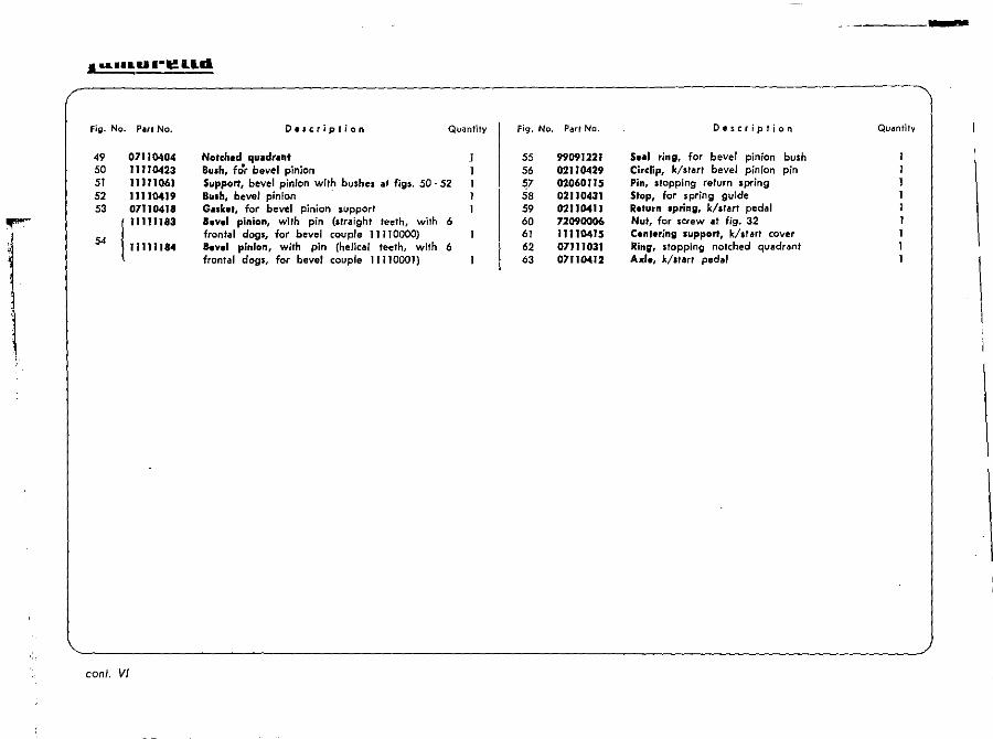
49 07110404 50 11110423 51 11111061 52 11110419 53 07110418
54 ! IIIJlJ83
11111184
conI. VI
Description
Notched quadr.nt Bush, for bevel pinion
Quantity
Support, bevel pinion with bushes at fjgs. 50·52 Bush, bevel pinion . Gulcel, for bevel pinion support a.v.1 pinion, with pin (straight teeth, with 6 frontal dogs, for bevel couple 11 T 10000) Bev.1 pinion, with pin (helic,,/ teeth, with 6 frontal dogs, for bevel couple 11110001)
Fig. No.
55 56 ~7 58 59 60 61 62 63
-----
Part No. Description Qu.mtily
99091221 5 •• 1 tins, 10' bevel pinion bush 0211042. eitelip, k/start bevel pinion pin 01060115 Pin, stopping return spring 02110431 Stop, for spring guide 0211041J Return spring. k/start pedal 72090006 Nut, for screw at fjg. 32 III 10415 Cent.ring support, kist art cover 07111031 Ring. stopping notched quadrant 07110412 Axl., k/.tar, pedal
\
l
K/START SOLUTION (] 1 M 400 - -11 M 400/1 - 11 M 400/2)
II
4 ~-----&.
Section VI
, IN .... CI(MTl
[;.. -~ i j.
l '"
Iam'lirl!Ua
Fig- No. Parr No.
1 2 3 4 5 6 7 8 9
10 11 12 13 14 15 16
17
18 19 20
21
22 23
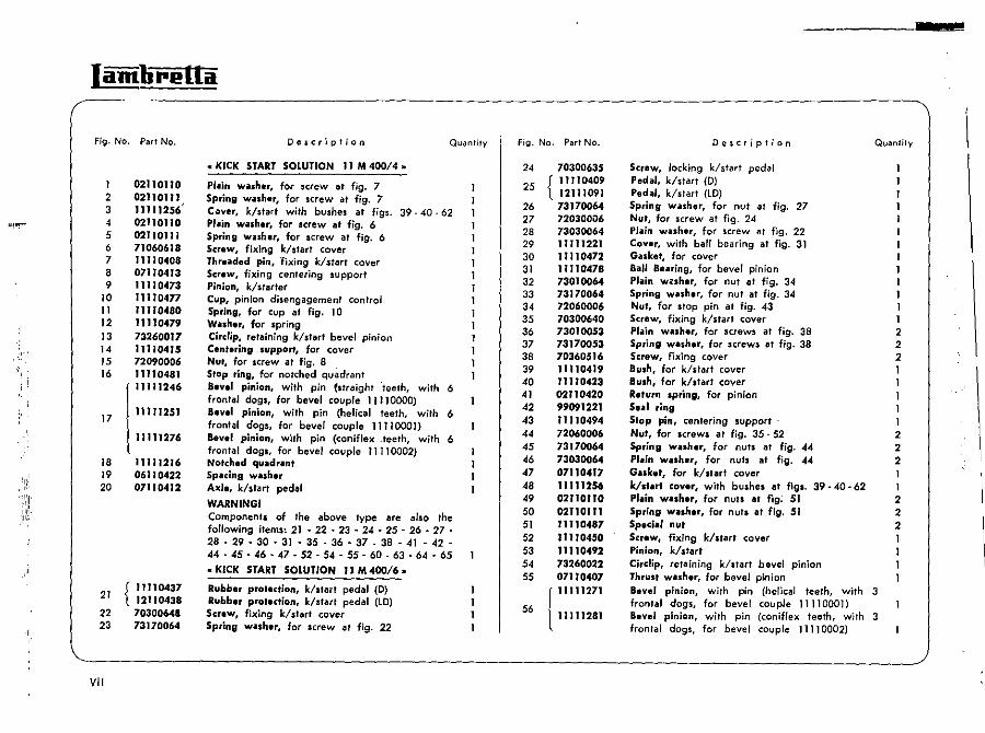
VII
02110110 02110111 11111256' 02110110 02110111 71060618 '1110408 07110413 11110473 11110477 11110480 11110479 73260017 11110415 72090006 11110481
1
11111246
111112S1
l1l111276
11111216 06110422 07110412
{ 11110437 12110438 7030064& 73170064
Description
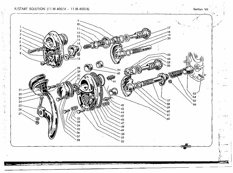
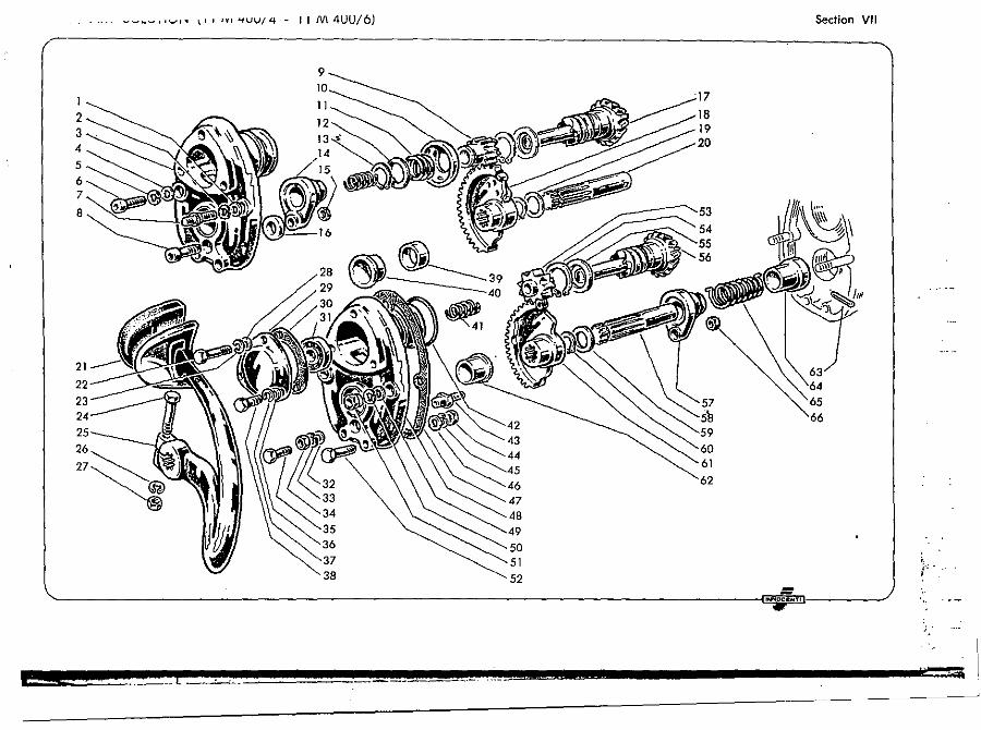
.. KICK START SOLUTION 11 M 400/4 ..
Plain wash.r, for screw at fig. 7 Spring washer, for screw at fig. 7
Quantity
Cover, k/start with bushes at figs. 39 - 40 - 62 PI.in wilsher, for screw at fig. 6 Spring WISher, for screw at fig. 6 Screw, fjxing klstart cover Thruded pin, 'fjxing k/start cover Screw, fixing centering support Pinion, k/starter Cup, pinion disengagement control Spring, for cup at fig. 10 Washer. for spring Cirelip, retaining k/start bevel pinion Cent.ring support, for cover Nut. for screw at fig. 8 Stop ring, for notched quadrant aevel pinion, with pin (straight teeth, wilh 6 frontal dogs, for bevel couple 11110000) aevel pinion, with pin (helical teeth, with 6 frontal dogs, for bevel couple 11110001) Bevel pinion, with pin (coniflex .teeth, with 6 frontal dogs, for bevel couple 11110002) Notched quadrant Spacing washer Axle. k/start pedal
WARNINGI Components of the above Iype are also the following items~ 21 - 22 - 23 - 24 - 25 - 26 • 27 -28 - 29 - 30 - 31 - 35 - 36·37 _ 38 - 41 ·42· M-45·46-47·~-~·~·60-~-64-65
• kiCk START SOLUTION I J M 40016 •
Rubber protection, kist art pedal (D) Rubber protection, k/start pedal (LD) Screw, fixing klstart cover Spring washer, for screw at fig. 22
Fig. No. Part No.
24
25
26 27 28 29 30 31 32 33 34 35 36 37 38 39 40 41 42 43 44 45 46 47 48 49 50 51 52 53 54 55
56
70300635
{ 11110409 12111091 73170064 72030006 73030064 11111221 1l 11 0472 11110478 73010064 73170064 72060006 70300640 73010053 73170053 70360516 11110419 11110423 02110420 99091221
" 110494 72060006 73170064 73030064 07110417 11111256 02110110 0211011, 11110487 11"0450 11110492 73260022 07110407
r 11111271
l1111128J
Description Quanfify
Screw, locking k/start pedal Pedal, k/start (0) Pedal, k/dart (lD) Spring woUher, for nut at fig. 27 Nut, for screw at fig. 24 PI.';n wilSher, for screw at fig. 22 Cover, with ball bearing at fig. 31 Gasket, for cover Ball Bearing, for bevel pinion Plain wC!sher, for nut lIt fig. 34 Spring washer, for nut at fig. 34 Nut, for stop pin at fig. 43 Screw, fixing k/start cover Plain washu, for screws at fig. 38 Spring washer, for screws at fig. 38 Screw, fixing cover Bush, for k/st"rt cover Bush, for k/start cover Return spring, for pinion Sui ring Stop pin, centering support Nut, for screws at fig. 35 - 52 Spring w.uher, for nuts al fig. 44 Plain wash.r, for nuts at fig. 44 Gasket, for k/start cover kJstart coyer, with bushes al figs. 39 - 40 - 62 Plain washer, for nuts at fig; 51 Spring washer, for nuts at fig. 51 Special nut Screw, fixing klslart cover Pinion, k/start Cirelip, retaining k/start bevel pinion Thrust washer, for bevel pinion Bevel pinion, with pin (helical teeth, with 3 frontal dogs, for bevel couple 11110001) Bevel pinion, wilh pin (coniflex teeth, with 3 frontal dogs, for bevel couple 11110002)
1 1 2 2 2 1 1
1 2 2 2
1 2 2 2 1 1 1 1
2 3 4
5 6 7
8
21
23
,----
'Section VII
64 65 66
k :\~ - .- .-
I
I i
.; ;
'/. ,
:1
Ia1ldirella
Fig. No. Part No. O.scription
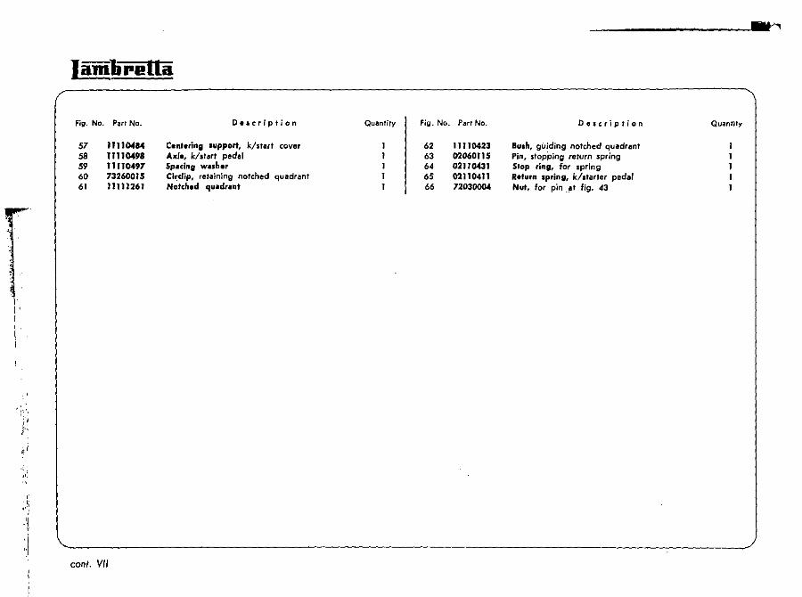
57 11110484 Cenl.rins support, k/start cover 58 11110498 Axl., k/start pedal 59 11110<197 Sp.cing wash.r 60 73260015 Cir:dip, retaining notched quadrant 61 11111261 Notch.d quad, .. n,
coni. VII
.'"'.
Quantity Fig. No. Part No. Description Quantity
62 11110423 Bu.h, guiding notched quadrant 63 02060115 Pin, stopping return spring 64 02110431 Stop ring, for spring 65 02110411 Return spring, k/starter pedal 66 72030004 Nut, for pin .~t fig. 43
4 4
· .... _~ ....... , ....... ," \', 'v-, "tvV/4 - I I M 4UU/6)
I 2 3 4
5 6 7
8
21
22
23
26
27~ @
9
35
38
_ [
Section VII
63
66
61
50
52
'iii
.,': .'!
Fig. No. Part No.
J 12110436 l 12110456
12111496
2 12111501 3 70300838 4 12110442 5 12110439 6 12110440 7 73260024 8 12110445 9 73170084
10 72030001 11 12110430 12 12110429 13 12110406 14 12110441 IS 73170084 16 73030084 17 12110419 18 11110478 19 70330860 20 73170084 21 73030084 22 73030064 23 73170064 24 72030006 25 87020001 26 74400330 27 83011201 28 73260024 29 12110431 30 12110441 31 12110404 32 15041024
VIII
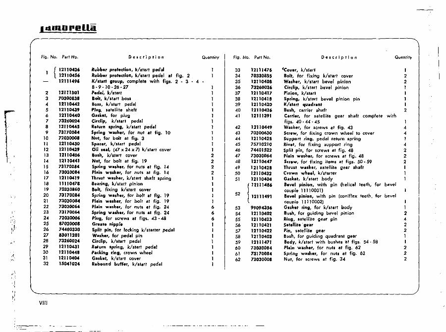
Description
Rubber protection, klstart pedal Rubber protection, k/slart pedal 011 fig. 2 K/slart group, complele with figs. 2 - 3 - 4 8-9-10-26-27 Pedal, klstarl Bolt, klstart boss Boss, k/start pedal Plug. satellite shaft Ga.ket, for plug Circlip, k/slarl pedal Return spring, k/slart pedal Sprin" wa.h.r, for nul at fig. 10 Nut, for bolt at fig. 3 Spater, k/slart pedal oil s .. I, (47 x 24 x n k/sterl cover Bu.h, k/start cover Nut, for bolt at fig. 19 Sprin" WISher, for nuls at fig. 14 Plain wtsher, for nuts al fig. 14 Thrust ~sher, klstart Ihaft spring Buring, k/ltart pinion Bolt, fixing klltart cover Spring WISher, for bolt at fig. 19 Plain WISher, for bolt at f;g. 19 Plain WISher, for nuts at fig. 24 Spring WISher, for nuts at fig. 24 Plug, for screwl at fjgs. 43· 48 Gr .. se nippl. Split pin, for locking k/starter pedal WISher, for pedal pin Cirelip, klstar. pedal Return sprins, k/start pedal Packing ring, crown wheel Gasket, klstart cover Rebound buffer, k/start pedal
QuantilY
I I I I 2 2 2 2 I I I I I 6 6 6 I I I I I
Fig. No. ParI No.
33 34 35 36 37 38 39 40 41
42 43 44 45 46 47 48 49 50 51
52
53 54 55 56 57 58 59 60 61 62
12111476 70330855 12110408 73260026 12110417 12110418 12110420 12110426 12111391
12110449 70300630 12110425 75710210 74401522 73030064 12110447 12110428 12lJ0432 12110404
! 12111486
12111491
99094356 12110402 12110423 12110421 12110422 12110403 12111471 73030084 73170084 72030008
Description Quantil),
~Cov.r, k/star. Bolt, for fixing klstart cover WlSh.r, k/start bevel pinion Cirelip, klstart bevel pinion Pinion, klstart Spring, k/start bevel pinion pin K/slart quadrant Bush, carrier Ihaft Carrier, for satellite gear shaft complete with figs. 40·44·45 Washer, for screws at fig. 43 Screw, for fixing crown wheel to cover Support ring, pedal return spring Rivel, for fixing support ring Splil pin, for screws al fig. 48 PI~in w~lher, for screws at fig. 48 Sc,ew, for fixing iteml at figs. 50·59 Th,ult washer, satellite gear shaft C,own wh.el, k/starter Gaske., k/starf body aevel pinion,. with pin (helical teeth, for bevel couple 11110001) Bev.1 pinion, with pin (can if/ex teeth, for bevel couple 11110002) Guke. ring, for k/start body Bush, for guiding bevel pinion Ring, satellite gear pin Sat.llite 'g.ar Pin, satellite gear BUlh, for guiding quadrant gear Body, k/start with bushel "at figs. 54·58 PI"in washer, for nuts at fig. 62 Spring washer, for nuts at fig. 62 Nut, for screws at fig. 34
2 2 I I I I 2
I 4 4 I 4 2 2 2
I I 2 4 2 2 I I 2 2 2
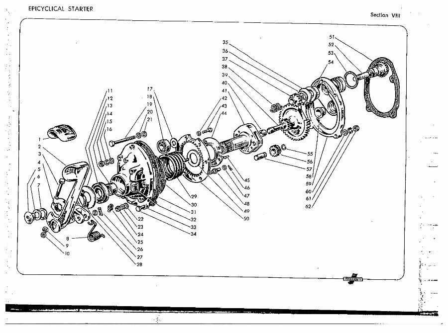
CEIP:I:CY~C=L~IC~A~L~S~T~A~R=T~ER~ ________________________________________ ----------~5;:~-----------'\ ~ " ( 35
Section VII-I
9
27
- ,j J
:: ..
36
37
49
INNOCIlNTI
Ie. , I '\" .-"
~, '" .\
'"
j-:'. I~.
\ ' I
I
, '"
I ilmlirl!Uil
Fig. No.
I 2 3 4 5 6 7 8 9
10 II 12 13 14 15 16 17 18 19 20 21 22 23 24 25 26 27 28 29 30 31 32 33 34 35 36 37
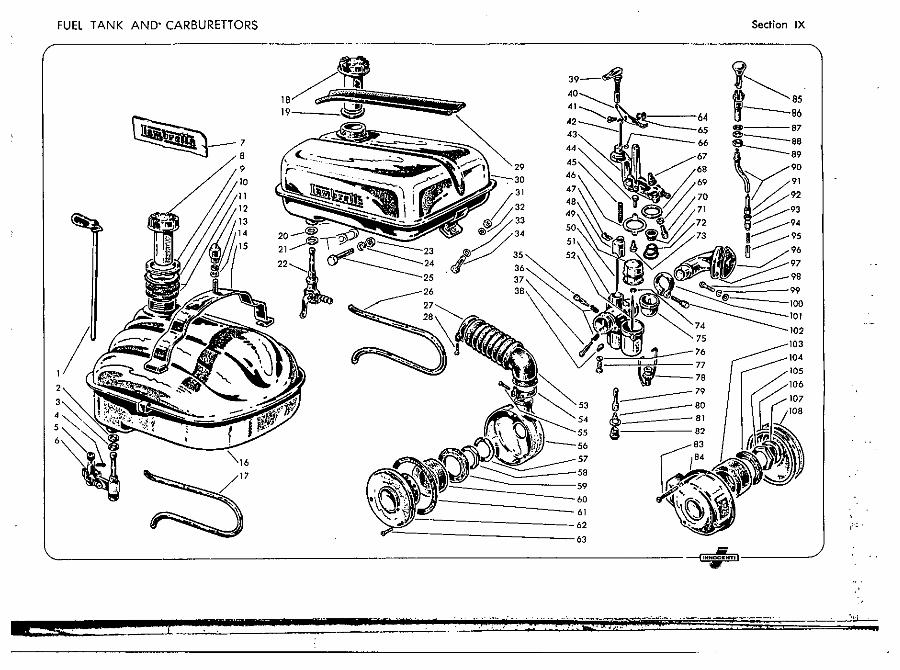
IX
Part No.
12171026 14070102 14070101 00412187 15071002 12171056 99097012 12170105 12170109 12170112 02170105 99098404 73030084 12170108 12171021 12171066 11170204 99097040 99097001 14070102 14070101 OS1n061 72030005 73170053 70330560 "'70204 12111431 70910420 99097008 11171001 72060006 06170108 73010064 70300622 00412042 00412004 00412026
2360
2115 1411 1532
Description Quantity
Rod, for petrol tap control G.uket, for petrol tap Gulcet, for petrol tap Spring pin, for rod Grommet, petrol tap control rod P.trol tillP (LD) Trillns'.r • Lambrefta ~ (D) FiII.r cap, fuel tank (without breather) Rins. locking fuel tank W .. h.r, for ring at fig. 9 Thickness wlllh.r Dome nut, fixing fuel fank PI .. in w .. h.r, for nut at fig. 12 Rubber washer, for fuel tank stirrup support Stirrup support, fuel tank Fu.1 t.nk (lO) P.trol pip. Fill.r c.p, fuel tank (with breather) G.sket, filler cap Gask.t, petrol tap Gubt, petrol tap Pelro' t.p (0) Nut, for screw at fig. 25 Spring w.sh.r, for screw at fig. 25 Screw, fixing fuel tank Petrol pipe Clip, retaining filter hose Screw, fjxing clip at fig. 27 Anlivibr.tion rubber, for fuel ta,,~
Fu.1 tank (0) CoulHerl1ut, fixing fuel tank Antivibration w.sher, for screw at fig. 34 PJain w .. her, for screw at fjg. 34 Screw, fixing fuel tank Scr.w, pilot iet adjustmenr Spring, adjustment scr~ws Screw, guiding and stopping air slide
I I 2
2 I I I
I ·1 2 I
Fig. No. P.ut No.
38 00412096 00412122 00412138 00412143
39 00412133 40 00412128 41 00412048 42 oo4J2037
43 { 00412J27 00412141
44 00412021 45 00412002 46 00412005 47 00412001 48 00412095 49 00412098 SO 00412135 51 {004)2137
00.4)2144 52 00412027 53 )2110716 54 12111431 55 70910420
00412180
56 00412184 57 Oo.t12131 58 0G412132 59 00412120 60 00412121 61 00412185 62 00412186 63 00412151 64 00412049 65 00412050 66 00412038
1488 MA 19 84 MA 19 B 4 MA 1884 3237 3124 2420 2321 3111 3382 1491 1409 1414 1407 1421 2390 2265 3232 3402 1607
3889
3783 315) 3154 3181 3159 3858 3859 1308 1973 1581 2383
Description Quanlily
Pilot j.t 45 C.,buretfor, without air- filter (0/150) C.rbur.llor, without air filter (LD/150}. C.,bureltor, without air filter (LO/12S) Lev.r, choke control Fulcrum I.v.r, choke control Pin, for fulcrum le ... er 0p.lI,ing rod, for air slide Co .... r, carburettor body (0) Cov.r, carburetlor body (lO) Scr.w, fixing carburettor cQ ... er Sprins, for air slide Gilsk.t, for carburettor co ... er R.taining clip, main jet needle Air slid. 75 Flo.t N.ed,. 03 C.,bureltor body Cubur.ltor body (LD/125J Ne.dl., for float Filt.r hOle (LD/epicyc/icaJ starter) Clip, fixing filter ho,e Scr.w, for fixing dip at fig. 54 Air filt.r, F 18, complete with figs. 56· 57 ·58 - 59·60·61 ·62·63 (LD/epicyclicll .tarter) Filt.r body T.b wash.r, locking nut Nut, locking filter body SpllC.r, for filter element Filt.r .I.ment Gasket, for end plate End plat., with cage retaining fjlter element Screw, fixing end plate Nut, locking fulcrum le",er pin Sprin" washer, for nut at fig. 64 Gasket, for operating rod
I 2
I I 3 I I
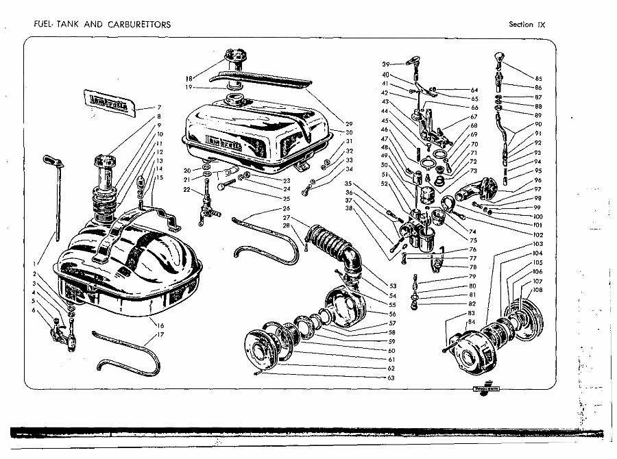
FUEL· TANK AN
4
5
6
D CARBURETTORS Section IX
~ 1~85 tl---e6
:= 87
~88
\ 89
i~:! ~93 ~94
':.,......---95 ~ 96
103
104
IamlireUa (
Fig. No. P!!rt Nc. Description Quantity
67 00412053 2439 Rubber. dust protector 68 00412056 2120 G •• ket, for filter bowl 69 00412054 1576 Count.rnut, f(lt adjustment screw 70 00412055 1575 Adjustment screw
71 00412057 2135 Filter 72 00412058 2109 SprinG. for filter 73 00412052 2275 S.,a" for needle 74 00412124 1452 Circlip, retaining needle 75 00412059 2114 Bowl, for tiltnr 76 00412126 2141 G.,ket, startel jet
r~ , I
77 J 00412125 2119 Stut.r j.t 50 l 00412139 2119 5tut., j.t 75
78 00412060 2192 Clip, for retaining filter bowl 79 00412097 2058 Atomiz.r 255!3
80 I 00412136 1486 Main jet 72 00412017 1486 Molin jet 75 (LD epicyclical starter) 00412100 1486 Milin j.t 68 (LD/l25)
81 00412006 141S Gillk.t, main jet plug 82 00412018 1487 Plug, main jet
00412134 3175 Air filt.r, F 14, complete with figs. 83· 84·103·104·105· 106·107·108 I
83 00412115 3153 Scr.w, for lecuring filter body end pl~te 3 84 00412142 3241 Filt.r body, complete with cages I 85 12111161 Knob, choke control I 86 12110708 Support, for choke control knob I
,,' ,
. conI. IX
Fig. No. Part No.
87 73030105 88 73170105 89 72070010 90 1211 1126 91 00412148 1104 92 00412054 1576 93 00412181 3128 94 00412182 3133 95 00412140 3238 96 J II II 0207
} 11110225 97 11110205
l II 110223 98 70360618 99 73170064
100 73030064 101 00412061 1721 102 00412062 1111 103 00412121 3159 104 00412120 3181 105 00412132 3154 106 00412119 3141 107 00412131 3151 108 00412130 3144
Description
Plilin will~.r, for nut at fig. 89 Spring willh.r, for nut at fig. 89 Nut, for choke control knob support Cilbl., choke control Adjult.r, for choke control cable Counl.rnut, for adjuster Adjus'.r nUl, for choke control cable Spring, for ch.:.ke control cable valve Viii .... , choke control Gilsk." for induction manifold Gilskllt, for induction manifold (LD/12S) Manifold induction Milnifold induction (LD/l25) Scr.w, fixing induction manifold Spring wiillh.r, for screws at fig. 98 PliI;n wilsh.r, for screws at fig. 98 Ring, for securing carburetfor Scr.w, for ring Itt fig. ]01 Filtar .rement Spacer, for filter element Nut, locking end plate Gask.t, for filter body T.b willh.r, for nut at fig. 105 End pl.t., fjlter body
Quantity
I 3 3 3 I I I I I
FUEL TANK AND" CARBURETTORS
4
5 6
A g. . .F n • ---.
Section IX
103
~======61 62
63
---t'N#NT" ___ ~
Iamlirl!Ua
Fig. No. Part No.
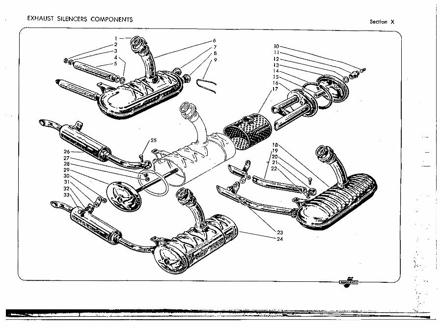
1 07180405 2 72060008 3 73120084 4 11180449 5 11)81206 6 11184001
7 '1180458 8 15056028 9 11180469
10 99095627 11 99095626
''''"' 12 99095628 13 07181111 14 07180422
.' 15 07180434
~ 16 11181146
17 { 1111043P 12180439
" :!'
·1'·'
t; :',j:
'--~,-~- --
Description
G.-ket, for silencer Nut, for fixing exhaust tube Sprins wash." for nut at fig. 2 Ga,Jc.t, for exhaust tube Exhaust tub.
Quantity
Silencer, complete with figs. 2 - 3 . 4 . 5 - 7 - 8 • 9 (0/150) P'ug, with extension for silencer Plug, for .ilencer Wir •• for securing silencer plugs Grub, for .ecuring bUlh BUlh, for end plate rod 1 GlIsk.t, for bush I End pJill., with support 1 Gillket, for end pl.fe 2 Spilcer 1 Sliding dillphrllgm, with tubes 1 Filler (D) 1 Fill.r (LD)
Fig. No. ParI No,
18 12184003 19 12181431 20 70490515 21 12180486 22 72030005 23 70610814
24 { 11180400 12180400
25 70300525
26 { 11181161 12181191
27 73170053 28 72000005 29 07181141 30 72060008 31 11181166 32 73170084 33 11180442
Description Quantity
Silencer, complete with figs. 19 - 20 - 21 - 22 (LO) Exhllust tube Screw, fixing e'Xhllust tube Clllmp, fixing exhaust tube Nut, for Icrew at fig. 20 Screw, fixing exhaust tube Silencer, complete (D) SiI.ncer, complete (tD) Screw, fixing exhllust tube to silencer Exh,.ust pipe (D) Exhllus, pipe (lD) Spring willher, for screw at fig. 25 Nu., for screw at fig. 25 End pillte, with rod Nut, for Icrewl at figs. 23 - 33 P'II'e, fixing exhaust pipe Spring wlisher, for screwl at figl. 23 - 33 Screw, for fixing exhaust pipe
EXHAUST SILENCERS COMPONENTS Section X
(
INNOCIU<T,
.':
! : I w
Iamlirl!lla
Fig. No. Par, No. Oescription Quantity Fig. No. Part No. DeJcriplion Quantity
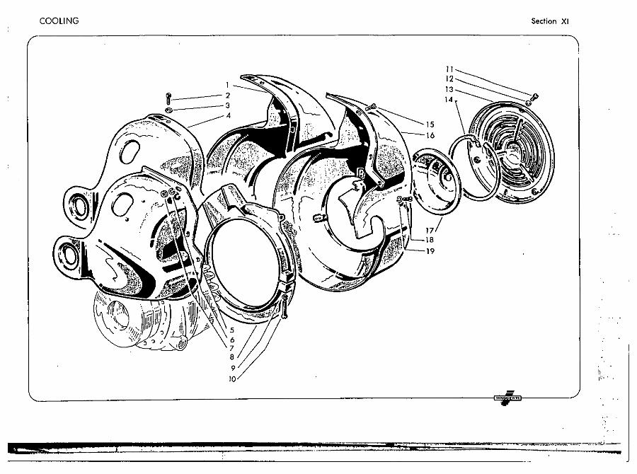
Not supplied, ;t ;. necessary to replace the 10 71220525 Scr.w, fixing flange 1 engine cowl with figs. 5· 16 11 71430409 Scr.w, fixing main cowl cover 3
2 70920407 Screw, fixing engine cowl 3 12 11110514 Spring w.sh.r, for screws at fig. 11 3 3 83100004 Spring wIsh.r, for screw at fig. 2 3 13 11110506 Cov.r, 10' main cowl 1 4 11111116 Engin. cowl, drive lide 1 14 15014009 ei,elip, for dUlt protector cover 1 5 11111366 Engin. cowl, drive side 1 15 70910509 Screw, fixing engine cowl 3 6 73170053 Spring walh.r, for Icrews " fig. 15 3 16 11111361 Engin. cowl, flywheel side 1 7 72030005 Nut, for screws at fig. 15 3 17 15014010 Cov.r, dust protector 1
• 11110502 Fhlng., flywheel side cowl 1 ,. 70910512 Screw, fixing engine cowl 10 flange 3 9 73170053 Spring w •• h.r, for screw lit fig. 10 1 19 73170053 Spring wuh.r, for screws at fig. ,. 3
XI
COOLING
1----2 _---3 4
9
10
: , iN .. _0
Section XI
"\ I
II
13
' .... oeluOT.
- '''''.':~--
.. ow
:i ill· " ,Ill
f' "
Ii , j]
Ii ! I d :Iii
Iamlirl!lla ~--------------------------------------------------------~
\
Fig. No. Part No.
2
3 4
5
6 7 8 9
10 11
12
13 14 15 16 17 18
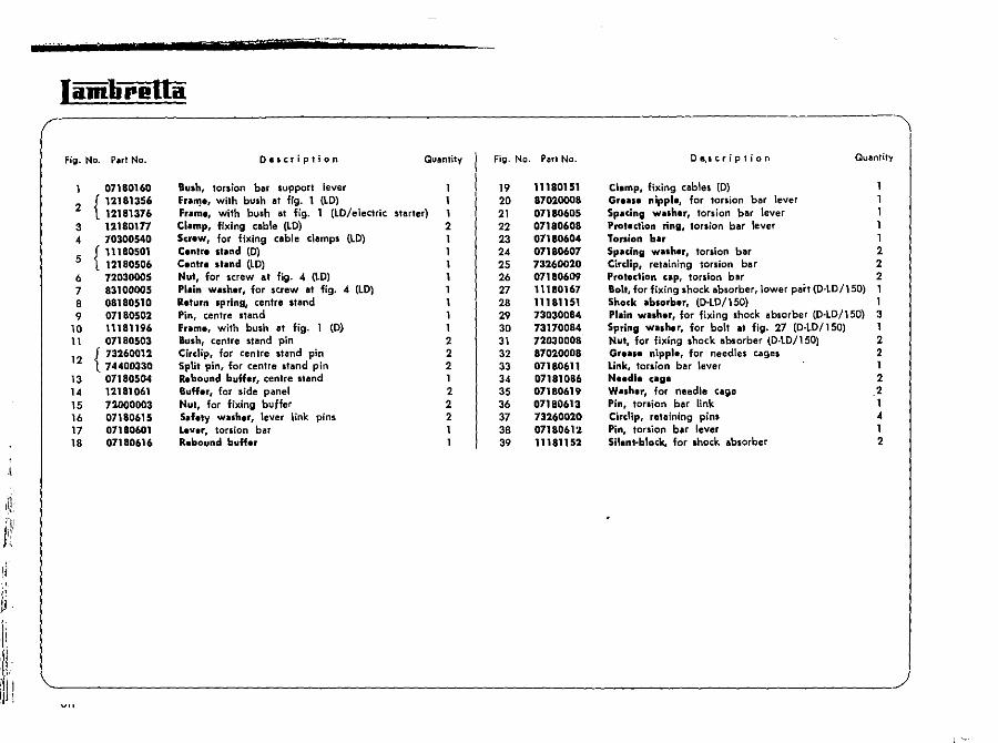
07180160
{ 12181356 12181376 12180177 70300540
{ 11180501 12180506 72030005 83100005 08180510 01180502 11181196 07180503
{ 73260012 74400330 01180504 12181061 72000003 07180615 01180601 07180616
Quantity
Bush, torsion bar support lever Fnu~., with bush at fig. 1 (LD) fram •• with bush at fig. 1 (LD/electric starter) Clamp, fixing cable (LO) Screw, for fixing cable clamps (LD) C.nlr. stand (0) Centre 'hind (lD) Nut, for screw at fig. 4 (LD) PI.in washer, for screw at fig. 4 (LO) R.furn spring, centre stand Pin, centre stand Frame. with bush lit fig- 1 (0) Bush, centre stand pin Cirdip, for centre stand pin Split pin, for centre stand pin Rebound buKer, centre stand Buff.r, for side panel Nul, for fixing buffer Saf.ty wnh.r, lever link pins L.ver, torsion bar Rebound buH.r
1 1 1 2 1 1 1 1
1 2 2 2 1 2 2 2
Fig. No. Part No.
19 20 21 22 23 24 25 26 27 28 29 30 31 32 33 34 35 36 37 38 39
11180151 87020008 07180605 07180608 07180604 07180607 73260020 07180609 11180167 11181151 73030084 73170084 72030008 87020008 07180611 07181086 07180619 07180613 73260020 07180612 11181152
o e.s c rip I ion QuanTiTy
Clamp, fixing cables (D) 1 Gr.as. nipple, for torsion bar lever 1 Spacing wash.r, torsion bar lever 1 Protection ring, torsion bar \ever 1 Torsion bar 1 Spacing wash.r, torsion bar 2 Cirelip, retaining torsion bar 2 Protection cap, torsion bar 2 Boll, for fixing shock absorber, lower part (o'lD/1S0) 1 Shock absorber. (O-l0/150) 1 Plain wash.r, for fixing shock absorber (O'lO/IS0) 3 Spring washer, for bolt at fig. 27 (D·lD/1S0) 1 Nul. for fixing shock absorber (D·lo/ISO) 2 Gr.as. nippl., for needles cages 2 Link, torsion bar lever 1 N •• dl. cage 2 Washer, for needle cage 2 Pin, torsion bar link 1 Circllp, retaining pins " Pin, torsion bar lever 1 Silent·block, for shock absorber 2
FRAMES AND SUSPENSIONS Section XII
, ;1·~ .
• _. __ r -=-,_~. __ _ ,-~-
1
I
t " ."
1\ ;1 :1
:1
1,11,,1
ill IH
en *; . t j ;z;- a;;r 11
Iamlirella
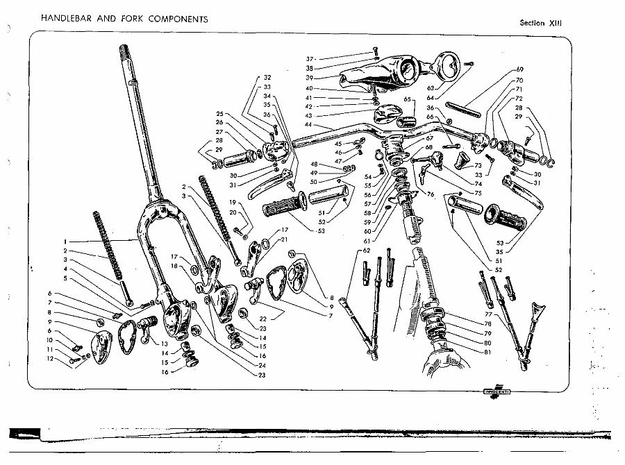
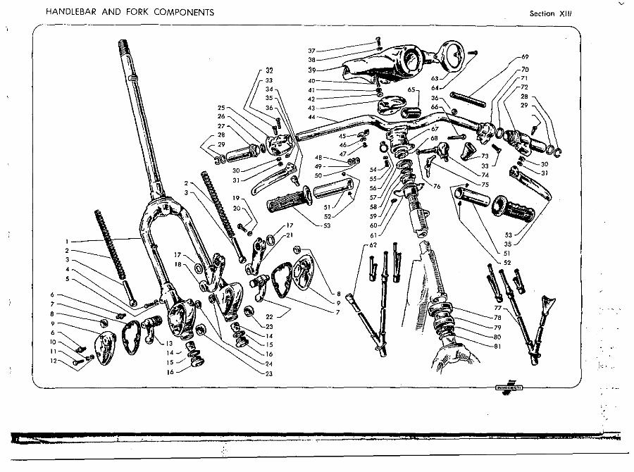
Fig. No. Put No.
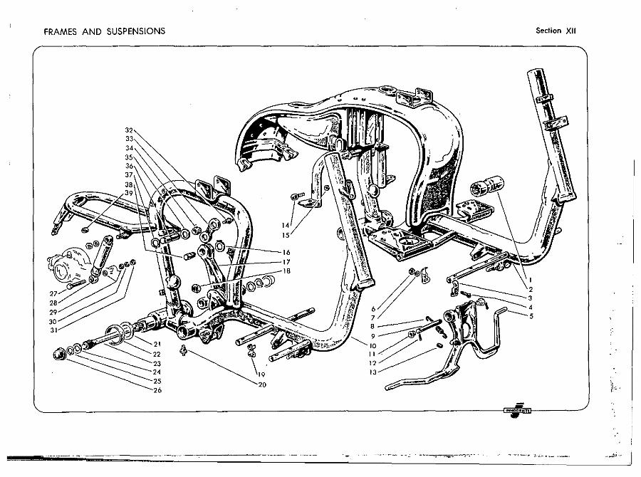
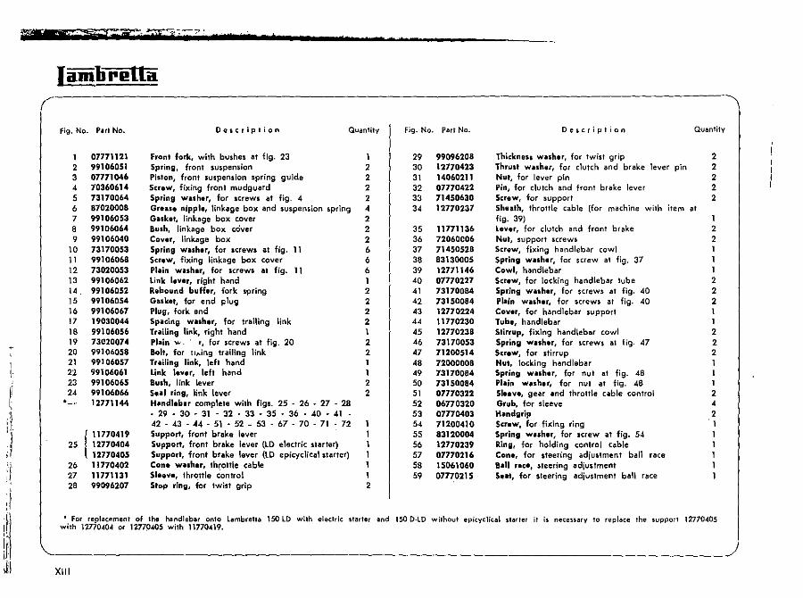
1 07771121 2 99106051 3 07771046 4 10360614 5 13170064 6 87020008 7 99106053 8 99106064 9 99106040
10 73170053 11 99106068 12 73020053 13 99106062 14 99106052 15 99106054 16 99106061 17 19030044 18 99106056 19 73020074 20 99106058 21 99106057 21 99106061 23 99106065 24 99106066 *- 12771144
111770419
25 12770404 12770405
26 11770402 27 11771131 28 99096207
O\i$cription Quantity
Front fork, with bushes at fig. 23 1 Spring, front suspension 2 Piston, front suspension spring guide 2 Screw, fixing front mudgullrd 2 Spring washer, for screws al fig. 4 2 Greiue nipple, linkage box and suspension spring 4 Gaskel, linkage box cover 2 Bush, linkage box cciver 2 Cover, linkage box 2 Spring washer, for screws at fig. 11 6 Screw, fixing linkage box cover 6 Plain washer, for screws at fig. 11 6 Link lever, right hand 1 Rebound buffer, fork spring 2 Gasket, for end plug 2 Plug, fork end 2 Spacing washer, for trailing link 2 Trailing link, right hand 1 Plain v.. r, for screws at fig. 20 2 Bolt, for II .... in9 trailing link 2 Trailing link, left hand 1 Link lever, left hand 1 Bush, link lever 2 Seal ring, link lever 2 Handlebar complete with figs. 25 • 26 • 27 • 28 ·~·m·31·U·a·U·M·~·41
G·a·«·51·~·~·~·~·71·n Support, front brake lever Support, front brake lever (lO electric stllrter) Support, front brake lever (lO epicyclical starter) Cone washer, throttle cable Sleeve, throttle control Stop ring, for twist grip 2
. -
Fig. No. Part No.
29 99096208 30 12770423 31 14060211 32 07770422 33 71450630 34 12770237
35 11771136 36 72060C06 37 71450528 38 83130005 39 12771146 40 07770227 41 73170084 42 73150084 43 12770224 44 11770230 45 12770238 46 73170053 47 71200514 48 72000008 49 73170084 50 73150084 51 07770322 52 O6n0320 53 07770403 54 71200410 55 83120004 56 12770239 57 07770216 58 15061060 59 07770215
Oe~cription Quantity
Thickness washer, for twist grip 2 Thrusl washer, for clutch and brake lever pin 2 Nut, for lever pin 2 Pin, for clutch and front brake lever 2 Screw, for support 2 Sheath, throttle cable (for machine with item at fig. 39) 1 Lever, for clutch and front brake 2 Nut, support screws 2 Screw, fixing handlebar cowl 1 Spring w,.sher, for screw at fig. 37 1 Cowl, handlebar 1 Screw, for locking handlebar tube 2 Spring washer, for screws at fig. 40 2 Plain washer, for screws al fig. 40 2 Coyer, for handlebar support 1 Tube, handlebar 1 Stirrup, fixing handlebar cowl 2 Spring wuher, for screws al fig. 47 2 Screw, for stirrup 2 Nut, locking handleb!lr Spring WISher, for nut at fig. 48 Plain washer, for nut at fig. 48 1 Sleeve, gear and throttle cable control 2 Grub, for sleeve 4 H,.ndgrip 2 Screw, for fixing ring 1 Spring washer, for screw at fig. 54 1 Ring, for holding control cable 1 Cone, for steering adjustment ball race 1 a,.11 r.ce, steering adjustment 1 Se.t, for steering adjustment ball race 1
• For replacf!ment of lhe n!lndleb!lr onto L!lmbretta 150 lD wilh eleclric slarler and ISO D·LO wilhout epicyc1ical .Iarler il is necenary 10 replace 'ne ~uppo~' 12770405 with 12770404 Of 12770405 with 11770419.
~-_____________________________________________________ J XIII
HANDLEBAR AND FORK COMPONENTS
6
7
•
1 ---1 ---\\'\\ 2 _____________
3
4
5
16
.:c.
Section XIII
32
23
'NNOCIENT,
:' .... C '-
Iamlirl!Ua
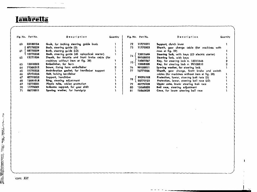
Fig. No. Part No. D.scription
60 05180124 Grub, for locking steering guide bush r 07770229 Bush, steering guide (0)
61 l 08770229 Bush. steering guide (LO) 12770233 Bush, steering guide (lO epicyclical starter)
62 12771036 Shuth. for throttle and front brake cable machines without item at fig. 39)
63 12010303 Embellish.r, for horn
6' 71500312 Screw, fixing horn embellisher 65 11770225 Antivibration gaske., for handlebar support 66 0177022.6 Bolt, locking handlebar 67 07170223 Support, handlebar 68 15061018 Ring, steering adjustment 69 12770221 Plastic tube, cables protection 70 11770301 Indicillor support. for gear shift 71 06770311 Spacing washer, for handgrip
conI. XII'
QUantity fig. No. Part No.
72 11771011 73 11770303
f 12011640 (for 74 99108810
1 5 15081037 1 7 15088005 2 76 99108811 1 77 12771026
78 f 990'10108 1. 05770121
79 40770228 80 15060020 81 15060021
Delc.ription Quantity
Support, clutch lever Sh .. th, gear change cable (for machines with item at fig. 39) 1 Sleering locle, with keys (LO electric starter) 1 Steering lock, with keys 1 Key, for steering lock n. 12011646 2 Key, for steering lock n. 99108810 2 Spilcing washer, for steering lock Sheath, gear ch!loge, front brake and switch c!lbles (for machines without item at fig. 39) Proleclion, lower, steering ball race (0) Protection, lower, ~teering ball race (LD) Upper cone, lower steering ball race Ball race, steering adjustment Cone, for lower steering ball rllce
~-"-~~--------_i
HANDLEBAR AND /" FORK CO / MPONENTS Section XIII
"\
3.
32 33
3' ., 35 42 36 '3
••
.N .... CIl To
Iamlirl!Ua
FiU. No. Par! No.
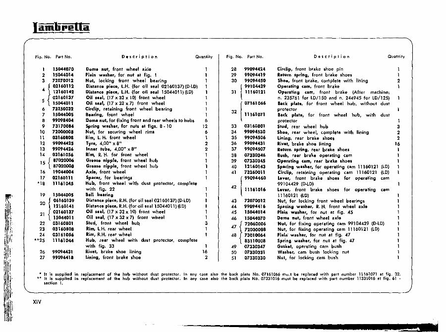
1 15044070 2 15044014 3 72070012
{ 02160112
4 12160142 5 { 02160137
15044011 6 73250032 7 15044005 8 99098404 9 73170084
10 72000008 11 03160108 12 99094425 13 99094426 14 03161056 15 { 87020006
87020008 16 19044004 17 02160111
*18 11161045
19 15044005 20 ! 06160139
{
12160141 21 02160137
15044011 22 03160801 23 03160808 24 0316105,
**25 11161044
26 99094431 27 99094418
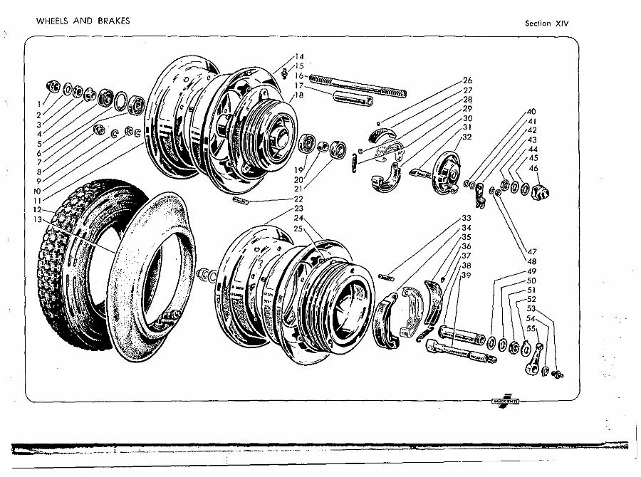
XIV
It is supplied II is supplied section I.
DescriPtion
Dome nut, front wheel aide Pillin wlllh.r, for nut at fig. NUl, lockIng front wheel bearing
Quantity
Di.tlln,. pi.c., l.H. (for oil seal 02160137){D·lO) Distlln,. pi.,., l.H. (for oil leal 15044011) (lO) Oil .u1, (17 x 32 x 10) front wheel Oil '.111, (17 x 32 x n front wheel Circlip, retaining front wheel bearing 1 B.llring, front wheel 1 Dom. nut, for fixing front and rear wheels to hubs 6 Spring w •• h.r, for nuts at figs. 8 -10 12 Nut, for securing wheel riml 6 Rim, l. H. front wheel 1 lyr., 4,00" x 8" 2 Inn.r tub., 4,00" x 8" 2 Rim, R. H. for front wheel 1 Gr.II •• nippl., front wheel hub 1 Gr.llle nippl., front wheel hub 1 Axl., front wheel 1 Spacer, for bearingl 1 Hub, front wheel with dust protector, complete with fig. 22 BlIl1 buring Distanc. pi.c., R.H. (for oil seal 02160137) (O-lO) Distan,. pi.,., R.H. (for oil seal 150440\ 1) (LO) I Oil sui, (17 x 32 x 10) front wheel 1 Oil s •• I, (17 x 32 x 7) front wheel 1 Stud, front wheel hub: 3 Rim, L.H. rear wheel Rim, R.H. rear wheel Hub, rear wheel with dust protector, complete with fig. 33 1 Rivet, brake shoe lining 16 lining, front brake shoe 2
Fig. No. Part No.
28 99094424 29 99094419 30 99094450
31 11160121 \
99104429
r 07161066
32 l'1161071
33 03160801 34 99094530 35 99094506 36 99094431 37 99094507 38 07330346 39 07330345 40 12160143 41 73260011
J 99094460
42 l'1161016
43 72070012 44 99094416 45 15044014 46 15044070
.7 t 72060006 72030008
48 73010064 83110008
49 07330347 50 07330331 51 07330330
Description Quantity
Circlip, front brake shoe pin 1 Return spring, front brake shoes 1 Shoe, front brake, complete with lining 2 Operating urn, front brake Oper.ting urn, front brake (After machine: n. 235761 for LO/150 and n. 244945 for LD/125) Back plat., for front wheel hub, without dust protector Back pl ••• , for front wheel hub, with dust protector 1 stud, rear wheel hub 3 Sho., rear wheel, complete with lining 2 Lining, rear brake .hoel 2 Rivet, brake .hoe lining 16 R.turn spring. rear brake Ihoe. Bush, rear brake operating cam Op.r.ting um, rear brake .hoel Splicing wlllh.r, for operating cam 11160121 (LO) Circlip, retaining operating cam 11160121 (LO) lev.r, front brake Ihoes for operating cam 99104429 (D·LD) l.v.r, front brake shoes for operating cam 11160121 (LD) Nut, for locking front wheel bearings Splicing w.sh.r, R. H. front wheel axle PI.in w.sh.r, for nut at fig. 45 Dom. nut, front" wheel axle 'Nul, for fixing operating cam 99104429 (O·LO) Nut, for fixing operating cam 11160121 (LO) Plai
" wlIsh.r, for nut at fig. 47
Spring wash.r, for nut at fig. 47 Gask.t, operating cam bush Wlllh.r, cam bush locking nut Nut. for locking cam bush
in replacement of the hub without dust protector. In any case also the back plate No. 07161066 mu.t be repll1ced with pnl number 1\ 161071 al fig, 32. in replacement of the hub without dust protector. In any Cine aha the back plale No. 07331016 mus' be replaced with parI number 11331016 at fig. 61 •
-------------------.. ~~ ...
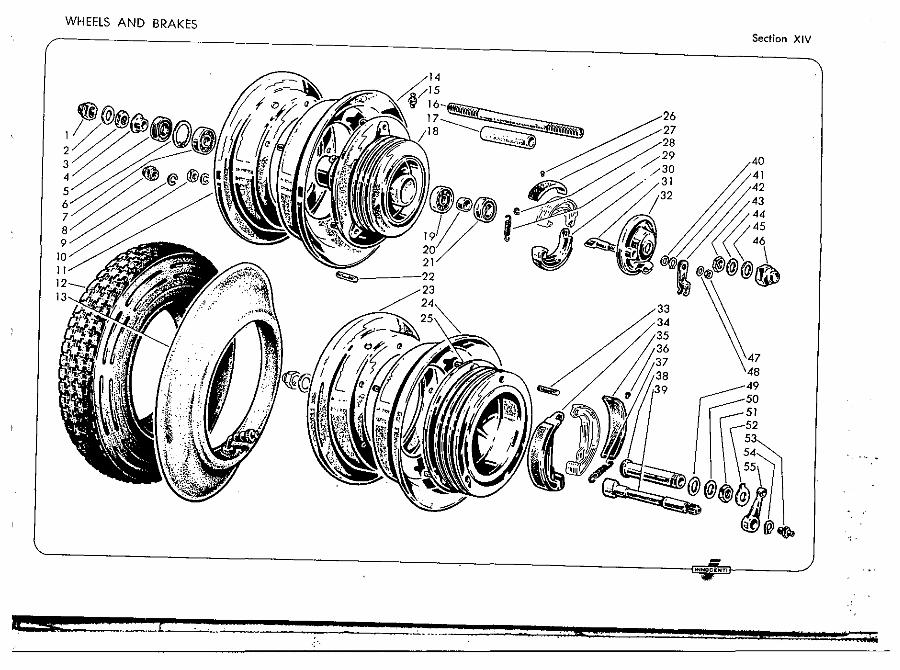
WHEELS AND BRAKES Section XIV
"'~OCI:HTI
IamlireUa
Fig. No. Pari No.
52 07330333 53 87020006
coni. XIV
Description
Tab wisher, cam bush locking nut Grane nippl., for operating cam
Quantity Fig. No. Part No.
54 73260011 55 07330332
DescriptioI"':
Circlip, retaining rear brake operating luver Op.t<1lting lev.r, rear brake control
Quantity
AND BRAKES WHEELS
iO II 12~_/A
IJ~,J'J!
, S-. t _ .. __ - . ___ . __
Section XIV
IHHIIC."T,
it n.\Ii
--------------------------------------------------------------
1 I I II I: ~.
I amli PI! llil
fig. No. part No.
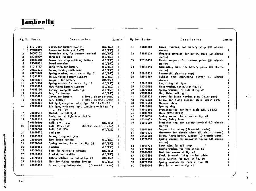
{ 11010466 19081032
2 14080102 3 11011177 4 19081170 5 70880430 6 15081029 7 15081031 8 72030005 9 73170053
10 12 11 , .. :,,451 12 70850406 13 73170043 14 11010611 15 07011221 16 07010603 17 71020525 18 11010608 19 7)020530 20 12011201 21 73170043 22 70850406 23 71360512 24 73170053 25 72030005 26 07011067 27.· 99098304 28 87200008 29 12011526 30 12011501 31 12010464 32 70360510 33 73170053
34 72000005 35 70910310
xv
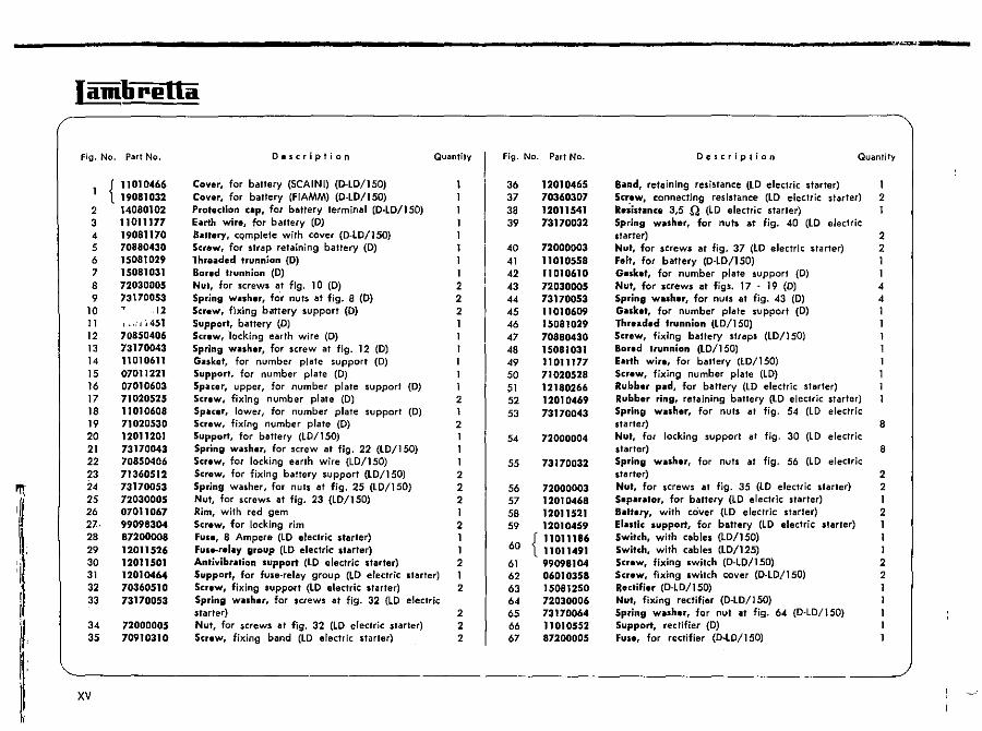
Description
Cover. for battery (SCAINI) (O·LD/150) Cover, for battery (FlAMM) (D-lD/ISO) Protection up. for battery terminal (D-LD/ISO) hrth wir., for battery (D) Biiluery, cQmplete with cover (D·lD/ISO) Screw, for strap retaining battery (D) Threaded trunnion (D)
Quantity
Bored trunnion (D) 1 Nut, for screws III fig. 10 (D) 2 Spring wuher, for nuls at fig. 8 (D) 2 Screw, fixing battery support (D) 2 Support, battery (D) 1 Screw, ·Iocking earth wire (D) I Spring willSher, for screw at fig. 12 (D) 1 Guket, for number plate support (D) I Sup pori. for number plate (D) Sp~cer, upper, for number plate support (D) Screw, fixing number plate (D) 2 Spacer, lower, for number plate support (D) 1 Screw, fixing number plate (D) 2 Support, for battery (lO/IS0) 1 Spring wuher, for screw at fig. 22 (lD/1S0) 1 Screw, for locking earth wire (lO/150) 1 Screw, for fixing battery support (LD/150) 2 Spring washer, for nuls at fig. 25 (lO/150) 2 Nut, for screws at fig. 23 (LD/150) 2 Rim, with red gem I Screw, for locking rim 2 FUse, 8 Ampere (LD electric stllrter) I Fuse-relilY group (lD electric sfllrter) I Antivibration support (lD electric stllrter) 2 Support, for fuse-reillY group (lD electric starter) 1 Screw, fixing tupport (lD electric starter) 2 Spring willSher, for screws at fig. 32 (lD electric starter) 2 Nut, fOr screws lit fig. 32 (lD electric slarler) 2 Screw, fixing blind (lO electric starter) 2
Fig. No. Pllrt No.
36 12010465 37 70360307 38 12011541 39 73170032
40 72000003 41 11010558 42 11010610 43 72030005 44 73170053 45 11010609 46 15081029 47 70880430 48 15081031 49 11011177 50 71020528 51 12180266 52 12010469 53 73170043
54 72000004
55 73170032
56 72000003 57 12010468 58 12011521 59 12010459
60 {11011186 11011491
61 99098104 62 06010358 63 15081250 64 72030006 65 73170064 66 11010552 67 87200005
Description Quantity
Bilnd, retaining resistance (lO eleclric starter) Screw, connecting resistance (lO electric starter) 2 Reiistilnc. 3,5 .Q (LO electric starter) 1 Spring wilsher, for nuts at fig. 40 (LO electric starter) 2 Nut, for screws at fig. 37 (LD electric starter) 2 Felt, for bllttery (D·LO/150) I Gasket, for number plate support (D) I Nut, for screws at figs. 17 . 19 (D) 4 Spring washer, for nuts al fig. 43 (D) 4 Gasket, for number plate support (D) I Threaded trunnion (LOll 50) 1 Screw, fixing battery straps (LD/150) Bored trunnion (LD/150) Earth wire, for battery (LD/ISO) Screw, fixing number plate (LO) Rubber pild, for battery (LD electric starter) Rubber ring, retaining battery (lD electric starter) Spring wilSh.r, for nuts at fig. 54 (LD electric slarter) 8 Nut, for locking support at fig. 30 (LO electric starter) 8 Spring washer, for nuts at fig. 56 (LD electric starter) 2 Nut, for screwJl al fig. 35 (lD electric starler) 2 Sepilriltor, for bllttery (lO electric starfer) I BiI"ery, wilh cover {lD electric stllrter} 2 ElilStic support, for battery (lD electric starter) 1 Switch, with cllbles (lOll 50) 1 Switch, with cables (lD/125) 1 Screw, fixing switch (D-lD/150) 2 Screw, fixing switch cover (o·lO/ISO) 2 Itectifier (D-LO/150) 1 Nut, fixing rectifi.r (D-lO/150) I Spring washer, for nut at fig. 64 (D·lo/ISO) I Support, rectifier (D) I Fuse, for rectifier (D·LO/150) 1
ELECTRICAL EQUIPMENTS (0/LO/1956 - LO/1956 ELECTRIC STARTER) Section XV
'. -- .
,;.
~.------------------------------------------------------------------------------------~,.~ •• ~ •• ~··w'r--------/
4 & • 1 ... "4; ....
Illl [
I , i
, I
i! I
Jamlirl!lla
Fig. No. P"r! No.
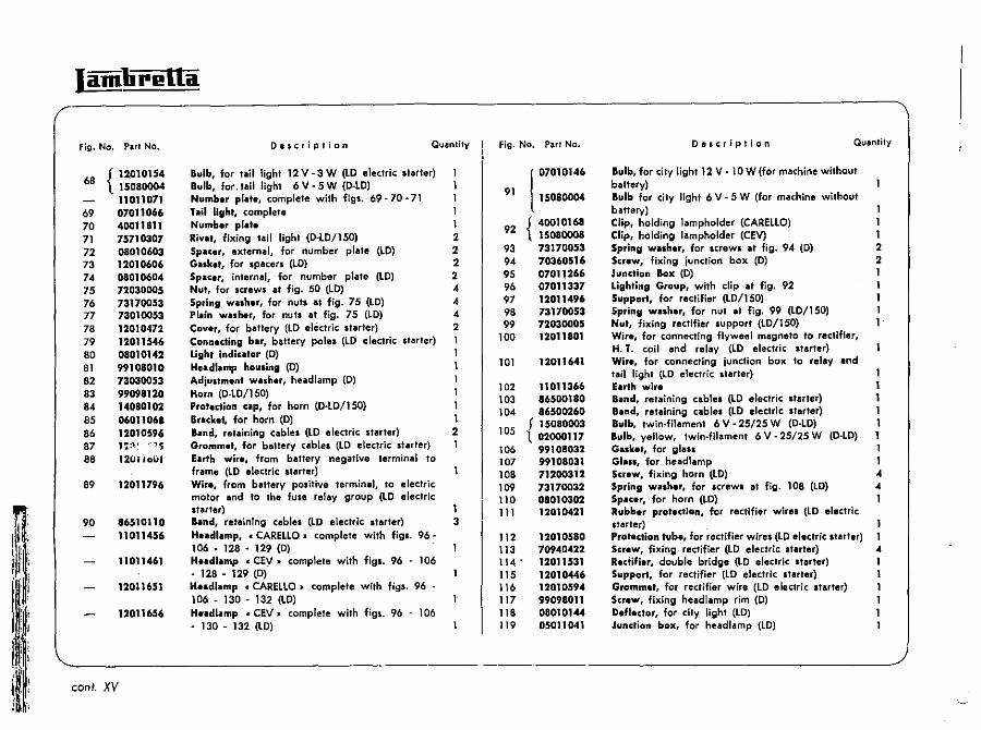
68 f 1~10154 1 15080004
11011071 69 07011066 70 40011811 71 75710307 72 08010603 73 12010606 74 08010604 75 72030005 76 73170053 77 73010053 78 12010412 79 12011546 80 08010142 81 99108010 82 73030053 83 99098120 84 14080102 85 06011068 86 12010596 87 1'0" '"1'5
8S 120.101.11
89 1201179,
90 8651Qll0 11011456
11011461
12011651
12011656
Description QUlJnlily
Bulb, for taillight 12V-3W (LO electric starter) 1 Bulb, for. tail light 6 V - 5 W (D-lD) 1 Number pl.t., complete with figs. 69 - 70 ·71 1 TiJlil light, complete 1 Numb.r pla.e 1 Riye., fixing tail light (D-lD/ISO) 2 Spacer, external, for number plate (LD) 2 Galket, for Ipacers (LD) 2 Spacer, internal, for number plate (LO) 2 Nut, for screws at fig. 50 (LO) 4 Spring walher, for nuts at fig. 75 (LO) 4 Pl.iin washer, for nuts at fig. 75 (LO) 4 C;over, for battery (LD electric starter) 2 Connecting },ar, battery poles (LO electric starter) Light indicator (D) Headlamp housing (D) Adiustment washer, head lamp (D)
Horn (0-LD/150) Protection cap, for horn (D-tD/150) I Bracket, for horn (D) I Iillnd, retaining cablel (LD electric starter) 2 Grommet, for battery cablel (to electric starter) Earth wit •• from battery negative terminal to frame (lO electric starter) Wir., from battery positive terminal, to electric motor lind to the fuse relay group (LO electric starter) 1 land, retaining cablel (LO electric Itarter) 3 Heilldlillmp. c CARElLO. complete with figl. 96-106 • 128 • 129 (0) Heilldlamp c CEV. complete with figs. 96 - 106 • 128 • 129 (0) Headlamp c CAREllO. complete with figs. 96 -106 • 130 • 132 (lO) H.adlamp c CEV. complete with figs. 96 • 106 • 130· 132 (lO)
fjg. No. Pari No.
(
07010146
91 15080004
92 {4oo10168 15080008
93 73170053 94 70360516 95 07011.266 96 07011337 97 12011496 98 73170053 99 72030005
100 12011801
101
102 103 10'
105
106 107 108 109 110 111
112 113 114 • 115 116 117 118 119
12011641
11011366 86500180 86500260
f 15080003 1 02000117
99108032 99108031 71200312 73170032 08010302 12010421
12010580 70940422 12011531 12010446 12010594 99098011 08010144 05011041
Description Quantity
Bulb, for city light 12 V· 10 W (for machine without battery) Bulb for city light 6 V - 5 W (for machine without battery) 1 Clip, holding lampholder (CARELLO) I Clip, holding lampholder (CEV) 1 Spring wash.r, for screwl at fig. 94 (D) 2 Screw, fixing junction box (D) 2 Junction Box (0) I Lighting Group, with clip at fig. 92 1 Support, for rectifier (lO/150) 1 Spring walh.r, for nut at fig. 99 (LD/150) Nut, fixing rectifier lupport (LO/150) Wir., for connecting flywcel magneto to rectifier, H. T. coil and relay (LO electric starter) Wir., for connecting junction box to relay and tail light (LO electric Itarter) 1 Earth wire 1 Band. retaining cablel (LO electric Ilarter) 1 Band, retaining cables (LO electric Itllrter) I Bulb, twin-filament 6 V - 25/25 W (O-LO) t Bulb. yellow, 1win·filament 6 V - 25/25 W (D·LD) 1 Galk.t, for glass 1 Glass, for headlamp I Screw, fixing horn (LD) 4 Spring walher, for screwl at fig. 108 (LD) .. Spacer, for horn (LD) 1 Rub},er protectionj for rectifier wlrel (LO electric Itarter) Protection tube, for rectifier wires (LO electric Itarter) Screw, fixing rectifier (LO electric Itarter) 4 Rectifier, double bridge (LO electric Itarter) 1 Support. for rectifier (LO electric Itarter) I Grommet, for rectifier wire (LD electric Itarter) I Screw, fixing head lamp rim (0) 1 Deflector. for city light (LO) 1 Junction box, for headlamp (LO)
'------------------------------------------------------~ coni. XV
UWMtNI~ ELECI KII.AL tl,l /1 956 - LD/1956 lU/LlJ ELECTRIC STARTER) Section XV
'NNllceNT.
~I:· ,III! 111 :
Jamlirella
Fig. No. Part No.
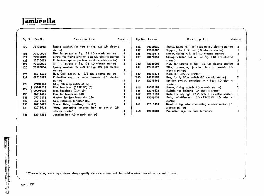
120
121 122 123 124 125
126 127
128
129
130 131 132 133 134
135
73170043
72030004 10910312 12010463 72U30006 73170064
12011576 08010529
99108033
{ 99t08016 99098002 08011406 05010113 05010131 70910412 12011636
12011556
Description Quantity
Spring washer, for nuts at fig. 121 (to electric starter) Nut. for screws at fig. 113 (LD electric starter) Screw, for fixing junction box (tD "electric starter) Prot,clion up, for junction box (lO electric starfer) ~t.., '. " .(rewa at fig. 138 (LO electric starter) Spring washer. for nuts at fig. 124 (lO electric starter) H.1. Coil, Boscn, TJ 12/3 (LO electric starler) Prot.ction elp. for wires termInal (lO electric starter) Clip, retaining reflector (D) Rim, head lamp (CAREllO) (D) Rim, headlamp (U. Vj (D) Rim, for head lamp (LD) Guket, for headlamp rim (to) Clip, retaining reflector (LO) Scraw, fixing head lamp rim (to) Wir.. connecting junction box to switch (LD electric Jtarler) Junction box (lO electric starter)
4 4 2 I 2
2 I
2 4 I
4 I
Fig. No. Part No.
136 137 138 139
140 141
142 *143
144
145 146 147 148
149
150
70300550 12010586 10850616 13170053
72030005 12011626
12011571 15081037 12011566
99098104 12011621 12010153 12010152
12010451
12010304
Description Quantity
Screw, fixing H. T. coil support (lO electric starter) Support. for H:T. coil (LD electric slarter) Screw. fixing H. T. coil (lO electric starter) Spring w •• her, for nut at fig. 140 (LD electric darter) Nut, for screws at fig. 136 (LD electric stiJrter) Wire, connecting junction box to switch (LD electric starter) Horn (lO electric starter) Key, for ignition switch (lO electric starter) Ignition switch. complete with keys (LD electric starter) Screw, fixing switch (lO electric starter) Switch. for lighting (lO electric starter) Bulb, for city light 12 V • 5 W (LD electric starter) Bulb. twin·filament 12 V· 25/25 W (LD electric starter) B.nd. fixing wire connecting electric motor (lO electric starter) Protection up, for horn terminals.
2 I 2
2 2
I 2
I 2
111 !I~' ).'I~~i: . When ordering spare keys, pleue always specify the manufacturer and the serial number stamped on the swjtc~ ba$e.
l I, i, iii! conI. XV ',\.Ii ,lIn'
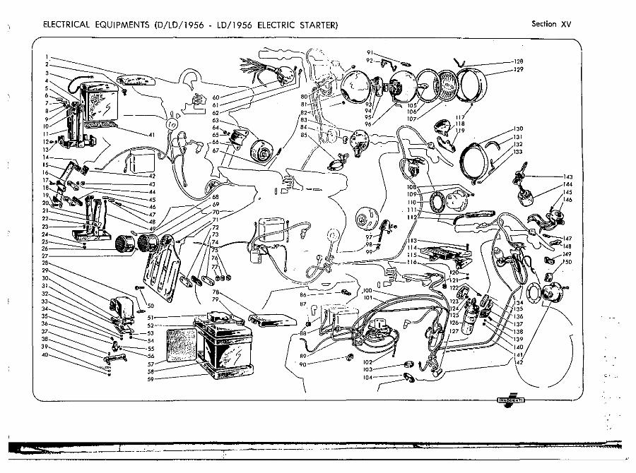
ELECTRICAL EQUIPMENTS (D/LD/1956 - LD/1956 ELECTRIC STARTER) Section XV
.. '.:..
I amli rl! lla
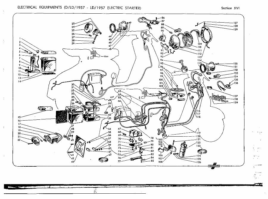
Fig. No. ParI No.
{ 11010466 19081032
2 14080102 3 15081029 4 70880430 5 15081031 6 11011177 7 70850406 a 73170043 9 71360512
10 12011201 11 73170053 12 72030005 13 19081170 14 11010558 15 12010472 16 12010468
12011821 12090384
17 12010611 18 12011826 19 12011831
I 08010605 20 12010154
15080004 21 12010610 22 19083005 23 72030006 24 73170064 25 15081250 26 87200005 27 12011496 28 73170053 29 72uJui)05 30 70880430
Oe,cription Quantity
Cover, for battery (SCA1NI) (LO/ISO) Cover, for battery (FlAMM) (lO/ISO) Prolection cap, for battery terminal (LD/150) thr.ad.d trunnion (LD/ISO) Screw, for strap retaining battery (lO/ISO) 1 Bored trunnion (lO/ISO) 1 Earth wir., for battery (LO/ISO) 1 Screw, Jocking earth wire (LD/150) 1 Spring washer, for screw at fig. 7 (lO/150) I Screw, fixing battery support (lO/150) 2 Support, for battery (LD/150) 1 Spring willher, for nuts at fig. 12 {lO/lSD} 2 Nut, fixing battery support (lO/lSO) 2 BilIltuy, complete with fig. 1 (LD/1SD) 1 hit, for battery (lO/lSD) 1 Cover, for battery (lSD/LD electric starter) 2 Felt, battery (lSO/LD electric starter) 1 lillil light, complete with figs. 18·19·21·22 1 hi! light, with stop light, complete with figs. 18 . 19 • 21 • 22 Gillkel, for tail light Body, for tail light lamp holder Lampholder Bulb,6V-I,5W (LO/150) Bulb, 12 V • 3 W (LO/lS0 electric starter) Bulb, 6 V - 5 W (LO/125) Red gem Screw, fixing red gem 2 Nut, fixing rectifier (lO/ISO) 1 Spring walher, for nut at fig, 23 (LD/lS0) Rectifi.r (LD/1SD) Fu.e, for rectWer 5 Ampere (lO/150) Bracket, for rectifier (lO/ISD) Spring wa.her, for nut at fig. 29 (LD/15D) Nut, for fixing rectifier br"cket (lO/150) Screw, fixing battery ,'r<llp (lO electric Itarter)
Fig, No. Part No.
31
32
33
34
35 36
37 38 39 40 41 42 43 44 45 46 47 48 49
50 51 52 53
54 55 56 57 58 59 60
15081031
150B1029
12010459
12011546
12011521 12010469
12010609 73010053 73170053 72030005 7102052B 70910512 12010608 08010302 12010304 12011731 73170032 71200312 08010529
12011861 12010526 70450508 73170053
12011771 73170053 72030005 08010604 73010053 73170053 72030005
De,cr(ption Quantity
Bored trunnion, for battery .trap (lO electric .tarter) Thruded trunnion, for battery strap (lD electric starter) Elastic support, for battery pole. (LD electric starter) Connecting bars, for battery poles (LD electric starter) 1 Battery (LO electric starter) 2 Rubber ring, connecting battery (LO electric starter) i Bar, fixing tail light 1 Plain washer, for nut. at fig, 40 2 Spring washer, for nuts at fig. 40 2 Nut, fixing tail light 2 Screw, for fixing number plate (lower p<llrt) 2 Screw, for f~xing number plate (upper ptlft) 2 Number plate 1 Sp.cing ring 1 Protection cap, for horn cable (lD/12S·1S0) 1 Horn (12S·1S0/LD) I Spring wesher, for screw~ al fig. 48 .. Screw, fixing horn 4 Protection cap. for battery terminal (LO electric st<llrler) 2 Support,. for battery (LD electric starter) 1 Grommet, for electric wires, (lO electric starler) 1 Screw. fixing battery .upport (lO electric .tarter) -4 Spring wa.her, for acrew.' at fig. 52 (lO electric starter) 4 Earth wire, for tail lamp 1 Spring wa.her, for I~uts at fig. 56 2 Nut. for .crew. at fig. 42 2 Slack, Internal, fixing number plate 1 plain wa.her, for nutl at fig. 60 2 Spring wa.her, for nuts al fig. 60 2 Nut, for screw. at fig. 41 2
~~ ____________________________________________________ J XVI
'.
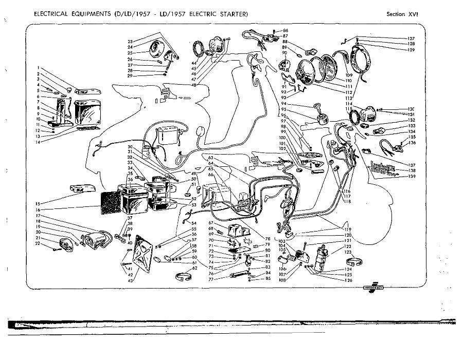
ElECTRICAL EQUIPMENTS (D/lD/1957 - LD/1957 ElECTRIC STARTER)
~;~~ 26 __ ~ 27 2. • 29 Ell
Section XVI
127 2.
131 32
,. '--__ =-""'--139
©62 t---83 --= .4 __ ci£$f;l~ 85
77 e-~. _______________________ ~~ ____________________________________________________________ ~,~""~o.~'~"'D'-----------
-;.
Iamlirl!lla
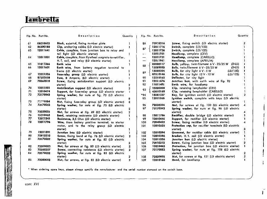
Fig. No. Part No.
61 62 63
64
65 66
67 68 69
70 71 72
73 74
75 76 77 78
79 80 81
82 83 84
85
08010603 86500180 12011641
12~11801
11011366 12011601
12011526 87200008 70360510
12011501 12010474 73170043
7:;:1'10004 73170053
72030005 1:;:010465 12011541 12011796
12011591 70910310 73170032
72000001 70360307 73170032
72000003
Description Quantity
Block, external, fixing number plate Clip, anchoring cables (lO electric starter) Ciilbl., complete, from junction box to relay and tail light (LO electric starter) C .. bl., complete. from flywheel magneto to rectifier, H. T. coil, and relay (LO electric starter) E'llrth wire Euth wir., from battery negative terminal to frame (lO electric starter) Fus.-rlilllilY group (LO electric s,arler) Fuse, 8 Ampere, (LO electric slarter) Scrow, fixing antivibration support (lO electric starter) 2 Antivibriltion support (LO electric starter) 2 Support, for fuse-relay group (lO electric starter 1 Spring wllh.r, for nuts at fig. 73 (LO electric starter) 8 Nut, fixing fuse-relay group (LD electric starter) 8 Spring washer, for nuts at fig. 75 (LD electric starter) 2 Nut, for screws at fig. 69 (LD electric starter) 2 Band, retaining resistance (LD electric starter) 1 Resist.-nce, 3,5 Ohm (LD electric starter) Wire, from battery positive terminal, to starter motor, and to the relay group (LD electric starter) Junction box (LD electric starter) Screw, fixing band at fig. 76 (LD electric starter) 2 Spring wash.r, for nuts at fig. 82 (LD electric starter) 2 Nut, for screws at fig. 80 (LD electric starter) 2 Screw, connecting resistance (LD electric starter) 2 Spring washer, for nuts at fig. 85 (LD electric starter) 2 Nut, for screws, at fig. 83 (LO electric starter) 2
fig. No. Part No.
86 70910316
{ 12011716
87 12011726 12011701 12011721 12011961
88 t 02000117 1508ooD3
89 15080004 07010146
90 12010165 91 12011676 92 11011481
93 {1508ooo8 40010168
*94 15081037 95 12011566
96 72030004 97 73170043
98 12011786 99 12010446
100 70940422 101 12010525
102 12010594 103 12010586 104 12011556 105 70910312 106 12010463 107 73170053
108 72030005 109 12010160
Description Quantity
Screw, fixing switch (LD electric starter) 2 Switch, complete (LD/150) Switch, complete (LD/125) Heildlilmp, complete (CEV) Hudlilmp, complete (CARELLa) Hfladlamp, complete (APRILlA) Bulb, yello":,, twin·filament 6 V - 25i25 W (D-LD) Bulb, twin_filament 6 V - 25/25 W (D-LD) Bulb, for city light 6 V - 5 W (LD/150) Bulb, for city light 12V-10W (LD/125) Deflector, for city light Junction box, with earth wire at fig. 92 Eilrth wire, for head lamp Clip, retaining lampholder (CEV) 1 Clip, retaining lampholder (CARELLa) 1 Key, for ignititon switch (LD electric starter) 2 'gnition switch, complete with keys (LD electric starter) Nut, for screws at fig. 100 (LD electric starter) 4 Spring washer, for nuts at fig. 96 (LD electric starter) 4 Rectifier, double bridge (LD electric starter) 1 Support, for rectifier (LD electric starter) 1 Screw, fixing rectifier (LD electric starter) 4 Protection cap, for rec,-ifier terminals (LO elecltric slarter) 3 Grommet, for rectifier cable (LO electric sti!lrter) 1 Bracket, H. T. coil (LD electric starter) 1 Junction box (lO electric starter) 1 Screw, fixing junction box (LD electric starter) 2 Protection, for junction box (LO electric starter) 1 Spring wilSher, for null at fig. lOa (LD electric starter) 2 Nut, for screws at fig. 121 (LD electric starter) 2 Hood, for headlamp 1
• When ordering spare keys, please always specify the manufacturer and the serial number stamped on the ,witch base.
coni. XVI
ELECTRICAL EQUIPMENTS (D/LD/1957 - LD/1957 ELECTRIC STARTER) Section XVI
~~,""'===--1130 31 32
/ ,Q \
~/. , "
~62
... ---- C; .. "'-o;!.,r,;-!E"f-------'
1
Iamlirl!lta
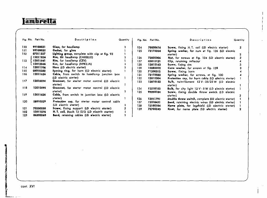
Fig. No. Part No.
110 99108031 111 99108032 112 07011337
(
12011836 113 12011841
12012046 114 12011706 115 08010302 116 12011636
117 12010594
118 12010595
119 12011626
120 08010529
121 70300550 122 12011576 123 86500260
coni, XVI
D.scription
Ght;lS, for headlamp GilSket, for glass Lighting group, complete with dip at fig- 93 Rim, 'fOr head/amp (CAREllO) Rim, for head/amp (CEV) Rim, for head/amp (APRllIA) Horn (LO electric starter)
Quantify
Spacing ring, for horn (Lo electric starter) Cable, from switch to headlGmp junction box (lo electric starter) Grommet, for starter motor control (Lo electric starter) Grommet, for starter motor control (Lo electric starter) C.ble, from switch to junction box (LO electric starter) Protection up, for starter motor control cable (lo electric starter) 1 Screw, fixing support (LO electric slarter) 2 H. T. coil, Bosch TJ 12/3 (LO electrit: starler) 1 aand, retaining cables (lo electric starter) 1
Fig. No. Part No.
124 125
126 127 128 129 130 131 132 133
134 135
136 137 138 139
70850616 73170064
72030006 05010131 12010163 15080002 71200312 73170032 12010304 12010152
12010153 99098104
12011791 12010451 12180184 75700245
Oescription Quantify
Screw, fixing H. T. coil (to electric starter) 2 Spring Wlishlr, for nuts at fig. 126 (LO electric starter) 2 Nut, for screws at fig. 124 (LO electric starter) 2 Clip, retaining reflector 4 Screw, fixing rim 3 Cone wlsh.r, for screws at fjg. 128 3 Screw, fixing horn -4 Spring wllher, for screws, at fig. 130 4 Profeclion ClIp, for horn cable (lO electric stiuter) 1 Bulb, twin-filament 12 V - 25/25 W (LD electric starter) Bulb, for city light 12 V - 5 W (lO electric starter) Screw, fixing double throw switch (LO electric stllrter) 2 Double throw Iwitch, complete (LO electric Itarter) 1 a.nd, retaining electric wires (lo electric starter) 1 N.m. pl ••• , for legshield (lO electtric stllrter) 1 Rive" for name plate (LO electric starter) 2
,,··,S
ELECTRICAL EQUIPMENTS (D/LD/1957 " LD/1957 ELECTRIC STARTER) Section XVI
~:~~~". '6~~ 27 ,. . 29 It
.---------------------------~~.~".~,,~"'m,~------
c
Iamlirl!Ua
Fig. No. Part No.
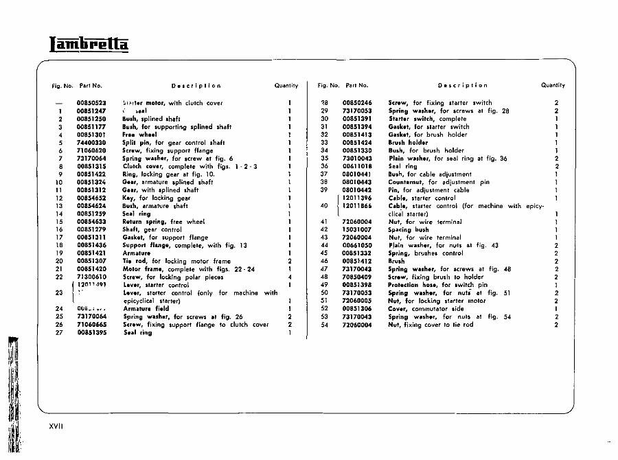
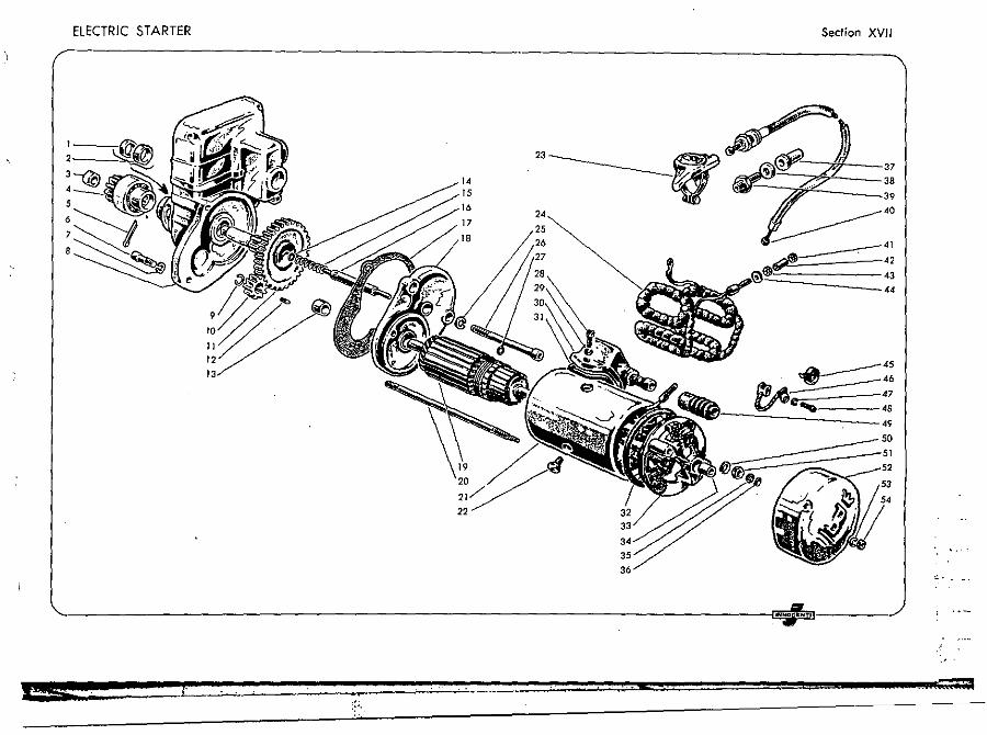
1 2 3 4 5 6 7 8 9
10 11 12 13 14 15 16 17 18 19 20 21 22
23
24 25 26 27
XVII
00850523 00851247 00851250 00851177 00851301 74400330 71060620 73170064 00851315 00851422 00851324 00851312 00854652 00854624 00851259 00854633 00851279 00851311 00851436 00851421 00851307 00851420 71300610
f !?nn ·101
\ Otlti~; "" 73170064 71060"5 00851395
Description QUilinlily
~i.~!I.r motor, with clutch cover ~ .. I
Rush, splined shaft Bush, for supporting splined shaft Fr .. wh •• 1 Split pin, for gear control shaft Screw, fixing support flange Spring w •• h.r. for "rew at fig. 6 Clutch cover, complete with figs. 1 - 2 - 3 Ring, locking gear at fig. 10. G •• r, armature splined shaft Gu" with splined shaft Key, for locking gear Bush, armature shaft Seel ring R.turn spring, free wheel Shift, gear control Guket, for support flange Support flange, complete, with fig. 13 Armature Tie rod, for locking motor frame Motor fr .. me, complete with figs. 22·24 Screw, for locking polar pieces Lever, starter control Lever, starter control (only for machine with epicyclica1 starter) Armature field Spring w .. sher, for screws at fig. 26 Screw, fixing support flange to clutch cover Seal ring
1 1 1 1 2 1 4 1
1 1 2 2
Fig. No. Pilirl No.
.8 29 30 31 32 33 34 35 36 37 38 39
40
41 42 43 44 45 46 47 48 49 50 51 52 53 54
00850246 73170053 00851391 00851394 00851413 00851424 00851330 73010043 00611018 08010441 08010443 08010442
r 12011396 ll2011866
72060004 15031007 72060004 00661050 00851332 00851412 73170043 70850409 00851398 73170053 72060005 00851306 73170043 72060004
Description Quantity
Screw, for fixing starter switch Spring w .. sh.r, for screws at fig. 28 Starter switch, complete GoUket, for starter switch GoUket, for brush holder Brush holder Bush, for brush holder Plain washer, for seal ring at fig. 36 Seal ring Bush, for cable adjustment Count.rnut, for adiustment pin Pin, for adjustment cable C .. ble, starter control Cable, starter control (for machine with epicy· dic~1 starter) Nut, for wire terminal Spacing bush Nut, for wire terminal P,lain washer, for nuts at fig. 43 Spring, brushes control Brush Spring w.sher, for screws 011 fig. 48 Screw, fixing brush to holder Protection hose, for switch pin Spring wuher, for nuti at fig. 51 Nut, for locking starter motor Cover, commutator side Spring wuher, for nuts at fig. 54 Nut, fixing cover to tie rod
2 2 1 1 1 1 1 2 2 1 1
1 2 2 2 2 2 1 2 2 1 2 2
ELECTRIC STARTER Section XVII
22
,.:.
,;;
lamlirl!lla
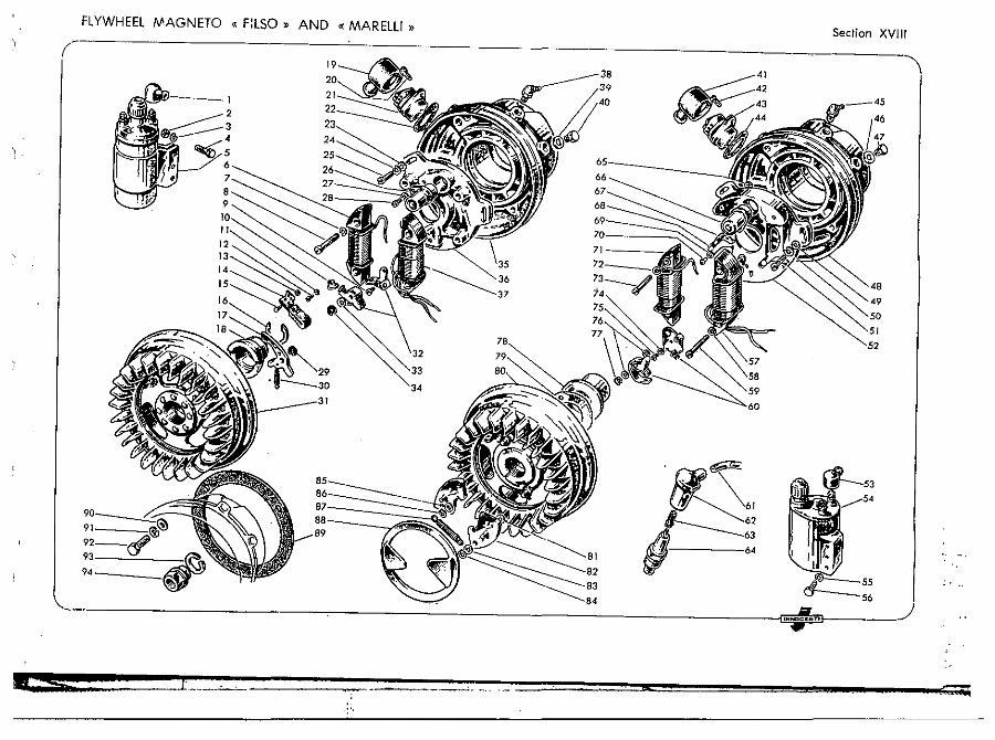
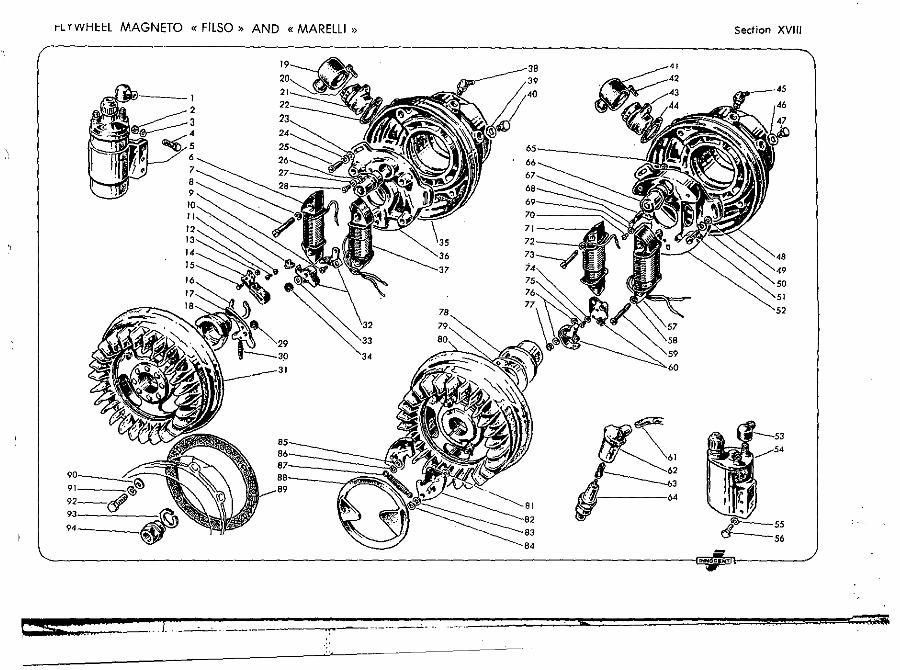
Fig. No. Part No.
00831586 MVB 4 E
1 11010511 2 72030004 3 73170043 4 70300414
r, .j1579 B 101 E 5 } 12011081
00831549 MVB 4/25-B 6 l 00831526 MVB 4/25·A 7 73170053 8 00831423 90012/171 9 00831437 9508&-1
10 00831482 AVS2/41D-l 11 00831424 90024-3
12 00831461 90010..131 13 00831522 90022·51 14 00831410 MVA21/12-A 15 00831431 90034-221 16 00831555 MVB 4/521·1 17 00831589 MVB 4/55 C 18 00831588 MVB4/520-2 19 99098221 20 71200410 21 11011231 22 11010515 23 73030053 24 73170053 25 70850518 26 00831521 CE 4 H 27 00831426 90024-5 28 00831462 90028·31 29 00831558 9007~
30 00831557 MVa 4/522-1 31 00831587 MVB 4/52-B
XVIII
Description Quantity
Flywheel millgn,to, • Matalli)O (without flange at fig. 35) Protedion cup, H. T. coil terminals Nut, for screws fixing H. T. coil Spring wiI,h.r, for nuts at fig. 2 Screw, fixing H. T. coil H. T. coil H. T. coil, Bosch, TJ 6/6 (lD/150) L. T. ignition coil (D.lD/150) L. T. ignition coil (LO/125) Spring wilshar, for screws lit fig. 8 Screw, fixing coils Screw, fixing contact points at fig. 32 Insuliilling block, conlact breaker arm Spring w,uh.r, for screw fixing breaker /lrm connection Scr.w~ for fixing breaker arm connection Protection wilsh.r Gr •• ser pild, for cam aivel, fjxing greaser pad eirelip, retaining cam Bob weight C.m Protection cup, L. T. socket Screw, fixing L. T. socket L. T. lock,t G.uke., for l. T. socket PI.in w,lIh.r, for screws at fig. 2S Spring w.sher, for screws at fig. 2S Screw, fixing stator plate Condenser . Spring washer, for screw at fig. 28 Screw, locking condenser Circlip, retaining bob weight Return spring, bob weight flywhe.I, complete with figs. 16 - 17 --18-29-30
2 3 3 3 1 1 1 1 4 4 1 1
1 1 1 2 1
1 3 3 3 1
Fig. No. Pl:lrt No.
32 00831611 {AVS2/4G-D AVS2/41·A
33 00831574 90058-301 34 00831460 N. 1853/4 3S 11110113 36 00831590 37 r 00831551
l 00831584 38 87030008 39 14010014 40 11110112
MVA21/1l-D MVB 4/30-C MVB 4/3().D
00811413 C.12336
00811426 C 12340
41 99098221 42 71200410 43 11011231 44 11010515 45 87030008 46 14010014 47 IllI0112 48 11110113 49 73030053 50 73170053 SI 70850518 52 00811352 E 12045 53 11010511 54 00811384 C.12128/1 55 73170043 56
57 {
58 59
70360410 00811359 00811390 00811396 00811345 00811360
C.12048 C.12159 C.12167/1 20418/5.3 20018/5 x 34
Description Qualllily
Conled points
Shim, for contact points Circlip, retaining contact points flang., flywheel magneto Stator plili. L. T. lighling coil (D-LO/150) 1. T. lighting coil (LO/12S) Gr.as. nippl., for crankshaft bearing Gask.t, for breather plug Breillther plug flywheel magn.to • Filso. (without flange at fig. 48 (LO electric starler) Flywheel magneto • Filso. (without flange at fig. 48 (LO electric starter) Prolection cap, l. T. socket Screw, fixing l. T. socket L. T. socket Gasket, for L. T. locket Gr.ase nippl., for crankshaft bearing Gal~.t, for breather plug Br ••• h.r plug Flinge, flywheel magneto Plain wash.r, for screws at fig. 51 Spring w.sh.r, for Icrews, at fig. 51 Screw, fixing Itator plate Stator pl.te Protedion cup, H. T. coil terminals H. T. coU Spring wlSh.r, for Icrews, at fig. 56 Screw, fixing H. T. coil 1. T. lighting coil (0-10/150) 1. T. lighting coil (LD/125) 1. T. lighting coil (LO electric ,tarter) Tel, wash.r, for screws at fig. 59 Scr.w, fixing L. T. lighting coil
1 1 3 3 3
2
1 3 3 1 1 1 2 2
FLYWHEEL " (_ "AGNETO « F:LSO» AND «MARELLI "
....
'~::S61 ~~62
.. /,i 63 6'
Section XVIII
; ..
-+
Iamlirl!lla
Fig. No. Part No.
60
61 62
63 64 65 66 67 68 69 70
71 \
72 73 74 75 76 77
00811432 J c. 11509/1 \ C. 10894/2
12010507 15017070
15017012 14010701 7200000S 00811356 1.12009 00811353 E. 11803 00811284 E. 112S2/R 1 00811339 N.246/3 00811380 20037/3 x 5 00811346 C.11978 00811400 C.12211/1 00811395 C.12168/1 00811345 20418/5,3 00811355 20018/5x28 00811288 20403/4,3 00811354 20017/4 x 8 00811313 N.116/1 00811312 N.235
conI. XVIII
Description Quantity
Contact points
H. T. r.ad C.p. for spark plug with screw at fig. 63 ~cr.w, for fjxing H. T. lead Spark plug Nut. for screws, at fig. 59 - 73 Condenser G'!lilser box Gr • .,.r pad Spring washer. for screw at fig. 70 Screw, for fixing condenser L. T. ignition coil (D-lD/150) L. T. ignition coil (lD/125) L. T. ignition coil (LD electric starter) Tilb w.uh.r, for screws at fig. 73 Screw, fixing L. T. coil Plain wilSher, for screw at fig. 75 Screw., fixing items at fig. 60 Insulilling washer, for contact points Cirdip. locking contact points
1 1 4 1 1 1 1 1 1 1 1 2 2
1 2 1
Fig. No.
78 79
80 I 81 82 83 84 85 86 87 88 89
90 91 92 93 94
Pari No.
00811362 C.12033/1 00811363 E.12044/1 00811414 C.12335/1
00611427 C.12339/1
00811366 N.116/45 00811368 C.12057/1 00811371 N.116/76 00811372 247/bis/6 00811364 N.116/75 00811365 247/bis/S 00811370 C.12063 00811374 E.12061 11110131
73030064 73170064 02110108 02110311 02110312
Description Quantity
C.m friction ring. for cam Flywh.el, complete with figs. 78 - 79 - 81 - 82 - 83 - 84 - 8S - 86 - 87 Flywheel, complete with figs. 78 - 79 - 81 - 82 . 83 . 84 . 85 . 86 . 87 (LD electric starter) PI"in wuhar, for bob weight pins Bob weight PI .. in wuher, for bob weight pins Circlip, for bob weight pins PI "in wilSher, for cam pins. Cirdip, for cam pins Return spring, bob weight Plntic shock .. bsorbing ring G .. sket, between crankcase/magneto flange Plilin wnher, for screws at fig. 92 Spring wnher, for screws. at fig. 92 Screw, fixing flywheel magneto flange Spring wnh.r, for nut at fig. 94 Nut, for locking flywheel magneto
1 2 2 2 2 4 2 1 1
6 6 6 1
rLY WHttl MAGNETO «FllSO» AND «MARElli » Section XVIII
9'---_t.:
IH",OCII:HTI
54 ;; J .. ....
Fig. No. Put No.
1 2 3 4 5 6 7 8 9
10 11 12 13 14 15 16
17 18 19 20 21 22 23
"24 25 26
27 28 29 30 31 32
12181081 72030005 73170053 70910510 73170053 70910508 15055044 15055047 15055045 15055042 15055043 74400330 15055046 15055048 05180201 12090368
12180269 12180247 73010043 72090004 12181336 08181241 12181426 15055056 12181371 12181366
12180228 12180248 15086015 12180224 12180223 121'0226
Description Quantity
Mudgu.rdl rear Nut, for screws at fig. 4 Spring wa.h.r, for screws at fig. 4 Screw, fixing rear mudguard Spring washer, for .crew. at fig. 6 Screw, fixing rear mudguard Bush, for panel lock Clip, for panel cup lock Cup, retaining .pring Pressure .pring, for panel lock Cup, retaining .pring Split pin, for panel lock Protection cap, for panel lock Grub, locking handle Hindle, for R. H. lock Lock R. H., complete with figs. 7 - 8 . 9 - 10 11 - 12 - 13 - 14 - 15 Grill, for panel (suitable for the old panels) Screw, for fixing grills to the old panels Plain washer, for screw. at fig. 18 Nut, for screws at fig. 18 Pinel R. H. Mit, footboard R. H. Footboud R. H. Key, for luggage box lock Lock, with keys Lid, luggage box, with lock at fig. 25 (LD epicyclical .tarter) ae.ding, luggage box lid Spring, fixing fool bag Pllte, for spring Pin, IU9gage box hinge Tube, for lid hinge Tube, retaining lid spring
1 2 2 2 2 2 2 2 2 2 2 2 2 2 1
1 2 8 8 8 1 1 1 2
Fig. No. Part No.
33 34
35 36 37
38
39 40 41 42 43 44 45 46 47 48 49 50
51 52 53 54 55 56 57 58 59 60 61 62
12180225 12180264
73170064 73170053 72000005
{ 12181321 12181461
12180271 72030008 12181331 08180222-71450425 08180142 05180172 72030004 12770231 12770232-05180202 12090367
12181421 12180195 08181046 08181246 71420418 08180175 19050098 08180144 08180140 08180145 70910512
'73170053
Description Quantity
Return spring, luggage box lid Bolt, fixing battery cover n. 12181321 (LD electric starter) I Spring w.sher, for .crew at fig. 34' 1 Spring wllher, for nub at fig. 37 8 Nut, for fixing bootboards 8 Cover, for battery box (LD electric .tarter) Cove" for battery box (for frame with air Intake in the luggage box) (LD electric starter) Pin, for battery cover n. 12181461 2 Nut, for pin at fig. 39 2 P.nel L. H. 1 Buding, for panel 2 Screw, for fixing end caps 4 End cap 12 Spring Wisher, for screws at figs. 43·55 t-Nut, for screws at fig.. 43 - 55 6 Protection, for cables (LD/125) 1 Protection, for cable. (LD/I25) Hindle, for L. H, lock Lock, L. H. complete with figs. 7 - 8 - 9 - 10 . 11-12-13-14-49 1 Leglhield 1 Rubber plug, for legshield 1 Footboillrd L. H. 1 Mit, for L. H. footboard 1 Screw, for fixing end cap. 2 Screw, for fixing beading channel 6 EI ... tic nut, for screws at fig. 56 6 anding chlnnel, inner 2 ae.ding, for footboard 6 Beading ch.nnel, outer and intermediate .4 Screw, fixing legshield and junction box to frame 2 Spring washer, for screws at fig. 61 2
• Wh'ln ordering spilte keYI, pleille alwavs specify the milnufacturer and the seri"l number ,hmped on the lock base.
XIX
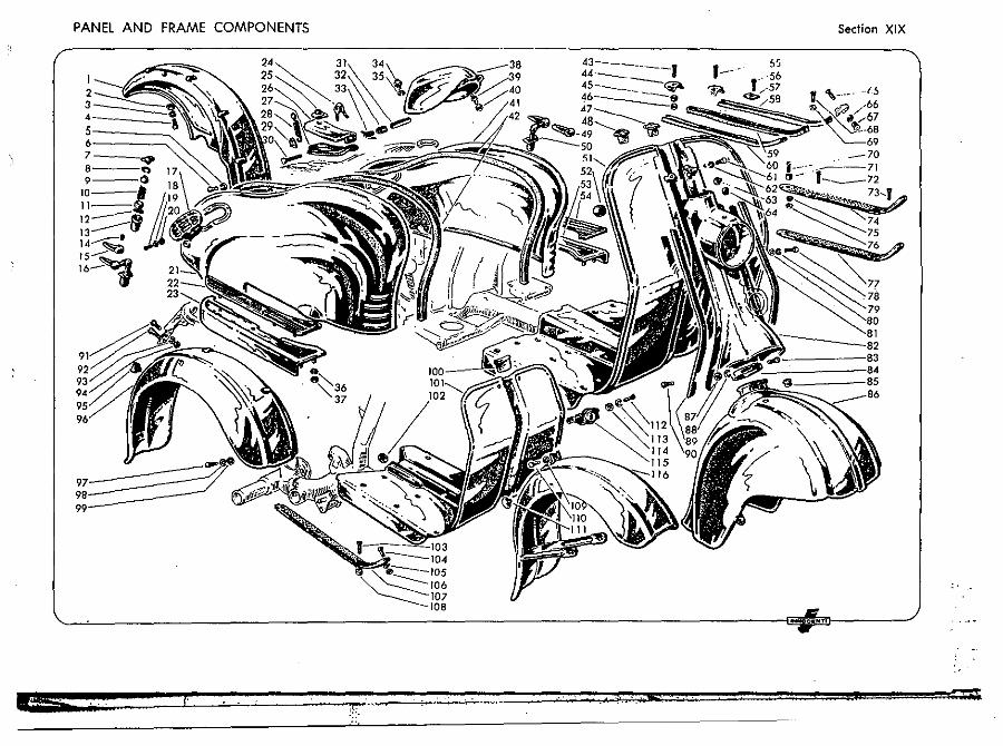
PANEL AND FRAME COMPONENTS
7 __ _
~==() 10----. II--!i 12-----8 13 _______ lJ' 14"-':::-' IS---~ IV~
Section XIX
~.~~ _______________________________________ ~~~.~".m' __ --~
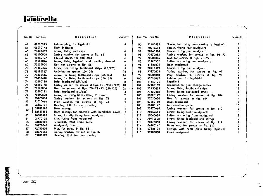
Iamlirl!lla
Fig. No. ParI No.
63 64 65 66 67 68 69 70 71 72 73 74 75 76 77 78 79 80 81
82
83 84 85 86 87 88 89
08010913 08010142 71420409 83100006 12180137 19050096 72030004 7145o.t25 05180147 71420416 71450428 12180190 05180172 72030004 12180191 70300620 73170064 73010064 05180171
{ 08181286 12181386 70300520 05770125 03180109 08771046 72030005 73170053 05180170
Description Ql,lantity
Rubber plug, for legshield 4 Light indiCAtor 1 Screw, fixing end caps 6 Spring WAsher, for screws at fig. 65 6 Specjal screW, for end caps 6 Screw, fixing legshield and bellding channel 6 Nut, for screws at fig. 68 6 Screw, for fixing footboard strips (LD/125) 4 Antivibr.tion spacer (LO/125) 18 Screw, for fixing footbollrd strips (LD/125) 14 Screw, for fixing footboord strips (LD/125) 6 Strip, footboard (LD/125) 2 Spring washer, for screws at figs. 70 - 72 (LD/125) 18 NUl, for screws at figs. 70-72-73 (LD/125) 24 Strip, footboard (LO/125) 4 Screw, for fixing horn casting to frame 2 Spring WAsher, for screws at fig. 78 2 Plain wash.r, for screws 'at fig. 78 2 ae.ding, L.H. for horn casting 1 Horn casting 1 Horn casting, for machine with handlebar cowl) I Screw, for clip fixing front mudguard 1 Clip, fixing front mudguard 1 Gromm.t, front brake cable Mudguard, front • Nut, for screw it fig. 83 Spring washer, for nut at fig. 87 B •• ding, R.H. for horn casting
Fig. No. ParI No.
90 91 92 93 94 95 96 97 98 99
100 101 102 103 104 105 106 107 108 109 110 111 112 113 114 115 116
71480512 70910514 70360518 73170053 72030005 11180302 11181021 70910512 73170053 73030053 99095062 11180130 07180)52 71450425 71420418 05180172 72030004 07180150 05180147 73170064 70360614 15060039 70910508 73170053 06180141 07181121 99106050
Description
Scr.w, for fixing horn casting to legshield Screw, fixing rear mudguard ScreW, fixing .rear mudguard Spring wnl},.r, for screws at figs. 91 - 92 Nut, for, screws at figs. 91 - 92 BuHer, _ anchoring rear mudguard Re,., mudguard Screw, fixing rear mudguard Spring washer, for screws at fig. 97 Plain washer, for screws at fig. 97 Rubber pad, for JegshieJd Lesshield Grommet, for gear change cables Screw, fixing footboard strips Screw, fixing footbollrd strips Spring washer, for screws at fig. 104 Nut, for screws at fig. 104 Strip, footboard Antiv;bralion spacer Spring washer, for screws at fig. lID Screw, fixing front mudguard Buffer, lInchoring front mudguard Screw, fixing legshield and stirrup Spring WAsher, for screws at fig. 112 Dome nut, for .crews at fig. 112 Stirrup, with name plate fixing legshield Front mudgUArd
Quantify
2 1 1 2 2 2 I 2 2 2
12 4 4 4 4
16 3 3 2 2 2 2 1 1
l~ _____________________________________ / coni. XIX
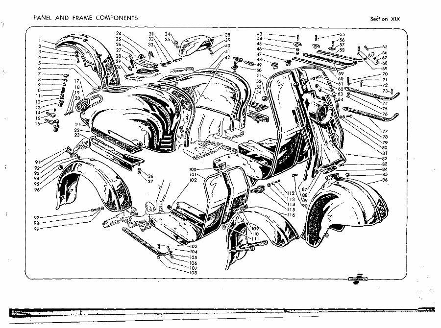
PANEL AND FRAME COMPONENTS
I 2 3
7_"" 8 .. I 9 () 10-' 11--2 J2----~ J 3..-------eJ 14""""""';:' J5---~ J6-~
INN CI(HT
Section XIX
77 78 79
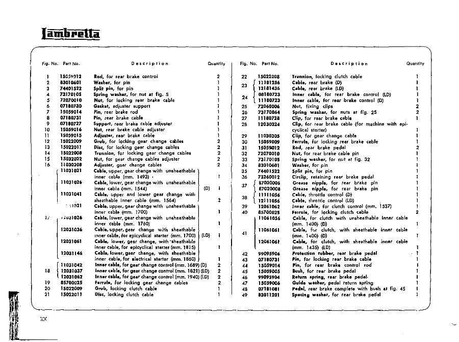
Iamlipl!lla
Fig. No. Pari No.
1 15C.!iVOI2 2 83010601 3 74401522 " 73170105 5 72070010 6 07180730 7 15059014 8 07180731 9 07180727
10 15059016 11 15059015 12 15022009 13 15022011 14 15022008 15 15032022 16 11030308
11031021
11031026
11031041
)~ 1021
Ii l.1u;,1026
12031036
12031061
12031146
(
11031042 18 12031037
12031062 19 85700025 20 15022009 21 15022011
xx
De$(riplion Quantity
Rod, for rear brake control 2 Washer, for pin 1 Split pin, for pin 1 Spring washer, for nut at fig. 5 1 Nut, for locking rear brake cable 1 Guket, adjuster support 1 Pin, rear brake rod 1 Pin, rear brake cable 1 Support, rear brake cable adjuster 1 Nut, rear brake cable adjuster 1 Adjustar, rear brake cable 1 Grub, for locking gear change cables 2 Disc, for locking gear change cables 2 Trunnion, for locking gear change cables 2 Nut, for gear change cables adjuster 2 Adjuster, gear change cables 2 Cable, upper, gear change with unsheathable inner cable (mm. 1493) , C.ble, lower, gear change with unsheathable inner cable (mm. 1544) (0) C.ble, upper and lower gear change with sheath able inner cable (mm. 1564) 2 C.bla, upper, gear change with unsheathable jnnE:f cable (mm. 1700) Cable, lower, gear change with unsheathable inner cable (mm. 1760) Cabl., upper, gear change with sheath able mner cab1e. for epicyclical starter (mm. 1700) (LD) C.bl •• lower, gear change, with "sheathable inner cable. for eplcyclical starter (mm. 1815) C.ble,lower,gear change. with sheathable inner cable, for electrical starter (mm. 1860) 1 Innar cable, for gear change control (mm. 1689) (D) 2 Innar c.ble. for gear change control (mm. 1821) (LD) 2 Inner cabla, for gear change control (mm. 1940) (lO) 2 ferrula, for locking gear change cables 2 Grub, locking clutch cable 1 Disc, locking clutch cable 1
Fig. No. Part No.
22 15022008
23
t 11181256 12181436 08180723
24 11180723 25 26 27 28
29 30 31 32 33 34 35 36
37
38
39 40
41
72060006 73170064 '1180728 12030324
11030305 15059009 15059012 72070010 73170105 83010601 74401522 73260012
I 61020006
{
87020008 11111056 12111056 12061062 85700025 11061056
11061061
12061061
42 99095906 43 07180731 44 15059014 45 15059005 46 99095904 47 15059006 48 07181011 49 83011201
Description Quantity
Trunnion, locking clutch cable 1 Cabl., rear brake (0) 1 C.bf., rear brake (LD) 1 Inner ubI., for rear brake control (LD) 1 Inner ubi., for rear brake control (0) 1 Nut, fixing dips 2 Spring wash.r, for nuts at fig. 25 2 Clip, for rear brake cable 1 Clip, for rear brake cable (for machine with epi-cyclical starter) 1 Clip. for gear change cable 1 F.rrul., for locking rear brake cable 1 Rod, rear brake pedal 2 Nut. for rear brake cable pin 1 Spring wash.r, for nuf at fig. 32 Wash.r, for pin Split pin, for pin Circlip, retaining rear brake pedal Greilu nipple, for rear brake pin Greils. nippl •• for rear brake pin Cable, throttle control (D) Cable, throttle control (lD) I Innar ubi., for clutch control (mm. T 537) 1 Ferrule, for locking clutch cable 2 Cable, for clutch with unsheathable inner cable (mm. 1400) (0) Cabl., f'"r clutch, with sheath able inner cable (mm. 1400) (D) C.ble. for clutch, with sheathable inner cable (mm. 1435) (lO) Protection rubber, rear brake pedal Pin, for locking rear brake cable Pin, for rear brake control rod Bush, for rear brake pedal Return Ipring, rear brake pedal. Guide wuher, pedal return spting ped.l, rear brake complete with bush at fig. 45 Spuin" washer, for rear brake pedal
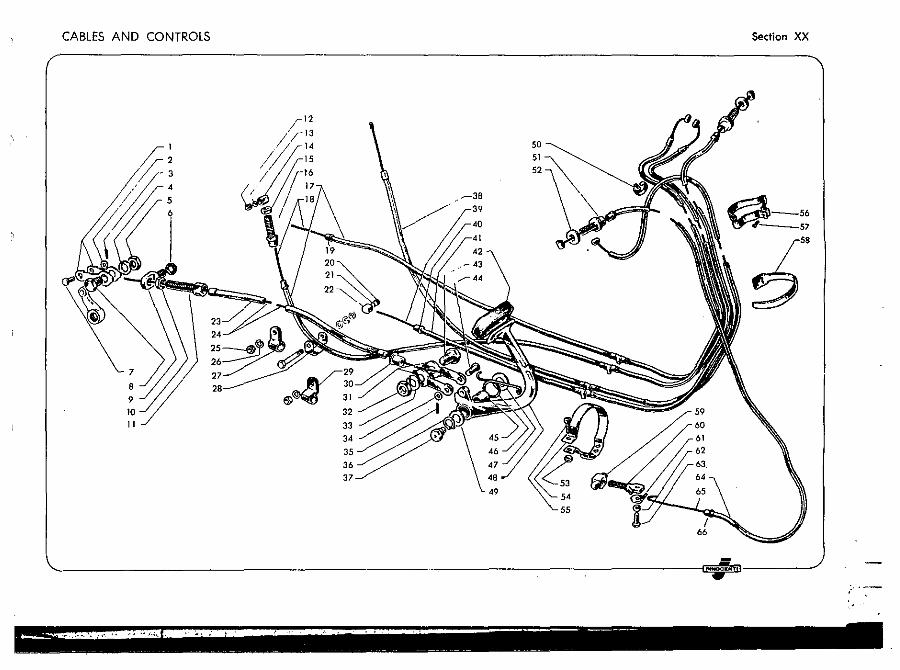
CABLES AND CONTROLS Section XX
." ....-38
~-5. -57
~ 9 10 32
" 33 34
35 3. 37
49
-'-' --~ -
~- - - ~ -
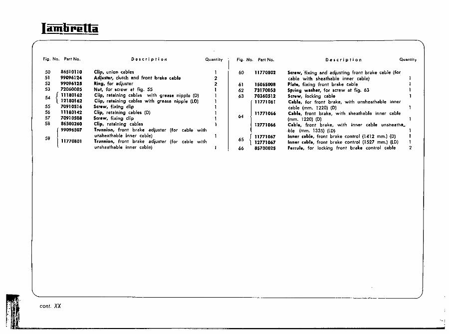
Iamlirl!Ua
Fig. No. ParI No.
50 86510110 51 99096124
99096125 72060005
54 f 11180162 l 12180162
70910516 11180142 70910508 86500260
52 53
55 56 57 58
59
f 99096507
111770801
Doscription Quantity
Clip, union c<lIbles Adjust.r, clutch and front brake cable Ring, for adjuster Nut, for ,crew at fig. 55 Clip, retaining cables with grease nipple (0) Clip, retaining cables with grease nipple (LD) Screw, fixing clip Clip, 'retaining c"bles (D) Screw, fixing clip Clip, retaining cables Trunnion, front brake adjuster (for cable with unsheathable inner cable) Trunnion, front brake adjuster (for cable with unshealhable inner cable)
1 2 2 1
Fig. No. ParI No.
60
61 62 63
64
65
66
11770802
15065008 73170053 70360512 11771061
11771066
12771066
I 11771067 l 12771067
85700025
Description QUilintiTy
Screw, 'fixing and adjusting front brake cable (for cable with sheathable inner cable) PI')'e, fixing front brake cable Spring wuh.r, for screw at fig. 63 Screw, locking cable C.ble, for front brake, with unsheathable inner cable (mm. 1220) (D) C.bl., front brake, with sheathable inner cable (mm. 1220) (0) C.bl., front brake, with inner cable unshoiltha_ ble (mm. 1335) (lO) Inner cabl., front brake control (1412 mm.) (D) Inner ubi., front brake control (1527 mm.) (lo) 1 Ferrule, for locking front brake control cable 2
~ '------------------------------------------________________________ J
f'u:... ___ c_o_n_t._x_x __________________ ~~_~~~ ______________________________ .. ,
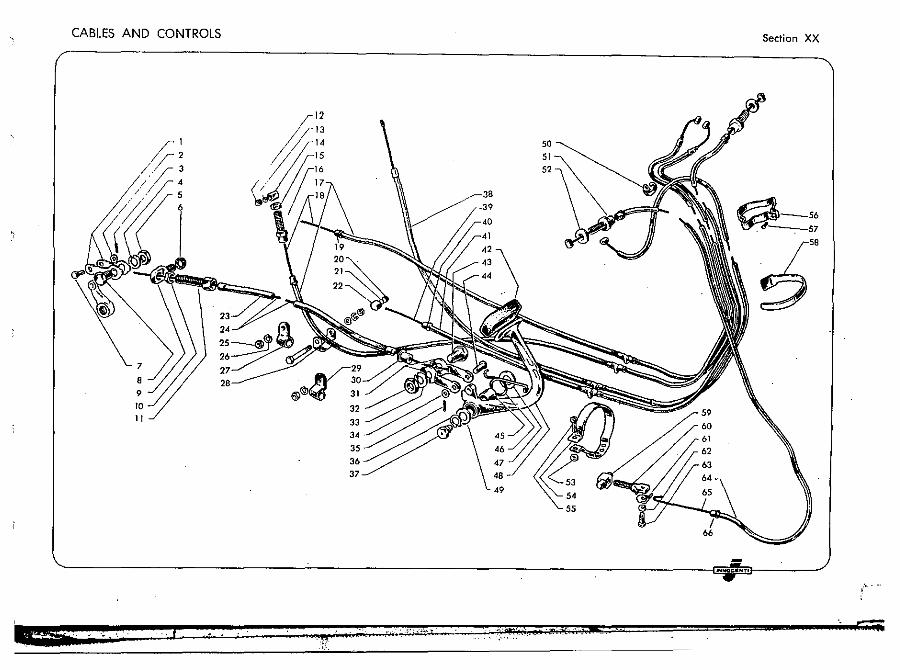
CABLES AN D CONTROLS
10
"
2
3
32 33
3' 35 36 37
Section XX
~-56 . ----:--57
.158
~
:~ .
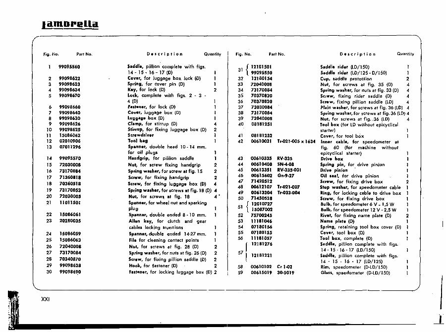
lilmDrellil
Fig. No. Part No.
99095560
2 3 4 5
6 7 8 9
10 11 12 13
14 15 16 17 18 19 20 21
22 23
24 25 26 27 28 29 30
XXI
99098622 99098623 99098634 99098670
99098660 99098640 99098630 99098626 99098625 15086062 02010906 07011296
99095570 72030008 73170014 71360818 70360518 73170053 72030005 11011501
15016061 20280035
15086059 15086063 72040008 73170084 70340870 99098628 990986~0
Description Quantity
Silddl., pillion complete with figs. 14 - 15 - 16 - 17 (D) Co .... r, fat luggage box lock (0) Spring, for cover pin (0) 1 K.y, for lock (D) 2 Lock, complete with figs. 2 - 3 " 4 (D) Fast.n.r, for lock (D) Cov.r, luggage box (D) 1 Luggag. box (D) I Cramp, for stirrup (D) '" Stirrup, for fixing luggage box (D) 2 Screwdriver 1 Tool bilg 1 Spann.r, double head 10 -14 mm. for oil plugs Handgrip, for pillion saddle Nut, for screw fixing handgrip 2 Spring washar, hr screw at fig. 15 2 Screw, for fixing handgrip 2 Screw, for fixing luggage box (0) 4 Spring wilsher, for screws at fig. 18 (~) 4 Nut, for screw~ at fig. 18 4 • Spanner, for wheel nut and sparking plug Spilnn.r, double ended 8 - 10 mm. Allen key, for clutch and gear cables locking trunnions Spanner, double ended 14-27 mm. File for cleaning contact points Nut, for screws at fig. 28 (D) 2 Spring washer, for nuts at fig. 26 (0) 2 Screw, for fixing pillion saddle (D) 2 Hook, for fastener (D) 2 FlISt.n.r, for locking luggage box (D) 2
Fig. No. Part No.
31 { 12181501 99095550
32 12180154 33 72040008 34 73170084 35 70370820 36 70370820 37 73030084 38 73170084 39 72040008 40 08181251
41 08181252 42 00610021 Tr-021.()()5 x 1634
43 00610335 RV-335 44 00610408 SN-4-08 45 00613351 RV-33,-oOI 46 00615602 Gn·9.27 47 71420512 48 00612107 Tr-021-o07 49 00613304 T...o33-o04 50 71450528
1 { 12010727 5 15087002 52 75700245 53 III 11 0<6 54 07180156 55 07180155 56 11181057
f 12181276
57! 12181221
58 00610102 Cr 1-02 59 00615019 3~5019
Description Quantity
Saddle rider (lD/150) 1 Silddl. rid.r (LD/125· 0/150) 1 Cup, saddle protection 2 Nut, for screws at fig. 35 (D) -4 Spring washer, for nuts al fig. 33 (D) 4 Screw, fixing rider saddle (D) -4 Sc,..w, fixing pillion saddle (to) -4 PI .. ;n wash.r, for screws at fig. 36 (lO) 4 Spring wilsh." for screws at fig. 36 (LO) 4 Nut, for screws at fjg .. 36 (LD) -4 Tool box (for to Without epicyclica! starler) Cover, for tool box Inner ubi., for speedometer at fig. 60 (for machine without epicyclical starter) Drive box Spring pin, for drive pinion 1 Drive pinion . I Oil .... r, for drive pinion 1 SC,.w, for fixing drive box 2 Stop wiII.h.r, for speedometer cable 1 Ring, for locking cable to drive box 1 SetflW, for fixing drive box 1 Bulb, for speedometer 6 V ~ 1,5 W 1 Bulb, for speedometer 12 V" 2,5 W 1 Rivet, for fixing name plate (0) 2 Nam. pia •• (0) 1 Spring, retaining tool box cover (0) 1 Cov.r, tool box (0) Tool box, complete (0) Saddl., pillion complete with figs. 14 - 15 -16 -17 (lD/150) Saddl., pillion complete with figs. 14 " 15 " 16 - 17 (LD/125) Rim, speedometer (0.LD/150) GlilSS, speedometer (D·lD/150)
!
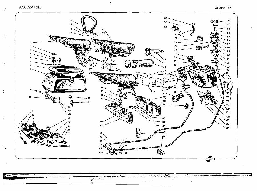
ACCESSORIES
5
6
7
•
9
10 __ , ...... ~
la -=--t=:=._. =-:-=,., ... , ... " .. :===:=",.' ~ .. -.-.. =::=
51
52~ 53~" fl \-" ----! 70~ ~
71 " 72 .. i} 73~ 74- -~P
Section XXI
~_.I
~ .2 • ,--83 :----'-'84
105
'NNOC"NT'
! .
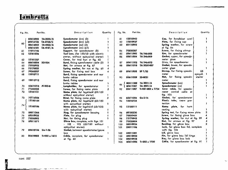
Iamlirella
Fig. No. Part No.
61 62
63 64 65 66 67 68
69
70 71 72
75 76 77 78
79
80
00613002 00613103 00614002 00614101 11011146 12181326
12181337 00610054 72000003 73170032 70360307 12010711
12010712
00611015 71203505 12181121
75710206 12180164
12180186
08011366 08010925 72000003 08011371
00610106
00610055
coni. XXI
TA·3002/A TA-3103/C T"'-4002/A TA·4101/A
50-054
PI DSS-8
Gn-1·06
Tr-055 x 1610
Description Quantity
Sp.edometer (km) (D) Sp .. dome.er (km) (lO) Sp •• domet.r (mi) (D) Spe.dome.er (mil (LD) Support, for speedometer (0) Tool box, (for ISO/lO with electric starter, without epicyclical starter) Cover, for tool box at fig. 62 Biilnd, fixing speedometer cable (D) Nut, for screws at fig. 67 Spring washer, for nut at fig. 65 Screw, for fixing 1001 box BoInd, fixing speedometer and rear brake cables Blind, fixing speedometer and rear brake cables
. Lampholder. for speedometer Screw, for fjxing name plate Nllma plet., for legshield (LO/150 without epicyclical starter) Rive., for fixing name plate N.lm. pl.l'., for legshield (lO/150 with epicyclical starler) N.lm. pl .. ,., for legshield (lO/125) with epicycJical starter) Plug, for speedometer housing PI.I'., for plug Nut, for fixing plug Gro .... box, complete, with fjgs. 101 - 102 - 103 (lD/150 without epityclical starter) Gasket, between speedometer/glo ... e box c.llbr., complete, for speedometer at fig. 60
1 1 1 4 4 4
1 1 2
1 2
Fig. No. Part No.
81 '2010940 82 12010937 83 83110003
84 70850307 85 00611002 TA 246-005 86 00611004 fA 246-009
87 00611003 fA 246-003 88 00611010 TA 3050-007
89 00611 008 5F 1/33
90 00611009 25·6021
f 00611000 91 \ 00611001 92 00611007
TA 3051/A TA 40SI/A Tr-021.()()5 x 1724
93 00611005 Gn-2·14 94 12010726
95 12180111
96 08180230 97 70850409 98 73170043 99 72030004
100 06010924 101 08011106
102 08011381 103 08010923 104 08010928 105 00611006 Tr-055 x 1700
Description Quantity
C .. p, for handlebar cowl PI.lI., for fixing cap Spring w.lsher, for screw at fig. 84 Screw, for fixing stirrup Rim, for speedometer G.lSket, upper, for speeqo. meter glass Glass, for speedometer G .. sket, lower, for speedometer glass Stilrup, for fixing speedo· LO meter epicycl. Nut, for fixing speedo- starter meter Speedomeler (km) Sp.edomet.r {mil Inner ubi., for speedometer control cable at fig. 105 G.lSket, for speedometer PlilStic lube, cable protection N.lm. plate, for horn casting Spring nut, for fixing name plate Screw. for fixing" glove box Spring w.lsher, for nut at fig. 99 Nut, for screws at fig. 97 Buding. for glove box Lock, for glove box lid, complete with fig. 104 lid, glove box Pin, for glove box lid hinge Key, for glove box lock C.lbl., for speedometer at fig" 91
1 2 4 4 4 2
1 1 2 1
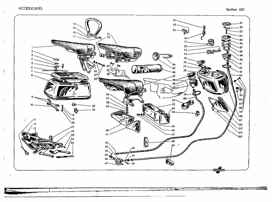
ACCESSORIES
6
7
8
9
10
11
"
t Q
,::~ 20
29 30
. .... , ...
Section XXI
~_81
~ 82 e 1--83
:::---..-. 84
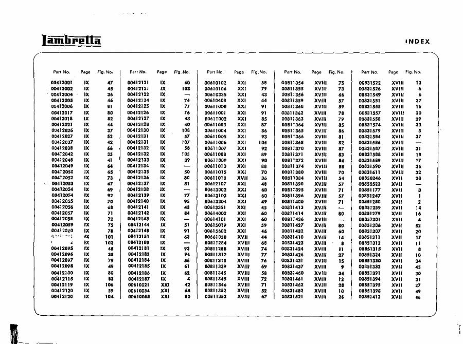
1--
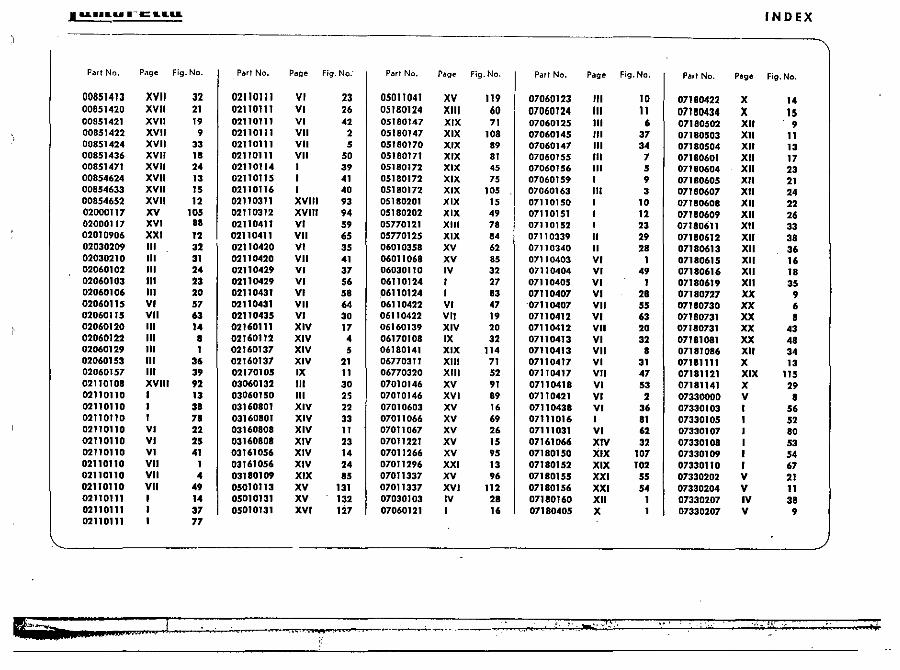
• .......... -tr:L ..... INDEX
IfhAr ) 4' ... II ..... ., i Ii
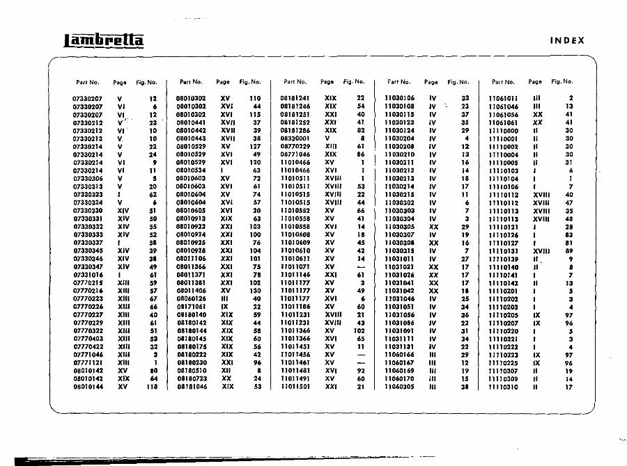
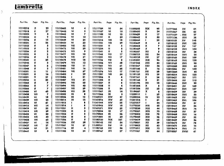
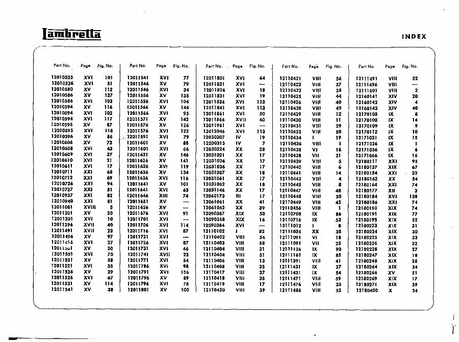
IandirelLa INDEX
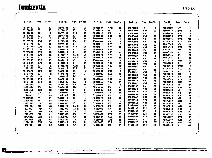
.'~. ========~========~==================~.="'~'==========~~~~ = ~ "'""".n..... ,j., . , •• , ~-'.. -_... .. ..
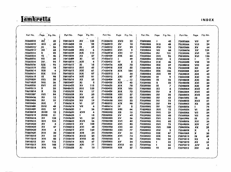
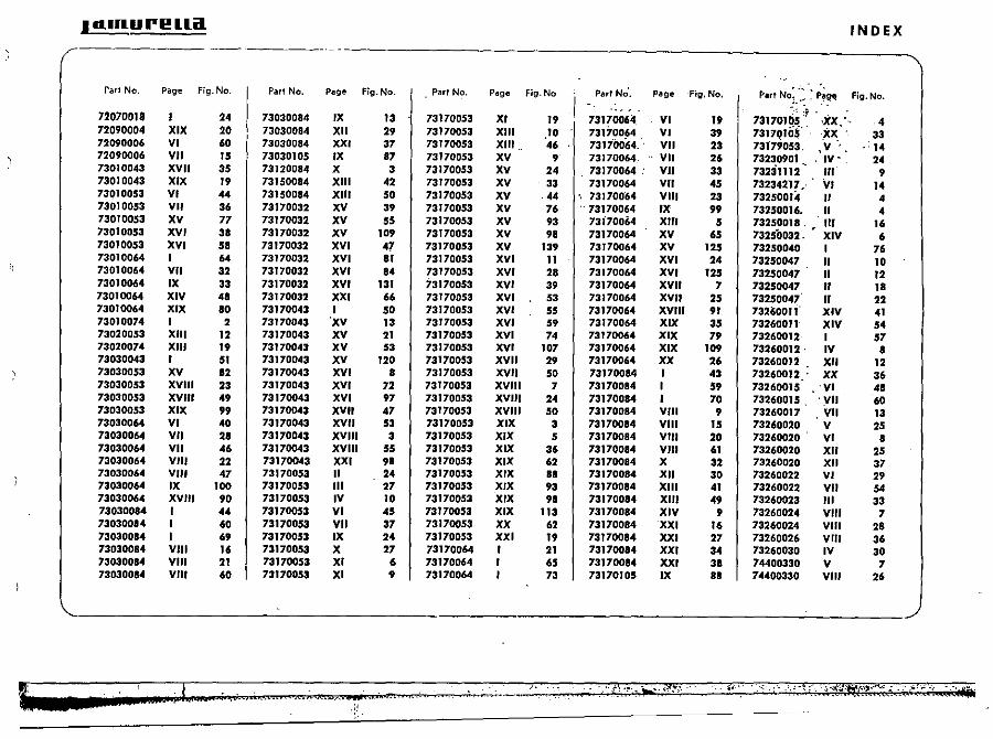
I dlnU (WI!! ua INDEX
rafl No. Page Fig.No. Part No. Page Fig.No. ParI No. Page Fig.No ParI No', Page Fig,No. Part No: .~ ~ p~~ Fig, No. ;.... .
72070018 of -,XX:' I 24 73030084 IX 13 731700S3 XI 19 73170064 VI 19 731701~~, ' 4
72090004 XIX 20 73030084 XII 29 73170053 XIII 10 73170064 VI 39 73170l0!: XX 33 12090006 VI 60 73030084 XXI 37 73170053 XIII .. 46 73170064. " VII 23 73f7;053, ,'V", 14 72090006 VII 15 73030105 IX 87 73170053 XV 9 73170064. VII 26 732~0901 .. . IV· . 24 73010043 XVII 35 73120084 X 3 73170053 XV 24 73170064' VII 33 73231112 III 9 73010043 XIX 19 73150084 XIII 42 73170053 XV 33 73170064 VII 45 73234217 .. VI 14 731;.10053 VI 44 73150084 XIII 50 73170053 XV ,44 731700"64 VIII 23 73250014 II 4 73010053 VII 36 73170032 XV 39 73170053 XV 76 . 73170064 IX 99 73250016. II 4 73010053 XV 77 73170032 XV 55 73170053 XV 93 73i70064 XIII 5 73250018. .. III 16 73010053 XVI 3a 73170032 XV 109 73170053 XV 98 73170064 XV 65 73250032. XIV 6 73010053 XVI 58 73170032 XVI 47 73170053 XV 139 73170064 XV 125 73250040 I 76 73010064 I 64 73170032 XVI 81 73170053 XVI II 73170064 XVI 24 73250047 II 10 73010064 VII 32 73170032 XVI 84 731700.53 XVI 28 73170064 XVI 12. 73250047 II 12 73010064 IX 33 73170032 XVI 131 731700.53 XVI 39 73170064 XVII 7 732.50047 II IB 73010064 XIV 4a 73170032 XXI 66 731700.53 XVI 53 73170064 XVII 25 73250047 II 22 73010064 XIX 80 73170043 I 50 73170053 XVI 55 73170064 XVIII 91 73nOOli XIV 41 73010074 I 2 73170043 'XV 13 731700.53 XVI 59 73170064 XIX 35 73260011 XIV 54 73020053 XIII 12 73170043 XV 21 731700.53 XVI 74 73170064 XIX 79 73260012 I 57 73020074 XIII 19 73170043 XV 53 73170053 XVI 107 73170064 XIX 109 73260012· IV 8 73030043 I 51 73170043 XV 120 731700.53 XVII 29 73170064 XX 26 73260012 XII 12 730300.53 XV 12 73170043 XVI 8 731700.53 XVII 50 7317008.4 I 43 73260012 .. XX 36 730300.53 XVIII 23 73170043 XVI 72 731700.53 XVIII 7 73170084 I 59 7326001.5 'VI 48 730300.53 XVIII 49 73170043 XVI 97 73170053 XVIII 24 73170084 I 70 73260015 . ')III 60 73030053 XIX 99 73170043 XVII 47 731700.53 XVIII 50 73170084 VIII 9 73260017 VII 13 73030064 VI 40 73170043 XVII 53 73170053 XIX 3 73170084 VIII 15 73260020 V 25 13030064 VII 2a 73170043 XVIII 3 731700.53 XIX 5 73170084 VIII 20 73260020 VI a 73030064 VII 46 73170043 XVIII 55 731700.53 XIX 36 73170084 VIII 61 73260020 XII 25 73030064 VIII 22 73170043 XXI 98 731700.53 XIX 62 73170084 X 32 73260020 XII 37 73030064 VIII 47 73170053 II 24 73170053 XIX 8a 73170084 XII 30 73260022 VI 29 73030064 IX 100 73170053 III 27 731700.53 XIX 93 73170084 XIII 41 73260022 VII 54 73030064 XVIII 90 73170053 IV 10 731700.53 XIX 98 73170084 XIII 49 73260023 III 33 73030084 I 44 73170053 VI 45 731700.53 XIX 113 73170084 XIV 9 73260024 VIII 7 73030084 I 60 73170053 VII 37 73170053 XX 62 73170084 XXI 16 73260024 VIII 28 73030084 I 69 731700.53 IX 24 73170053 xxi 19 73170084 XXI 27 73260026 VIII 36 73030084 VIII 16 731700.53 X 27 73170064 I 21 73170084 XXI 34 73260030 IV 30 73030084 VIII 21 731700.53 XI 6 73170064 I 65 73110084 XXI 3a 74400330 V 7 73030084 VIII 60 73170053 XI 9 73170064 I 73 73170105 IX 81 74400330 VIII 26
de , '
.,; "0. I i;.... ".If KC,"'"? ..... ,.;iR" •.. '.,-
"::'"
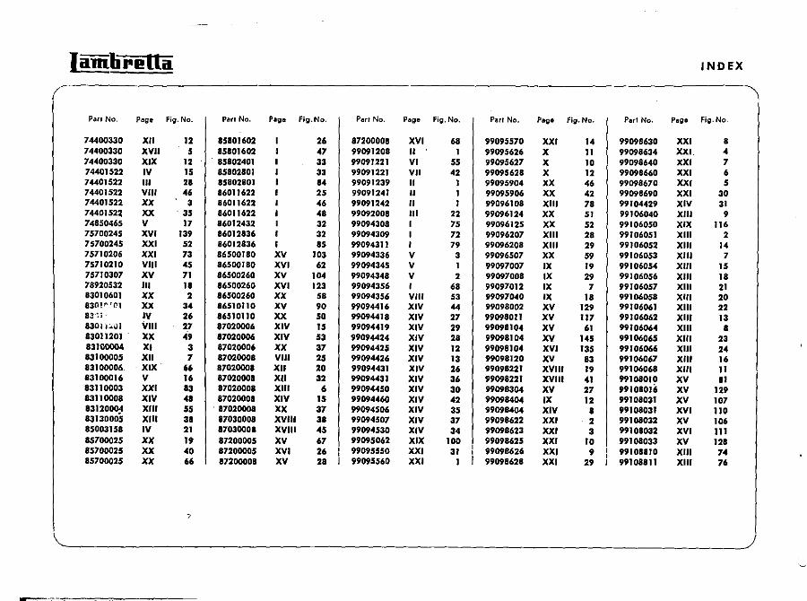
Iamli"I!Ua INDEX
(- \ PM. No. Page Fig. No. Part No. Page Fig.No. Pari No. Page Fig.No. ParI No. Page Fig.No. Part No. Page Fig.No.
74400330 XII 12 85801602 26 87200008 XVI 68 99095570 XXI 14 99098630 XXI 8 74400330 XVII 5 85801602 47 99091208 II I 99095626 X 11 99098634 XXI. 4 74400330 XIX 12 . 85802401 33 99091221 VI 55 99095627 X 10 99098640 XXI 7 74401522 IV 15 85802801 33 99091221 VII 42 99095628 X 12 99098660 XXI 6 74401522 III 28 85802801 84 99091239 " I 99095904 XX 46 99098670 XXI 5 74401522 VIII 46 86011622 25 99091241 " I 99095906 XX 42 99098690 XXI 30 74401522 XX 3 86011622 46 99091242 " I 99096108 XIII 78 99104429 XIV 31 7440152~ XX . 35 86011622 48 99092008 III 22 99096124 XX 51 99106040 XIII 9 74850465 V 17 86012432 I 32 99094308 I 75 99096125 XX 52 99106050 XIX "" 75700245 XVI 139 86012836 I 32 99094309 I 72 99096207 XIII 28 99106051 XIII 2 75700245 XXI 52 86012836 I 85 99094311 I 7. 99096208 XIII 2. 99106052 XIII 14 75710206 XXI 73 86500180 XV 103 99094336 V 3 99096507 XX 59 99106053 XIII 7 75710210 VIII 45 86500180 XVI 62 99094345 V I 99097007 IX 19 99106054 XIII IS 75710307 XV 71 86500260 XV 104 99094348 V 2 99097008 IX 29 99106056 XIII 18 78920532 III II 86500260 XVI 123 99094356 I 68 99097012 IX 7 99106057 XIII 21 83010601 XX 2 86500260 XX 58 99094356 VIII 53 99097040 IX 18 99106058 XIII 20 83(1P"C'1 XX 34 86510110 XV 90 99094416 XIV 44 99098002 XV 129 99106061 XIII 22 83·~j - IV 26 86510110 XX 50 99094418 XIV 27 99098011 XV 117 99106062 XIII 13 8301,':"0) VIII 27 87020006 XIV 15 99094419 XIV 29 99098104 XV 61 99106064 XIII 8 83011201 lq( 49 87020006 XIV 53 99094424 XIV 28 99098104 XV 145 99106065 XIII 23 831_ XI 3 87020006 XX 37 99094425 XIV 12 99098104 XVI 135 99106066 XIII 24 83100005 XII 7 87020008 VIII 25 99094426 XIV 13 99098120 XV 83 99106067 XIII J6 83100006. XIX 66 87020001 XII 20 99094431 XIV 2. 99098221 XVIII 19 99106068 XIII II 83100016 V I. 87020008 XU 32 99094431 XIV 36 99098221 XVIII 41 99108010 XV II 83110003 XXI 83 87020008 XIII 6 99094450 XIV 30 99098304 XV 27 99108016 XV 129 83110008 XIV 41 87020008 XIV 15 99094460 XIV 42 99098404 IX 12 99108031 XV 107 83120~ XIII 55 87020001 XX 37 99094506 XIV 35 99098404 XIV 8 99108031 XVI 110 83130005 XIII 31 87030008 XVIII 38 99094507 XIV 37 99098622 XXI 2 99108032 XV 106 85003158 IV 21 87030008 XVIII 45 99094530 XIV 34 99098623 XXI 3 99108032 XVI 111 85700025 XX 19 87200005 XV 67 99095062 XIX 100 99098625 XXI 10 99108033 XV 128 85700025 XX 40 87200005 XVI 2. 99095550 XXI 31 99098626 XXI 9 99108810 XIII 74 85700025 XX 66 87200008 XV 28 99095560 XXI I 99098628 XXI 29 99108811 XIII 76
7
\_-----------------------------------------------------------~)
.,.==;" -
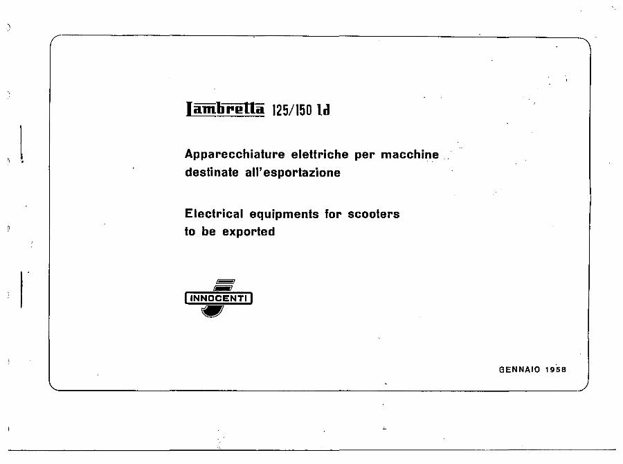
Iamlirl!lla 125/150 ld
Apparecchiature elettriche per macchine
destinate all' esportazione
Electrical equipments for scooters
to be exported
I I -I INNOCENTI I .. GENNAIO 1958
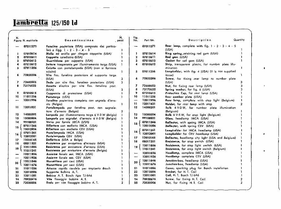
Iamlirella 125/150 Id
N. figurll N. matricol.
2 3
• 5
6
7 8
9 10
11
12 13
" 15 {
16 {
17 18
19 {
20 {
21 22 23
2' 25
07011271
07010614 07010611 07010613 07010612 07011356
70850306
72660003 73170032
07010615 11 011256 12011996
1201)831
14080301 15080004 99108031 07011366 12012006 07011361 12012001 12010165 08011351 12011886 11011241 12011856 12011926 12011846 12011676 11011056 12010586 12011081 70850616 72030006
Denominazione N.
_ peui
Fanalino posferiore (USA) camposte dai partieelari a Ugg. 1 ·2 - 3 ··"4·5' Molli! ad anello per rit~gno cappetta (USA)" Coppett .. ca.adiolro -(USA) Gl,larnizione per co'pp~tta (USA) Settora trasparente. per iiJuminamenfo ,arga (USA) Calotla con portalampada (USA) (non si fornisce sdolto) Vite fiss. fanalino posteriore al suppette targa (USA) Dildo per 'lite fiss. fanalino posteriore (USA) Rosett.;! elastica per vile fiss. fanalino post. (USA) C .. ppuccio di protezione (USA) Portilla'Sii (US4) Fanillino posleriore completo con segnale d'arresto (Belgio) Porlalampada pcr fanalino post. con segnala. tore d'arresto (Belgio) Lampada per illuminamento targa 6 V-3 W (Belgio) Lampada per segnalat. d'arresto 6 V-S W (Belgio) Velro per fan ale IMCA (USA) Rifletlore can molletta IMCA (USA) Riflettore can molletta CEV (USA) Portarampada lMCA (USA) Porlalampada CEV (USA) DefreUore (USA e Belgo) Ruistenn per avvisatore d'arresto (USA) Resistenn per avvisatore d'arresto (USA) Resistenn per avvisatore d'arresto (Belgio) Anieme fanalc ant. IMCA (USA) Assieme fanale anI. CEV (USA) Morselliera per cavi (USA) Morsettiera per cav'l (USA) Attacco rapido candela per impianto Bosch Supporto boblna A. T. Bobina A. T. Bosch tipo TJ 6A6 Vite fissaggio bobina A. T. Dado per vite fissaggio bobina A. T.
3 3
3
2 1
1
1 1 2 2
Fig. No. Put No.
07011271
1 07010614 2 07010611 3 07010613 4 07010612
5 07011356
6 70850306
7 72660003 8 73170032 9 07010615
10 11011256 12011996
11 12011831 12 14080301
13 15080004 14 99108031
15 { 07011366 12012006
16 { 07011361 12012001
17 18
19 {
20 {
21 22 23
•• 25
12010165 08011351 12011886 11011241 12011856 12011926 12011846 12011676 11011056 12010586 12011081 70850616 72030006
Description Quantity
Rear lamp; complete with fig. . 2 - 3 . 4 . 5 (USA)
Ring spring, retaining red gem (USA) Red gem (USA)" ~.skel for red gem (USA) Strip, transparent plastic, for number plate illumination Lampholder, with fig. 4 (USA) (it is not supplied loc·se) Screw, for fixing rear lamp to number plate (USA) Nut, for fixing rear lamp (USA) Spring washer, for fig. 6 (USA) Protection Cap, for rear lamp (USA) Rear number plate (USA) Rear lamp, complete with stop light (Belgium) Holder, for rear lamp with stop Bulb 6 V-3 W, for number plate illumination (Belgium) Bulb 6 V-S W, for stop light (Belgium) GlilSS, head lamp IMCA (USA) Reflector, with spring fMCA (USA) Reflector, with spring CEV (USA)
lampholder for IMCA head lamp (USA) Lampholder for CEV head lamp (USA) Deflector, headlamp city light (USA and Belgium) Resistance, for stop switch (USA) Resistance, for stop light switch (USA) Resistance, for stop light switch (Belgium) Headlamp, complete IMCA (USA) Headlamp. complete CEV (USA)
Junction-box, head lamp (USA) Junction-box, head lamp (USA)
Cover, sparking plug for Bosch installation Bracket, for H. T. Coil Coil, H. T. Bosch TJ 6A6 Screw, for fixing H. T. Coil Nut, for fixing H. T. Coil
3 3 3
2
1 1 1 2 2
•
I
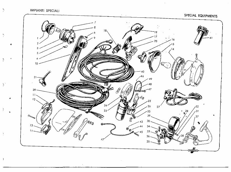
•
, .
•
•
IMPIANTI SPECIAL!
10
21J . . ~ 39 ----~.i,
SPECIAL EQUIPMENTS
~ -IH"OCIEr'TI
•
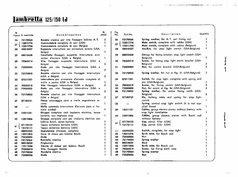
Iamlirl!Ua 125/150 ld
N. Figura N. matricola
29
30
31
32
73170064 12011776 12011756 08010427
08010428
70360414
72000004
73170043
33 07011281
34 70850518 35 72030005
36 73170053
37 07180731
38
39
40
42 43 44 45 4. 47 48 49
12011781
12011006
07170122 12170111 08090332 1201lSS6 72030006 73170064 08010534 12011046 70360614 73T700M 72030006
Dcnominazione
Roselta elastica per vile fiS5aggio bobina A. T. Commutator. completo di cavi (USA) Commutator. completo di cavi (Belgic) Supporto interruttore per avvisatore arresto (USA. lJelgio) Cavallotto fissaggio supporto interruffore avvisafore d'arreslo (USA e Belgic) Vita fissaggio $upporto interrutlore (USA e Belgic) Dado per vite fissaggio inferruttore (USA e Belgic) Rosetta elastica per vile fissaggio interrutt9re (USA e Belgio) Interruttore per avvisatore d'arresto completo di molla e perno (USA e Belgio)
N. peni
2 I
2
2
2
Vite fissaggio inlerruttore (USA e Belgio) 2 Dado per vile fissaggio interruttore (USA e ~~ 2 Rosen.. elastica per vite fissaggio interruffore (USA e Belgio) 2 Perno ancoraggio cavo e molla segnalatore ar-resto Moll .. comando interruttore d'arresto (non si fornisce sdoha) Gruppo completo cavi impianto eleffrico, senza batteria, con impianto stop Gruppo completo cav; per impianto eletfdco can bobina Bosch, senza batteria Tappo serbatoio benzin a (USA) T appo serbatoio benzina (USA) Se9n .. I .. ,ore d'arresto completo eno di massa per bobina Bosch Dado Ronden .. elaslica Prigioniero Trecel. di massa per bobina Bosch Vile fissaggio treccia Rondell. elastica D .. do
Fig_ No. P.ut No.
26 73170064
27 { 12011776 12011756
28 08010427
29 08010428
30 70360414
31 72000004
32 73170043
33 07011281
34 70850518 35 72030005 36 73170053
37 07180731
38
39 12011781
40 12011006
41 { 07170122 12170111
08090332 42 12011596 43 72030006 44 73170064 45 08010534 46 120]]046 47 70360614 48 73170064 49 72030006
Description Quantity
Spring wuher, for H_ T_ coil fixing nut Main switch, complete with cables (USA) Main switch, complete with cables (Belgium) 8rukel, for stop light switch (USA-Belgium)
Stirrup for fixing bracket, stop light switch (USABelgium) Screw, for fixing stop light swith bracket (USABelgium) Nut, for switch bracket (USA-Belgium)
Spring washer, for nut at fig. 31 (USA-Belgium)
Switch, for slop light, complete with spring and
2 1
2 2
2
pin (USA-Belgium) 1 Screw, for fixing switch (USA-Belgium) 2 Nul, for screw at fig. 34 (USA-Belgium) 2 Spring wilsher, for screw fixing ,with (USA-~~~ 2 Pin, locking cable and spring for stop light switch Spring, control stop light switch (it is not supplied loose) C.bln, group electric starter without battery with stop light installation C.blas, group electric starter with Bosch coil without battery C.p, petrol filler (USA) Cap, pelrol filler (USA)
Switch, complete, for stop light Euth wire, for Bosch coil Nut Spring wuher Stud E.rth wire, for Bosch coil Screw, for fixing earth wire Spring wiilSher Nut
1 1
l t
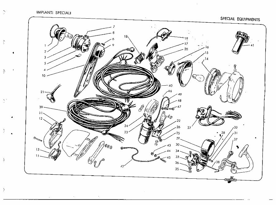
IMPIANTI SPECIALI
SPECIAL EQUIPMENTS
•
10
,. 2J~/ .~
•
•
:::: ' .... OCItNTl