Embed Size (px)
Citation preview

Lutron Electronics Co., Inc.7200 Suter RoadCoopersburg, PA 18036-1299, U.S.A.Made and printed in U.S.A. 9/09 P/N 030-1110 Rev. A
P/N
030-1110
P/N
030
-111
0P
/N 0
30-1
110
P/N
030-1110
120 V Halogen / Incandescent Dual DimmerS2-L, S2W-LRated at 120 V 60 Hz 600 W (300 W per circuit)
Important NotesPlease read before installing.1. CAUTION: To avoid overheating and possible damage to other equipment, do not use to control
receptacles, fluorescent lighting fixtures, motor-operated or transformer-supplied appliances.2. Dimmer requires separate wires in the wallbox for each light circuit.3. When no "grounding means" exist within the wall box the NEC© 2008, Article, 404.9 allows a
dimmer without a grounding connections to be installed as a replacement as long as a plastic, noncombustible wallplate is used. For this type of installation, cap or remove the green ground wire on the dimmer and use an appropriate wallplate such as the Lutron's Claro® series wallplates.
4. Do not use for lights switched from two locations (3-Way).5. Use only with permanently installed 120 V~ halogen or incandescent fixtures.6. Dimmer may feel warm to the touch during normal operation.7. For new installations, wire a test switch before installing the control.8. Install in accordance with all national and local electrical codes.9. Clean dimmer with a soft damp cloth only. Do not use any chemical cleaners.
Multi-Unit InstallationsWhen combining controls in a wallbox, remove all inner side sections before wiring (see below). Use pliers to bend each side section up and down until it breaks off. Repeat for each side section to be removed. Reduction of dimmer capacity is also required. Refer to chart below for maximum capacity.
Remove all inner side sections (shaded).
Do not remove outer side sections.
Model No Sides 1 Side 2 SidesNumber Load Removed Removed Removed S2-L Halogen / Incandescent 300 W / 300 W 250 W / 250 W 200 W / 200 W
Technical AssistanceIf you have questions concerning the installation or operation of this product, call the Lutron Technical Support Center. Please provide exact model number when calling. 1.800.523.9466 (U.S.A., Canada, and the Caribbean), for México, call +1.888.235.2910Other countries call +1.610.282.3800 Fax +1.610.282.6311 Internet: www.lutron.com
Limited Warranty (Valid only in the U.S.A., Canada, Puerto Rico, the Caribbean.)Lutron will, at its option, repair or replace any unit that is defective in materials or manufacture within one year after purchase. For warranty service, return unit to place of purchase or mail to Lutron at 7200 Suter Rd., Coopersburg, PA 18036-1299, postage pre-paid.THIS WARRANTy IS IN LIeU Of ALL OTHeR exPReSS WARRANTIeS, AND THe IMPLIeD WARRANTy Of MeRCHANTAbILITy IS LIMITeD TO ONe yeAR fROM PURCHASe. THIS WARRANTy DOeS NOT COVeR THe COST Of INSTALLATION, ReMOVAL OR ReINSTALLATION, OR DAMAge ReSULTINg fROM MISUSe, AbUSe, OR DAMAge fROM IMPROPeR WIRINg OR INSTALLATION. THIS WARRANTy DOeS NOT COVeR INCIDeNTAL OR CONSeqUeNTIAL DAMAgeS. LUTRON’S LIAbILITy ON ANy CLAIM fOR DAMAgeS ARISINg OUT Of OR IN CONNeCTION WITH THe MANUfACTURe, SALe, INSTALLATION, DeLIVeRy, OR USe Of THe UNIT SHALL NeVeR exCeeD THe PURCHASe PRICe Of THe UNIT. This warranty gives you specific legal rights, and you may have other rights which vary from state to state. Some states do not allow the exclusion or limitation of incidental or consequential damages, or limitation on how long an implied warranty may last, so the above limitations may not apply to you. Lutron, Claro and Skylark are registered trademarks of Lutron Electronics Co., Inc. NEC is a registered trademark of the National Fire Protection Association, Quincy, Massachusetts. © 2009 Lutron Electronics Co., Inc.
ground
black
Red
yellow
Wire the control: •Connectthegreengroundwireonthe
dimmer to the green or bare copper ground wire in the wallbox. If there is no ground wire in your wallbox, consult an electrician. (See important note 3.)
•Connecttheblackwireonthedimmerto the tagged wallbox wire removed from the switch (feed wire from breaker panel).
•Connecttheredwireonthedimmertothe wallbox wire leading to one of the lights.
•Connecttheyellowwireonthedimmer to the wallbox wire leading to the other light.
Mount and align dimmer. Install wallplate.
Turn power ON.
Operation
InstallationFor installations involving more than one control in a wallbox, refer to Multi-Unit Installations before beginning.Separate wires are required in the wallbox for each light circuit.
Turn power Off at circuit breaker or remove fuse.
for new construction go to Step 5.
Remove wallplate. Pull switch from wall.
Verify application. This dimmer mounts in a single-gang wallbox and controls two independent lights, 300 W maximum for each slider. Independent wire must be provided for each light.
Disconnect switch wires.
Prepare wires. Twist and trim wires to the proper length indicated below when completing Step 6.
3/8 in(10 mm)
Strip length: 3/8 in (10 mm) for 14–18 AWG (1.5–0.75 mm2).
Note: Wire connectors provided are suitable for copper wire only. For aluminum wire, consult an electrician. Use to join the following combinations:One 14 AWG (1.5 mm2) wire with one 16 or 18 AWG (1.5 or 0.75 mm2) wire.
green
bright
Dim
Off
LIgHT
bright
Dim
Off
LIgHT
Turn screws to loosen.
break-off fin
Tag
Tag
Tag the wire that is connected to the feed side of the switch (the side with the break-off fin).
Twist wire connector tight.
be sure no bare wire is exposed.
ON
OFF
ON
OFF
ON
OFF
Align control and tighten screws.
Start screws.
Live black
ground
Red
yellow
Light
Light
Neutral
green
ON
OFF
ON
OFF
ON
OFF
Lutron Technical Support Center 1.800.523.9466 24 hrs / 7 days www.lutron.com
1
2
3
4
5
6
7
8
120 V60 Hz
~120 V~60 Hz
WARNINg: Shock Hazard. May result in serious injury or death. Turn off power at circuit breaker before installing the unit.
Número Sin eliminar Una Sección Dos Seccionesde Modelo Carga Secciones eliminada eliminadas
S2-L Halogeno / Incandescente 300 W / 300 W 250 W / 250 W 200 W / 200 W
Lutron Electronics Co., Inc.7200 Suter RoadCoopersburg, PA 18036-1299, U.S.A.Fabricado e impreso en E.U.A. 9/09 P/N 030-1110 Rev. A
Atenuador Halogeno 120 V Incandescente de Control DualS2-L, S2W-LClasificado a 120 V 60 Hz de 600 W (300 W por circuito)
Notas Importantesfavor de leer antes de instalar. 1. Precaución: Para evitar un recalentamiento o daño a otros equipos, no instale para controlar receptáculos, accesorios fluorescentes, equipos motorizados, o equipos subministrados por transformadores. 2. Se necesitan alambres dedicados para cada circuito del atenuador. 3. Si en la caja de embutir no hay acceso a una conexión de tierra, la norma NEC® 2008, Artículo 404.9 permite instalar como reemplazo un atenuador sin conexión a tierra, en tanto se utilice una placa de pared de plástico no
combustible. Para este tipo de instalación, aísle o elimine el conductor verde de tierra del atenuador y utilice una placa de pared adecuada tal como la ClaroTM de Lutron
4. No use para luces controladas desde dos interruptores (3-vías). 5. Use solamente en instalaciones permanentes de 120 V~ de halógeno o incandescente. 6. El atenuador puede sentirse tibio al tacto durante su operación normal. 7. Para instalaciones nuevas cablee un interruptor de prueba antes de instalar el control. 8. La instalación se debe realizar de acuerdo con todas las reglamentaciones de los códigos eléctricos nacionales y locales. 9. Limpie la unidad con un paño suave y húmedo únicamente. No use agentes químicos de limpieza.
Instalaciones de Unidades MultiplesCuando combine controles en la caja de embutir, elimine todas las secciones laterales internas antes de conectar los alambres (vea el diagrama siguiente). Para eliminar las secciones laterales internas, use un alicate para doblarlas cuidadosamente hasta que se separen. Repita este proceso para cada sección que necesite eliminar. Reducción de la capacidad del control se requiere en este caso. Use la tabla siguiente para determinar la capacidad nueva del control.
elimine todas las secciones laterales internas (sombreadas).
No elimine las secciones laterales éxternas.
Asistencia TécnicaSi tiene preguntas referente a la instalación o operación de este producto, llame a Centro de Soporte Técnico de Lutron. Por favor suministre el numero exacto del modelo con su llamada. 1.800.523.9466 (E.U.A., Canadá, y el Caribe), para México, llame +1.888.235.2910de otros países, llame +1.610.282.3800Fax +1.610.282.6311 Internet: www.lutron.com
garantía Limitada (Válido solamente en los e.U.A., Canadá, Puerto Rico, y el Caribe.)Lutron reparará o reemplazará, a su criterio, cualquier unidad cuyos materiales o fabricación resulten defectuosos en el término de un año después de la fecha de compra. Para obtener servicio de garantía, la unidad debe devolverse al lugar de compra o enviar, con franqueo pago, a Lutron, 7200 Suter Road, Coopersburg, Pennsylvania 18036-1299.eSTA gARANTÍA Se OfReCe eN LUgAR De CUALqUIeR OTRA gARANTÍA exPReSA. LA gARANTÍA IMPLÍCITA De COMeRCIAbILIDAD eSTÁ LIMITADA A UN AÑO, A PARTIR De LA feCHA De COMPRA. eSTA gARANTÍA NO CUbRe LOS COSTOS De INSTALACIÓN, DeSMONTAJe NI ReINSTALACIÓN. TAMPOCO CUbRe DAÑOS ReSULTANTeS De UN USO IMPROPIO O AbUSO, NI DAÑOS DebIDOS A UNA INSTALACIÓN O CONexIÓN INCORReCTA. eSTA gARANTÍA NO CUbRe DAÑOS INCIDeNTALeS NI ReSULTANTeS. LA ObLIgACIÓN De LUTRON CON ReSPeCTO A CUALqUIeR ReCLAMACIÓN POR DAÑOS ReLACIONADOS CON LA fAbRICACIÓN, VeNTA, INSTALACIÓN, eNTRegA, USO, RePARACIÓN O ReeMPLAZO De LA UNIDAD, NO SUPeRARÁ, eN NINgÚN CASO, eL PReCIO De COMPRA.Esta garantía otorga derechos legales específicos, pero se podría tener otros derechos, que varían de un estado a otro. Algunos estados no permiten la exclusión o limitación de daños incidentales ni resultantes, ni limitaciones en la duración de una garantía implícita, por lo cual es posible que las limitaciones mencionadas anteriormente no correspondan en ciertos casos.Lutron, Claro y Skylark son marcas registradas de Lutron Electronics Co., Inc. NEC es una marca registrada de National Fire Protection Association, Quincy, Massachusetts. © 2009 Lutron Electronics Co., Inc.
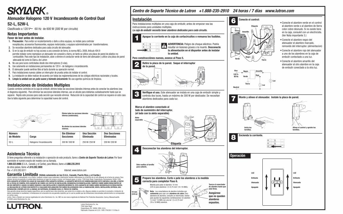
Conecte el control:•Conecteelalambreverdeenelcontrol
al alambre verde o al alambre de tierra color cobre desnudo. Si no existe tiera en la caja, consulet con un electricista. (Ver Nota importante 3.)
•Conecteelalambrenegrodelatenuador el alambre marcado, removido del interruptor. (alimentacion)
•Conecteelalambrerojodelatenuadora uno de los alambres en la caja de embutir contectado a una luz.
•Conecteelalambreamarillodelatenuador al otro alambre en la caja de embutir conectado a la otra luz.
Monte y alinee el atenuador. Instale la placa de pared.
encienda la corriente.
Operación
InstalaciónPara instalaciones múltiples en una caja de embutir, antes de empezar vea las instrucciones para unidades múltiples.La caja de embutir necesita tener alambres dedicados para cada circuito.
Apague la corriente en la caja de cortacircuitos o remueva los fusibles.
Para construcciónes nuevas, avance al Paso 5.
Retire la placa de la pared. Saque el interruptor de la pared.
Verifique el uso. Este atenuador se instala en una caja de embutir simple y controla dos luces, hasta un máximo de 300 W por deslizador. Se necesitan alambres dedicados para cada luz.
Desconectar los alambres del interruptor.
Prepare los alambres. Corte o pele los alambres a la medida correcta para completar Paso 6.
Dele vueltas al tornillo para soltarlo.
ON
OFF
ON
OFF
ON
OFF
Alinee el control y apriete los tornillos.
Inicie los tornillos.
Marca el alambre conectado al lado de suministro del interruptor. (el lado con la aleta separable)Aleta separable
etiqueta
10 mm(3/8 in)
Medida para pelar el alambre: 10 mm (3/8 in) para alambres 1,5–0,75 mm2 (14–18 AWG).
Nota: Los conectadores de alambre incluídos son solamente para usar con alambres de cobre. Para alambres de aluminio, consulte un electricista. Úselos para ajuntar las siguientes combinaciones: Un alambre 1,5 mm2 14 AWG con uno de 1,5 o 0,75 mm2 (16 o 18 AWG) alambre.
Tuerza el conectador de alambre hasta que este firme.
Asegúrese que no queden alambres expustos.
Tierra
Negro
Rojo
Amarillo
etiqueta
LUZ
brillante
Atenuada
Apagado
LUZ
brillante
Atenuada
Apagado
Verde
ON OFF
ON OFF
ON OFF
Neutral
120 V60 Hz
Negro
LuzTierra
Rojo
Amarillo
Luz
Vivo
Verde120 V~60 Hz
ON
OFF
ON
OFF
ON
OFF
Centro de Soporte Técnico de Lutron +1.888-235-2910 24 horas / 7 días www.lutron.com
1
2
3
4
5
6
7
8
ADVeRTeNCIA: Peligro de choque eléctrico. Podría resultar en lesiones graves o la muerte. Desconecte la alimentación en el disyuntor antes de instalar la unidad.
![Resilient Wind Turbine Design · 2019-04-03 · Frequency [Hz] f R . f R + 7 Hz f R - 7 Hz . 100 . Voltage [% of nominal] 80 85 . 120 . Normal continuous operation . max. 60s . 145](https://img.pdfslide.us/doc/110x75/5f08b3537e708231d4234c90/resilient-wind-turbine-design-2019-04-03-frequency-hz-f-r-f-r-7-hz-f-r-.jpg)