Embed Size (px)
Citation preview

US00925O352B2
(12) United States Patent (10) Patent No.: US 9.250,352 B2 Hardman (45) Date of Patent: Feb. 2, 2016
(54) METHODS FOR PRODUCING ALOG OF (56) References Cited MATERAL PROPERTIES
(76) Inventor: Richard H. Hardman, Houston, TX (US)
(*) Notice: Subject to any disclaimer, the term of this patent is extended or adjusted under 35 U.S.C. 154(b) by 642 days.
(21) Appl. No.: 12/937,311
(22) PCT Filed: Apr. 15, 2009
(86). PCT No.: S371 (c)(1), (2), (4) Date:
PCT/US2O09/040704
Oct. 11, 2010
(87) PCT Pub. No.: WO2009/137248 PCT Pub. Date: Nov. 12, 2009
(65) Prior Publication Data
US 2011 FOO292.45 A1 Feb. 3, 2011
Related U.S. Application Data (60) Provisional application No. 61/124.594, filed on Apr.
17, 2008, provisional application No. 61/054,881, filed on May 21, 2008, provisional application No. 61/206,584, filed on Feb. 2, 2009.
(51) Int. Cl. G06F 5/00 (2006.01) GOI/3/38 (2006.01) GOI/3/26 (2006.01)
(52) U.S. Cl. CPC. G0IV3/38 (2013.01); G0IV3/26 (2013.01)
(58) Field of Classification Search USPC .............................................................. 702/6 See application file for complete search history.
UPPER BED BUNDARY
HLE
U.S. PATENT DOCUMENTS
3,510,757 A 5, 1970 Huston 3,808.520 A 4/1974 Runge 4,980,643 A 12/1990 GianZero 5,115,198 A 5/1992 GianZero et al. 5,757,191 A 5/1998 GianZero 5,854,991 A 12/1998 Gupta 5.999,883. A 12/1999 Gupta et al. 6,092,024 A T/2000 Wu 6,147,496 A 11/2000 Stracket al. 6,304,086 B1 10/2001 Minerbo 6,556,016 B2 4/2003 Gao et al. 6,573,722 B2 6/2003 Rosthal 6,574,562 B2 6/2003 Tabarovsky et al. 6,727,705 B2 4/2004 Frey 6,760,666 B2 7/2004 Hagiwara 6,819,112 B2 11/2004 Gianzero et al.
2002/0173914 A1 2003. O146751 A1
11/2002 Zhang et al. 8, 2003 Rosthal
(Continued) OTHER PUBLICATIONS
Amundsen Lasse, PCT/EP05/052781, WO 2006/000538, Publica tion Date: Jan. 5, 2006, 53 pages.*
(Continued)
Primary Examiner — Tung S Lau
(57) ABSTRACT
A method for making a log of material properties in a plurality of beds from an instrument utilizes steps such as estimating material properties for said plurality of beds and/or estimat ing positions for a plurality of bed boundaries and/or estimat ing orientations for said plurality of bed boundaries wherein the bed boundary orientations are individually variable. The estimated positions, orientations, and/or material properties can be utilized to compute the log.
36 Claims, 13 Drawing Sheets
MIDDLE BED
OWER BED BUNDARY

US 9.250,352 B2 Page 2
(56) References Cited
U.S. PATENT DOCUMENTS
2003. O146753 A1 2003/O155924 A1 2003,0222651 A1 2004.0017197 A1 2005/O127917 A1 2005/0256642 A1 2006, OO385.71 A1 2006,0074561 A1 2006, O192562 A1 2007/0236221 A1 2007/0256832 A1 2008.OO78580 A1 2008.0143336 A1 2008, 0210420 A1 2008, 0215242 A1 2008/0221795 A1* 2008/0258733 A1 2008/0278169 A1 11, 2008 Bittar 2009, OO18775 A1 1/2009 Tabarovsky
OTHER PUBLICATIONS
8, 2003 Rosthal 8, 2003 Rosthal 12/2003 Tabanou 1/2004 Chen 6, 2005 Barber 11/2005 Barber 2/2006 Ostermeier 4/2006 Xia 8/2006 Davydychev 10/2007 Merchant 11/2007 Hagiwara 4/2008 Bittar 6/2008 Legendre 9/2008 Ramakrishnan 9/2008 Ramakrishnan 9/2008 Amundsen et al. ............... 702.5 10/2008 Bittar
P.G.Killeen, Surveying the Path of Boreholes: A Review of Orienta tion Methods and Experience, A Review of Orientation Methods and Experiences; in Proceedings of the 6th International MGLS Sympo sium on Borehole Geophysics for Minerals, Geotechnical and Groundwater Applications; Santa Fe, New Mexico, Oct. 22-25, 1995, 16 Pages.* B. R. Spies, Electrical and Electromagnetic Borehole Measurements: A Review, Surveys in Geophysics 17:517-556, 1996.(a) 1996 Kluwer Academic Publishers. Printed in the Netherlands. Hardman, et. al., Four Term Decomposition Techniques for a Faster Inversion of Induction Responses, Society of Petroleum Engineers, Inc., Oct. 5-8, 2003, SPE 84606, USA. Barber, et. al., Determining Formation Resistivity Anisotropy in the Presence of Invasion, Society of Petroleum Engineers, Inc., Sep. 26-29, 2004, SPE90526, USA. Wang, et. al., Triaxial Induction Logging: Theory, Modeling, Inver sion, and Interpretation, Society of Petroleum Engineers, Inc., Dec. 5-7, 2006, SPE 103897, China. Hardman, et. al., Theory of induction Sonde in dipping beds, Geophysics, Mar. 1986, p. 800-809, vol.51- No. 3, USA. PCT Preliminary Report.
J. Hou et al., “A New Multi-Frequency Triaxial Array Induction Tool for Enhancing Evaluation of Anisotropic Formations and Its Field Testing.” SPWLA 54th Annual Logging Symposium, Jun. 22-26, 2013, pp. 1-16. R. Rosthal et al., “Field Test Results of an Exponentially Fully Triaxial Induction Tool.” SPWLA 44th Annual Logging Symposium, Jun. 22-25, 2003, pp. 1-14. Z. Zhang et al., “Determination of relative angles and anisotropic resistivity using multicomponent induction logging data, Geophys ics, vol. 69, No. 4 (Jul.-Aug. 2004), pp. 898-908. Z. Zhang et al., “Simultaneous determination of relative angles and anisotropic resistivity using multicomponent induction logging data.” SPWLA 42nd Annual Logging Symposium, Jun. 17-20, 2001. T. Hagiwara, "Apparent dip and apparent anisotripy from multifrequency triaxial induction measurements.” Geophysics, vol. 76, No. 1, (Jan.-Feb. 2011), pp. F1-F13. T. Hagiwara, Determination of dip and anisotropy from transient triaxial induction measurements, Geophysics, vol. 77. No. 4 (Jul.- Aug. 2012), p. D105-d112. Zhanget al., “1-D Inversion of Triaxial Induction Logging in Layered Anisotropic Formation.” Progress in Electromagnetics Research B, V.44, pp. 383-403 (2012). Alpak et al., “Petraphysical Inversion of Borehole Array Induction Logs, Part I Numerical Examples.” Geophysics, V. 71, No. 4, p. F101-F119 (Jul.-Aug. 2006). Hardman et al., “Charts for Correcting Effects of Formation Dip and Hole Deviation on Induction Logs.” The Log Analyst, Jul.-Aug. 1987, pp. 349-354. Gianzero et al., “The Response of an Induction Dipmeter and Stan dard Induction Tools to Dipping Beds.” Geophysics, V. 55, No. 9, pp. 1128-1140 (Sep. 1990). Wang et al., “Determining Anisotropic Formation Resistivity at Any Relative Dip using a Multiarray Triaxial Induction Tool.” SPE 103 113 (Society of Petroleum Engineers, 2006). Weatherford, “Log Interpretation Charts Compact Tool Series.” 2007, www.weatherford.com. Hagiwara, “Directionality and Tri-axial Induction Log.” SPWLA 49th Annual Logging Symposium, May 25-28, 2008, pp. 1-8. Wang et al., “Fast and rigorous inversion of triaxial induction logging data to determine formation resistivity anisotropy, bed boundary position, relative dip and azimuth angles. Society of Exploration Geophysicists, document SEG-2003-0514, 2003 SEGAnnual Meet ing, Oct. 26-31, Dallas, Texas (2003).
* cited by examiner

US 9.250,352 B2 Sheet 1 of 13
CI38I IETICIÚII W
Feb. 2, 2016 U.S. Patent
] 'DI +

US 9.250,352 B2 Sheet 2 of 13 Feb. 2, 2016 U.S. Patent
E 'DI +
IETILIH

8 'DI +
US 9.250,352 B2
º In?ta SJÁ
Sheet 3 of 13 Feb. 2, 2016 U.S. Patent

US 9.250,352 B2 Sheet 4 of 13 Feb. 2, 2016
| | | | | |
£ LNID]d? | | | | | |
U.S. Patent

US 9.250,352 B2 U.S. Patent
9 'DI +

US 9.250,352 B2 Sheet 6 of 13 Feb. 2, 2016 U.S. Patent
/ 'DI + 3T}[]&ICI OI LENOVW Tº LNDIZINDH

US 9.250,352 B2 Sheet 8 of 13 Feb. 2, 2016 U.S. Patent


US 9.250,352 B2 Feb. 2, 2016 U.S. Patent

U.S. Patent Feb. 2, 2016 Sheet 12 of 13 US 9.250,352 B2
i

US 9.250,352 B2
ANVOIN?AT 18I (138||
U.S. Patent

US 9,250,352 B2 1.
METHODS FOR PRODUCING ALOG OF MATERAL PROPERTIES
This application claims benefit of and is a continuation application of PCT International Application No. PCT/ US2009/040704, filed Apr. 15, 2009, which claims benefit of U.S. Provisional Application 61/124,594, filed Apr. 17, 2008, U.S. Provisional Application No. 61/054,881, filed May 21, 2008, and U.S. Provisional Application No. 61/206,584, filed Feb. 2, 2009. PCT International Application No. PCT/ US2009/040704, filed Apr. 15, 2009, U.S. Provisional Appli cation 61/124,594, filed Apr. 17, 2008, U.S. Provisional Application No. 61/054,881, filed May 21, 2008, and U.S. Provisional Application No. 61/206,584, filed Feb. 2, 2009 are each incorporated herein by reference in their entirety.
BACKGROUND OF THE INVENTION
1. Field of the Invention The present invention relates generally to the field of log
ging of material properties and, in one possible specific embodiment, relates to methods and/or devices for making a log in layered environments. One possible non-limiting example includes producing a log of material properties with respect to borehole depth.
2. Description of the Background Subsurface geological formations typically comprise lay
ers of various types of formations. While the present inven tion is not limited to use in producing logs of a layered environment comprising Subsurface geological formations, an embodiment of the invention is conveniently described in terms of this environment.
Most oil and gas was originally deposited in an ocean environment. As a consequence. Such formations may contain fluids such as saltwater and/or oil. Salt water, with its mobile Sodium and chlorine ions makes the formation conductive to electricity, while the oil/gas makes the formation resistive. The oil companies typically utilize logging tools to produce a log of material properties of a wellbore. As one example, when the desired rock formation or depth is reached, the drill pipe and the bit are removed from the hole. An instrument is lowered into the wellbore to measure the electrical conduc tivity versus depth. In this way, a log or a record of the geologic formation is produced. Other instruments may gen erate a log of a wellbore while drilling. Generally, if the rocks are relatively conductive, they contain salt water. If the rocks are relatively resistive, they contain oil and/or gas. The earliest instruments used direct current and were first
used in 1927. In the 1950s, electromagnetic or induction tools were introduced. These electromagnetic instruments had coaxial coils, and measured just one component of the conductivity tensor of the rock. There are many different electromagnetic tools which measure various physical quan tities. The standard induction tools measure a Voltage while the measurement-while-drilling (MWD) tools measure phase differences and/or amplitude ratios. Other tools comprise many configurations such as laterolog tools, normal and lat eral tools, e-log tools and the like. The present invention may be utilized with these and other tools.
Oil is often deposited in a layered environment. There is an exact mathematical Solution to an electromagnetic instrument penetrating a parallel layered environment at any angle as per an article by the inventor. See, for example, Hardman and Shen, “Theory of Induction Sonde in Dipping Beds.” Geo physics Vol. 51, No. 3, March 1986, p. 800-809. However, in the real world, the interface between the layers is not neces sarily parallel.
5
10
15
25
30
35
40
45
50
55
60
65
2 Other background material may include Hardman and
Shen, “Charts for Correcting Effects of Formation Dip and Hole Deviation on Induction Logs.” The Log Analyst, Vol. 28, No. 4. p 349-356, July-August 1987; Hardman, “Four-Term Decomposition Techniques for a Faster Inversion of Induc tion Responses.” SPE84606, October 2003: Wang, Barber, et al., “Triaxial Induction Logging; Theory, Modeling, Inver sion, and Induction. SPE 103897, December 2006: Ander son, Barbara et al., “Effect of Dipping Beds on the Response of Induction Tools. SPE Formation Evaluation (March 1988), pp. 29-36; Barber, Anderson, et al., “Determining For mation Resistivity Anisotropy in the Presence of Invasion, SPE 90526, September 2004; Anderson, Barbara et al., “Response of 2-MHZ LWD Resistivity and Wireline Induc tion Tools in Dipping Beds and Laminated Formations', SPWLA31st Annual Logging Symposium, Jun. 24-27, 1990, Paper A, pp. 1-25; Barber, Thomas D. et al., “Interpretation of Multiarray Induction Logs in Invaded Formations at High Relative Dip Angles'. The Log Analyst, Vol. 40, No. 3 (May June 1999), pp. 202-21; Sommerfeld Partial Differential Equations in Physics, Academic Press 1949; U.S. Pat. No. 3,808,520; U.S. Pat. No. 6,304,086; U.S. Pat. No. 6,573,722: U.S. Pat. No. 6,216,089; U.S. Pat. No. 3,510,757; US 2006/ 0038571; US 2007/0256832; US 2003/0222651; US 2003/ 0146753; US 2003/0155924; US 2005/0127917; US 2004/ 0017197; US 2006/0192562; US 2003/0146751; US 2009/ 0018775; US 2008/0078580; US 2008/0210420; US 2008/ 0215241; US 2008/0258733; US 2008/0078580; US 2008/ 0278169; and US 2005/0256642.
Since around 2000, the tools have transmitter and receiver coils in the x, y and Z directions. These tri-axial instruments measure all the components of the conductivity tensor and are able to orient the individual bed boundaries. A change in bed boundary orientation may be indicative of a change in the depositional environment. Information concerning the orien tation of the bed boundary may be very useful in the geologic interpretation of the formation.
Consequently, there remains a long felt need for improved methods which may be utilized to produce more accurate logs in layered environments wherein the layers may or may not be parallel. Moreover, it sometimes desirable to more quickly calculate or invert logs. Because those skilled in the art have recognized and attempted to solve these problems in the past, they will appreciate the present invention, which addresses these and other problems.
SUMMARY OF THE INVENTION
An object of the invention is to provide an improved method of logging physical properties.
Another possible object of the present invention is to pro vide a faster method of computing and inverting a log.
Another possible object of the present invention is provide the ability to compute the log when any boundary has an individually variable orientation whereby the bed boundary effects are accurately accounted for in the log. (FIG. 1)
Another possible object of the invention is to provide improved accuracy of the positions and/or orientations of bed boundaries and/or the material properties of the beds.
Another possible object of the invention is to provide an improved method for geosteering a well.
Another possible object of a specific embodiment of the present invention is to determine a conductivity log from the composite magnetic field.
These and other objects, features, and advantages of the present invention will become apparent from the drawings, the descriptions given herein, and the appended claims. How
US 9,250,352 B2 3
ever, it will be understood that the above-listed objectives and/or advantages of the invention are intended only as an aid in understanding aspects of the invention, are not intended to limit the invention in any way, and therefore do not form a comprehensive or restrictive list of objectives, and/or fea tures, and/or advantages.
Accordingly, the present invention comprises a method for making a log of material properties in a plurality of beds from an instrument which produces an electromagnetic field. (See FIG. 11) In one embodiment, the invention may comprise steps such as, for example, estimating material properties for the plurality of beds and/or estimating positions for a plurality of bed boundaries and/or estimating orientations for the plu rality of bed boundaries wherein the bed boundary orienta tions are individually variable. Other steps may comprise utilizing the positions, and/or the orientations, and/or the material properties to compute the log. (See FIG. 1)
In one possible embodiment, an inversion process can be utilized to invert the log.
In one embodiment, the method may comprise varying the orientation for a selected one of a plurality of bed boundaries and utilizing the resulting orientations of the bed boundaries and/or the positions and/or the material properties of the beds to compute the log. The method may comprise varying a position for the selected bed boundary and utilizing the result ing positions of the bed boundaries and/or the orientations and/or the material properties to compute the log. The method may also comprise varying the material properties for a selected bed and utilizing the resulting material properties and/or positions and/or the orientations of the bed boundaries to compute the log.
In one embodiment, the method may comprise selecting a bed boundary from the plurality of bed boundaries, comput ing a transverse magnetic term one, and utilizing the trans verse magnetic term one to compute the log. (See FIG. 6) The method may also comprise computing a transverse magnetic term two and a transverse magnetic term three and/or a trans verse magnetic term four for the bed boundary and utilizing the transverse magnetic term one and/or the transverse mag netic term two and the transverse magnetic term three and/or the transverse magnetic term four to compute the log.
In one possible embodiment, the method may comprise selecting a bed from the plurality of beds wherein the bed has an upper bed boundary and a lower bed boundary (See FIG. 5), computing a first transverse magnetic term one for the upperbed boundary, computing a second transverse magnetic term one for the lower bed boundary, combining the first transverse magnetic term one and the second transverse mag netic term one to provide a combined transverse magnetic term one. (See FIG.9) Other steps may comprise utilizing the combined transverse magnetic term one to compute the log. The method may also comprise computing a transverse mag netic term two for the upper bed boundary, computing a transverse magnetic term three for the lower bed boundary, and utilizing the combined transverse magnetic term one, the transverse magnetic term two, and the transverse magnetic term three to compute the log. (See FIG. 8)
In another embodiment, the method may comprise select ing a bed boundary from the plurality of bed boundaries, computing a transverse electric term one, and utilizing the transverse electric term one to compute the log. The method may comprise computing a transverse electric term two and a transverse electric term three for the bed boundary and/or utilizing the transverse electric term one and/or the transverse electric term two and the transverse electric term three to compute the log.
10
15
25
30
35
40
45
50
55
60
65
4 In another embodiment, the method may comprise select
ing a bed from the plurality of beds wherein the bed has an upper bed boundary and a lower bed boundary, computing a first transverse electric term one for the upper bed boundary, computing a second transverse electric term one for the lower bed boundary, and combining the first transverse electric term one and the second transverse electric term one to provide a combined transverse electric term one. (See FIG. 9) The method may utilize the combined transverse electric term one to compute the log. The method may further comprise com puting a transverse electric term two for the upper bed bound ary, computing a transverse electric term three for the lower bed boundary, and utilizing the combined transverse electric term one, the transverse electric term two, and the transverse electric term three to compute the log. (See FIG. 8)
In yet another embodiment, the method may comprise selecting a bed boundary from the plurality of bed bound aries, computing a transverse electric up for the bed boundary and computing a transverse electric down for the bed bound ary. (See FIG. 10) The method may comprise utilizing the transverse electric up and the transverse electric down to compute the log. The method may also comprise computing a transverse magnetic term one and utilizing the transverse magnetic term one, the transverse electric up, and the trans verse electric down to compute the log. The method may comprise computing a transverse magnetic term one, a trans verse magnetic term two, and a transverse magnetic term three for the bed boundary, and utilizing the transverse mag netic term one, the transverse magnetic term two, the trans verse magnetic term three, the transverse electric up, and the transverse electric down to compute the log.
In another embodiment, the method of claim 1 may com prise selecting a bed from the plurality of beds wherein the bed has an upper bed boundary and a lower bed boundary (See FIG. 10), computing a transverse electric down for the upper bed boundary and computing a transverse electric up for the lower bed boundary. The method may utilize the transverse electric down and the transverse electric up to compute the log. The method may also comprise computing a first transverse magnetic term one for the upper bed bound ary, computing a second transverse magnetic term one for the lower bed boundary, combining the first transverse magnetic term one and the second transverse magnetic term one to provide a combined transverse magnetic term one, and ulti lizing the combined transverse magnetic term one, the trans verse electric up, and the transverse electric down to compute the log. The method may also comprise computing a first transverse magnetic term one for the upper bed boundary, computing a second transverse magnetic term one for the lower bed boundary, combining the first transverse magnetic term one and the second transverse magnetic term one to provide a combined transverse magnetic term one, computing a transverse magnetic term two for the upper bed boundary, computing a transverse magnetic term three for the lowerbed boundary, and utilizing the combined transverse magnetic term one (See FIG. 9), the transverse magnetic term two, the transverse magnetic term three, the transverse electric up and the transverse electric down to compute the log. (See FIG.10)
In another embodiment, the method may comprise com puting a first and/or a new transverse electric up for the bed boundary, computing a first and/or a new transverse electric down for the bed boundary and utilizing the transverse mag netic term one, the transverse electric up and the transverse electric down to compute the log.
In another embodiment, the method may comprise com puting a first and/or a new transverse electric up for the bed boundary, computing a first and/or a new transverse electric

US 9,250,352 B2 5
down for the bed boundary, and utilizing the transverse mag netic term one, the transverse magnetic term two, the trans verse magnetic term three, the first and/or new transverse electric up and/or the first and/or new transverse electric down to compute the log.
In another embodiment, the method may comprise com puting a first and/or new transverse electric down for the upper bed boundary, computing a first and/or new transverse electric up for the lower bed boundary, utilizing the combined transverse magnetic term one, the first and/or new transverse electric down and/or the first and/or transverse electric up to compute the log.
In another embodiment, the method may comprise com puting a first and/or new transverse electric down for the upper bed boundary, computing a first and/or new transverse electric up for the lower bed boundary and/or utilizing the combined transverse magnetic term one, the transverse mag netic term two, the transverse magnetic term three, and/or the first and/or new transverse electric down and the first and/or new transverse electric up to compute the log.
In yet another embodiment, the method may comprise determining a change in a transverse electric part to estimate bed material property derivatives for the plurality of beds (See FIG. 12), and/or estimating new material properties for the plurality of beds using the bed material property derivatives for the plurality of beds. If desired, the above steps can be iterated until a convergence criteria is reached. A change in a constant related to the material property in the transverse electric part can be utilized for determining the bed material derivatives. In one embodiment, the constant can be described utilizing k, where k is coue.
The transverse electric part may comprise an upper bed boundary term and a lower bed boundary term for each of the plurality of beds. The transverse electric part can be a trans verse electric part of a dipole. The dipole can comprise a Vertical dipole component and/or a horizontal dipole compo nent. (See FIG. 7) The invention provides improved accuracy because the
plurality of bed boundaries may or may not comprise non parallel bed boundaries.
In one embodiment, the method may comprise a method geo-steering the instrument relative to a first bed boundary. The method may comprise determining an orientation between the instrument and the first bed boundary. The method may also comprise determining a relative position between the instrument and the first bed boundary.
The method may comprise estimating apparent dip angles for the plurality of bed boundaries. Another advantageous feature of the present invention is that the estimation of the apparent dip angles includes the possibility that the apparent dip angle calculations include the possibility the dip angle is changing within the bed rather than assuming the dip angle is constant within a bed.
In another embodiment, a method for determining a con ductivity log may comprise determining a composite mag netic field at a receiver of an instrument and generally deter mining the conductivity log from the composite magnetic field. As noted above, the method may comprise determining a relative position between the instrument and a bed boundary and/or determining a relative angle between the instrument and a bed boundary.
In another embodiment, a method is provided for making a log of material properties in a plurality of beds from an instrument which produces an electromagnetic field. The method may comprise estimating a first material property for the plurality of beds and/or estimating a first orientation and/ or a first position for a plurality of bed boundaries. Additional
10
15
25
30
35
40
45
50
55
60
65
6 steps may call for utilizing the first orientation and/or the first position and/or first material property to compute the log. Additional steps may comprise comparing the So-computed log with a measured log from the instrument. The method may further comprise iteratively varying at least one of the first material property, the first orientation, and/or the first position for at least one of the plurality of bed boundaries and/or beds and Subsequently comparing until the log is within a convergence criteria of the measured log.
BRIEF DESCRIPTION OF THE DRAWINGS
The drawings constitute a part of this specification and include exemplary embodiments to the invention, which may be embodied in various forms. It is to be understood that in Some instances various aspects of the invention may be shown exaggerated or enlarged to facilitate an understanding of the invention.
FIG. 1 is a simplified elevational view, in cross section, of an environment with a wellbore which extends through non parallel bed boundaries in accord with one possible embodi ment of the present invention.
FIG. 2 is a simplified elevational view, in cross section, of an environment with a wellbore wherein a distance between non-parallel bed boundaries at the wellbore intersections to the bed boundaries is shown in accord with one possible embodiment of the present invention.
FIG. 3 is a simplified elevational view, in cross section, of an environment with a wellbore wherein a distance to non parallel bed boundaries from a position in the wellbore is shown in accord with one possible embodiment of the present invention.
FIG. 4 is a simplified elevational view, in cross section, wherein the environment of FIG. 3 is reconfigured and the combined perpendicular distance between bed boundaries from the position in the wellbore is shown in accord with one possible embodiment of the present invention.
FIG. 5 is a plot of a term 1, term 2, and term 3 shown with respect to depth relative to upper and lower bed boundaries in accord with one possible embodiment of the present inven tion.
FIG. 6 is a plot of a term 1, term 2, and term 3 shown with respect to depth relative to a bed boundary in accord with one possible embodiment of the present invention.
FIG. 7 is a plot of a composite magnetic dipole with a vertical magnetic dipole (VMD) component and a horizontal magnetic dipole (HMD) component in accord with one pos sible embodiment of the present invention.
FIG. 8 is a plot of a term 1 and term 2 for an upper bed boundary and a term 1 and term 3 for a lower bed boundary with respect to depth in accord with one possible embodiment of the present invention.
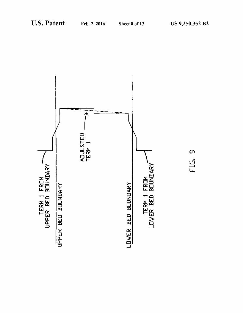
FIG. 9 is a plot with respect to depth of an adjusted or combined term 1 due to a first term 1 for an upper bed boundary and a second term 1 for a lower bed boundary in accord with one possible embodiment of the present inven tion.
FIG. 10 is a plot with respect to depth of a term 1, term 2, and transverse electric part due to an upper bed boundary and a term 1, term 2, and transverse electric part due to a lowerbed in accord with one possible embodiment of the present inven tion.
FIG. 11 is a schematic which shows an electromagnetic field produced by a transmitter and detected by a receiver as a Voltage, which has a proportional relationship to conduc tivity of a formation in a thickbed. However, the proportional relationship of Voltage to conductivity changes near a bed

US 9,250,352 B2 7
boundary, which change may be explained as a result of a transverse electric part, term 2, and term 3 induced near the bed boundary due to the electromagnetic field produced by the transmitter and detected by the receiver.
FIG. 12 is a plot with respect to depth wherein a derivative of a transverse electric part at a bed boundary is utilized to determine a new transverse electric part, which may then be utilized to invert a log in accord with one possible embodi ment of the present invention.
FIG. 13 is a simplified elevational view of a vertical mag netic dipole (VMD) at a distance Z in a bed with bound boundaries at-hand +h in accord with one possible embodi ment of the present invention.
FIG. 14 is a simplified elevational view of a horizontal magnetic dipole (HMD) at a distance Z in a bed with bound boundaries at-hand +h in accord with one possible embodi ment of the present invention.
DESCRIPTION OF PRESENTLY PREFERRED EMBODIMENTS
In approximating the effect of a tool crossing non-parallel bed boundaries, one embodiment of the present invention divides the problem into a series of the tool crossings of individual bed boundaries while maintaining the angle of the tool relative to each bed boundary. Referring now to the drawings and more particularly to FIG. 1, in this example, a tool moving through the hole or wellbore enters the middle bed at one angle and leaves at another because the upper and lower bed boundaries are non-parallel. The present invention is also operable of changing the angle of the tool within a bed and/or as the tool approaches or leaves a bed boundary. The effects of a change in angle of the tool may typically be more pronounced near the bed boundaries. In FIG. 1, the hole is assumed to be straight, but need not be. Referring to FIG. 2, when the tool is at the lower bed boundary, or point 1, a distance to the upper bed boundary may preferably be described by a line drawn perpendicular to the upper bed boundary. When the tool is at the upperbed boundary, or point 2, the distance to the lower bed boundary may preferably be described as a line drawn perpendicular to the lower bed boundary. In this example, the apparent thickness of the middle bed increases as the tool moves up hole. This makes real world Sense because the bed thickness is increasing to the right, referring to FIG. 2. In order to incorporate this aspect into one possible method of the present invention, it is desir able to have the thickness of the middle bed increase as the tool moves up hole, as discussed hereinafter.
Referring to FIG. 3, at an intermediate tool position in the middle bed, or point 3, the distance to the upperbed boundary and the distance to the lower bed boundary may be repre sented by drawing lines perpendicular to the respective bed boundaries, as indicated.
So when the tool is at point 3, the apparent thickness of the middle bed, as it would appear to the tool with parallel upper and lower bed boundaries, is shown as combination of these distances in FIG. 4. Accordingly, FIG. 4 shows the two bed boundaries as parallel and the two distances of FIG. 3 are added together, as illustrated. This apparent thickness changes as the tool moves. A computed log which is related to It of a vertical
magnetic dipole (VMD) in parallel beds (49) splits into 4 terms using P' (52) (see SPE84606 referenced hereinbefore). For convenience, equations may often be referenced herein by showing the equation number in parenthesis.
TMU
5
10
25
30
35
40
45
50
55
60
65
If = titlv2+ iv3 + 4 (54)(1) where
M 1 (55)(2) TMUI v. 32 (20-2) t 4t As (k32 + k23)(k12 + k21)e Jo (o)d
IU2 = (56)(3) My fres 1 (+(zo-h)+(z-h)) - (k32 + k23)(k12 -k21)e'2'0'" 'Jo (o)d 4t Jo Ah 2
IU3 = (57)(4) M, red 1 (-(z)-(-h))-(z-(-h))) 4t Jo Ang, (k32 -k23)(k12 + k21)e'2'0 do(O)d
and
IU = (58)(5) M, red 1 -(z-z)-42h 4t A, 32 - k3) (k12 -k2)eš2°0'e'52"Jo (o)d
O
Terms one (T1)
ityUI
and four (T4)
ityU4
are constants because the distance (Zo-Z) between the source at Zo, and receiver at Z is constant since the transmitter-receiver distance (Z-Z) is fixed at the manufacture of the tool. Terms two (T2)
TU2
and three (T3)
TU3 2
decay in the downward and upward directions respectfully. (See FIG. 5) When the beds are parallel, it is the perpendicular distance
of the transmitter at Zo, and receiver at Z relative to the bed boundary at +h that determines the T2 response note--(Z-h) and +(Z-h) in (3) and the bed boundary at -h that determines the T3 response note-(Zo-(-h)) and -(Z-(-h)) in (4). T4 because of the factore' is usually small and not shown. As one example, FIG. 13 and FIG. 14 shows a tool at a distance Zo from the center of a bed, with bed boundaries at +hand-h.
Associated with each bed and each bed boundary are four (4) terms. FIG.5 shows T1, T2, and T3 for a bed. FIG. 6 shows T1, T2, and T3 for a bed boundary. The fourth term may also be utilized but is typically less significant and is not shown. However, it may be utilized if desired.
For use with an electromagnetic logging tool, the transmit ter or source is a magnetic dipole. As indicated if FIG. 7, this magnetic dipole can be resolved into a vertical magnetic dipole (VMD) and a horizontal magnetic dipole (HMD). The

US 9,250,352 B2
VMD and HMD each split into 4 terms. The resolution is determined by the apparent dip angle of each bed boundary relative to the transmitter in the tool. As indicated in FIG. 8, one possible way to compute a log
in nonparallel beds is to compute the fields due to T3 of a VMD and of a HMD using a TM-TE split method due to the lowerbed boundary. The method involves changing the thick ness of the bed as the tool moves at the angle of the transmitter relative to the lower bed boundary. The method may then comprise computing the fields due to T2 of a VMD and a HMD for the upper bed boundary as the tool moves. Other steps may comprise changing the thickness of the bed as the tool moves at the angle of the transmitter relative to the upper bed boundary
Additional steps may comprise computing T1 and T4 due to the lower bed boundary as the tool moves while changing the thickness of the bed at the angle of the transmitter relative to the lower bed boundary. T1 and T4 may also be computed due to the upperbed boundary as the tool moves changing the thickness of the bed at the angle of the transmitter relative to the upper bed boundary.
If the bed is relatively thick, T4 is small and T1 from the upper bed boundary and lower bed boundary is typically the same at the middle of the bed. If the bed is relatively thin, T1 and/or T4 may not be the same at the middle of the bed. When this occurs it is necessary to adjust T1 and/or T4 so they are the same at the middle of the bed. One possible way to adjust T1 and T4 is to take a combination of T1 and T4 as the tool moves. This may be accomplished in many different ways with averaging techniques and the like. As one simple example, 100% of T1 and T4 may be taken when the tool is at the bottom of the layer. When the tool is at the middle, 50% may be taken from the bottom and 50% from the top. When the tool is at the top of the bed, 100% may be taken from the top of the layer.
In FIG. 9, T1 is adjusted or combined so that it provides continuous readings between the upper bed boundary and the lower bed boundary. After the adjustment is made, the log is computed by Summing the apparent dip corrected T3 from the bottom boundary. T2 from the top boundary and the adjusted or combined T1 and/or T4.
In one embodiment of the method for inverting a log, because the bed boundary angular effect is localized at a single bed boundary, the bed boundary angle of a single bed boundary can be varied until the computed log best matches the measured log. Abed boundary orientation can be changed by changing T1, T2, T3 and T4 for that bed boundary and recombining the terms. A bed boundary can be moved by shifting T1, T2, T3 and T4 associated with that bed boundary and recombining the terms.
It will be appreciated that the above method may also be utilized to detect the orientation and position of a tool for use in geosteering whereby it is often desirable to remain within a distance and at an orientation with respect to an upper bed boundary. As used herein, bed boundary may refer not only to two layers of rock but also to a fluid/fluid interface such as a water/oil interface, gas/liquid interface, or the like. Other uses may comprise detecting and orientating fractures. As Suggested by FIG. 10, a more accurate although slower
method to compute a log is to compute the transverse electric, (TE) part for a HMD and for a VMD (see equations (99) through (102)) and T3 of the transverse magnetic (TM) part for a HMD and for a VMD (see equations (4) and (57)) due to the lower bed boundary as the tool moves, changing the thickness of the bed as the tool moves at the angle of the transmitter relative to the lower bed boundary. Additional steps may comprise computing the TE part for a HMD and for
10
15
25
30
35
40
45
50
55
60
65
10 a VMD (see equations (76) through (79)) and T2 of the TM part for a HMD and for a VMD (see equations (3) and (56)) due to the upper bedboundary as the tool moves, changing the thickness of the bed as the tool moves at the angle of the transmitter relative to the upper bed boundary. The method may also utilize T1 for a HMD and a VMD (see
equations (2) and (55)) and T4 for a HMD and a VMD of the TM response (see equations (5) and (58)). Accordingly, the method may comprise computing T1 and/or T4 due to the lowerbed boundary as the tool moves, changing the thickness of the bed at the angle of the transmitter relative to the lower bed boundary. Additionally, T1 and T4 may be computed due to the upper bed boundary as the tool moves, changing the thickness of the bed at the angle of the transmitter relative to the upper bed boundary.
Similar to the discussion above, if the bed is relatively thick, T4 is small and T1 from the upper bed boundary and lowerbed boundary is typically same at the middle of the bed. If the bed is relatively thin, T1 and T4 might not be the same at the middle of the bed. When this occurs it is necessary to adjust T1 and T4 so they are the same at the middle of the bed. A way to adjust T1 and T4 is to take a combination of T1 and T4 as the tool moves. A way to do this is to take 100% of T1 and T4 from the bottom T1 and T4 when the tool is at the bottom. When the tool is at the middle take 50% from the bottom and 50% from the top T1 and T4. When at the top of the bed take 100% from the top T1 and T4 as before. (See FIG. 9)After the adjustment is made, the log may be computed by Summing the apparent dip corrected TE parts form the top and bottom, T3 from the bottom TM response, T2 from the top TM response and the adjusted T1 and T4 of the TM response.
Since this bed boundary angular effect is localized to a single bed boundary, the bed boundary angle of a single bed boundary can be varied until the computed log best matches the measured log. Abed boundary orientation can be changed by recomputing T1, T2, T3 and T4 of the TM part and the TE part associated with that bed boundary and recombining the parts as above. A bed boundary can be moved by shifting or recomputing T1, T2, T3, T4 of the TM part and the TE part associated with that bed boundary and recombining the parts as above.
Like the previously described method, this method may also be utilized to detect the orientation and position of a tool for use in geosteering whereby it is often desirable to remain withina distance and at an orientation with respect to an upper bed boundary. Other uses may comprise detecting and orien tating fractures. As Suggested by FIG. 11, the induction instrument per
forms a process on the geologic formation. The time varying current from the transmitter induces electromagnetic fields in the geologic formation. The electric field induces current via J=OE in the formation. This current in turn induces a voltage in the receiver. In some tools, the induced Voltage is directly related to the conductivity, O, of the geologic formation. At the middle of a thick bed, there is just T1 and this does not vary with angle. However, the relationship between induced Voltage and conductivity may change near bed boundaries. When there are bed boundaries, these bed boundaries induce T2, T3 and T4 of the TM response and the TE parts which occur only near bed boundaries. As shown by the equations and discussion hereinafter, it will be seen that the TE parts are directly related to the difference in the physical properties k-coue (20) between the upper and lower beds. The angle of the tool/hole relative to the formation is determined by the bed boundaries. One possible way to invert logs to obtain the actual material
properties may utilize thin bed material derivatives. A thin

US 9,250,352 B2 11
bed material derivative is the change or difference in a log when the actual material property
from equations (20) and (16), mainly the electrical conduc tivity O of a single thin bed changes. If the thin bed material derivatives for all of the beds are known, prior art methods can be utilized to obtain the actual material properties, assuming the bed boundaries are parallel. However, even with this assumption, prior art methods require that each derivative is a separate log which must be computed separately, which is very time consuming. The present method is much faster because the thin bed material derivatives are approximated, which reduces the time to invert a log to obtain the actual material properties based on utilizing k (see equation 20), as discussed hereinafter.
Accordingly, referring to equations (6) through (9) and/or equations (80) through (83), L' (for the case of the source in the middle or second layer L''' for a VMD for the upper (U) bed boundary at +h becomes:
The symbol ---- is used in this case to show the bed bound aries.
it' is proportional to the difference in material proper ties k-coue (20) (k-k) between the upper (equation (1)) and middle (equation (2)) beds. L.' for a HMD is similar. T' (equations (10) through (13)) and/or (equations
(103) through (106)) for the case of the source in the middle or second layer L' for a VMD for the lower (L) bed bound ary at -h becomes:
iTPL (103)(10) My, 2 2 2O'e-2S2h –2h M W - - - 2 81 (z-h) A 3-ki) ( e^'62se it "a locoda
-h
EE * (3 - k3) ce 20e-2S2h –22h (104(11) 2 - 42 3, AA,
10
15
25
30
35
40
45
50
55
60
65
12 -continued
M, (-2Q'e 2" (105)(12) = (ki-ki) o Ah Ay
{(a + 1)eš2") + (62 - 1)eš2''x AJo(Ap)d a
- - - in
- My ce 20e-2S2h (106)(13)
T' proportional to the difference in material properties k-coue (20) (k-k) between the middle (equation (2)) and lower (equation (3)) beds. L' for a horizontal magnetic dipole (HMD) is similar. Fort' (at 'at'it'), (k-k) is outside the
integral and for L' ('L'. It', '), (k-k) is outside the integral. Since the difference ink is a constant, it is outside the integral in both cases Ifkofa bedchanges, the difference in k of the bed boundary above (k-k) and below (ka-k') changes. This will change the TE parts for the Upper (U) part of L', 'L' and the Lower (L) part of
E. E. at at r.
This difference in k is useful in inverting logs because it allows the thin bed material derivatives to be approximated. This difference or change in the TE part approximates a thin bed material derivative, so one method involves computing the TE integrals without the difference ink. The new differ ences in k are computed, and the new TE part is computed. The old TE part may be subtracted from the new TE parts to compute the approximate material derivatives. This provides for a very quick computation of material derivatives.
FIG. 12 shows a visual example of the new TE part and the old TE part for the upperbed boundary at +h. The method may comprise doing the same thing for the lower bed boundary at -h.
Accordingly, the method may use the material derivatives to invert the log, to obtain the actual material properties
(equations (20) (16)). The convergence criterion used to stop the iteration process
varies with the situation. If a rough estimate is required, a 10 (ten) percent difference between the measure and computed result might be sufficient. If a better result is required a 1 (one) percent difference might be required.
Accordingly, one embodiment of the method allows quickly changing a log by changing a constant involving k. Electromagnetic Fields Due to a Vertical Magnetic Dipole
For sinusoidally time-varying fields with time variation taken as e", Maxwell's equations take the form
and
VxE=iouH+iouM. (15)
It is assumed that the only source in the medium is a magnetic dipole with dipole moment, M. The complex permittivity e. in equation (14) is:

US 9,250,352 B2 13
e = c + i. (16)
where E' is the dielectric permittivity and O is the electrical conductivity of the medium.
It can be shown that if a vector potential function, which may be called the Hertz vector potential L, is introduced, then
E=iouVxII, (17)
and
where
k’=cole. (20)
Now consider the vertical magnetic dipole (VMD) shown in FIG. 13. Due to the rotational symmetry about the Z-axis of the geometry, the cylindrical coordinate system is used. The magnetic dipole is located at x=0, y=0, or p=0 and ZZ, and pointing in the Z direction, while the bed boundaries are at ZF-th.
For a VMD, equation (19) reduces to a scalar equation. V’L+k L=-Mö(r-zož), (21)
where M is the vertical component of the total dipole moment M. The particular solution of equation (21) is to
M 1 (22) it. = Y ?e - a coda, where Jo is the Zero order Bessel function of the first kind and
3-(2-k2)/2. (23)
The branch of S is so chosen that S-W as w approaches infinity and S=-ik for w=0. The components of the electromagnetic field are:
E = -i ot. (24) a = -tous,
from (17) and
it did. did". (25) = T = T, from (18). To satisfy the boundary condition on tangential E. E. and H. H. at Z th, the following boundary conditions must be satisfied. From equation
Ji-i-1) (26)
and from equation (25):
dit: dit-i-1) (27) d : T. d:
5
10
15
25
30
35
40
45
50
55
60
65
14 The above boundary conditions are enforced at Zh for j=1
and at Z-h for j=2. It of a VMD, can be expressed in terms of L' which is mathematically transverse magnetic (TM) and L' which is physically transverse electric (TE):
at - TM-TE. (28)
JL' is physically TE because the E field using E-icouVx (L'2) (17) is in the x and y directions, which are transverse to the Z axis. Therefore, (L'+'t') is physically TE.
Restating the boundary conditions for at assuming L1-L2 Lll.
- t-(+1) (26)(29)
dit- d -(+1) (27)(30) d : T. d:
Let the equivalent boundary conditions on t' and it' be:
TE TE dit; di?ti) (31) d: d: T T dit; dt, 1) (32)
d: d: E if TE t" + i = 7:1) + (i-1) (33)
T T Xji - V(i+1). (i.1). (34)
Note that equation (33) is equivalent to (26) or (29) using (28). Equation (31) plus (32) is equivalent to (27) or (30) again using (28). X, in (34) can be anything, such as ki. Setting x, to be k? in (34). Thus the equivalent boundary conditions (31) through (34) become:
drif dit?, (31)(35) d: d:
dri' dril, (32)(36) d: d:
kit. = k1721. (38)
Restating the boundary conditions, equation (37) is equiva lent to (26) or (29) using (28). (35) plus (36) is equivalent to (27) and (30) again using (28). The above boundary condi tions (35) through (38) are enforced at Zh for i=1 and at z=-h for j=2. The Hertz potential It'? satisfies the inhomogeneous par
tial differential equation (19) with MMö(r-Z2)2. Accord ingly L' can be expressed as:
TM My (39) *:I = 4, , teil-oli Pei'a (pda g
US 9,250,352 B2
-continued
in M. f. flee 2-0 + O.e :(-h) + (40) T3" = 4 82 do(O)d
7. O PeS2(z+h)
- - - -h
M, fre 41 it?' = O fest to + Qe 36tha.J. (Ap)da (41)
The symbol ---- is used in this case to show the bed bound aries at th, and later to show the position of the source at Zo (see equations between (49) and (50)). Because the source could be in any of the three layers, the Bs are flags that indicate in which medium the source is located. For example, if the Source is in the middle or second medium, B-1 and B-B 0. By applying the boundary conditions (see equations (36) and (38)), we obtain four equations to solve for the four unknown functions P.O.P. and Q.
For the case of the source in the middle or second layer b = 1:
For the case of the source in the middle or second layer f=1, the middle layer splits into an upper (U) part where Z>zo.T.', and a lower (L) part where Z-Zo.T.'":
co-22h (48) TM v. -(z-h) t 47t O Ahé2 P2k22e Jo (o)d
- - - h O
Tu My (49) 73 4t
co-22h P(ki + k)e 3' + (ki-ki.e. "J. Opda o Ahé2
- - - 30 O
ca-2-h TML My 252 (50) 2 4t J. A.
10
15
25
30
35
40
45
50
55
60
65
Using P' (52), t' (49) splits into four (4) terms. For the case of the source in the middle or second layer B-1:
If = titlv2+ iv3 + 4 (1)(54) where
M 1 (2)(55) IU = 4t A, 32 + k23)(k12 + k21)eš20’AJo (Ap)da
IU2 = (3)(56) M, red 1 -)--(z- (k32 + k23)(k12 -k2)eš2'-0" 'AJo (Ap).d. 4t Jo Ah.
it'3 = (4)(57)
My ? 1 (k32 - k3)(k1 + k2)eš2:0'AJo (Ap)d a 47, Jo Ahi
and
tly 4 = (5)(58) M
The above equations apply when the both the Source at Zo and the receiver at Z are in the middle bed. Four terms are present when the source and receiver are in different beds, although term one (1) and term four (4) are not constants.
Similarly 1,' (see equation (50)) splits into 4 terms using Q' (see equation (53)). Of the four terms, term one is the one that is most like a
complete log. If only one term were to be computed, it should be term one. It is also useful in computing other terms. For example, if term two in MWD were required it could be computed by computing a log with terms one and two then subtracting term one form the log. This is useful in MWD because phase differences and/or amplitude ratios are mea Sured. The boundary condition on (L'+'t') (37) may be
thought of as a coupling mechanism between L' and it'. The homogeneous solution of equation (21) having cylindri cal symmetry about the Z-axis is:
cas,(A)es (th (59) TE 4 - 4), a lot.
Therefore, L' in each of the three layers for a VMD is:
My cx 60) -81 (z-h) ( 47 Jo Se Jo (o)d,

US 9,250,352 B2
-continued My fre 61 a; - i? creat" seat") coda, (61)
- - -h
M, fre 62 i? = I. Tea"Joopda. (62)
Substituting equations (39) through (41) and (60) through (62) into boundary conditions (35) and (37), we obtain the solutions for S.T.S. and T:
For the case of the source in the middle or second layer
2P 252h (68) P = Ah (ki - k3)
69 Q32 = Aston -- Qs A slot + Qe 2 + P. (69) 3 2
For the case of the source in the middle or second layer
2O'e 22h (70) Q32 = Ah (k3 -k3)
From equations (63) to (66) note that S.T. S. and T split into an upper (U) part S.T., S. and T, and a lower (L) part S, T, S, and T. Consequently, L' splits into an upper (U) part t' associated with the upper bed boundary at Zhanda lower (L) part L'associated with the lowerbed boundary at z=-h such that:
at TE-ITE-ITEL, (71) For the upper (U) part:
S=P, SH". A (72)
S.--P,3e (3-3)/A, (74)
T=-Pse 2.5225/A (75) from (63) through (66).
18 TE. The upper (U) part of w is:
My fes P1 M W (76)
5 iF = , sh'ei "a locoda - - h
-M, reo P. (£2 + 3)e^2 + (77) it: = 47t allo (p)d
10 0 Av (2-3)eš2
- M - P1 ({2 + £3)eš2") + (78) ? le2s2fg Jo (o)d 4t Jo Ay (g -g,)eš2th)
-h 15
-M, fre P 79 t" -- I es'62ses'"a coda (79) J Jo Ay
20 For the case of the source in the middle or second layer, B=1 using P. (68) at 'becomes:
M coppe-22h M W (6)(80)
ti" = (ki-ki) ? -sh'ei "xU(pda - h
IFU - M. (k -ki) 2p–2:2h (7)(81) 22 412, AA,
30 {({2 + £3)e^2 + (62 – £3)eš2" x AJo (Ap)d a
- My pe-22h (8)(82) = - (ki - k3) ? e-2s2h 47t o AyAh {(a + £3)eš2") + (82–83)eš2" x AJo(Ap)d a
35
- - -h
It = (9)(83) - My pe-22h
40 A (i-ki.. I es'62ses"xacoda
It is the difference in material properties k-coue (20) (k-k) at Zh that drives the L' part of a VMD. Simi
As larly for t' for a HMD. Using P' (52) 'L' (7) and (81) splits into 4 terms
iA il, tie ii iii.21 JL2
so where, for the case of the source is in the middle or second layer B-1:

US 9,250,352 B2
FE (113) E = icopt -, and dy
(dit dict (114) E = ice is dy } from (17) and H = d W d (115) y dy 7t), an
d 116 H = k1 + (V. It) (116) dy
from (18).
To ensure continuity of the tangential E and H field com ponents across the bed boundaries at Z-th, the following boundary conditions on the Hertz potential must be satisfied, assuming Li Ll2 Lls LL.
from (113) t; it?; 1) (117)
drill dri, (118) from (114) and (117) - = } d d
from (115) V. It = V . It, and (119)
from (116) and (119) kit' = kitc. (120)
The Hertz potential 'satisfies the inhomogeneous par tial differential equation (19) with MMö(r-Z2)x. Accord ingly, L' can be expressed as:
fea 121 it = i Elesi to + Pe*(hal (Ap)da, (121) 4t Jo lé - h
M, cx Pee-to-to -- (122) it. = 82 Jo (o)d,
"Jo O.e. 2 (-h)+ Pes2G+h) -h
Mh, f f33 (123) TM 12-32-20 83 (z+h) *3 - 4 J, se + Q3e Jo(Ap)da.
P,QPQ (42) through (45) are from boundary conditions (120) and (118).
it, alone cannot satisfy the boundary condition on V:Jt. (119). This boundary condition may be thought of as a cou pling mechanism between L,' and L' (112). It' in each of the three layers is:
cx 124
IF Acost? SeSI A(p)da, (124) - h
cx 125 it: = Ecost ? (Tef:(-h) + Set:Cth), (pda. ' - -h
TE (126)
Substituting equations (121) through (123) and (124) through (126) into boundary conditions (117) and (119), we obtain the solutions for S.T.S. and T
10
15
25
30
35
40
45
50
55
60
65
From equations (127) to (130), it is noted that S.T. S. and T. split into an upper (U) part S. T. S. and T and a lower (L) part S, T, S, and T. Consequently, L' splits into an upper (U) part t' associated with the upper bed boundary at Zhanda lower (L) part L'associated with the lower bed boundary at z=-h such that:
a TE-ITEU-TEL. (133)
Very similar to (71) for a VMD. The boundary conditions for a Vertical Electric Dipole are
(See Sommerfeld 1949 hereinbefore):
kit. kill?.g. 1) (134)
dit- d -(+1) (135) d: d:
The above boundary conditions can be written as:
it. = I, (136)
diff di?, (137) d: d:
ki(t + i) = k1 (it i + v ) (138)
dril." dri. (139) d : T dz,
(138) is equivalent to (134) and (137) plus (139) is equiva lent to (135) using at L'+'t'.
For completeness, the boundary conditions for a Horizon tal Electric Dipole are:
2TE 2 TE kit) = k +1)7; 1) (140) TE TE
k2 dit: = k. di?ti) (141) - d. (i+1) d
2 2 T kit = k +1)7:1) (142)
W. H. W. It (143)
While the invention has been described in terms of com ponents of various methods, individual components or vari ous groups of components of the methods described herein before can be utilized. For example, in one embodiment, it may be useful to utilize transverse magnetic term one by itself. Alternatively, it may be useful to determine selected terms for particular boundaries. Other examples are provided

US 9,250,352 B2 23
above and in the claims. The invention can be implemented by first determining what happens at the boundaries. Alterna tively, the invention may first calculate a log for each layer. Combinations of these approaches may also be utilized.
While the invention has been described in terms of meth ods, it will be appreciated that the methods may be utilized within devices, whereby the invention also describes physical devices. Thus, the present invention may be embodied as a machine or system for producing logs. Raw or transformed electrical signals detected by the system are transformed to describe material properties of beds, bed boundary orienta tions and positions, which may not be apparent or may be inaccurate when simply viewing the electrical signals. It is well known that material properties of beds, bed boundary orientations and positions often have inaccuracies at the bed boundaries. For example, instead of a claim to a method, the present invention might also be described and claimed, refer ring to claims hereinafter, as a system making a log of mate rial properties in a plurality of beds from an instrument which produces an electromagnetic field, wherein the system com prises one or more electronic components programmed for estimating material properties for said plurality of beds, esti mating positions for a plurality of bed boundaries, estimating orientations for said plurality of bed boundaries wherein said bed boundary orientations are individually variable, and uti lizing said positions, said orientations, and said material properties to compute said log. As well, the invention may comprise software which may
be stored on a storage medium and utilized in a computer memory, and/or implemented as a series of instructions, depending on the programming language utilized. For example, the invention may be implemented in Fortran or many other Suitable computer languages. As discussed above, it is noted once again that transverse
electric down or transverse electric up is not the same as transverse electric terms one, two, three or four.
While the present invention is described in terms of a geological layered environment and electromagnetic tools, the invention may also be utilized for other purposes, e.g., medical purposes such as acoustic analysis of a human body, seismic analysis, or other tools and layered environments. The wave equations are useful for acoustic wave analysis, utilizing higher and/or lower frequencies, and the like within other layered environments.
Accordingly, the foregoing disclosure and description of the invention is illustrative and explanatory thereof, and it will be appreciated by those skilled in the art, that various changes in the ordering of steps, ranges, and/or attributes and param eters related to the steps and/or materials, as well as in the details of the illustrations or combinations of features of the methods discussed herein, may be made without departing from the spirit of the invention. Thus, while the invention has been described in connection with a preferred embodiment, it is not intended to limit the scope of the invention to the particular form set forth, but on the contrary, it is intended to cover Such alternatives, modifications, and equivalents as may be included within the spirit and scope of the invention. What is claimed is: 1. A method for making a log of material properties in a
plurality of beds from an instrument which produces an elec tromagnetic field while moving through aborehole producing data correlated to depth in said borehole, comprising:
utilizing at least one computer memory during the follow ing steps wherein said data is produced by said instru ment while moving through said borehole;
estimating material properties for said plurality of beds; estimating positions for a plurality of bed boundaries;
10
15
25
30
35
40
45
50
55
60
65
24 estimating orientations for said plurality of bed boundaries
wherein said bed boundary orientations are individually variable; and
utilizing said positions, said orientations, and said material properties to compute said log; wherein estimating materials properties comprises receiving data
representing measurement resulting from the electro magnetic field as a function of depth of the instrument in the borehole, and
estimating said orientations comprises for each of the plurality of bed boundaries, fitting at
least one of a magnetic or electric dipole function to said data,
adjusting the fit of said at least one for adjacent bed boundaries in order to minimize discontinuity of the fit of said at least one for the adjacent bed boundaries, and
for each of the plurality of bed boundaries, selecting a relative dipping angle dependent on the adjusted fit, to thereby vary estimates of said bed boundary orientations in a manner not constrained to be par allel, and
utilizing comprises computing said log dependent on the selected relative dipping angle for each of the plural ity of bed boundaries.
2. The method of claim 1 comprising: varying said orientation for a selected one of said plurality
of bed boundaries; and utilizing said orientation, said positions, and said material
properties to compute said log. 3. The method of claim 1 comprising: varying a position for a selected one of said plurality of bed
boundaries; and utilizing said orientations, said position, and said material
properties to compute said log. 4. The method of claim 1 wherein an inversion process is
utilized to invert said log. 5. The method of claim 1 comprising: varying said material properties for a selected one of said
plurality of beds; and utilizing said orientations, said positions, and said material
properties to compute said log. 6. The method of claim 1 comprising: selecting a bed boundary from said plurality of bed bound
aries; computing a transverse magnetic term one; and utilizing said transverse magnetic term one to compute said
log. 7. The method of claim 6 comprising: computing a transverse magnetic term two, and a trans
verse magnetic term three for said bed boundary; and utilizing said transverse magnetic term one, said transverse
magnetic term two, and said transverse magnetic term three to compute said log.
8. The method of claim 1 comprising: selecting a bed from said plurality of beds wherein said bed
has an upper bed boundary and a lower bed boundary; computing a first transverse magnetic term one for said
upper bed boundary; computing a second transverse magnetic term one for said
lower bed boundary; combining said first transverse magnetic term one and said
second transverse magnetic term one to provide a com bined transverse magnetic term one; and
utilizing said combined transverse magnetic term one to compute said log.
US 9,250,352 B2 25
9. The method of claim 8 comprising: computing a transverse magnetic term two for said upper bed boundary;
computing a transverse magnetic term three for said lower bed boundary; and
utilizing said combined transverse magnetic term one, said transverse magnetic term two, and said transverse mag netic term three to compute said log.
10. The method of claim 1 comprising: selecting a bed boundary from said plurality of bed bound
aries; computing a transverse electric term one; and utilizing said transverse electric term one to compute said
log. 11. The method of claim 10 comprising: computing a transverse electric term two, and a transverse
electric term three for said bed boundary; and utilizing said transverse electric term one, said transverse
electric term two, and said transverse electric term three to compute said log.
12. The method of claim 1 comprising: selecting a bed from said plurality of beds wherein said bed
has an upper bed boundary and a lower bed boundary; computing a first transverse electric term one for said upper bed boundary;
computing a second transverse electric term one for said lower bed boundary;
combining said first transverse electric term one and said second transverse electric term one to provide a com bined transverse electric term one; and
utilizing said combined transverse electric term one to compute said log.
13. The method of claim 12 comprising: computing a transverse electric term two for said upperbed
boundary; computing a transverse electric term three for said lower bed boundary; and
utilizing said combined transverse electric term one, said transverse electric term two, and said transverse electric term three to compute said log.
14. The method of claim 1 comprising: selecting a bed boundary from said plurality of bed bound
aries; computing a transverse electric up for said bed boundary; computing a transverse electric down for said bed bound
ary; and utilizing said transverse electric up, and said transverse
electric down to compute said log. 15. The method of claim 14 comprising: computing a transverse magnetic term one; and utilizing said transverse magnetic term one, said transverse
electric up, and said transverse electric down to compute said log.
16. The method of claim 14 comprising: computing a transverse magnetic term one, a transverse
magnetic term two, and a transverse magnetic term three for said bed boundary; and
utilizing said transverse magnetic term one, said transverse magnetic term two, said transverse magnetic term three, said transverse electric up, and said transverse electric down to compute said log.
17. The method of claim 1 comprising: selecting a bed from said plurality of beds wherein said bed
has an upper bed boundary and a lower bed boundary; computing a transverse electric down for said upper bed
boundary;
10
15
25
30
35
40
45
50
55
60
65
26 computing a transverse electric up for said lower bed
boundary; and utilizing said transverse electric down and said transverse
electric up to compute said log. 18. The method of claim 17 comprising: computing a first transverse magnetic term one for said
upper bed boundary; computing a second transverse magnetic term one for said
lower bed boundary; combining said first transverse magnetic term one and said
second transverse magnetic term one to provide a com bined transverse magnetic term one; and
utilizing said combined transverse magnetic term one, said transverse electric up, and said transverse electric down to compute said log.
19. The method of claim 17 comprising: computing a first transverse magnetic term one for said
upper bed boundary; computing a second transverse magnetic term one for said
lower bed boundary; combining said first transverse magnetic term one and said
second transverse magnetic term one to provide a com bined transverse magnetic term one;
computing a transverse magnetic term two for said upper bed boundary;
computing a transverse magnetic term three for said lower bed boundary; and
utilizing said combined transverse magnetic term one, said transverse magnetic term two, said transverse magnetic term three, said transverse electric up, and said trans verse electric down to compute said log.
20. The method of claim 6 comprising: computing a transverse electric up and a transverse electric down for said bed boundary;
computing a new transverse electric up for said bed bound ary:
computing a new transverse electric down for said bed boundary; and
utilizing said transverse magnetic term one, said new trans verse electric up and said new transverse electric down to compute said log.
21. The method of claim 7 comprising: computing a transverse electric up and a transverse electric down for said bed boundary;
computing a new transverse electric up for said bed bound ary:
computing a new transverse electric down for said bed boundary; and
utilizing said transverse magnetic term one, said transverse magnetic term two, said transverse magnetic term three, said new transverse electric up and said new transverse electric down to compute said log.
22. The method of claim 8 comprising: computing a transverse electric down for said upper bed
boundary; computing a new transverse electric down for said upper
bed boundary; a-Fid computing a transverse electric up for said lower bed
boundary; computing a new transverse electric up for said lower bed
boundary; and utilizing said transverse magnetic term one, said new trans
verse electric down and said new transverse electric up to compute said log.
23. The method of claim 8 comprising: computing a transverse electric down for said upper bed
boundary;

US 9,250,352 B2 27
computing a new transverse electric down for said upper bed boundary;
computing a transverse electric up for said lower bed boundary;
computing a new transverse electric up for said lower bed boundary; and
utilizing said combined transverse magnetic term one, said transverse magnetic term two, said transverse magnetic term three, said new transverse electric down and said new transverse electric up to compute said log.
24. The method of claim 1 comprising: determining a change in a transverse electric part to esti
mate material property derivatives for said plurality of beds; and
estimating new material properties for said plurality of beds using said material property derivatives for said plurality of beds.
25. The method of claim 24 comprising: iterating the above steps until a convergence criteria is
reached. 26. The method of claim 24 wherein said transverse electric
part comprises an upper bed boundary term and a lower bed boundary term for each of said plurality of beds.
27. The method of claim 24 wherein said transverse electric part is a transverse electric part of a dipole.
10
15
28 28. The method of claim 27 wherein said dipole is a vertical
dipole. 29. The method of claim 27 wherein said dipole is a hori
Zontal dipole. 30. The method of claim 24 wherein a change in a constant
related to said material property in said transverse electric part is utilized for determining said bed material derivatives.
31. The method of claim 30 wherein said constant is described utilizing k, where k is coue.
32. The method of claim 1 wherein said plurality of bed boundaries comprise non-parallel bed boundaries.
33. The method of claim 1 comprising geo-steering said instrument relative to a first bed boundary.
34. The method of claim 33 comprising determining an orientation between said instrument and said first bed bound ary.
35. The method of claim 33 comprising determining a relative position between said instrument and said first bed boundary.
36. The method of claim 1 comprising estimating apparent dip angles for said plurality of bed boundaries wherein said estimation of said apparent dip angles assumes that said apparent dip angle is changing within a selected one of said plurality of beds.