Embed Size (px)
Citation preview
USOO83203 01B2
(12) United States Patent (10) Patent No.: US 8,320,301 B2 Walton et al. (45) Date of Patent: Nov. 27, 2012
(54) MIMO WLAN.SYSTEM 5,471,647 A 11/1995 Gerlach et al. 5,479,447 A 12/1995 Chow et al. 5.493.712 A 2f1996 Ramesh et al.
(75) Inventors: J. Rodney Walton, Carlisle, MA (US); 5.506,861. A 4/1996 Bottoml Mark S. Wallace, Bedford, MA (US); - WW Conti O s ey John W. Ketchum, Harvard, MA (US); (Continued) Steven J. Howard, Ashland, MA (US) FOREIGN PATENT DOCUMENTS
(73) Assignee: Qualcomm Incorporated, San Diego, AU 2002259221 11, 2002 CA (US) (Continued)
(*) Notice: Subject to any disclaimer, the term of this OTHER PUBLICATIONS patent is extended or adjusted under 35 “Broadband Radio Access Networks (BRAN); HIPERLANType 2: U.S.C. 154(b) by 1738 days. Data Link Control (DLC) Layer; Part 1: Basic Data Transport Func
tions.” ETSI Standards, European Telecommunications Standards p (21) Appl. No.: 10/693.419 Institute BR(V131): 1-88 (Dec. 2001).
(22) Filed: Oct. 23, 2003 (Continued)
(65) Prior Publication Data Primary Examiner — Marcus R Smith (74) Attorney, Agent, or Firm — Qualcomm Incorporated;
US 2004/OO82356 A1 Apr. 29, 2004 Thien T. Nguyen; James H. Yancey, Jr.
Related U.S. Application Data (57) ABSTRACT
(60) gyal application No. 60/421,309, filed on Oct. A multiple-access MIMO WLAN system that employs s MIMO, OFDM, and TDD. The system (1) uses a channel
(51) Int. Cl structure with a number of configurable transport channels, ioiv.4/00 (2009.01) (2) Supports multiple rates and transmission modes, which are H04L 7/02 (200 6,015 configurable based on channel conditions and user terminal
in capabilities, (3) employs a pilot structure with several types of (52) U.S. Cl. ........ . 370/328, 370/338; 3.75/276; 375/347 pilot (e.g., beacon, MIMO, steered reference, and carrier (58) Field of Classification Search ............... ... ... None pilots) for different functions, (4) implements rate, timing,
See application file for complete search history. and power control loops for proper system operation, and (5) (56) References Cited employs random access for system access by the user termi
U.S. PATENT DOCUMENTS
nals, fast acknowledgment, and quick resource assignments. Calibration may be performed to account for differences in the frequency responses of transmit/receive chains at the
4,736,371 A 4/1988 Tejima et al. access point and user terminals. The spatial processing may 4,750,198 A 6/1988 Harper then be simplified by taki dvant f th 1 4,797,879 A 1, 1989 Habbab et al. en be simplied by taking advantage or une reciproca 5,241,544 A 8/1993 Jasper et al. nature of the downlink and uplink and the calibration. 5,295,159 A 3/1994 Kerpez 5,404,355 A 4, 1995 Raith 30 Claims, 23 Drawing Sheets
f
300a -1
1 TDD Frame --> 310 320 330 340 350 BCH FCCH FCH RCH RACH .
Segment Segment Segment Segment Segment f f \
f f s i
Time
f
A 410 f 420 f 430a 430b 490m 440a 440b 44On 450 BCH FCCH FCH FCH FCH RCH RCH RCH RACH PDU PDU PDU 1 PDU 2 ||PDUN PDU 1 | PDU 2 ||PDUN, PDU(s)
K-T-> E. FCHLength -i- RCHLength — EP FCH RCH bist offset k ECH-> k-ROH->
Offset 3 Offset 3

US 8,320,301 B2 Page 2
5,509,003 5,606,729 5,638,369 5,677,909 5,729,542 5,790,550 5,818,813 5,822,374 5,832,387 5,859,875 5,867.478 5,883,887 5,886,988 5,959,965 5,973,638 5,982,327 6,049,548 6,067,290 6,072,779 6,084.915 6,097,771 6,115,354 6,122.247 6,131,016 6,141,388 6,141,542 6,141,567 6,144,711 6,163,296 6,167,031 6,178,196 6,205,410 6,222,888 6,232,918 6,266,528 6,275,543 6,278,726 6,292,917 6,298,035 6,298,092 6,308,080 6,314,113 6,314,289 6,317,612 6,330,277 6,330,293 6,330.462 6,333,953 6,339.399 6,345,036 6,346,910 6,348,036 6,351,499 6,363,267 6,377,812 6,385,264 6.426,971 6,452.981 6.463,290 6,473,467 6,478,422 6,492.942 6,510, 184 6,515,617 6,532,225 6,532,562 6,545,997 6,574,211 6,574.267 6,574,271 6,594.473 6,594,798 6,597.682 6,608,874 6,611,231 6,615,024 6,631,121 6,636,496
U.S. PATENT DOCUMENTS
4, 1996 2, 1997 6, 1997
10, 1997 3, 1998 8, 1998
10, 1998 10, 1998 11, 1998 1, 1999 2, 1999 3, 1999 3, 1999 9, 1999
10, 1999 11, 1999 4, 2000 5, 2000 6, 2000 T/2000 8, 2000 9, 2000 9, 2000
10, 2000 10, 2000 10, 2000 10, 2000 11, 2000 12, 2000 12, 2000
1, 2001 3, 2001 4, 2001 5, 2001 T/2001 8, 2001 8, 2001 9, 2001
10, 2001 10, 2001 10, 2001 11, 2001 11, 2001 11, 2001 12, 2001 12, 2001 12, 2001 12, 2001
1, 2002 2, 2002 2, 2002 2, 2002 2, 2002 3, 2002 4, 2002 5, 2002 T/2002 9, 2002
10, 2002 10, 2002 11, 2002 12, 2002
1, 2003 2, 2003 3, 2003 3, 2003 4, 2003 6, 2003 6, 2003 6, 2003 T/2003 T/2003 T/2003 8, 2003 8, 2003 9, 2003
10, 2003 10, 2003
Snijders et al. D'Amico et al. Ayerst et al. Heide Dupont Peeters et al. Saito et al. Levin Bae et al. Kato et al. Baum et al. Take et al. Yun et al. Ohkubo et al. Robbins et al. Vook et al. Bruno et al. Paulrajetal. Tzannes et al. Williams Foschini Weck Levin et al. Greenstein et al. Servais et al. Kotzin et al. Youssefimir et al. Raleigh et al. Lier et al. Olofsson et al. Naguib et al. Cai Kao et al. Wax et al. Farzaneh Petrus et al. Mesecher et al. Sinha et al. Heiskala Heath et al. Burt et al. Guemas Eberlein et al. Farsakh Gelblum et al. Klank et al. Chen Bottomley et al. Andersson et al. Sudo et al. Ito Looney et al. Paulrajetal. Lindskog et al. Rashid-Farrokhi et al. Terasawa et al. Wu et al. Raleigh et al. Stilp et al. Wallace et al. Hansen Kezys Okamura Demers et al. Chang et al. Chou et al. Bohnke et al. Padovani et al. Kanterakis et al. Mesecher et al. Dabak et al. Chou et al. Kari Beidas et al. Crilly, Jr. et al. Boros et al. Yoon Cho et al.
6,636,568 6,654,590 6,654,613 6,668, 161 6,683,916 6,690,660 6,693,992 6,697,346 6,711,121 6,728,233 6,731,668 6,735,188 6,738,020 6,744,811 6,751,187 6,751,444 6,751.480 6,757,263 6,760,313 6,760,388 6,760,882 6,768,727 6,771,706 6,785,341 6,785,513 6,788,948 6,792,041 6,795,424 6,798,738 6,801,790 6,802,035 6,804,191 6,821,535 6,842,460 6,847,828 6,850,252 6,850,498 6,859,503 6,862,271 6,862.440 6,868,079 6,873,651 6,879,578 6,879,579 6,885,708 6,888.809 6,888,899 6,891,858 6,920, 192 6,920, 194 6,927,728 6,937,592 6,940,917 6,950,632 6,952.426 6,952.454 6.956,813 6.956,906 6.959,171 6,963,742 6,965,762 6,980,601 6,980,800 6,985.434 6,985,534 6,987,819 6,990,059 6,992,972 6,996,380 7,002,900 7,003,044 7,006.464 7,006,483 7,006,848 7,009,931 7,012,978 7,020,110 7,020,482 7,020,490
10, 2003 11/2003 11/2003 12, 2003
1, 2004 2, 2004 2, 2004 2, 2004 3, 2004 4, 2004 5, 2004 5, 2004 5, 2004 6, 2004 6, 2004 6, 2004 6, 2004 6, 2004 T/2004 T/2004 T/2004 T/2004 8, 2004 8, 2004 8, 2004 9, 2004 9, 2004 9, 2004 9, 2004
10, 2004 10, 2004 10, 2004 11, 2004 1/2005 1/2005 2, 2005 2, 2005 2, 2005 3, 2005 3, 2005 3, 2005 3, 2005 4, 2005 4, 2005 4, 2005 5/2005 5/2005 5/2005 7/2005 7/2005 8, 2005 8, 2005 9, 2005 9, 2005
10, 2005 10, 2005 10, 2005 10, 2005 10, 2005 11/2005 11/2005 12, 2005 12, 2005
1, 2006 1, 2006 1, 2006 1, 2006 1, 2006 2, 2006 2, 2006 2, 2006 2, 2006 2, 2006 2, 2006 3, 2006 3, 2006 3, 2006 3, 2006 3, 2006
Kadous Boros et al. Maeng et al. Boros et al. Sartori et al. Kim et al. Jones et al. Halton et al. Gerakoulis et al. Park et al. Ketchum Becker et al. Lindskog et al. Kantschuk Walton et al. Meiyappan Kogiantis et al. Olds Sindhushayana et al. Ketchum et al. Gesbert et al. Sourour et al. Ling et al. Walton et al. Sivaprakasam Lindskog et al. Kim et al. Kapoor et al. Do et al. Rudrapatna Catreux et al. Richardson Nurmi et al. Olkkonen et al. Miyoshi et al. Hoffberg Heath et al. Pautler et al. Medvedev et al. Sampath Hunt Tesfai et al. Pan et al. Myles et al. Thomas et al. Foschini et al. Raleigh et al. Mahesh et al. Laroia et al. Stopler et al. Vook et al. Heath, Jr. et al. Menon et al. Yun et al. Wu et al. Jalali et al. Fukuda Tager et al. Tsien et al. Boros et al. Sugar et al. Jones Noerpel et al. Wu et al. Meister Thomas et al. Anikhindi et al. Van Nee Dent Walton et al. Subramanian et al. Gopalakrishnan etal Nelson, Jr. et al. Ling et al. Ma et al. Talwar Walton et al. Medvedev et al. Khatri
370,328

US 8,320,301 B2 Page 3
7,023,826 B2 * 4/2006 Soberg et al. ................ 370,338 7.551,546 B2 * 6/2009 Ma et al. ....................... 370,208 7,031,671 B2 4/2006 Mottier 7,551,580 B2 6/2009 du Crest et al. 7,035,359 B2 4/2006 Molnar et al. 7,573,805 B2 8/2009 Zhuang et al. 7,039,125 B2 5, 2006 Friedman 7,599.443 B2 10/2009 Ionescu et al. 7,042,858 B1 5, 2006 Ma et al. 7,603,141 B2 10/2009 Dravida 7,054,378 B2 5, 2006 Walton et al. 7,606,296 B1 10/2009 Hsu et al. 7,058,367 B1 6, 2006 Luo et al. 7,606,319 B2 10/2009 Zhang et al. 7,062,294 B1 6/2006 Rogard et al. 7,623,871 B2 11/2009 Sheynblat 7,068,628 B2 6, 2006 Li et al. 7,636,573 B2 12/2009 Walton et al. 7,072,381 B2 7/2006 Atarashi et al. 7,653,142 B2 1/2010 Ketchum et al. 7,072,410 B1 7/2006 Monsen 7,653,415 B2 1/2010 Van Rooyen 7,072,413 B2 7/2006 Walton et al. 7,885,228 B2 2/2011 Walton et al. 7,076,263 B2 7/2006 Medvedev et al. 8,134,976 B2 3/2012 Wallace et al. 7,088,671 B1 8, 2006 Monsen 8,145,179 B2 3/2012 Walton et al. 7,095,709 B2 8, 2006 Walton et al. 8,169,944 B2 5, 2012 Walton et al. 7,095,722 B1 8, 2006 Walke et al. 8, 170,513 B2 5, 2012 Walton et al. 7,099,377 B2 8, 2006 Berens et al. 2001.0017881 A1 8/2001 Bhatoolaul et al. 7,103,325 B1 9, 2006 Jia 2001/0031621 A1 10, 2001 Schmutz et al. 7,110,378 B2 9/2006 Onggosanusi et al. 2001/0046205 A1 11/2001 Easton et al. 7,110,463 B2 9, 2006 Wallace et al. 2002fOOO3774 A1 1/2002 Wang et al. 7,113,499 B2 9, 2006 Nafie et al. 2002fOO1831.0 A1 2/2002 Hung 7,116,652 B2 10/2006 Lozano 2002fOO18453 A1 2/2002 Yu et al. 7,120,199 B2 10/2006 Thielecke et al. 2002fOO27951 A1 3/2002 Gormley et al. 7,127.009 B2 10/2006 Berthet et al. 2002/0041632 A1 4/2002 Sato et al. 7,130,362 B2 10/2006 Girardeau et al. 2002fOO44591 A1 4/2002 Lee et al. 7,133,459 B2 11/2006 Onggosanusi et al. 2002fOO4461.0 A1 4/2002 Jones 7,137,047 B2 11/2006 Mitlin et al. 2002fOO57659 A1 5, 2002 Ozlulturk et al. 7,149,239 B2 12/2006 Hudson 2002fOO64214 A1 5, 2002 Hattori et al. 7,149.254 B2 12/2006 Sampath 2002fOO71445 A1 6/2002 Wu et al. 7,155,171 B2 12/2006 Ebert et al. 2002/0072336 A1 6/2002 Mottier 7,158,563 B2 1/2007 Ginis et al. 2002fOO7583.0 A1 6/2002 Hartman, Jr. 7,164,669 B2 1/2007 Li et al. 2002fO080735 A1 6/2002 Heath et al. 7,184,713 B2 2/2007 Kadous et al. 2002fOO85620 A1 7/2002 Mesecher 7,187.646 B2 3/2007 Schramm 2002fOO85641 A1 7/2002 Baum 7, 190,749 B2 3/2007 Levin et al. 2002fOO98872 A1 7/2002 Judson 7,191,381 B2 3/2007 Gesbert et al. 2002/0105928 A1 8/2002 Kapoor et al. 7,194,237 B2 3/2007 Sugar et al. 2002O115473 A1 8/2002 Hwang et al. 7,197,084 B2 3/2007 Ketchum et al. 2002/O122381 A1 9, 2002 Wu et al. 7,200.404 B2 4/2007 Panasik et al. 2002/O122393 A1 9, 2002 Caldwell et al. 7,206,354 B2 4/2007 Wallace et al. 2002/O126803 A1 9, 2002 Jones et al. 7,218,684 B2 5, 2007 Bolourchi et al. 2002/O127978 A1 9, 2002 Khatri 7,221,956 B2 5, 2007 Medvedev et al. 2002/0132600 A1 9/2002 Rudrapatna et al. 7,224,704 B2 5, 2007 Lu et al. 2002/0147953 A1 10, 2002 Catreux et al. 7,231,184 B2 6, 2007 Eilts et al. 2002fO154705 A1 10, 2002 Walton et al. 7,233,625 B2 6, 2007 Ma et al. 2002/0163879 A1* 11/2002 Li et al. ......................... 370,200 7,242,727 B2 7/2007 Liu et al. 2002/0181390 A1 12/2002 Mody et al. 7,248,638 B1 7/2007 Banister 2002/018301.0 A1 12/2002 Catreux et al. 7,248,841 B2 7/2007 Agee et al. 2002/0184453 Al 12/2002 Hughes et al. 7,254,171 B2 8, 2007 Hudson 2002/019 1535 Al 12/2002 Sugiyama et al. 7,260,153 B2 8, 2007 Nissani 2002/0193146 A1 12/2002 Wallace et al. 7,260,366 B2 8, 2007 Lee et al. 2002/0196842 Al 12/2002 Onggosanusi et al. 7,263,119 B1 8, 2007 Hsu et al. 2003,0002450 A1 1/2003 Jalali et al. 7,274,734 B2 9, 2007 Tsatsanis 2003,0003863 A1 1/2003 Thielecke et al. 7,280,467 B2 10/2007 Smee et al. 2003, OO12308 A1 1/2003 Sampath et al. 7,280,625 B2 10/2007 Ketchum et al. 2003/0O3.9317 A1 2/2003 Taylor et al. 7,283,508 B2 10/2007 Choi et al. 2003.0043887 A1 3/2003 Hudson et al. 7,289,570 B2 10/2007 Schmidlet al. 2003/004.5288 A1 3/2003 Luschi et al. 7,292,854 B2 11/2007 Das et al. 2003/004.8856 A1 3/2003 Ketchum et al. 7,298,778 B2 11/2007 Visozet al. 2003, OO60173 A1 3/2003 Lee et al. 7,298,805 B2 11/2007 Walton et al. 2003/0076797 A1 4/2003 Lozano et al. 7,308,035 B2 12/2007 Rouquette et al. 2003/0076812 A1 4/2003 Benedittis 7,317,750 B2 1, 2008 Shattil 2003/0078024 A1 4/2003 Magee et al. 7,324.429 B2 1/2008 Walton et al. 2003, OO86514 A1 5/2003 Ginis et al. 7,327,800 B2 2/2008 Oprea et al. 2003/0092456 A1 5/2003 Dent et al. 7,333,556 B2 2/2008 Maltsev et al. 2003/0095.197 A1 5/2003 Wheeler et al. 7,342,912 B1 3/2008 Kerr et al. 2003.0099306 A1 5/2003 Nilsson et al. 7,356,004 B2 4/2008 Yano et al. 2003. O103.584 A1 6/2003 Bjerke et al. 7,356,089 B2 4/2008 Jia et al. 2003. O112745 A1 6/2003 Zhuang et al. 7,379,492 B2 5/2008 Hwang 2003/01 19452 A1* 6/2003 Kim et al. ....................... 455.69 7,386,076 B2 6/2008 Onggosanusi et al. 2003/O123381 A1 7/2003 Zhuang et al. 7,392,014 B2 6, 2008 Baker et al. 2003/O123389 A1 7/2003 Russell 7,403,748 B1 7/2008 Keskitalo et al. 2003/O125040 A1 7/2003 Walton et al. 7,421,039 B2 9, 2008 Malaender et al. 2003.0128656 A1 7/2003 Scarpa 7,453,844 B1 1 1/2008 Lee et al. 2003.0128658 A1 7/2003 Walton et al. 7.466,749 B2 12/2008 Medvedev et al. 2003. O1391.94 A1 7/2003 Onggosanusi et al. 7,480,278 B2 * 1/2009 Pedersen et al. .............. 370,335 2003/O147371 A1 8, 2003 Choi et al. 7,492,737 B1 2/2009 Fong et al. 2003. O153320 A1 8/2003 Noerpeletal. 7,508,748 B2 3/2009 Kadous 2003. O153360 A1 8, 2003 Burke et al. 7,548,506 B2 * 6/2009 Ma et al. ....................... 370,208 2003. O157953 A1 8, 2003 Das et al.
US 8,320,301 B2 Page 4
2003/O157954 A1 8/2003 Medvedev et al. FOREIGN PATENT DOCUMENTS 2003/0161282 A1 8/2003 Medvedev et al. 2003,0162519 A1 8, 2003 Smith et al. CA 2690247 A1 10, 2001 2003/0165189 A1 9, 2003 Kadous et al. CN 1086061 4f1994 2003.0185311 A1 10, 2003 Kim CN 1234661 11, 1999
F2001 2003/0202492 A1 10, 2003 Akella et al. CN 1298266. A 6f 2003/0202612 A1 10, 2003 Halder et al. N 2: A 83: 2003/0206558 A1 11/2003 Parkkinen et al. CN 1469662 1, 2004 2003/0235147 A1 12, 2003 Walton et al. f 2003/0235149 A1 12, 2003 Chan et al. N 2: A d3. 2003/0235.255 A1 12/2003 Ketchum et al. DE 1995.1525 A1 6, 2001 2004/0005887 A1 1/2004 Bahrenburg et al. 2004.0017785 A1 1/2004 Zelst EP O755O90 1, 1997 2004/0037257 A1 2, 2004 Ngo EP O762701 A2 3, 1997
9. EP O772329 5, 1997 2004/0042439 A1 3f2004 Menon et al. f 2004/0042556 A1 3f2004 Medvedev et al. EP O805568 A1 11 S. 2004/0047292 A1 3f2004 du Crest et al. E. 92. A2 g'3. 2004/0052228 A1 3f2004 Tellado et al. 2004f0071104 A1 4/2004 Boesel et al. EP 0929172 A1 T 1999
f1999 2004f0071107 A1 4/2004 Kats et al. E. 892; A2 1gf2OOO 2004/0076224 A1 4/2004 Onggosanusi et al. EP O993211 4/2000 2004/0081131 A1 4/2004 Walton et al. f2OOO 2004/0085939 A1 5, 2004 Wallace et al. EP 1061446 12f 2004/0087324 A1 5/2004 Ketchum et al. E. 83. A1 i38: 2004/O120411 A1 6/2004 Walton et al. f 2004/O136349 A1 7, 2004 Walton et al. EP 11171.97 A2 738: 2004/015 1108 A1 8/2004 Blasco Claret et al. E. E87 A: 38: 2004/O151122 A1 8/2004 Lau et al. EP 1137217 9, 2001 2004.0156328 A1 8, 2004 Walton f 2004O160987 A1 8, 2004 Sudo et al. E. H.G. g58. 2004/0176097 A1 9, 2004 Wilson et al. EP 1175022 A2 1/2002 2004/0179627 A1 9, 2004 Ketchum et al. EP 1182799 A2 2/2002 2004/0184398 A1 9, 2004 Walton et al. 2004/O198276 A1 10, 2004 Tellado et al. EP 1185.001 3, 2002 2004/0252632 A1 12/2004 Bourdoux et al. EP 1185O15 3, 2002 2005/0047384 A1 3, 2005 Wax et al. EP 1207635 5, 2002 2005/0047515 A1 3f2005 Walton et al. EP 12O7645 233 2005.0099974 A1 5, 2005 Kats et al. E. S; $3: 2005/01 11599 A1 5, 2005 Walton et al. 2005, 0120097 A1 6, 2005 Walton et al. EP 1241824 23: 2005/O128953 A1 6, 2005 Wallace et al. E. E. A1 12: 2005/0135284 A1 6/2005 Nanda et al. 2005. O135295 A1 6, 2005 Walton et al. EP 137902O 1, 2004 2005. O135318 A1 6, 2005 Walton et al. E. E. A. 23. 2005, 0147177 A1 7, 2005 Seo et al. EP 1447934 A1 8, 2004 2005.0185575 A1 8, 2005 Hansen et al. 2005/0208959 A1 9, 2005 Chen et al. 3. St. A2 6. 2005, 0220211 A1 10, 2005 Shim et al. GB 2373973 A 10/2002 2005/0276343 A1 12, 2005 Jones JP O3104430 5, 1991 2006/0018247 A1 1/2006 Driesen et al. JP 06003956 1, 1994 2006/0018395 A1 1/2006 Tzannes JP O65O1139 1, 1994 2006/0039275 A1 2/2006 Walton et al. JP O8274756 10, 1996 2006, OO67417 A1 3, 2006 Park et al. JP O9135230 5, 1997 2006/0072649 A1 4/2006 Chang et al. JP 9266466 A 10, 1997 2006, OO77935 A1 4, 2006 Hamalainen et al. JP 93.07526 11, 1997 2006/0104.196 A1 5, 2006 Wu et al. JP O9327O73 12/1997 2006, O153237 A1 7/2006 Hwang et al. JP 9512156 T 12/1997 2006, O1591.20 A1 7, 2006 Kim JP 1028O77 1, 1998 2006/0183497 A1 8/2006 Paranchych et al. JP 10051402. A 2, 1998 2006/02098.94 A1 9, 2006 Tzannes et al. JP 10084324 3, 1998 2006/0209937 A1 9, 2006 Tanaka et al. JP 10209956 8, 1998 2006/0285605 A1 12, 2006 Walton et al. JP 103O3794. A 11, 1998 2007/0086,536 A1 4/2007 Ketchum et al. JP 10327126 12/1998 2007/0177681 A1 8, 2007 Choi et al. JP 1132027 2, 1999 2007/0274278 A1 11, 2007 Choi et al. JP 1141159 2, 1999 2008, OO69015 A1 3, 2008 Walton et al. JP 299.1167 3, 1999 2008/0267,098 A1 10, 2008 Walton et al. E. E. A 3229 2008/0267138 A1 10, 2008 Walton et al. JP 11-1638.23 6, 1999 2008/0285488 A1 11/2008 Walton et al. JP 11205273 7, 1999 2008/0285669 A1 11, 2008 Walton et al. JP 11252037 A 9, 1999 2008/0285670 A1 11, 2008 Walton et al. JP 11317723. A 11, 1999 2009/01294.54 A1 5/2009 Medvedev et al. JP 2OOOO78105 3, 2000 2010 OO67401 A1 3/2010 Medvedev et al. JP 2000092009 A 3, 2000 2010, 0119001 A1 5, 2010 Walton et al. JP 2001-044930 2, 2001 2010, 0183.088 A1 7/2010 Inanoglu JP 200186.045 3, 2001 2010/0208841 A1 8, 2010 Walton et al. JP 2001186051 T 2001 2010.0260060 A1 10, 2010 Abraham et al. JP 2001510668 A 7, 2001 2011/0235744 A1 9/2011 Ketchum et al. JP 2001 217896 8, 2001
US 8,320,301 B2 Page 5
JP 2001.231074 8, 2001 WO WO O2O3557 1, 2002 JP 2001.237751. A 8, 2001 WO WOO215433 A1 2, 2002 JP 200264879 2, 2002 WO O225853 3, 2002 JP 20O2SO4283 2, 2002 WO 02062002 8, 2002 JP 20O277098 3, 2002 WO WOO2O6O138 A2 8, 2002 JP 200277104 3, 2002 WO WOO2O65664 A2 8, 2002 JP 2002111627 4/2002 WO 02069590 9, 2002 JP 20025.10932. A 4/2002 WO O2O73869 9, 2002 JP 20025 14033. A 5, 2002 WO WO O2O69523 9, 2002 JP 2002164814 6, 2002 WO WOO2O75.955 A1 9, 2002 JP 2002176379 6, 2002 WO O2O78211 10, 2002 JP 2002.204217 T 2002 WO WOO2O82689 A2 10, 2002 JP 200223.2943. A 8, 2002 WO WOO2O93784 A1 11, 2002 JP 2003504941 2, 2003 WO WOO2099.992 A1 12/2002 JP 2003.1984.42 T 2003 WO O301.0984 2, 2003 JP 2003530010 10, 2003 WO WOO3O10994 A1 2, 2003 JP 2004266586 9, 2004 WO O3O19984 3, 2003 JP 2004297172 10, 2004 WO WOO3O28153 A1 4/2003 JP 2004535694 11, 2004 WO WOO3O34646 A2 4/2003 JP 2005519520 6, 2005 WO WOO3O4714.0 A1 6, 2003 JP 2006504372 2, 2006 WO WOO3O75479 9, 2003 KR 200011799 2, 2000 WO WO2004OO2011 12/2003 KR 20010098861 11, 2001 WO WO2004.002047 12/2003 KR 102002OOO3370 1, 2002 WO 2004039011 5, 2004 KR 20030085040 11, 2003 WO WO2004O38985 A2 5, 2004 KR 2006-0095576 8, 2006 WO WO2004O38986 5, 2004 RU 2015281 C1 6, 1994 WO WO2004O39022 5, 2004 RU 21396.33 10, 1999 WO WO2005041515 5, 2005 RU 2141 168 C1 11F1999 WO WO2005043855 5, 2005 RU 21495.09 5, 2000 WO WO2005046113 A2 5, 2005 RU 2152132 C1 6, 2000 RU 2157592 10, 2000 OTHER PUBLICATIONS RU 21584.79 10, 2000 RU 21584.79 C2 10/2000 Chen and Wu, “Novel Space-Time Processing of DSCDMA RU 2168278 5, 2001 Multipath Signal.” IEEE 49". Vehicular Technology Conference, RU 2197781 C2 1, 2003 Houston, Texas, May 16-20, 1999. E. 23S 3. Choi and Murch, “MIMO Transmit Optimization for Wireless Com TW 4.19912 1, 2001 muncation Systems.” Proceedings of the first IEEE International TW 545006 B 8, 2003 Workshops on Electronic Design, Piscataway, New Jersey, Jan. TW 583842 B 4/2004 29-31, 2002. TW I230525 4/2005 Haustein et al., “Performance of MIMOSystems with Channel Inver WO WO86OO7223 12, 1986 sion.” IEEE 55'. Vehicular Technology Conference, Birmingham, WO WO93O7684 A1 4f1993 Alabama, May 6-9, 2002. WO WO95O7578 3, 1995 & 8 WO 953O316 11, 1995 Hong et al., “Robust Frequency Offset Estimation for Pilot Symbol WO 95.325.67 11, 1995 Assisted Packet CDMAWith MIMO Antenna Systems.” IEEE Com WO WO9622662 A1 T 1996 munications Letters 6(6); 262-264 (2002). WO WO9635.268 11, 1996 Pautler et al., “On Application of Multiple-Input Multiple-Output WO 971952.5 5, 1997 Antennas to CDMA Cellular Systems.” IEEE 54, Vehicular Tech WO WO9736.377 A1 10, 1997 nology Conference Proceedings, Atlantic City, New Jersey, Oct. WO WO9809381 3, 1998 7-11, 2001. WO WO9809395 3, 1998 Theon et al., “Improved Adaptive Downlink for OFDM/SDMA WO WO9824.192 A1 6, 1998 s WO WO9826523 6, 1998 based Wireless Networks.” IEEE VTS 53", Vehicular Technology WO WO983OO47 7, 1998 Conference, Rhodes, Greece, May 6-9, 2001. WO WO9857472 12/1998 Zelst et al., “Space Division Multiplexing (SDM) for OFDM sys WO WO9903224 A1 1, 1999 tems.” IEEE 51, Vehicular Technology Conference Proceedings, WO WO990 14878 3, 1999 Tokyo, Japan, May 15-18, 2000. WO WO9916214 4f1999 International Search Report-PCT/US03/034514. International WO WO992.9049 A2 6, 1999 Search Authority-European Patent Office, May 12, 2005. WO 9944379 9, 1999 European Search Report-EP05019631, European Patent Office WO WO995782O 11, 1999 Munich, Nov.30, 2005. WO WOOO11823 A1 3, 2000 European Search Report-EP05019630, European Patent Office WO WOOO36764 A2 6, 2000 Munich, Nov. 16, 2005 WO WOOO62456 10, 2000 E kW . WO O 105067 1, 2001 uropean Search Opinion-EP05019630, European Patent Office WO WOO 126269 A1 4, 2001 Munich, Nov. 16, 2005. WO WOO163775 A2 8, 2001 European Search Report -EP08006576, European Patent Office WO WOO1698O1 A2 9, 2001 Munich, Jun. 16, 2008. WO WOO171928 9, 2001 European Search Opinion -EP08006576, European Patent Office WO O176110 10, 2001 Munich, Jun. 16, 2008. WO O180510 10, 2001 Alamouti, S.M. “A Simple Transmit Diversity Technique for Wire WO WOO180510 10, 2001 less Communications.” IEEE Journal on Selected Areas in Commu WO O182521 11, 2001 nications, vol. 16, No. 8, Oct. 1998, pp. 1451-1458. WO WOO182521 A2 11/2001 Fujii Masaaki, “Pseudo Orthogonal Multibeam Tire Transmit Diver WO WOO195531 A2 12/2001 sity for OFDM-CDMA” pp. 222-226. WO WOO1974OO A2 12/2001 Joham et al., “Symbol Rate Processing for the Downlink of DS WO WOO2O1732 A2 1, 2002 CDMA Systems', IEEE Journal on Selected Areas in Communica
US 8,320,301 B2 Page 6
tions, IEEE Service Center, Piscataway, US, vol. 19, No. 1, Jan. 1, 2001, XPO11055296, ISSN: 0733-8716, paragraphs 1, 2, 4, 5. Tarighat et al., “Performance analysis of different algorithms for cdma2000 antenna array system and a new multi user beam forming (MUB) algorithm”. Wireless Communications and Networking Con ference, 2000. WCNC. 2000 IEEE E Sep. 23-28, 2000, Piscataway, NJ, USA, IEEE, vol. 1, Sep. 23, 2000, pp. 409–414, XPO 10532534, ISBN: 978-0-7803-6596-4, Paragraphs 2, 3. Tujkovic, “High bandwidth efficiency space-time turbo coded modu lation”. Institute of Electrical and Electronics Engineers, ICC 2001. 2001 IEEE International Conference on Communications, Confer ence Record. Helsinky. Finland, Jun. 11-14, 2001, IEEE Interna tional Conference on Communications, New York, NY: IEEE, US, vol. 1 of 10, Jun. 11, 2001, pp. 1104-1109, XPO 10553500. IEEE 802.11a, Part 11: Wireless LAN Medium Access Control (MAC) and Physical Layer (PHY) specifications: High-Speed physi cal Layer in the 5GHZ Band, Sep. 1999. Warner, W. et al.: “OFDM/FM Frame Synchronization for Mobile Radio Data Communication', IEEE Transactions on Vehicular Tech nology, vol. 42, No. 3, pp. 302-313. Kousa MA et al. “Multichannel Adaptive System” IEEE Proceedings I. Solid-State & Electron Device, Institution of Electrical Engineers. Stevenage, GB, Oct. 1, 1993, pp. 357-364, vol. 140, No. 5, XPOOO403498. Yoshiki, et al., “A Study on Subcarrier Adaptive Modulation System Using Multilevel Transmission Power control for OFDM/FDD Sys tem.” Collection of Treatises Reported in the General Conference of the Institute of Electronics, Information and Communication Engi neer of the year, 2000, Japan, Mar. 7, 2000, Comm. 1, p. 400. Li Lihua, et al.: “A Practical Space-Frequency Block Coded OFDM Scheme for Fast Fading Broadband Channels' 13th IEEE Interna tional Symposium on Personal Indoor and Mobile Radio Communi cations. PIMRC 2002. Sep. 15-18, 2002, pp. 212-216 vol. 1, XP00. 3GPP2 TIA/EIA/IS-2000-2-A, “Physical Layer Standard for cdma2000 Spread Spectrum Systems”. (Nov. 19, 1999). B. Hassibi, et al. “High-Rate Codes that are Linear in Space and Time.” LUCENT Technologies, Murray Hill, NY (USA), Aug. 22, 2000, (pp. 1-54). Gao, et al. “On implementation of Bit-Loading Algorithms for OFDM Systems with Multiple-Input Multiple Output.” VTC 2002 Fall. 2002 IEEE 56th. Vehicular Technology Conference Proceed ings. Vancouver, Canada, Sep. 24-28, 2002, IEEE Vehicular Tech nology Con. Hayashi, K, A New Spatio-Temporal Equalization Method Based on Estimated Channel Response, Sep. 2001, IEEE Transaction on Vehicular Technology, vol. 50, Issue 5, pp. 1250-1259. Bingham, John A.C., “Multicarrier Modulation for Data Transmis sion: An Idea Whose Time Has Come.” IEEE Communications Magazines, May 1990 (pp. 5-13). Jongren et al., “Utilizing Quantized Feedback Information in Orthogonal Space-Time Block Coding.” 2000 IEEE Global Telecom munications Conference, 2(4): 995-999, Nov. 27, 2000. Kiessling, et al., “Short-Term and Long Term Diagonalization of Correlated MIMO Channels with Adaptive Modulation.” IEEE Con ference, vol. 2, (Sep. 15, 2002), pp. 593-597. L. Deneire, et al. "A Low Complexity ML Channel Estimator for OFDM Proc IEEE ICC Jun. 2001 pp. 1461-1465. Miyashita, et al., “High Data-Rate Transmission with Eigenbeam Space Division Multiplexing (E-SDM) in a MIMO Channel.” VTC 2002-Fall. 2002 IEEE 56th. Vehicular Technology Conference Pro ceedings. Vancouver, Canada, Sep. 24-28, 2002, IEEE Vehicular Technology. P.W. Wolniansky, et al. “V-Blast: An Architecture for Realizing Very High Data Rates Over the Rich-Scattering Wireless Channel.” LUCENT Technologies, Holmdel, NJ. S.M. Alamouti"A Simple Transmit Diversity Technique for Wireless Communications' IEEE Journal on Select Areas in Communica tions, Oct. 1998, vol. 16, No. 8, pp. 1451-1458. Tarighat, A. etal. “Performance Analysis of Different Algorithms for cdma2000 Antenna Array System and a New Multi User Beamform ing (MUB) Algorithm”. Wireless Communications and Networking Conference, vol. 1, pp. 409–414, Sep. 23, 2000.
Dae-Ko Hong, Young-Jo Lee, Daesik Hong, and Chang-Eon Kang. “Robust frequency offset estimation for pilot symbol assisted packet CDMA with MIMO antenna systems.” Communications Letters. IEEE. Jun 2002.
S.W. Wales, A MIMO technique within the UTRATDD standard Jun. 22, 2005. Diggavi, S. et al., “Intercarrier interference in MIMO OFDM.” IEEE International Conference on Communications, 2002, vol. 1,485-489. Iserte et al., "Joint beamforming strategies in OFDM-MIMO sys tems.” 2002, sections 2 and 3. Department of Signal Theory and Communications. Lebrun G. et al., “MIMO transmission over a time varying TDD channel using SVD.” Electronics Letters, 2001, vol. 37, 1363-1364. Li et al., “Simplified Channel Estimation for OFDM Systems with Multiple Transmit Antennas.” IEEE Transactions on Wireless Com munications, Jan. 2002, vol. 1, No. 1, 67-75. Sampath H., et al., "Joint transmit and receive optimization for high data rate wireless communication using multiple antennas, XPO 10373976, 2002, 215-219. Wong K. K., et al., “Optimizing time and space MIMO antenna system for frequency selective fading channels.” 2001, Sections II and III and V, 1396. Chung, J. etal: “Multiple antenna systems for 802.16 systems.” IEEE 802.16 Broadband Wireless Access Working Group <http://ieee802. org/I6>, IEEE 802.16abc-01/31, Sep. 7, 2001, pp. 1-5. Gore D. A., et al: "Selecting an optimal set of transmit antennas for a low rank matrix channel.” 2000 IEEE International Conference on Acoustics, Speech, and Signal Processing. Proceedings. (ICASSP). Istanbul, Turkey, Jun. 5-9, 2000, New York, NY; IEEE, US, vol. 5 of 6, Jun. 5, 2000, pp. 2785-2788, XP00 1035763, abstract. Office Action in Canadian application 2501634 corresponding to U.S. Appl. No. 10/610,446, citing CA2690247 dated Feb. 25, 2011. The Authoritative Dictionary of IEEE Standards Terms, Seventh Edition, IEEE Press: New York (Dec. 2000), p. 902. Translation of Office Action in Japanese application 2005-501686 corresponding to U.S. Appl. No. 10/375,162, citing JP09135230 dated Feb. 15, 2011. Wong, Cheong, et al., “Multiuser OFDM with Adaptive Subcarrier, Bit and Power Allocation.” Oct. 1999, IEEE Journal on Selected Areas in Communications, vol. 17. No. 10, pp. 1747-1758. Grunheid, R. et al., “Adaptive Modulation and Multiple Access for the OFDM Transmission Technique.” Wireless Personal Communi cations 13: May 13, 2000, 2000 Kluwer Academic Publishers, pp. 4-13, XPO008.94156. Le Goff, S. et al: “Turbo-codes and high spectral efficiency modula tion.” IEEE International Conference on Communications, 1994. ICC "94, Supercomm/ICC "94, Conference Record, Serving Humanity Through Communications. pp. 645-649, vol. 2, May 1-5, 1994, XPO10 126658, doi:10.1109/ICC. 1994.368804. Office Action dated Aug. 13, 2008 for Australian Application Serial No. 2004223374, 2 pages. Office Action dated Jun. 27, 2008 for Chinese Application Serial No. 200480011307.6, 3 pages. Song, Bong-Gee et al., “Prefilter design using the singular value decomposition for MIMO equalization.” 1996 Conference Record of the Thirtieth Asilomar Conference on Signals, Systems and Comput ers, vol. 1, pp. 34-38, Nov. 3-6, 1996, XP010231388, DOI: 10.1109/ ACSSC. 1996.600812, p.35, col. 2, paragraph 4 through p. 36, col. 1. Vook FW et al., “Adaptive antennas for OFDM'. Vehicular Technol ogy Conference, vol. 1, May 18, 1998, May 21, 1998, pp. 606-610, XPO10287858, New York, NY, USA, IEEE, US DOI: 10.1109/ VETEC,1998.686646 ISBN: 978-0-78O3-4320-7. Wyglinski, Alexander. “Physical Layer Loading Algorithms for Indoor Wireless Multicarrier Systems.” Thesis Paper, McGill Uni versity, Montreal, Canada, Nov. 2004, p. 109. 3rd Generation Partnership Project (3GPP); Technical Specification Group (TSG); Radio Access Network (RAN); RF requirements for 1.28Mcps UTRATDD option, 3GPP Standard; 3G TR25.945, 3RD Generation Partnership Project (3GPP), Mobile Competence Centre; 650, Route Des Lucioles; F-06921 Sophia-Antipolis Cedex; France, No. V2.0.0, Dec. 20, 2000, pp. 1-144, XP050400193, retreived on Dec. 20, 2000), p. 126.
US 8,320,301 B2 Page 7
3rd Generation Parthership Project; Technical Specification Group Radio Access Network; Radio Resource Control (RRC); Protocol Specifiation (Release 5), 3GPP Standard; 3GPP TS 25.331, 3RD Generation Partnership Project (3GPP), Mobile Competence Centre; 650, Route Des Lucioles; F-06921 Sophia-Antipolis Cedex: France, No. V5.2.0, Sep. 1, 2002, pp. 1-938, XP050367950, pp. 124, 358-p. 370. "3rd Generation Partnership Project; Technical Specification Group Radio Access 6-18, Network; Physical channels and mapping of 21-24 transport channels onto physical channels (TDD) (Release 5)” , 3GPP Standard; 3GPP TS 25.221, 3RD Generation Partnership Project (3GPP), Mobile Competence Centre: 650, Route Des Lucioles; F-06921 Sophia-Antipolis Cedex; France, No. V5.2.0, Sep. 1, 2002, pp. 1-97, XP050366967. European Search Report—EP10174926–Search Authority— Munich–May 14, 2012.
European Search Report EP10180324 Search Authority— Munich–May 10, 2012. Heath et al., “Multiuser diversity for MIMO wireless systems with linear receivers', Conference Record of the 35th Asilomar Confer ence on Signals, Systems & Computers, Nov. 4, 2001, pp. 1194-1199, vol. 2, IEEE, XPO 10582229, DOI: 10.1109/ACSSC.2001.987680, ISBN: 978-0-78O3-7147-7.
Sampath et al., “A Fourth-Generation MIMO-OFDM Broadband Wireless System: Design, Performance and Field Trial Results', IEEE Communications Magazine, Sep. 1, 2002, pp. 143-149, vol. 40, No. 9, IEEE Service Center, XPO11092922, ISSN: 0163-6804, DOI: 10.1109, MCOM.2002.1031841.
* cited by examiner
US 8,320,301 B2 Sheet 1 of 23
/.
Nov. 27, 2012
S Sy
es S
s P & S
i5 P Os S
U.S. Patent
US 8,320,301 B2 U.S. Patent
US 8,320,301 B2 Sheet 5 of 23 Nov. 27, 2012 U.S. Patent
?009
H08 1.-».
ul08 #7
Z TìCle-| HOH
HOVE
BOpff
U.S. Patent Nov. 27, 2012 Sheet 6 of 23 US 8,320,301 B2
BCHPDU 410 Preamble 510 -1 - - - - -
Beacon Pilot 512 MIMO Pilot 514 BCH Message
Tcp ->-T->-T-> FIG. 5A
420 FCCH PDU 520 -1
FCCH Message
Hvariable length -> FIG. 5B
50 552 RACH POU 554
Steered Reference 8 RACH DRI RACH Message
K-Tsa->H-variable length-) FIG. 5C
430a
FCHPDU Type 0 1 RCHPDU Type 0 534a
Message or Packet
- variable length -> F.G. 5D
U.S. Patent Nov. 27, 2012 Sheet 7 of 23 US 8,320,301 B2
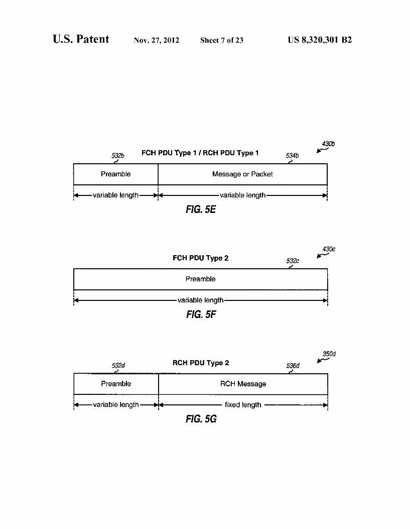
430b
FCHPDU Type 1 IRCHPDU Type 1 534b
-variable length-)H-variable length-> FIG. 5E
430C FCHPDU Type 2 532
KH-variable length -> FIG, 5F
350
Hvariable length-)- fixed length -> FIG 5G
US 8,320,301 B2 U.S. Patent
US 8,320,301 B2 Sheet 11 of 23 Nov. 27, 2012 U.S. Patent
US 8,320,301 B2 Sheet 12 of 23 2012 NOV. 27 U.S. Patent
US 8,320,301 B2 U.S. Patent
US 8,320,301 B2 Sheet 17 Of 23 Nov. 27, 2012 U.S. Patent
þ19/1
i ??un aun?ound/qeeda?i ! – – – – – – – – – – – – – – – –
U.S. Patent Nov. 27, 2012 Sheet 19 Of 23 US 8,320,301 B2
210 1200
POWer Down/Drop
System Acquisition
Power Down/Drop
POWer Down/Drop
Access/
TimeOut/ Release
Connected State Channel
Assignment
FIG, 12A
from Access State 1240
1260 to
Init State Setup TimeOut
SubState to Dornant
State Setup
Complete TimeOut/ Release
to Init State
to In it state
Drop NO FCH or 1280 RCH Activity
Drop
Idle SubState
Open Substate
FCH or RCH Activity
FIG. 12B
US 8,320,301 B2 Sheet 20 of 23 Nov. 27, 2012 U.S. Patent
ndd HOWE
| ?OIS HOVH ?O ?u e?S
US 8,320,301 B2 Sheet 21 of 23 Nov. 27, 2012 U.S. Patent
US 8,320,301 B2 1.
MIMO WLAN SYSTEM
CLAIM OF PRIORITY UNDER 35 U.S.C. S 119
This application claims the benefit of provisional U.S. Application Ser. No. 60/421,309, entitled, “MIMO WLAN System.” filed on Oct. 25, 2002.
BACKGROUND
1. Field The present invention relates generally to data communi
cation, and more specifically to a multiple-input multiple output (MIMO) wireless local area network (WLAN) com munication system.
2. Background Wireless communication systems are widely deployed to
provide various types of communication Such as voice, packet data, and so on. These systems may be multiple-access sys tems capable of Supporting communication with multiple users sequentially or simultaneously by sharing the available system resources. Examples of multiple-access systems include Code Division Multiple Access (CDMA) systems, Time Division Multiple Access (TDMA) systems, and Fre quency Division Multiple Access (FDMA) systems.
Wireless local area networks (WLANs) are also widely deployed to enable communication among wireless elec tronic devices (e.g., computers) via wireless link. A WLAN may employ access points (or base stations) that act like hubs and provide connectivity for the wireless devices. The access points may also connect (or “bridge') the WLAN to wired LANs, thus allowing the wireless devices access to LAN SOUCS.
In a wireless communication system, a radio frequency (RF) modulated signal from a transmitter unit may reach a receiver unit via a number of propagation paths. The charac teristics of the propagation paths typically vary over time due to a number of factors, such as fading and multipath. To provide diversity against deleterious path effects and improve performance, multiple transmit and receive antennas may be used. If the propagation paths between the transmit and receive antennas are linearly independent (i.e., a transmission on one path is not formed as a linear combination of the transmissions on the other paths), which is generally true to at least an extent, then the likelihood of correctly receiving a data transmission increases as the number of antennas increases. Generally, diversity increases and performance improves as the number of transmit and receive antennas increases. A MIMO system employs multiple (N) transmit antennas
and multiple (N) receive antennas for data transmission. A MIMO channel formed by the N transmit and N receive antennas may be decomposed into Ns. Spatial channels, with Nesmin{N, N}. Each of the Ns spatial channels corre sponds to a dimension. The MIMO system can provide improved performance (e.g., increased transmission capacity and/or greater reliability) if the additional dimensionalities created by the multiple transmit and receive antennas are utilized.
The resources for a given communication system are typi cally limited by various regulatory constraints and require ments and by other practical considerations. However, the system may be required to Support a number of terminals, provide various services, achieve certain performance goals, and so on.
5
10
15
25
30
35
40
45
50
55
60
65
2 There is, therefore, a need in the art for a MIMO WLAN
system capable of Supporting multiple users and providing high system performance.
SUMMARY
A multiple-access MIMO WLAN system having various capabilities and able to achieve high performance is described herein. In an embodiment, the system employs MIMO and orthogonal frequency division multiplexing (OFDM) to attain high throughput, combat deleterious path effects, and provide other benefits. Each access point in the system can support multiple user terminals. The allocation of downlink and uplink resources is dependent on the requirements of the user terminals, the channel conditions, and other factors. A channel structure Supporting efficient downlink and
uplink transmissions is also provided herein. The channel structure comprises a number of transport channels that may be used for a number of functions, such as signaling of system parameters and resource assignments, downlink and uplink data transmissions, random access of the system, and so on. Various attributes of these transport channels are config urable, which allows the system to easily adapt to changing channel and loading conditions.
Multiple rates and transmission modes are Supported by the MIMO WLAN system to attain high throughput when Supported by the channel conditions and the capabilities of the user terminals. The rates are configurable based on esti mates of the channel conditions and may be independently selected for the downlink and uplink. Different transmission modes may also be used, depending on the number of anten nas at the user terminals and the channel conditions. Each transmission mode is associated with different spatial pro cessing at the transmitter and receiver and may be selected for use under different operating conditions. The spatial process ing facilitates data transmission from multiple transmit anten nas and/or data reception with multiple receive antennas for higher throughput and/or diversity.
In an embodiment, the MIMO WLAN system uses a single frequency band for both the downlink and uplink, which share the same operating band using time division duplexing (TDD). For a TDD system, the downlink and uplink channel responses are reciprocal. Calibration techniques are provided herein to determine and account for differences in the fre quency responses of the transmit/receive chains at the access point and user terminals. Techniques are also described herein to simplify the spatial processing at the access point and user terminals by taking advantage of the reciprocal nature of the downlink and uplink and the calibration. A pilot structure with several types of pilot used for differ
ent functions is also provided. For example, a beacon pilot may be used for frequency and system acquisition, a MIMO pilot may be used for channel estimation, a steered reference (i.e., a steered pilot) may be used for improved channel esti mation, and a carrier pilot may be used for phase tracking.
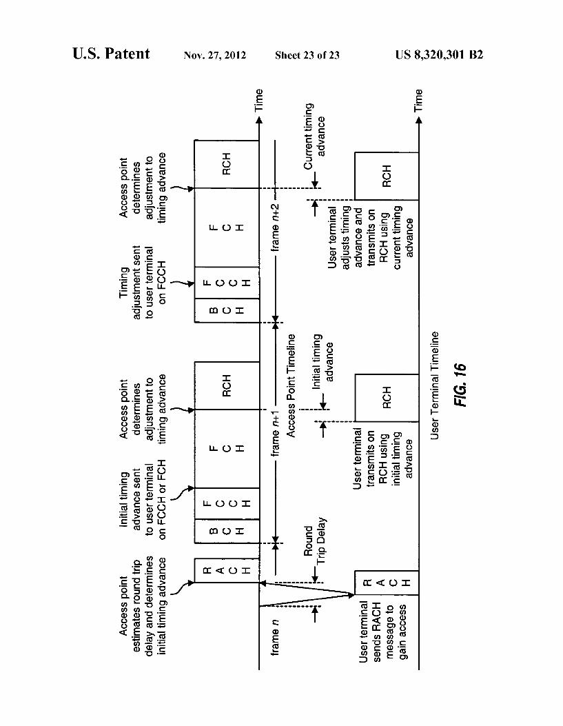
Various control loops for proper system operation are also provided. Rate control may be exercised independently on the downlink and uplink. Power control may be exercised for certain transmissions (e.g., fixed-rate services). Timing con trol may be used for uplink transmissions to account for different propagation delays of user terminals located throughout the system. Random access techniques to allow user terminals to
access the system are also provided. These techniques Sup port system access by multiple user terminals, fast acknowl edgment of system access attempts, and quick assignment of downlink/uplink resources.
US 8,320,301 B2 3
The various aspects and embodiments of the invention are described in further detail below.
BRIEF DESCRIPTION OF THE DRAWINGS
The features and nature of the present invention will become more apparent from the detailed description set forth below when taken in conjunction with the drawings in which like reference characters identify correspondingly through out and wherein:
FIG. 1 shows a MIMO WLAN system; FIG. 2 shows a layer structure for the MIMO WLAN
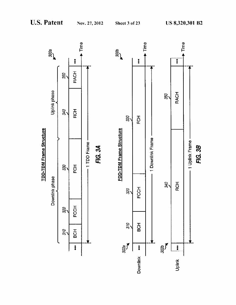
system; FIGS. 3A, 3B and 3C show a TDD-TDM frame structure,
an FDD-TDM frame structure, and an FDD-CDM frame structure, respectively;
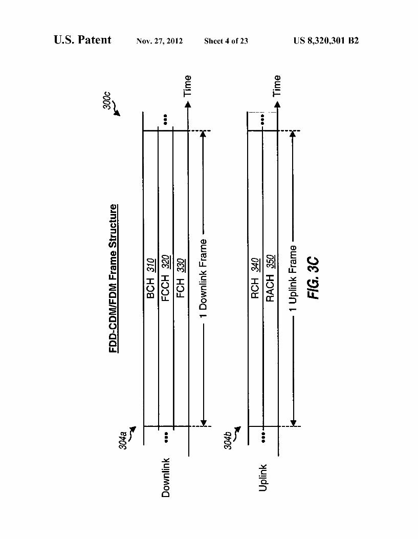
FIG. 4 shows the TDD-TDM frame structure with five transport channels BCH, FCCH, FCH, RCH, and RACH:
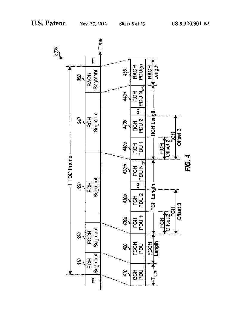
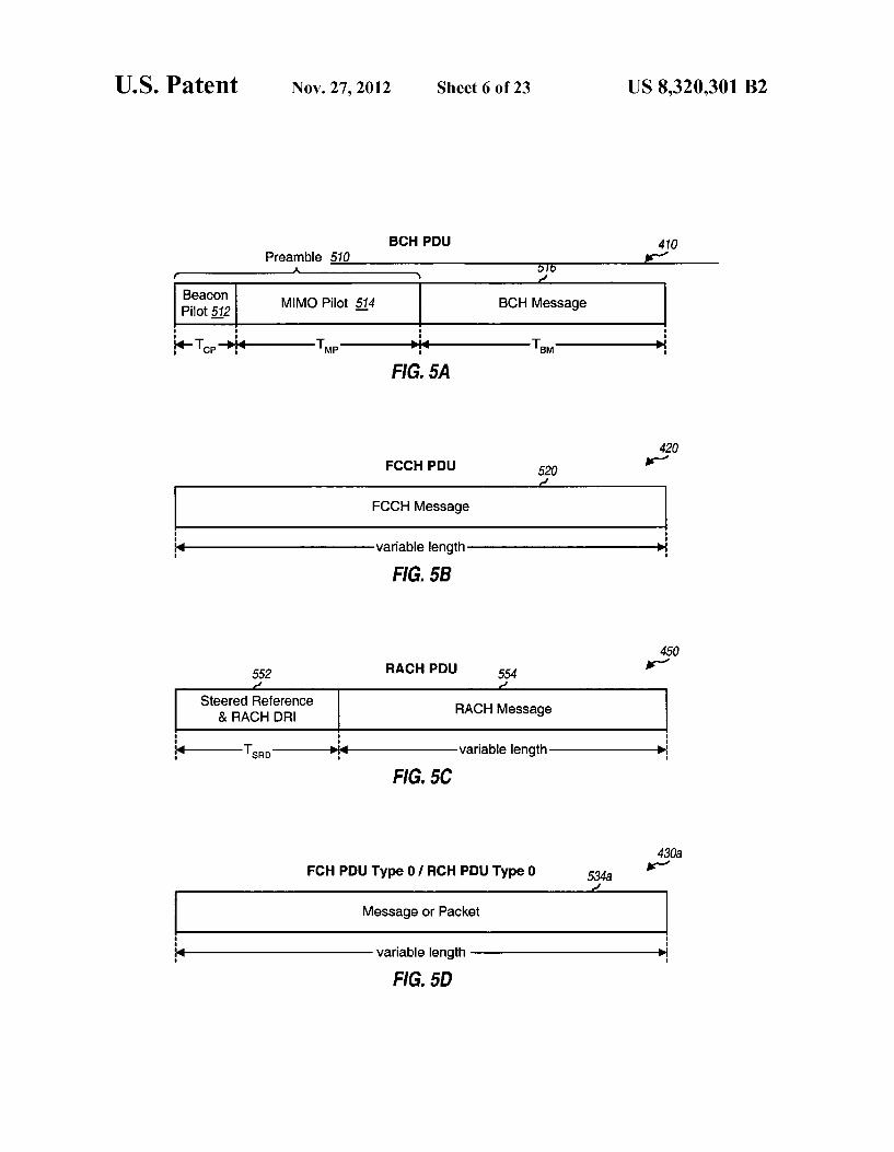
FIGS. 5A through 5G show various protocol data unit (PDU) formats for the five transport channels;
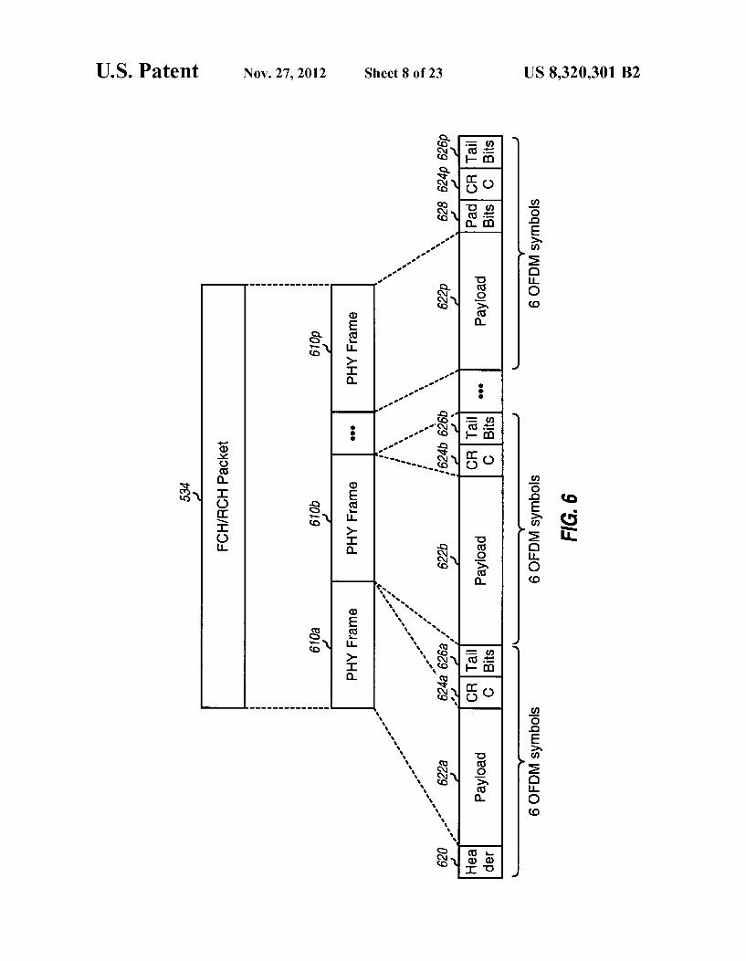
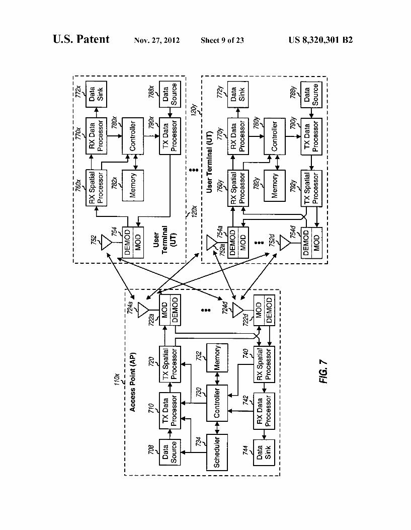
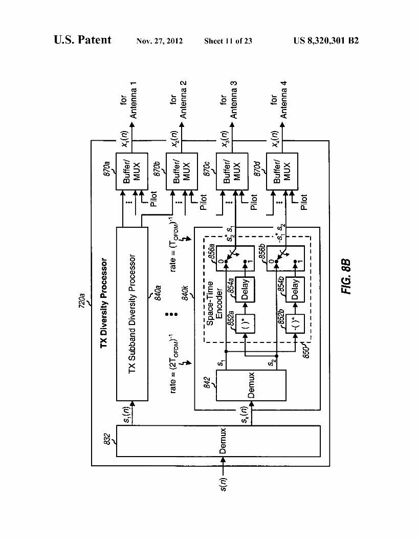
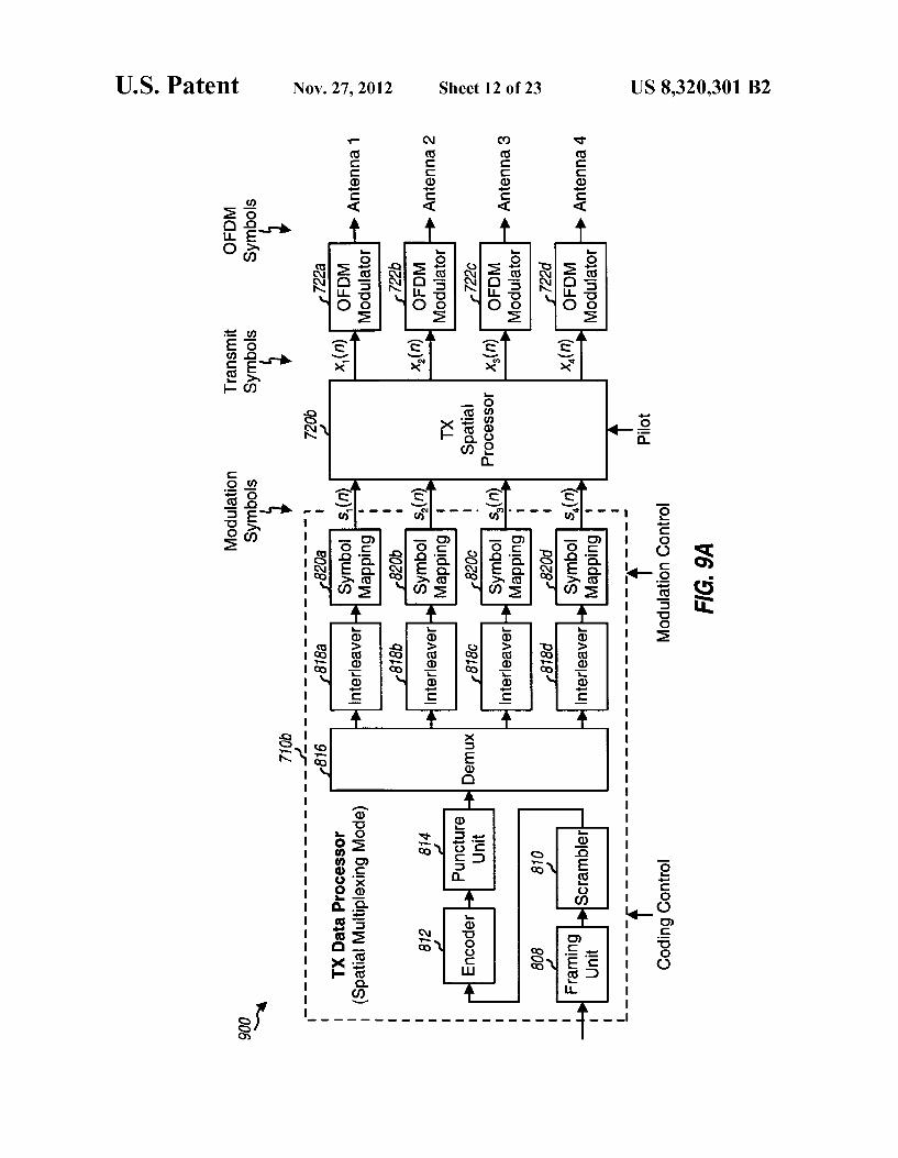
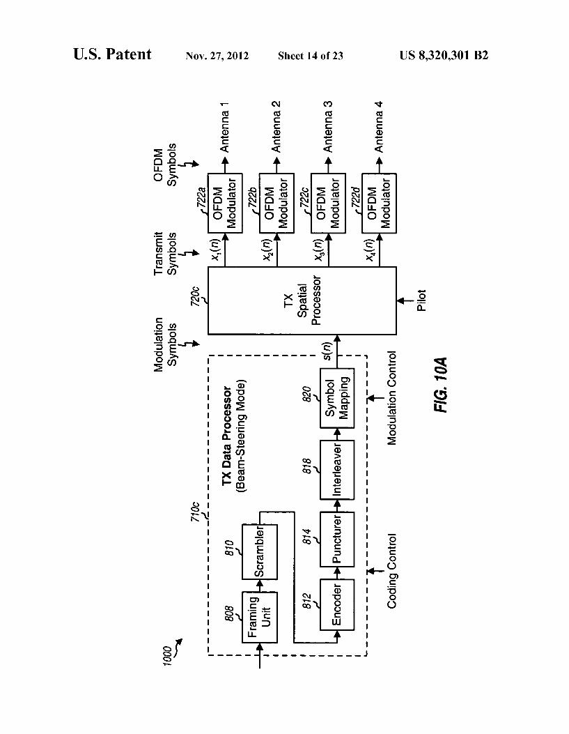
FIG. 6 shows a structure for an FCH/RCH packet; FIG. 7 shows an access point and two user terminals; FIGS. 8A, 9A, and 10A show three transmitter units for the
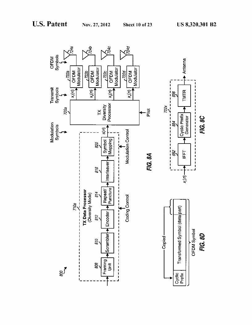
diversity, spatial multiplexing, and beam-steering modes, respectively;
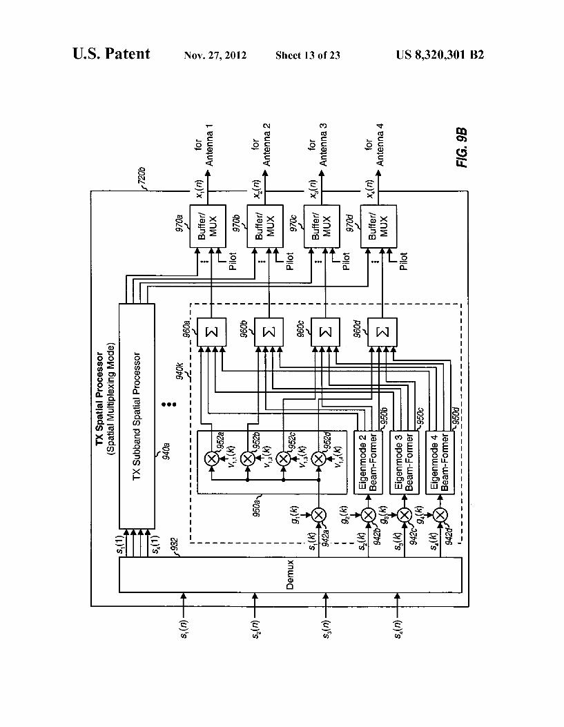
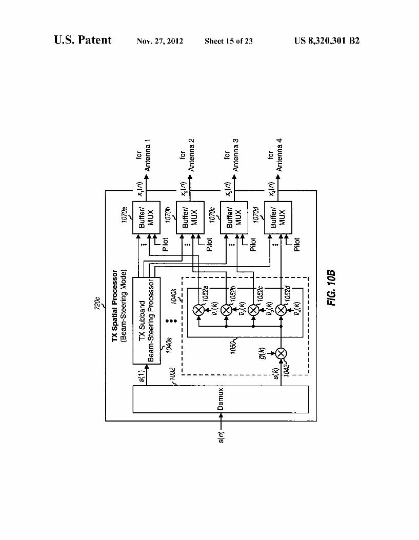
FIGS.8B,9B, and 10B show three TX diversity processors for the diversity, spatial multiplexing, and beam-steering modes, respectively,
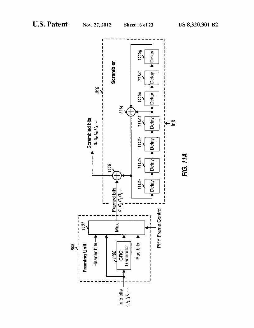
FIG. 8C shows an OFDM modulator; FIG.8D shows an OFDM symbol; FIG. 11A shows a framing unit and a scrambler within a
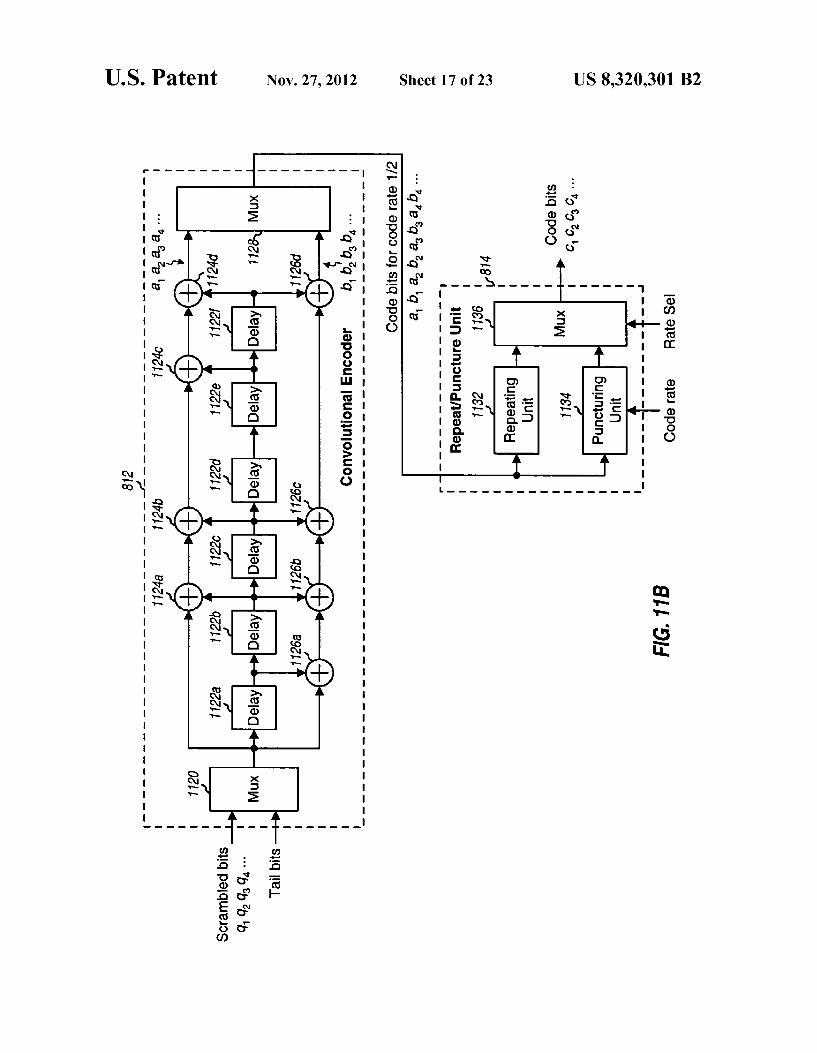
TX data processor; FIG. 11B shows an encoder and a repeat/puncture unit
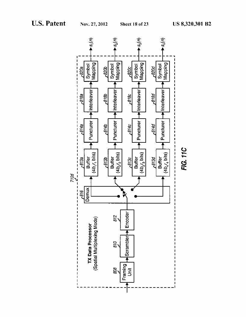
within the TX data processor; FIG. 11C shows another TX data processor that may be
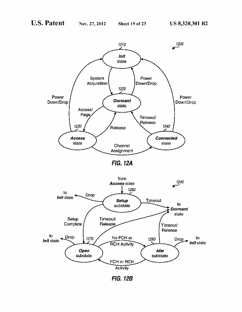
used for the spatial multiplexing mode; FIGS. 12A and 12B show a state diagram for operation of
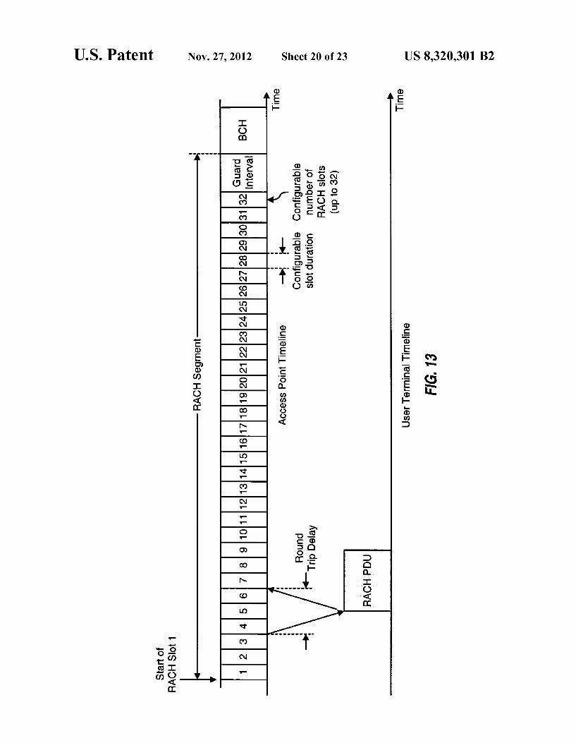
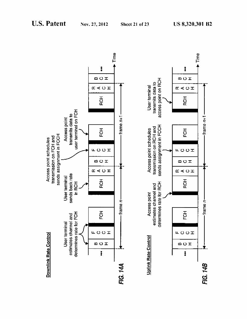
a user terminal; FIG. 13 shows a timeline for the RACH: FIGS. 14A and 14B show processes for controlling the
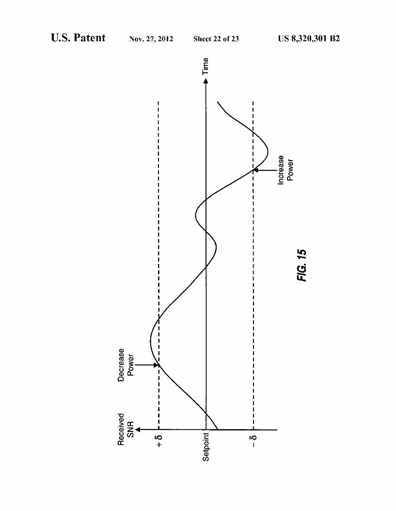
rates of downlink and uplink transmissions, respectively; FIG. 15 shows the operation of a power control loop; and FIG.16 shows a process for adjusting the uplink timing of
a user terminal.
DETAILED DESCRIPTION
The word “exemplary' is used herein to mean “serving as an example, instance, or illustration. Any embodiment or design described herein as "exemplary' is not necessarily to be construed as preferred or advantageous over other embodi ments or designs. I. Overall System
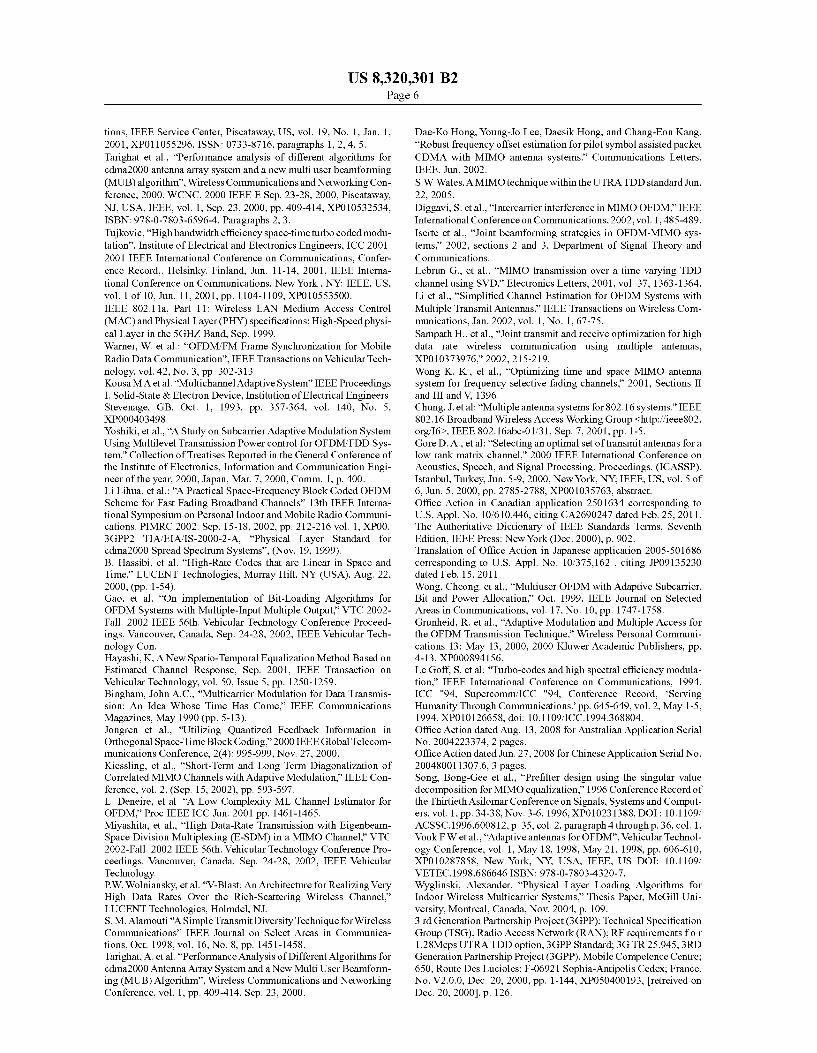
FIG. 1 shows a MIMO WLAN system 100 that supports a number of users and is capable of implementing various aspects and embodiments of the invention. MIMO WLAN system 100 includes a number of access points (APs) 110 that Support communication for a number of user terminals (UTs) 120. For simplicity, only two access points 110 are shown in FIG.1. An access point is generally a fixed Station that is used for communicating with the user terminals. An access point may also be referred to as a base station or some other termi nology.
User terminals 120 may be dispersed throughout the sys tem. Eachuser terminal may be a fixed or mobile terminal that can communicate with the access point. A user terminal may also be referred to as a mobile station, a remote station, an
10
15
25
30
35
40
45
50
55
60
65
4 access terminal, a user equipment (UE), a wireless device, or Some other terminology. Each user terminal may communi cate with one or possibly multiple access points on the down link and/or uplink at any given moment. The downlink (i.e., forward link) refers to transmission from the access point to the user terminal, and the uplink (i.e., reverse link) refers to transmission from the user terminal to the access point.
In FIG. 1, access point 110a communicates with user ter minals 120a through 120f, and access point 110b communi cates with user terminals 120f through 120k. Depending on the specific design of system 100, an access point may com municate with multiple user terminals simultaneously (e.g., via multiple code channels or Subbands) or sequentially (e.g., via multiple time slots). At any given moment, a user terminal may receive downlink transmissions from one or multiple access points. The downlink transmission from each access point may include overhead data intended to be received by multiple user terminals, user-specific data intended to be received by specific user terminals, other types of data, or any combination thereof. The overhead data may include pilot, page and broadcast messages, system parameters, and so on. The MIMO WLAN system is based on a centralized con
troller network architecture. Thus, a system controller 130 couples to access points 110 and may further couple to other systems and networks. For example, system controller 130 may couple to a packet data network (PDN), a wired local area network (LAN), a wide area network (WAN), the Inter net, a public switched telephone network (PSTN), a cellular communication network, and so on. System controller 130 may be designed to perform a number of functions such as (1) coordination and control for the access points coupled to it, (2) routing of data among these access points, (3) access and control of communication with the user terminals served by these access points, and so on. The MIMO WLAN system may be able to provide high
throughput with significantly greater coverage capability than conventional WLAN systems. The MIMO WLAN sys tem can Support synchronous, asynchronous, and isochro nous data/voice services. The MIMO WLAN system may be designed to provide the following features:
High service reliability Guaranteed quality of service (QoS) High instantaneous data rates High spectral efficiency Extended coverage range. The MIMO WLAN system may be operated in various
frequency bands (e.g., the 2.4 GHz and 5.x GHZ U-NII bands), Subject to the bandwidth and emission constraints specific to the selected operating band. The system is designed to Support both indoor and outdoor deployments, with typical maximum cell size of 1 km or less. The system Supports fixed terminal applications, although some operat ing modes also Support portable and limited mobility opera tion.
1. MIMO, MISO, and SIMO In a specific embodiment and as described throughout the
specification, each access point is equipped with four transmit and receive antennas for data transmission and reception, where the same four antennas are used to transmit and to receive. The system also supports the case where the transmit and receive antennas of the device (e.g. access point, user terminal) are not shared, even though this configuration nor mally provides lower performance than when the antennas are shared. The MIMO WLAN system may also be designed Such that each access point is equipped with Some other number of transmit/receive antennas. Each user terminal may be equipped with a single transmit/receive antenna or mul
US 8,320,301 B2 5
tiple transmit/receive antennas for data transmission and reception. The number of antennas employed by each user terminal type may be dependent on various factors such as, for example, the services to be supported by the user terminal (e.g., voice, data, or both), cost considerations, regulatory constraints, safety issues, and so on.
For a given pairing of multi-antenna access point and multi-antenna user terminal, a MIMO channel is formed by the N transmit antennas and N receive antennas available for use for data transmission. Different MIMO channels are formed between the access point and different multi-antenna user terminals. Each MIMO channel may be decomposed into Ns spatial channels, with Nssmin N, N}. Ns data streams may be transmitted on the Ns spatial channels. Spatial pro cessing is required at a receiver and may or may not be performed at a transmitter in order to transmit multiple data streams on the Ns spatial channels. The Ns spatial channels may or may not be orthogonal to
one another. This depends on various factors such as (1) whether or not spatial processing was performed at the trans mitter to obtain orthogonal spatial channels and (2) whether or not the spatial processing at both the transmitter and the receiver was successful in orthogonalizing the spatial chan nels. If no spatial processing is performed at the transmitter, then the Ns spatial channels may be formed with Ns transmit antennas and are unlikely to be orthogonal to one another. The Ns spatial channels may be orthogonalized by per
forming decomposition on a channel response matrix for the MIMO channel, as described below. Each spatial channel is referred to as an eigenmode of the MIMO channel if the Ns spatial channels are orthogonalized using decomposition, which requires spatial processing at both the transmitter and the receiver, as described below. In this case, Ns data streams may be transmitted orthogonally on the Ns eigenmodes. However, an eigenmode normally refers to a theoretical con struct. The Ns spatial channels are typically not completely orthogonal to one another due to various reasons. For example, the spatial channels would not be orthogonal if (1) the transmitter has no knowledge of the MIMO channel or (2) the transmitter and/or receiver have imperfect estimate of the MIMO channel. For simplicity, in the following description, the term "eigenmode” is used to denote the case where an attempt is made to orthogonalize the spatial channels using decomposition, even though the attempt may not be fully Successful due to, for example, an imperfect channel esti mate.
For a given number of (e.g., four) antennas at the access point, the number of spatial channels available for each user terminal is dependent on the number of antennas employed by that user terminal and the characteristics of the wireless MIMO channel that couples the access point antennas and the user terminal antennas. If a user terminal is equipped with one antenna, then the four antennas at the access point and the single antenna at the user terminal form a multiple-input single-output (MISO) channel for the downlink and a single input multiple-output (SIMO) channel for the uplink. The MIMO WLAN system may be designed to support a
number of transmission modes. Table 1 lists the transmission modes supported by an exemplary design of the MIMO WLAN system.
TABLE 1.
Transmission modes Description
SIMO Data is transmitted from a single antenna but may be
10
15
25
30
35
40
45
50
55
60
65
6 TABLE 1-continued
Transmission modes Description
received by multiple antennas for receive diversity. Diversity Data is redundantly transmitted from multiple transmit
antennas and/or multiple Subbands to provide diversity. Data is transmitted on a single (best) spatial channel at at full power using phase steering information for the principal eigenmode of the MIMO channel. Data is transmitted on multiple spatial channels to achieve higher spectral efficiency.
Beam-steering
Spatial multiplexing
For simplicity, the term “diversity' refers to transmit diversity in the following description, unless noted otherwise. The transmission modes available for use for the downlink
and uplink for each user terminal are dependent on the num ber of antennas employed at the user terminal. Table 2 lists the transmission modes available for different terminal types for the downlink and uplink, assuming multiple (e.g., four) antennas at the access point.
TABLE 2
Downlink Uplink
Single- Multi- Single- Multi antenna antenna antenna antenna
Se Se Se Se
Transmission modes terminal terminal terminal terminal
MISO (on downlink), X X X X SIMO (on uplink) Diversity X X X Beam-steering X X X Spatial multiplexing X X
For the downlink, all of the transmission modes except for the spatial multiplexing mode may be used for single-antenna user terminals, and all transmission modes may be used for multi-antenna user terminals. For the uplink, all transmission modes may be used by multi-antenna user terminals, while single-antenna user terminals use the SIMO mode to transmit data from the one available antenna. Receive diversity (i.e., receiving a data transmission with multiple receive antennas) may be used for the SIMO, diversity, and beam-steering modes. The MIMO WLAN system may also be designed to sup
port various other transmission modes, and this is within the Scope of the invention. For example, a beam-forming mode may be used to transmit data on a single eigenmode using both the amplitude and phase information for the eigenmode (instead of only the phase information, which is all that is used by the beam-steering mode). As another example, a “non-steered spatial multiplexing mode can be defined whereby the transmitter simply transmits multiple data streams from multiple transmit antennas (without any spatial processing) and the receiver performs the necessary spatial processing to isolate and recover the data streams sent from the multiple transmit antennas. As yet another example, a “multi-user spatial multiplexing mode can be defined whereby the access point transmits multiple data streams from multiple transmit antennas (with spatial processing) to multiple user terminals concurrently on the downlink. As yet another example, a spatial multiplexing mode can be defined whereby the transmitter performs spatial processing to attempt to orthogonalize the multiple data streams sent on the multiple transmit antennas (but may not be completely suc cessful because of an imperfect channel estimate) and the receiver performs the necessary spatial processing to isolate
US 8,320,301 B2 7
and recover the data streams sent from the multiple transmit antennas. Thus, the spatial processing to transmit multiple data streams via multiple spatial channels may be performed (1) at both the transmitter and receiver, (2) at only the receiver, or (3) at only the transmitter. Different spatial multiplexing modes may be used depending on, for example, the capabili ties of the access point and the user terminals, the available channel state information, System requirements, and so on.
In general, the access points and user terminals may be designed with any number of transmit and receive antennas. For clarity, specific embodiments and designs are described below whereby each access point is equipped with four trans mit/receive antennas, and each user terminal is equipped with four or less transmit/receive antennas.
2. OFDM In an embodiment, the MIMO WLAN system employs
OFDM to effectively partition the overall system bandwidth into a number of (N) orthogonal subbands. These subbands are also referred to astones, bins, or frequency channels. With OFDM, each subband is associated with a respective subcar rier that may be modulated with data. For a MIMO system that utilizes OFDM, each spatial channel of each subband may be viewed as an independent transmission channel where the complex gain associated with each Subband is effectively constant across the subband bandwidth.
In an embodiment, the system bandwidth is partitioned into 64 orthogonal Subbands (i.e., N-64), which are assigned indices of -32 to +31. Of these 64 Subbands, 48 Subbands (e.g., with indices of t1,..., 6, 8, ..., 20, 22, ..., 26}) are used for data, 4 subbands (e.g., with indices oft{7, 21}) are used for pilot and possibly signaling, the DC subband (with index of 0) is not used, and the remaining Subbands are also not used and serve as guard subbands. This OFDM subband structure is described in further detail in a document for IEEE Standard 802.11a and entitled “Part 11: Wireless LAN Medium Access Control (MAC) and Physical Layer (PHY) Specifications: High-speed Physical Layer in the 5 GHZ Band.” September 1999, which is publicly available and incorporated herein by reference. Different numbers of sub bands and various other OFDM subband structures may also be implemented for the MIMO WLAN system, and this is within the scope of the invention. For example, all 53 sub bands with indices from -26 to +26 may be used for data transmission. As another example, a 128-Subband structure, a 256-subband structure, or a Subband structure with some other number of Subbands may be used. For clarity, the MIMO WLAN system is described below with the 64-sub band structure described above.
For OFDM, the data to be transmitted on each subband is first modulated (i.e., symbol mapped) using a particular modulation scheme selected for use for that Subband. Zeros are provided for the unused subbands. For each symbol period, the modulation symbols and Zeros for all N subbands are transformed to the time domain using an inverse fast Fourier transform (IFFT) to obtain a transformed symbol that contains N time-domain samples. The duration of each transformed symbol is inversely related to the bandwidth of each subband. In one specific design for the MIMO WLAN system, the system bandwidth is 20 MHz, N=64, the band width of each Subband is 312.5 KHZ, and the duration of each transformed symbol is 3.2 usec. OFDM can provide certain advantages, such as the ability
to combat frequency selective fading, which is characterized by different channel gains at different frequencies of the overall system bandwidth. It is well known that frequency selective fading causes inter-symbol interference (ISI), which is a phenomenon whereby each symbol in a received signal
10
15
25
30
35
40
45
50
55
60
65
8 acts as distortion to Subsequent symbols in the received sig nal. The ISI distortion degrades performance by impacting the ability to correctly detect the received symbols. Fre quency selective fading can be conveniently combated with OFDM by repeating a portion of (or appending a cyclic prefix to) each transformed symbol to form a corresponding OFDM symbol, which is then transmitted. The length of the cyclic prefix (i.e., the amount to repeat)
for each OFDM symbol is dependent on the delay spread of the wireless channel. In particular, to effectively combat ISI, the cyclic prefix should belonger than the maximum expected delay spread for the system.
In an embodiment, cyclic prefixes of different lengths may be used for the OFDM symbols, depending on the expected delay spread. For the specific MIMO WLAN system described above, a cyclic prefix of 400 nsec (8 samples) or 800 nsec (16 samples) may be selected for use for the OFDM symbols. A “short OFDM symbol uses the 400 nsec cyclic prefix and has a duration of 3.6 usec. A “long OFDM symbol uses the 800 nsec cyclic prefix and has a duration of 4.0 usec. Short OFDM symbols may be used if the maximum expected delay spread is 400 nsec or less, and long OFDM symbols may be used if the delay spread is greater than 400 nsec. Different cyclic prefixes may be selected for use for different transport channels, and the cyclic prefix may also be dynami cally selectable, as described below. Higher system through put may be achieved by using the shorter cyclic prefix when possible, since more OFDM symbols of shorter duration can be transmitted over a given fixed time interval. The MIMO WLAN system may also be designed to not
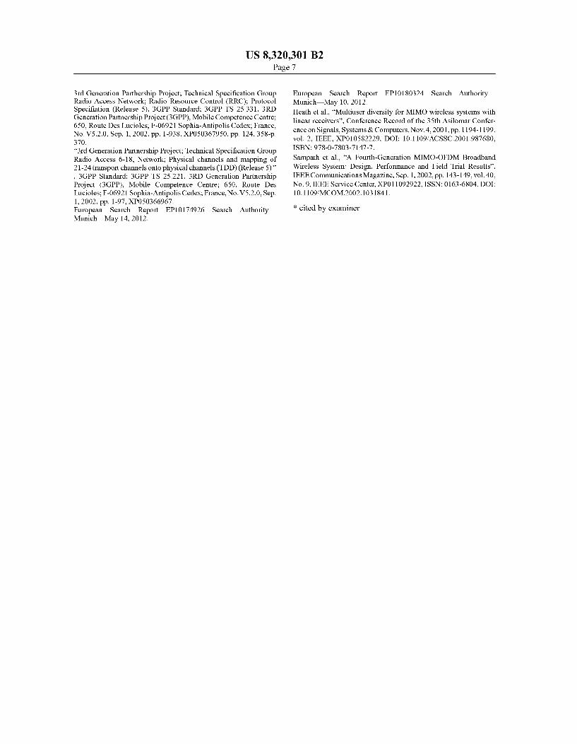
utilize OFDM, and this is within the scope of the invention. 3. Layer Structure FIG. 2 illustrates a layer structure 200 that may be used for
the MIMO WLAN system. Layer structure 200 includes (1) applications and upper layer protocols that approximately correspond to Layer 3 and higher of the ISO/OSI reference model (upper layers), (2) protocols and services that corre spond to Layer 2 (the link layer), and (3) protocols and Ser vices that correspond to Layer 1 (the physical layer). The upper layers includes various applications and proto
cols, such as signaling services 212, data services 214, Voice services 216, circuit data applications, and so on. Signaling is typically provided as messages and data is typically provided as packets. The services and applications in the upper layers originate and terminate messages and packets according to the semantics and timing of the communication protocol between the access point and the user terminal. The upper layers utilize the services provided by Layer 2.
Layer 2 supports the delivery of messages and packets generated by the upper layers. In the embodiment shown in FIG. 2. Layer 2 includes a Link Access Control (LAC) sub layer 220 and a Medium Access Control (MAC) sublayer 230. The LAC sublayer implements a data link protocol that pro vides for the correct transport and delivery of messages gen erated by the upper layers. The LAC sublayer utilizes the services provided by the MAC sublayer and Layer 1. The MAC Sublayer is responsible for transporting messages and packets using the services provided by Layer 1. The MAC Sublayer controls the access to Layer 1 resources by the applications and services in the upper layers. The MAC sub layer may include a Radio Link Protocol (RLP) 232, which is a retransmission mechanism that may be used to provide higher reliability for packet data. Layer 2 provides protocol data units (PDUs) to Layer 1.
Layer 1 comprises physical layer 240 and Supports the transmission and reception of radio signals between the access point and user terminal. The physical layer performs
US 8,320,301 B2
coding, interleaving, modulation, and spatial processing for various transport channels used to send messages and packets generated by the upper layers. In this embodiment, the physi cal layer includes a multiplexing Sublayer 242 that multi plexes processed PDUs for various transport channels into the proper frame format. Layer 1 provides data in units of frames.
FIG. 2 shows a specific embodiment of a layer structure that may be used for the MIMO WLAN system. Various other Suitable layer structures may also be designed and used for the MIMO WLAN system, and this is within the scope of the invention. The functions performed by each layer are described in further detail below where appropriate.
4. Transport Channels A number of services and applications may be supported
by the MIMO WLAN system. Moreover, other data required for proper system operation may need to be sent by the access point or exchanged between the access point and user termi nals. A number of transport channels may be defined for the MIMO WLAN system to carry various types of data. Table 3 lists an exemplary set of transport channels and also provides a brief description for each transport channel.
TABLE 3
Transport channels Description
Broadcast channel BCH parameters to the user terminals.
Forward control FCCH channel
RACH. Forward channel FCH
broadcast messages to multiple user terminals. Random access RACH channel Reverse channel
and send short messages to the access point. RCH
May also carry a reference used by the access point for channel estimation.
As shown in Table 3, the downlink transport channels used by the access point include the BCH, FCCH, and FCH. The uplink transport channels used by the user terminals include the RACH and RCH. Each of these transport channels is described in further detail below. The transport channels listed in Table 3 represent a specific
embodiment of a channel structure that may be used for the MIMO WLAN system. Fewer, additional, and/or different transport channels may also be defined for use for the MIMO WLAN system. For example, certain functions may be sup ported by function-specific transport channels (e.g., pilot, paging, power control, and sync channel channels). Thus, other channel structures with different sets of transport chan nels may be defined and used for the MIMO WLAN system, and this is within the scope of the invention.
5. Frame Structures A number of frame structures may be defined for the trans
port channels. The specific frame structure to use for the MIMO WLAN system is dependent on various factors such as, for example, (1) whether the same or different frequency bands are used for the downlink and uplink and (2) the mul tiplexing scheme used to multiplex the transport channels together.
If only one frequency band is available, then the downlink and uplink may be transmitted on different phases of a frame using time division duplexing (TDD), as described below. If
10
15
Used by the access point to transmit pilot and system
Used by the access point to allocate resources on the downlink and uplink. The resource allocation may be performed on a frame-by-frame basis. Also used to provide acknowledgment for messages received on the
45
50
55
60
65
10 two frequency bands are available, then the downlink and uplink may be transmitted on different frequency bands using frequency division duplexing (FDD).
For both TDD and FDD, the transport channels may be multiplexed together using time division multiplexing (TDM), code division multiplexing (CDM), frequency divi sion multiplexing(FDM), and so on. For TDM, each transport channel is assigned to a different portion of a frame. For CDM, the transport channels are transmitted concurrently but each transport channel is channelized by a different channel ization code, similar to that performed in a code division multiple access (CDMA) system. For FDM, each transport channel is assigned a different portion of the frequency band for the link.
Table 4 lists the various frame structures that may be used to carry the transport channels. Each of these frame structures is described in further detail below. For clarity, the frame structures are described for the set of transport channels listed in Table 3.
Used by the access point to transmit user-specific data o the user terminals and possibly a reference (pilot) used by the user terminals for channel estimation. May also be used in a broadcast mode to send page and
Used by the user terminals to gain access to the system
Used by the user terminals to transmit data to the access point.
TABLE 4
Shared frequency band for downlink and uplink
Separate frequency bands for downlink and uplink
TDD-TDM frame structure TDD-CDM frame structure
FDD-TDM frame structure FDD-CDM frame structure
Time division Code division
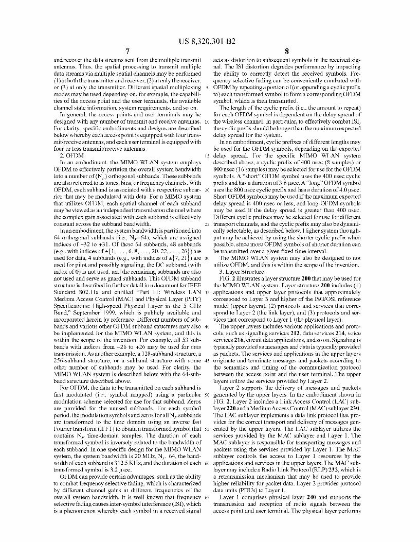
FIG. 3A illustrates an embodiment of a TDD-TDM frame structure 300a that may be used if a single frequency band is used for both the downlink and uplink. Data transmission occurs in units of TDD frames. Each TDD frame may be defined to span aparticular time duration. The frame duration may be selected based on various factors such as, for example, (1) the bandwidth of the operating band, (2) the expected sizes of the PDUs for the transport channels, and so on. In general, a shorter frame duration may provide reduced delays. How ever, a longer frame duration may be more efficient since header and overhead may represent a smaller fraction of the frame. In a specific embodiment, each TDD frame has a duration of 2 m.sec.
Each TDD frame is partitioned into a downlink phase and an uplink phase. The downlink phase is further partitioned into three segments for the three downlink transport chan nels the BCH, FCCH, and FCH. The uplink phase is further partitioned into two segments for the two uplink transport channels—the RCH and RACH.
US 8,320,301 B2 11
The segment for each transport channel may be defined to have either a fixed duration or a variable duration that can change from frame to frame. In an embodiment, the BCH segment is defined to have a fixed duration, and the FCCH, FCH, RCH, and RACH segments are defined to have variable durations. The segment for each transport channel may be used to
carry one or more protocol data units (PDUs) for that trans port channel. In the specific embodiment shown in FIG. 3A, a BCH PDU is transmitted in a first segment 310, an FCCH PDU is transmitted in a second segment 320, and one or more FCH PDUs are transmitted in a third segment 330 of the downlink phase. On the uplink phase, one or more RCH PDUs are transmitted in a fourth segment 340 and one or more RACH PDUs are transmitted in a fifth segment 350 of the TDD frame.
Frame structure 300a represents a specific arrangement of the various transport channels within a TDD frame. This arrangement can provide certain benefits such as reduced delays for data transmission on the downlink and uplink. The BCH is transmitted first in the TDD frame since it carries system parameters that may be used for the PDUs of the other transport channels within the same TDD frame. The FCCH is transmitted next since it carries channel assignment informa tion indicative of which user terminal(s) are designated to receive downlink data on the FCH and which user terminal(s) are designated to transmit uplink data on the RCH within the current TDD frame. Other TDD-TDM frame structures may also be defined and used for the MIMO WLAN system, and this is within the scope of the invention.
FIG. 3B illustrates an embodiment of an FDD-TDM frame structure 300b that may be used if the downlinkanduplink are transmitted using two separate frequency bands. Downlink data is transmitted in a downlink frame 302a, and uplink data is transmitted in an uplink frame 302b. Each downlink and uplink frame may be defined to span aparticular time duration (e.g., 2 m sec). For simplicity, the downlink and uplink frames may be defined to have the same duration and may further be defined to be aligned at the frame boundaries. However, dif ferent frame durations and/or non-aligned (i.e., offset) frame boundaries may also be used for the downlink and uplink. As shown in FIG. 3B, the downlink frame is partitioned
into three segments for the three downlink transport channels. The uplink frame is partitioned into two segments for the two uplink transport channels. The segment for each transport channel may be defined to have a fixed or variable duration, and may be used to carry one or more PDUs for that transport channel.
In the specific embodiment shown in FIG. 3B, the down link frame carries a BCH PDU, an FCCH PDU, and one or more FCHPDUs in segments 310,320, and 330, respectively. The uplink frame carries one or more RCHPDUs and one or more RACH PDUs in segments 340 and 350, respectively. This specific arrangement may provide the benefits described above (e.g., reduced delays for data transmission). The trans port channels may have different PDU formats, as described below. Other FDD-TDM frame structures may also be defined and used for the MIMO WLAN system, and this is within the scope of the invention.
FIG. 3C illustrates an embodiment of an FDD-CDMAFDM frame structure 300c that may also be used if the downlink and uplink are transmitted using separate frequency bands. Downlink data may be transmitted in a downlink frame 304a, and uplink data may be transmitted in an uplink frame 304b. The downlink and uplink frames may be defined to have the same duration (e.g., 2 mSec) and aligned at the frame bound a1S.
5
10
15
25
30
35
40
45
50
55
60
65
12 As shown in FIG. 3C, the three downlink transport chan
nels are transmitted concurrently in the downlink frame, and the two uplink transport channels are transmitted concur rently in the uplink frame. For CDM, the transport channels for each link are “channelized with different channelization codes, which may be Walsh codes, orthogonal variable spreading factor (OVSF) codes, quasi-orthogonal functions (QOF), and so on. For FDM, the transport channels for each link are assigned different portions of the frequency band for the link. Different amounts of transmit power may also be used for different transport channels in each link.
Other frame structures may also be defined for the down link and uplink transport channels, and this is within the scope of the invention. Moreover, it is possible to use different types of frame structure for the downlink and uplink. For example, a TDM-based frame structure may be used for the downlink and a CDM-based frame structure may be used for the uplink.
In the following description, the MIMO WLAN system is assumed to use one frequency band for both downlink and uplink transmissions. For clarity, the TDD-TDM frame struc ture shown in FIG.3A is used for the MIMO WLAN system. For clarity, a specific implementation of the TDD-TDM frame structure is described throughout the specification. For this implementation, the duration of each TDD frame is fixed at 2 msec, and the number of OFDM symbols per TDD frame is a function of the length of the cyclic prefix used for the OFDM symbols. The BCH has a fixed duration of 80 usec and uses the 800 nsec cyclic prefix for the OFDM symbols trans mitted. The remainder of the TDD frame contains 480 OFDM symbols if the 800 nsec cyclic prefix is used, and 533 OFDM symbols plus 1.2 usec of excess time if the 400 nsec cyclic prefix is used. The excess time can be added to the guard interval at the end of the RACH segment. Other frame struc tures and other implementations may also be used, and this is within the scope of the invention. II. Transport Channels The transport channels are used to send various types of
data and may be categorized into two groups: common trans port channels and dedicated transport channels. Because the common and dedicated transport channels are used for dif ferent purposes, different processing may be used for these two groups of transport channels, as described in further detail below. Common Transport Channels. The common transport
channels include the BCH, FCCH, and RACH. These trans port channels are used to send data to or receive data from multiple user terminals. For improved reliability, the BCH and FCCH are transmitted by the access point using the diversity mode. On the uplink, the RACH is transmitted by the user terminals using the beam-steering mode (if supported by the user terminal). The BCH is operated at a known fixed rate so that the user terminals can receive and process the BCH without any additional information. The FCCH and RACH support multiple rates to allow for greater efficiency. As used herein, each “rate' or “rate set is associated with a particular code rate (or coding scheme) and a particular modulation scheme.
Dedicated Transport Channels. The dedicated transport channels include the FCH and RCH. These transport channels are normally used to send user-specific data to or by specific user terminals. The FCH and RCH may be dynamically allo cated to the user terminals as necessary and as available. The FCH may also be used in a broadcast mode to send overhead, page, and broadcast messages to the user terminals. In gen eral, the overhead, page, and broadcast messages are trans mitted prior to any user-specific data on the FCH.
US 8,320,301 B2 13
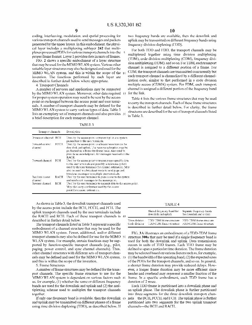
FIG. 4 illustrates an exemplary transmission on the BCH, FCCH, FCH, RCH, and RACH based on TDD-TDM frame structure 300a. In this embodiment, one BCH PDU 410 and one FCCHPDU 420 are transmitted in BCH segment 310 and FCCH segment 320, respectively. FCH segment 330 may be used to send one or more FCH PDUs 430, each of which may be intended for a specific user terminal or multiple user ter minals. Similarly, one or more RCH PDUs 440 may be sent by one or more user terminals in RCH segment 340. The start of each FCH/RCH PDU is indicated by an FCH/RCH offset from the end of the preceding segment. A number of RACH PDUs 450 may be sent in RACH segment 350 by a number of user terminals to access the system and/or to send short mes sages, as described below.
For clarity, the transport channels are described for the specific TDD-TDM frame structure shown in FIGS. 3A and 4.
1. Broadcast Channel (BCH)—Downlink The BCH is used by the access point to transmit a beacon
pilot, a MIMO pilot, and system parameters to the user ter minals. The beacon pilot is used by the user terminals to acquire system timing and frequency. The MIMO pilot is used by the user terminals to estimate the MIMO channel formed by the access point antennas and their own antennas. The beacon and MIMO pilots are described in further detail below. The system parameters specify various attributes of the downlink and uplink transmissions. For example, since the durations of the FCCH, FCH, RACH, and RCH segments are variable, the system parameters that specify the length of each of these segments for the current TDD frame are sent in the BCH.
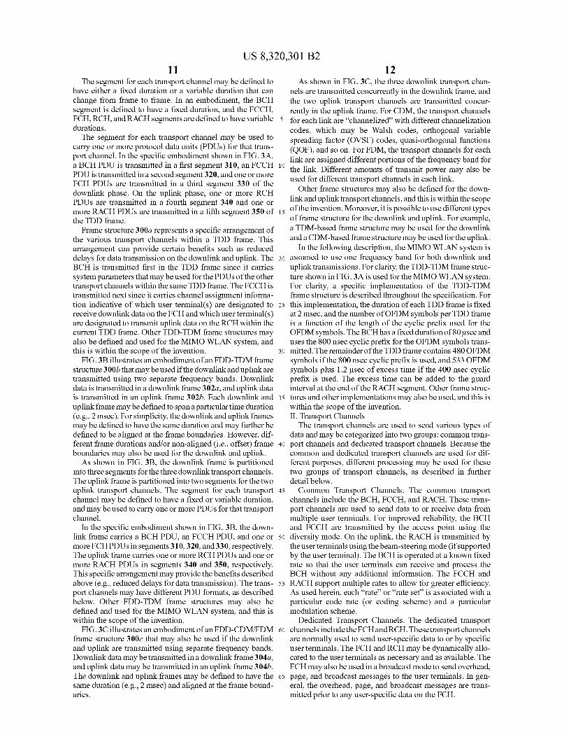
FIG. 5A illustrates an embodiment of BCH PDU 410. In this embodiment, BCHPDU410 includes a preamble portion 510 and a message portion 516. Preamble portion 510 further includes a beacon pilot portion 512 and a MIMO pilot portion 514. Portion 512 carries a beacon pilot and has a fixed dura tion of T-8 usec. Portion 514 carries a MIMO pilot and has a fixed duration of T-3 usec. Portion 516 carries a BCH message and has a fixed duration of T-40 usec. The dura tion of the BCH PDU is fixed at T+T+T 80 usec. A preamble may be used to send one or more types of pilot
and/or other information. A beacon pilot comprises a specific set of modulation symbols that is transmitted from all trans mit antennas. A MIMO pilot comprises a specific set of modulation symbols that is transmitted from all transmit antennas with different orthogonal codes, which then allows the receivers to recover the pilot transmitted from each antenna. Different sets of modulation symbols may be used for the beacon and MIMO pilots. The generation of the bea con and MIMO pilots is described in further detail below. The BCH message carries system configuration informa
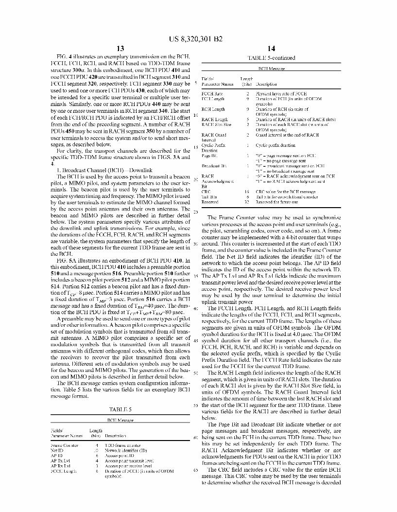
tion. Table 5 lists the various fields for an exemplary BCH message format.
TABLE 5
BCH Message
Fields. ParameterNames
Length (bits) Description
Frame Counter 4 TDD frame counter Net ID 10 Network identifier (ID) APID 6 Access point ID APTx Lvl 4. Access point transmit level APRX Lvl 3. Access point receive level FCCH Length 6 Duration of FCCH (in units of OFDM
symbols)
10
15
25
30
40
45
50
55
60
65
14 TABLE 5-continued
BCH Message
Fields. Length Parameter Names (bits) Description
FCCHRate 2 Physical layer rate of FCCH FCH Length 9 Duration of FCH (in units of OFDM
symbols) RCH Length 9 Duration of RCH (in units of
OFDM symbols) RACH Length 5. Duration of RACH (in units of RACH slots) RACHSlot Size 2 Duration of each RACH slot (in units of
OFDM symbols) RACH Guard 2 Guard interval at the end of RACH interval Cyclic Prefix 1 Cyclic prefix duration Duration Page Bit 1 “0” = page message sent on FCH
1 = no page message sent Broadcast Bit 1 “0” = broadcast message sent on FCH
1 = no broadcast message sent RACEH 1 O = RACH acknowledgment sent on FCH Acknowledgment 1 = no RACH acknowledgment sent Bit CRC 16 CRC value for the BCH message Tail Bits 6 Tail bits for convolutional encoder Reserved 32 Reserved for future use
The Frame Counter value may be used to synchronize various processes at the access point and user terminals (e.g., the pilot, Scrambling codes, cover code, and so on). A frame counter may be implemented with a 4-bit counter that wraps around. This counter is incremented at the start of each TDD frame, and the counter value is included in the Frame Counter field. The Net ID field indicates the identifier (ID) of the network to which the access point belongs. The AP ID field indicates the ID of the access point within the network ID. The APTX LV1 and AP RX Lvl fields indicate the maximum transmit power leveland the desired receive power level at the access point, respectively. The desired receive power level may be used by the user terminal to determine the initial uplink transmit power. The FCCH Length, FCH Length, and RCH Length fields
indicate the lengths of the FCCH, FCH, and RCH segments, respectively, for the current TDD frame. The lengths of these segments are given in units of OFDM symbols. The OFDM symbol duration for the BCH is fixed at 4.0 usec. The OFDM symbol duration for all other transport channels (i.e., the FCCH, FCH, RACH, and RCH) is variable and depends on the selected cyclic prefix, which is specified by the Cyclic Prefix Duration field. The FCCH Rate field indicates the rate used for the FCCH for the current TDD frame. The RACH Length field indicates the length of the RACH
segment, which is given in units of RACH slots. The duration of each RACH slot is given by the RACH Slot Size field, in units of OFDM symbols. The RACH Guard Interval field indicates the amount of time between the last RACH slot and the start of the BCH segment for the next TDD frame. These various fields for the RACH are described in further detail below. The Page Bit and Broadcast Bit indicate whether or not
page messages and broadcast messages, respectively, are being sent on the FCH in the current TDD frame. These two bits may be set independently for each TDD frame. The RACH Acknowledgment Bit indicates whether or not acknowledgments for PDUs sent on the RACH in prior TDD frames are being sent on the FCCH in the current TDD frame. The CRC field includes a CRC value for the entire BCH
message. This CRC value may be used by the user terminals to determine whether the received BCH message is decoded
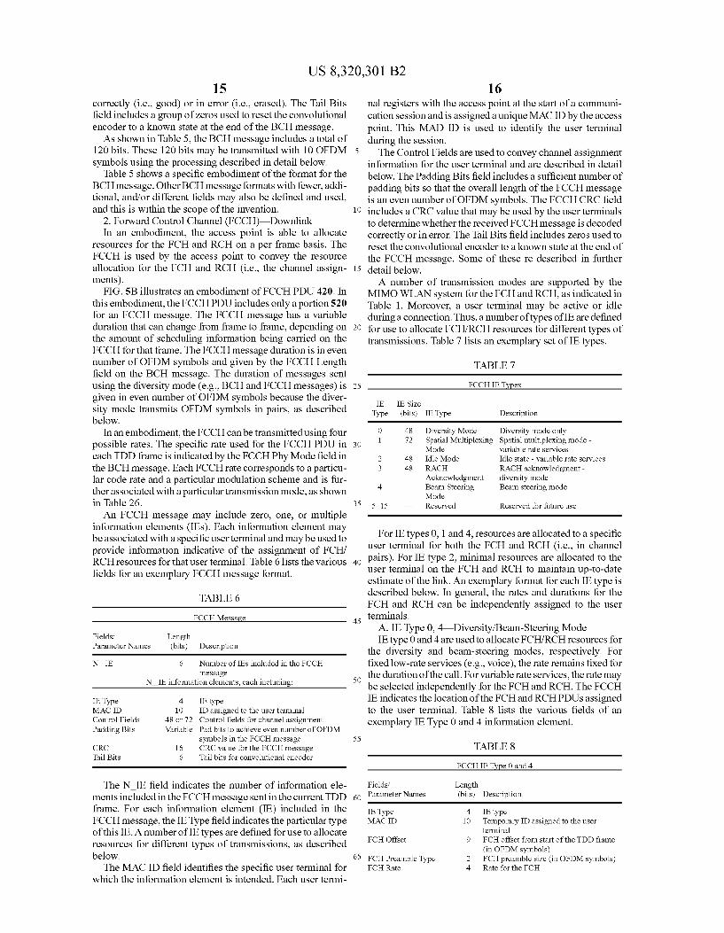
US 8,320,301 B2 15
correctly (i.e., good) or in error (i.e., erased). The Tail Bits field includes a group of Zeros used to reset the convolutional encoder to a known state at the end of the BCH message. As shown in Table 5, the BCH message includes a total of
120 bits. These 120 bits may be transmitted with 10 OFDM symbols using the processing described in detail below.
Table 5 shows a specific embodiment of the format for the BCH message. Other BCH message formats with fewer, addi tional, and/or different fields may also be defined and used, and this is within the scope of the invention.
2. Forward Control Channel (FCCH)–Downlink In an embodiment, the access point is able to allocate
resources for the FCH and RCH on a per frame basis. The FCCH is used by the access point to convey the resource allocation for the FCH and RCH (i.e., the channel assign ments). FIG.SB illustrates an embodiment of FCCH PDU 420. In
this embodiment, the FCCH PDU includes only a portion 520 for an FCCH message. The FCCH message has a variable duration that can change from frame to frame, depending on the amount of Scheduling information being carried on the FCCH for that frame. The FCCH message duration is in even number of OFDM symbols and given by the FCCH Length field on the BCH message. The duration of messages sent using the diversity mode (e.g., BCH and FCCH messages) is given in even number of OFDM symbols because the diver sity mode transmits OFDM symbols in pairs, as described below.
In an embodiment, the FCCH can be transmitted using four possible rates. The specific rate used for the FCCH PDU in each TDD frame is indicated by the FCCH Phy Mode field in the BCH message. Each FCCH rate corresponds to a particu lar code rate and a particular modulation scheme and is fur ther associated with a particular transmission mode, as shown in Table 26. An FCCH message may include Zero, one, or multiple
information elements (IES). Each information element may be associated with a specific user terminal and may be used to provide information indicative of the assignment of FCH/ RCH resources for that user terminal. Table 6 lists the various fields for an exemplary FCCH message format.
TABLE 6
FCCH Message
Fields. Length ParameterNames (bits) Description
N IE 6 Number of IES included in the FCCH message
N IE information elements, each including:
IEType 4 IE type MAC ID 10 ID assigned to the user terminal Control Fields 48 or 72 Control fields for channel assignment Padding Bits Variable Pad bits to achieve even number of OFDM
symbols in the FCCH message CRC 16 CRC value for the FCCH message Tail Bits 6 Tail bits for convolutional encoder
The NIE field indicates the number of information ele ments included in the FCCH message sent in the current TDD frame. For each information element (IE) included in the FCCH message, the IEType field indicates the particular type of this IE. A number of IE types are defined for use to allocate resources for different types of transmissions, as described below.
The MAC ID field identifies the specific user terminal for which the information element is intended. Each user termi
5
10
15
25
30
35
40
45
50
55
60
65
16 nal registers with the access point at the start of a communi cation session and is assigned a unique MAC ID by the access point. This MAD ID is used to identify the user terminal during the session. The Control Fields are used to convey channel assignment
information for the user terminal and are described in detail below. The Padding Bits field includes a sufficient number of padding bits so that the overall length of the FCCH message is an even number of OFDM symbols. The FCCHCRC field includes a CRC value that may be used by the user terminals to determine whether the received FCCH message is decoded correctly or in error. The Tail Bits field includes Zeros used to reset the convolutional encoder to a known state at the end of the FCCH message. Some of these re described in further detail below. A number of transmission modes are Supported by the
MIMO WLAN system for the FCH and RCH, as indicated in Table 1. Moreover, a user terminal may be active or idle during a connection. Thus, a number of types of IE are defined for use to allocate FCH/RCH resources for different types of transmissions. Table 7 lists an exemplary set of IE types.
TABLE 7
FCCHIETypes
IE IE Size Type (bits) IEType Description
O 48 Diversity Mode Diversity mode only 1 72 Spatial Multiplexing Spatial multiplexing mode -
Mode variable rate services 2 48 Idle Mode Idle state - variable rate services 3 48 RACH RACH acknowledgment
Acknowledgment diversity mode 4 Beam Steering Beam steering mode
Mode 5-15 — Reserved Reserved for future use
For IE types 0,1 and 4, resources are allocated to a specific user terminal for both the FCH and RCH (i.e., in channel pairs). For IE type 2, minimal resources are allocated to the user terminal on the FCH and RCH to maintain up-to-date estimate of the link. An exemplary format for each IE type is described below. In general, the rates and durations for the FCH and RCH can be independently assigned to the user terminals.
A. IE Type 0, 4 Diversity/Beam-Steering Mode IE type 0 and 4 are used to allocate FCH/RCH resources for
the diversity and beam-steering modes, respectively. For fixed low-rate services (e.g., voice), the rate remains fixed for the duration of the call. For variable rate services, the rate may be selected independently for the FCH and RCH. The FCCH IE indicates the location of the FCH and RCHPDUs assigned to the user terminal. Table 8 lists the various fields of an exemplary IEType 0 and 4 information element.
TABLE 8
FCCHIE Type 0 and 4
Fields. Length ParameterNames (bits) Description
IEType 4 IE type MAC ID 10 Temporary ID assigned to the user
terminal FCHOffset 9 FCH offset from start of the TDD frame
(in OFDM symbols) FCH Preamble Type 2 FCH preamble size (in OFDM symbols) FCHRate 4 Rate for the FCH
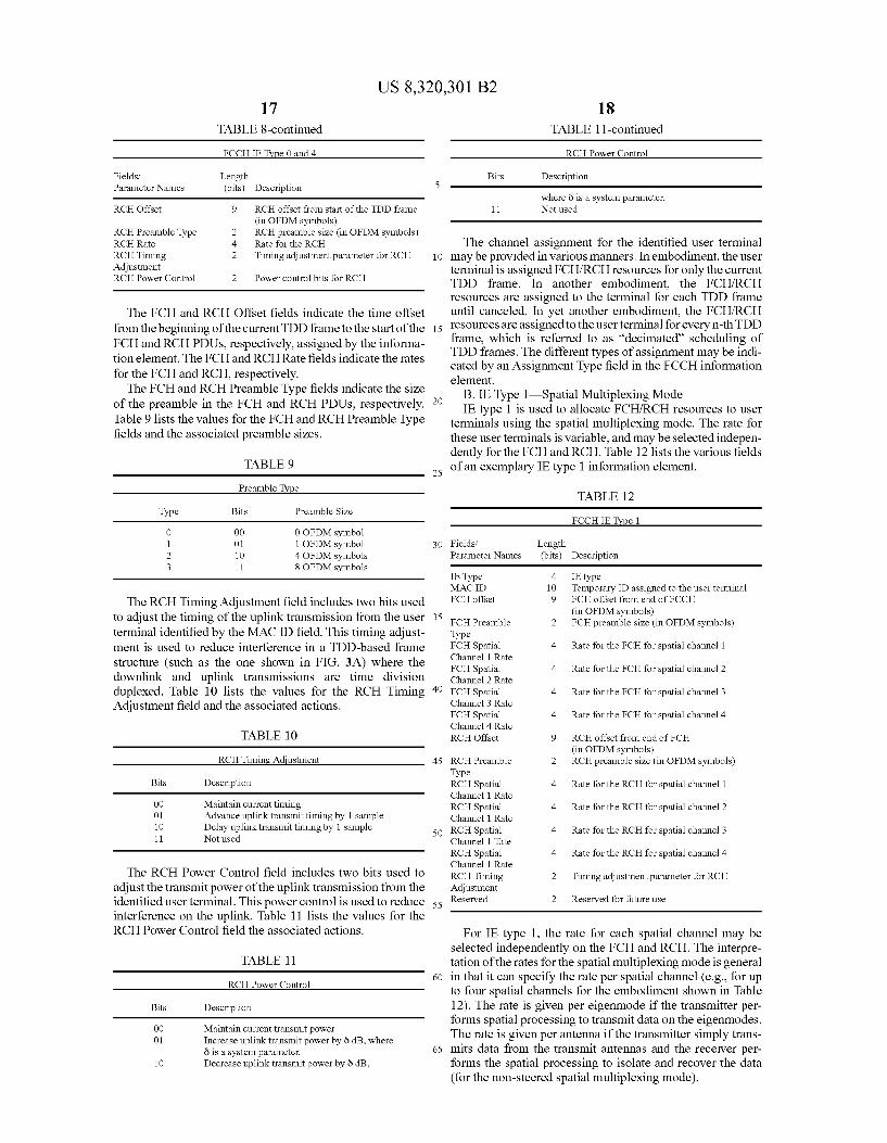
US 8,320,301 B2 17
TABLE 8-continued
FCCHIE Type 0 and 4
Fields. ParameterNames
Length (bits) Description
RCHOffset 9 RCH offset from start of the TDD frame (in OFDM symbols)
RCH Preamble Type 2 RCH preamble size (in OFDM symbols) RCHRate 4 Rate for the RCH RCH Timing 2 Timing adjustment parameter for RCH Adjustment RCH Power Control 2 Power control bits for RCH
The FCH and RCH Offset fields indicate the time offset from the beginning of the current TDD frame to the start of the FCH and RCH PDUs, respectively, assigned by the informa tion element. The FCH and RCHRate fields indicate the rates for the FCH and RCH, respectively.
The FCH and RCH Preamble Type fields indicate the size of the preamble in the FCH and RCH PDUs, respectively. Table 9 lists the values for the FCH and RCH Preamble Type fields and the associated preamble sizes.
TABLE 9
Preamble Type
Type Bits Preamble Size
O OO O OFDM symbol 1 O1 1 OFDM symbol 2 10 4 OFDM symbols 3 11 8 OFDM symbols
The RCH Timing Adjustment field includes two bits used to adjust the timing of the uplink transmission from the user terminal identified by the MAC ID field. This timing adjust ment is used to reduce interference in a TDD-based frame structure (such as the one shown in FIG. 3A) where the downlink and uplink transmissions are time division duplexed. Table 10 lists the values for the RCH Timing Adjustment field and the associated actions.
TABLE 10
RCH Tining Adjustment
Bits Description
OO Maintain current timing O1 Advance uplink transmittiming by 1 sample 10 Delay uplink transmittiming by 1 sample 11 Not used
The RCH Power Control field includes two bits used to adjust the transmit power of the uplink transmission from the identified user terminal. This power control is used to reduce interference on the uplink. Table 11 lists the values for the RCH Power Control field the associated actions.
TABLE 11
RCH Power Control
Bits Description
OO Maintain current transmit power O1 Increase uplink transmit power by 8 dB, where
ö is a system parameter. 10 Decrease uplink transmit power by 8 dB,
10
15
25
30
35
40
45
50
55
60
65
18 TABLE 11-continued
RCH Power Control
Bits Description
where 8 is a System parameter. 11 Not used
The channel assignment for the identified user terminal may be provided in various manners. In embodiment, the user terminal is assigned FCH/RCH resources for only the current TDD frame. In another embodiment, the FCH/RCH resources are assigned to the terminal for each TDD frame until canceled. In yet another embodiment, the FCH/RCH resources areassigned to the user terminal for every n-th TDD frame, which is referred to as “decimated scheduling of TDD frames. The different types of assignment may be indi cated by an Assignment Type field in the FCCH information element.
B. IE Type 1—Spatial Multiplexing Mode IE type 1 is used to allocate FCH/RCH resources to user
terminals using the spatial multiplexing mode. The rate for these user terminals is variable, and may be selected indepen dently for the FCH and RCH. Table 12 lists the various fields of an exemplary IE type 1 information element.
TABLE 12
CCHIETYDel
Fields. Length Parameter Names (bits) Description
E. Type 4 E type MAC ID 10 Temporary ID assigned to the user terminal FCH offset 9 FCH offset from end of FCCH
(in OFDM symbols) FCH Preamble 2 FCH preamble size (in OFDM symbols) Type FCHSpatia 4 Rate for the FCH for spatial channel 1 Channel 1 Rate FCHSpatia 4 Rate for the FCH for spatial channel 2 Channel 2 Rate FCHSpatia 4 Rate for the FCH for spatial channel 3 Channel 3 Rate FCHSpatia 4 Rate for the FCH for spatial channel 4 Channel 4 Rate RCHOffset 9 RCH offset from end of FCH
(in OFDM symbols) RCH Preamble 2 RCH preamble size (in OFDM symbols) Type RCH Spatia 4 Rate for the RCH for spatial channel 1 Channel 1 Rate RCH Spatia 4 Rate for the RCH for spatial channel 2 Channel 1 Rate RCH Spatia 4 Rate for the RCH for spatial channel 3 Channel 1 Tate RCH Spatia 4 Rate for the RCH for spatial channel 4 Channel 1 Rate RCH Timing 2 Timing adjustment parameter for RCH Adjustment Reserved 2 Reserved for future use
For IE type 1, the rate for each spatial channel may be selected independently on the FCH and RCH. The interpre tation of the rates for the spatial multiplexing mode is general in that it can specify the rate per spatial channel (e.g., for up to four spatial channels for the embodiment shown in Table 12). The rate is given per eigenmode if the transmitter per forms spatial processing to transmit data on the eigenmodes. The rate is given per antenna if the transmitter simply trans mits data from the transmit antennas and the receiver per forms the spatial processing to isolate and recover the data (for the non-steered spatial multiplexing mode).
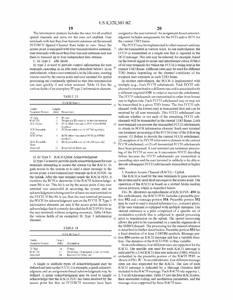
US 8,320,301 B2 19
The information element includes the rates for all enabled spatial channels and Zeros for the ones not enabled. User terminals with less than four transmit antennas set the unused FCH/RCH Spatial Channel Rate fields to zero. Since the access point is equipped with four transmit/receive antennas, user terminals with more than four transmit antennas may use them to transmit up to four independent data streams.
C. IEType 2 Idle Mode IE type 2 is used to provide control information for user
terminals operating in an Idle State (described below). In an embodiment, when a user terminal is in the Idle State, steering vectors used by the access point and user terminal for spatial processing are continually updated so that data transmission can start quickly if and when resumed. Table 13 lists the various fields of an exemplary IE type 2 information element.
TABLE 13
CCHIETYDe 2
Fields. Length ParameterNames (bits) Description
IEType 4 E type MAC ID 10 Temporary ID assigned to the user terminal FCHOffset 9 FCH offset from end of FCCH (in OFDM
symbols) FCH Preamble 2 FCH preamble size (in OFDM symbols) Type RCHOffset 9 RCH offset from end of FCH (in OFDM
symbols) RCH Preamble 2 RCH preamble size (in OFDM symobls) Type Reserved 12 Reserved for future use
D. IE Type 3—RACH Quick Acknowledgment IE type 3 is used to provide quick acknowledgment for user
terminals attempting to access the system via the RACH. To gain access to the system or to send a short message to the access point, a user terminal may transmit an RACH PDU on the uplink. After the user terminal sends the RACH PDU, it monitors the BCH to determine if the RACH Acknowledge ment Bit is set. This bit is set by the access point if any user terminal was successful in accessing the system and an acknowledgment is being sent for at least one user terminal on the FCCH. If this bit is set, then the user terminal processes the FCCH for acknowledgment sent on the FCCH. IEType 3 information elements are sent if the access point desires to acknowledge that it correctly decoded the RACHPDUs from the user terminals without assigning resources. Table 14 lists the various fields of an exemplary IE Type 3 information element.
TABLE 1.4
FCCHIEType 3
Fields. Length ParameterNames (bits) Description
IEType 4 IE type MAC ID 10 Temporary ID assigned to user terminal Reserved 34 Reserved for future use
A single or multiple types of acknowledgment may be defined and sent on the FCCH. For example, a quick acknowl edgment and an assignment-based acknowledgment may be defined. A quick acknowledgment may be used to simply acknowledge that the RACH PDU has been received by the access point but that no FCH/RCH resources have been
10
15
25
30
35
40
45
50
55
60
65
20 assigned to the user terminal. An assignment-based acknowl edgment includes assignments for the FCH and/or RCH for the current TDD frame. The FCCH may be implemented in other manners and may
also be transmitted in various ways. In one embodiment, the FCCH is transmitted at a single rate that is signaled in the BCH message. This rate may be selected, for example, based on the lowest signal-to-noise-and-interference ratios (SNRs) of all user terminals for which the FCCH is being sent in the current TDD frame. Different rates may be used for different TDD frames depending on the channel conditions of the recipient user terminals in each TDD frame.
In another embodiment, the FCCH is implemented with multiple (e.g., four) FCCH subchannels. Each FCCH sub channel is transmitted at a different rate and is associated with a different required SNR in order to recover the subchannel. The FCCH subchannels are transmitted in order from lowest rate to highest rate. Each FCCH subchannel may or may not be transmitted in a given TDD frame. The first FCCH sub channel (with the lowest rate) is transmitted first and can be received by all user terminals. This FCCH subchannel can indicate whether or not each of the remaining FCCH sub channels will be transmitted in the current TDD frame. Each user terminal can process the transmitted FCCH subchannels to obtain its FCCH information element. Each user terminal can terminate processing of the FCCH if any of the following occurs: (1) failure to decode the current FCCH subchannel, (2) reception of its FCCH information element in the current FCCH subchannel, or (3) all transmitted FCCH subchannels have been processed. A user terminal can terminate process ing of the FCCH as soon as it encounters FCCH decoding failure because the FCCH subchannels are transmitted at ascending rates and the user terminal is unlikely to be able to decode subsequent FCCH subchannels transmitted at higher rates.
3. Random Access Channel (RACH)—Uplink The RACH is used by the user terminals to gain access to
the system and to send short messages to the access point. The operation of the RACH is based on a slotted Aloha random access protocol, which is described below. FIG.SC illustrates an embodiment of RACH PDU 450. In
this embodiment, the RACH PDU includes a preamble por tion 552 and a message portion 554. Preamble portion 552 may be used to send a steered reference (i.e., a steered pilot), if the user terminal is equipped with multiple antennas. The steered reference is a pilot comprised of a specific set of modulation symbols that is Subjected to spatial processing prior to transmission on the uplink. The spatial processing allows the pilot to be transmitted on a specific eigenmode of the MIMO channel. The processing for the steered reference is described in further detail below. Preamble portion 552 has a fixed duration of at least 2 OFDM symbols. Message por tion 554 carries an RACH message and has a variable dura tion. The duration of the RACH PDU is thus variable.
In an embodiment, four different rates are supported for the RACH. The specific rate used for each RACH message is indicated by a 2-bit RACH data rate indicator (DRI), which is embedded in the preamble portion of the RACH PDU, as shown in FIG.5C. In an embodiment, four different message sizes are also supported for the RACH. The size of each RACH message is indicated by a Message Duration field included in the RACH message. Each RACH rate supports 1, 2, 3 or all 4 message sizes. Table 15 lists the four RACH rates, their associated coding and modulation parameters, and the message sizes Supported by these RACH rates.
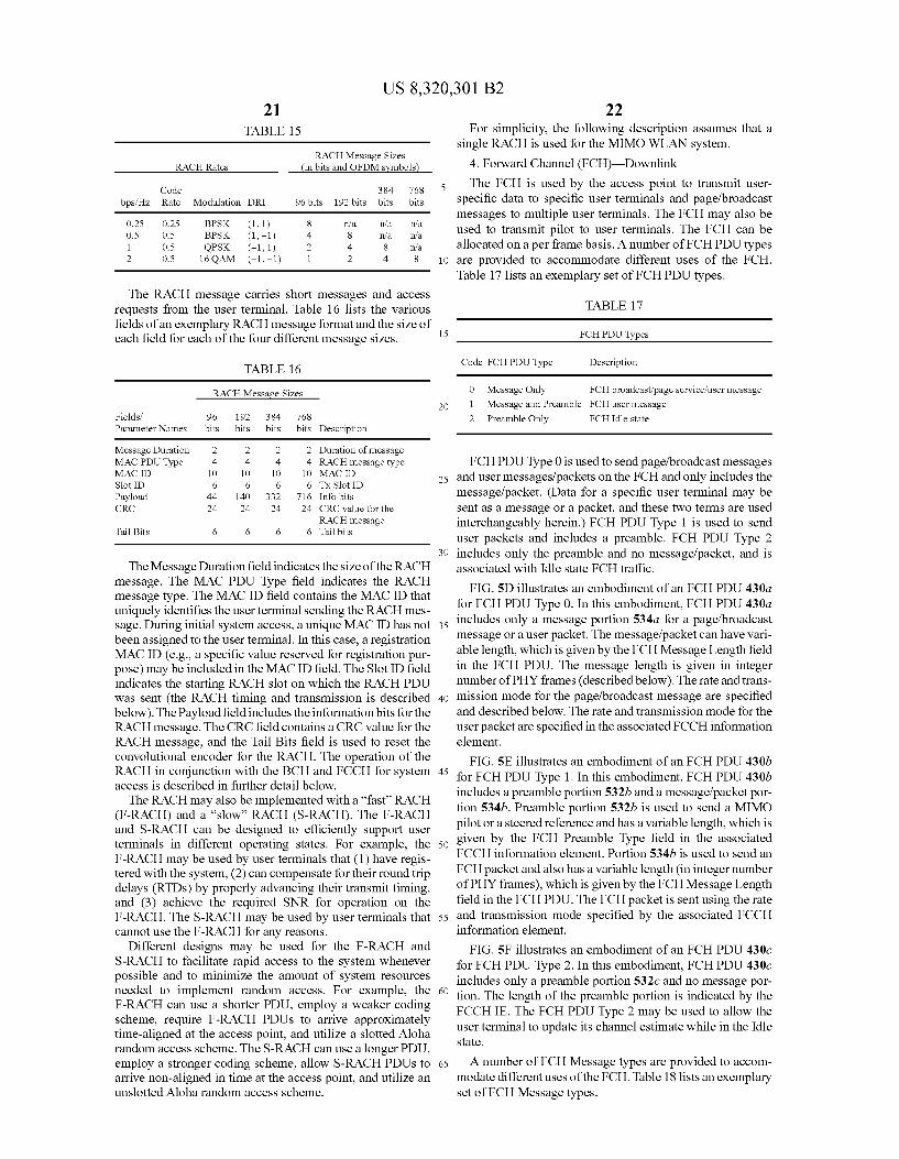
US 8,320,301 B2 21
TABLE 1.5
RACH Message Sizes RACHRates in bits and OFDM symbols
Code 384 768 bps/Hz Rate Modulation DRI 96 bits 192 bits bits bits
O.25 O.25 BPSK (1,1) 8 na na na O.S O.S BPSK (1,-1) 4 8 na na 1 O.S QPSK (-1, 1) 2 4 8 na 2 O.S 16 QAM (-1, -1) 1 2 4 8
The RACH message carries short messages and access requests from the user terminal. Table 16 lists the various fields of an exemplary RACH message format and the size of each field for each of the four different message sizes.
TABLE 16
RACH MessageSizes
Fields. 96 192 384 768 ParameterNames bits bits bits bits Description
Message Duration 2 2 2 2. Duration of message MAC PDU Type 4 4 4 4 RACH message type MAC ID 10 10 10 10 MAC ID Slot ID 6 6 6 6 Tx Slot ID Payload 44 140 332 716 Info bits CRC 24 24 24 24 CRC value for the
RACH message Tail Bits 6 6 6 6 Tail bits
The Message Duration field indicates the size of the RACH message. The MAC PDU Type field indicates the RACH message type. The MAC ID field contains the MAC ID that uniquely identifies the user terminal sending the RACH mes sage. During initial system access, a unique MACID has not been assigned to the user terminal. In this case, a registration MAC ID (e.g., a specific value reserved for registration pur pose) may be included in the MAC ID field. The Slot ID field indicates the starting RACH slot on which the RACH PDU was sent (the RACH timing and transmission is described below). The Payload field includes the information bits for the RACH message. The CRC field contains a CRC value for the RACH message, and the Tail Bits field is used to reset the convolutional encoder for the RACH. The operation of the RACH in conjunction with the BCH and FCCH for system access is described in further detail below. The RACH may also be implemented with a “fast” RACH
(F-RACH) and a “slow” RACH (S-RACH). The F-RACH and S-RACH can be designed to efficiently support user terminals in different operating states. For example, the F-RACH may be used by user terminals that (1) have regis tered with the system, (2) can compensate for their round trip delays (RTDs) by properly advancing their transmit timing, and (3) achieve the required SNR for operation on the F-RACH. The S-RACH may be used by user terminals that cannot use the F-RACH for any reasons.
Different designs may be used for the F-RACH and S-RACH to facilitate rapid access to the system whenever possible and to minimize the amount of system resources needed to implement random access. For example, the F-RACH can use a shorter PDU, employ a weaker coding scheme, require F-RACH PDUs to arrive approximately time-aligned at the access point, and utilize a slotted Aloha random access scheme. The S-RACH can use a longer PDU, employ a stronger coding scheme, allow S-RACH PDUs to arrive non-aligned in time at the access point, and utilize an unslotted Aloha random access scheme.
5
10
15
25
30
35
40
45
50
55
60
65
22 For simplicity, the following description assumes that a
single RACH is used for the MIMO WLAN system. 4. Forward Channel (FCH)—Downlink The FCH is used by the access point to transmit user
specific data to specific user terminals and page/broadcast messages to multiple user terminals. The FCH may also be used to transmit pilot to user terminals. The FCH can be allocated on a per frame basis. A number of FCH PDU types are provided to accommodate different uses of the FCH. Table 17 lists an exemplary set of FCH PDU types.
TABLE 17
FCH PDU Types
Code FCH PDU Type Description
O Message Only FCH broadcast page servicefuser message 1 Message and Preamble FCH user message 2 Preamble Only FCHIdle state
FCH PDU Type 0 is used to send page/broadcast messages and user messages/packets on the FCH and only includes the message/packet. (Data for a specific user terminal may be sent as a message or a packet, and these two terms are used interchangeably herein.) FCH PDU Type 1 is used to send user packets and includes a preamble. FCH PDU Type 2 includes only the preamble and no message/packet, and is associated with Idle state FCH traffic.
FIG.SD illustrates an embodiment of an FCH PDU 430a for FCH PDU Type 0. In this embodiment, FCH PDU 430a includes only a message portion 534a for a page/broadcast message or a user packet. The message/packet can have vari able length, which is given by the FCH Message Length field in the FCH PDU. The message length is given in integer number of PHY frames (described below). The rate and trans mission mode for the page/broadcast message are specified and described below. The rate and transmission mode for the user packet are specified in the associated FCCH information element.
FIG. SE illustrates an embodiment of an FCH PDU 430b for FCH PDU Type 1. In this embodiment, FCH PDU 430b includes a preamble portion 532b and a message/packet por tion 534b. Preamble portion 532b is used to send a MIMO pilot or a steered reference and has a variable length, which is given by the FCH Preamble Type field in the associated FCCH information element. Portion 534b is used to send an FCH packet and also has a variable length (in integer number of PHY frames), which is given by the FCH Message Length field in the FCH PDU. The FCH packet is sent using the rate and transmission mode specified by the associated FCCH information element.
FIG.SF illustrates an embodiment of an FCH PDU 430c for FCH PDU Type 2. In this embodiment, FCH PDU 430c includes only a preamble portion 532c and no message por tion. The length of the preamble portion is indicated by the FCCHIE. The FCH PDU Type 2 may be used to allow the user terminal to update its channel estimate while in the Idle State.
A number of FCH Message types are provided to accom modate different uses of the FCH. Table 18 lists an exemplary set of FCH Message types.
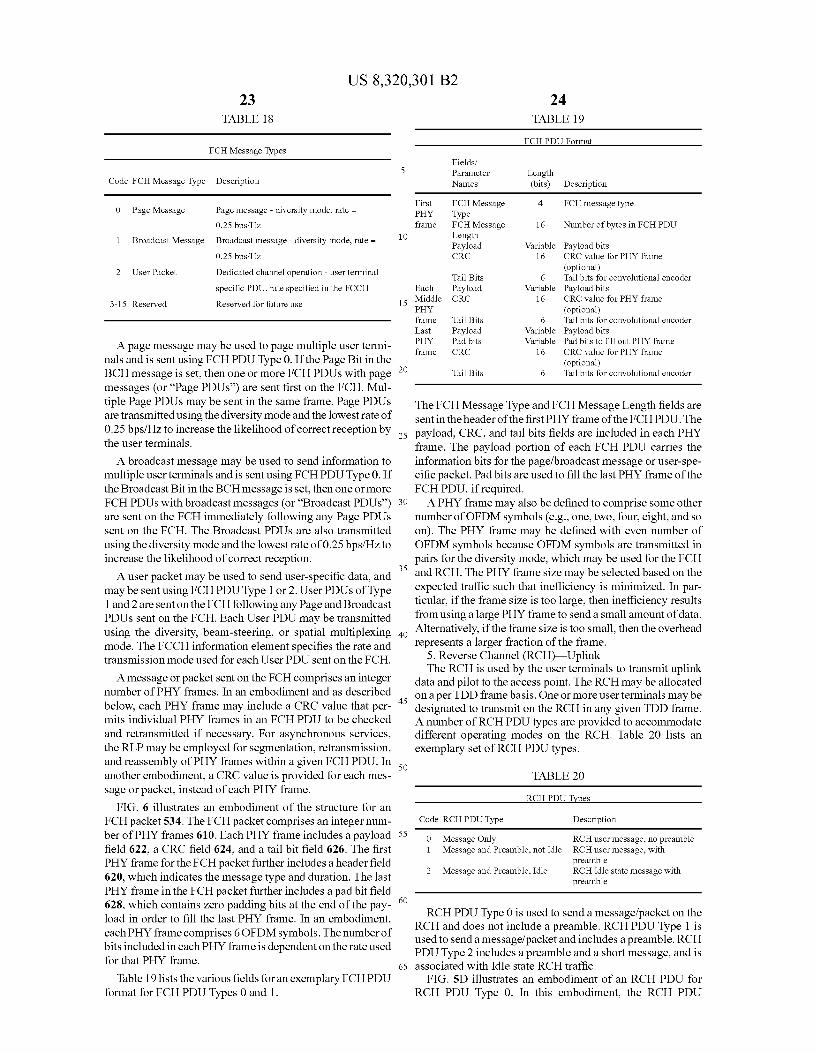
US 8,320,301 B2 23
TABLE 18
FCH Message Types
Code FCH Message Type Description
O Page Message Page message - diversity mode, rate = 0.25bps/Hz Broadcast message - diversity mode, rate = 1 Broadcast Message
2 User Packet Dedicated channel operation - user terminal
specific PDU, rate specified in the FCCH 3-15 Reserved Reserved for future use
A page message may be used to page multiple user termi nals and is sent using FCH PDU Type 0. If the Page Bit in the BCH message is set, then one or more FCHPDUs with page messages (or “Page PDUs) are sent first on the FCH. Mul tiple Page PDUs may be sent in the same frame. Page PDUs are transmitted using the diversity mode and the lowest rate of 0.25bps/Hz to increase the likelihood of correct reception by the user terminals.
A broadcast message may be used to send information to multiple user terminals and is sent using FCH PDU Type 0. If the Broadcast Bit in the BCH message is set, then one or more FCHPDUs with broadcast messages (or “Broadcast PDUs) are sent on the FCH immediately following any Page PDUs sent on the FCH. The Broadcast PDUs are also transmitted using the diversity mode and the lowest rate of 0.25bps/Hz to increase the likelihood of correct reception. A user packet may be used to send user-specific data, and
may be sent using FCHPDU Type 1 or 2. User PDUs of Type 1 and 2 are sent on the FCH following any Page and Broadcast PDUs sent on the FCH. Each User PDU may be transmitted using the diversity, beam-steering, or spatial multiplexing mode. The FCCH information element specifies the rate and transmission mode used for each User PDU sent on the FCH.
A message or packet sent on the FCH comprises an integer number of PHY frames. In an embodiment and as described below, each PHY frame may include a CRC value that per mits individual PHY frames in an FCH PDU to be checked and retransmitted if necessary. For asynchronous services, the RLP may be employed for segmentation, retransmission, and reassembly of PHY frames within a given FCH PDU. In another embodiment, a CRC value is provided for each mes sage or packet, instead of each PHY frame.
FIG. 6 illustrates an embodiment of the structure for an FCH packet 534. The FCH packet comprises an integer num ber of PHY frames 610. Each PHY frame includes a payload field 622, a CRC field 624, and a tail bit field 626. The first PHY frame for the FCH packet further includes aheader field 620, which indicates the message type and duration. The last PHY frame in the FCH packet further includes a pad bit field 628, which contains zero padding bits at the end of the pay load in order to fill the last PHY frame. In an embodiment, each PHY frame comprises 6 OFDM symbols. The number of bits included in each PHY frame is dependent on the rate used for that PHY frame.
Table 19 lists the various fields for an exemplary FCHPDU format for FCH PDU Types 0 and 1.
10
15
25
30
35
40
45
50
55
60
65
24 TABLE 19
FCHPDUFormat
ields Parameter Length Names (bits) Description
First FCH Message 4 FCH message type PHY Type frame FCH Message 16 Number of bytes in FCH PDU
Length Payload Variable Payload bits CRC 16 CRC value for PHY frame
(optional) Tail Bits 6 Tail bits for convolutional encoder
Each Payload Variable Payload bits Middle CRC 16 CRC value for PHY frame PHY (optional) frame Tail Bits 6 Tail bits for convolutional encoder Last Payload Variable Payload bits PHY Padbits Variable Padbits to fill out PHY frame frame CRC 16 CRC value for PHY frame
(optional) Tail Bits 6 Tail bits for convolutional encoder
The FCH Message Type and FCH Message Length fields are sent in the header of the first PHY frame of the FCHPDU. The payload, CRC, and tail bits fields are included in each PHY frame. The payload portion of each FCH PDU carries the information bits for the page/broadcast message or user-spe cific packet. Padbits are used to fill the last PHY frame of the FCH PDU, if required. A PHY frame may also be defined to comprise some other
number of OFDM symbols (e.g., one, two, four, eight, and so on). The PHY frame may be defined with even number of OFDM symbols because OFDM symbols are transmitted in pairs for the diversity mode, which may be used for the FCH and RCH. The PHY frame size may be selected based on the expected traffic Such that inefficiency is minimized. In par ticular, if the frame size is too large, then inefficiency results from using a large PHY frame to send a small amount of data. Alternatively, if the frame size is too small, then the overhead represents a larger fraction of the frame.
5. Reverse Channel (RCH) Uplink The RCH is used by the user terminals to transmit uplink
data and pilot to the access point. The RCH may be allocated on a per TDD frame basis. One or more user terminals may be designated to transmit on the RCH in any given TDD frame. A number of RCH PDU types are provided to accommodate different operating modes on the RCH. Table 20 lists an exemplary set of RCH PDU types.
TABLE 20
RCH PDU Types
Code RCH PDU Type Description
O Message Only RCH user message, no preamble 1 Message and Preamble, not Idle RCH user message, with
preamble 2 Message and Preamble, Idle RCH Idle state message with
preamble
RCH PDU Type 0 is used to send a message/packet on the RCH and does not include a preamble. RCH PDU Type 1 is used to send a message/packet and includes a preamble. RCH PDU Type 2 includes a preamble and a short message, and is associated with Idle state RCH traffic.
FIG. SD illustrates an embodiment of an RCH PDU for RCH PDU Type 0. In this embodiment, the RCH PDU
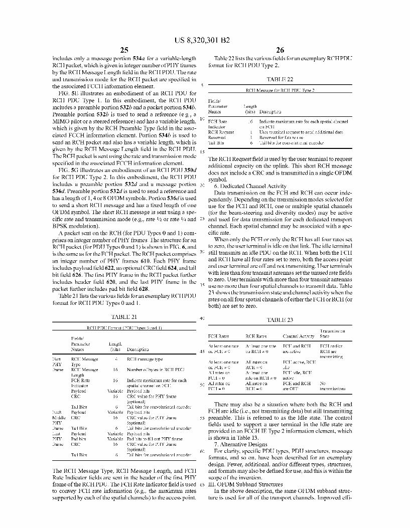
US 8,320,301 B2 25
includes only a message portion 534a for a variable-length RCH packet, which is given in integer number of PHY frames by the RCH Message Length field in the RCH PDU. The rate and transmission mode for the RCH packet are specified in the associated FCCH information element.
FIG. SE illustrates an embodiment of an RCH PDU for RCH PDU Type 1. In this embodiment, the RCH PDU includes a preamble portion 532b and a packet portion 534b. Preamble portion 532b is used to send a reference (e.g., a MIMO pilot or a steered reference) and has a variable length, which is given by the RCH Preamble Type field in the asso ciated FCCH information element. Portion 534b is used to send an RCH packet and also has a variable length, which is given by the RCH Message Length field in the RCH PDU. The RCH packet is sent using the rate and transmission mode specified in the associated FCCH information element.
FIG. 5G illustrates an embodiment of an RCH PDU 350d for RCH PDU Type 2. In this embodiment, the RCH PDU includes a preamble portion 532d and a message portion 536d. Preamble portion 532d is used to send a reference and has a length of 1,4 or 8 OFDM symbols. Portion 536d is used to send a short RCH message and has a fixed length of one OFDM symbol. The short RCH message is sent using a spe cific rate and transmission mode (e.g., rate /2 or rate 4 and BPSK modulation). A packet sent on the RCH (for PDU Types 0 and 1) com
prises an integer number of PHY frames. The structure for an RCH packet (for PDU Types 0 and 1) is shown in FIG. 6, and is the same as for the FCH packet. The RCH packet comprises an integer number of PHY frames 610. Each PHY frame includes payload field 622, an optional CRC field 624, and tail bit field 626. The first PHY frame in the RCH packet further includes header field 620, and the last PHY frame in the packet further includes pad bit field 628.
Table 21 lists the various fields for an exemplary RCHPDU format for RCH PDU Types 0 and 1.
TABLE 21
RCH PDU Format (PDU Types 0 and 1
ields Parameter Length Names (bits) Description
Fisrt RCH Message 4 RCH message type PHY Type frame RCH Message 16 Number of bytes in RCH PDU
Length FCHRate 16 indicate maximum rate for each indicator spatial channel on FCH Payload Variable Payload bits CRC 16 CRC value for PHY frame
(optional) Tail Bits 6 Tail bits for convolutional encoder
Each Payload Variable Payload bits Middle CRC 16 CRC value for PHY frame PHY (optional) frame Tail Bits 6 Tail bits for convolutional encoder Last Payload Variable Payload bits PHY Pad bits Variable Padbits to fill out PHY frame frame CRC 16 CRC value for PHY frame
(optional) Tail Bits 6 Tail bits for convolutional encoder
The RCH Message Type, RCH Message Length, and FCH Rate Indicator fields are sent in the header of the first PHY frame of the RCHPDU. The FCH Rate Indicator field is used to convey FCH rate information (e.g., the maximum rates Supported by each of the spatial channels) to the access point.
5
10
15
25
30
35
40
45
50
55
60
65
26 Table 22 lists the various fields for an exemplary RCHPDU
format for RCH PDU Type 2.
TABLE 22
RCH Message for RCH PDU Type 2
Fields. Parameter Length Names (bits) Description
FCHRate 16 Indicate maximum rate for each spatial channel Indicator on FCH RCH Request 1 User terminal request to send additional data Reserved 1 Reserved for future use Tail Bits 6 Tail bits for convolutional encoder
The RCH Request field is used by the user terminal to request additional capacity on the uplink. This short RCH message does not include a CRC and is transmitted in a single OFDM symbol.
6. Dedicated Channel Activity Data transmission on the FCH and RCH can occur inde
pendently. Depending on the transmission modes selected for use for the FCH and RCH, one or multiple spatial channels (for the beam-steering and diversity modes) may be active and used for data transmission for each dedicated transport channel. Each spatial channel may be associated with a spe cific rate. When only the FCH or only the RCH has all four rates set
to zero, the user terminal is idle on that link. The idle terminal Still transmits an idle PDU on the RCH. When both the FCH and RCH have all four rates set to zero, both the access point and user terminal are off and not transmitting. User terminals with less than four transmit antennas set the unused rate fields to Zero. User terminals with more than four transmit antennas use no more than four spatial channels to transmit data. Table 23 shows the transmission state and channel activity when the rates on all four spatial channels of either the FCH or RCH (or both) are set to Zero.
TABLE 23
Transmission FCHRates RCHRates Channel Activity State
At least one rate At least one rate FCH and RCH FCH and for on FCHz O on RCHz O are active RCH are
transmitting At least one rate All rates on FCH active, RCH on FCHz O RCH = 0 idle All rates on At least one FCH idle, RCH FCH - O rate on RCHz O active All rates on All rates on FCH and RCH No FCH - O RCH = 0 are OFF transmissions
There may also be a situation where both the RCH and FCH are idle (i.e., not transmitting data) but still transmitting preamble. This is referred to as the Idle state. The control fields used to support a user terminal in the Idle state are provided in an FCCHIE Type 2 information element, which is shown in Table 13.
7. Alternative Designs For clarity, specific PDU types, PDU structures, message
formats, and so on, have been described for an exemplary design. Fewer, additional, and/or different types, structures, and formats may also be defined for use, and this is within the Scope of the invention. III. OFDM Subband Structures
In the above description, the same OFDM subband struc ture is used for all of the transport channels. Improved effi
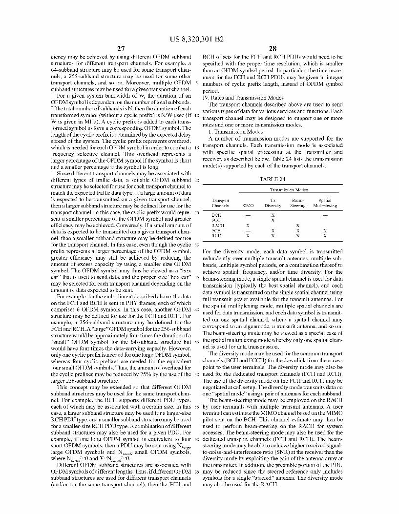
US 8,320,301 B2 27
ciency may be achieved by using different OFDM Subband structures for different transport channels. For example, a 64-Subband structure may be used for Some transport chan nels, a 256-subband structure may be used for some other transport channels, and so on. Moreover, multiple OFDM Subband structures may be used for a given transport channel.
For a given system bandwidth of W, the duration of an OFDM symbol is dependent on the number of total subbands. If the total number of subbands is N, then the duration of each transformed symbol (without a cyclic prefix) is N/W usec (if W is given in MHz). A cyclic prefix is added to each trans formed symbol to form a corresponding OFDM symbol. The length of the cyclic prefix is determined by the expected delay spread of the system. The cyclic prefix represents overhead, which is needed for each OFDM symbol in order to combat a frequency selective channel. This overhead represents a larger percentage of the OFDM symbol if the symbol is short and a smaller percentage if the symbol is long.
Since different transport channels may be associated with different types of traffic data, a suitable OFDM Subband structure may be selected for use for each transport channel to match the expected traffic data type. If a large amount of data is expected to be transmitted on a given transport channel, then a larger subband structure may be defined for use for the transport channel. In this case, the cyclic prefix would repre sent a smaller percentage of the OFDM symbol and greater efficiency may be achieved. Conversely, if a small amount of data is expected to be transmitted on a given transport chan nel, than a smaller subband structure may be defined for use for the transport channel. In this case, even though the cyclic prefix represents a larger percentage of the OFDM symbol, greater efficiency may still be achieved by reducing the amount of excess capacity by using a smaller size OFDM symbol. The OFDM symbol may thus be viewed as a “box car that is used to send data, and the proper size “box car' may be selected for each transport channel depending on the amount of data expected to be sent.
For example, for the embodiment described above, the data on the FCH and RCH is sent in PHY frames, each of which comprises 6 OFDM symbols. In this case, another OFDM structure may be defined for use for the FCH and RCH. For example, a 256-subband structure may be defined for the FCH and RCH. A“large” OFDM symbol for the 256-subband structure would be approximately four times the duration of a “small' OFDM symbol for the 64-subband structure but would have four times the data-carrying capacity. However, only one cyclic prefix is needed for one large OFDM symbol, whereas four cyclic prefixes are needed for the equivalent four small OFDM symbols. Thus, the amount of overhead for the cyclic prefixes may be reduced by 75% by the use of the larger 256-subband structure.
This concept may be extended so that different OFDM Subband structures may be used for the same transport chan nel. For example, the RCH supports different PDU types, each of which may be associated with a certain size. In this case, a larger Subband structure may be used for a larger-size RCHPDU type, and a smaller subband structure may be used for a smaller-size RCHPDU type. A combination of different subband structures may also be used for a given PDU. For example, if one long OFDM symbol is equivalent to four short OFDM symbols, then a PDU may be sent using N. large OFDM symbols and N. Small OFDM symbols, where N20 and 32N 720.
Different OFDM Subband structures are associated with OFDM symbols of different lengths. Thus, if different OFDM subband structures are used for different transport channels (and/or for the same transport channel), then the FCH and
10
15
25
30
35
40
45
50
55
60
65
28 RCH offsets for the FCH and RCH PDUs would need to be specified with the proper time resolution, which is smaller than an OFDM symbol period. In particular, the time incre ment for the FCH and RCH PDUs may be given in integer numbers of cyclic prefix length, instead of OFDM symbol period. IV. Rates and Transmission Modes The transport channels described above are used to send
various types of data for various services and functions. Each transport channel may be designed to Support one or more rates and one or more transmission modes.
1. Transmission Modes A number of transmission modes are Supported for the
transport channels. Each transmission mode is associated with specific spatial processing at the transmitter and receiver, as described below. Table 24 lists the transmission mode(s) supported by each of the transport channels.
TABLE 24
Transmission Modes
Transport Tx Beam- Spatial Channels SIMO Diversity Steering Multiplexing
BCH X FCCH X RACH X X FCH X X X RCH X X X X
For the diversity mode, each data symbol is transmitted redundantly over multiple transmit antennas, multiple sub bands, multiple symbol periods, or a combination thereof to achieve spatial, frequency, and/or time diversity. For the beam-steering mode, a single spatial channel is used for data transmission (typically the best spatial channel), and each data symbol is transmitted on the single spatial channel using full transmit power available for the transmit antennas. For the spatial multiplexing mode, multiple spatial channels are used for data transmission, and each data symbol is transmit ted on one spatial channel, where a spatial channel may correspond to an eigenmode, a transmit antenna, and so on. The beam-steering mode may be viewed as a special case of the spatial multiplexing mode whereby only one spatial chan nel is used for data transmission. The diversity mode may be used for the common transport
channels (BCH and FCCH) for the downlink from the access point to the user terminals. The diversity mode may also be used for the dedicated transport channels (FCH and RCH). The use of the diversity mode on the FCH and RCH may be negotiated at call setup. The diversity mode transmits data on one “spatial mode” using a pair of antennas for each Subband. The beam-steering mode may be employed on the RACH
by user terminals with multiple transmit antennas. A user terminal can estimate the MIMO channel based on the MIMO pilot sent on the BCH. This channel estimate may then be used to perform beam-steering on the RACH for system accesses. The beam-steering mode may also be used for the dedicated transport channels (FCH and RCH). The beam steering mode may be able to achieve higher received signal to-noise-and-interference ratio (SNR) at the receiver than the diversity mode by exploiting the gain of the antenna array at the transmitter. In addition, the preamble portion of the PDU may be reduced since the steered reference only includes symbols for a single “steered antenna. The diversity mode may also be used for the RACH.
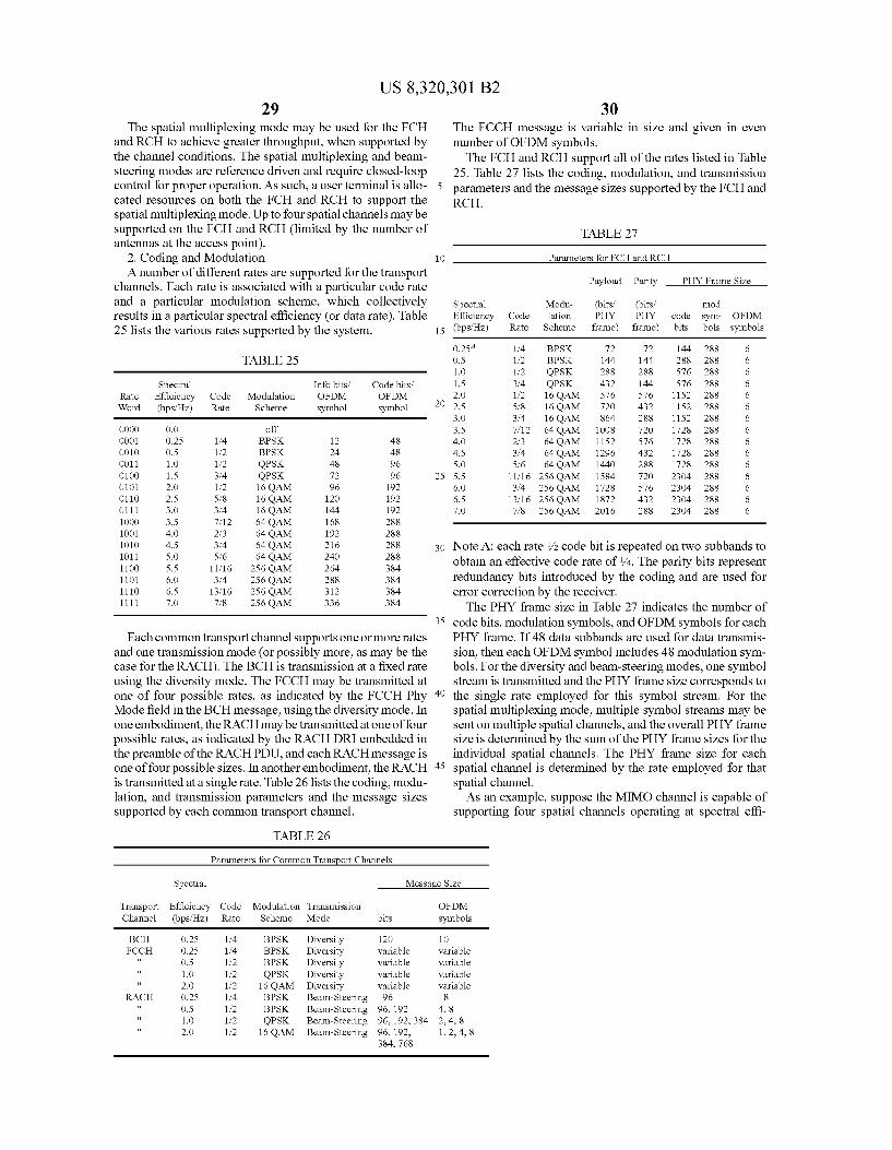
US 8,320,301 B2 29
The spatial multiplexing mode may be used for the FCH and RCH to achieve greater throughput, when supported by the channel conditions. The spatial multiplexing and beam steering modes are reference driven and require closed-loop control for proper operation. As such, a user terminal is allo cated resources on both the FCH and RCH to support the spatial multiplexing mode. Up to four spatial channels may be supported on the FCH and RCH (limited by the number of antennas at the access point).
2. Coding and Modulation A number of different rates are supported for the transport
channels. Each rate is associated with a particular code rate and a particular modulation scheme, which collectively results in a particular spectral efficiency (or data rate). Table 25 lists the various rates supported by the system.
TABLE 25
Spectral Info bits Code bits. Rate Efficiency Code Modulation OFDM OFDM Word (bps/Hz) Rate Scheme symbol symbol
OOOO O.O Off OOO1 O.25 1.f4 BPSK 12 48 OO10 O.S 1.2 BPSK 24 48 OO11 1.O 1.2 QPSK 48 96 O1 OO 1.5 3f4 QPSK 72 96 O101 2.0 1.2 16 QAM 96 192 O110 2.5 5.8 16 QAM 120 192 O111 3.0 3f4 16 QAM 144 192 1OOO 3.5 7,12 64 QAM 168 288 1001 4.0 2.3 64 QAM 192 288 1010 4.5 3f4 64 QAM 216 288 1011 S.O 5.6 64 QAM 240 288 1100 5.5 11.16 256 QAM 264 384 1101 6.O 3f4 256 QAM 288 384 1110 6.5 13,16 256 QAM 312 384 1111 7.0 7/8 256 QAM 336 384
Each common transport channel Supports one or more rates and one transmission mode (or possibly more, as may be the case for the RACH). The BCH is transmission at a fixed rate using the diversity mode. The FCCH may be transmitted at one of four possible rates, as indicated by the FCCH Phy Mode field in the BCH message, using the diversity mode. In one embodiment, the RACH may be transmitted at one of four possible rates, as indicated by the RACH DRI embedded in the preamble of the RACHPDU, and each RACH message is one of four possible sizes. In another embodiment, the RACH is transmitted at a single rate. Table 26 lists the coding, modu lation, and transmission parameters and the message sizes Supported by each common transport channel.
TABLE 26
10
15
25
30
35
40
45
30 The FCCH message is variable in size and given in even number of OFDM symbols. The FCH and RCH support all of the rates listed in Table
25. Table 27 lists the coding, modulation, and transmission parameters and the message sizes Supported by the FCH and RCH.
TABLE 27
Parameters for FCH and RCH
Payload Parity PHY Frame Size
Spectral Modu- (bits (bits mod Efficiency Code lation PHY PHY code sym- OFDM (bps/Hz) Rate Scheme frame) frame) bits bols symbols
O.251 1f4 BPSK 72 72 144 288 6 O.S 1.2 BPSK 144 144 288 288 6 1.O 1.2 QPSK 288 288 576 288 6 1.5 3f4 QPSK 432 144 576 288 6 2.0 1.2 16 QAM 576 576 1152 288 6 2.5 5.8 16 QAM 720 432 1152 288 6 3.0 3f4 16 QAM 864 288 1152 288 6 3.5 7/12 64 QAM 1008 720 1728 288 6 4.0 2.3 64 QAM 1152 576 1728 288 6 4.5 3f4 64 QAM 1296 432 1728 288 6 S.O 5.6 64 QAM 1440 288 1728 288 6 5.5 11/16 256 QAM 1584 72O 2304 288 6 6.O 3/4 256 QAM 1728 576. 2304 288 6 6.5 13/16 256 QAM 1872 432 2304 288 6 7.0 7/8 256 QAM 2016 288 2304 288 6
Note A: each rate /2 code bit is repeated on two subbands to obtain an effective code rate of/4. The parity bits represent redundancy bits introduced by the coding and are used for error correction by the receiver. The PHY frame size in Table 27 indicates the number of
code bits, modulation symbols, and OFDM symbols for each PHY frame. If 48 data Subbands are used for data transmis sion, then each OFDM symbol includes 48 modulation sym bols. For the diversity and beam-steering modes, one symbol stream is transmitted and the PHY frame size corresponds to the single rate employed for this symbol stream. For the spatial multiplexing mode, multiple symbol streams may be sent on multiple spatial channels, and the overall PHY frame size is determined by the sum of the PHY frame sizes for the individual spatial channels. The PHY frame size for each spatial channel is determined by the rate employed for that spatial channel. As an example, suppose the MIMO channel is capable of
Supporting four spatial channels operating at spectral effi
Parameters for Common Transport Channels
Spectral
Transport Efficiency Code Modulation Transmission Channel (bps/Hz) Rate Scheme Mode bits
BCH O.25 1.f4 BPSK Diversity 120 FCCH O.25 1.f4 BPSK Diversity variable
O.S 1.2 BPSK Diversity variable 1.O 1.2 QPSK Diversity variable 2.0 1.2 16 QAM Diversity variable
RACH O.25 1.f4 BPSK Beam-Steering 96 O.S 1.2 BPSK Beam-Steering 96, 192 1.O 1.2 QPSK Beam-Steering 96, 192,384 2.0 1.2 16 QAM Beam-Steering 96, 192,
384,768
Message Size
OFDM symbols
variable variable variable variable 8
4, 2, 1
8 , 4, 8
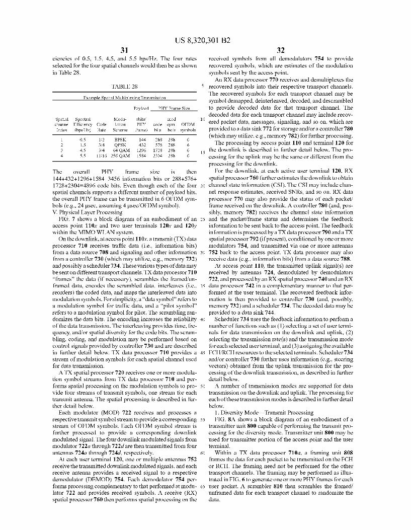
US 8,320,301 B2 31
ciencies of 0.5, 1.5, 4.5, and 5.5 bps/Hz. The four rates selected for the four spatial channels would then be as shown in Table 28.
TABLE 28
Example Spatial Multiplexing Transmission
Payload PHY Frame Size
Spatial Spectral Modu- (bits mod channel Efficiency Code lation PHY code sym- OFDM Index (bps/Hz) Rate Scheme frame) bits bols symbols
1 O.S 1.2 BPSK 144 288 288 6 2 1.5 3f4 QPSK 432 576 288 6 3 4.5 3f4 64 QAM 1296 1728 288 6 4 5.5 11/16 256 QAM 1584. 2304 288 6
The overall PHY frame size is then 144+432+1296+1584=3456 information bits or 288+576-- 1728+2304–4896 code bits. Even though each of the four spatial channels Supports a different number of payload bits, the overall PHY frame can be transmitted in 6 OFDM sym bols (e.g., 24 usec, assuming 4 usec?.OFDM symbol). V. Physical Layer Processing
FIG. 7 shows a block diagram of an embodiment of an access point 110x and two user terminals 120x and 120y within the MIMO WLAN system. On the downlink, at access point 110x, a transmit (TX) data
processor 710 receives traffic data (i.e., information bits) from a data source 708 and signaling and other information from a controller 730 (which may utilize, e.g., memory 732) and possibly a scheduler 734. These various types of data may be sent on different transport channels. TX data processor 710 “frames' the data (if necessary), scrambles the framed/un framed data, encodes the scrambled data, interleaves (i.e., reorders) the coded data, and maps the interleaved data into modulation symbols. For simplicity, a “data symbol refers to a modulation symbol for traffic data, and a “pilot symbol refers to a modulation symbol for pilot. The scrambling ran domizes the data bits. The encoding increases the reliability of the data transmission. The interleaving provides time, fre quency, and/or spatial diversity for the code bits. The scram bling, coding, and modulation may be performed based on control signals provided by controller 730 and are described in further detail below. TX data processor 710 provides a stream of modulation symbols for each spatial channel used for data transmission. ATX spatial processor 720 receives one or more modula
tion symbol streams from TX data processor 710 and per forms spatial processing on the modulation symbols to pro vide four streams of transmit symbols, one stream for each transmit antenna. The spatial processing is described in fur ther detail below.
Each modulator (MOD) 722 receives and processes a respective transmit symbol stream to provide a corresponding stream of OFDM symbols. Each OFDM symbol stream is further processed to provide a corresponding downlink modulated signal. The four downlink modulated signals from modulator 722a through 722d are then transmitted from four antennas 724a through 724d, respectively.
At each user terminal 120, one or multiple antennas 752 receive the transmitted downlink modulated signals, and each receive antenna provides a received signal to a respective demodulator (DEMOD) 754. Each demodulator 754 per forms processing complementary to that performed at modu lator 722 and provides received symbols. A receive (RX) spatial processor 760 then performs spatial processing on the
10
15
25
30
35
40
45
50
55
60
65
32 received symbols from all demodulators 754 to provide recovered symbols, which are estimates of the modulation symbols sent by the access point. An RX data processor 770 receives and demultiplexes the
recovered symbols into their respective transport channels. The recovered symbols for each transport channel may be symbol demapped, deinterleaved, decoded, and descrambled to provide decoded data for that transport channel. The decoded data for each transport channel may include recov ered packet data, messages, signaling, and so on, which are provided to a data sink 772 for storage and/or a controller 780 (which may utilize, e.g., memory 782) for further processing. The processing by access point 110 and terminal 120 for
the downlink is described in further detail below. The pro cessing for the uplink may be the same or different from the processing for the downlink.
For the downlink, at each active user terminal 120, RX spatial processor 760 further estimates the downlink to obtain channel state information (CSI). The CSI may include chan nel response estimates, received SNRs, and so on. RX data processor 770 may also provide the status of each packet/ frame received on the downlink. A controller 780 (and, pos sibly, memory 782) receives the channel state information and the packet/frame status and determines the feedback information to be sent back to the access point. The feedback information is processed by a TX data processor 790 and a TX spatial processor 792 (if present), conditioned by one or more modulators 754, and transmitted via one or more antennas 752 back to the access point. TX data processor may also receive data (e.g., information bits) from a data source 788. At access point 110, the transmitted uplink signal(s) are
received by antennas 724, demodulated by demodulators 722, and processed by an RX spatial processor 740 and an RX data processor 742 in a complementary manner to that per formed at the user terminal. The recovered feedback infor mation is then provided to controller 730 (and, possibly, memory 732) and a scheduler 734. The decoded data may be provided to a data sink 744.
Scheduler 734 uses the feedback information to perform a number of functions such as (1) selecting a set of user termi nals for data transmission on the downlink and uplink, (2) selecting the transmission rate(s) and the transmission mode for each selected user terminal, and (3) assigning the available FCH/RCH resources to the selected terminals. Scheduler 734 and/or controller 730 further uses information (e.g., steering vectors) obtained from the uplink transmission for the pro cessing of the downlink transmission, as described in further detail below. A number of transmission modes are Supported for data
transmission on the downlink and uplink. The processing for each of these transmission modes is described infurther detail below.
1. Diversity Mode Transmit Processing FIG. 8A shows a block diagram of an embodiment of a
transmitter unit 800 capable of performing the transmit pro cessing for the diversity mode. Transmitter unit 800 may be used for transmitter portion of the access point and the user terminal.
Within a TX data processor 710a, a framing unit 808 frames the data for each packet to be transmitted on the FCH or RCH. The framing need not be performed for the other transport channels. The framing may be performed as illus trated in FIG. 6 to generate one or more PHY frames for each user packet. A scrambler 810 then scrambles the framed/ unframed data for each transport channel to randomize the data.
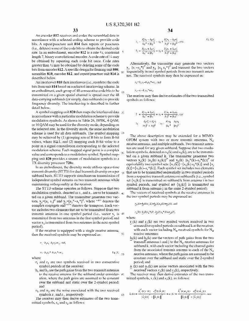
US 8,320,301 B2 33
An encoder 812 receives and codes the scrambled data in accordance with a selected coding scheme to provide code bits. A repeat/puncture unit 814 then repeats or punctures (i.e., deletes) some of the code bits to obtain the desired code rate. In an embodiment, encoder 812 is a rate /2, constraint length 7, binary convolutional encoder. A code rate of/4 may be obtained by repeating each code bit once. Code rates greater than /2 may be obtained by deleting some of the code bits from encoder 812. A specific design for framing unit 808, scrambler 810, encoder 812, and repeat/puncture unit 814 is described below. An interleaver 818 then interleaves (i.e., reorders) the code
bits from unit 814 based on a selected interleaving scheme. In an embodiment, each group of 48 consecutive code bits to be transmitted on a given spatial channel is spread over the 48 data-carrying Subbands (or simply, data Subbands) to provide frequency diversity. The interleaving is described in further detail below. A symbol mapping unit 820 then maps the interleaved data
in accordance with a particular modulation scheme to provide modulation symbols. As shown in Table 26, BPSK, 4 QAM, or 16 QAM may be used for the diversity mode, depending on the selected rate. In the diversity mode, the same modulation scheme is used for all data Subbands. The symbol mapping may be achieved by (1) grouping sets of B bits to form B-bit values, where B21, and (2) mapping each B-bit value to a point in a signal constellation corresponding to the selected modulation scheme. Each mapped signal point is a complex value and corresponds to a modulation symbol. Symbol map ping unit 820 provides a stream of modulation symbols to a TX diversity processor 720a.
In an embodiment, the diversity mode utilizes space-time transmit diversity (STTD) for dual transmit diversity on a per subband basis. STTD supports simultaneous transmission of independent symbol streams on two transmit antennas while maintaining orthogonality at the receiver. The STTD scheme operates as follows. Suppose that two
modulation symbols, denoted as Sands, are to be transmit ted on a given Subband. The transmitter generates two vec tors, x=ss, and x=s*-s *, where “*” denotes the complex conjugate and “” denotes the transpose. Each vec tor includes two elements that are to be transmitted from two transmit antennas in one symbol period (i.e., vector X is transmitted from two antennas in the first symbol period, and vector X is transmitted from two antennas in the next symbol period).
If the receiver is equipped with a single receive antenna, then the received symbols may be expressed as:
where r and r are two symbols received in two consecutive
symbol periods at the receiver; handh are the path gains from the two transmit antennas
to the receive antenna for the Subband under consider ation, where the path gains are assumed to be constant over the subband and static over the 2-symbol period; and
in and n are the noise associated with the two received symbols r and r, respectively.
The receiver may then derive estimates of the two trans mitted symbols, S and S as follows:
10
15
25
30
35
40
45
50
55
60
65
hiri – har hin -han Eq. (2) S = = S + , , , an h1 + ha h1+h
S = hiri + hir S -- hin + hin 2 = . . . a = y2 - . . . .
Alternatively, the transmitter may generate two vectors x-s-s-I and X-Is, s, and transmit the two vectors sequentially in two symbol periods from two transmit anten nas. The received symbols may then be expressed as:
The receiver may then derive estimates of the two transmitted symbols as follows:
The above description may be extended for a MIMO OFDM system with two or more transmit antennas, N. receive antennas, and multiple Subbands. Two transmit anten nas are used for any given Subband. Suppose that two modu lation symbols, denoted as S(k) and s(k), are to be transmit ted on a given Subband k. The transmitter generates two vectors X (k)s (k) s(k) and X(k)=s*(k)-s(k) or equivalently two symbol sets {x (k)}={s1(k) s(k)} and {x, (k)}={s(k)-s(k)}. Each symbol set includes two elements that are to be transmitted sequentially in two symbol periods from a respective transmit antenna on Subband k (i.e., symbol set {x,(k) is transmitted on Subband k from antennai in two symbol periods, and symbol set {x,(k)} is transmitted on Subband k from antennai in the same 2-symbol period). The vectors of received symbols at the receive antennas in
the two symbol periods may be expressed as:
where r(k) and r(k) are two symbol vectors received in two
consecutive symbol periods on subband k at the receiver, with each vector including N received symbols for N receive antennas;
h,(k) and h(k) are the vectors of path gains from the two T transmit antennas i and j to the N receive antennas for
Subband k, with each vector including the channel gains from the associated transmit antenna to each of the N. receive antennas, where the path gains are assumed to be constant over the subband and static over the 2-symbol period; and
n(k) and n(k) are noise vectors associated with the two received vectors r(k) and r(k), respectively.
The receiver may then derive estimates of the two trans mitted symbols, s(k) and s(k), as follows:
S1(k) = , and
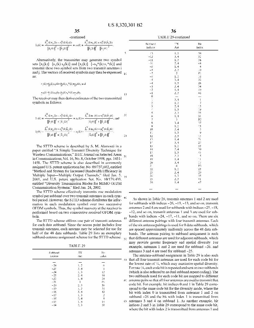
US 8,320,301 B2 35
-continued
Alternatively, the transmitter may generate two symbol sets {x,(k)}={s(k) s(k)} and {x,(k)}={-S*(k) s(k)} and transmit these two symbol sets from two transmit antennas i andj. The vectors of received symbols may then be expressed aS
The receiver may then derive estimates of the two transmitted symbols as follows:
S1(k) = , and
The STTD scheme is described by S. M. Alamouti in a paper entitled “A Simple Transmit Diversity Technique for Wireless Communications.” IEEE Journal on Selected Areas in Communications, Vol. 16, No. 8, October 1998, pgs. 1451 1458. The STTD scheme is also described in commonly assigned U.S. patent application Ser. No. 09/737,602, entitled “Method and System for Increased Bandwidth Efficiency in Multiple Input Multiple Output Channels. filed Jan. 5, 2001, and U.S. patent application Ser. No. 10/179,439, entitled “Diversity Transmission Modes for MIMO OFDM Communication Systems, filed Jun. 24, 2002. The STTD scheme effectively transmits one modulation
symbol per Subband over two transmit antennas in each sym bol period. However, the STTD scheme distributes the infor mation in each modulation symbol over two Successive OFDM symbols. Thus, the symbol recovery at the receiver is performed based on two consecutive received OFDM sym bols.
The STTD scheme utilizes one pair of transmit antennas for each data subband. Since the access point includes four transmit antennas, each antenna may be selected for use for half of the 48 data subbands. Table 29 lists an exemplary subband-antenna assignment scheme for the STTD scheme.
TABLE 29
Subband TX Bit Indices Ant Index
-26 1, 2 O -25 3, 4 6 -24 1, 3 12 -23 2, 4 18 -22 1, 4 24 -21 1 PO -20 2, 3 30 -19 1, 2 36 -18 3, 4 42 -17 1, 3 2 -16 2, 4 8 -15 1, 4 14 -14 23 2O
10
15
25
30
35
40
45
50
55
60
65
36 TABLE 29-continued
Subband TX Bit Indices Ant Index
-13 2 26 -12 3, 4 32 -11 , 3 38 -10 2, 4 44 -9 , 4 4 -8 2, 3 10 -7 2 P1 -6 2 16 -5 3, 4 22 -4 , 3 28 -3 2, 4 34 -2 , 4 40 -1 2, 3 46 O 1 3, 4 1 2 2 7 3 2, 4 13 4 , 3 19 5 2, 3 25 6 , 4 31 7 3 P2 8 3, 4 37 9 2 43 10 2, 4 3 11 , 3 9 12 2, 3 15 13 , 4 21 14 3, 4 27 15 2 33 16 2, 4 39 17 , 3 45 18 2,3 5 19 , 4 11 2O 3, 4 17 21 4 P3 22 2 23 23 2, 4 29 24 , 3 35 25 2, 3 41 26 , 4 47
As shown in Table 29, transmit antennas 1 and 2 are used for subbands with indices -26, -19, -13, and so on, transmit antennas 2 and 4 are used for Subbands with indices -25, -18, -12, and so on, transmit antennas 1 and 3 are used for Sub bands with indices -24, -17, -11, and so on. There are six different antenna pairings with four transmit antennas. Each of the six antenna pairings is used for 8 data Subbands, which are spaced approximately uniformly across the 48 data Sub bands. The antenna pairing to Subband assignment is such that different antennas are used for adjacent subbands, which may provide greater frequency and spatial diversity. For example, antennas 1 and 2 are used for Subband -26, and antennas 3 and 4 are used for Subband -25. The antenna-Subband assignment in Table 29 is also such
that all four transmit antennas are used for each code bit for the lowest rate of/4, which may maximize spatial diversity. For rate/4, each codebit is repeated and sent on two subbands (which is also referred to as dual subband repeat coding). The two subbands used for each code bit are mapped to different antenna pairs so that all four antennas are used to transmit that code bit. For example, bit indices 0 and 1 in Table 29 corre spond to the same code bit for the diversity mode, where the bit with index 0 is transmitted from antennas 1 and 2 on subband -26 and the bit with index 1 is transmitted from antennas 3 and 4 on Subband 1. As another example, bit indices 2 and 3 in Table 29 correspond to the same code bit, where the bit with index 2 is transmitted from antennas 1 and
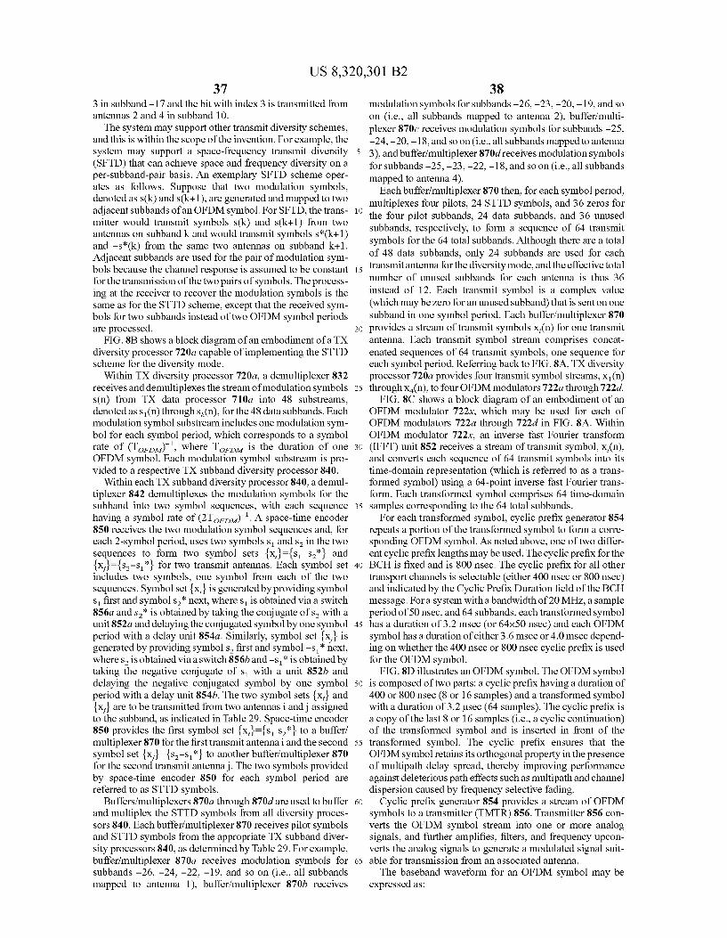
US 8,320,301 B2 37
3 in Subband -17 and the bit with index 3 is transmitted from antennas 2 and 4 in subband 10. The system may support other transmit diversity Schemes,
and this is within the scope of the invention. For example, the system may support a space-frequency transmit diversity (SFTD) that can achieve space and frequency diversity on a per-subband-pair basis. An exemplary SFTD scheme oper ates as follows. Suppose that two modulation symbols, denoted as S(k) and S(k+1), are generated and mapped to two adjacent subbands of an OFDM symbol. For SFTD, the trans mitter would transmit symbols s(k) and s(k+1) from two antennas on subband k and would transmit symbols s(k+1) and -s (k) from the same two antennas on Subband k+1. Adjacent Subbands are used for the pair of modulation sym bols because the channel response is assumed to be constant for the transmission of the two pairs of symbols. The process ing at the receiver to recover the modulation symbols is the same as for the STTD scheme, except that the received sym bols for two subbands instead of two OFDM symbol periods are processed.
FIG. 8B shows a block diagram of an embodiment of a TX diversity processor 720a capable of implementing the STTD scheme for the diversity mode.
Within TX diversity processor 720a, a demultiplexer 832 receives and demultiplexes the stream of modulation symbols s(n) from TX data processor 710a into 48 substreams, denoted as S (n) through s(n), for the 48 data Subbands. Each modulation symbol Substream includes one modulation sym bol for each symbol period, which corresponds to a symbol rate of (Toro)", where Toro is the duration of one OFDM symbol. Each modulation symbol substream is pro vided to a respective TX subband diversity processor 840.
Within each TX subband diversity processor 840, a demul tiplexer 842 demultiplexes the modulation symbols for the Subband into two symbol sequences, with each sequence having a symbol rate of (2Toro). A space-time encoder 850 receives the two modulation symbol sequences and, for each 2-symbol period, uses two symbols Sands in the two sequences to form two symbol sets {x}={s S*} and {x}={s-S*} for two transmit antennas. Each symbol set includes two symbols, one symbol from each of the two sequences. Symbol set {x} is generated by providing symbol s first and symbols next, where S is obtained via a Switch 856a and s is obtained by taking the conjugate of s with a unit 852a and delaying the conjugated symbol by one symbol period with a delay unit 854a. Similarly, symbol set {x} is generated by providing symbols first and symbol -s next, where s is obtained via a switch 856b and -s is obtained by taking the negative conjugate of s with a unit 852b and delaying the negative conjugated symbol by one symbol period with a delay unit 854b. The two symbol sets {x} and {x} are to be transmitted from two antennas i and jassigned to the subband, as indicated in Table 29. Space-time encoder 850 provides the first symbol set {x,}={ss to a buffer? multiplexer 870 for the first transmit antennai and the second symbol set {x}={s-s, *} to another buffer/multiplexer 870 for the second transmit antennaj. The two symbols provided by space-time encoder 850 for each symbol period are referred to as STTD symbols.
Buffers/multiplexers 870a through 870d are used to buffer and multiplex the STTD symbols from all diversity proces sors 840. Each buffer/multiplexer 870 receives pilot symbols and STTD symbols from the appropriate TX subband diver sity processors 840, as determined by Table 29. For example, buffer/multiplexer 870a receives modulation symbols for Subbands -26, -24, -22, -19, and so on (i.e., all Subbands mapped to antenna 1), buffer/multiplexer 870b receives
10
15
25
30
35
40
45
50
55
60
65
38 modulation symbols for subbands-26, -23, -20, -19, and so on (i.e., all Subbands mapped to antenna 2), buffer/multi plexer 870c receives modulation symbols for subbands -25, -24, -20, -18, and so on (i.e., all Subbands mapped to antenna 3), and buffer? multiplexer 870d receives modulation symbols for subbands -25, -23, -22, -18, and so on (i.e., all subbands mapped to antenna 4).
Each buffer/multiplexer 870 then, for each symbol period, multiplexes four pilots, 24 STTD symbols, and 36 Zeros for the four pilot subbands, 24 data subbands, and 36 unused Subbands, respectively, to form a sequence of 64 transmit symbols for the 64 total subbands. Although there are a total of 48 data subbands, only 24 Subbands are used for each transmit antenna for the diversity mode, and the effective total number of unused subbands for each antenna is thus 36 instead of 12. Each transmit symbol is a complex value (which may be Zero for an unused Subband) that is sent on one subband in one symbol period. Each buffer/multiplexer 870 provides a stream of transmit symbols X,(n) for one transmit antenna. Each transmit symbol stream comprises concat enated sequences of 64 transmit symbols, one sequence for each symbol period. Referring back to FIG. 8A, TX diversity processor 720a provides four transmit symbol streams, X(n) through X(n), to four OFDM modulators 722a through 722d.
FIG. 8C shows a block diagram of an embodiment of an OFDM modulator 722.x, which may be used for each of OFDM modulators 722a through 722d in FIG. 8A. Within OFDM modulator 722.x, an inverse fast Fourier transform (IFFT) unit 852 receives a stream of transmit symbol, x, (n), and converts each sequence of 64 transmit symbols into its time-domain representation (which is referred to as a trans formed symbol) using a 64-point inverse fast Fourier trans form. Each transformed symbol comprises 64 time-domain samples corresponding to the 64 total Subbands.
For each transformed symbol, cyclic prefix generator 854 repeats a portion of the transformed symbol to form a corre sponding OFDM symbol. As noted above, one of two differ ent cyclic prefix lengths may be used. The cyclic prefix for the BCH is fixed and is 800 nsec. The cyclic prefix for all other transport channels is selectable (either 400 nsec or 800 nsec) and indicated by the Cyclic Prefix Duration field of the BCH message. For a system with a bandwidth of 20 MHz, a sample period of 50 nsec, and 64 subbands, each transformed symbol has a duration of 3.2 msec (or 64x50 nsec) and each OFDM symbol has a duration of either 3.6 msec or 4.0 msec depend ing on whether the 400 nsec or 800 nsec cyclic prefix is used for the OFDM symbol. FIG.8D illustrates an OFDM symbol. The OFDM symbol
is composed of two parts: a cyclic prefix having a duration of 400 or 800 nsec (8 or 16 samples) and a transformed symbol with a duration of 3.2 usec (64 samples). The cyclic prefix is a copy of the last 8 or 16 samples (i.e., a cyclic continuation) of the transformed symbol and is inserted in front of the transformed symbol. The cyclic prefix ensures that the OFDM symbol retains its orthogonal property in the presence of multipath delay spread, thereby improving performance against deleterious path effects such as multipath and channel dispersion caused by frequency selective fading.
Cyclic prefix generator 854 provides a stream of OFDM symbols to a transmitter (TMTR) 856. Transmitter 856 con verts the OFDM symbol stream into one or more analog signals, and further amplifies, filters, and frequency upcon verts the analog signals to generate a modulated signal Suit able for transmission from an associated antenna. The baseband waveform for an OFDM symbol may be
expressed as:
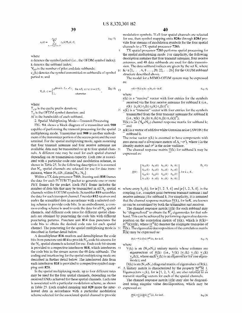
US 8,320,301 B2
where in denotes the symbol period (i.e., the OFDM symbol index): k denotes the Subband index; Ns is the number of pilot and data Subbands: c(k) denotes the symbol transmitted on Subband k of symbol period n, and
ejik AitcPs), for nT sit s (n + 1)T Eq. (4) '' (k, t) = { O, otherwise
where T is the cyclic prefix duration; Ts is the OFDM symbol duration; and Afis the bandwidth of each subband.
2. Spatial Multiplexing Mode Transmit Processing FIG. 9A shows a block diagram of a transmitter unit 900
capable of performing the transmit processing for the spatial multiplexing mode. Transmitter unit 900 is another embodi ment of the transmitter portion of the access point and the user terminal. For the spatial multiplexing mode, again assuming that four transmit antennas and four receive antennas are available, data may be transmitted on up to four spatial chan nels. A different rate may be used for each spatial channel depending on its transmission capacity. Each rate is associ ated with a particular code rate and modulation scheme, as shown in Table 25. In the following description it is assumed that N. spatial channels are selected for use for data trans mission, where NisNssmin{N, N}.
Within a TX data processor 710b, framing unit 808 frames the data for each FCH/RCH packet to generate one or more PHY frames for the packet. Each PHY frame includes the number of data bits that may be transmitted in all N. spatial channels within 6 OFDM symbols. Scrambler 810 scrambles the data for each transport channel. Encoder 812 receives and codes the Scrambled data in accordance with a selected cod ing scheme to provide code bits. In an embodiment, a com mon coding scheme is used to code the data for all N. spatial channels, and different code rates for different spatial chan nels are obtained by puncturing the code bits with different puncturing patterns. Puncture unit 814 thus punctures the code bits to obtain the desired code rate for each spatial channel. The puncturing for the spatial multiplexing mode is described in further detail below. A demultiplexer 816 receives and demultiplexes the code
bits from puncture unit 814 to provide Nicode bit streams for the Nespatial channels selected for use. Each code bit stream is provided to a respective interleaver 818, which interleaves the code bits in the stream across the 48 data subbands. The coding and interleaving for the spatial multiplexing mode are described in further detail below. The interleaved data from each interleaver 818 is provided to a respective symbol map ping unit 820.
In the spatial multiplexing mode, up to four different rates may be used for the four spatial channels, depending on the received SNRs achieved for these spatial channels. Each rate is associated with a particular modulation scheme, as shown in Table 25. Each symbol mapping unit 820 maps the inter leaved data in accordance with a particular modulation scheme selected for the associated spatial channel to provide
10
15
25
30
35
40
45
50
55
60
65
40 modulation symbols. If all four spatial channels are selected for use, then symbol mapping units 820a through 820d pro vide four streams of modulation symbols for the four spatial channels to a TX spatial processor 720b. TX spatial processor 720b performs spatial processing for
the spatial multiplexing mode. For simplicity, the following description assumes that four transmit antennas, four receive antennas, and 48 data Subbands are used for data transmis sion. The data subband indices are given by the set K, where K={1,..., 6, 8..., 20, 22, ... 26 for the OFDM subband structure described above. The model for a MIMO-OFDM system may be expressed
aS
r(k)-H(k)xck)+n(k), for ke K, Eq. (5) where r(k) is a “receive” vector with four entries for the symbols
received via the four receive antennas for subband k (i.e., r(k)-Ir(k) r(k) r(k) ra(k));
X(k) is a “transmit vector with four entries for the symbols T transmitted from the four transmit antennas for subband k
(i.e., x(k)-X1(k) X2(k) X(k) X1(k)); H(k) is an (NXN) channel response matrix for Subband k: and
n(k) is a vector of additive white Gaussian noise (AWGN) for T subband k. The noise vector n(k) is assumed to have components with zero mean and a covariance matrix of AOI, where I is the identity matrix and of is the noise variance. The channel response matrix H(k) for subband k may be
expressed as:
h1(k) h. (k H(k) = 2.1(k) h3.1(k)
h1.3(k) h2.3 (k) h3.3(k) h4.3 (k)
hoa (k 2.4(k) , for ke K,
Eq. (6)
where entry h(k), for ie {1, 2, 3, 4} and je{1,2,3,4}, is the coupling (i.e., complex gain) between transmit antennai and receive antennai for Subband k. For simplicity, it is assumed that the channel response matrices H(k), for keK, are known or can be ascertained by both the transmitter and receiver. The channel response matrix H(k) for each subband may
be "diagonalized to obtain the Neigenmodes for that sub band. This can be achieved by performing eigenvalue decom position on the correlation matrix of H(k), which is R(k)= H'(k)H(k), where H'(k) denotes the conjugate transpose of H(k). The eigenvalue decomposition of the correlation matrix R(k) may be expressed as:
R(k)=P(k)D(k)r"(k), for ke K, Eq. (7) where
V(k) is an (NXN) unitary matrix whose columns are eigenvectors of R(k) (i.e., V(k)-v(k) V(k) V(k) V(k), where each v,(k) is an eigenvector for one eigen mode); and
D(k) is an (NXN) diagonal matrix of eigenvalues of R(k). A unitary matrix is characterized by the property MM-I. Eigenvectors v,(k), for ie {1, 2, 3, 4}, are also referred to as transmit steering vectors for each of the spatial channels. The channel response matrix H(k) may also be diagonal
ized using singular value decomposition, which may be expressed as:
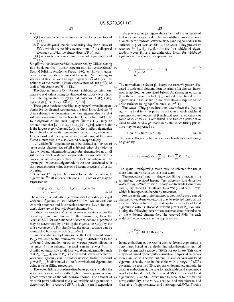
US 8,320,301 B2 41
where V(k) is a matrix whose columns are right eigenvectors of
H(k); X(k) is a diagonal matrix containing singular values of
H(k), which are positive square roots of the diagonal elements of D(k), the eigenvalues of R(k); and
U(k) is a matrix whose columns are left eigenvectors of H(k).
Singular value decomposition is described by Gilbert Strang in a book entitled “Linear Algebra and Its Applications.” Second Edition, Academic Press, 1980. As shown in equa tions (7) and (8), the columns of the matrix V(k) are eigen vectors of R(k) as well as right eigenvectors of H(k). The columns of the matrix U(k) are eigenvectors of H(k)H'(k) as well as left eigenvectors of H(k).
The diagonal matrix D(k) for each subband contains non negative real values along the diagonal and Zeros everywhere else. The eigenvalues of R(k) are denoted as { (k), W2(k),
(k), W(k) or {,(k) for ie {1, 2, 3, 4}. The eigenvalue decomposition may be performed indepen
dently for the channel response matrix H(k) for each of the 48 data subbands to determine the four eigenmodes for that subband (assuming that each matrix H(k) is full rank). The four eigenvalues for each diagonal matrix D(k) may be ordered such that w(k)2·2(k)ews (k)e^a(k), where w(k) is the largest eigenvalue and W(k) is the Smallest eigenvalue for subband k. When the eigenvalues for each diagonal matrix D(k) are ordered, the eigenvectors (or columns) of the asso ciated matrix V(k) are also ordered correspondingly. A “wideband' eigenmode may be defined as the set of
same-order eigenmodes of all Subbands after the ordering (i.e., wideband eigenmode m includes eigenmodes m of all Subbands). Each wideband eigenmode is associated with a respective set of eigenvectors for all of the subbands. The “principal wideband eigenmode is the one associated with the largest singular value in each of the matrices S(k) after the ordering. A vector d" may then be formed to include the m-th rank
eigenvalue for all 48 data subbands. This vector d" may be expressed as:
d"-(2,(-26)... (-22). . . .(22). . . .(26), for
The vectord" includes the eigenvalues for the bestorprincipal wideband eigenmode. For a MIMO-OFDM system with four transmit antennas and four receive antennas (i.e., a 4x4 sys tem), there are up four wideband eigenmodes.
If the noise variance of at the receiver is constant across the operating band and known to the transmitter, then the received SNR for each subband of each wideband eigenmode may be determined by dividing the eigenvalue w(k) by the noise variance of. For simplicity, the noise variance can be assumed to be equal to one (i.e., of–1).
For the spatial multiplexing mode, the total transmit power P. available to the transmitter may be distributed to the wideband eigenmodes based on various power allocation schemes. In one scheme, the total transmit power P is distributed uniformly to all four wideband eigenmodes such that PP/4, where P is the transmit power allocated to wideband eigenmodem. In another scheme, the total transmit power P is distributed to the four wideband eigenmodes using a water-filling procedure.
The water-filling procedure distributes power such that the wideband eigenmodes with higher power gains receive greater fractions of the total transmit power. The amount of transmit power allocated to a given wideband eigenmode is determined by its received SNR, which in turn is dependent
5
10
15
25
30
35
40
45
50
55
60
65
42 on the power gains (or eigenvalues) for all of the Subbands of that wideband eigenmode. The water-filling procedure may allocate Zero transmit power to wideband eigenmodes with sufficiently poor received SNRs. The water-filling procedure receives f=f3, 32, ?s, f for the four wideband eigen modes, where f3, is a normalization factor for wideband eigenmodem and may be expressed as:
1 Eq. (10) f3 = , for n = {1, 2, 3, 4}.
XA, (k)
The normalization factor B, keeps the transmit power allo cated to wideband eigenmodem invariant after channel inver sion is applied, as described below. As shown in equation (10), the normalization factor B can be derived based on the eigenvalues in the vector d" and with the assumption of the noise variance being equal to one (i.e., of-1). The water-filling procedure then determines the fraction
C, of the total transmit power to allocate to each wideband eigenmode based on the set B Such that spectral efficiency or some other criterion is optimized. The transmit power allo cated to wideband eigenmode m by the water-filling proce dure may be expressed as:
P=C.P. for m={1,2,3,4}. Eq. (11)
The power allocations for the four wideband eigenmodes may be given by
4.
On = 1 and X P = Potat. Q = a1, a2, a3, a 4}, where 2. The spatial multiplexing mode may be selected for use if more than one value in set C. is non-zero. The procedure for performing water-filling is known in the
art and not described herein. One reference that describes water-filling is “Information Theory and Reliable Communi cation.” by Robert G. Gallager, John Wiley and Sons, 1968, which is incorporated herein by reference.
For the spatial multiplexing mode, the rate for each spatial channel or wideband eigenmode may be selected based on the received SNR achieved by that spatial channel/wideband eigenmode with its allocated transmit power of P. For sim plicity, the following description assumes data transmission on the wideband eigenmodes. The received SNR for each wideband eigenmode may be expressed as:
Pinfin C-2
Eq. (12) yn F for n = {1, 2, 3, 4}.
In one embodiment, the rate for each wideband eigenmode is determined based on a table that includes the rates supported by the system and a range of SNRs for each rate. This table may be obtained by computer simulation, empirical measure ments, and so on. The particular rate to use for each wideband eigenmode is the rate in the table with a range of SNRs covering the received SNR for the wideband eigenmode. In another embodiment, the rate for each wideband eigenmode is selected based on (1) the received SNR for the wideband eigenmode, (2) an SNR offset used to account for estimation error, variability in the MIMO channel, and other factors, and (3) a table of supported rates and their required SNRs. For this
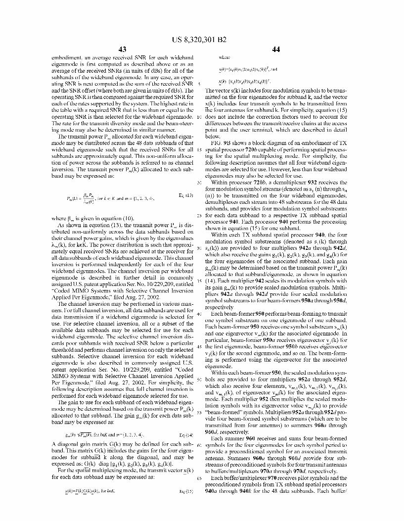
US 8,320,301 B2 43
embodiment, an average received SNR for each wideband eigenmode is first computed as described above or as an average of the received SNRs (in units of dBs) for all of the Subbands of the wideband eigenmode. In any case, an oper ating SNR is next computed as the sum of the received SNR and the SNR offset (where both are given in units of dBs). The operating SNR is then compared against the required SNR for each of the rates supported by the system. The highest rate in the table with a required SNR that is less than or equal to the operating SNR is then selected for the wideband eigenmode. The rate for the transmit diversity mode and the beam-steer ing mode may also be determined in similar manner. The transmit power P, allocated for each wideband eigen
mode may be distributed across the 48 data subbands of that wideband eigenmode such that the received SNRs for all Subbands are approximately equal. This non-uniform alloca tion of power across the subbands is referred to as channel inversion. The transmit power P(k) allocated to each sub band may be expressed as:
fin Pin (k)
P(k) = Eq (13) , for k e K and m = {1, 2, 3, 4},
where f3, is given in equation (10). As shown in equation (13), the transmit power P, is dis
tributed non-uniformly across the data subbands based on their channel power gains, which is given by the eigenvalues w(k), for keK. The power distribution is such that approxi mately equal received SNRs are achieved at the receiver for all data subbands of each wideband eigenmode. This channel inversion is performed independently for each of the four wideband eigenmodes. The channel inversion per wideband eigenmode is described in further detail in commonly assigned U.S. patent application Ser. No. 10/229.209, entitled “Coded MIMO Systems with Selective Channel Inversion Applied Per Eigenmode filed Aug. 27, 2002. The channel inversion may be performed in various man
ners. For full channel inversion, all data subbands are used for data transmission if a wideband eigenmode is selected for use. For selective channel inversion, all or a subset of the available data subbands may be selected for use for each wideband eigenmode. The selective channel inversion dis cards poor subbands with received SNR below a particular threshold and performs channel inversion on only the selected subbands. Selective channel inversion for each wideband eigenmode is also described in commonly assigned U.S. patent application Ser. No. 10/229,209, entitled “Coded MIMO Systems with Selective Channel Inversion Applied Per Eigenmode.” filed Aug. 27, 2002. For simplicity, the following description assumes that full channel inversion is performed for each wideband eigenmode selected for use. The gain to use for each Subband of each wideband eigen
mode may be determined based on the transmit power P(k) allocated to that Subband. The gain g(k) for each data Sub band may be expressed as:
A diagonal gain matrix G(k) may be defined for each Sub band. This matrix G(k) includes the gains for the four eigen modes for Subband k along the diagonal, and may be expressed as: G(k)=diagg (k), g(k), g(k), ga(k).
For the spatial multiplexing mode, the transmit vector x(k) for each data Subband may be expressed as:
Eq. (14)
10
15
25
30
35
40
45
50
55
60
65
44 where
s(k)-s(k)s2(k)ss(k)s (k), and
The vector s(k) includes four modulation symbols to be trans mitted on the four eigenmodes for subband k, and the vector X(k) includes four transmit symbols to be transmitted from the four antennas for Subband k. For simplicity, equation (15) does not include the correction factors used to account for differences between the transmit/receive chains at the access point and the user terminal, which are described in detail below. FIG.9B shows a block diagram of an embodiment of TX
spatial processor 720b capable of performing spatial process ing for the spatial multiplexing mode. For simplicity, the following description assumes that all four wideband eigen modes are selected for use. However, less than four wideband eigenmodes may also be selected for use.
Within processor 720b, a demultiplexer 932 receives the four modulation symbol streams (denoted as S (n) throughs (n)) to be transmitted on the four wideband eigenmodes, demultiplexes each stream into 48 substreams for the 48 data Subbands, and provides four modulation symbol Substreams for each data subband to a respective TX subband spatial processor 940. Each processor 940 performs the processing shown in equation (15) for one subband.
Within each TX Subband spatial processor 940, the four modulation symbol Substreams (denoted as S(k) through sa(k)) are provided to four multipliers 942a through 942d, which also receive the gains g(k), g2(k), ga(k), and ga(k) for the four eigenmodes of the associated subband. Each gain g(k) may be determined based on the transmit power P(k) allocated to that Subband/eigenmode, as shown in equation (14). Each multiplier 942 scales its modulation symbols with its gain g(k) to provide scaled modulation symbols. Multi pliers 942a through 942d provide four scaled modulation symbol substreams to four beam-formers 950a through950d. respectively.
Each beam-former 950 performs beam-forming to transmit one symbol Substream on one eigenmode of one Subband. Each beam-former 950 receives one symbol substreams,(k) and one eigenvector V(k) for the associated eigenmode. In particular, beam-former 950a receives eigenvector v(k) for the first eigenmode, beam-former 950b receives eigenvector V(k) for the second eigenmode, and so on. The beam-form ing is performed using the eigenvector for the associated eigenmode.
Within each beam-former 950, the scaled modulation sym bols are provided to four multipliers 952a through 952d. which also receive four elements, V, (k), V,2(k), Vas (k), and V.(k), of eigenvector V,(k) for the associated eigen mode. Each multiplier 952 then multiplies the scaled modu lation symbols with its eigenvector value V, (k) to provide “beam-formed” symbols. Multipliers 952a through952d pro vide four beam-formed symbol substreams (which are to be transmitted from four antennas) to summers 960a through 960d, respectively.
Each summer 960 receives and sums four beam-formed symbols for the four eigenmodes for each symbol period to provide a preconditioned symbol for an associated transmit antenna. Summers 960a through 960d provide four sub streams of preconditioned symbols for four transmit antennas to buffers/multiplexers 970a through970d, respectively.
Each buffer/multiplexer 970 receives pilot symbols and the preconditioned symbols from TX subband spatial processors 94.0a through 940k for the 48 data subbands. Each buffer?
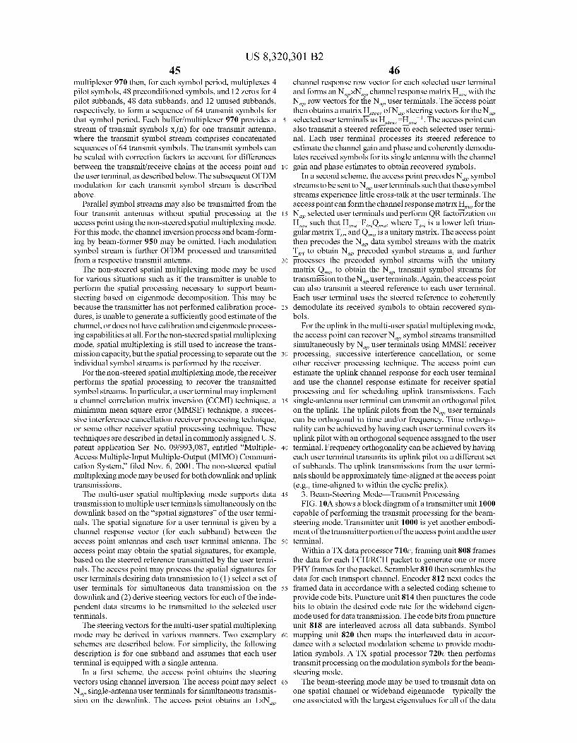
US 8,320,301 B2 45
multiplexer 970 then, for each symbol period, multiplexes 4 pilot symbols, 48 preconditioned symbols, and 12 Zeros for 4 pilot subbands, 48 data subbands, and 12 unused subbands, respectively, to form a sequence of 64 transmit symbols for that symbol period. Each buffer/multiplexer 970 provides a stream of transmit symbols X,(n) for one transmit antenna, where the transmit symbol stream comprises concatenated sequences of 64 transmit symbols. The transmit symbols can be scaled with correction factors to account for differences between the transmit/receive chains at the access point and the user terminal, as described below. The subsequent OFDM modulation for each transmit symbol stream is described above.
Parallel symbol streams may also be transmitted from the four transmit antennas without spatial processing at the access point using the non-steered spatial multiplexing mode. For this mode, the channel inversion process and beam-form ing by beam-former 950 may be omitted. Each modulation symbol stream is further OFDM processed and transmitted from a respective transmit antenna. The non-steered spatial multiplexing mode may be used
for various situations such as if the transmitter is unable to perform the spatial processing necessary to Support beam steering based on eigenmode decomposition. This may be because the transmitter has not performed calibration proce dures, is unable to generate a Sufficiently good estimate of the channel, or does not have calibration and eigenmode process ing capabilities at all. For the non-steered spatial multiplexing mode, spatial multiplexing is still used to increase the trans mission capacity, but the spatial processing to separate out the individual symbol streams is performed by the receiver.
For the non-steered spatial multiplexing mode, the receiver performs the spatial processing to recover the transmitted symbol streams. In particular, a user terminal may implement a channel correlation matrix inversion (CCMI) technique, a minimum mean square error (MMSE) technique, a Succes sive interference cancellation receiver processing technique, or some other receiver spatial processing technique. These techniques are described in detail in commonly assigned U.S. patent application Ser. No. 09/993,087, entitled “Multiple Access Multiple-Input Multiple-Output (MIMO) Communi cation System.” filed Nov. 6, 2001. The non-steered spatial multiplexing mode may be used for both downlink and uplink transmissions.
The multi-user spatial multiplexing mode Supports data transmission to multiple user terminals simultaneously on the downlink based on the “spatial signatures” of the user termi nals. The spatial signature for a user terminal is given by a channel response vector (for each subband) between the access point antennas and each user terminal antenna. The access point may obtain the spatial signatures, for example, based on the steered reference transmitted by the user termi nals. The access point may process the spatial signatures for user terminals desiring data transmission to (1) select a set of user terminals for simultaneous data transmission on the downlink and (2) derive steering vectors for each of the inde pendent data streams to be transmitted to the selected user terminals.
The steering vectors for the multi-user spatial multiplexing mode may be derived in various manners. Two exemplary schemes are described below. For simplicity, the following description is for one Subband and assumes that each user terminal is equipped with a single antenna.
In a first scheme, the access point obtains the steering vectors using channel inversion. The access point may select N. single-antenna user terminals for simultaneous transmis sion on the downlink. The access point obtains an 1xN,
10
15
25
30
35
40
45
50
55
60
65
46 channel response row vector for each selected user terminal and forms an NXN channel response matrix H, with the N. row vectors for the N user terminals. The access point then obtains a matrix H of N, steering vectors for the N. selected user terminals as H. H.'. The access point can also transmit a steered reference to each selected user termi nal. Each user terminal processes its steered reference to estimate the channel gain and phase and coherently demodu lates received symbols for its single antenna with the channel gain and phase estimates to obtain recovered symbols.
In a second scheme, the access point precodes N. symbol streams to be sent to N user terminals such that these symbol streams experience little cross-talk at the user terminals. The access point can form the channel response matrix H for the N selected user terminals and perform QR factorization on H. Such that H. F.O., where T is a lower left trian gular matrix T and Q, is a unitary matrix. The access point then precodes the N data symbol streams with the matrix T, to obtain N precoded symbol streams a, and further processes the precoded symbol streams with the unitary matrix Q, to obtain the N transmit symbol streams for transmission to the N user terminals. Again, the access point can also transmit a steered reference to each user terminal. Each user terminal uses the steered reference to coherently demodulate its received symbols to obtain recovered sym bols.
For the uplink in the multi-user spatial multiplexing mode, the access point can recover N. symbol streams transmitted simultaneously by N user terminals using MMSE receiver processing, successive interference cancellation, or some other receiver processing technique. The access point can estimate the uplink channel response for each user terminal and use the channel response estimate for receiver spatial processing and for scheduling uplink transmissions. Each single-antenna user terminal can transmit an orthogonal pilot on the uplink. The uplink pilots from the N user terminals can be orthogonal in time and/or frequency. Time orthogo nality can be achieved by having each user terminal covers its uplink pilot with an orthogonal sequence assigned to the user terminal. Frequency orthogonality can beachieved by having each user terminal transmits its uplink pilot on a different set of subbands. The uplink transmissions from the user termi nals should be approximately time-aligned at the access point (e.g., time-aligned to within the cyclic prefix).
3. Beam-Steering Mode Transmit Processing FIG. 10A shows a block diagram of a transmitter unit 1000
capable of performing the transmit processing for the beam steering mode. Transmitter unit 1000 is yet another embodi ment of the transmitter portion of the access point and the user terminal.
Within a TX data processor 710c, framing unit 808 frames the data for each FCH/RCH packet to generate one or more PHY frames for the packet. Scrambler 810 then scrambles the data for each transport channel. Encoder 812 next codes the framed data in accordance with a selected coding scheme to provide code bits. Puncture unit 814 then punctures the code bits to obtain the desired code rate for the wideband eigen mode used for data transmission. The code bits from puncture unit 818 are interleaved across all data subbands. Symbol mapping unit 820 then maps the interleaved data in accor dance with a selected modulation scheme to provide modu lation symbols. ATX spatial processor 720c then performs transmit processing on the modulation symbols for the beam steering mode. The beam-steering mode may be used to transmit data on
one spatial channel or wideband eigenmode—typically the one associated with the largest eigenvalues for all of the data
US 8,320,301 B2 47
subbands. The beam-steering mode may be selected if the transmit power allocation to the wideband eigenmodes results in only one entry in the set a being non-zero. Whereas the spatial multiplexing mode performs beam-forming for each of the selected eigenmodes of each subband based on its eigenvector, the beam-steering mode performs beam-steering based on a “normalized eigenvector for the principal eigen mode of each Subband to transmit data on that single eigen mode. The four elements of each eigenvector V (k), for keK, for
the principal eigenmode may have different magnitudes. The four preconditioned symbols obtained based on the four ele ments of eigenvector V (k) for each Subband may then have different magnitudes. Consequently, the four per-antenna transmit vectors, each of which includes the preconditioned symbols for all data Subbands for a given transmit antenna, may have different magnitudes. If the transmit powerfor each transmit antenna is limited (e.g., because of limitations of the power amplifiers), then the beam-forming technique may not fully use the total power available for each antenna. The beam-steering mode uses only the phase information
from eigenvectors V (k), forkeK, for the principal eigenmode and normalizes each eigenvector Such that all four elements in the eigenvector have equal magnitudes. The normalized eigenvector V(k) for Subband k may be expressed as:
(k)-Ae 184e 6284e 63.84eek', Eq. (16) where A is a constant (e.g., A-1); and 0,(k) is the phase for subband k of transmitantennai, which
is given as:
Eq. (17) 6; (k) = 1 V1(k) = tan (EHE }
As shown in equation (17), the phase of each element in the vector V(k) is obtained from the corresponding element of eigenvector V (k) (i.e., 0,(k) is obtained from VI,(k), where v(k)-v, (k) V12(k) V1(k) V(k)).
Channel inversion may also be performed for the beam steering mode so that a common rate can be used for all data subbands. The transmit power P(k) allocated to each data Subband for the beam-steering mode may be expressed as:
p, P. (k)
W Eq. (18) P(k) = , for ke K,
where is a normalization factor that keeps the total transmit power invariant after channel inversion is applied;
P, is the transmit power allocated to each of the four anten nas; and
w(k) is the power gain for Subband k of the principal eigenmode for the beam-steering mode.
The normalization factor f3 may be expressed as:
1 Eq. (19)
XA,"(k) kek
B =
10
15
25
30
35
40
45
50
55
60
65
48 The transmit power P, may be given as Pi—P/4 (i.e., uni form allocation of the total transmit power across the four transmit antennas). The power gain w(k) may be expressed aS
The channel inversion results in power allocation of P(k), for keK, for the 48 data subbands. The gain for each data Subband may then be given as g(k)-VP,(k).
For the beam-steering mode, the transmit vector X(k) for each Subband may be expressed as:
Again for simplicity, equation (21) does not include the cor rection factors used to account for differences between the transmit/receive chains at the access point and the user ter minal. As shown in equation (16), the four elements of the nor
malized steering vector V(k) for each subband have equal magnitude but possibly different phases. The beam-steering thus generates one transmit vector X(k) for each Subband, with the four elements of X(k) having the same magnitudebut possibly different phases.
FIG. 10B shows a block diagram of an embodiment of TX spatial processor 720c capable of performing the spatial pro cessing for the beam-steering mode.
Within processor 720c, a demultiplexer 1032 receives and demultiplexes the modulation symbol stream s(n) into 48 substreams for the 48 data subbands (denoted as s(1) through s(k)). Each symbol substream is provided to a respective TX Subband beam-steering processor 1040. Each processor 1040 performs the processing shown in equation (14) for one Sub band.
Within each TX Subband beam-steering processor 1040. the modulation symbol substream is provided to a multiplier 1042, which also receives the gain g(k) for the associated subband. Multiplier 1042 then scales the modulation symbols with the gain g(k) to obtain scaled modulation symbols, which are then provided to a beam-steering unit 1050.
Beam-steering unit 1050 also receives the normalized eigenvector V(k) for the associated subband. Within beam steering unit 1050, the scaled modulation symbols are pro vided to four multipliers 1052a through 1052d, which also respectively receive the four elements, V (k), V(k), V(k), and V(k), of the normalized eigenvector V(k). Each multiplier 1052 multiplies its scaled modulation symbols with its nor malized eigenvector value V,(k) to provide preconditioned symbols. Multipliers 1052a through 1052d provide four pre conditioned symbol substreams to buffers/multiplexers 1070a through 1070d, respectively.
Each buffer/multiplexer 1070 receives pilot symbols and the preconditioned symbols from TX subband beam-steering processors 104.0a through 1040k for the 48 data subbands, multiplexes the pilot and preconditioned symbols and Zeros for each symbol period, and provides a stream of transmit symbols X,(n) for one transmit antenna. The Subsequent OFDM modulation for each transmit symbol stream is described above. The processing for the beam-steering mode is described in
further detail in commonly assigned U.S. patent application Ser. No. 10/228,393, entitled “Beam-Steering and Beam Forming for Wideband MIMO Systems.” filed Aug. 27, 2002. The system may also be designed to support a beam-forming mode whereby a data stream is transmitted on the principal eigenmode using the eigenvector instead of the normalized eigenvector.
US 8,320,301 B2 49
4. Framing for PHY Frames FIG. 11A shows an embodiment of framing unit 808,
which is used to frame the data for each FCH/RCH packet prior to Subsequent processing by the TX data processor. This framing function may be bypassed for messages sent on the BCH, FCCH, and RACH. The framing unit generates an integer number of PHY frames for each FCH/RCH packet, where each PHY frame spans 6 OFDM symbols for the embodiment described herein.
For the diversity and beam-steering modes, only one spa tial channel or wideband eigenmode is used for data trans mission. The rate for this mode is known, and the number of information bits that may be sent in the payload of each PHY frame may be computed. For the spatial multiplexing mode, multiple spatial channels may be used for data transmission. Since the rate of each spatial channel is known, the number of information bits that may be sent in the payload of each PHY frame for all spatial channels may be computed. As shown in FIG. 11A, the information bits (denoted as i
i is is ...) for each FCH/RCH packet are provided to a CRC generator 1102 and a multiplexer 1104 within framing unit 808. CRC generator 1102 generates a CRC value for the bits in the header (if any) and payload fields of each PHY frame and provides CRC bits to multiplexer 1104. Multiplexer 1104 receives the information bits, CRC bits, header bits, and pad bits (e.g., Zeros), and provides these bits in the proper order, as shown in FIG. 6, based on a PHY Frame Control signal. The framing function may be bypassed by providing the informa tion bits directly through multiplexer 1104. The framed or unframed bits (denoted as did did. . . . ) are provided to Scrambler 810.
5. Scrambling In an embodiment, the data bits for each transport channel
are scrambled prior to coding. The Scrambling randomizes the data so that a long sequence of all ones or all Zeros is not transmitted. This can reduce the variation in the peak to average power of the OFDM waveform. The scrambling may be omitted for one or more transport channels and may also be selectively enabled and disabled.
FIG. 11A also shows an embodiment of scrambler 810. In this embodiment, scrambler 810 implements a generator polynomial:
Other generator polynomials may also be used, and this is within the scope of the invention. As shown in FIG. 11A, scrambler 810 includes seven delay
elements 1112a through 1112g coupled in series. For each clock cycle, an adder 1114 performs modulo-2 addition of two bits stored in delay elements 1112d and 1112g and pro vides a scrambling bit to delay element 1112a. The framed/unframed bits (did did ...) are provided to
an adder 1116, which also receives scrambling bits from adder 1114. Adder 1116 performs modulo-2 addition of each bit d, with a corresponding scrambling bit to provide a scrambled bit q. Scrambler 810 provides a sequence of Scrambled bits, which is denoted as qi q2 q q. . . . . The initial state of the scrambler (i.e., the content of delay
elements 1112a through 1112g) is set to a 7-bit non-zero number at the start of each TDD frame. The three most sig nificant bits (MSBs) (i.e., delay element 1112e through 1112?) are always set to one (1) and the four least significant bits (LSBs) are set to the TDD frame counter, as indicated in the BCH message.
6. Encoding/Puncturing In an embodiment, a single base code is used to code data
prior to transmission. This base code generates code bits for
10
15
25
30
35
40
45
50
55
60
65
50 one code rate. All other coderates Supported by the system (as listed in Table 25) may be obtained by either repeating or puncturing the code bits. FIG.11B shows an embodiment of encoder812 that imple
ments the base code for the system. In this embodiment, the base code is a rate /2, constraint length 7 (K=7), convolutional code with generators of 133 and 171 (octal).
Within encoder 812, a multiplexer 1120 receives and mul tiplexes the scrambled bits and tail bits (e.g., Zeros). Encoder 812 further includes six delay elements 1122a through 1122f coupled in series. Four adders 1124a through 1124d are also coupled in series and used to implement the first generator (133). Similarly, four adders 1126a through 1126d are coupled in series and used to implement the second generator (171). The adders are further coupled to the delay elements in a manner to implement the two generators of 133 and 171, as shown in FIG. 11B. The scrambled bits are provided to the first delay element
1122a and to adders 1124a and 1126a. For each clock cycle, adders 1124a through 1124d perform modulo-2 addition of the incoming bit and four prior bits stored in delay elements 1122b, 1122c, 1122e, and 1122f to provide the first code bit for that clock cycle. Similarly, adders 1126a through 1126d perform modulo-2 addition of the incoming bit and four prior bits stored in delay elements 1122a, 1122b, 1122c, and 1122f to provide the second code bit for that clock cycle. The code bits generated by the first generator are denoted as a a as a . . . . and the code bits generated by the second generator are denoted as bb, b. b. . . . . A multiplexer 1128 then receives and multiplexes the two streams of code bits from the two generators into a single stream of code bits, which is denoted as a bab a bab . . . . For each scrambled bit q, two code bits a, and b, are generated, which results in a code rate of /2.
FIG. 11B also shows an embodiment of repeat/puncture unit 814 that can be used to generate other code rates based on the base code rate of/2. Within unit 814, the rate /2 code bits from encoder 812 are provided to a repeating unit 1132 and a puncturing unit 1134. Repeating unit 1132 repeats each rate /2 code bit once to obtain an effective code rate of 4. Punc turing unit 1134 deletes some of the rate /2 code bits based on a specific puncturing pattern to provide the desired code rate.
Table 30 lists exemplary puncturing patterns that may be used for the various code rates supported by the system. Other puncturing patterns may also be used, and this is within the Scope of the invention.
TABLE 30
Code Rate Puncturing Pattern
1.2 11 7,12 11111110111110 5.8 1110111011 2.3 1110 1116 11111011111110100111OO
13,16 O111101111110111OOOO101100 5.6 1110011001 78 11101010011001
To obtain a code rate ofk/n, puncturing unit 1134 provides in code bits for each group of 2k rate /2 code bits received from encoder 812. Thus, 2k-n code bits are deleted from each group of 2k code bits. The bits to be deleted from each group are denoted by Zeros in the puncturing pattern. For example, to obtain a code rate of 7/12, two bits are deleted from each group of 14 code bits from encoder 812, with the deleted bits being the 8” and 14" code bits in the group, as denoted by the
US 8,320,301 B2 51
puncturing pattern of “11111110111110. No puncturing is performed if the desired code rate is /2. A multiplexer 1136 receives the stream of code bits from
repeating unit 1132 and the stream of code bits from punc turing unit 1134. Multiplexer 1136 then provides the code bits from repeating unit 1132 if the desired code rate is 4 and the code bits from puncturing unit 1134 if the desired code rate is /2 or higher. Other codes and puncturing patterns besides those
described above may also be used, and this is within the scope of the invention. For example, a Turbo code, a block code, Some other codes, or any combination thereof may be used to code data. Also, different coding schemes may be used for different transport channels. For example, convolutional cod ing may be used for the common transport channels, and Turbo coding may be used for the dedicated transport chan nels.
7. Interleaving In an embodiment, the code bits to be transmitted are
interleaved across the 48 data subbands. For the diversity and beam-steering modes, one stream of code bits is transmitted and interleaved across all data subbands. For the spatial mul tiplexing mode, up to four streams of code bits may be trans mitted on up to four spatial channels. The interleaving may be performed separately for each spatial channel Such that each stream of code bits is interleaved across all data subbands of the spatial channel used to transmit that stream. Table 29 shows an exemplary code bit-Subband assignment that may be used for the interleaving for all transmission modes.
In one embodiment, the interleaving is performed across all 48 data subbands in each interleaving interval. For this embodiment, each group of 48 code bits in a stream is spread over the 48 data subbands to provide frequency diversity. The 48 code bits in each group may be assigned indices of 0 through 47. Each code bit index is associated with a respec tive subband. All code bits with a particular index are trans mitted on the associated Subband. For example, the first code bit (with index 0) in each group is transmitted on Subband -26, the second code bit (with index 1) is transmitted on subband 1, the third code bit (with index 2) is transmitted on Subband -17, and so on. This interleaving scheme may be used for the diversity, beam-steering, and spatial multiplexing modes. An alternative interleaving scheme for the spatial multiplexing mode is described below. The interleaving may alternatively or additionally be per
formed over time. For example, after the interleaving across the data subbands, the code bits for each subband may further be interleaved (e.g., over one PHY frame or one PDU) to provide time diversity. For the spatial multiplexing mode, the interleaving may also be performed over multiple spatial channels.
Additionally, interleaving may be employed across the dimensions of the QAM symbols such that code bits forming QAM symbols are mapped to different bit positions of the QAM symbols.
8. Symbol Mapping Table 31 shows the symbol mapping for various modula
tion schemes Supported by the system. For each modulation scheme (except for BPSK), half of the bits are mapped to an inphase (I) component and the other half of the bits are mapped to a quadrature (Q) component.
In an embodiment, the signal constellation for each Sup ported modulation scheme may be defined based on Gray mapping. With Gray mapping, neighboring points in the sig nal constellation (in both the I and Q components) differ by only one bit position. Gray mapping reduces the number of bit errors for more likely error events, which corresponds to a
10
15
25
30
35
40
45
50
55
60
65
52 received symbol being mapped to a location near the correct location, in which case only one code bit would be received in eO.
TABLE 31
BPSK
b I Q
O -1 O 1 1 O
QPSK
bo I b1 Q
O -1 O -1 1 1 1 1
16 QAM
bob 1 I b2b3 Q
OO -3 OO -3 O1 -1 O1 -1 11 1 11 1 10 3 10 3
64 QAM
bob1b2 I bababs Q
OOO -7 OOO -7 OO1 -5 OO1 -5 O11 -3 O11 -3 O10 -1 O10 -1 110 1 110 1 111 3 111 3 101 5 101 5 100 7 1OO 7
256 QAM
bob1b2b3 I babsbgb7 Q
OOOO -15 OOOO -15 OOO1 -13 OOO1 -13 OO11 -11 OO11 -11 OO10 -9 OO10 -9 O110 -7 O110 -7 O111 -5 O111 -5 O101 -3 O101 -3 O1 OO -1 O1OO -1 1100 1 1100 1 1101 3 1101 3 1111 5 1111 5 1110 7 1110 7 1010 9 1010 9 1011 11 1011 11 1001 13 1001 13 1OOO 15 1OOO 15
Normalization Factor K es
Modulation Scheme Value
BPSK 1.O
QPSK 1/V2 16 QAM 1/W10 64 QAM 1/V42
256 QAM 1/W170
The I and Q values for each modulation scheme shown in Table31 are scaled by a normalization factor K, so that the average power of all signal points in the associated signal constellation is equal to unity. The normalization factor for each modulation scheme is shown in Table 31. Quantized values for the normalization factors for the supported modu
US 8,320,301 B2 53
lation schemes may also be used. A modulation symbols from a particular signal constellation would then have the following form:
where I and Q are the values in Table 31 for the signal constellation.
For a given PDU, the modulation may be different across the PDU and may be different for multiple spatial channels used for data transmission. For example, for the BCH PDU, different modulation schemes may be used for the beacon pilot, the MIMO pilot, and the BCH message.
9. Processing for Spatial Multiplexing Mode For the spatial multiplexing mode, a PDU may be trans
mitted over multiple spatial channels. Various schemes may be used to process data for transmission over multiple spatial channels. Two specific processing schemes for the spatial multiplexing mode are described below.
In the first processing scheme, coding and puncturing are performed on a per spatial channel basis to achieve the desired code rate for each spatial channel. The N. spatial channels to use for data transmission are ranked from the highest to lowest received SNR. The data for the entire PDU is first coded to obtain a stream of rate /2 code bits. The code bits are then punctured to obtain the desired code rate for each spatial channel. The puncturing may be performed in sequential order for
the N. spatial channels, from the best (i.e., highest SNR) to the worst (i.e., lowest SNR) spatial channel. In particular, the puncture unit first performs puncturing for the best spatial channel with the highest received SNR. When the correct number of code bits has been generated for the best spatial channel, the puncture unit then performs puncturing for the second best spatial channel with the next highest received SNR. This process continues until the code bits for all N. spatial channels are generated. The order for puncturing is from the largest to smallest received SNR, regardless of the specific code rate used for each spatial channel.
For the example shown in Table 28, the 3456 information bits to be transmitted in the overall PHY frame are first coded with the rate /2 base code to obtain 6912 code bits. The first 3168 code bits are punctured using the puncturing pattern for code rate 1/16 to obtain 2304 code bits, which are provided in the PHY frame for the first spatial channel. The next 2592 code bits are then punctured using the puncturing pattern for code rate 34 to obtain 1728 code bits, which are provided in the PHY frame for the second spatial channel. The next 864 code bits are then punctured using the puncturing pattern for code rate 3/4 to obtain 576 code bits, which are provided in the PHY frame for the third spatial channel. The last 288 code bits for the PHY frame are then punctured using the puncturing pattern for code rate /2 to obtain 288 code bits, which are provided in the PHY frame for the last spatial channel. These four individual PHY frames are further processed and trans mitted on the four spatial channels. The puncturing for the next overall PHY frame is then performed in similar manner. The first processing scheme may be implemented by TX data processor 710b in FIG.9A.
In the second processing scheme, the coding and punctur ing are performed for pairs of Subbands. Moreover, the coding and puncturing are cycled through all selected spatial chan nels for each pair of Subbands.
FIG. 11C shows a block diagram that illustrates a TX data processor 710d that implements the second processing scheme. Encoder 812 performs rate /2 convolutional encod ing of the scrambled bits from scrambler 810. Each spatial channel is assigned a particular rate, which is associated with
10
15
25
30
35
40
45
50
55
60
65
54 a specific combination of code rate and modulation Scheme, as shown in Table 25. Let b, denote the number of code bits per modulation symbol for spatial channelm (or equivalently, the number of code bits sent on each data subband of spatial channel m) and r, denote the code rate used for spatial chan nel m. The value for b is dependent on the constellation size of the modulation scheme used for spatial channel m. In particular, b=1, 2, 4, 6 and 8 for BPSK, QPSK, 16-QAM, 64-QAM and 256-QAM, respectively.
Encoder 812 provides a stream of rate /2 code bits to demultiplexer 816, which demultiplexes the received code bit stream into four substreams for the four spatial channels. The demultiplexing is such that the first 4bir code bits are sent to buffer 813a for spatial channel 1, the next 4bar, code bits are sent to buffer 813b for spatial channel 2, and so on. Each buffer 813 receives 4b,r, code bits each time demultiplexer 816 cycles through all four spatial channels. A total of
rate /2 code bits are provided to the four buffers 813a through 813d for each cycle. Demultiplexer 816 thus cycles through all four positions for the four spatial channels for every be code bits, which is the number of code bits that can be sent on a pair of Subbands using all four spatial channels. Once each buffer 813 has been filled with 4bar code chips
for the associated spatial channel, the code bits in the buffer are punctured to obtain the code rate for that spatial channel. Since 4b,r, rate /2 code bits span an integer number of puncturing periods for each puncturing pattern, exactly 2b, code bits are provided after the puncturing for each spatial channel m. The 2b, code bits for each spatial channel are then distributed (interleaved) over the data subbands.
In an embodiment, the interleaving is performed for each spatial channel in groups of 6 Subbands at a time. The code bits after the puncturing for each spatial channel may be numbered sequentially as c, for i=0,1,2,.... A counter C. may be maintained for each spatial channel to count every group of 6b, code bits provided by the puncturing unit for that spatial channel. For example, for QPSK with b-2, the counter would be set to C-O for code bits co through c provided by the puncturing unit, C-1 after code bits c through cas, and so on. The counter value C for spatial channel m may be expressed as:
C-Li (6b) mod 8. Eq. (23)
To determine the subband to which code bit c, is assigned, the bit index for the code bit is first determined as follows:
bit index=(imod 6)+6°C. Eq. (24)
The bit index is then mapped to the corresponding subband using Table 29.
For the example above, the first group of 6 code bits co through c is associated with bit indices 0 through 5, respec tively, the second group of 6 code bits c through c is also associated with bit indices 0 through 5, respectively. Code bits co and c would be mapped to Subband -26, code bits c and c, would be mapped to Subband 1, and so on, as shown in Table 29. The spatial processing may then commence for this first group of 6 subbands. The third group of 6 code bits c, through c, (with C-1) is associated with bit indices 6 through 1, respectively, and the fourth group of 6 code bits cs through c is also associated with bit indices 6 through 11, respectively. Code bits c and cis would be mapped to Sub
US 8,320,301 B2 55
band -25, code bits c and co would be mapped to Subband 2, and so on. The spatial processing may then commence for this next group of 6 Subbands.
The number 6 in equation (24) comes from the fact that the interleaving is performed in groups of six Subbands. The (mod 8) operation in equation (23) comes from the fact that there are eight interleaving groups for the 48 data Subbands. Since each cycle of demultiplexer 816 shown in FIG. 11C produces enough code bits to fill two subbands for each wideband eigenmode, a total of 24 cycles are needed to pro vide the 48b, code bits for one OFDM symbol for each spatial channel. The interleaving in groups of 6 Subbands at a time can
reduce processing delays. In particular, the spatial processing can commence once each group of 6 Subbands is available.
In alternative embodiments, the interleaving may be per formed for each spatial channel in groups of N Subbands at a time, where N may be any integer (e.g., N. may be equal to 48 for interleaving over all 48 data subbands). VI. Calibration
For a TDD system, the downlink and uplink share the same frequency band in a time division duplexed manner. In this case, a high degree of correlation typically exists between the downlink and uplink channel responses. This correlation may be exploited to simplify the channel estimation and spatial processing. For a TDD system, each subband of the wireless link may be assumed to be reciprocal. That is, if H(k) repre sents the channel response matrix from antenna array A to antenna array B for Subband k, then a reciprocal channel implies that the coupling from array B to array A is given by the transpose of H(k), which is H'(k).
However, the responses (gain and phase) of the transmit and receive chains at the access point are typically different from the responses of the transmit and receive chains at the user terminal. Calibration may be performed to determine the difference in the frequency responses of the transmit/receive chains at the access point and user terminal, and to account for the difference, such that the calibrated downlink and uplink responses can be expressed in terms of each other. Once the transmit/receive chains have been calibrated and accounted for, a measurement for one link (e.g., the downlink) may be used to derive steering vectors for the other link (e.g., the uplink).
The “effective' downlink and uplink channel responses, H(k) and H(k), which include the responses of the appli cable transmit and receive chains at the access point and user terminal, may be expressed as:
Hi,(k)-R(k)H(k)T(k), for keK, and Eq. (25)
where
T(k) and R(k) are NXN diagonal matrices with entries for the complex gains associated with the trans mit chain and receive chain, respectively, for the N. antennas at the access point for Subband k:
T(k) and R(k) are NXN diagonal matrices with entries for the complex gains associated with the trans mit chain and receive chain, respectively, for the N. antennas at the user terminal for Subband k; and
H(k) is an NXN channel response matrix for the down link.
Combining the two equations in equation set (25), the following relationship may be obtained:
H(k)K,(k)=(H.(k)K(k)), for ke K, Eq. (26) where
10
15
25
30
35
40
45
50
55
60
65
56 K(k)=T, (k)R(k) and K(k)-T. (k)R(k) The left-hand side of equation (26) represents the “true'
calibrated channel response on the uplink, and the right-hand side represents the transpose of the “true” calibrated channel response on the downlink. The application of the diagonal matrices K(k) and K.(k) to the effective downlink and uplink channel responses, respectively, as shown in equation (26), allows the calibrated channel responses for the downlink and uplink to be expressed as transposes of each other. The (NXN) diagonal matrix. K(k) for the access point is the ratio of the receive chain response R(k) to the transmit chain response T.(k)
where the ratio is taken element-by-element. Similarly, the (NXN) diagonal matrix. K(k) for the user terminal is the ratio of the receive chain response R(k) to the transmit chain response T(k). The matrices K(k) and K.(k) include values that can
account for differences in the transmit/receive chains at the access point and the user terminal. This would then allow the channel response for one link to be expressed by the channel response for the other link, as shown in equation (26).
Calibration may be performed to determine the matrices K(k) and K.(k). Typically, the true channel response H(k) and the transmit/receive chain responses are not known nor can they be exactly or easily ascertained. Instead, the effective downlink and uplink channel responses, H(k) and H(k), may be estimated based on pilots sent on the downlink and uplink, respectively, as described below. Estimates of the matrices K(k) and K(k), which are referred to as correc tion matrices K(k) and K.(k), may then be derived based on the downlink and uplink channel response estimates, H(k) and H(k), as described below. The matrices K(k) and K(k) include correction factors that can account for differ ences in the transmit/receive chains at the access point and the user terminal. The “calibrated downlink and uplink channel responses
observed by the user terminal and the access point, respec tively, may then be expressed as:
H.,(k)-H(k)K(k), for kek, and Eq. (27)
H.(k)-H(k)K.(k), for ke K, where H'(k) and H(k) are estimates of the “true” cali cip
brated channel response expressions in equation (26). Com bining the two equations inequation set (27) using the expres sion in equation (26), it can be shown that H.(k)-H...,'(k). The accuracy of the relationship H(k)-H...,'(k) is depen dent on the accuracy of the matrices K.(k) and K(k), which in turn is typically dependent on the quality of the downlink and uplink channel response estimates, H(k) and H.(k). The calibration may be performed using various schemes.
For clarity, a specific calibration scheme is described below. To perform the calibration, the user terminal initially acquires the timing and frequency of the access point based on the beacon pilot transmitted on the BCH. The user terminal then sends a message on the RACH to initiate a calibration proce dure with the access point. The calibration may be performed in parallel with registration/authentication.
Since the frequency responses of the transmit/receive chains at the access point and user terminal are typically flat
US 8,320,301 B2 57
over most of the band of interest, the phase/gain differences of the transmit/receive chains may be characterized with a small number of subbands. The calibration may be performed for 4. 8, 16, 48 or some other number of subbands, which may be specified in the message sent to initiate the calibration. Cali bration may also be performed for the pilot subbands. Cali bration constants for Subbands on which calibration is not explicitly performed may be computed by interpolation on calibrated subbands. For clarity, the following assumes that calibration is performed for all data subbands.
For the calibration, the access point allocates to the user terminal a sufficient amount of time on the RCH to send an uplink MIMO pilot of sufficient duration plus a message. The duration of the uplink MIMO pilot may be dependent on the number of subbands over which calibration is performed. For example, 8 OFDM symbols may be sufficient if calibration is performed for four subbands, and more (e.g., 20) OFDM symbols may be needed for more subbands. The total transmit power is typically fixed, so if the MIMO pilot is transmitted on a small number of Subbands, then higher amounts of transmit power may be used for each of these subbands and the SNR for each subband is high. Conversely, if the MIMO pilot is transmitted on a large number of Subbands then Smaller amounts of transmit power may be used for each Subband and the SNR for each Subband is worse. If the SNR of each subband is not sufficiently high, then more OFDM symbols may be sent for the MIMO pilot and integrated at the receiver to obtain a higher overall SNR for the subband. The user terminal then transmits a MIMO pilot on the
RCH, which is used by the access point to derive an estimate of the effective uplink channel response, H(k), for each of the data subbands. The uplink channel response estimates are quantized (e.g., to 12-bit complex values, with inphase (I) and quadrature (Q) components) and sent to the user terminal. The user terminal also derives an estimate of the effective
downlink channel response, H (k), for each of the data Sub bands based on the downlink MIMO pilot sent on the BCH. Upon obtaining the effective uplink and downlink channel response estimates, H(k) and Hi(k), for all data subbands, the user terminal determines correction factors, K(k) and K.(k). for each of the data subbands, which are to be used by the access point and user terminal, respectively. A correction vector k(k) may be defined to include only the diagonal elements of K(k). and a correction vector k.(k). (k) may be defined to include only the diagonal elements of K(k). The correction factors may be derived in various manners,
including by a matrix-ratio computation and an MMSE com putation. Both of these computation methods are described in further detail below. Other computation methods may also be used, and this is within the scope of the invention.
1. Matrix-Ratio Computation To determine the correction vectors ke (k) and k,(k) given
the effective downlink and uplink channel response esti mates, H.(k) and H.(k). an (NXN) matrix C(k) is first computed for each data subband, as follows:
i(k Eq. (28) H.( , for ke K,
where the ratio is taken element-by-element. Each element of C(k) may thus be computed as:
10
15
25
30
35
40
45
50
55
60
65
58
hupi (k) Eq. (29) ci;(k) = r , for i = 1 ... Nut} and il ... Nap}.
hdnii (k)
where hup (k) is the (i,j)-th (row, column) element of H'(k).ht, (k) is the (i,j)-th element of H.(k), and c,(k) is the (i,j)-th element of C(k). The correction vector k(k) for the access point is then
equal to the mean of the normalized rows of C(k). Each row of C(k) is first normalized by scaling each of the N elements in the row with the first element in the row. Thus, ifc,(k)=c(k) . . . C. N(k) is the i-th row of C(k), then the normalized row ?,(k) may be expressed as:
The mean of the normalized rows is then the sum of the N. normalized rows divided by N., which may be expressed as:
Eq. (30)
Nut Eq. (31) r 1 Wii k(k) = NXi,(). for ke K.
Because of the normalization, the first element of k(k) is unity. The correction vector k,(k) for the user terminal is equal to
the mean of the inverses of the normalized columns of C(k). The j-th column of C(k) is first normalized by scaling each element in the column with the j-th element of the vector k(k). which is denoted as K(k). Thus, ifc,(k)=c(k). . . CN(k) is the j-th column of C(k), then the normalized column (,(k) may be expressed as:
?(k)-ci?(k). Key(k)... C(k), K(k)... CN(k)/ Key(k). The mean of the inverses of the normalized columns is then
the sum of the inverses of the N, normalized columns divided by N, which may be expressed as:
Eq. (32)
ap
Nap Eq. (33) r (k) 1
t Nap i=l
where the inversion of the normalized columns, &,(k), is per formed element-wise.
2. MMSE Computation For the MMSE computation, the correction factors K(k)
and K.(k) are derived from the effective downlink and uplink channel response estimates, Ha(k) and H.(k). such that the mean square error (MSE) between the calibrated downlink channel response and the calibrated uplink channel response is minimized. This condition may be expressed as:
1 , for ke K,
(k)
which may also be written as:
min K(k)H, (k)-H(k)K.(k)', for ke K, where K."(k)-K (k) since K(k) is a diagonal matrix.
Equation (34) is subject to the constraint that the lead element of K(k) is set equal to unity (i.e., Koo(k)-1). Without this constraint, the trivial solution would be obtained with all elements of the matrices K.(k) and K.(k) set equal
US 8,320,301 B2 59
to zero. In equation (34), a matrix Y(k) is first obtained as Y(k)-K (k)H, (k)-H(k)K.(k). The square of the abso lute value is next obtained for each of the NN, entries of the matrix Y(k). The mean square error (or the square error, since a divide by N.N., is omitted) is then equal to the sum of all N, N squared values. The MMSE computation is performed for each designated
subband to obtain the correction factors K(k) and K(k) for that subband. The MMSE computation for one subband is described below. For simplicity, the subband index, k, is omitted in the following description. Also for simplicity, the elements of the downlink channel response estimate H, are denoted as {a}, the elements of the uplink channel response estimate Hare denoted as {b}, the diagonal elements of the 15 matrix K. are denoted as {u}, and the diagonal elements of the matrix K, are denoted as {v}, where i-1 ... N} and j= {1 ... N.
Witt 2
X |a2, O i=l
Witt 2
O Xa3, 0 i=l
O
O O
A =
-a2b:1
-a2Nb5N
it 2
it 3
itw O y = | " and z = sk
V a11b1
V2 a12b
Nit di NabiN
The mean square error may be rewritten from equation (34), as follows:
N. Nap Eq. (35) MSE =XX|aju, - byvil,
again Subject to the constraint u=1. The minimum mean square error may be obtained by taking the partial derivatives
60
Witt Eq. (36a) X (aju, - bi vi). ai = 0, for ie {2 ... Nap}, and i=l
Nap Eq. (36b) X (aiju - by vi); b. = 0, for je {2 ... Na}. i=1
10 Inequation (36a), u=1 So there is no partial derivative for this case, and the index i runs from 2 through N. The set of (N,+N-1) equations in equation sets (36a)
and (36b) may be more conveniently expressed in matrix form, as follows:
AyZ, Eq. (37)
where
O -b2a: 2N. 2n
O
Nut 2 sk sk Xavi -bias. bNa Na (NN
i=l
Nap
aNa, 1b, 1 Xb, O O i=
Nap
O X |bi () i2 i=l
O O
Nap sk 2 (Nap Nut Na Nat O O X |biN
i=1
The matrix A includes (N+N-1) rows, with the first N-1 rows corresponding to the N-1 equations from equa tion set (36a) and the last N. rows corresponding to the N. equations from equation set (36b). In particular, the first row of the matrix A is generated from equation set (36a) with i=2. the second row is generated with i=3, and so on. The N-th row of the matrix A is generated from equation set (36b) with j=1, and so on, and the last row is generated with j-N. As shown above, the entries of the matrix A and the entries of the vector Z may be obtained based on the entries in the matrices
of equation (35) with respect to u and v and setting the partial 65 H, and He derivatives to Zero. The results of these operations are the following equation sets:
The correction factors are included in the vectory, which may be obtained as:
US 8,320,301 B2 61
y A'z. Eq. (38) The results of the MMSE computation are correction
matrices K. and K, that minimize the mean square error in the calibrated downlink and uplink channel responses, as s shown in equation (34). Since the matrices K. and K, are obtained based on the downlink and uplink channel response estimates, H, and He the quality of the correction matrices K. and Kur. are thus dependent on the quality of the channel estimates Hi, and He The MIMO pilot may be averaged at the receiver to obtain more accurate estimates for H, and H zip The correction matrices, K. and K, obtained based on the
MMSE computation are generally better than the correction 15 matrices obtained based on the matrix-ratio computation. This is especially true when some of the channel gains are Small and measurement noise can greatly degrade the channel gains.
3. Post Computation 2O A pair of correction vectors, k(k) and k(k), may be
determined for each of the data subbands. Since adjacent subbands are likely to be correlated, the computation may be simplified. For example, the computation may be performed for every n-th subband instead of each subband, where n may be determined by the expected response of the transmit/re ceive chains. If the calibration is performed for fewer than all of the data and pilot subbands, then the correction factors for the “uncalibrated subbands may be obtained by interpolat ing the correction factors obtained for the “calibrated sub bands.
Various other calibration schemes may also be used to derive the correction vectors, k(k) and k(k), for the access point and the user terminal, respectively. However, the is scheme described above allows “compatible' correction vec tors to be derived for the access point when the calibration is performed by different user terminals.
After the derivation, the user terminal sends the correction Vectors k(k) for all data Subbands back to the access point. 40 If the access point has already been calibrated (e.g., by other user terminals), then the current correction vectors are updated with the newly received correction vectors. Thus, if the access point uses correction vectors ke (k) to transmit the MIMO pilot from which the user terminal determines new 45 correction vectors k2(k). then the updated correction vec tors are the product of the current and new correction vectors, i.e., ka(k)-ki (k) k2(k), where the multiplication is ele ment-by-element. The updated correction vectors k(k) may then be used by the access point until they are updated 50 again. The correction vectors k(k) and k2(k) may be derived
by the same or different user terminals. In one embodiment, the updated correction vectors are defined as k.p3 (k)-k,1(k) k2(k), where the multiplication is element-by-element. In 55 another embodiment, the updated correction vectors may be redefined as kaps (k)-k 1(k)k..."(k). where C. is a factor used to provide weighted averaging (e.g., 0<C.<1). If the calibration updates are infrequent, then close to one might perform best. If the calibration updates are frequent but noisy, 60 then a smaller value for D is better. The updated correction Vectors k.(k) may then be used by the access point until they are updated again. The access point and user terminal use their respective
correction vectors k(k) and k(k), or the corresponding 65 correction matrices K(k) and K.(k), for keK, to scale the modulation symbols prior to transmission, as described
10
25
30
62 below. The calibrated downlink and uplink channels that the user terminal and access point observe are shown in equation (27). VII. Spatial Processing The spatial processing at the access point and user terminal
may be simplified for a TDD system, after calibration has been performed to account for the difference in the transmit/ receive chains. As noted above, the calibrated downlink chan nel response is H(k)-H(k)K.(k). The calibrated uplink channel response is H.(k)-H(k)K.(k)-(H.(k)K.(k))'.
1. Uplink Spatial Processing Singular value decomposition of the calibrated uplink
channel response matrix, H(k), may be expressed as: clip
H.(k)=U(k)2(k) V.'(k), for keK, Eq. (39) where
U(k) is an (NXN) unitary matrix of left eigenvectors of H(k):
X(k) is an (NXN) diagonal matrix of singular values of H(k), and
V(k) is an (NXN) unitary matrix of right eigenvectors of H(k).
Correspondingly, singular value decomposition of the cali brated downlink channel response matrix, H(k), may be expressed as:
Hedn(k)-Y."(k)2(k)(k), for keK. Eq. (40) The matrices V*(k) and Uap(k) are also matrices of left and right eigenvectors, respectively, of H,(k). As shown in equations (39) and (40) and based on the above description, the matrices of left and right eigenvectors for one link are the complex conjugate of the matrices of right and left eigenvec tors, respectively, for the other link. The matrices V(k), V*(k), V(k), and V'(k)are different forms of thematrix V(k), and the matrices U(k), U*(k), U(k), and U.'(k) are also different forms of the matrix U(k). For simplicity, reference to the matrices U(k) and V.(k) in the following description may also refer to their various other forms. The matrices U(k) and V(k) are used by the access point and user terminal, respectively, for spatial processing and are denoted as Such by their Subscripts. The eigenvectors are also often referred to as “steering vectors. The user terminal can estimate the calibrated downlink
channel response based on the MIMO pilot sent by the access point. The user terminal can then perform the singular value decomposition of the calibrated downlink channel response estimate H(k), for keK, to obtain the diagonal matrix S(k) and the matrix V*(k) of left eigenvectors of H.(k). This singular value decomposition may be given as H.(k)- V*(k)S(k).U."(k), where the hat (“ ”) above each matrix indicates that it is an estimate of the actual matrix.
Similarly, the access point can estimate the calibrated uplink channel response based on a MIMO pilot sent by the user terminal. The access point may then perform singular value decomposition for the calibrated uplink channel response estimate H(k). for keK, to obtain the diagonal matrix s(k) and the matrix U(k) of left eigenvectors of H(k). This singular value decomposition may be given as H.(k), U(k)2(k)V."(k). An (NXN) matrix F(k) may be defined as:
F.(k)-K (k) (k), for keK. Eq. (41) While it is active, the user terminal keeps a running estimate of the calibrated downlink channel H(k) and the matrices V(k) of left eigenvectors of (k), which are used to update the matrix F(k).
cava
US 8,320,301 B2 63
The user terminal uses the matrix F(k) for the spatial processing for the beam-steering and spatial multiplexing modes. For the spatial multiplexing mode, the transmit vector x(k) for each subband may be expressed as:
x(k) F.(k)s(k), for kek, Eq.(42) where
s(k) is a data vector with up to Ns symbols to be trans mitted on the Neigenmodes of subband k:
F(k) Substitutes for V(k) in equation (15), and the signal scaling by G(k) to achieve channel inversion is omitted in equation (42) for simplicity; and
x(k) is the transmit vector for the uplink for subband k. At the access point, the received vector r(k) for the uplink
transmission may be expressed as:
r(k) H(k)x (k) + n(k) , for ke K, Eq. (43)
where
r(k) is the received vector for the uplink Subband k; and n(k) is additive white Gaussian noise (AWGN) for sub
band k. Equation (43) uses the following relationships: H(k) K.(k)-H(k)-H(k) and H.(k)=U(k)S(k)V."(k). As shown in equation (43), at the access point, the received uplink transmission is transformed by U(k)S(k). which is the matrix U(k) of left eigenvectors of H.(k) scaled by the diagonal matrix X(k) of singular values.
The user terminal transmits a steered reference on the uplink using the matrix F(k). The steered reference is a pilot transmission on one wideband eigenmode using either beam steering or beam-forming, and is described in detail below. At the access point, the received uplink steered reference (in the absence of noise) is approximately U.(k)S(k). The access point can thus obtain an estimate of the unitary matrix U.(k) and diagonal matrix X(k) based on the steered reference sent by the user terminal. Various estimation techniques may be used to obtain the estimate of the unitary and diagonal matri CCS.
In one embodiment, to obtain an estimate of U.(k). the received vector r(k) for the steered reference for subband k of wideband eigenmodem is first multiplied with the complex conjugate of a pilot OFDM symbol, p(k), sent for the steered reference. The generation of the steered reference and the pilot OFDM symbol are described in detail below. The result is then integrated over multiple received steered reference symbols for each wideband eigenmode to obtain an estimate of f(k)O(k), which is a scaled left eigenvector of H.(k) for wideband eigenmode m. Since eigenvectors have unit power, the singular values (or O(k)) in S(k) may be esti mated based on the received power of the steered reference, which can be measured for each subband of each wideband eigenmode.
In another embodiment, an MMSE technique is used to obtain an estimate oft(k) based on the received vector r(k) for the steered reference. The steered reference may be sent for one wideband eigen
mode in any given symbol period, and may in turn be used to
cip
10
15
25
30
35
40
45
50
55
60
65
64 obtain an estimate of one eigenvector for each subband of that wideband eigenmode. Thus, the receiver is able to obtain an estimate of one eigenvector in a unitary matrix for any given symbol period. Since estimates of multiple eigenvectors for the unitary matrix are obtained over different symbol periods, and due to noise and other sources of degradation in the transmission path, the estimated eigenvectors for the unitary matrix are not likely be orthogonal. If the estimated eigen vectors are thereafter used for spatial processing of data trans mission on the other link, then any errors in orthogonality in these estimated eigenvectors would result in cross-talk among the eigenmodes, which may degrade performance.
In an embodiment, the estimated eigenvectors for each unitary matrix are forced to be orthogonal to each other. The orthogonalization of the eigenvectors may be achieved using various techniques such as QR factorization, minimum square error computation, polar decomposition, and so on. QR factorization decomposes a matrix M (with non-or thogonal columns) into an orthogonal matrix Q, and an upper triangle matrix R. The matrix Q, forms an orthogonal basis for the columns of M'. The diagonal elements of R give the length of the components of the columns of M in the direc tions of the respective columns of Q. The matrix Q may be used for spatial processing on the downlink. The matrices Q, and R may be used to derive an enhanced matched filter matrix for the uplink. The QR factorization may be performed by various methods including a Gram-Schmidt procedure, a householder transformation, and so on.
Other techniques to estimate the unitary and diagonal matrices based on the steered reference may also be used, and this is within the scope of the invention. The access point can thus estimate both U.(k) and S(k)
based on the steered reference sent by the user terminal, without having to perform singular value decomposition on He(k). A normalized matched filter matrix M.(k) for the uplink
transmission from the user terminal may be expressed as:
M(k)=S(k)C.'(k), for keK. Eq. (44) The matched filtering at the access point for the uplink trans mission may then be expressed as:
S Eq. (45)
where s(k) is an estimate of the vector of modulation sym bols s(k) transmitted by the user terminal for the spatial multiplexing mode. For the beam-steering mode, only one row of the matrix M.(k) is used to provide one symbol estimate s(k) for the eigenmode used for data transmission.
2. Downlink Spatial Processing For the downlink, the access point uses an (NXN)
matrix F(k) for spatial processing. This matrix may be expressed as:
F.(k)-K(k)C.*(k), for keK. Eq. (46) The correction matrix K(k) is derived by the user terminal and sent back to the access point during calibration. The matrix U.(k) may be obtained based on the steered reference sent on the uplink by the user terminal.
US 8,320,301 B2 65
For the spatial multiplexing mode, the transmit vector X(k) for the downlink for each data Subband may be expressed as:
x,(k) F(k)s,(k), for ke K, Eq. (47) where X(k) is the transmit vector, s(k) is the data vector for the downlink, and the signal scaling by G(k) to achieve chan nel inversion is again omitted for simplicity. At the user terminal, the received vector r(k) for the
downlink transmission may be expressed as:
r(k) = H(k)X(k) + n (k) , for ke K, Eq. (48)
V, KX (k)s (k) + n(k)
As shown in equation (48), at the user terminal, the received downlink transmission is transformed by V*(k)2(k), which is the matrix V(k) of left eigenvectors of Ha(k) scaled by the diagonal matrix X(k) of singular values. A normalized matched filter matrix M.,(k) for the down
link transmission from the access point may be expressed as: M.(k)=S(k), (k), for keK. Eq. (49)
The diagonal matrix S(k) and matrix V(k) of left eigenvec tors can be derived by the user terminal by performing sin gular value decomposition on the calibrated downlink chan nel response estimate H.,(k). as described above. The matched filtering at the user terminal for the downlink
transmission may then be expressed as:
S(k) = Mat (k)r (k) Eq (50)
-X v?. (...). ()+...(); for ke K,
3. Access Point and User Terminal Spatial Processing Because of the reciprocal channel for the TDD system and
the calibration, the spatial processing at both the access point and the user terminal may be simplified. Table 32 Summarizes the spatial processing at the access point and user terminal for data transmission and reception.
TABLE 32
Uplink Downlink
User Terminal Transmit Receive:
x(k) = K, (kV.(k)s (k) s(k) = S Access Point
Receive: Transmit
s (k) =X
The spatial processing for data reception is also commonly referred to as matched filtering.
5
10
15
25
30
35
40
45
65
66 Because of the reciprocal channel, V(k) is both the matrix
of right eigenvectors of H.(k) (to transmit) and left eigen vectors of H(k) (to receive) for the user terminal. Similarly, U(k) is both the matrix of right eigenvectors of H.,(k) (to transmit) and left eigenvectors of H(k) (to receive) for the access point. The singular value decomposition only needs to be performed by the user terminal for the calibrated downlink channel response estimate H.(k) to obtain V(k) and S(k). The access point can derive U(k) and S(k) based on the steered reference sent by the user terminal and does not need to perform the singular value decomposition on the uplink channel response estimate H.(k). The access point and user terminal may have different versions of the matrix X(k) due to the different means used by the access point and user terminal to derive S(k). Moreover, the matrix U(k) derived by the access point based on the steered reference is typically dif ferent from the matrix U.(k) derived by the user terminal using singular value decomposition. For simplicity, these dif ferences are not shown in the above derivation.
4. Beam-Steering For certain channel conditions, it is better to transmit data
on only one wideband eigenmode—typically the best or prin cipal wideband eigenmode. This may be the case if the received SNRs for all other wideband eigenmodes are suffi ciently poor so that improved performance is achieved by using all of the available transmit power on the principal wideband eigenmode.
Data transmission on one wideband eigenmode may be achieved using either beam-forming or beam-steering. For beam-forming, the modulation symbols are spatially pro cessed with the eigenvectors v, (k) or ü (k), for keK, for the principal wideband eigenmode (i.e., the first column of V(k) O U.(k). after the ordering). For beam-steering, the modulation symbols are spatially processed with a set of “normalized” (or “saturated”) eigenvectors v(k) or f(k), for keK, for the principal wideband eigenmode. For clarity, beam-steering is described below for the uplink.
For the uplink, the elements of each eigenvector v, (k), for keK, for the principal wideband eigenmode may have different magnitudes. Thus, the preconditioned symbols for each subband, which are obtained by multiplying the modu lation symbol for subband k with the elements of the eigen vector v, (k) for Subband k, may then have different mag nitudes. Consequently, the per-antenna transmit vectors, each of which includes the preconditioned symbols for all data Subbands for a given transmit antenna, may have different magnitudes. If the transmit powerfor each transmit antennais limited (e.g., because of limitations of power amplifiers), then beam-forming may not fully use the total power available for each antenna.
Beam-steering uses only the phase information from the eigenvectors v, (k), for keK, for the principal wideband
US 8,320,301 B2 67
eigenmode and normalizes each eigenvector Such that all elements in the eigenvector have equal magnitudes. The nor malized eigenvector V(k) for Subband k may be expressed aS
(k) = Aejei () Aej926). Ael'Na', Eq. (51)
where A is a constant (e.g., A-1); and 0,(k) is the phase for subband k of transmitantennai, which
is given as:
6; (k) = | 51(k) = tan (HE) Eq.(52) Revati (k)}
As shown in equation (52), the phase of each element in the vector V(k) is obtained from the corresponding element of the eigenvector v, (k) (i.e., 0,(k) is obtained from v, (k), where Vi (k) V,ii (k)V,12(k) - - - V.I.N. (k)!").
5. Uplink Beam-Steering The spatial processing by the user terminal for beam-steer
ing on the uplink may be expressed as:
3. (k)-K.,(k)s,(k), for ke K, Eq. (53) where
s(k) is the modulation symbol to be transmitted on Sub band k; and
x(k) is the transmit vector for subband k for beam-steer 1ng.
As shown in equation (53), the N elements of the normalized steering vector V(k) for each Subband have equal magnitude but possibly different phases. The beam-steering thus gener ates one transmit vector x(k) for each subband, with the N., elements of x(k) having the same magnitude but possibly different phases. The received uplink transmission at the access point for
beam-steering may be expressed as:
, for ke K, Eq (54)
where f(k) is the received vector for the uplink for subband k for beam-steering. A matched filter row vectorm (k) for the uplink transmis
sion using beam-steering may be expressed as:
in(k)=(H. cap (k),(k))", for keK. Eq. (55) The matched filter vector ?in(k) may be obtained as described below. The spatial processing (or matched filtering) at the access point for the received uplink transmission with beam-steering may be expressed as:
(H (k), (k)s (k) + n,(k)), for ke K,
5
10
15
25
30
35
40
45
50
55
60
65
68 -continued
= S(k) + iv(k)
where ...(k)-(H(k)V(k))'(H(k)V(k)) (i.e., ...(k) is the inner product of ?in(k) and its conjugate transpose),
s(k) is an estimate of the modulation symbols(k) trans mitted by the user terminal on the uplink, and
f(k) is the post-processed noise. 6. Downlink Beam-Steering The spatial processing by the access point for beam-steer
ing on the downlink may be expressed as:
sa,(k)-Kii (k)sa,(k), for keK, Eq. (57) where f(k) is the normalized eigenvector for Subband k, which is generated based on the eigenvector (*k), for the principal wideband eigenmode, similar to that described above for the uplink. A matched filter row vector ?in(k) for the downlink trans
mission using beam-steering may be expressed as:
The spatial processing (or matched filtering) at the user ter minal for the received downlink transmission may be expressed as:
na,(k)) = St (k) -- it (k), for ke K,
the inner product of mut(k) and its conjugate transpose). 7. Spatial Processing with Channel Inversion For the uplink, the transmit vector x(k) for the spatial
multiplexing mode may be derived by the user terminal as:
x(k)-K (k),(k)G(k)s (k), for keK, Eq.(60) where G(k) is a diagonal matrix of gains for the channel inversion described above. Equation (60) is similar to equa tion (15), except that K.(k)V(k) is used in place of V(k). The elements of K(k)V(k) are provided to multipliers 952 within beam-formers 950 in FIG.9B.
For the uplink, the transmit vector x(k) for the beam steering mode may be derived by the user terminal as:
3. (k)-K (k),(k)g(k)s,(k), for keK, Eq.(61) where V(k) is a vector with four elements having equal magnitude but phases obtained based on eigenvectorv, (k) for the principal eigenmode. The vector v(k) may be derived similar to that shown above in equations (16) and (17). The gain g(k) achieves channel inversion and may be derived similar to that shown above in equations (18) through (20), except that (k) V, "(k)H'(k)H, (k)v, is used for equation (20). The elements of V(k) are provided to multi pliers 1052 within beam-steering unit 1050 in FIG. 10B.
For the downlink, the transmit vector X(k) for the spatial multiplexing mode may be derived by the access point as:
US 8,320,301 B2 69
Equation (62) is similar to equation (15), except that K.(k) U.*(k) is used in place of V(k). The elements of K(k) U.*(k) may be provided to multipliers 952 within beam formers 950 in FIG.9B.
For the downlink, the transmit vector X(k) for the beam steering mode may be derived by the access point as:
where f(k) is a vector with four elements having equal magnitude but phases obtained based on eigenvector ü (k) for the principal eigenmode. The gain g(k) achieves channel inversion and may be derived in a similar manner to that shown above in equations (18) through (20), except that (k)-fi"(k)H,"(k)H.,(k)ü is used for equation (20).
The elements of f(k) are provided to multipliers 1052 within beam-steering unit 1050 in FIG. 10B. VIII. Pilot Structure A pilot structure is provided for the MIMO WLAN system
to allow the access points and user terminals to perform timing and frequency acquisition, channel estimation, and other functions needed for proper system operation. Table 33 lists four types of pilot and their short description for an exemplary pilot structure. Fewer, different, and/or additional pilot types may also be used for the pilot structure.
TABLE 33
Pilot Types
Pilot Type Description
Beacon Pilot A pilot transmitted from all transmit antennas and used for timing and frequency acquisition. A pilot transmitted from all transmit antennas with different orthogonal codes and used for channel estimation. A pilot transmitted on specific eigenmodes of a MIMO channel for a specific user terminal and used for channel estimation and possibly rate control. A pilot used for phase tracking of a carrier signal.
MIMO Pilot
Steered Reference or Steered Pilot
Carrier Pilot
Steered reference and steered pilot are synonymous terms. In an embodiment, the pilot structure includes (1) for the
downlink a beacon pilot, a MIMO pilot, a steered reference, and a carrier pilot transmitted by the access point, and (2) for the uplink—a MIMO pilot, a steered reference, and a carrier pilot transmitted by the user terminals. The downlink beacon pilot and MIMO pilot are sent on the
BCH (as shown in FIG.5A) in each TDD frame. The beacon pilot may be used by the user terminals for timing and fre quency acquisition and Doppler estimation. The MIMO pilot may be used by the user terminals to (1) obtain an estimate of the downlink MIMO channel, (2) derive the steering vectors for uplink transmission (if the beam-steering or spatial mul tiplexing mode is Supported), and (3) derive a matched filter for downlink transmission. The downlink steered reference may also be used by a specified user terminal for channel estimation. An uplink steered reference is transmitted by each active
user terminal that Supports the beam-steering or spatial mul tiplexing mode and may be used by the access point to (1) derive the steering vectors for the downlink transmission and (2) derive a matched filter for the uplink transmission. In general, the steered reference is only sent forfby user termi nals that Support the beam-steering and/or spatial multiplex ing modes. The reference sent works regardless of whether or not it is steered properly (e.g., due to a poor channel estimate). That is, the reference becomes orthogonal on a per transmit antenna basis since the steering matrix is diagonal.
10
15
25
30
35
40
45
50
55
60
65
70 Ifa user terminal is calibrated, then it can transmit a steered
reference on the principal eigenmode on the RACH using the Vector K.(k)vo(k). for keK, where vo(k) is the column of V(k) for the principal eigenmode. If the user terminal is not calibrated, then it can transmit a pilot on the RACH using a Vector
Eq. (52) 6; (k) = 151; (k) = tan- Imsi (k)} } Result (k)}
for keK. The vector v(k) for each Subband includes N., random steering coefficients whose phases 0(k), for ie {1, 2,
. N}, may be selected in accordance with a pseudo random procedure. Since only the relative phases among the N. steering coefficients matter, the phase of the first steering coefficient may be set to Zero (i.e., 0(k)=0). The phases of the other N-1 steering coefficients may change for each access attempt, so that all 360° are covered by each steering coeffi cient in intervals of 360°/N, where N is a function of N. The perturbation of the phases of the N. elements of the steering vector v(k) on every RACH attempt, when using the RACH in the beam-steering mode prior to calibration, is so that the user terminal does not use a bad steering vector for all access attempts. A MIMO pilot may be sent forfby user terminals that do not Support beam-steering and/or spatial multiplexing modes. The access point does not have knowledge of the channel
for any user terminal until the user terminal communicates directly with the access point. When a user terminal desires to transmit data, it first estimates the channel based on the MIMO pilot transmitted by the access point. The user termi nal then sends steered reference in the preamble of the RACH when it attempts to access the system. The access point uses the reference on the RACH preamble for signal detection and channel estimation. Once the user terminal has been granted access to the
system and assigned FCH/RCH resources by the access point, the user terminal sends a reference (e.g., a MIMO pilot) at the beginning of each RCH PDU it transmits. If the user terminal is using the diversity mode, then the reference is sent on the RCH without steering. If the user terminal is using the beam steering or spatial multiplexing mode, then a steered refer ence is sent on the RCH to allow the access point to determine the eigenvector for the principal eigenmode (for the beam steering mode) or the set of four eigenvectors (for the spatial multiplexing mode) for each of the 48 data subbands. The steered reference allows the access point to improve its esti mate of the channel and to track the channel.
1. Beacon Pilot Downlink The downlink beaconpilot is included in the first portion of
the BCH (as shown in FIG.5A) and transmitted in each TDD frame. The beacon pilot includes a specific OFDM symbol (denoted as “B”) that is transmitted from each of the four antennas at the access point. The same B OFDM symbol is transmitted twice in the 2-symbol duration for the beacon pilot.
In a specific embodiment, the BOFDM symbol comprises a set of 12 BPSK modulation symbols, b(k), for 12 specific subbands, which is shown in Table 34.
TABLE 34
Pilot Symbols
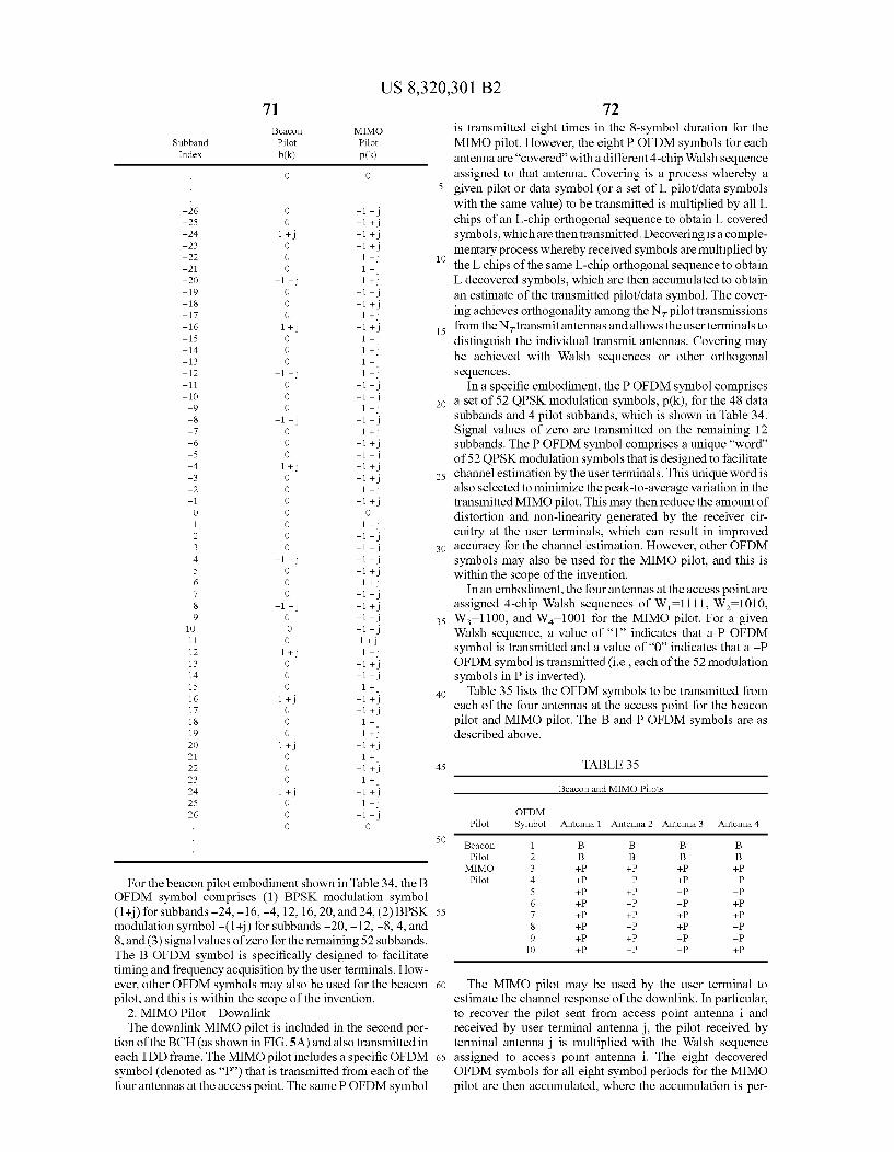
US 8,320,301 B2 71 Beacon MIMO
Subband Pilot Pilot Index b(k) p(k)
O O
-26 O -1 -
-25 O -1 + -24 1 + -1 + -23 O -1 + -22 O - -21 O - -20 -1 - + -19 O -1 -
-18 O -1 + -17 O + -16 + i -1 + -15 O - -14 O + -13 O - -12 - -11 O -1 - -10 O -1 - -9 O - -8 -1 -
-7 O + -6 O -1 + -5 O -1 -
-4 + i -1 + -3 O -1 + -2 O - -1 O -1 + O O O 1 O - 2 O -1 - 3 O -1 -
4 -1 - -1 - 5 O -1 + 6 O + 7 O -1 -
8 -1 - -1 + 9 O -1 -
10 O -1 -
11 O 1 + 12 1 + - 13 O -1 + 14 O -1 -
15 O + 16 1 + -1 + 17 O -1 + 18 O - 19 O + 2O 1 + -1 + 21 O + 22 O -1 + 23 O + 24 1 + -1 + 25 O - 26 O -1 -
O O
For the beacon pilot embodiment shown in Table 34, the B OFDM symbol comprises (1) BPSK modulation symbol (1+) for subbands -24, -16, -4, 12, 16, 20, and 24, (2) BPSK modulation symbol -(1+) for Subbands -20, -12, -8, 4, and 8, and (3) signal values of Zero for the remaining 52 subbands. The B OFDM symbol is specifically designed to facilitate timing and frequency acquisition by the user terminals. How ever, other OFDM symbols may also be used for the beacon pilot, and this is within the scope of the invention.
2. MIMO Pilot Downlink The downlink MIMO pilot is included in the second por
tion of the BCH (as shown in FIG.5A) and also transmitted in each TDD frame. The MIMO pilot includes a specific OFDM symbol (denoted as “P”) that is transmitted from each of the four antennas at the access point. The same POFDM symbol
10
15
25
30
35
40
45
50
55
60
65
72 is transmitted eight times in the 8-symbol duration for the MIMO pilot. However, the eight P OFDM symbols for each antenna are “covered with a different 4-chip Walsh sequence assigned to that antenna. Covering is a process whereby a given pilot or data symbol (or a set of L. pilot/data symbols with the same value) to be transmitted is multiplied by all L chips of an L-chip orthogonal sequence to obtain L covered symbols, which are then transmitted. Decovering is a comple mentary process whereby received symbols are multiplied by the L chips of the same L-chip orthogonal sequence to obtain L decovered symbols, which are then accumulated to obtain an estimate of the transmitted pilot/data symbol. The cover ing achieves orthogonality among the N pilot transmissions from the Nitransmit antennas and allows the user terminals to distinguish the individual transmit antennas. Covering may be achieved with Walsh sequences or other orthogonal Sequences.
In a specific embodiment, the POFDM symbol comprises a set of 52 QPSK modulation symbols, p(k), for the 48 data subbands and 4 pilot subbands, which is shown in Table 34. Signal values of Zero are transmitted on the remaining 12 subbands. The POFDM symbol comprises a unique “word of 52 QPSK modulation symbols that is designed to facilitate channel estimation by the user terminals. This unique word is also selected to minimize the peak-to-average variation in the transmitted MIMO pilot. This may then reduce the amount of distortion and non-linearity generated by the receiver cir cuitry at the user terminals, which can result in improved accuracy for the channel estimation. However, other OFDM symbols may also be used for the MIMO pilot, and this is within the scope of the invention.
In an embodiment, the four antennas at the access point are assigned 4-chip Walsh sequences of W=1111, W=1010, W=1100, and W-1001 for the MIMO pilot. For a given Walsh sequence, a value of “1” indicates that a P OFDM symbol is transmitted and a value of “0” indicates that a -P OFDM symbol is transmitted (i.e., each of the 52 modulation symbols in P is inverted).
Table 35 lists the OFDM symbols to be transmitted from each of the four antennas at the access point for the beacon pilot and MIMO pilot. The B and P OFDM symbols are as described above.
TABLE 35
Beacon and MIMO Pilots
OFDM Pilot Symbol Antenna 1 Antenna 2 Antenna 3 Antenna 4
Beacon 1 B B B B Pilot 2 B B B B MIMO 3 --P --P --P --P Pilot 4 --P -P --P -P
5 --P --P -P -P 6 --P -P -P --P 7 --P --P --P --P 8 --P -P --P -P 9 --P --P -P -P 10 --P -P -P --P
The MIMO pilot may be used by the user terminal to estimate the channel response of the downlink. In particular, to recover the pilot sent from access point antenna i and received by user terminal antenna j, the pilot received by terminal antenna j is multiplied with the Walsh sequence assigned to access point antenna i. The eight decovered OFDM symbols for all eight symbol periods for the MIMO pilot are then accumulated, where the accumulation is per
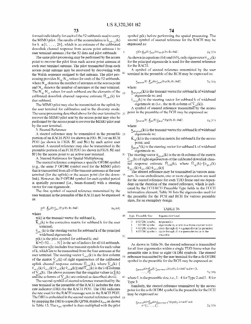
US 8,320,301 B2 73
formed individually for each of the 52 subbands used to carry the MIMO pilot. The results of the accumulation is ha, , (k) for k=t{1,..., 26}, which is an estimate of the calibrated downlink channel response from access point antenna i to user terminal antennaj for the 52 data and pilot subbands.
The same pilot processing may be performed by the access point to recover the pilot from each access point antenna at each user terminal antenna. The pilot transmitted from each access point antenna may be recovered by decovering with the Walsh sequence assigned to that antenna. The pilot pro cessing provides N.N., values for each of the 52 subbands, where N denotes the number of antennas at the access point and N denotes the number of antennas at the user terminal. The N.N., values for each subband are the elements of the calibrated downlink channel response estimate H(k) for that Subband.
The MIMO pilot may also be transmitted on the uplink by the user terminal for calibration and in the diversity mode. The same processing described above for the user terminal to recover the MIMO pilot sent by the access point may also be performed by the access point to recover the MIMO pilot sent by the user terminal.
3. Steered Reference A steered reference may be transmitted in the preamble
portion of an RACH PDU (as shown in FIG.5C) or an RCH PDU (as shown in FIGS. 5E and 5G) by each active user terminal. A steered reference may also be transmitted in the preamble portion of an FCH PDU (as shown in FIGS.5E and 5F) by the access point to an active user terminal.
A. Steered Reference for Spatial Multiplexing The steered reference comprises a specific OFDM symbol
(e.g., the same POFDM symbol used for the MIMO pilot) that is transmitted from all of the transmit antennas at the user terminal (for the uplink) or the access point (for the down link). However, the POFDM symbol for each symbol period is spatially processed (i.e., beam-formed) with a steering vector for one eigenmode. The first symbol of steered reference transmitted by the
user terminal in the preamble of the RACH may be expressed aS
x(k)-K (k), (k)p(k), for ke K, Eq. (64) where
X(k) is the transmit vector for subband k: K(k) is the correction matrix for subband k for the user
terminal; v, (k) is the steering vector for Subband k of the principal
wideband eigenmode: p(k) is the pilot symbol for subband k; and K={-32,..., 31} is the set of indices for all 64 Subbands.
The vector X(k) includes four transmit symbols for each value ofk, which are to be transmitted from the four antennas at the user terminal. The steering vector v, (k) is the first column of the matrix V(k) of right eigenvectors of the calibrated uplink channel response estimate He (k), where V(k)- v, (k) V,2(k) V, s(k) Via(k) and V(k) is the i-th column of V(k). The above assumes that the singular values in S(k) and the columns of V(k) are ordered as described above. The second symbol of steered reference transmitted by the
user terminal in the preamble of the RACH includes the data rate indicator (DRI) for the RACH PDU. The DRI indicates the rate used for the RACH message sent in the RACH PDU. The DRI is embedded in the second steered reference symbol by mapping the DRI to a specific QPSK symbols, as shown in Table 15. The s symbol is then multiplied with the pilot
10
15
25
30
35
40
45
50
55
60
65
74 symbol p(k) before performing the spatial processing. The second symbol of steered reference for the RACH may be expressed as:
x(k)-K (k), (k) saip(k), for keK'. Eq.(65) As shown inequations (64) and (65), only eigenvectorv, (k) for the principal eigenmode is used for the steered reference for the RACH. A symbol of steered reference transmitted by the user
terminal in the preamble of the RCH may be expressed as:
(k)=K, (R)'s up.srin (k)p(k), for ke K, Eq.(66) where
x(k) is the transmit vector for Subband k of wideband Teigenmode m; and v(k) is the steering vector for Subband k of wideband
eigenmode m (i.e., the m-th column of V(k)). A symbol of steered reference transmitted by the access
point in the preamble of the FCH may be expressed as:
(k)-K (k) a afra *(k)p(k), for ke K, Eq. (67)
where
X(k) is the transmit vector for Subband k of wideband eigenmode m;
K(k) is the correction matrix for subband kfor the access point; and
(*(k) is the steering vector for Subband k of wideband eigenmodem.
The steering vector f(k) is the m-th column of the matrix U.(k) of right eigenvectors of the calibrated downlink chan nel response estimate H(k), where U(k)-(i.e.,(k) tle2(k) us(k) tea(k)). The steered reference may be transmitted in various man
ners. In one embodiment, one or more eigenvectors are used for the steered reference for each TDD frame and are depen dent on the duration of the steered reference, which is indi cated by the FCH/RCH Preamble Type fields in the FCCH information element. Table 36 lists the eigenmodes used for the preamble for the FCH and RCH for various preamble sizes, for an exemplary design.
ap.ni
TABLE 36
Type Preamble Size Eigenmodes Used
O O OFDM symbol 1 OFDM symbol 4 OFDM symbols 8 OFDM symbols
no preamble eigenmodem, where m = frame counter mod 4 cycle through all 4 eigenmodes in the preamble cycle through all 4 eigenmodes twice in the preamble
s As shown in Table 36, the steered reference is transmitted
for all four eigenmodes within a single TDD frame when the preamble size is four or eight OFDM symbols. The steered reference transmitted by the user terminal for the n-th OFDM symbol in the preamble for the RCH may be expressed as:
yer,(k)-K (k), a 4(k)p(k), for keK and n={1, . . . , L3,
where L is the preamble size, i.e., L-4 for Type 2 and L=8 for Type 3.
Similarly, the steered reference transmitted by the access point for the n-th OFDM symbol in the preamble for the FCH may be expressed as:
Eq.(68)
xas,(k)-K (k)a, a *(k)p(k), for keK and
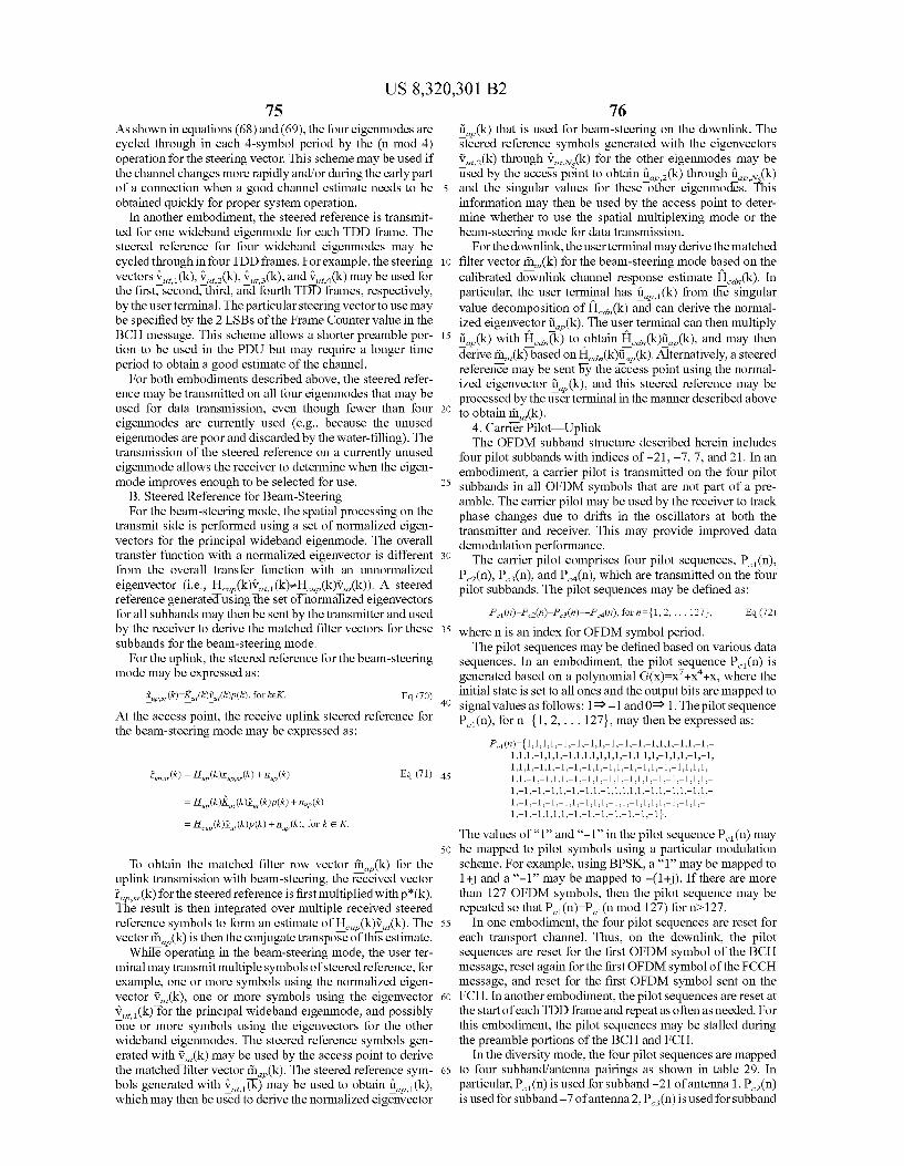
US 8,320,301 B2 75
As shown in equations (68) and (69), the four eigenmodes are cycled through in each 4-symbol period by the (n mod 4) operation for the steering vector. This scheme may be used if the channel changes more rapidly and/or during the early part of a connection when a good channel estimate needs to be obtained quickly for proper system operation.
In another embodiment, the steered reference is transmit ted for one wideband eigenmode for each TDD frame. The steered reference for four wideband eigenmodes may be cycled through in four TDD frames. For example, the steering vectors v, (k), v.2(k), V,is (k), and V, (k) may be used for the first, second, third, and fourth TDD frames, respectively, by the user terminal. The particular steering vector to use may be specified by the 2 LSBs of the Frame Counter value in the BCH message. This scheme allows a shorter preamble por tion to be used in the PDU but may require a longer time period to obtain a good estimate of the channel.
For both embodiments described above, the steered refer ence may be transmitted on all four eigenmodes that may be used for data transmission, even though fewer than four eigenmodes are currently used (e.g., because the unused eigenmodes are poor and discarded by the water-filling). The transmission of the steered reference on a currently unused eigenmode allows the receiver to determine when the eigen mode improves enough to be selected for use.
B. Steered Reference for Beam-Steering For the beam-steering mode, the spatial processing on the
transmit side is performed using a set of normalized eigen vectors for the principal wideband eigenmode. The overall transfer function with a normalized eigenvector is different from the overall transfer function with an unnormalized
eigenvector (i.e., H(k)V(k)zH(k)V(k)). A steered reference generated using the set of normalized eigenvectors for all subbands may then be sent by the transmitter and used by the receiver to derive the matched filter vectors for these Subbands for the beam-steering mode.
For the uplink, the steered reference for the beam-steering mode may be expressed as:
i.e.(k)-K (k),(k)p(k), for keK. Eq. (70)
At the access point, the receive uplink steered reference for the beam-steering mode may be expressed as:
(k) + n (k) -up Eq. (71)
= H(k), (k)p(k) + n (k), for ke K.
To obtain the matched filter row vector ?in(k) for the uplink transmission with beam-steering, the received vector f(k) for the steered reference is first multiplied with p*(k). The result is then integrated over multiple received steered reference symbols to form an estimate of H(k)V(k). The vector ?in(k) is then the conjugate transpose of this estimate.
While operating in the beam-steering mode, the user ter minal may transmit multiple symbols of steered reference, for example, one or more symbols using the normalized eigen vector V(k), one or more symbols using the eigenvector v, (k) for the principal wideband eigenmode, and possibly one or more symbols using the eigenvectors for the other wideband eigenmodes. The steered reference symbols gen erated with V(k) may be used by the access point to derive the matched filter vector ?in(k). The steered reference sym bols generated with v(k) may be used to obtain a (k), which may then be used to derive the normalized eigenvector
5
10
15
25
30
35
40
45
50
55
60
65
76 ü(k) that is used for beam-steering on the downlink. The steered reference symbols generated with the eigenvectors v2(k) through Vx(k) for the other eigenmodes may be used by the access point to obtain (k) through uv.(k) and the singular values for these other eigenmodes. This information may then be used by the access point to deter mine whether to use the spatial multiplexing mode or the beam-steering mode for data transmission.
For the downlink, the user terminal may derive the matched filter vector ?in(k) for the beam-steering mode based on the calibrated downlink channel response estimate H.,(k). In particular, the user terminal has ill (k) from the singular value decomposition of H.,(k) and can derive the normal ized eigenvector f(k). The user terminal can then multiply ti,(k) with H.(k) to obtain H...(k)ü(k), and may then derive ii, (k) based on H.a,(k)f (k). Alternatively, a steered reference may be sent by the access point using the normal ized eigenvector f(k), and this steered reference may be processed by the user terminal in the manner described above to obtain rin(k).
4. Carrier Pilot Uplink The OFDM subband structure described herein includes
four pilot subbands with indices of -21, -7, 7, and 21. In an embodiment, a carrier pilot is transmitted on the four pilot subbands in all OFDM symbols that are not part of a pre amble. The carrier pilot may be used by the receiver to track phase changes due to drifts in the oscillators at both the transmitter and receiver. This may provide improved data demodulation performance. The carrier pilot comprises four pilot sequences, P. (n),
P(n), P(n), and P(n), which are transmitted on the four pilot Subbands. The pilot sequences may be defined as:
P (n)=P(n)=P(n)=-P(n), for n = {1, 2, ... 127, Eq. (72)
where n is an index for OFDM symbol period. The pilot sequences may be defined based on various data
sequences. In an embodiment, the pilot sequence P(n) is generated based on a polynomial G(x)=x'+x+x, where the initial state is set to all ones and the output bits are mapped to signal values as follows: 1-1 and 0 1. The pilot sequence P (n), for n={1, 2, ... 127, may then be expressed as:
P (n)={1,1,1,1-1.-1.-1.1.-1.-1.-1.-1,1,1,–1,1-1- 1,1,1-1,1,1,–1,1,1,1,1,1,1-1,11,1-1,1,1-1-1, 1,1,1-1,1-1-1-1,1-1,1-1-1,1-1-1,1,1,1, 1,1-1-1,1,1-1-1,1-1,1,–1,1,1-1.-1.-1,1,1,– 1.-1.-1.-1,1-1-1,1-1,1,1,1,1-1,1,–1,1-1,1,– 1.-1.-1.-1.-1,1-1,1,1-1,1-1,1,1,1-1-1,1,– 1.-1.-1,1,1,1-1.-1.-1.-1.-1.-1.-1. 3 ks
The values of “1” and “-1 in the pilot sequence P. (n) may be mapped to pilot symbols using a particular modulation scheme. For example, using BPSK, a “1” may be mapped to 1+ and a “-1” may be mapped to -(1+). If there are more than 127 OFDM symbols, then the pilot sequence may be repeated so that P(n)=P(n mod 127) for n>127.
In one embodiment, the four pilot sequences are reset for each transport channel. Thus, on the downlink, the pilot sequences are reset for the first OFDM symbol of the BCH message, reset again for the first OFDM symbol of the FCCH message, and reset for the first OFDM symbol sent on the FCH. In another embodiment, the pilot sequences are reset at the start of each TDD frame and repeat as often as needed. For this embodiment, the pilot sequences may be stalled during the preamble portions of the BCH and FCH.
In the diversity mode, the four pilot sequences are mapped to four Subband/antenna pairings as shown in table 29. In particular, P. (n) is used for Subband -21 of antenna 1, P(n) is used for subband-7 of antenna 2, P(n) is used for subband
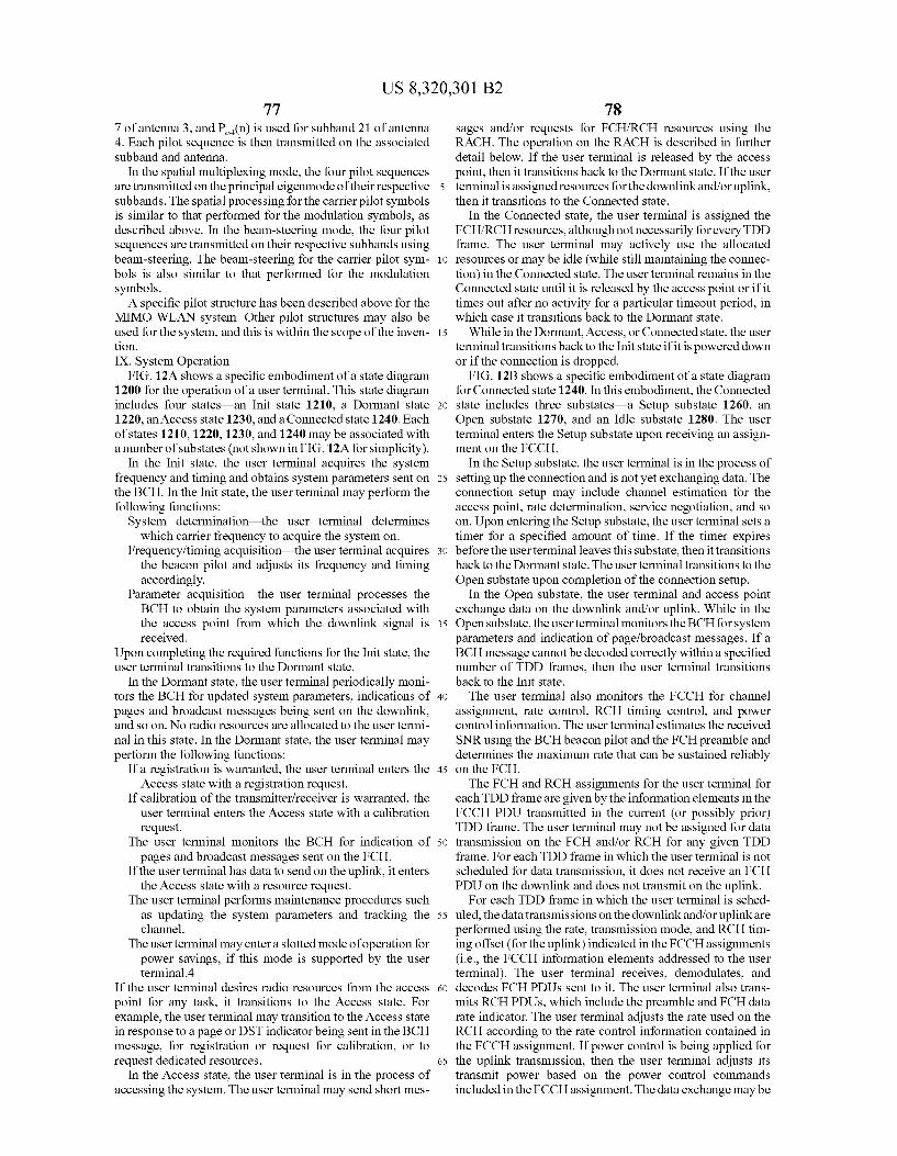
US 8,320,301 B2 77
7 of antenna 3, and P(n) is used for Subband 21 of antenna 4. Each pilot sequence is then transmitted on the associated Subband and antenna.
In the spatial multiplexing mode, the four pilot sequences are transmitted on the principal eigenmode of their respective Subbands. The spatial processing for the carrier pilot symbols is similar to that performed for the modulation symbols, as described above. In the beam-steering mode, the four pilot sequences are transmitted on their respective Subbands using beam-steering. The beam-steering for the carrier pilot sym bols is also similar to that performed for the modulation symbols. A specific pilot structure has been described above for the
MIMO WLAN system. Other pilot structures may also be used for the system, and this is within the scope of the inven tion. IX. System Operation
FIG. 12A shows a specific embodiment of a state diagram 1200 for the operation of a user terminal. This state diagram includes four states—an Init state 1210, a Dormant state 1220, an Access state 1230, and a Connected state 1240. Each of states 1210, 1220, 1230, and 1240 may be associated with a number of substates (not shown in FIG. 12A for simplicity).
In the Init state, the user terminal acquires the system frequency and timing and obtains system parameters sent on the BCH. In the Init state, the user terminal may perform the following functions:
System determination—the user terminal determines which carrier frequency to acquire the system on.
Frequency/timing acquisition—the user terminal acquires the beacon pilot and adjusts its frequency and timing accordingly.
Parameter acquisition—the user terminal processes the BCH to obtain the system parameters associated with the access point from which the downlink signal is received.
Upon completing the required functions for the Init state, the user terminal transitions to the Dormant state.
In the Dormant state, the user terminal periodically moni tors the BCH for updated system parameters, indications of pages and broadcast messages being sent on the downlink, and so on. No radio resources are allocated to the user termi nal in this state. In the Dormant state, the user terminal may perform the following functions:
If a registration is warranted, the user terminal enters the Access state with a registration request.
If calibration of the transmitter/receiver is warranted, the user terminal enters the Access State with a calibration request.
The user terminal monitors the BCH for indication of pages and broadcast messages sent on the FCH.
If the user terminal has data to send on the uplink, it enters the Access State with a resource request.
The user terminal performs maintenance procedures such as updating the system parameters and tracking the channel.
The user terminal may entera slotted mode of operation for power savings, if this mode is Supported by the user terminal.4
If the user terminal desires radio resources from the access point for any task, it transitions to the Access state. For example, the user terminal may transition to the Access state in response to a page or DST indicator being sent in the BCH message, for registration or request for calibration, or to request dedicated resources.
In the Access state, the user terminal is in the process of accessing the system. The user terminal may send short mes
10
15
25
30
35
40
45
50
55
60
65
78 sages and/or requests for FCH/RCH resources using the RACH. The operation on the RACH is described in further detail below. If the user terminal is released by the access point, then it transitions back to the Dormant state. If the user terminal is assigned resources for the downlink and/or uplink, then it transitions to the Connected state.
In the Connected State, the user terminal is assigned the FCH/RCH resources, although not necessarily for every TDD frame. The user terminal may actively use the allocated resources or may be idle (while still maintaining the connec tion) in the Connected state. The user terminal remains in the Connected state until it is released by the access point or if it times out after no activity for a particular timeout period, in which case it transitions back to the Dormant state.
While in the Dormant, Access, or Connected state, the user terminal transitions back to the Init state if it is powered down or if the connection is dropped.
FIG. 12B shows a specific embodiment of a state diagram for Connected state 1240. In this embodiment, the Connected state includes three substates—a Setup substate 1260, an Open substate 1270, and an Idle substate 1280. The user terminal enters the Setup Substate upon receiving an assign ment on the FCCH.
In the Setup substate, the user terminal is in the process of setting up the connection and is not yet exchanging data. The connection setup may include channel estimation for the access point, rate determination, service negotiation, and so on. Upon entering the Setup Substate, the user terminal sets a timer for a specified amount of time. If the timer expires before the user terminal leaves this substate, then it transitions back to the Dormant state. The user terminal transitions to the Open substate upon completion of the connection setup.
In the Open Substate, the user terminal and access point exchange data on the downlink and/or uplink. While in the Open substate, the user terminal monitors the BCH for system parameters and indication of page/broadcast messages. If a BCH message cannot be decoded correctly within a specified number of TDD frames, then the user terminal transitions back to the Init state. The user terminal also monitors the FCCH for channel
assignment, rate control, RCH timing control, and power control information. The user terminal estimates the received SNR using the BCH beacon pilot and the FCH preamble and determines the maximum rate that can be sustained reliably on the FCH. The FCH and RCH assignments for the user terminal for
each TDD frame are given by the information elements in the FCCH PDU transmitted in the current (or possibly prior) TDD frame. The user terminal may not be assigned for data transmission on the FCH and/or RCH for any given TDD frame. For each TDD frame in which the user terminal is not scheduled for data transmission, it does not receive an FCH PDU on the downlink and does not transmit on the uplink.
For each TDD frame in which the user terminal is sched uled, the data transmissions on the downlink and/or uplinkare performed using the rate, transmission mode, and RCH tim ing offset (for the uplink) indicated in the FCCH assignments (i.e., the FCCH information elements addressed to the user terminal). The user terminal receives, demodulates, and decodes FCH PDUs sent to it. The user terminal also trans mits RCH PDUs, which include the preamble and FCH data rate indicator. The user terminal adjusts the rate used on the RCH according to the rate control information contained in the FCCH assignment. If power control is being applied for the uplink transmission, then the user terminal adjusts its transmit power based on the power control commands included in the FCCH assignment. The data exchange may be
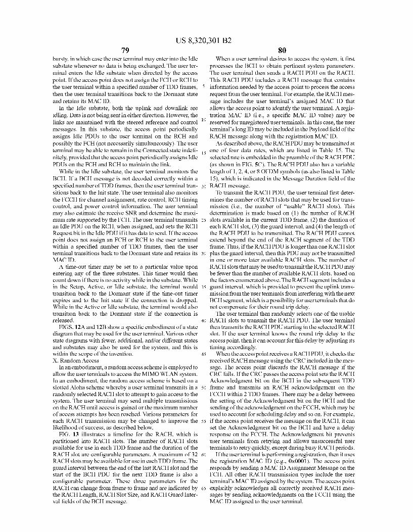
US 8,320,301 B2 79
bursty, in which case the user terminal may enter into the Idle Substate whenever no data is being exchanged. The user ter minal enters the Idle substate when directed by the access point. If the access point does not assign the FCH or RCH to the user terminal within a specified number of TDD frames, then the user terminal transitions back to the Dormant state and retains its MAC ID.
In the Idle substate, both the uplink and downlink are idling. Data is not being sent in either direction. However, the links are maintained with the steered reference and control messages. In this substate, the access point periodically assigns Idle PDUs to the user terminal on the RCH and possibly the FCH (not necessarily simultaneously). The user terminal may be able to remain in the Connected state indefi nitely, provided that the access point periodically assigns Idle PDUs on the FCH and RCH to maintain the link.
While in the Idle substate, the user terminal monitors the BCH. If a BCH message is not decoded correctly within a specified number of TDD frames, then the user terminal tran sitions back to the Init state. The user terminal also monitors the FCCH for channel assignment, rate control, RCH timing control, and power control information. The user terminal may also estimate the receive SNR and determine the maxi mum rate supported by the FCH. The user terminal transmits an Idle PDU on the RCH, when assigned, and sets the RCH Request bit in the Idle PDU if it has data to send. If the access point does not assign an FCH or RCH to the user terminal within a specified number of TDD frames, then the user terminal transitions back to the Dormant state and retains its MAC ID. A time-out timer may be set to a particular value upon
entering any of the three substates. This timer would then count down if there is no activity while in the substate. While in the Setup, Active, or Idle substate, the terminal would transition back to the Dormant state if the time-out timer expires and to the Init state if the connection is dropped. While in the Active or Idle substate, the terminal would also transition back to the Dormant state if the connection is released.
FIGS. 12A and 12B show a specific embodiment of a state diagram that may be used for the user terminal. Various other state diagrams with fewer, additional, and/or different states and Substates may also be used for the system, and this is within the scope of the invention. X. Random Access
In an embodiment, a random access scheme is employed to allow the user terminals to access the MIMO WLAN system. In an embodiment, the random access Scheme is based on a slotted Aloha Scheme whereby a user terminal transmits in a randomly selected RACH slot to attempt to gain access to the system. The user terminal may send multiple transmissions on the RACH until access is gained or the maximum number of access attempts has been reached. Various parameters for each RACH transmission may be changed to improve the likelihood of success, as described below.
FIG. 13 illustrates a timeline for the RACH, which is partitioned into RACH slots. The number of RACH slots available for use in each TDD frame and the duration of the RACH slot are configurable parameters. A maximum of 32 RACH slots may be available for use in each TDD frame. The guard interval between the end of the last RACH slot and the Start of the BCH PDU for the next TDD frame is also a configurable parameter. These three parameters for the RACH can change from frame to frame and are indicated by the RACH Length, RACHSlot Size, and RACH Guard Inter val fields of the BCH message.
10
15
25
30
35
40
45
50
55
60
65
80 When a user terminal desires to access the system, it first
processes the BCH to obtain pertinent system parameters. The user terminal then sends a RACH PDU on the RACH. This RACH PDU includes a RACH message that contains information needed by the access point to process the access request from the user terminal. For example, the RACH mes sage includes the user terminals assigned MAC ID that allows the access point to identify the user terminal. A regis tration MAC ID (i.e., a specific MAC ID value) may be reserved for unregistered user terminals. In this case, the user terminal's long ID may be included in the Payload field of the RACH message along with the registration MAC ID. As described above, the RACHPDU may be transmitted at
one of four data rates, which are listed in Table 15. The selected rate is embedded in the preamble of the RACHPDU (as shown in FIG.5C). The RACH PDU also has a variable length of 1, 2, 4, or 8 OFDM symbols (as also listed in Table 15), which is indicated in the Message Duration field of the RACH message. To transmit the RACH PDU, the user terminal first deter
mines the number of RACH slots that may be used for trans mission (i.e., the number of “usable RACH slots). This determination is made based on (1) the number of RACH slots available in the current TDD frame, (2) the duration of each RACH slot, (3) the guard interval, and (4) the length of the RACH PDU to be transmitted. The RACH PDU cannot extend beyond the end of the RACH segment of the TDD frame. Thus, if the RACHPDU is longer than one RACH slot plus the guard interval, then this PDU may not be transmitted in one or more later available RACH slots. The number of RACH slots that may be used to transmit the RACHPDU may be fewer than the number of available RACH slots, based on the factors enumerated above. The RACH segment includes a guard interval, which is provided to prevent the uplink trans mission from the user terminals from interfering with the next BCH segment, which is a possibility for user terminals that do not compensate for their round trip delay. The user terminal then randomly selects one of the usable
RACH slots to transmit the RACH PDU. The user terminal then transmits the RACHPDU starting in the selected RACH slot. If the user terminal knows the round trip delay to the access point, then it can account for this delay by adjusting its timing accordingly. When the access point receives a RACHPDU, it checks the
received RACH message using the CRC included in the mes sage. The access point discards the RACH message if the CRC fails. If the CRC passes the access point sets the RACH Acknowledgment bit on the BCH in the subsequent TDD frame and transmits an RACH acknowledgement on the FCCH within 2 TDD frames. There may be a delay between the setting of the Acknowledgment bit on the BCH and the sending of the acknowledgment on the FCCH, which may be used to account for scheduling delay and so on. For example, if the access point receives the message on the RACH, it can set the Acknowledgment bit on the BCH and have a delay response on the FCCH. The Acknowledgment bit prevents user terminals from retrying and allows unsuccessful user terminals to retry quickly, except during busy RACH periods.
If the user terminal is performing a registration, then it uses the registration MAC ID (e.g. 0x0001). The access point responds by sending a MAC ID Assignment Message on the FCH. All other RACH transmission types include the user terminal's MAC ID assigned by the system. The access point explicitly acknowledges all correctly received RACH mes sages by sending acknowledgments on the FCCH using the MAC ID assigned to the user terminal.
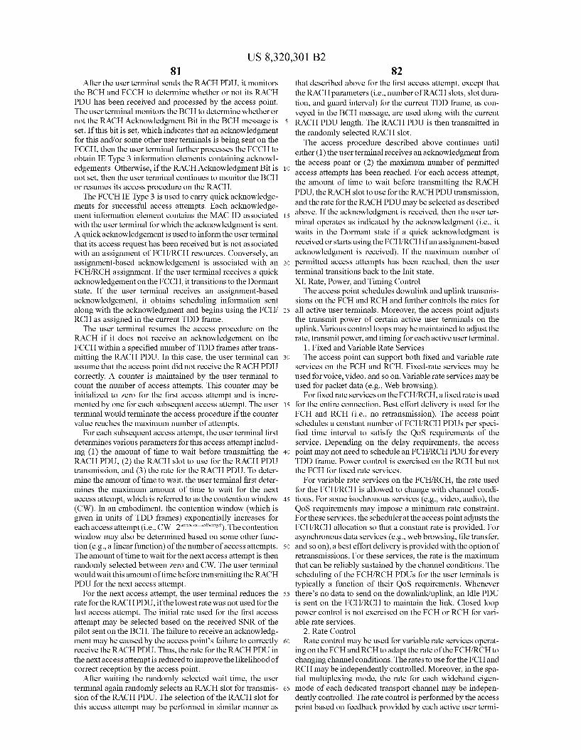
US 8,320,301 B2 81
After the user terminal sends the RACH PDU, it monitors the BCH and FCCH to determine whether or not its RACH PDU has been received and processed by the access point. The user terminal monitors the BCH to determine whether or not the RACH Acknowledgment Bit in the BCH message is set. If this bit is set, which indicates that an acknowledgment for this and/or some other user terminals is being sent on the FCCH, then the user terminal further processes the FCCH to obtain IEType 3 information elements containing acknowl edgements. Otherwise, if the RACH Acknowledgment Bit is not set, then the user terminal continues to monitor the BCH or resumes its access procedure on the RACH. The FCCHIEType 3 is used to carry quick acknowledge
ments for Successful access attempts. Each acknowledge ment information element contains the MAC ID associated with the user terminal for which the acknowledgment is sent. A quick acknowledgement is used to inform the user terminal that its access request has been received but is not associated with an assignment of FCH/RCH resources. Conversely, an assignment-based acknowledgement is associated with an FCH/RCH assignment. If the user terminal receives a quick acknowledgement on the FCCH, it transitions to the Dormant state. If the user terminal receives an assignment-based acknowledgement, it obtains scheduling information sent along with the acknowledgment and begins using the FCH/ RCH as assigned in the current TDD frame. The user terminal resumes the access procedure on the
RACH if it does not receive an acknowledgement on the FCCH within a specified number of TDD frames after trans mitting the RACH PDU. In this case, the user terminal can assume that the access point did not receive the RACH PDU correctly. A counter is maintained by the user terminal to count the number of access attempts. This counter may be initialized to Zero for the first access attempt and is incre mented by one for each Subsequent access attempt. The user terminal would terminate the access procedure if the counter value reaches the maximum number of attempts.
For each Subsequent access attempt, the user terminal first determines various parameters for this access attempt includ ing (1) the amount of time to wait before transmitting the RACH PDU, (2) the RACH slot to use for the RACH PDU transmission, and (3) the rate for the RACH PDU. To deter mine the amount of time to wait, the user terminal first deter mines the maximum amount of time to wait for the next access attempt, which is referred to as the contention window (CW). In an embodiment, the contention window (which is given in units of TDD frames) exponentially increases for each access attempt (i.e., CW-2* “"). The contention window may also be determined based on some other func tion (e.g., a linear function) of the number of access attempts. The amount of time to wait for the next access attempt is then randomly selected between Zero and CW. The user terminal would wait this amount of time before transmitting the RACH PDU for the next access attempt.
For the next access attempt, the user terminal reduces the rate for the RACHPDU, if the lowest rate was not used for the last access attempt. The initial rate used for the first access attempt may be selected based on the received SNR of the pilot sent on the BCH. The failure to receive an acknowledg ment may be caused by the access points failure to correctly receive the RACHPDU. Thus, the rate for the RACHPDU in the next access attempt is reduced to improve the likelihood of correct reception by the access point.
After waiting the randomly selected wait time, the user terminal again randomly selects an RACH slot for transmis Sion of the RACH PDU. The Selection of the RACH slot for this access attempt may be performed in similar manner as
10
15
25
30
35
40
45
50
55
60
65
82 that described above for the first access attempt, except that the RACH parameters (i.e., number of RACH slots, slot dura tion, and guard interval) for the current TDD frame, as con veyed in the BCH message, are used along with the current RACH PDU length. The RACH PDU is then transmitted in the randomly selected RACH slot. The access procedure described above continues until
either (1) the user terminal receives an acknowledgment from the access point or (2) the maximum number of permitted access attempts has been reached. For each access attempt, the amount of time to wait before transmitting the RACH PDU, the RACH slot to use for the RACHPDU transmission, and the rate for the RACH PDU may be selected as described above. If the acknowledgment is received, then the user ter minal operates as indicated by the acknowledgment (i.e., it waits in the Dormant state if a quick acknowledgment is received or starts using the FCH/RCH if an assignment-based acknowledgment is received). If the maximum number of permitted access attempts has been reached, then the user terminal transitions back to the Init state. XI. Rate, Power, and Timing Control The access point Schedules downlink and uplink transmis
sions on the FCH and RCH and further controls the rates for all active user terminals. Moreover, the access point adjusts the transmit power of certain active user terminals on the uplink. Various control loops may be maintained to adjust the rate, transmit power, and timing for each active user terminal.
1. Fixed and Variable Rate Services The access point can Support both fixed and variable rate
services on the FCH and RCH. Fixed-rate services may be used for voice, video, and so on. Variable rate services may be used for packet data (e.g., Web browsing).
For fixed rate services on the FCH/RCH, a fixed rate is used for the entire connection. Best effort delivery is used for the FCH and RCH (i.e., no retransmission). The access point schedules a constant number of FCH/RCH PDUs per speci fied time interval to satisfy the QoS requirements of the service. Depending on the delay requirements, the access point may not need to schedule an FCH/RCH PDU for every TDD frame. Power control is exercised on the RCH but not the FCH for fixed rate Services.
For variable rate services on the FCH/RCH, the rate used for the FCH/RCH is allowed to change with channel condi tions. For Some isochronous services (e.g., video, audio), the QoS requirements may impose a minimum rate constraint. For these services, the scheduler at the access point adjusts the FCH/RCH allocation so that a constant rate is provided. For asynchronous data services (e.g., web browsing, file transfer, and so on), a best effort delivery is provided with the option of retransmissions. For these services, the rate is the maximum that can be reliably sustained by the channel conditions. The scheduling of the FCH/RCH PDUs for the user terminals is typically a function of their QoS requirements. Whenever there's no data to send on the downlink/uplink, an Idle PDU is sent on the FCH/RCH to maintain the link. Closed loop power control is not exercised on the FCH or RCH for vari able rate services.
2. Rate Control Rate control may be used for variable rate services operat
ing on the FCH and RCH to adapt the rate of the FCH/RCH to changing channel conditions. The rates to use for the FCH and RCH may be independently controlled. Moreover, in the spa tial multiplexing mode, the rate for each wideband eigen mode of each dedicated transport channel may be indepen dently controlled. The rate control is performed by the access point based on feedback provided by each active user termi
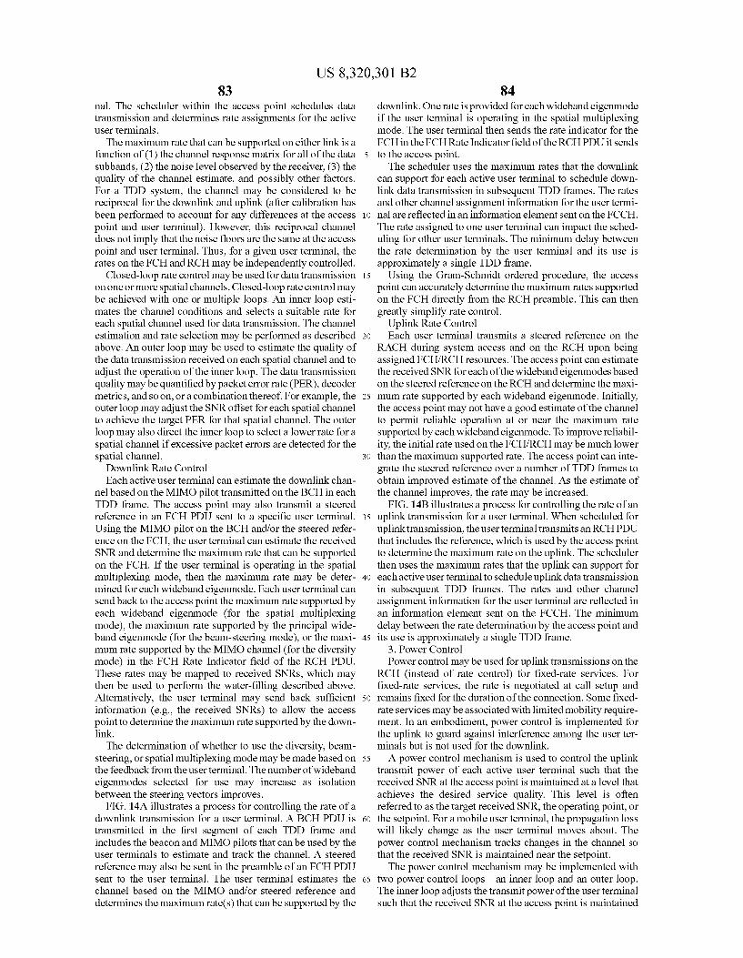
US 8,320,301 B2 83
nal. The scheduler within the access point schedules data transmission and determines rate assignments for the active user terminals.
The maximum rate that can be supported on either link is a function of (1) the channel response matrix for all of the data subbands, (2) the noise level observed by the receiver, (3) the quality of the channel estimate, and possibly other factors. For a TDD system, the channel may be considered to be reciprocal for the downlink and uplink (after calibration has been performed to account for any differences at the access point and user terminal). However, this reciprocal channel does not imply that the noise floors are the same at the access point and user terminal. Thus, for a given user terminal, the rates on the FCH and RCH may be independently controlled.
Closed-loop rate control may be used for data transmission on one or more spatial channels. Closed-loop rate control may be achieved with one or multiple loops. An inner loop esti mates the channel conditions and selects a Suitable rate for each spatial channel used for data transmission. The channel estimation and rate selection may be performed as described above. An outer loop may be used to estimate the quality of the data transmission received on each spatial channel and to adjust the operation of the inner loop. The data transmission quality may be quantified by packet error rate (PER), decoder metrics, and so on, or a combination thereof. For example, the outer loop may adjust the SNR offset for each spatial channel to achieve the target PER for that spatial channel. The outer loop may also direct the inner loop to select a lower rate for a spatial channel if excessive packet errors are detected for the spatial channel.
Downlink Rate Control Each active user terminal can estimate the downlink chan
nel based on the MIMO pilot transmitted on the BCH in each TDD frame. The access point may also transmit a steered reference in an FCH PDU sent to a specific user terminal. Using the MIMO pilot on the BCH and/or the steered refer ence on the FCH, the user terminal can estimate the received SNR and determine the maximum rate that can be supported on the FCH. If the user terminal is operating in the spatial multiplexing mode, then the maximum rate may be deter mined for each wideband eigenmode. Each user terminal can send back to the access point the maximum rate Supported by each wideband eigenmode (for the spatial multiplexing mode), the maximum rate Supported by the principal wide band eigenmode (for the beam-steering mode), or the maxi mum rate supported by the MIMO channel (for the diversity mode) in the FCH Rate Indicator field of the RCH PDU. These rates may be mapped to received SNRs, which may then be used to perform the water-filling described above. Alternatively, the user terminal may send back sufficient information (e.g., the received SNRs) to allow the access point to determine the maximum rate Supported by the down link. The determination of whether to use the diversity, beam
steering, or spatial multiplexing mode may be made based on the feedback from the user terminal. The number of wideband eigenmodes selected for use may increase as isolation between the steering vectors improves.
FIG. 14A illustrates a process for controlling the rate of a downlink transmission for a user terminal. A BCH PDU is transmitted in the first segment of each TDD frame and includes the beacon and MIMO pilots that can be used by the user terminals to estimate and track the channel. A steered reference may also be sent in the preamble of an FCH PDU sent to the user terminal. The user terminal estimates the channel based on the MIMO and/or steered reference and determines the maximum rate(s) that can be Supported by the
10
15
25
30
35
40
45
50
55
60
65
84 downlink. One rate is provided for each wideband eigenmode if the user terminal is operating in the spatial multiplexing mode. The user terminal then sends the rate indicator for the FCH in the FCHRate Indicator field of the RCHPDU it sends to the access point. The scheduler uses the maximum rates that the downlink
can Support for each active user terminal to schedule down link data transmission in subsequent TDD frames. The rates and other channel assignment information for the user termi nal are reflected in an information element sent on the FCCH. The rate assigned to one user terminal can impact the sched uling for other user terminals. The minimum delay between the rate determination by the user terminal and its use is approximately a single TDD frame.
Using the Gram-Schmidt ordered procedure, the access point can accurately determine the maximum rates Supported on the FCH directly from the RCH preamble. This can then greatly simplify rate control.
Uplink Rate Control Each user terminal transmits a steered reference on the
RACH during system access and on the RCH upon being assigned FCH/RCH resources. The access point can estimate the received SNR for each of the wideband eigenmodes based on the steered reference on the RCH and determine the maxi mum rate Supported by each wideband eigenmode. Initially, the access point may not have a good estimate of the channel to permit reliable operation at or near the maximum rate supported by each wideband eigenmode. To improve reliabil ity, the initial rate used on the FCH/RCH may be much lower than the maximum supported rate. The access point can inte grate the steered reference over a number of TDD frames to obtain improved estimate of the channel. As the estimate of the channel improves, the rate may be increased.
FIG. 14B illustrates a process for controlling the rate of an uplink transmission for a user terminal. When scheduled for uplink transmission, the user terminal transmits an RCHPDU that includes the reference, which is used by the access point to determine the maximum rate on the uplink. The scheduler then uses the maximum rates that the uplink can Support for each active user terminal to schedule uplink data transmission in subsequent TDD frames. The rates and other channel assignment information for the user terminal are reflected in an information element sent on the FCCH. The minimum delay between the rate determination by the access point and its use is approximately a single TDD frame.
3. Power Control Power control may be used for uplink transmissions on the
RCH (instead of rate control) for fixed-rate services. For fixed-rate services, the rate is negotiated at call setup and remains fixed for the duration of the connection. Some fixed rate services may be associated with limited mobility require ment. In an embodiment, power control is implemented for the uplink to guard against interference among the user ter minals but is not used for the downlink. A power control mechanism is used to control the uplink
transmit power of each active user terminal Such that the received SNR at the access point is maintained at a level that achieves the desired service quality. This level is often referred to as the target received SNR, the operating point, or the setpoint. For a mobile user terminal, the propagation loss will likely change as the user terminal moves about. The power control mechanism tracks changes in the channel So that the received SNR is maintained near the setpoint. The power control mechanism may be implemented with
two power control loops—an inner loop and an outer loop. The inner loop adjusts the transmit power of the user terminal such that the received SNR at the access point is maintained
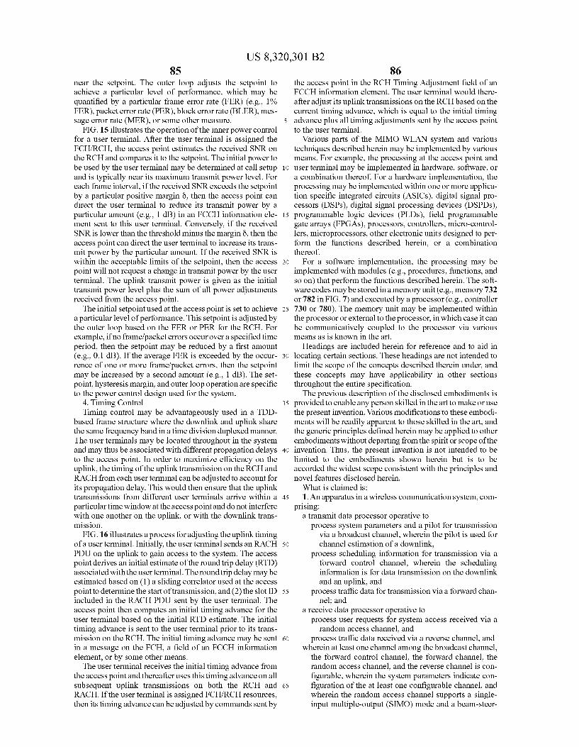
US 8,320,301 B2 85
near the setpoint. The outer loop adjusts the setpoint to achieve a particular level of performance, which may be quantified by a particular frame error rate (FER) (e.g., 1% FER), packet error rate (PER), block error rate (BLER), mes sage error rate (MER), or some other measure.
FIG. 15 illustrates the operation of the inner power control for a user terminal. After the user terminal is assigned the FCH/RCH, the access point estimates the received SNR on the RCH and compares it to the setpoint. The initial power to be used by the user terminal may be determined at call setup and is typically near its maximum transmit power level. For each frame interval, if the received SNR exceeds the setpoint by a particular positive margin Ö, then the access point can direct the user terminal to reduce its transmit power by a particular amount (e.g., 1 dB) in an FCCH information ele ment sent to this user terminal. Conversely, if the received SNR is lower than the threshold minus the margin 8, then the access point can direct the user terminal to increase its trans mit power by the particular amount. If the received SNR is within the acceptable limits of the setpoint, then the access point will not request a change in transmit power by the user terminal. The uplink transmit power is given as the initial transmit power level plus the Sum of all power adjustments received from the access point. The initial setpoint used at the access point is set to achieve
a particular level of performance. This setpoint is adjusted by the outer loop based on the FER or PER for the RCH. For example, if no frame/packet errors occur over a specified time period, then the setpoint may be reduced by a first amount (e.g., 0.1 dB). If the average FER is exceeded by the occur rence of one or more frame/packet errors, then the setpoint may be increased by a second amount (e.g., 1 dB). The set point, hysteresis margin, and outer loop operation are specific to the power control design used for the system.
4. Timing Control Timing control may be advantageously used in a TDD
based frame structure where the downlink and uplink share the same frequency band in a time division duplexed manner. The user terminals may be located throughout in the system and may thus be associated with different propagation delays to the access point. In order to maximize efficiency on the uplink, the timing of the uplink transmission on the RCH and RACH from each user terminal can be adjusted to account for its propagation delay. This would then ensure that the uplink transmissions from different user terminals arrive within a particular time window at the access point and do not interfere with one another on the uplink, or with the downlink trans mission.
FIG.16 illustrates a process for adjusting the uplink timing of a user terminal. Initially, the user terminal sends an RACH PDU on the uplink to gain access to the system. The access point derives an initial estimate of the round trip delay (RTD) associated with the user terminal. The round trip delay may be estimated based on (1) a sliding correlator used at the access point to determine the start of transmission, and (2) the slot ID included in the RACH PDU sent by the user terminal. The access point then computes an initial timing advance for the user terminal based on the initial RTD estimate. The initial timing advance is sent to the user terminal prior to its trans mission on the RCH. The initial timing advance may be sent in a message on the FCH, a field of an FCCH information element, or by Some other means. The user terminal receives the initial timing advance from
the access point and thereafter uses this timing advance on all subsequent uplink transmissions on both the RCH and RACH. If the user terminal is assigned FCH/RCH resources, then its timing advance can be adjusted by commands sent by
10
15
25
30
35
40
45
50
55
60
65
86 the access point in the RCH Timing Adjustment field of an FCCH information element. The user terminal would there after adjust its uplink transmissions on the RCH based on the current timing advance, which is equal to the initial timing advance plus all timing adjustments sent by the access point to the user terminal.
Various parts of the MIMO WLAN system and various techniques described herein may be implemented by various means. For example, the processing at the access point and user terminal may be implemented in hardware, Software, or a combination thereof. For a hardware implementation, the processing may be implemented within one or more applica tion specific integrated circuits (ASICs), digital signal pro cessors (DSPs), digital signal processing devices (DSPDs), programmable logic devices (PLDS), field programmable gate arrays (FPGAs), processors, controllers, micro-control lers, microprocessors, other electronic units designed to per form the functions described herein, or a combination thereof.
For a software implementation, the processing may be implemented with modules (e.g., procedures, functions, and so on) that perform the functions described herein. The soft ware codes may be stored in a memory unit (e.g., memory 732 or 782 in FIG. 7) and executed by a processor (e.g., controller 730 or 780). The memory unit may be implemented within the processor or external to the processor, in which case it can be communicatively coupled to the processor via various means as is known in the art.
Headings are included herein for reference and to aid in locating certain sections. These headings are not intended to limit the scope of the concepts described therein under, and these concepts may have applicability in other sections throughout the entire specification. The previous description of the disclosed embodiments is
provided to enable any person skilled in the art to make or use the present invention. Various modifications to these embodi ments will be readily apparent to those skilled in the art, and the generic principles defined herein may be applied to other embodiments without departing from the spirit or scope of the invention. Thus, the present invention is not intended to be limited to the embodiments shown herein but is to be accorded the widest scope consistent with the principles and novel features disclosed herein. What is claimed is: 1. An apparatus in a wireless communication system, com
prising: a transmit data processor operative to
process system parameters and a pilot for transmission via a broadcast channel, wherein the pilot is used for channel estimation of a downlink,
process Scheduling information for transmission via a forward control channel, wherein the scheduling information is for data transmission on the downlink and an uplink, and
process traffic data for transmission via a forward chan nel; and
a receive data processor operative to process user requests for system access received via a random access channel, and
process traffic data received via a reverse channel, and wherein at least one channel among the broadcast channel,
the forward control channel, the forward channel, the random access channel, and the reverse channel is con figurable, wherein the system parameters indicate con figuration of the at least one configurable channel, and wherein the random access channel Supports a single input multiple-output (SIMO) mode and a beam-steer
US 8,320,301 B2 87
ing mode, the SIMO mode Supporting data transmission from a single transmit antenna to multiple receive anten nas, and the beam-steering mode Supporting data trans mission on a single spatial channel associated with a highest rate among a plurality of spatial channels.
2. The apparatus of claim 1, wherein the broadcast channel, the forward control channel, the forward channel, the random access channel, and the reverse channel are time division multiplexed within a frame having a predetermined time duration.
3. The apparatus of claim 1, wherein the broadcast channel and the forward control channel are transmitted using a diver sity mode Supporting data transmission with redundancy from a plurality of transmit antennas.
4. The apparatus of claim 1, wherein the forward channel and the reverse channel Supporta diversity mode and a spatial multiplexing mode, the diversity mode Supporting data trans mission with redundancy from a plurality of transmit anten nas, and the spatial multiplexing mode Supporting data trans mission on a plurality of spatial channels.
5. An apparatus in a wireless communication system, com prising:
means for processing system parameters and a pilot for transmission via a broadcast channel, wherein the pilot is used for channel estimation of a downlink:
means for processing scheduling information for transmis sion via a forward control channel, wherein the sched uling information is for data transmission on the down link and an uplink:
means for processing traffic data for transmission via a forward channel;
means for processing user requests for system access received via a random access channel; and
means for processing traffic data received via a reverse channel, and
wherein at least one channel among the broadcast channel, the forward control channel, the forward channel, the random access channel, and the reverse channel is con figurable, wherein the system parameters indicate con figuration of the at least one configurable channel, and wherein the random access channel Supports a single input multiple-output (SIMO) mode and a beam-steer ing mode, the SIMO mode Supporting data transmission from a single transmit antenna to multiple receive anten nas, and the beam-steering mode Supporting data trans mission on a single spatial channel associated with a highest rate among a plurality of spatial channels.
6. The apparatus of claim 5, wherein the broadcast channel, the forward control channel, the forward channel, the random access channel, and the reverse channel are time division multiplexed within a frame having a predetermined time duration.
7. The apparatus of claim 5, wherein the broadcast channel and the forward control channel are transmitted using a diver sity mode Supporting data transmission with redundancy from a plurality of transmit antennas.
8. The apparatus of claim 5, wherein the forward channel and the reverse channel Supporta diversity mode and a spatial multiplexing mode, the diversity mode Supporting data trans mission with redundancy from a plurality of transmit anten nas, and the spatial multiplexing mode Supporting data trans mission on a plurality of spatial channels.
9. The apparatus of claim 5, further comprising: means for processing a beacon pilot for transmission via
the broadcast channel, wherein the beacon pilot is used for frequency and system acquisition.
10
15
25
30
35
40
45
50
55
60
65
88 10. The apparatus of claim 5, wherein the system param
eters comprise at least one parameter for the forward control channel.
11. The apparatus of claim 5, wherein the system param eters comprise at least one parameter for the random access channel.
12. The apparatus of claim 5, wherein the forward channel has a configurable duration, and wherein the system param eters indicate the duration of the forward channel.
13. The apparatus of claim 5, wherein the reverse channel has a configurable duration, and wherein the system param eters indicate the duration of the reverse channel.
14. The apparatus of claim 5, wherein the random access channel has a configurable duration, and wherein the system parameters indicate the duration of the random access chan nel.
15. The apparatus of claim 5, wherein scheduling informa tion for a user terminal indicates one of multiple transmission modes comprising a diversity mode, or a spatial multiplexing mode, or a beam-steering mode, or a combination thereof.
16. The apparatus of claim 5, wherein scheduling informa tion for a user terminal comprises timing adjustment infor mation, or power control information, or rate information, or a combination thereof.
17. The apparatus of claim 5, further comprising: means for receiving each user request for system access at
one of multiple data rates Supported for the random access channel.
18. The apparatus of claim 5, further comprising: means for determining a data rate of each user request for
system access based on a data rate indicator sent with the user request.
19. The apparatus of claim 5, further comprising: means for receiving each user request for system access
starting at one of multiple slots available for the random access channel.
20. An apparatus in a wireless communication system, comprising: means for processing system parameters and a pilot for
transmission via a broadcast channel, wherein the pilot is used for channel estimation of a downlink:
means for processing scheduling information for transmis sion via a forward control channel, wherein the sched uling information is for data transmission on the down link and an uplink:
means for processing traffic data for transmission via a forward channel;
means for processing user requests for system access received via a random access channel; and
means for processing traffic data received via a reverse channel, and
wherein at least one channel among the broadcast channel, the forward control channel, the forward channel, the random access channel, and the reverse channel is con figurable, wherein the system parameters indicate con figuration of the at least one configurable channel, and wherein the system parameters indicate whether desig nated overhead messages are sent on the forward chan nel.
21. A method implemented in an apparatus in a wireless communication system, comprising:
processing system parameters and a pilot for transmission via a broadcast channel, wherein the pilot is used for channel estimation of a downlink:
US 8,320,301 B2 89
processing scheduling information for transmission via a forward control channel, wherein the scheduling infor mation is for data transmission on the downlink and an uplink:
processing traffic data for transmission via a forward chan nel;
processing user requests for system access received via a random access channel; and
processing traffic data received via a reverse channel, and wherein at least one channel among the broadcast channel,
the forward control channel, the forward channel, the random access channel, and the reverse channel is con figurable, wherein the system parameters indicate con figuration of the at least one configurable channel, and wherein the random access channel Supports a single input multiple-output (SIMO) mode and a beam-steer ing mode, the SIMO mode Supporting data transmission from a single transmit antenna to multiple receive anten nas, and the beam-steering mode Supporting data trans mission on a single spatial channel associated with a highest rate among a plurality of spatial channels.
22. The method of claim 21, wherein the broadcast chan nel, the forward control channel, the forward channel, the random access channel, and the reverse channel are time division multiplexed within a frame having a predetermined time duration.
23. The method of claim 21, wherein the broadcast channel and the forward control channel are transmitted using a diver sity mode Supporting data transmission with redundancy from a plurality of transmit antennas.
24. The method of claim 21, wherein the forward channel and the reverse channel supporta diversity mode and a spatial multiplexing mode, the diversity mode Supporting data trans mission with redundancy from a plurality of transmit anten nas, and the spatial multiplexing mode Supporting data trans mission on a plurality of spatial channels.
25. A method implemented in an apparatus in a wireless communication system, comprising:
processing system parameters and a pilot for transmission via a broadcast channel, wherein the pilot is used for channel estimation of a downlink:
processing scheduling information for transmission via a forward control channel, wherein the scheduling infor mation is for data transmission on the downlink and an uplink:
processing traffic data for transmission via a forward chan nel;
processing user requests for system access received via a random access channel; and
processing traffic data received via a reverse channel, and
10
15
25
30
35
40
45
90 wherein at least one channel among the broadcast channel,
the forward control channel, the forward channel, the random access channel, and the reverse channel is con figurable, wherein the system parameters indicate con figuration of the at least one configurable channel, and wherein a plurality of transmission modes are Supported for the broadcast channel, the forward control channel, the forward channel, the random access channel, and the reverse channel, each transmission mode being associ ated with different spatial processing.
26. The method of claim 25, wherein the plurality of trans mission modes include at least one transmission mode Sup porting transmission from a plurality of transmit antennas.
27. The method of claim 25, wherein the plurality of trans mission modes include at least one transmission mode Sup porting transmission from a single transmit antenna.
28. An apparatus in a wireless communication system, comprising: means for processing system parameters and a pilot for
transmission via a broadcast channel, wherein the pilot is used for channel estimation of a downlink:
means for processing scheduling information for transmis sion via a forward control channel, wherein the sched uling information is for data transmission on the down link and an uplink:
means for processing traffic data for transmission via a forward channel;
means for processing user requests for system access received via a random access channel; and
means for processing traffic data received via a reverse channel, and
wherein at least one channel among the broadcast channel, the forward control channel, the forward channel, the random access channel, and the reverse channel is con figurable, wherein the system parameters indicate con figuration of the at least one configurable channel, and wherein a plurality of transmission modes are Supported for the broadcast channel, the forward control channel, the forward channel, the random access channel, and the reverse channel, each transmission mode being associ ated with different spatial processing.
29. The apparatus of claim 28, wherein the plurality of transmission modes include at least one transmission mode Supporting transmission from a plurality of transmit anten aS.
30. The apparatus of claim 28, wherein the plurality of transmission modes include at least one transmission mode Supporting transmission from a single transmit antenna.
k k k k k