Embed Size (px)
Citation preview

LT−IXFMR12I−1Issue 1 Print 4
1� Charles Industries, Ltd. All rights reserved. Printed in the United States of America.
12 KVA InternationalUniversal Isotransformer�
INSTALLATION INSTRUCTIONS & OWNER’S MANUALModel 93−IXFMR12I−A
SHORELINE ISOLATION TRANSFORMER
Charles Industries, Ltd.

LT−IXFMR12I−1 Issue 1 Print 4
2 � Charles Industries, Ltd. All rights reserved. Printed in the United States of America.
Contents
INTRODUCING...THE 12 KVA INTERNATIONAL UNIVERSAL ISOTRANSFORMER� 3. . . . . . . . . . . . . . . . . . .
Manual Purpose 3. . . . . . . . . . . . . . . . . . . . . . . . . . . . . . . . . . . . . . . . . . . . . . . . . . . . . . . . . . . . . . . . . . . . . . . . . . . . . . APPLICATION 3. . . . . . . . . . . . . . . . . . . . . . . . . . . . . . . . . . . . . . . . . . . . . . . . . . . . . . . . . . . . . . . . . . . . . . . . . . . . . . . . . . . . IMPORTANT SAFETY INSTRUCTIONS 3. . . . . . . . . . . . . . . . . . . . . . . . . . . . . . . . . . . . . . . . . . . . . . . . . . . . . . . . . . . . .
Warnings 3. . . . . . . . . . . . . . . . . . . . . . . . . . . . . . . . . . . . . . . . . . . . . . . . . . . . . . . . . . . . . . . . . . . . . . . . . . . . . . . . . . . . Installation Precaution 4. . . . . . . . . . . . . . . . . . . . . . . . . . . . . . . . . . . . . . . . . . . . . . . . . . . . . . . . . . . . . . . . . . . . . . . . Environmental Precaution 4. . . . . . . . . . . . . . . . . . . . . . . . . . . . . . . . . . . . . . . . . . . . . . . . . . . . . . . . . . . . . . . . . . . . . Application Precaution 4. . . . . . . . . . . . . . . . . . . . . . . . . . . . . . . . . . . . . . . . . . . . . . . . . . . . . . . . . . . . . . . . . . . . . . . . Damaged Unit Precaution 4. . . . . . . . . . . . . . . . . . . . . . . . . . . . . . . . . . . . . . . . . . . . . . . . . . . . . . . . . . . . . . . . . . . . . Disassembly Precaution 4. . . . . . . . . . . . . . . . . . . . . . . . . . . . . . . . . . . . . . . . . . . . . . . . . . . . . . . . . . . . . . . . . . . . . .
INSTALLING THE ISOTRANSFORMER 5. . . . . . . . . . . . . . . . . . . . . . . . . . . . . . . . . . . . . . . . . . . . . . . . . . . . . . . . . . . . . Choosing an Electrical Wiring Method 5. . . . . . . . . . . . . . . . . . . . . . . . . . . . . . . . . . . . . . . . . . . . . . . . . . . . . . . . . Wired as an Isolation Transformer 5. . . . . . . . . . . . . . . . . . . . . . . . . . . . . . . . . . . . . . . . . . . . . . . . . . . . . . . . . . . . . Wired as a Polarization Transformer 8. . . . . . . . . . . . . . . . . . . . . . . . . . . . . . . . . . . . . . . . . . . . . . . . . . . . . . . . . . . Choosing Mounting Location 8. . . . . . . . . . . . . . . . . . . . . . . . . . . . . . . . . . . . . . . . . . . . . . . . . . . . . . . . . . . . . . . . . . Choosing Mounting Hardware 9. . . . . . . . . . . . . . . . . . . . . . . . . . . . . . . . . . . . . . . . . . . . . . . . . . . . . . . . . . . . . . . . . Mounting the IsoTransformer 10. . . . . . . . . . . . . . . . . . . . . . . . . . . . . . . . . . . . . . . . . . . . . . . . . . . . . . . . . . . . . . . . . Choosing the Appropriate Wire Type and Gauge 10. . . . . . . . . . . . . . . . . . . . . . . . . . . . . . . . . . . . . . . . . . . . . . . Choosing Electrical Wiring Hardware 10. . . . . . . . . . . . . . . . . . . . . . . . . . . . . . . . . . . . . . . . . . . . . . . . . . . . . . . . . Overcurrent Protection 11. . . . . . . . . . . . . . . . . . . . . . . . . . . . . . . . . . . . . . . . . . . . . . . . . . . . . . . . . . . . . . . . . . . . . . . Making 12 KVA International Universal IsoTransformer Connections 11. . . . . . . . . . . . . . . . . . . . . . . . . . . . Securing Covers 15. . . . . . . . . . . . . . . . . . . . . . . . . . . . . . . . . . . . . . . . . . . . . . . . . . . . . . . . . . . . . . . . . . . . . . . . . . . . . Applying Power 15. . . . . . . . . . . . . . . . . . . . . . . . . . . . . . . . . . . . . . . . . . . . . . . . . . . . . . . . . . . . . . . . . . . . . . . . . . . . .
OPERATING THE ISOTRANSFORMER 15. . . . . . . . . . . . . . . . . . . . . . . . . . . . . . . . . . . . . . . . . . . . . . . . . . . . . . . . . . . . Safety First 15. . . . . . . . . . . . . . . . . . . . . . . . . . . . . . . . . . . . . . . . . . . . . . . . . . . . . . . . . . . . . . . . . . . . . . . . . . . . . . . . . . Proper Operation 15. . . . . . . . . . . . . . . . . . . . . . . . . . . . . . . . . . . . . . . . . . . . . . . . . . . . . . . . . . . . . . . . . . . . . . . . . . . .
MAINTAINING THE ISOTRANSFORMER 15. . . . . . . . . . . . . . . . . . . . . . . . . . . . . . . . . . . . . . . . . . . . . . . . . . . . . . . . . . . TROUBLESHOOTING 16. . . . . . . . . . . . . . . . . . . . . . . . . . . . . . . . . . . . . . . . . . . . . . . . . . . . . . . . . . . . . . . . . . . . . . . . . . . . WARRANTY & CUSTOMER SERVICE 16. . . . . . . . . . . . . . . . . . . . . . . . . . . . . . . . . . . . . . . . . . . . . . . . . . . . . . . . . . . . .
Warranty 16. . . . . . . . . . . . . . . . . . . . . . . . . . . . . . . . . . . . . . . . . . . . . . . . . . . . . . . . . . . . . . . . . . . . . . . . . . . . . . . . . . . . Service Center and Repair Correspondence 16. . . . . . . . . . . . . . . . . . . . . . . . . . . . . . . . . . . . . . . . . . . . . . . . . . .
SPECIFICATIONS 16. . . . . . . . . . . . . . . . . . . . . . . . . . . . . . . . . . . . . . . . . . . . . . . . . . . . . . . . . . . . . . . . . . . . . . . . . . . . . . . PRODUCT LABELING 17. . . . . . . . . . . . . . . . . . . . . . . . . . . . . . . . . . . . . . . . . . . . . . . . . . . . . . . . . . . . . . . . . . . . . . . . . . .
LT−IXFMR12I−1Issue 1 Print 4
3� Charles Industries, Ltd. All rights reserved. Printed in the United States of America.
INTRODUCING...THE 12 KVA INTERNATIONAL UNIVERSAL ISOTRANSFORMER�
Thank you for purchasing the 12 KVA International Universal IsoTransformer�! Your IsoTransformer completelyisolates input power from output power giving you an improved degree of safety and preventing galvanic currentcorrosion due to the direct connection to AC shore power. A 120 volt tap on the primary winding allows the outputof 120/240 volts even when only 120 volt service is available dockside. The IsoTransformer is rated for worldwideapplications using 50/60 Hertz. By using taps on the secondary winding, reduced voltage output is available topermit satisfactory operation of most 60 Hertz equipment when using 50 Hertz shorepower.
Manual Purpose
With your personal safety in mind, this manual lists important safety precautions first, then covers installation,operation, maintenance, troubleshooting, warranty, and customer service information.
APPLICATION
The 12 KVA International Universal IsoTransformer is a shoreline isolation transformer intended for boats with 50amp/240 volt (12 KVA) or 50 amp/120 volt (6 KVA) service. Properly installed it will electrically isolate AC shorepower from the boat’s AC power system reducing galvanic current corrosion due to the AC shore power connec-tion.
The boat’s electrical system and grounding conductor are not actually connected to the shoreside system whenyou use the 12 KVA International Universal IsoTransformer as an isolation transformer. Power is transferred fromthe shoreside electrical system to the boat’s electrical system by magnetic coupling. This means there is no directelectrical connection between the earth-grounded shore AC power and boat AC power systems. The shoregrounding conductor is connected to a shield that is wound between the primary (shore) and secondary (boat)transformer windings. This shield assures isolation on the boat by providing a protective layer between primaryand secondary windings within the transformer. In the unlikely event of a breakdown within the transformer, theshield can withstand the fault current of a properly sized shore supply circuit breaker long enough for the breakerto trip.
IMPORTANT SAFETY INSTRUCTIONS
SAVE THESE INSTRUCTIONS. This manual contains important safety and operating instructionsfor the IsoTransformer. Read the entire manual before usage. Also read all instructions and cautions for andon the IsoTransformer.
Warnings
To avoid serious injury or death from high voltage electrical shock disconnect AC shore power beforeopening panel.
WARNING — HIGH VOLTAGE
Primary and secondary overcurrent protection and conductor sizing must be in accordance withmanufacturer’s installation instructions.
WARNING — FIRE HAZARD
On board and in-water shock hazard. The transformer must be connected in accordance with themanufacturer’s installation instructions.
WARNING
Do not store equipment on or next to transformer. This unit is designed to operate hot and must havefree air flow to prevent overheating or charring of adjacent material.
WARNING — FIRE HAZARD
LT−IXFMR12I−1 Issue 1 Print 4
4 � Charles Industries, Ltd. All rights reserved. Printed in the United States of America.
Cord grip connectors must be used to prevent wires from chafing on the metal case and causing anelectrical short. See installation instructions for suitable connector types or call Charles MarineProducts to order a connector kit.
WARNING — ELECTRICAL SHOCK AND FIRE HAZARD
Installation Precaution
Boat wiring is a complex task that can cause shock, corrosion and other hazards if not done properly by trained,experienced personnel. For more information on this subject contact the American Boat and Yacht Council(ABYC) or see the standards and regulations below:
American Boat and Yacht Council E−11 3069 Solomon’s Island Road“AC and DC Electrical Systems on Boats” Edgewater, MD 21037
Telephone: 410.956.1050FAX: 410.456.2737
NFPA Standard 302. National Fire Protection Association“Pleasure and Commercial Motor Craft” 1 Batterymarch Park
P.O. Box 9101Quincy, MA 02269−9401Telephone: 800.344.3555
Rules and Regulations for Recreational Boats Excerpts from the United States Code (USC) andthe Code of Federal Regulations (CFR) (U.S. CoastGuard Regulations) are available from the Ameri-can Boat and Yacht Council listed above.
Note: Installation of the 12 KVA International Universal IsoTransformer must be made in accordance with allapplicable standards and regulations.
Environmental Precaution
The 12 KVA International Universal IsoTransformer is intended for installation inside an engine room or elsewhereinside the boat. Make sure that the location will not subject the unit to rain, snow, excessive moisture, or exces-sive heat.
This device is ignition-protected in accordance with U.S. Coast Guard regulations under 33 CFR183.410.
NOTICE
Application Precaution
These units are intended for hard-wired, permanent, on-board applications. Use of attachments not recom-mended or sold by Charles Marine Products may result in risk of fire, electrical shock or personal injury.
Damaged Unit Precaution
Do not operate the IsoTransformer if it has received a sharp blow, been dropped, immersed in water or otherwisedamaged. See the section in this manual on Warranty & Customer Service for repair information.
Disassembly Precaution
Do not disassemble the IsoTransformer. See the sections in this manual on Maintaining the IsoTransformer, Trou-bleshooting the IsoTransformer and Warranty & Customer Service.
LT−IXFMR12I−1Issue 1 Print 4
5� Charles Industries, Ltd. All rights reserved. Printed in the United States of America.
INSTALLING THE ISOTRANSFORMER
Choosing an Electrical Wiring Method
There are two wiring methods that can be used to install the 12 KVA International Universal IsoTransformer as anisolation transformer in accordance with ABYC E-11 “AC and DC Electrical Systems on Boats”. A third method,also in accordance with ABYC E-11, can be used to install the 12 KVA International Universal IsoTransformer asa polarization transformer if desired. The third method is not preferred, because wiring the unit in the manner de-scribed circumvents the AC grounding conductor isolation between shore and boat power and may require theuse of a galvanic isolator to reduce galvanic corrosion.
Note: Figure 1, Figure 2 and Figure 3 are reprinted with permission from the American Boat and Yacht Council(ABYC). To obtain the complete standard referenced or any other standards contact:
American Boat and Yacht Council: 3069 Solomon’s Island RoadEdgewater, MD 21037Telephone: 410.956.1050FAX: 410.456.2737
Variations of these wiring methods to permit use on a 120 volt 50 amp shoreline source or to utilize a re-duced voltage output for 50 Hertz use are not shown on these ABYC diagrams. See Figure 8 andFigure 9 in the section, “Making 12KVA International Universal IsoTransformer Connections” for moreinformation.
Refer to the product labeling for additional wiring method information.
Wired as an Isolation Transformer
The only difference between the two methods below is that in Method 2, a Ground Fault Protector (GFP) must beused instead of a circuit breaker, and the shore grounding conductor is not wired past the inlet of the boat. Meth-od 1 is most commonly used.
Note: This diagram does not illustrate a complete system. Refer to the appropriate ABYC text.
LT−IXFMR12I−1 Issue 1 Print 4
6 � Charles Industries, Ltd. All rights reserved. Printed in the United States of America.
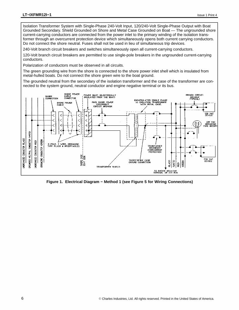
Isolation Transformer System with Single-Phase 240-Volt Input, 120/240-Volt Single-Phase Output with BoatGrounded Secondary. Shield Grounded on Shore and Metal Case Grounded on Boat — The ungrounded shorecurrent-carrying conductors are connected from the power inlet to the primary winding of the isolation trans-former through an overcurrent protection device which simultaneously opens both current carrying conductors.Do not connect the shore neutral. Fuses shall not be used in lieu of simultaneous trip devices.
240-Volt branch circuit breakers and switches simultaneously open all current-carrying conductors.
120-Volt branch circuit breakers are permitted to use single-pole breakers in the ungrounded current-carryingconductors.
Polarization of conductors must be observed in all circuits.
The green grounding wire from the shore is connected to the shore power inlet shell which is insulated frommetal-hulled boats. Do not connect the shore green wire to the boat ground.
The grounded neutral from the secondary of the isolation transformer and the case of the transformer are con-nected to the system ground, neutral conductor and engine negative terminal or its bus.
Figure 1. Electrical Diagram − Method 1 (see Figure 5 for Wiring Connections)
LT−IXFMR12I−1Issue 1 Print 4
7� Charles Industries, Ltd. All rights reserved. Printed in the United States of America.
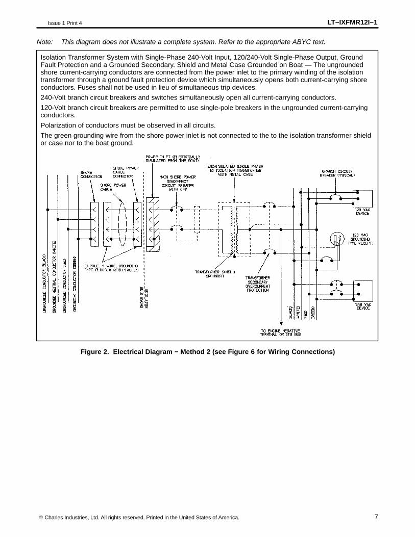
Note: This diagram does not illustrate a complete system. Refer to the appropriate ABYC text.
Isolation Transformer System with Single-Phase 240-Volt Input, 120/240-Volt Single-Phase Output, GroundFault Protection and a Grounded Secondary. Shield and Metal Case Grounded on Boat — The ungroundedshore current-carrying conductors are connected from the power inlet to the primary winding of the isolationtransformer through a ground fault protection device which simultaneously opens both current-carrying shoreconductors. Fuses shall not be used in lieu of simultaneous trip devices.
240-Volt branch circuit breakers and switches simultaneously open all current-carrying conductors.
120-Volt branch circuit breakers are permitted to use single-pole breakers in the ungrounded current-carryingconductors.
Polarization of conductors must be observed in all circuits.
The green grounding wire from the shore power inlet is not connected to the to the isolation transformer shieldor case nor to the boat ground.
Figure 2. Electrical Diagram − Method 2 (see Figure 6 for Wiring Connections)
LT−IXFMR12I−1 Issue 1 Print 4
8 � Charles Industries, Ltd. All rights reserved. Printed in the United States of America.
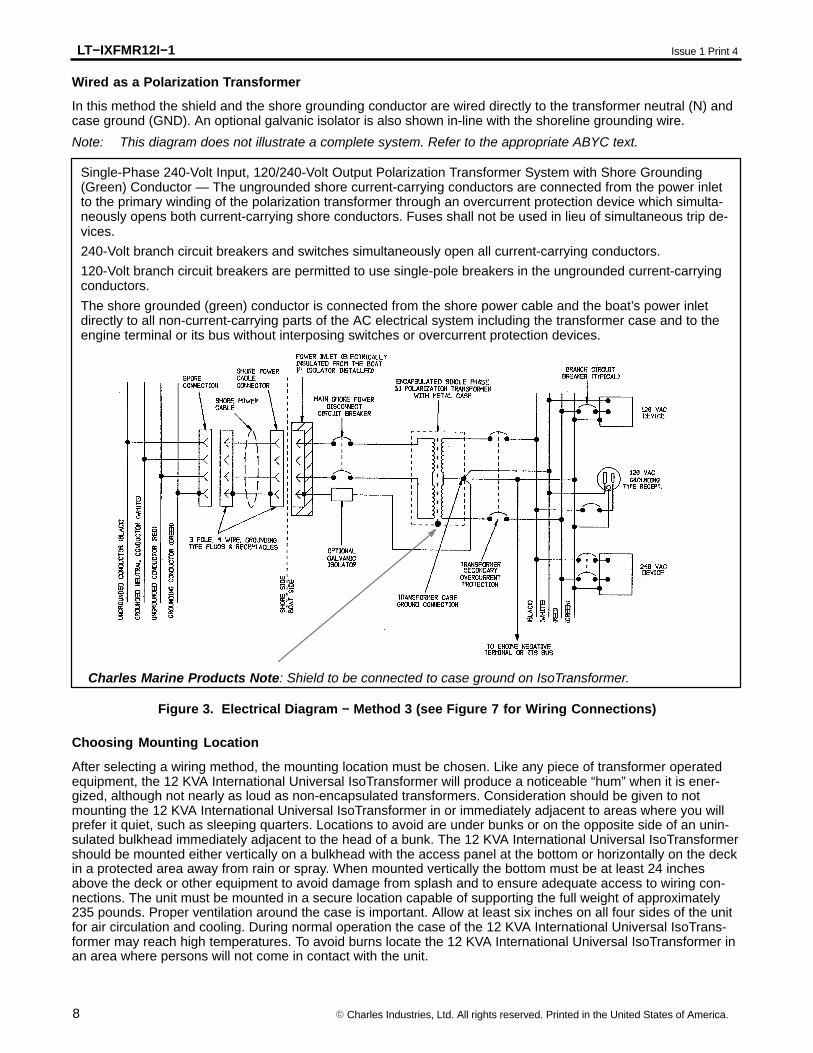
Wired as a Polarization Transformer
In this method the shield and the shore grounding conductor are wired directly to the transformer neutral (N) andcase ground (GND). An optional galvanic isolator is also shown in-line with the shoreline grounding wire.
Note: This diagram does not illustrate a complete system. Refer to the appropriate ABYC text.
Single-Phase 240-Volt Input, 120/240-Volt Output Polarization Transformer System with Shore Grounding(Green) Conductor — The ungrounded shore current-carrying conductors are connected from the power inletto the primary winding of the polarization transformer through an overcurrent protection device which simulta-neously opens both current-carrying shore conductors. Fuses shall not be used in lieu of simultaneous trip de-vices.
240-Volt branch circuit breakers and switches simultaneously open all current-carrying conductors.
120-Volt branch circuit breakers are permitted to use single-pole breakers in the ungrounded current-carryingconductors.
The shore grounded (green) conductor is connected from the shore power cable and the boat’s power inletdirectly to all non-current-carrying parts of the AC electrical system including the transformer case and to theengine terminal or its bus without interposing switches or overcurrent protection devices.
Charles Marine Products Note: Shield to be connected to case ground on IsoTransformer.
Figure 3. Electrical Diagram − Method 3 (see Figure 7 for Wiring Connections)
Choosing Mounting Location
After selecting a wiring method, the mounting location must be chosen. Like any piece of transformer operatedequipment, the 12 KVA International Universal IsoTransformer will produce a noticeable “hum” when it is ener-gized, although not nearly as loud as non-encapsulated transformers. Consideration should be given to notmounting the 12 KVA International Universal IsoTransformer in or immediately adjacent to areas where you willprefer it quiet, such as sleeping quarters. Locations to avoid are under bunks or on the opposite side of an unin-sulated bulkhead immediately adjacent to the head of a bunk. The 12 KVA International Universal IsoTransformershould be mounted either vertically on a bulkhead with the access panel at the bottom or horizontally on the deckin a protected area away from rain or spray. When mounted vertically the bottom must be at least 24 inchesabove the deck or other equipment to avoid damage from splash and to ensure adequate access to wiring con-nections. The unit must be mounted in a secure location capable of supporting the full weight of approximately235 pounds. Proper ventilation around the case is important. Allow at least six inches on all four sides of the unitfor air circulation and cooling. During normal operation the case of the 12 KVA International Universal IsoTrans-former may reach high temperatures. To avoid burns locate the 12 KVA International Universal IsoTransformer inan area where persons will not come in contact with the unit.
LT−IXFMR12I−1Issue 1 Print 4
9� Charles Industries, Ltd. All rights reserved. Printed in the United States of America.
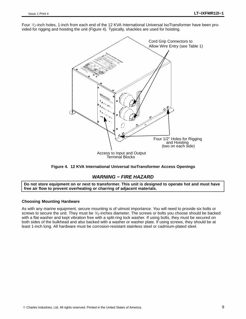
Four �/�-inch holes, 1-inch from each end of the 12 KVA International Universal IsoTransformer have been pro-vided for rigging and hoisting the unit (Figure 4). Typically, shackles are used for hoisting.
Cord Grip Connectors toAllow Wire Entry (see Table 1)
Four 1/2” Holes for Riggingand Hoisting
(two on each side)
Access to Input and Output Terminal Blocks
Figure 4. 12 KVA International Universal IsoTransformer Access Openings
Do not store equipment on or next to transformer. This unit is designed to operate hot and must havefree air flow to prevent overheating or charring of adjacent materials.
WARNING − FIRE HAZARD
Choosing Mounting Hardware
As with any marine equipment, secure mounting is of utmost importance. You will need to provide six bolts orscrews to secure the unit. They must be �/�-inches diameter. The screws or bolts you choose should be backedwith a flat washer and kept vibration free with a split-ring lock washer. If using bolts, they must be secured onboth sides of the bulkhead and also backed with a washer or washer plate. If using screws, they should be atleast 1-inch long. All hardware must be corrosion-resistant stainless steel or cadmium-plated steel.
LT−IXFMR12I−1 Issue 1 Print 4
10 � Charles Industries, Ltd. All rights reserved. Printed in the United States of America.
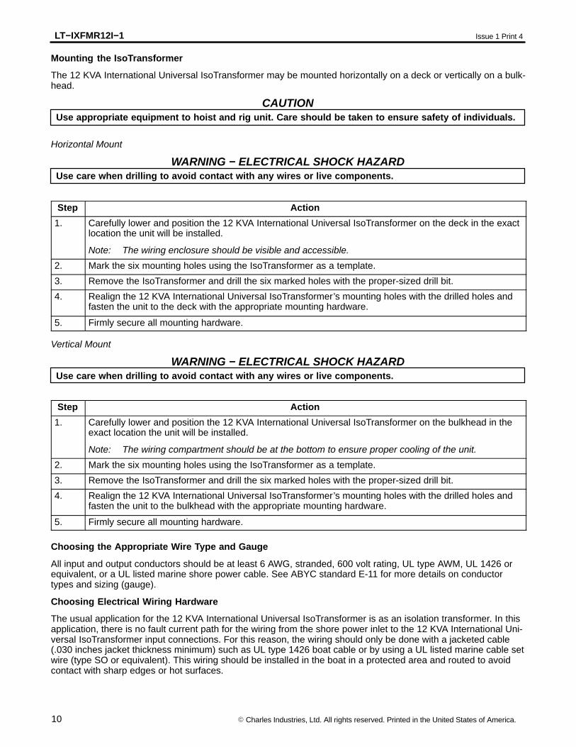
Mounting the IsoTransformer
The 12 KVA International Universal IsoTransformer may be mounted horizontally on a deck or vertically on a bulk-head.
Use appropriate equipment to hoist and rig unit. Care should be taken to ensure safety of individuals.CAUTION
Horizontal Mount
Use care when drilling to avoid contact with any wires or live components.WARNING − ELECTRICAL SHOCK HAZARD
Step Action
1. Carefully lower and position the 12 KVA International Universal IsoTransformer on the deck in the exactlocation the unit will be installed.
Note: The wiring enclosure should be visible and accessible.
2. Mark the six mounting holes using the IsoTransformer as a template.
3. Remove the IsoTransformer and drill the six marked holes with the proper-sized drill bit.
4. Realign the 12 KVA International Universal IsoTransformer’s mounting holes with the drilled holes andfasten the unit to the deck with the appropriate mounting hardware.
5. Firmly secure all mounting hardware.
Vertical Mount
Use care when drilling to avoid contact with any wires or live components.WARNING − ELECTRICAL SHOCK HAZARD
Step Action
1. Carefully lower and position the 12 KVA International Universal IsoTransformer on the bulkhead in theexact location the unit will be installed.
Note: The wiring compartment should be at the bottom to ensure proper cooling of the unit.
2. Mark the six mounting holes using the IsoTransformer as a template.
3. Remove the IsoTransformer and drill the six marked holes with the proper-sized drill bit.
4. Realign the 12 KVA International Universal IsoTransformer’s mounting holes with the drilled holes andfasten the unit to the bulkhead with the appropriate mounting hardware.
5. Firmly secure all mounting hardware.
Choosing the Appropriate Wire Type and Gauge
All input and output conductors should be at least 6 AWG, stranded, 600 volt rating, UL type AWM, UL 1426 orequivalent, or a UL listed marine shore power cable. See ABYC standard E-11 for more details on conductortypes and sizing (gauge).
Choosing Electrical Wiring Hardware
The usual application for the 12 KVA International Universal IsoTransformer is as an isolation transformer. In thisapplication, there is no fault current path for the wiring from the shore power inlet to the 12 KVA International Uni-versal IsoTransformer input connections. For this reason, the wiring should only be done with a jacketed cable(.030 inches jacket thickness minimum) such as UL type 1426 boat cable or by using a UL listed marine cable setwire (type SO or equivalent). This wiring should be installed in the boat in a protected area and routed to avoidcontact with sharp edges or hot surfaces.
LT−IXFMR12I−1Issue 1 Print 4
11� Charles Industries, Ltd. All rights reserved. Printed in the United States of America.
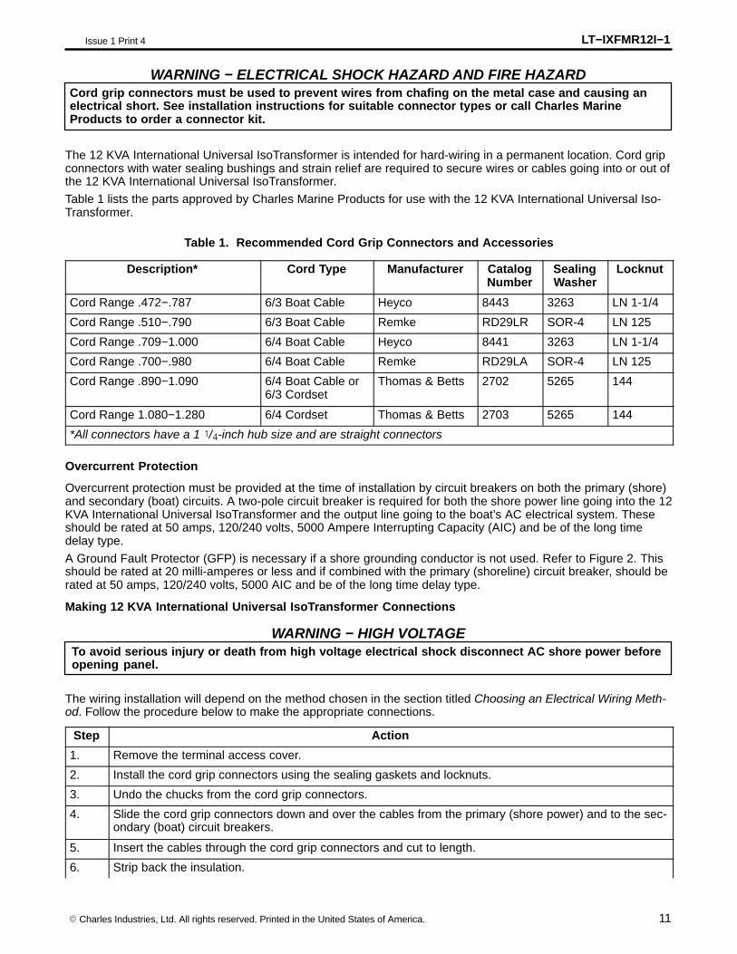
Cord grip connectors must be used to prevent wires from chafing on the metal case and causing anelectrical short. See installation instructions for suitable connector types or call Charles MarineProducts to order a connector kit.
WARNING − ELECTRICAL SHOCK HAZARD AND FIRE HAZARD
The 12 KVA International Universal IsoTransformer is intended for hard-wiring in a permanent location. Cord gripconnectors with water sealing bushings and strain relief are required to secure wires or cables going into or out ofthe 12 KVA International Universal IsoTransformer.
Table 1 lists the parts approved by Charles Marine Products for use with the 12 KVA International Universal Iso-Transformer.
Table 1. Recommended Cord Grip Connectors and Accessories
Description* Cord Type Manufacturer CatalogNumber
SealingWasher
Locknut
Cord Range .472−.787 6/3 Boat Cable Heyco 8443 3263 LN 1-1/4
Cord Range .510−.790 6/3 Boat Cable Remke RD29LR SOR-4 LN 125
Cord Range .709−1.000 6/4 Boat Cable Heyco 8441 3263 LN 1-1/4
Cord Range .700−.980 6/4 Boat Cable Remke RD29LA SOR-4 LN 125
Cord Range .890−1.090 6/4 Boat Cable or6/3 Cordset
Thomas & Betts 2702 5265 144
Cord Range 1.080−1.280 6/4 Cordset Thomas & Betts 2703 5265 144
*All connectors have a 1 �/�-inch hub size and are straight connectors
Overcurrent Protection
Overcurrent protection must be provided at the time of installation by circuit breakers on both the primary (shore)and secondary (boat) circuits. A two-pole circuit breaker is required for both the shore power line going into the 12KVA International Universal IsoTransformer and the output line going to the boat’s AC electrical system. Theseshould be rated at 50 amps, 120/240 volts, 5000 Ampere Interrupting Capacity (AIC) and be of the long timedelay type.
A Ground Fault Protector (GFP) is necessary if a shore grounding conductor is not used. Refer to Figure 2. Thisshould be rated at 20 milli-amperes or less and if combined with the primary (shoreline) circuit breaker, should berated at 50 amps, 120/240 volts, 5000 AIC and be of the long time delay type.
Making 12 KVA International Universal IsoTransformer Connections
To avoid serious injury or death from high voltage electrical shock disconnect AC shore power beforeopening panel.
WARNING − HIGH VOLTAGE
The wiring installation will depend on the method chosen in the section titled Choosing an Electrical Wiring Meth-od. Follow the procedure below to make the appropriate connections.
Step Action
1. Remove the terminal access cover.
2. Install the cord grip connectors using the sealing gaskets and locknuts.
3. Undo the chucks from the cord grip connectors.
4. Slide the cord grip connectors down and over the cables from the primary (shore power) and to the sec-ondary (boat) circuit breakers.
5. Insert the cables through the cord grip connectors and cut to length.
6. Strip back the insulation.
LT−IXFMR12I−1 Issue 1 Print 4
12 � Charles Industries, Ltd. All rights reserved. Printed in the United States of America.
Step Action
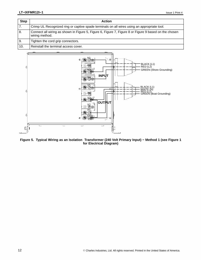
7. Crimp UL Recognized ring or captive spade terminals on all wires using an appropriate tool.
8. Connect all wiring as shown in Figure 5, Figure 6, Figure 7, Figure 8 or Figure 9 based on the chosenwiring method.
9. Tighten the cord grip connectors.
10. Reinstall the terminal access cover.
SH
OUTPUT
INPUT
H3
H2
H1
X4
X3
X2
X5
BLACK (L1)RED (L2)GREEN (Shore Grounding)
BLACK (L1)WHITE (N)RED (L2)GREEN (Boat Grounding)
GND
X1
Figure 5. Typical Wiring as an Isolation Transformer (240 Volt Primary Input) − Method 1 (see Figure 1for Electrical Diagram)
LT−IXFMR12I−1Issue 1 Print 4
13� Charles Industries, Ltd. All rights reserved. Printed in the United States of America.
SH
OUTPUT
INPUT
H3
H2
H1
X4
X3
X2
X5
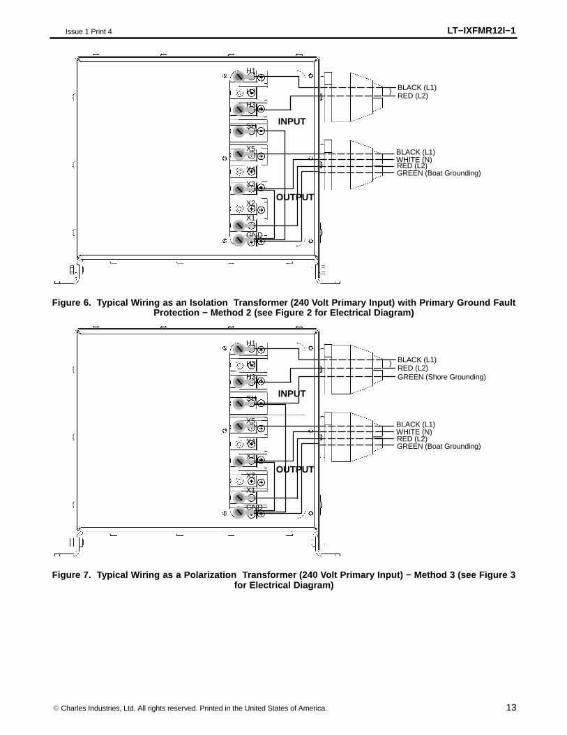
BLACK (L1)RED (L2)
)
BLACK (L1)WHITE (N)RED (L2)GREEN (Boat Grounding)
GND
X1
Figure 6. Typical Wiring as an Isolation Transformer (240 Volt Primary Input) with Primary Ground FaultProtection − Method 2 (see Figure 2 for Electrical Diagram)
SH
OUTPUT
INPUT
H3
H2
H1
X4
X3
X2
X5
BLACK (L1)RED (L2)
)
GREEN (Shore Grounding)
BLACK (L1)WHITE (N)RED (L2)GREEN (Boat Grounding)
GND
X1
Figure 7. Typical Wiring as a Polarization Transformer (240 Volt Primary Input) − Method 3 (see Figure 3for Electrical Diagram)
LT−IXFMR12I−1 Issue 1 Print 4
14 � Charles Industries, Ltd. All rights reserved. Printed in the United States of America.
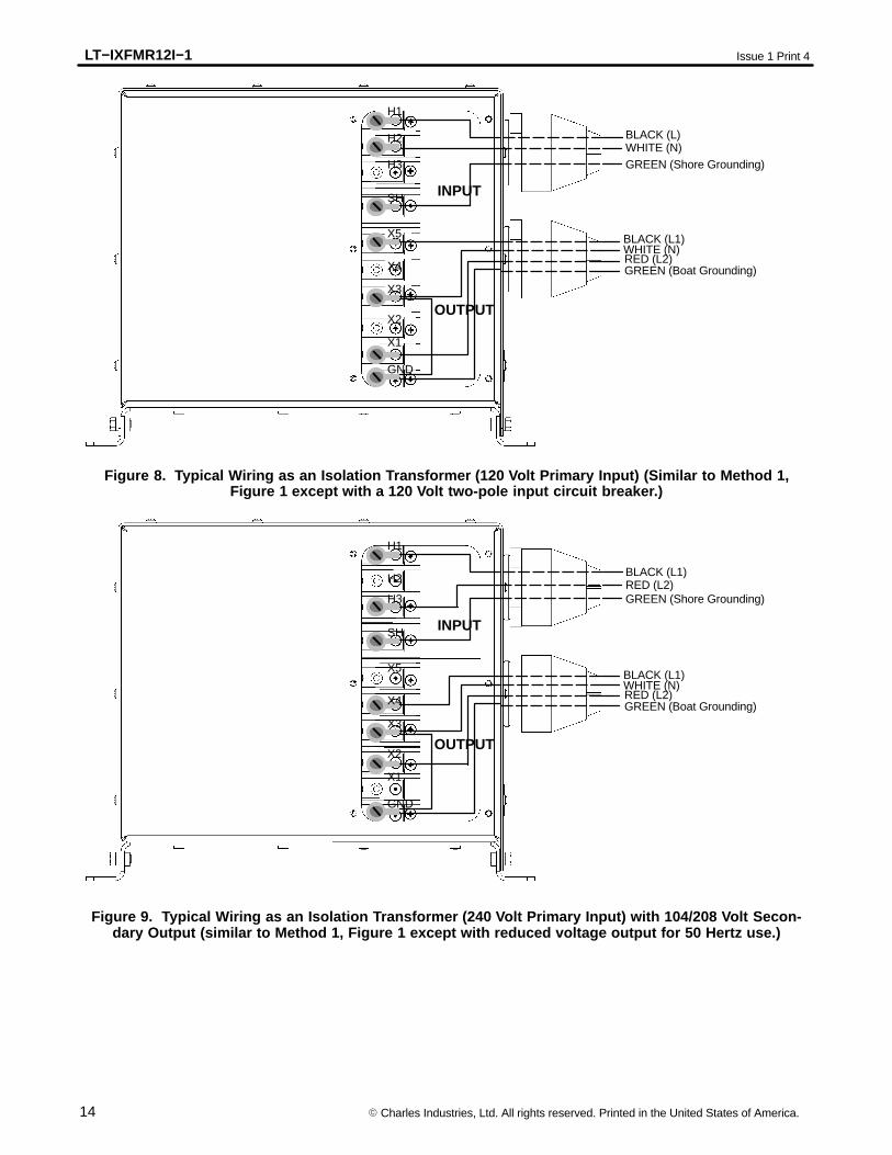
SH
OUTPUT
INPUT
H3
H2
H1
X4
X3
X2
X5
BLACK (L)WHITE (N)GREEN (Shore Grounding)
BLACK (L1)WHITE (N)RED (L2)GREEN (Boat Grounding)
GND
X1
Figure 8. Typical Wiring as an Isolation Transformer (120 Volt Primary Input) (Similar to Method 1,Figure 1 except with a 120 Volt two-pole input circuit breaker.)
SH
OUTPUT
INPUT
H3
H2
H1
X4
X3
X2
X5
BLACK (L1)RED (L2)GREEN (Shore Grounding)
BLACK (L1)WHITE (N)RED (L2)GREEN (Boat Grounding)
GND
X1
Figure 9. Typical Wiring as an Isolation Transformer (240 Volt Primary Input) with 104/208 Volt Secon-dary Output (similar to Method 1, Figure 1 except with reduced voltage output for 50 Hertz use.)
LT−IXFMR12I−1Issue 1 Print 4
15� Charles Industries, Ltd. All rights reserved. Printed in the United States of America.
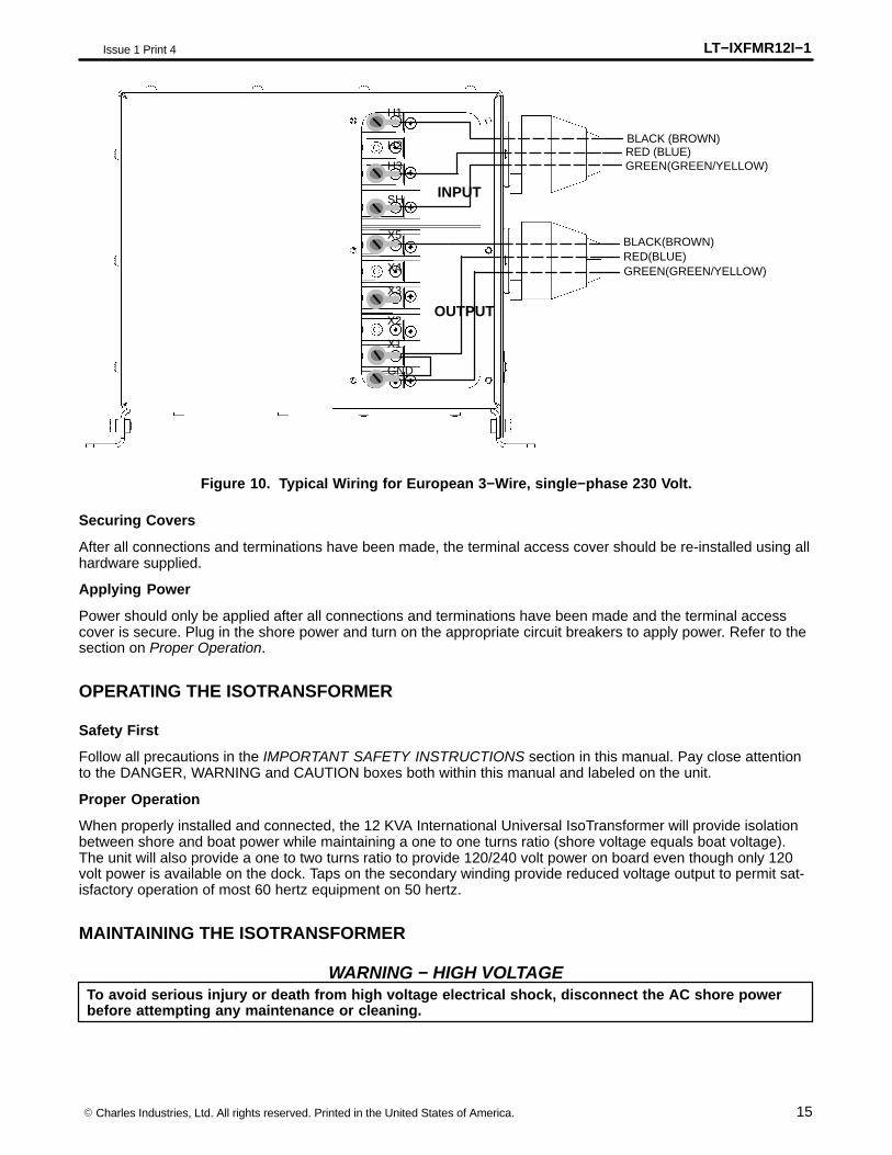
SH
OUTPUT
INPUT
H3
H2
H1
X4
X3
X2
X5
RED (BLUE)GREEN(GREEN/YELLOW)
BLACK(BROWN)RED(BLUE)GREEN(GREEN/YELLOW)
GND
X1
BLACK (BROWN)
Figure 10. Typical Wiring for European 3−Wire, single−phase 230 Volt.
Securing Covers
After all connections and terminations have been made, the terminal access cover should be re-installed using allhardware supplied.
Applying Power
Power should only be applied after all connections and terminations have been made and the terminal accesscover is secure. Plug in the shore power and turn on the appropriate circuit breakers to apply power. Refer to thesection on Proper Operation.
OPERATING THE ISOTRANSFORMER
Safety First
Follow all precautions in the IMPORTANT SAFETY INSTRUCTIONS section in this manual. Pay close attentionto the DANGER, WARNING and CAUTION boxes both within this manual and labeled on the unit.
Proper Operation
When properly installed and connected, the 12 KVA International Universal IsoTransformer will provide isolationbetween shore and boat power while maintaining a one to one turns ratio (shore voltage equals boat voltage).The unit will also provide a one to two turns ratio to provide 120/240 volt power on board even though only 120volt power is available on the dock. Taps on the secondary winding provide reduced voltage output to permit sat-isfactory operation of most 60 hertz equipment on 50 hertz.
MAINTAINING THE ISOTRANSFORMER
To avoid serious injury or death from high voltage electrical shock, disconnect the AC shore powerbefore attempting any maintenance or cleaning.
WARNING − HIGH VOLTAGE
LT−IXFMR12I−1 Issue 1 Print 4
16 � Charles Industries, Ltd. All rights reserved. Printed in the United States of America.
No adjustment or maintenance is required for the 12 KVA International Universal IsoTransformer other than peri-odic cleaning of the outside cabinet with a dry cloth and inspecting all connections for tightness and corrosion bya qualified service person.
TROUBLESHOOTING
If there is a problem with the 12 KVA International Universal IsoTransformer, first check that all connections areaccurate and secure, and retest. If all connections are good, contact Charles Marine Products for technical assis-tance.
WARRANTY & CUSTOMER SERVICE
Warranty
The CHARLES Marine & Industrial Group warrants the unit will be free from defects in materials and workman-ship that cause mechanical failure for one (1) year, as set forth in the Limited Warranty. Notice of any alleged de-fect in material or workmanship must be provided within thirty (30) days of discovering the problem, and within thewarranty period. Follow the procedure outlined below to obtain warranty service.
Service Center and Repair Correspondence
Note: Do not attempt to service the unit. Contact the Service Center.
To contact the Service Center via telephone directly:800−830−6523 (Toll Free)217−932−2317 (Voice)217−932−2473 (FAX)
Call to obtain a Returned Materials Authorization (RMA) number prior to returning any unit to Charles Industries.
Return the unit for repairs to the Service & Repair Center address below:Charles Industries, Ltd.Marine & Industrial Group503 NE 15th StreetCasey, IL 62420-2054USA
Correspondence can be sent to Corporate Headquarters via the address below:
Note: Do not return the unit to this address.
Charles Industries, Ltd.Marine & Industrial Group5600 Apollo DriveRolling Meadows, IL 60008-4049USA847−806−6300www.charlesindustries.com
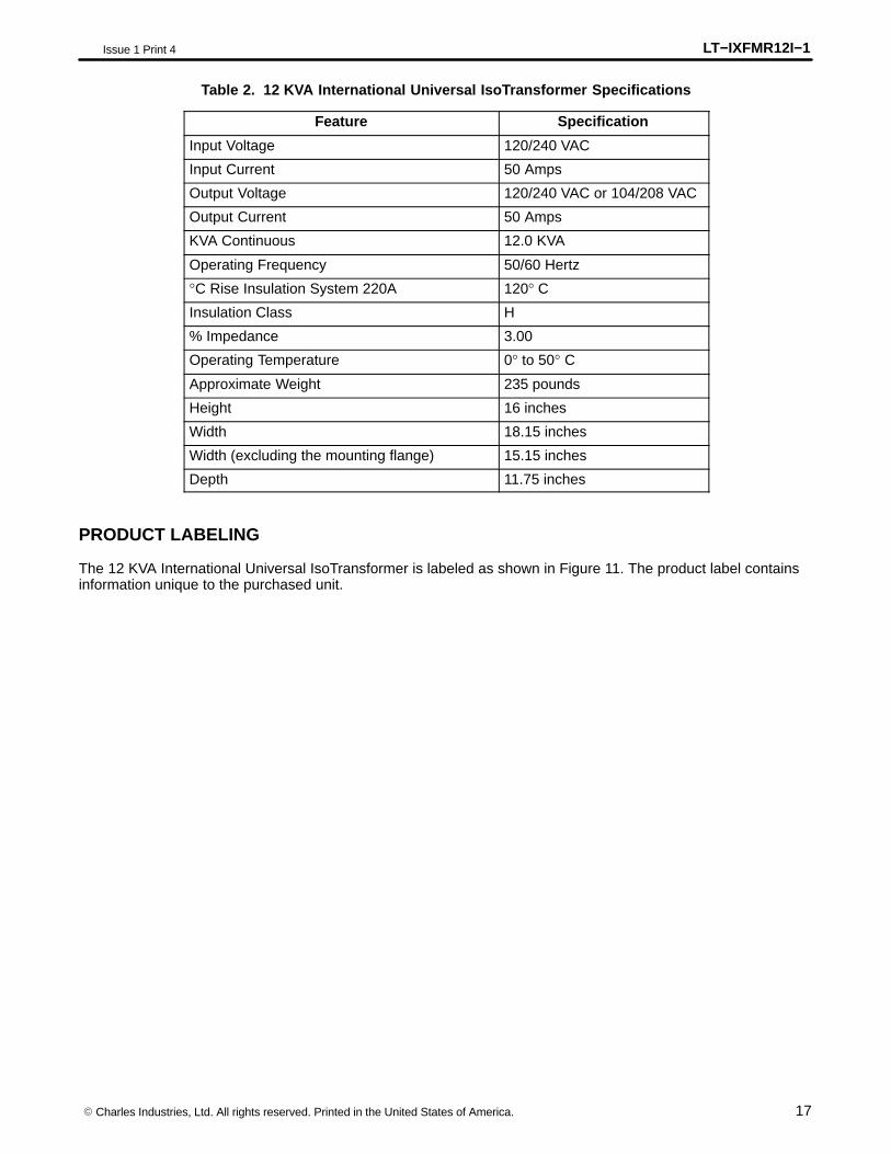
SPECIFICATIONS
The specifications for the 12 KVA International Universal IsoTransformer are listed in Table 2.
LT−IXFMR12I−1Issue 1 Print 4
17� Charles Industries, Ltd. All rights reserved. Printed in the United States of America.
Table 2. 12 KVA International Universal IsoTransformer Specifications
Feature Specification
Input Voltage 120/240 VAC
Input Current 50 Amps
Output Voltage 120/240 VAC or 104/208 VAC
Output Current 50 Amps
KVA Continuous 12.0 KVA
Operating Frequency 50/60 Hertz
°C Rise Insulation System 220A 120° C
Insulation Class H
% Impedance 3.00
Operating Temperature 0° to 50° C
Approximate Weight 235 pounds
Height 16 inches
Width 18.15 inches
Width (excluding the mounting flange) 15.15 inches
Depth 11.75 inches
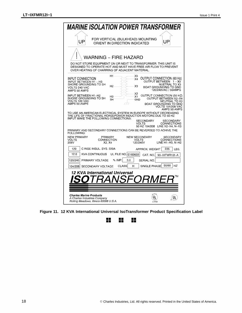
PRODUCT LABELING
The 12 KVA International Universal IsoTransformer is labeled as shown in Figure 11. The product label containsinformation unique to the purchased unit.
LT−IXFMR12I−1 Issue 1 Print 4
18 � Charles Industries, Ltd. All rights reserved. Printed in the United States of America.
Figure 11. 12 KVA International Universal IsoTransformer Product Specification Label
� � �