Embed Size (px)
Citation preview

0
HUAWEI TECHNOLOGIES CO., LTD.
UPS2000-G-(1 kVA-3 kVA)
Quick Guide
Issue: 05
Date: 2017-07-21

1
UPS Model Represented By Weight Dimensions (H x W x D)
UPS2000-G-1KRTS1 K-standard model-rack
mounted-IEC10.7 kg 88 mm x 438 mm x 310 mm
UPS2000-G-1KRTL1 K-long backup time
model-rack mounted-IEC5.9 kg 88 mm x 438 mm x 310 mm
UPS2000-G-2KRTS2 K-standard model-rack
mounted-IEC18.5 kg 88 mm x 438 mm x 410 mm
UPS2000-G-2KRTL2 K-long backup time
model-rack mounted-IEC8.6 kg 88 mm x 438 mm x 410 mm
UPS2000-G-3KRTS3 K-standard model-rack
mounted-IEC27. 9 kg 88 mm x 438 mm x 630 mm
UPS2000-G-3KRTL3 K-long backup time
model-rack mounted-IEC9.2 kg 88 mm x 438 mm x 410 mm
1 Introduction
UPS2000-G-1KRTS
UPS2000-G-1KRTL
UPS2000-G-2KRTS
UPS2000-G-2KRTL
(1) Mains input socket
(C14)
(2) Input circuit breaker
(3) Universal serial bus
(USB) port (security
protection mechanism
supported)
(4) RS232 port
(5) Optional card slot
(6) Output socket (C13)
(7) External battery
connector (only for
long backup time
models)
Copyright © Huawei Technologies Co., Ltd. 2017. All rights reserved.
(1) Mains input socket
(C14)
(2) Input circuit breaker
(3) USB port (security
protection mechanism
supported)
(4) RS232 port
(5) Optional card slot
(6) Output socket (C13)
(7) External battery
connector (only for
long backup time
models)

2
UPS2000-G-3KRTS
UPS2000-G-3KRTL
(1) Mains input socket
(C20)
(2) Input circuit breaker
(3) USB port (security
protection
mechanism
supported)
(4) RS232 port
(5) Optional card slot
(6) Output socket (C13)
(7) Output socket (C19)
(8) External battery
connector (only for
long backup time
models)
UPS2000-G Rack-mounting InstallationScenario 1
1. Before installation, read the UPS2000-G-(1 kVA-3 kVA) User Manual to get familiar with UPS
information and safety precautions. UPS is short for uninterruptible power system.
2. Use fully insulated tools during installation and operations.
3. Only engineers certified by the manufacturer or its agents are allowed to perform UPS
installation, commissioning and maintenance. Otherwise, personal injury or equipment damage
may occur, and the resulting UPS faults are beyond warranty scope.
1. Install mounting brackets on UPS.
2. Install guide on the Cabinet. Then place the UPS on the guide rails. For details about how to
install guide and UPS on the cabinet, see the UPS2000-G-(1 kVA-3 kVA) Rail Assembly Quick
Installation Guide.
NOTICE
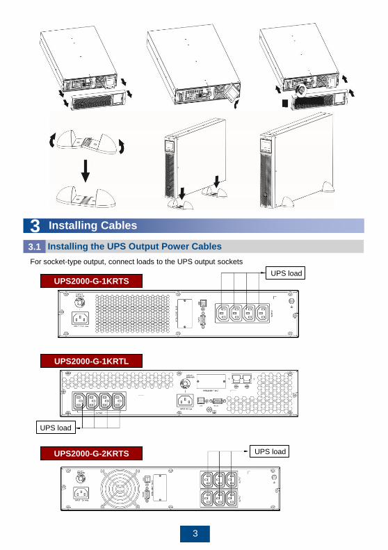
2 Installing a Single UPS
UPS2000-G Tower-mounting InstallationScenario 2
To tower-mount a UPS, perform the following steps:
1. Remove the UPS front panel.
2. Rotate the control panel 90 degrees clockwise.
3. Rotate the logo 90 degrees clockwise on the front panel. Reinstall the front panel.
4. Assemble support bases. The minimum distance between two support bases should be 150 mm.
5. Place UPS on the support bases in sequence.
6. Adjust the UPS and the support bases to be horizontally.
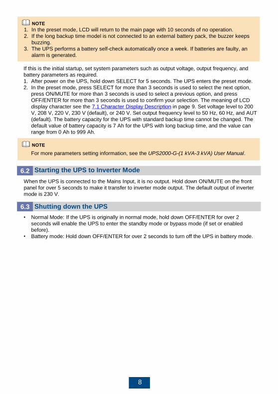
UPS loadUPS2000-G-1KRTS
UPS load
UPS2000-G-1KRTL
UPS loadUPS2000-G-2KRTS
3
3 Installing Cables
For socket-type output, connect loads to the UPS output sockets
Installing the UPS Output Power Cables3.1

4
Connect the battery cable delivered with the long backup time model to an external battery pack.
(This step is optional for the long backup time model. The standard model contains batteries and
provides no battery port.)
The installation method for 1 kVA UPS, 2 kVA UPS, and 3 kVA UPS is the same. The figures
below are based on the 3 kVA UPS.
For details, see the UPS2000-G-(1 kVA-3 kVA) Battery Pack Quick Installation Guide.
Installing the UPS Battery Cable (Only for UPS with Long Backup Time)3.2
UPS load
UPS2000-G-3KRTS
UPS2000-G-3KRTL
UPS load
UPS2000-G-2KRTL
UPS load
1. If the 1 kVA UPS with long backup time needs to connect to external battery strings, each
battery string must consist of three 12 V batteries connected in series. If the 2 kVA UPS with
long backup time needs to connect to external battery strings, each battery string must consist
of six 12 V batteries connected in series. If the 3 kVA UPS with long backup time needs to
connect to external battery strings, each battery string must consist of eight 12 V batteries
connected in series.
2. The UPS with long backup time provides a charge current of 4 A and the current is not
configurable. If the UPS needs to connect to battery packs or battery strings, the total battery
capacity must exceed 18 Ah. Otherwise, batteries may be damaged. If the capacity of external
battery packs or battery strings to be connected exceeds 40 Ah, it is recommended that an
external charger be purchased to increase the charge current. If an external chargers is not
purchased, the charge time will be long.
3. The battery pack (ESS-36V12-9*2AHBPVBB01) for 1 kVA UPS with long backup time contain
two group battery strings. The battery pack (ESS-72V12-9AHBPVBB01) for 2 kVA UPS with
long backup time only contain one group battery strings. The battery pack (ESS-96V12-
9AHBPVBB02) for 3 kVA UPS with long backup time only contain one group battery strings.
4. The 1 kVA UPS with long backup time is allowed a maximum of two battery packs (ESS-36V12-
9*2AHBPVBB01) in parallel. The 2 kVA UPS with long backup time is allowed a maximum of
four battery packs (ESS-72V12-9AHBPVBB01) in parallel. The 3 kVA UPS with long backup
time is allowed a maximum of four battery packs (ESS-96V12-9AHBPVBB02) in parallel.

5
Connect the UPS to the RS232 or USB port on a PC. Then you can monitor the UPS status using
the PC as long as you have installed the monitoring software. The installation method for 1 kVA
UPS, 2 kVA UPS, and 3 kVA UPS is the same. The figures below based on the 3 kVA UPS.
Installing the UPS Communication Cable3.3
1. The USB channel supports a serial data communications protocol between the UPS and the PC.
2. If you connect a DB9 connector to the RS232 port, the UPS can communicate with the PC over
serial data.
3. The UPS support either USB or RS232.
4. To monitor the UPS over a PC, also need to install the monitoring software iManager NetEco
1000U. For details about how to install and use the iManager NetEco 1000U, see the iManager
NetEco 1000U User Manual. The software and the user manual are available at
http://support.huawei.com or http://support.huawei.com/enterprise.
PC
PC
UPS2000-G-3KRTS
PC PC
UPS2000-G-3KRTL
Battery packUPS2000-G-3KRTL
Installing the UPS Input Cable3.4
Mains input
UPS2000-G-1KRTS
Take out input power cable from the fitting bag, and connect mains input power cable to the UPS.
UPS2000-G-1KRTL
Mains input

6
UPS2000-G-3KRTS
Mains input
For the installation procedure, see the RMS-SNMP01B SNMP Card User Manual, RMS-RELAY01B
User Manual, RMS-MODBUS01B User Manual. The installation method for 1 kVA, 2 kVA UPS, and
3 kVA UPS is the same. The figures below are based on the 3 kVA UPS.
4 Installing the Optional Card to the UPS
No. Item Acceptance Criterion
1 Cable routing Cable routing meets engineering requirements.
2 Cable connections Power cables and battery cables are tightened to
specified torques using a torque wrench,
connected correctly, and free of damage.
3 Cable connections for USB ports and
network ports
Cables to USB ports and network ports are
connected correctly and securely.
4 Labels Labels are neatly attached to both ends of each
cable, and the information on the labels is concise
and understandable.
5 Ground cable connection and
upstream circuit breaker for the UPS
The ground cable is securely connected to the
ground bar in the equipment room. An upstream
circuit breaker of proper specifications is installed
on the UPS input end.
6 Distances between cable ties Distances between cable ties are the same, and
no burr exists.
7 Operating environment Clean the conductive air and other sundries.
Verifying the Installation5Optional Card
UPS2000-G-3KRTS UPS2000-G-3KRTL
Optional Card
UPS2000-G-3KRTL
Mains input
Mains input
UPS2000-G-2KRTS UPS2000-G-2KRTL
Mains input

7
Operations6
ON/MUTE SELECT OFF/ENTER
Setting Key UPS Parameters 6.1
1. The 1 kVA UPS with standard backup time have two built-in batteries, the 2 kVA UPS with
standard backup time have four built-in batteries, the 3 kVA UPS with standard backup time
have six built-in batteries.
2. If the 1 kVA UPS with long backup time needs to connect to external battery strings, each
battery string must consist of three 12 V batteries connected in series. If the 2 kVA UPS with
long backup time needs to connect to external battery strings, each battery string must consist
of six 12 V batteries connected in series. If the 3 kVA UPS with long backup time needs to
connect to external battery strings, each battery string must consist of eight 12 V batteries
connected in series.
3. The UPS with long backup time provides a charge current of 4 A and the current is not
configurable. If the UPS needs to connect to battery packs or battery strings, the total battery
capacity must exceed 18 Ah. Otherwise, batteries may be damaged. If the capacity of external
battery packs or battery strings to be connected exceeds 40 Ah, it is recommended that an
external charger be purchased to increase the charge current. If an external charger is not
purchased, the charge time will be long.
4. For the UPS with standard backup time, the battery capacity has a fixed value of 9 Ah and the
charge current has a fixed value of 1 A. Set the battery capacity to the total capacity of all
batteries actually connected. Set the battery capacity for the long backup time model based
on site requirements. The default value is 7 Ah. For example, if eight batteries (9 Ah, 12 V) are
connected in series to form a battery string, and two of such battery strings are connected in
parallel and then to the UPS, set battery capacity to 18 Ah (9 Ah + 9 Ah). This parameter
affects the backup time calculation. Incorrect setting will cause incorrect display of the backup
time on the LCD.
5. When the battery pack/batteries connect to the Long back-up UPS for the first time, you must
do a battery self-check manually, in order to confirm the battery connection is normal. The
method is: hold down ON/MUTE on the front panel for 5 seconds, then the UPS transfer to
battery mode to do a shallow discharge test, after 10 seconds it automatically back to line
mode.
6. Charge the batteries used for the first time for 5 hours. Otherwise, the battery discharge time
will decrease.
NOTICE
8
If this is the initial startup, set system parameters such as output voltage, output frequency, and
battery parameters as required.
1. After power on the UPS, hold down SELECT for 5 seconds. The UPS enters the preset mode.
2. In the preset mode, press SELECT for more than 3 seconds is used to select the next option,
press ON/MUTE for more than 3 seconds is used to select a previous option, and press
OFF/ENTER for more than 3 seconds is used to confirm your selection. The meaning of LCD
display character see the 7.1 Character Display Description in page 9. Set voltage level to 200
V, 208 V, 220 V, 230 V (default), or 240 V. Set output frequency level to 50 Hz, 60 Hz, and AUT
(default). The battery capacity for the UPS with standard backup time cannot be changed. The
default value of battery capacity is 7 Ah for the UPS with long backup time, and the value can
range from 0 Ah to 999 Ah.
For more parameters setting information, see the UPS2000-G-(1 kVA-3 kVA) User Manual.
1. In the preset mode, LCD will return to the main page with 10 seconds of no operation.
2. If the long backup time model is not connected to an external battery pack, the buzzer keeps
buzzing.
3. The UPS performs a battery self-check automatically once a week. If batteries are faulty, an
alarm is generated.
Starting the UPS to Inverter Mode6.2
When the UPS is connected to the Mains Input, it is no output. Hold down ON/MUTE on the front
panel for over 5 seconds to make it transfer to inverter mode output. The default output of inverter
mode is 230 V.
Shutting down the UPS6.3
• Normal Mode: If the UPS is originally in normal mode, hold down OFF/ENTER for over 2
seconds will enable the UPS to enter the standby mode or bypass mode (if set or enabled
before).
• Battery mode: Hold down OFF/ENTER for over 2 seconds to turn off the UPS in battery mode.

9
Acronym Display Description Acronym Display Description
ENA Enable FRE Frequency
DIS Disable BVU Bypass overvoltage
ESC Escape BVL Bypass
undervoltage
CF Frequency
conversion
CAP Capacity
TP Temperature DT Discharge time
CH Charging ECO ECO mode
FU Bypass frequency
unstable
VU High voltage
EE EEPROM error VL Low voltage
VOT VoltageAUT
Constant-frequency
mode
BUZ Buzzer off AST Automatic startup
Alarm type Buzzer alarm tone
Battery mode Beeps once every 4 seconds.
Minor alarm Beeps once every second.
Overload Beeps twice every second.
Critical alarm Buzzes continuously.
Bypass mode Beeps once every 10 seconds.
7 FAQ
Character Display Description7.1
Buzzer Alarm Tone Description7.2
10
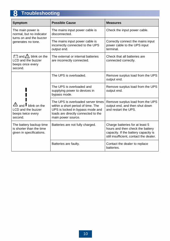
Symptom Possible Cause Measures
The main power is
normal, but no indicator
turns on and the buzzer
generates no tone.
The mains input power cable is
disconnected.
Check the input power cable.
The mains input power cable is
incorrectly connected to the UPS
output end.
Correctly connect the mains input
power cable to the UPS input
terminal.
and blink on the
LCD and the buzzer
beeps once every
second.
The external or internal batteries
are incorrectly connected.
Check that all batteries are
connected correctly.
and blink on the
LCD and the buzzer
beeps twice every
second.
The UPS is overloaded. Remove surplus load from the UPS
output end.
The UPS is overloaded and
supplying power to devices in
bypass mode.
Remove surplus load from the UPS
output end.
The UPS is overloaded server times
within a short period of time. The
UPS is locked in bypass mode and
loads are directly connected to the
main power source.
Remove surplus load from the UPS
output end, and then shut down
and restart the UPS.
The battery backup time
is shorter than the time
given in specifications.
Batteries are not fully charged. Charge batteries for at least 5
hours and then check the battery
capacity. If the battery capacity is
still insufficient, contact the dealer.
Batteries are faulty. Contact the dealer to replace
batteries.
8 Troubleshooting

11
For more alarm handling, see the UPS2000-G-(1 kVA-3 kVA) User Manual.
Ala
rm
ID
Ala
rm
Cau
se
ID
Alarm
Name
Alarm
Sever
ity
Alarm
Clear
Mode
Trigger
Condition
Impact on
the System
Repair Proposal
10 1 Bypass
voltage
abnorm
al
Minor This
alarm is
automatic
ally
cleared.
The
bypass
voltage is
outside the
scope.
The UPS
remains in the
current state.
If the UPS
works in
bypass mode,
it transfers to
standby mode
and has no
output.
Possible causes:
The bypass input
voltage is
abnormal.
Measures: Check
whether the bypass
input voltage
exceeds the
configured range. If
yes, change the
range or wait until
the bypass input
recovers.
2 Bypass
frequen
cy
abnorm
al
Minor This
alarm is
automatic
ally
cleared.
The
bypass
frequency
is outside
the bypass
frequency
range.
The UPS
remains in the
current state.
If the UPS
works in
bypass mode,
it transfers to
standby mode
and has no
output.
Possible causes:
The bypass input
frequency is
abnormal.
Measures: Check
whether the bypass
input frequency
exceeds the
configured range. If
yes, change the
range or wait until
the bypass input
recovers.
22 1 Battery
disconn
ected
Minor This
alarm is
automatic
ally
cleared.
Batteries
are not
connected,
connected
improperly,
or
damaged.
The power
supply from
the UPS is not
affected.
• Possible cause:
No batteries are
connected.
Measure:
Connect
batteries.
• Possible cause:
The batteries
are in poor
contact.
Measure: Check
the battery
cable
connection. If
battery cables
are loose,
connect them
securely.
9 Alarm Handling

12
Ala
rm
ID
Ala
rm
Cau
se
ID
Alarm
Name
Alarm
Severit
y
Alarm
Clear
Mode
Trigger
Conditi
on
Impact on the
System
Repair Proposal
25 1 Battery
overvol
tage
Critical This
alarm
must
be
manu
ally
cleare
d.
The
voltage
of each
battery
exceeds
15 V
(when
the UPS
is
started).
This alarm is
generated because
there are more
batteries than
required. The
impact is as follows:
• If battery packs
are connected
before the
startup, the UPS
fails to start.
• If battery packs
are connected
during the
running of the
UPS, the UPS
transfers to
bypass mode.
• Possible cause:
The actual
number of
batteries does not
meet
requirements.
Measure: Check
that the actual
number of
batteries meets
requirements.
• Possible cause:
The charger is
abnormal.
Measure: Check
that the charger
voltage is normal
immediately after
the batteries are
disconnected.Minor This
alarm
is
autom
aticall
y
cleare
d after
the
UPS
transf
ers to
batter
y
mode.
The
voltage
of each
battery
exceeds
14.7 V.
The UPS
automatically
transfers to battery
mode. When the
battery
undervoltage alarm
is generated, the
UPS automatically
transfers to normal
mode and starts the
charger for
charging.
26 1 Battery
underv
oltage
Critical This
alarm
must
be
manu
ally
cleare
d.
The
voltage
of each
battery
is lower
than 5 V
(when
the UPS
is
started).
This alarm is
generated because
there are more
batteries than
required. The
impact is as follows:
• If battery packs
are connected
before the
startup, the UPS
fails to start.
• If battery packs
are connected
during the
running of the
UPS, the UPS
transfers to
bypass mode.
• Possible cause:
The actual
number of
batteries does not
meet
requirements.
Measure: Check
that the actual
number of
batteries meets
requirements.
• Possible cause:
The mains is
abnormal, and the
batteries are
overdischarged.
Measure: Connect
to the mains in
non-battery test
state.

13
Ala
rm
ID
Ala
rm
Cau
se
ID
Alarm
Name
Alar
m
Seve
rity
Alarm
Clear
Mode
Trigger
Condition
Impact on the
System
Repair Proposal
26 1 Battery
underv
oltage
Minor This
alarm
is
autom
aticall
y
cleare
d.
The voltage of
each battery is
lower than
11.28 V.
The power supply
from the UPS is
not affected.
• Possible cause:
The actual
number of
batteries does
not meet
requirements.
Measure: Check
that the actual
number of
batteries meets
requirements.
• Possible cause:
The mains is
abnormal, and
the batteries are
overdischarged.
Measure:
Connect to the
mains in non-
battery test
state.
29 1 Battery
requirin
g
mainte
nance
Minor This
alarm
is
autom
aticall
y
cleare
d.
The battery
voltage is
lower than the
battery
replacement
voltage (11 V)
when batteries
are in self-
check mode.
The power supply
from the UPS is
not affected.
• Possible cause:
The actual
number of
batteries does
not meet
requirements.
Measure: Check
that the actual
number of
batteries meets
requirements.
• Possible cause:
The battery is
damaged.
Measure:
Contact the
dealer or
Huawei
technical
support to
replace
batteries.
Minor This
alarm
is
autom
aticall
y
cleare
d.
The voltage of
each battery is
lower than 5
V, or is higher
than 15 V
(when the
UPS is not
started).
The UPS remains
in the current
state and cannot
start.

14
Ala
rm
ID
Ala
rm
Cau
se
ID
Alarm
Name
Alar
m
Seve
rity
Alarm
Clear
Mode
Trigger
Condition
Impact on the
System
Repair Proposal
42 17 Internal
fault
Critic
al
This
alarm
must
be
manu
ally
cleare
d.
The bus
voltage is
higher than
450 V.
If this alarm is
generated during
the running of the
UPS, the UPS
transfers to bypass
mode.
• Possible
cause: The
mains has
experienced a
transient high
voltage.
Measure:
Rectify the
fault and
restart the
UPS.
• Possible
cause: The
output
supplies
power to
special loads
such as the
inductive and
rectification
loads.
Measure:
Check that the
load types are
supported by
the UPS.
• Possible
cause: The
hardware is
damaged.
Measure:
Contact the
dealer or
Huawei
technical
support.
For more information, refer to the channels provided on the following page.

Scan here for more documents:
You can also log in to Huawei technical support website:
http://support.huawei.com/enterprise
http://support.huawei.com
SupportSupport-E WeChat
Apple Store Google Play
Scan here for technical support (enterprise):
Scan here for technical support (carrier):
Apple Store Google Play Huawei App Store
Huawei App Store
HUAWEI TECHNOLOGIES CO., LTD.Huawei Industrial Base, Bantian, Longgang
Shenzhen 518129
People's Republic of China
www.huawei.com