Embed Size (px)
Citation preview
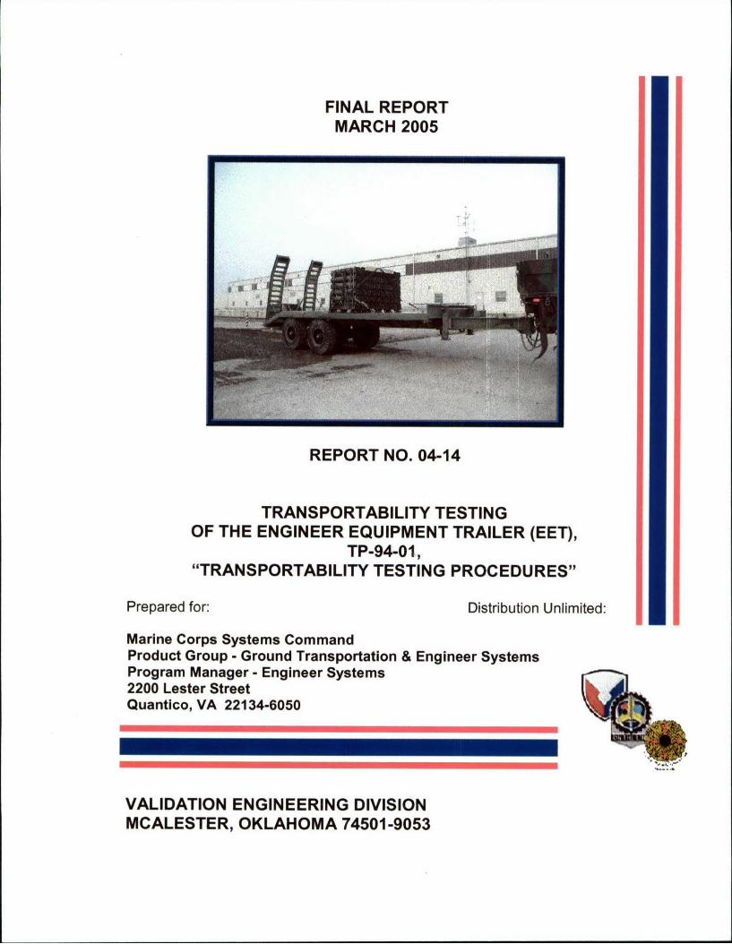
FINAL REPORTMARCH 2005
'12
REPORT NO. 04-14
TRANSPORTABILITY TESTINGOF THE ENGINEER EQUIPMENT TRAILER (EET),
TP-94-01,"TRANSPORTABILITY TESTING PROCEDURES"
Prepared for: Distribution Unlimited:
Marine Corps Systems CommandProduct Group - Ground Transportation & Engineer SystemsProgram Manager - Engineer Systems2200 Lester StreetQuantico, VA 22134-6050
VALIDATION ENGINEERING DIVISIONMCALESTER, OKLAHOMA 74501-9053
AVAILABILTY NOTICE
A copy of this report will be furnished each attendee on automatic distribution.
Additional copies or authority for reprinting may be obtained by written request
from:
DirectorU.S. Army Defense Ammunition CenterATTN: SJMAC-DEV1 C Tree Road, Bldg. 35McAlester, OK 74501-9053
DISTRIBUTION INSTRUCTIONS
Destroy this report when no longer needed. Do not return.
Citation of trade names in this report does not constitute an official endorsement.
The information contained herein will not be used for advertising purposes.
REPORT NO. 04-14 MARCH 2005TRANSPORTABILITY TESTING OF THEENGINEER EQUIPMENT TRAILER, TP-94-01, REV. 2, JUNE 2004,"TRANSPORTABILITY TESTING PROCEDURES"
ABSTRACT
The U.S. Army Defense Ammunition Center (DAC), Validation Engineering
Division (SJMAC-DEV), was tasked by the Program Manager - Engineer
Systems, Marine Corps Systems Command to conduct transportability testing on
the Engineer Equipment Trailer (EET). The EET was manufactured by Holden
Industries, Southwest City, MO. The testing was conducted in accordance with
TP-94-01, Revision 2, June 2004, "Transportability Testing Procedures."
The objective of the testing was to evaluate the EET, when transportability
tested in accordance with TP-94-01, Revision 2, June 2004.
The tie-down rings and anchors on the EET performed adequately during
testing. The utilized test loads were effectively and efficiently secured using the
tie-down provisions, as designed. The trailer, as currently designed, is adequate
for the transport of bulk ammunition.
However, the trailer, as designed, cannot transport a full 10-ton payload of
ammunition. The ammunition loads were secured forward of the deck plates and
limited to 5,020 pounds (120MM Tank Ammunition) and 5,380 pounds (155MM
Separate Loading Projectiles), to prevent overloading of the trailer lunette.
Prepared by: Reviewed by:
PHILIP W. BARICKMAN JERRY W. BEAVERLead Validation Engineer Chief, Validation Engineering Division
DEPARTMENT OF THE ARMY
US ARMY DEFENSE AMMUNITION CENTER1 C TREE ROAD
IMPLY TO MCALESTER, OK 74501-9053ATTENTION Of
SJMAC-DEV (70-1 pp) 12 April 2005
MEMORANDUM FOR SEE DISTRIBUTION
SUBJECT: Report No. 04-14, "Transportability Testing of the Engineer Equipment Trailer
(EET), TP-94-01, "Transportability Testing Procedures"
1. Enclosed please find subject report dated March 2005.
2. The POC is the undersigned, SJMAC-DEV, DSN 956-8908.
FOR THE DIRECTOR:
Encl W. BEAVER
as Chief, Validation Engineering Division
DISTRIBUTION:
Commander,Transportation Engineering Agency (MTTE-DPE) Mr. Lloyd Cato, Military Traffic
Management Command, 720 Thimble Shoals Blvd, Suite 130, Newport News, VA 23606-2574
ARDEC Logistics Research & Engineering Directorate (AMSRD-AAR-AIL-P) Al Galonski,
Bldg 455, Picatinny Arsenal, NJ 07806-5001U.S. Army Joint Munitions Command (AMSJM-TT) Richard Nesbitt, Rock Island, IL
61299-6000ARDEC Logistics Research & Engineering Directorate (AMSRD-AAR-AIL-P-(R))
Dave Piskorik, Rock Island, IL 61299-7300U.S. Army Aviation & Missile Command (AMSAM-MMC-MM-DT), Redstone Arsenal, AL
35898-5070U.S. Army Materiel Command (AMSAM-LG), 5001 Eisenhower Avenue, Alexandria, VA
22333-0001
Program ManagerMarine Corps Systems Command, Product Group - Ground Transportation & Engineer Systems,
Program Manager - Engineer Systems, 2200 Lester Street, Quantico, VA 22134-6050
(CONT)
SJMAC-DEVSUBJECT: Report No. 04-14, "Transportability Testing of the Engineer Equipment Trailer
(EET), TP-94-0 1, "Transportability Testing Procedures"
DISTRIBUTION (CONT):Director,
•.ifiense Technical Information Center, 8725 John J. Kingman Road, Suite 0944, Fort Belvoir,
VA 22060-6218
Commandant,U.S. Army Ordnance Missile & Munitions Center & School
(ATSK-CMT-Z), James Kisner, Redstone Arsenal, AL 35897-6095
U.S. Army Transportation School (ATSP-CDT), Fort Eustis, VA 23604
2

U.S. ARMY DEFENSE AMMUNITION CENTER
VALIDATION ENGINEERING DIVISIONMCALESTER, OK 74501-9053
REPORT NO. 04-14TRANSPORTABILITY TESTING OF THEENGINEER EQUIPMENT TRAILER (EET),
TP-94-01, REVISION 2, JUNE 2004 -TRANSPORTABILITY TESTINGPROCEDURES"
TABLE OF CONTENTS
PART PAGE NO.
1. INTRO DUCTIO N ............................................................................................ 1-1A. BACKGRO UND .......................................................................................... 1-1B. AUTHO RITY ............................................................................................... 1-1C. O BJECTIVE ................................................................................................ 1-1D. CO NCLUSIO N ............................................................................................ 1-1
2. ATTENDEES ................................................................................................... 2-1
3. TEST EQ UIPM ENT ......................................................................................... 3-1
4. TEST PRO CEDURES .................................................................................... 4-1A. RAIL TEST ................................................................................................. 4-1B. O N/O FF ROAD TESTS ............................................................................. 4-3
1. HAZARD CO URSE .............................................................................. 4-32. ROAD TRIP ......................................................................................... 4-43. PANIC STO PS ..................................................................................... 4-44. W ASHBOARD CO URSE ..................................................................... 4-4
C. O CEAN-G O ING VESSEL TEST ............................................................... 4-4
5. TEST RESULTS .............................................................................................. 5-15.1 TESTING DATE -3 FEBRUARY 2005 .......................................................... 5-1
A. O N/O FF ROAD TESTS ......................................................................... 5-11. HAZARD CO URSE ............................................................................ 5-12. ROAD TRIP ........................................................................................ 5-23. PANIC STO PS ................................................................................... 5-24. HAZARD CO URSE ........................................................................... 5-25. W ASHBOARD CO URSE ................................................................... 5-3
B. CO NCLUSIO N ......................................................................................... 5-4
5.2 TESTING DATE -8 FEBRUARY 2005 .......................................................... 5-5A. O N/O FF ROAD TESTS ........................................................................... 5-5
1. HAZARD CO URSE ............................................................................ 5-52. ROAD TRIP ........................................................................................ 5-63. PANIC STO PS ................................................................................... 5-64. HAZARD CO URSE ........................................................................... 5-65. W ASHBOARD CO URSE ................................................................... 5-7
B. CO NCLUSIO N ......................................................................................... 5-7
6. DRAW ING S ..................................................................................................... 6-1
PART I - INTRODUCTION
A. BACKGROUND. The U.S. Army Defense Ammunition Center (DAC), Validation
Engineering Division (SJMAC-DEV), was tasked by the Program Manager - Engineer
Systems, Marine Corps Systems Command to conduct transportability testing on the
Engineer Equipment Trailer (EET). The EET was manufactured by Holden Industries,
Southwest City, MO. The testing was conducted in accordance with TP-94-01, Revision
2, June 2004, "Transportability Testing Procedures."
B. AUTHORITY. This test was conducted lAW mission responsibilities delegated by
the U.S. Army Joint Munitions Command (JMC), Rock Island, IL. Reference is made to
the following:
1. AR 740-1, 15 June 2001, Storage and Supply Activity Operation.
2. OSC-R, 10-23, Mission and Major Functions of U.S. Army Defense Ammunition
Center (DAC) 21 Nov 2000.
C. OBJECTIVE. The objective of the testing was to evaluate the EET, when
transportability tested in accordance with TP-94-01, Revision 2, June 2004.
D. CONCLUSION. The tie-down rings and anchors on the EET performed adequately
during testing. The utilized test loads were effectively and efficiently secured using the
tie-down provisions, as designed. The trailer, as currently designed, is adequate for the
transport of bulk ammunition.
However, the trailer, as designed, cannot transport a full 10-ton payload of
ammunition. The ammunition loads were secured forward of the deck plates and limited
to 5,020 pounds (1 20MM Tank Ammunition) and 5,380 pounds (155MM Separate
Loading Projectiles), to prevent overloading of the trailer lunette.
1-1
PART 2 - ATTENDEES
ATTENDEE MAILING ADDRESS
Philip Barickman DirectorDSN 956-8992 U.S. Army Defense Ammunition Center(918) 420-8992 ATTN: SJMAC-DEV
1 C Tree Road, Bldg. 35McAlester, OK 74501-9053
Patrick Dougherty DirectorDSN 956-8225 U.S. Army Defense Ammunition Center(918) 420-8225 ATTN: SJMAC-DET
1 C Tree Road, Bldg. 35
McAlester, OK 74501-9053
2-1
PART 3 - TEST EQUIPMENT
1. Trailer, EET
Manufactured by: Holden Industries, Southwest City, MO
Manufacture Date: 12/2003
MFG. Serial Number: 12HTS31254S109391
Curb Weight: 10,440 pounds
Payload Max: 20,000 pounds
2. Truck, Cargo, 7-ton w/o Winch
Manufactured by: Oshkosh Truck Corporation, Oshkosh, WI
Date of Manufacture: 1/2004
NSN: 2320-01-465-2174
Serial No: 071519
Vehicle ID: 1OTDMWE 302S071519
Max Cargo: 30,000 pounds
Max Trailer: 22,000
3-1
PART 4 - TEST PROCEDURES
The test procedures outlined in this section were extracted from TP-94-01,
"Transportability Testing Procedures," Revision 2, June 2004, for validating
tactical vehicles and outloading procedures used for shipping munitions by
tactical truck, railcar, and ocean-going vessel.
Inert (non-explosive) items were used to build the load. The test loads
were prepared using the blocking and bracing procedures proposed for use with
munitions (see Part 6 for procedures). The weight and physical characteristics
(weights, physical dimensions, center of gravity, etc.) of the test loads were
similar to live (explosive) ammunition. The following tests identified are normally
required for transportability certification. However, not all tests will be required
for some specific items.
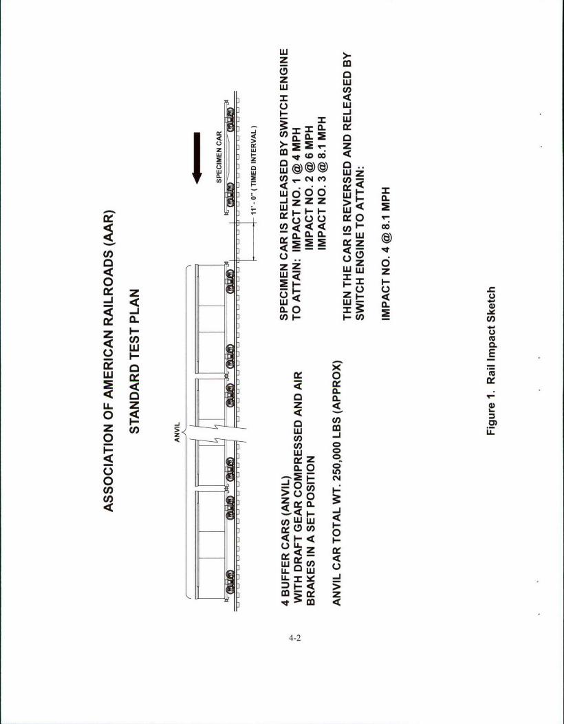
A. RAIL TEST. RAIL IMPACT TEST METHOD. The test load or vehicle will be
secured to a flatcar. The equipment needed to perform the test will include the
specimen (hammer) car, four empty railroad cars connected together to serve as
the anvil, and a railroad locomotive. The anvil cars will be positioned on a level
section of track with air and hand brakes set and with draft gears compressed.
The locomotive unit will push the specimen car toward the anvil at a
predetermined speed, then disconnect from the specimen car approximately 50
yards away from the anvil cars allowing the specimen car to roll freely along the
track until it strikes the anvil. This will constitute an impact. Impacting will be
accomplished at speeds of 4, 6, and 8.1 mph in one direction and at a speed of
8.1 mph in the reverse direction. The tolerance for the speeds is plus 0.5 mph,
minus 0.5 mph for the 4 mph and 6 mph impacts, and plus 0.5 mph, minus 0 mph
for the 8.1 mph impacts. The impact speeds will be determined by using an
electronic counter to measure the time for the specimen car to traverse an 11-
foot distance immediately prior to contact with the anvil cars (see Figure 1).
4-1
uJzz
CL I(0) CL . l>- a 2
zj Lu
w 00
* -Z ZZ >1 C.
444 U)~ ý-
LU 0
z ZW 'U
0 00
o J CO
W 0
C,,L
CO)
yLUi 40
CL0
C4
4-2
B. ON/OFF ROAD TEST.
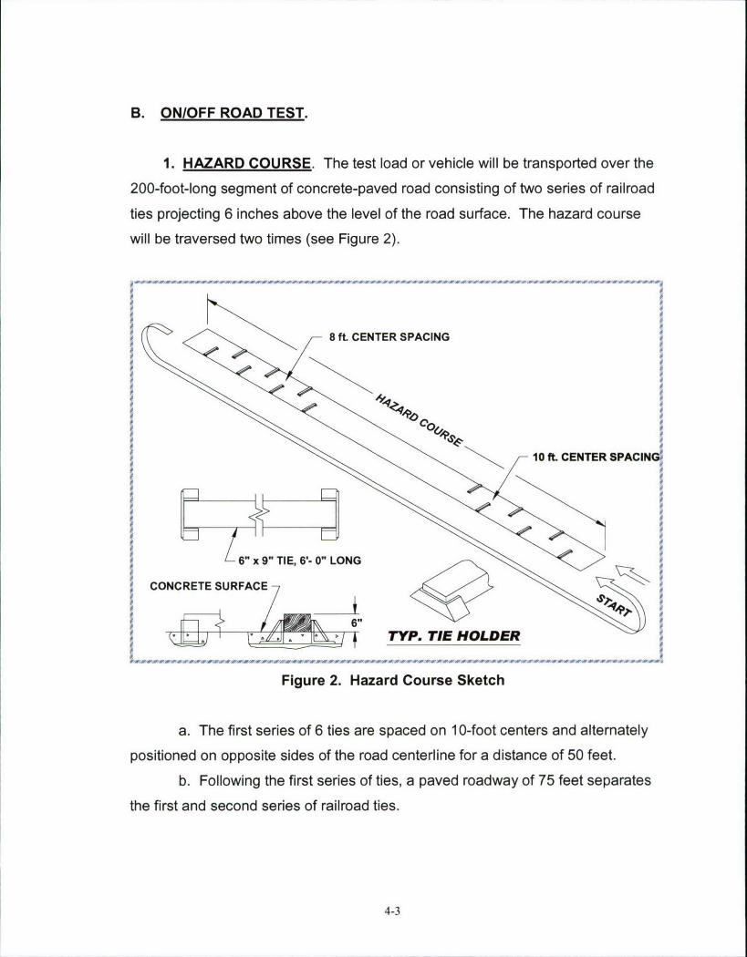
1. HAZARD COURSE. The test load or vehicle will be transported over the
200-foot-long segment of concrete-paved road consisting of two series of railroad
ties projecting 6 inches above the level of the road surface. The hazard course
will be traversed two times (see Figure 2).
9 9,
9 0
9 8 ft. CENTER SPACING9ý 9
1 99 e9 99 09 0
10& 0
L 90
10 f9CNE SAI
0199 '0
9 9=9 90
1OCRT SURA. CETR0AIG90
OA990
IAfArA900 4N
909 Y.rEHLE
-------- 9
Fiue29aad oreSec
a.Tefrtsre9f6te r pce n10fo etr n lentl
positioned 6 on opost Tide, 5o- 0" e LONGneriefraitneof5et
b.Floigtefrtsre fteapvdrawyo 5fe eaae
th CfNrEtansecodsresoUalra is
4-
c. The second series of 7 ties are spaced on 8-foot centers and
alternately positioned on opposite sides of the road centerline for a distance of 48
feet.
d. The test load is driven across the hazard course at speeds that will
produce the most violent vertical and side-to-side rolling reaction obtainable in
traversing the hazard course (approximately 5 mph).
2. ROAD TRIP. The test load or vehicle will be transported for a distance
of 30 miles over a combination of roads surfaced with gravel, concrete, and
asphalt. The test route will include curves, comers, railroad crossings and stops
and starts. The test load or vehicle will travel at the maximum speed for the
particular road being traversed, except as limited by legal restrictions.
3. PANIC STOPS. During the road trip, the test load or vehicle will be
subjected to three (3) full airbrake stops while traveling in the forward direction
and one in the reverse direction while traveling down a 7 percent grade. The first
three stops are at 5, 10, and 15 mph while the stop in the reverse direction is
approximately 5 mph. This testing will not be required if the Rail Impact Test is
performed.
4. WASHBOARD COURSE. The test load or vehicle will be driven over
the washboard course (see Figure 3) at a speed that produces the most violent
response in the vertical direction.
C. OCEAN-GOING VESSEL TEST. 80-DEGREE TILT TEST. The test load
(specimen) shall be positioned on level terrain with the bottom corner fittings
resting on timbers so the entire container is supported solely by the bottom
corner fittings. The timbers shall be oriented parallel to the end rails of the
container and extend 2 feet beyond the corner fittings on each side. Using two
mobile cranes and appropriate rigging, the container shall be rotated (tilted) using
the bottom corner fittings on one side as a fulcrum. The rigging (slings) of one
4-4

crane shall be attached to the bottom corner fittings of the long side and the
rigging (slings) of the second crane shall be attached to the top corner fittings on
the opposite side. The tilting shall be accomplished by lifting the bottom corner
fittings with the first crane so the container rotates about the opposite bottom
corner fittings (fulcrum). Lifting/rotating by the first crane is continued until the
center of gravity passes over the fulcrum, at which point the second crane shall
provide support to the container and lower the container to the 80 degrees, plus
or minus 2 degrees position. Rotation shall be accomplished smoothly at a slow
speed so the container sidewall is subjected only to the static force of the interior
load. The crane booms shall be adjusted to maintain a rear vertical suspension
of the rigging at all times. In the case of end-opening type containers, at least
one door (lower side of tilted container) must be closed and fastened throughout
the test. The container shall be held in the tilted position for a minimum of two
minutes. At which time, observations of both the container structure and the
interior load shall be made. When the test is completed, the container shall be
returned to its upright position using the same manner and care in handling.
'. .
<0
5,0
$ 55
5, '-S.• = • 2
54-
'S0'S0'S0
CONCRTE SRFAC'S0
5,b
CONCETEURFSECTO
'S 50
265 2-- - -s s s ss s s ss s s ss0s s
Figue 3.Washoar Couse Setc
4-5
PART 5 - TEST RESULTS
5.1
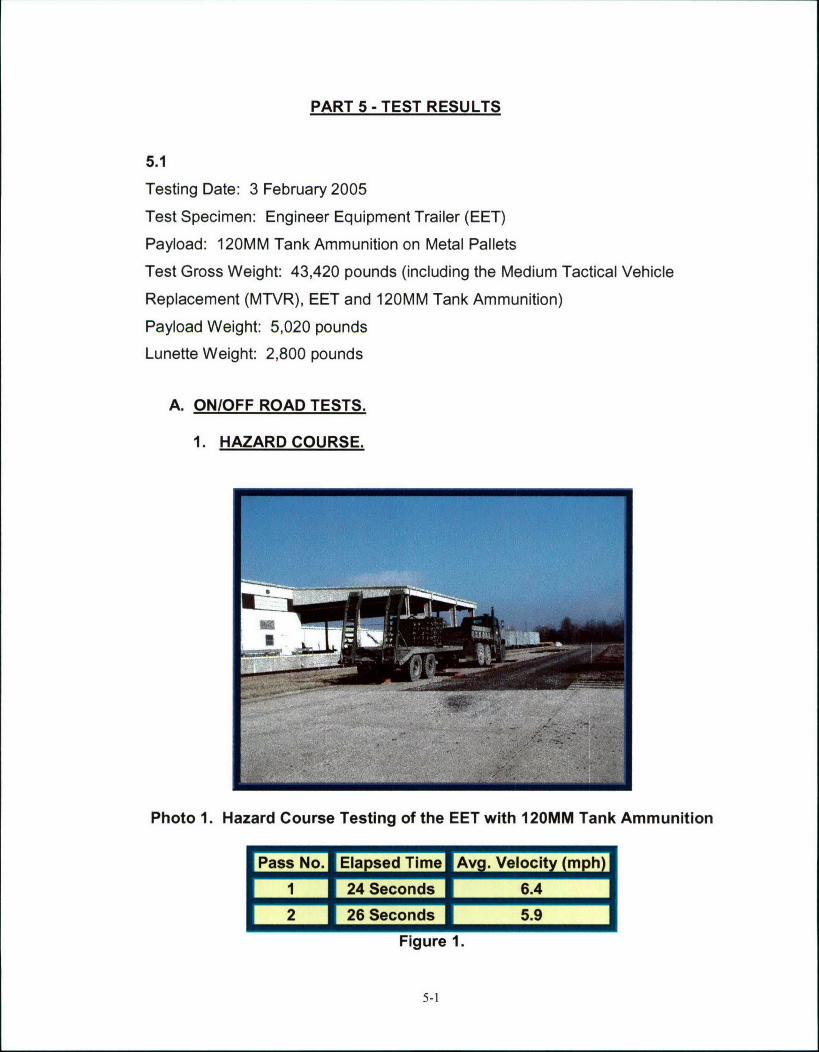
Testing Date: 3 February 2005
Test Specimen: Engineer Equipment Trailer (EET)
Payload: 120MM Tank Ammunition on Metal Pallets
Test Gross Weight: 43,420 pounds (including the Medium Tactical Vehicle
Replacement (MTVR), EET and 120MM Tank Ammunition)
Payload Weight: 5,020 pounds
Lunette Weight: 2,800 pounds
A. ON/OFF ROAD TESTS.
1. HAZARD COURSE.
Photo 1. Hazard Course Testing of the EET with 120MM Tank Ammunition
Pass No. Elapsod Time Avg. Velocity (mph)
1 24 Seconds 6.4
2 26Seconds 5.9
Figure 1.
5-1
Remarks:
1. Figure 1 lists the average speeds of the test load through the Hazard Course.
2. Inspection following Pass #1 revealed that the payload had moved 0.5-1.0
inches toward the front of the trailer and 1.0-1.5 inches toward the passenger
side.
3. Inspection following Pass #2 revealed that the payload had moved an
additional 0.25 inches toward the passenger side.
2. ROAD TRIP:
Remarks:
1. The Road Trip was conducted between the Road Hazard Course Passes #2
and #3.
2. Inspection following the completion of the Road Trip revealed that the payload
had moved an additional 0.75 inches toward the passenger side.
3. PANIC STOPS:
Remarks:
1. The Panic Stops were conducted during the Road Trip.
2. Inspection following the completion of the Panic Stops revealed no additional
movement of the payload.
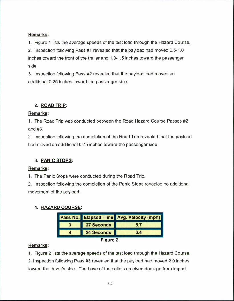
4. HAZARD COURSE:
IPass No.1 Elapsed Time fAvg. Velocity (mph)l3 27 Seconds 5.7
p 4 24 Seconds 6.4Figure 2.
Remarks:
1. Figure 2 lists the average speeds of the test load through the Hazard Course.
2. Inspection following Pass #3 revealed that the payload had moved 2.0 inches
toward the driver's side. The base of the pallets received damage from impact
5-2
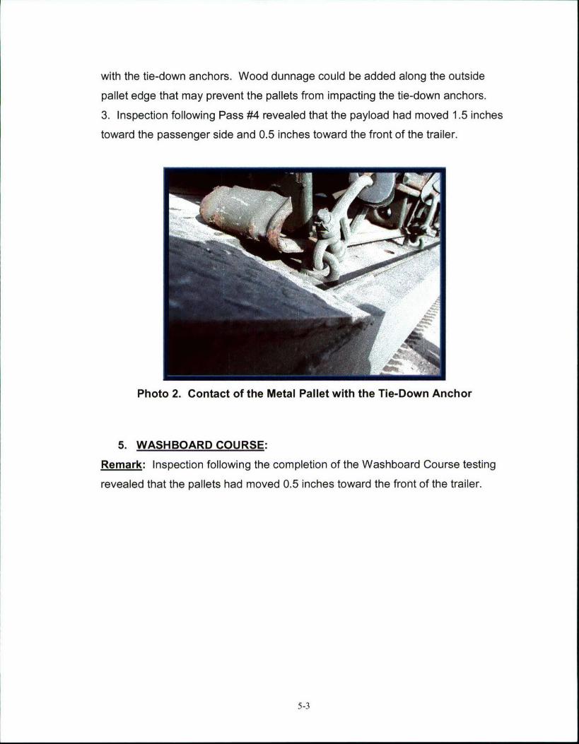
with the tie-down anchors. Wood dunnage could be added along the outside
pallet edge that may prevent the pallets from impacting the tie-down anchors.
3. Inspection following Pass #4 revealed that the payload had moved 1.5 inches
toward the passenger side and 0.5 inches toward the front of the trailer.
Photo 2. Contact of the Metal Pallet with the Tie-Down Anchor
5. WASHBOARD COURSE:
Remark: Inspection following the completion of the Washboard Course testing
revealed that the pallets had moved 0.5 inches toward the front of the trailer.
5-3
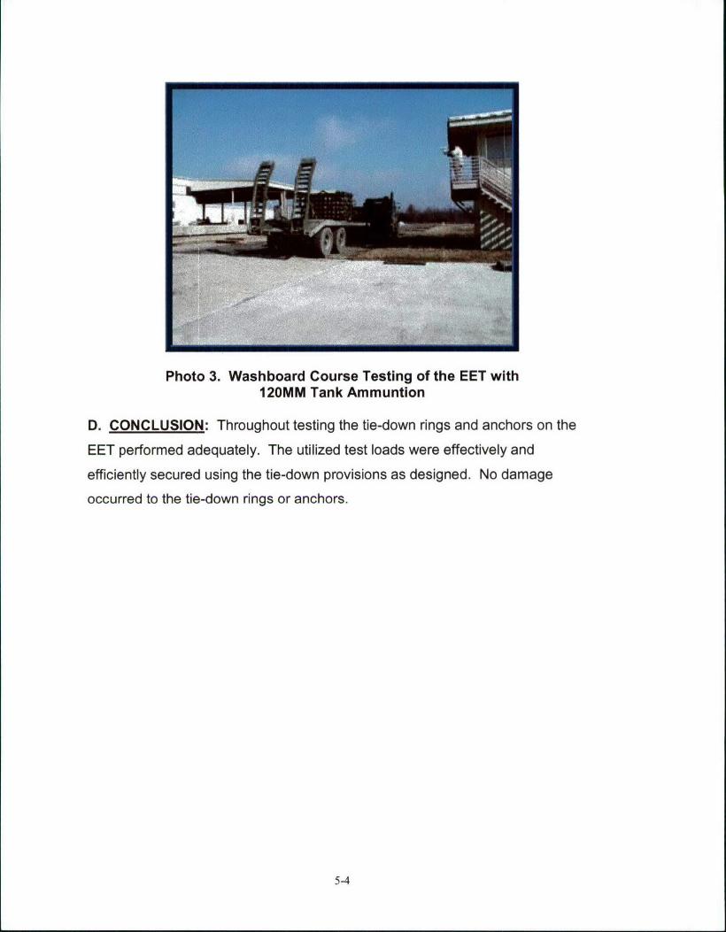
Photo 3. Washboard Course Testing of the EET with120MM Tank Ammuntion
D. CONCLUSION: Throughout testing the tie-down rings and anchors on the
EET performed adequately. The utilized test loads were effectively and
efficiently secured using the tie-down provisions as designed. No damage
occurred to the tie-down rings or anchors.
5-4
5.2
Testing Date: 8 February 2005
Test Specimen: Engineer Equipment Trailer (EET)
Payload: 155MM Separate Loading Projectiles (SLPs)
Test Gross Weight: 43,780 pounds (including the Medium Tactical Vehicle
Replacement (MTVR), EET and the 155MM SLPs)
Payload Weight: 5,380 pounds
Lunette Weight: 3,080 pounds
A. ON/OFF ROAD TESTS.
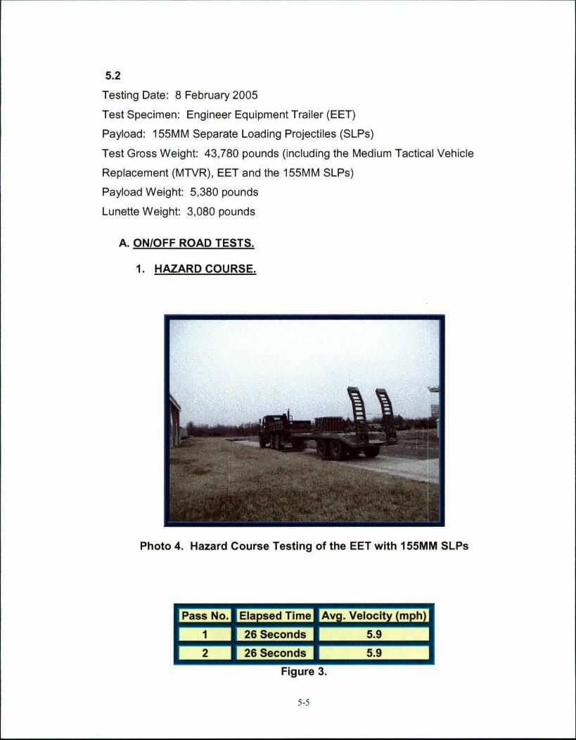
1. HAZARD COURSE.
Photo 4. Hazard Course Testing of the EET with 155MM SLPs
EPass No. Elapsed TimeAvg. Veloci (mph)
1 26 Seconds 5.926 Seconds 5.9
Figure 3.
5-5
Remarks:
1. Figure 3 lists the average speeds of the test load through the Hazard Course.
2. Inspection following the completion of Pass #1 revealed that the payload did
not move but the front cross strap loosened.
2. ROAD TRIP:
Remarks:
1. The Road Trip was conducted between the Road Hazard Course Passes #2
and #3.
2. Inspection following the completion of the road trip revealed that the payload
had moved 1-inch toward the passenger side.
3. PANIC STOPS:
Remarks:
1. The Panic Stops were conducted during the Road Trip.
2. Inspection following the completion of the Panic Stops revealed no additional
movement of the payload.
4. HAZARD COURSE:
E Pass No. IElapsed Time IAvg. Velocity (mph)
3 26 Seconds 5.94 25 Seconds 6.1
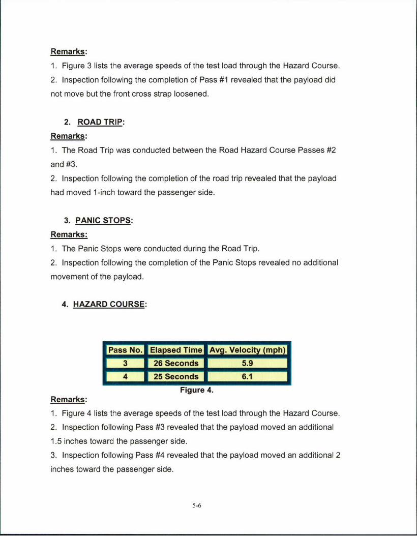
Figure 4.Remarks:
1. Figure 4 lists the average speeds of the test load through the Hazard Course.
2. Inspection following Pass #3 revealed that the payload moved an additional
1.5 inches toward the passenger side.
3. Inspection following Pass #4 revealed that the payload moved an additional 2
inches toward the passenger side.
5-6
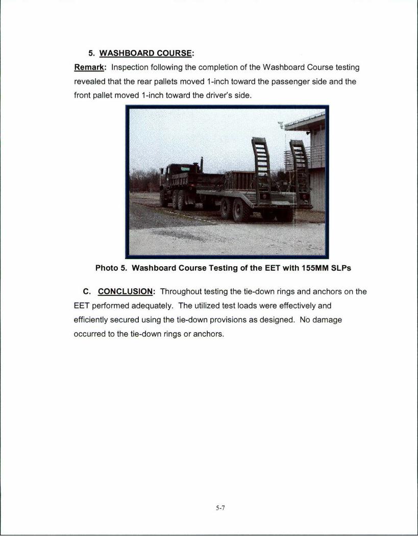
5. WASHBOARD COURSE:
Remark: Inspection following the completion of the Washboard Course testing
revealed that the rear pallets moved 1-inch toward the passenger side and the
front pallet moved 1-inch toward the driver's side.
I
Photo 5. Washboard Course Testing of the EET with 155MM SLPs
C. CONCLUSION: Throughout testing the tie-down rings and anchors on the
EET performed adequately. The utilized test loads were effectively and
efficiently secured using the tie-down provisions as designed. No damage
occurred to the tie-down rings or anchors.
5-7

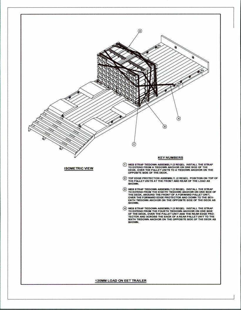
PART 6 - DRAWINGS
The following drawing represents the load configuration that was subjected to
the test criteria.
6-1
2
KEY NUMBERS
®WEB STRAP TIEDOWN ASSEMBLY (2 REQD). INSTALL THE STRAPISOMETRIC VIEW TO EXTEND FROM A 7nEDOWN ANCHOR ON ONE WOE OF THE
DECK. OVER THE PALLET UNITS TO A TIEDOWN ANCHOR ON THEOPPOSITE 810E OF THE DECK.
T TOP EDGE PROTECTION ASSEMBLY, (2 REVID). POSITION ON TOP OFTHE PALLET UNITS AT THE FRONT AND REAR OF THE LOAD ASSHOWN.
WEB STRAP TIEDOWN ASSEMBLY (2 RECID). INSTALL THE STRAPTO EXTEND FROM THE EIGHTH TiEDOWN ANCHOR ON ONE SIDE OFTHE DECK, AROUND THE FRONT OF A FORWARD PALLET UNIT,OVER THE FORWARD EDGE PROECTOR AND DOWN TO THE SEV-ENTH IEDOVVN ANCHOR ON THE OPPOSITE SIDE OF THE DECK ASSHOWN.
WEB STRAP T1EDOWN ASSEMBLY (2 RE0I). INSTALL THE STRAPTO EXTEND FROM THE FOURTH TIEDOWN ANCHOR ON ONE SIDEOF THE DECK, OVER THE PALLET UNIT AND THE REAR EDGE PRO-"TECTOR AND ACROSS THE BACK OF AREAR PALLET UNIT TO THESIXTH TIEDOWN ANCHOR ON THE OPPOSITE SIDE OF THE DECK ASSHOWN.
120MM LOAD ON EET TRAILER
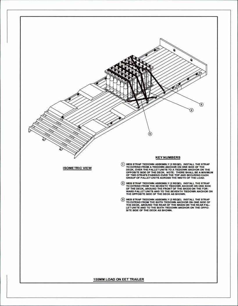
KEY NUMBERS
(•VW.B STRAP TIEDOWN ASSEMBLY (2 REDI). INSTALL THE 8TRAP
ISOMETRIC VIEW TO EXTEND FROM A TIEDOWN ANCHOR ON ONE SIDE OF THEDECK. OVER THE PALLET UNITS TO A TIEDOWN ANCHOR ON THEOPPOSITE SIDE OF THE DECK. NOTE: THERE SHALL BE A MINIMUMOF TWO STRAPS PASSING OVER THE TOP AND SECURING EACHGROUP OF PALLETUNITS ACROSS THE WIDTH OF THE LOAD.
®VWES STRAP TnEDOWN ASSEMBLY (2 REQ). INSTALL THE STRAPTO EXTEND FROM THE SEVENTH TIEDOWN ANCHOR ON ONE SIDEOF THE DECK, AROUND THE FRONT OF THE SKIDS ON THE FOR-WARD PALLET UNITS AND TO THE SEVENTH TIEDOWN ANCHOR ONTHE OPPOSITE SIDE OF THE DECK AS SHOWN.
WEB STRAP TIEDOWN ASSEMBLY (2 RECD). INSTALL THE STRAPTO EXTEND FROM THE SIXTH TIEDOWN ANCHOR ON ONE SIDE OFTHE DECK. AROUND THE REAR OF THE SKIDS ON THE REAR PAL-LET UNITS AND TO THE SIXTH TIEDOWN ANCHOR ON THE OPPO-SITE SIDE OF THE DECK AS SHOWN.
155MM LOAD ON EET TRAILER