Embed Size (px)
Citation preview
1958/59, No. 1 ·9
11. THE HYPERBOLIC-PARABOLOIDAL SHELLAND ITS MECHANICAL PROPERTIES
by C. G. J. VREEDENBURGH _*).
It was about the year 1935 that Laffaille andAimond published the first studies on the distri-bution of forces in "hypar" shells, i.e. thin-walledstructures having the form of hyperbolic para-boloids 1)2).
Shells of spherical and cylindrical form have beenused for many years but practical interest in thehypar shell dates only from the last ten years. Itwould seem that saddle surfaces (surfaces havingopposite curvatures along different directions) suchas these did not find much acceptance because theyseemed to defy architectural conventions. Moreoverit was thought that hypar shells would he morecostly to build than shells of the normal sphericaland cylindrical shapes.Views on this subject have now changed consider-
ably. Partly through the pioneering work of Candelain the U.S.A. 3) and of Hruhan in Czechoslovakia 4),it became realized that hypar shells not only possessgreat strength and stability but also lend themselvesreadily to a synthesis of striking architectural formsin keeping with various tendencies in modern art.The design of Le Corbusier and Xenakis fo~ thePhilips pavilion in Brussels which, as described inthe first article of this series, is entirely based onhyperbolic paraboloids, has certainly shown thathypar shells can be used for creating the mostspectacular architectural fantasies. Furthermore,as regards their actual construction, it is nowrecognized that hyperbolic paraboloids, because of.the two systems of straight lines inherent in them 5),are particularly well adapted to construction inwood as well as in reinforced or prestressed con-crete.
*) Professor of applied mechanics, Technische Hogeschool,Delft.
1) B. Laffaille, Mémoire sur l'étude générale des surfacesgauches minces, Mém. Assoc. Int. Ponts et Charpentes 3,295-332, 1935. . .
2) F. Aimond, Etude statique des voiles minces en paraboloïdehyperbolique, Mém. Assoc, Int. Ponts et Charpentes 4,1-112, 1936.
3) F. Candela, Structural applications of hyperbolic parabo-loidal shells, J. Amer. Concrete Inst., Title No. 51-20,January 1955, pp. 397-415.
4) K. Hruban, Obecné resem zlabovych skofepin (The generaltheory of saddle-surface shells), Institute of -TechnologyBrno, 1953.
5) See the third and fourth article of this series. A recent exam-ple of a large hypar shell consisting of glued wooden sec-tions is the roof construction of the Information Centrein the Place de Brouckère, Brussels.
624.023.744: 06I.41( 493.2) : 725.91
The hypar shell, then, has made its entry intoarchitecture a'nd is being used in many countriesand for various kinds of building. However, owingto the relative novelty of this structural form andthe greater geometrical intricacy of saddle surfaces,the contractor presented with such an assignmentwill often he unwilling to rely entirelyon experiencealready available and on his own intuition, but willenlist the aid of a scientific analysis of the expectedmechanical behaviour of the structure. It thus cameabout that, towards the end of January 1957, wewere approached by the contracting firm "Strabed"for advice concerning the building of the Philipspavilion. .
Now it is simply not possible to calculate exactlythe states of stress that can arise in such an exceed-ingly complicated structure of 'l!ihells and ribs
.. ',.' nJ-
(the latter at the intersections of the shells). On thebasis of theoretical consider~tiom;~'alone we weretherefore only able to provide Messrs. Strabedwith positive advice of a general nature regardingthe feasibility of the architects' d~sign and of theproposed method of building; in 'order to give adefinite answer to certain s'Peci~b questions re-course was necessary, partly because of the limitedtime available, to experimental stress analysis,using a model. These tests, which were performed atRijswijk and Delft (Netherlands) by A.L. Boumaand F. K. Ligtenberg, are described in the thirdarticle of this series. Nevertheless it will perhaps beuseful to show the interested reader how. far it ispossible to gowith a calculation of the general statesof stress in hyperbolic-paraholoidal shells, and to .describe the nature of the difficulties which, inintricate cases, oblige one to resort to supplementarytests on a model.
The geometry of the hypar shell
To understand the distribution of forces in ahypar shell it is first necessary to recall some factsabout its geometry:With respect to a rectangular system ofaxes
Oxyz (see fig. 1), the equation for a hyperbolicparaboloid may he written in the form:
x2 y2z=---, ....
2r1 2r2(1)
/
10 PHILIPS TECHNICAL REVIEW . VOLUME 20
Q
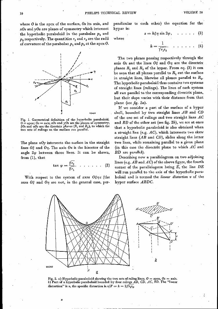
Fig. 2. a) Hyperbolic paraboloid showing the two sets of ruling lines. 0 = apex, Oz = axis.b) Part of a hyperbolic paraboloid bounded by four rulings AB, CD, AC, BD. The "lineardistortion" is v, the specific distortion is.v/F = k = l/J;;Y;.
where 0 is the apex of the surface, Oz its axis, andxOz and yOz are planes of symmetry which interseetthe hyperbolic paraboloid in the parabolae P: andP2 respectively. The quantities Tl and T2 are the radiiof curvature of the parabolae P: and P2 at the apex O.
~~~~-:--_xPl ~,_c;;:::;_.-/
P,
y
z Q5465
Fig. 1. Geometrical definition of the hyperbolic paraboloid.o = apex; Oz == axis; xOz and yOz are the planes of symmetry;gOz and 1)OZ are the directrix planes (Rl and R2), to which thetwo sets of rulings on the surface run parallel.
The plane xOy intersects the surface in the straightlines O~ and 01]. The axis Ox is the bisector of theangle 2cp between these lines. It can be shown,from (1), that
YT2tan cp = -r:::
Y Tl
With respect to the system ofaxes O~1]z (theaxes O~ and 01] are not, in the general case, per-
pendicular to each othér) the equation for thehypar is:
(3)where
1k--
- yTlT2•(4)
(2)
The two planes passing respectively through theaxis Oz and the lines O~ and 01] are the directrixplanes Rl and R2 of the hypar. From eq. (3) it canbe se~n that all planes parallel to Rl cut the surfacein straight lines, likewise all planes parallel to R2•
The hyperbolic paraboloid thus contains two systemsof straight lines (rulings). The lines of each systemall run parallel to the corresponding directrix plane,but their slope varies with their distance from thatplane (see fig. 2a).If we consider a part of the surface of a hypar
shell, bounded by two straight lines AB and CDof the one set of rulings and two straight lines ACand BD of the other set (see fig. 2b), we see at oncethat a hyperbolic paraboloid is also obtained whena straight line (e.g. AC), which intersects two skewstraight lines (AB and CD), slides along the lattertwo lines, while remaining parallel to a given plane(in this case the directrix plane to which AC andBD are parallel).
Describing now a parallelogram on two adjoininglines (e.g.AB and A C) of the above figure, the fourthcorner of the parallelogram being E, the line DEwill run parallel to the axis of the hyperbolic para-boloid and is termed the linear distortion v of thehypar surface ABDC.
8'
A·<</~.>D'
C'
",
1958/59, No. 1 PHILIPS PAVILION AT BRUSSELS, II '11
If we project the surface ABDC on to a planeperpendicular to the axial direction DE, and if the.area of this projection (parallelogram A'B'D'C/) isF, we call the ratio vlF the specific distortion, thisbeing identical with k of formula (4) and constantfor all parts of the hypar shell, bounded by fourruling lines. In practice the quantity k is usuallydetermined by calculating the specific distortion.Finally, the hyperbolic paraboloid can also be
regarded as a translation surface. For this purposelet us revert to fig. 1. All planes parallel to the planeof symmetry xOz cut the surface, according to eq.(1), in, parabolae which are congruent with PI'while all planes parallel to the plane of symmetryyOz give intersecting curves congruent with theparabola P2' We can therefore also imagine thehyperbolic paraboloid as produced by displacingparabola P2 parallel to itself, its apex gliding alongPI' or by the parallel displacement of parabola PI'its apex gliding along P2'The plane z = +c intersects the hypar, accord-
ing to eq. (1), in a hyperbola. Projecting this ontothe plane xOy, the lines og and On are the asymp-totes of this hyperbola, and Ox and Oy its real aIl:dimaginary axes respectively. For the plane z= -c,the projected intersecting curve is again a hyper-bola, again with og and On as asymptotes, but withOx as its imaginary axis and Oy as its real axis.In the special case that cp = 4.50 (og and On then
being perpendicular to each other) the above inter-secting curves are rectangular hyperbolae and thesurface is then called a rectangular hyperbolicparaboloid.If we take an arbitrary hypar and project a num-
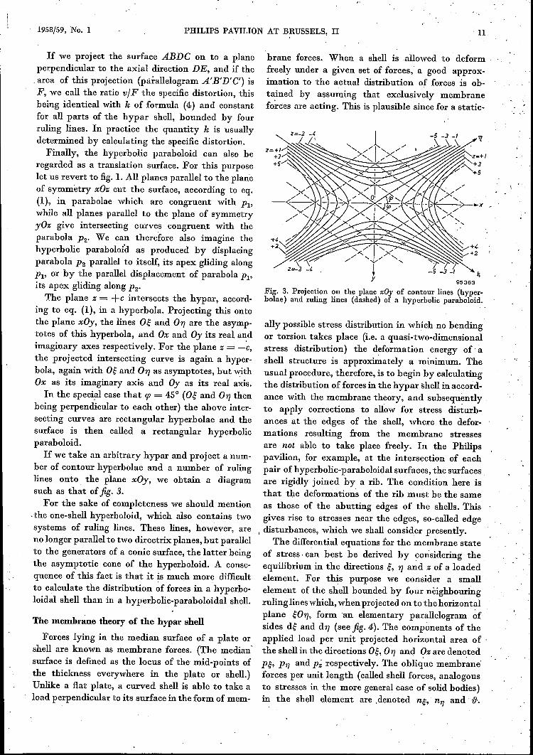
ber of contour hyperbolae and a number of rulinglines onto the plane xOy, we obtain a diagramsuch as that of fig. 3.For the sake of completeness we should mention
.the one-shell hyperboloid, which also contains twosystems of ruling lines. These lines, however, areno longer parallel to two directrix planes, but parallelto the generators of a conic surface, the latter beingthe asymptotic cone of the hyperboloid, A conse-quence of this fact is that it is much more difficultto calculate the distribution of forces in a hyperbo-loidal shell than in a hyperbolic-paraboloidal shell.
The membrane theory of the hypar shell
Forces lying in the median surface of a plate orshell are known as membrane forces. (The median'surface is defined as the locus of the mid-points ofthe thickness everywhere in the plate or shell.)Unlike a flat plate, a curved shell is able to take aload perpendicular to its surface in the form of mem-
brane forces. When a shell is allowed to deformfreely under a given set of forces, a good approx-imation to the actual distribution of forces is ob-tained by assuming that exclusively membranefo~ces are acting. This is plausible since for a static-
95363
Fig. 3. Projection on the plane xOy of contour lines (hyper-bolae) and ruling lines (dashed) of a hyperbolic paraboloid.
ally possible stress distribution in which no bendingor torsion takes place (i.e. a quasi-two-dimensionalstress distribution) the deformation energy -of' ashell structure is approximately a minimum. Theusual procedure, therefore, is to begin by calculatingthe distribution of forces in the hypar shell in accord-ance with the membrane theory, and subsequentlyto apply corrections to all~w for stress disturb-ances at the edges of the shell, where the defor-mations resulting from the membrane stressesare not able to take place freely. In the Philipspavilion, for example, at the intersection of eachpair of hyperbolic-paraboloidal surfaces, the surfacesare rigidly joined by a rib. The condition here isthat the deformations of the rib must he the sameas those of the abutting edges of the shells. Thisgives rise to stresses near the edges, so-called edge
I disturbances, which we shall consider presently.The differential equations for the membrane state
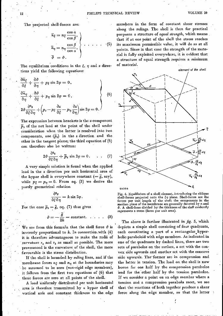
of stress, can best be derived by considering theequilibrium in the directions g, nand z of a loadedelement. For this purpose we consider a smallelement of the shell bounded by four nêighbouringruling lines which, when projected on to the horizontalplane gOn, form 'an elementary parallelogram ~fsides dg and dn (see fig. 4). The components of theapplied load per unit projected horizontal area of 'the shellin the directions og, Ol] and qz are denotedP~, PTJ and P~ respectively. The oblique membrane'forces per unit length (called shell forces, analogousto stresses in the more general case of solid bodies)ID the shell element are .denoted n~, nTJ and {J.
, -.
12 PHILIPS' TECHNICAL REVIEW VOLUME 20
The projected shell-forces are:
cos ang- ng--,
cos {3
cos {3n1] = n1)--'
cos a
"{} =-&.
(5)
.The equilibrium conditions in the g, 'Yjand z direc-tions yield the following equations:
àng eeàg + à'Yj+ pg sin 2cp= 0,
àn1) àt} . . (6);;- + ;\ + P1] Sill 2cp = 0,U17 ug
à2z ( àz àz)'2t}àgà'Yj + pz-pg àg-P1)à'Yj sin2cp=0.
The expression between brackets is the z-componentPz of the net load at the point of the shell underconsideration when the latter is resolved into twocomponents, one CPz) in the z direction and theother in the tangent plane; the third equation of (6)can therefore also be written:
à2z2t} àgà'Yj + Pz sin 2cp= O.
A very simple solution is found when the appliedload in the z direction per unit horizontal area ofthe hypar shell is everywhere constant (= g, say),while pg = P1)= O. From eq. (3) we derive thepurely geometrical relation
à2zàgà'Yj = k sin 2cp.
For the case pz . g, eg. (7) thus gives
. gt} = - - = constant. .
2k
, "
We see from this formula that the shell force t} isinversely proportional to k. In connecti~n.with (4)it is therefore advantageous to make the radii of. curvature Tl and T2 as small as possible. The morepronounced'is the curvature, of the shell, the morefavourable is the stress distribution.If the shell is bounded by ruling lines, and if the
membrane forces ng and n1) at the boundaries may.be assumed to be zero (non-rigid edge members),it follows from the first two equations of (6) thatthese forces are zero at all points of the shell.A load uniformly distributed per unit horizontal
area is therefore transmitted by a hypar shell ofvertical axis and constant thickness to the edge
members in the form of constant shear stressesalong the rulings. The shell is then for practicalpurposes a structure of equal strength, which means ,that if at one point of the shell the stress reachesits maximum permissible value, it will do so at allpoints. Since in that case the strength of the mate-rial is fully exploited everywhere, it is evident thata structure of equal strength requires a minimumof material.
element of the shell
(7)
Fig. 4. Equilibrium of a shell element, introducing the obliqueshell-forces projected onto the g1] plane. Shell-forces are theforces per uuit length of the shell; the components in themedian plane of the membrane are generally denoted by nandD. A shell-force divided by the thickness of the shell evidentlyrepresents a stress (force per uuit area).
(8)The above is further illustrated in fig. 5, which
depicts a simple shell consisting of four quadrants,each constituting a part of a rectangular. hyper-bolic paraboloid with edge members. As indicated inone of the quadrants by dashed lines, there are twosets of parabolae on the surface, a set with the con-vex side upwards and another set with the concaveside upwards. The' former are in compression andthe latter in tension. The load on the shell is nowborne for one half by the compression parabolaeand for the' other' half by the tension parabolae.If we consider a point on an edge member where atension and a compression parabola meet, we seethat the reactions of both together produce a shearforce along the edge member, so that the latter
1958/59, No. 1N, V. PHllIPS' GlOfIL~MHNfABRlfKfN
PHILlPS PAVILION AT BRUSSELS, II 13
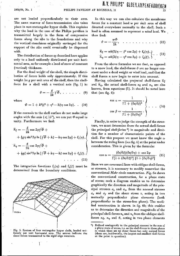
are not loaded perpendicularly to their axes.The same manner of force-transmission also takesplace in non-rectangular hypar shells. This explainswhy the load in the case of the Philips pavilion istransmitted largely in the form of compressiveforces along the ribs to the foundations and whythe vertical stanchions originally envisaged for thesupport of the ribs could eventually be dispensedwith.
The distribution of forces a,sdescribed here appliesonly to a load uniformly distributed per unit hori-zontal area, as for example a load of snow of constant(vertical) thickness.For the dead weight of the shell, the simple distri-
bution of forces holds only approximately. If thisweight be g per unit area of the shell, then the shell-force for a shell with a vertical axis (fig. 1) is:
g - .-&=--yCP, .
2k
where
If the norm als to the shell surface do not make largeangles with the axis (~ 15°), we can put cp equal tounity. Furthermore we find:
U~ = _!i._ cos 2g;y cP +2k
+ 191]sin22g; In [-y cP + k~ - k1] cos 2g;] + f1(1]),
u1] = - !i._ cos 2g;-y cP +2k '
+ tg~sin22g; In [11 cP + k1] - k~ cos 2g;] + f2(~) .
. . . . . (11)
The integration functions f1(1]) and f2(~) must bedetermined from the boundary conditions.
Fig. 5. System of four rectangular hypar shells, loaded uni-formly per unit horizontal area. The arrows indicate theshear forces transmitted to the rigid edge members.
In this way we can also calculate the membraneforces for a constant load w per Unit area of shelldirected everywhere' normally to the shell. Such aload is often assumed to represent a wind load. We.then find:
-& = _ w(/j.
2k '(12)
~~= wk(2~1] --: ~2cos 2g;) + f3( 1]), ~ . (13)u1] = wk(2~1] - 1]2cos 2g;) + f4(~)' )
(9)
From the above formulae we see that, as opposedto a snow load, the shell-forces -& are no longer con-stant under a dead weight or wind load, and that theshell forces n now begin to enter into account:Having calculated the projected shell-forces u~
and u1J' the actual shell-forces n~ and n1] are alsoknown, from equations (5). It should be noted herethat (see fig. 4): '
1cos a = ,
-VI + (àz/à~)21
cos fJ = ' . .-VI + (àzjà1])2
(14)
Finally, in orderto judge the strength of the struc-ture, we must determine from the actual shell-forcesthe principal shell-forèes G) in magnitude and direc-tion for a number of characteristic points of theshell. For this purpose we must know the angle cvbetween the ruling lines (see fig. 4.) at the point underconsideration. This is given by the formula:
cos cv= (àzjà~)(àzjà1]) + cos 2g; • (15)-Y[I + (àzjàg)2] [1 + (àzjà1])2]
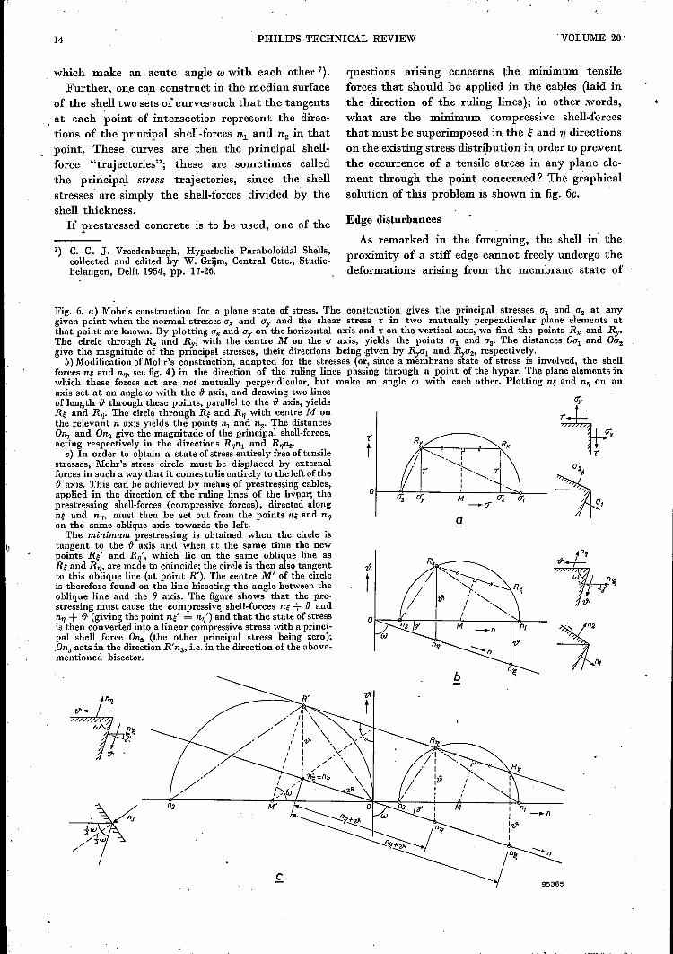
Since we are concerned here with oblique shell-forces,or stresses, it is necessary to modify somewhat theconventional Mohr circle construction. Fig. 6a showsthe conventional construction, for a plane stateof stress; such a diagram enables us to determinegraphically the direction and magnitude of the prin-cipal stresses 0'1 and 0'2' from the normal stressesO'x and O'y and the shear stress 1:, acting in twomutually perpendicular plane elements (bothperpendicular to the stress-free plane). The modi-fied construction is shown in fig. 6b; this enablesus to determine the direction and magnitude of theprincipal shell-forces n1 and n2 from the oblique shell-forces n~, n1] and -&, acting in two plane elements
G) Defined analogously to the principal stresses in the case ofa plane state of stress, i.e. as the shell-forces in those planesin which there are no shear forces but only normal forces(these are, incidentally, the largest and smallest shell-forcesat the point in question).
14 PHILIPS TECHNICAL REVIEW "VOLUME 20'
Fig. 6. a) Mohr's construction for a plane state of stress. The construction gives the principal stresses ul and u2 at anygiven point when the normal stresses Ux and uy and the shear stress 1: in two mutually perpendicular plane elements atthat point are known. By plotting Ux and uy on the horizontal axis and 1: on the vertical axis, we find the points Rx and ~.The circle through Rx and Ry, with the centre M on the u axis, yields the points ul and u2• The distances OUland OU2give the magnitude of the principal stresses, their directions being .given by Ryul and Rya2' respectively.
b) Modification ofMohr's construction, adapted for the stresses (or, since a membrane state of stress is involved, the shellforces n~ and n~,see fig. 4) in the direction of the ruling lines passing through a point of the hypar. The plane elements inwhich these forces act are not mutually perpendicular, but make an angle w with each other. Plotting n~ and ntl on anaxis set at an angle w with the IJ axis, and drawing two linesof length IJ through these points, parallel to the IJ axis, yieldsRe and Rtl. The circle through Re and Rtl with centre M onthe relevant n axis yields the points ~ and n2. The distancesOnl and On2 give the magnitude of the principal shell-forces,acting respectively in the directions R~~ and R~n2.c) In order to obtain a state of stress entirely free of tensile
stresses, Mohr's stress circle must be displaced by externalforces in such a way that it comes to lie entirely to the left of theIJ axis. This can be achieved by means of prestressing cables,applied in the direction of the ruling lines of the hypar; theprestressing shell-forces (compressive forces), directed alongne and nil' must then be set out from the points ne and ntlon the same oblique axis towards the left.The minimum prestressing is obtained when the circle is
tangent to the IJ axis and when at the same time the newpoints Re' and Rtl', which lie on the same oblique line asRe and R'I' are made to coincide; the circle is then also tangentto this oblique line (at point R'). The centre M' of the circleis therefore found on the line bisecting the angle between theoblique line and the IJ axis. The figure shows that the pre-stressing must cause the compressive, shell-forces ne + IJ and~ + IJ (giving the point ne' = n~') and that the state of stressis then converted into a linear compressive stress with a princi-pal shell force O~ (the other principal stress being zero);.Onsacts in the direction R' na, i.e. in the direction of the above-mentioned bisector.
which make an acute angle w with each other 7).Further, one can construct in the median surface
of the shell two sets of curves such that the tangents. at each point of intersection represent the direc-tions of the principal shell-forces n1 and n2 in, thatpoint. These curves are then the principal shell-force "trajectories"; these are sometimes calledthe principal stress trajectories, since the shellstresses are simply the shell-forces divided by theshell thickness.If prestressed concrete is to be used, one of the
7) C. G. J. Vreedenburgh, Hyperbolic Paraboloidal Shells,collected and edited by W. Grijm, Central Ctte., Studie-belangen, Delft 1954" pp. 17-26.
questions arismg concerns the mmnnum tensileforces that should be applied in the cables (laid inthe direction of the ruling lines); in other words,what are the minimum compressive shell-forcesthat must be superimposed in the g and 1'/ directionson the existing stress distrihution in order to pre:ventthe occurrence of a tensile stress in any plane ele-ment through the point concerned? The graphicalsolution of this problem is shown in fig. 6c.
Edge disturbances
As remarked in the foregoing, the shell ill theproximity of a stiff edge cannot freely undergo thedeformations arising from the membrane state of
T
t
a
1958/59, No. 1 PHILIPS PAVILION AT BRUSSELS, 11 15
stress. Ifwe imagine for a moment the edge memberto be separated from the shell, so that the deforma-tions can take place unhindered, it is clear that theedge of the shell and the edge member will no longerbe a precise fit. A fit is only possible when the edgemember exerts forces and moments on the edge ofthe shell (normal, shear and transverse forces, andbending and torsional moments) and the shell exertsopposite forces and moments on the edge membersuch that the extra deformations enable a perfectfit to be obtained. The calculation of these edgedisturbances, which must be superimposed onthe membrane state of stress, is one of the mostdifficult problems of shell theory.If we approximate to the hyperbolic-paraboloidal
shell in a small region by a translation surface ofcircles of radii rl and r2, then, for small curvatures,the following (tetra-harmonic) differential equationfor the edge disturbances is approximately valid:
\jBW =_ D (1-~,2)[2_ à4w _2_ à4w +2_ à4w]K r22àx4 rlr2 àx2ày2 r12 ày4 ,
where
w = displacement of a shell point in the directionof the normal, .
, à2 à2 Eb Eb3\j2 = àx2 + ày2' D = 1- '112' K - 12(1- '112) ,
b = shell thickness,E = modulus of elasticity and'11 = Poisson's ratio.
The' quantities D and K represent the tensile andbending stiffness respectively of the shell.If w is known, we can then find the entire distri-
bution or' forces. We find that the disturbancesoriginating from the edge points always consist ofthe superposition of two spatially periodic wave-forms; in many cases both waveforms are rapidly"damped", so that at some distance from the edgemembers little of the edge disturbance is perceptible.
Partly because a calculation based on equation(16) is extremely complicated, and indeed, notfeasible in the case of such intricate boundary con-ditions as exist in the Philips pavilion, the follow-ing approximate calculation of the order of magni-tude of the edge disturbances in hypar shells seemsto be entirely adequate for practical purposes. Themethod adopted is based on the fact that, so far asbending phenomena are concerned, a shell can becompared with a plate supported on an elasticfoundation. Thus if we-imagine a strip ofthe hyparshell perpendicular to an edge member, this strip willbehave to a first approximation as a beam supported
on an elastic foundation. If the local principal cur-vatures 8) of the hypar shell at the edge point inquestion be k1 and k2, then the coefficient of reac-tion (foundation modulus) for the equivalent beamon an elastic foundation is approximately:
(16)
(The coefficient of reaction of an elastic foundationis the reaction per unit area when the deflection isequal to unity. The larger c, the greater the rigidityof the foundation.]It is now possible by simple means to calculate
the variation of the edge disturbance, which is inthis case determined solely by th~ bending momentm and the transverse force q, both per unit lengthof the shell. It is found that the behaviour of theedge disturbances can he described in terms of a"wavelength" and a "damping", both of which aredetermined by a characteristic length:
À = 4 o.76i~ . (18)Vkl2 + k22
At a distance of about 3.5 À from the edge, the edgedisturbance can be assumed to be negligible. From(18) we see that the zones o( appreciable edgedisturbance are smaller the thinner the shell andthe larger the principal curvatures (i.e. the smallerthe principal radii of curvature).If the load on the shell perpendicular to its sur-
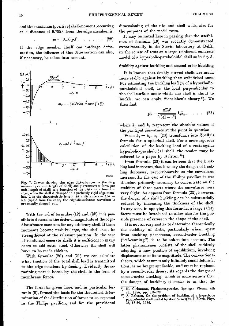
face is equal to p, and if we assume that the shellis clamped perfectly rigidly to the edge member,the edge-disturbance moment m and the edge-dis-turbance shear force q, both per unit length of shell,will vary with the distance x from the edge as illus-trated in fig. 7. From the formulae given in thefigures it can be seen that each edge-disturbancehas the form of a single damped "wave", whichcan be regarded as the resultant of the two wave-forms which satisfy equation (16). The damping isstronger the smaller the characteristic length À.
In the case considered, assuming perfect clampingat the edge, the negative clamping shell-moment is:
mo = -!pÀ2, . . . .. (19)
and the support reaction per unit length (= theshell shear force at the clamping position) is:
(20)
If the shell is hinged to the edge, the support reac-tion becomes:
(21)8) In a hyperbolic paraboloid the principal directions of cur-
vature at a given point coincide with the bisectors of theacute angle formed by the two rulings passing throughthat point, and its supplement.
16 PHILlPS TECHNICAL REVIEW VOLUME 20
and the maximum (positive) shell-moment, occurringat a distance of 0.785À. from the edge member, is:
If the edge member itself can undergo defor-mation, the influence of this deformation can also,if necessary, be taken into account.
0,3pJ...'·0,lp}..4
O"lrTTTl'TP.!~~~~~~---L.._.L.....;m",
t .0 2 3 4 5 6 7x ¥~-0,1
-0,2
-0,3
-0,4-O,S
xmx = - !p)ht2 e-X cos(1+ If)
T,OpA
0,8qx 0,6
t 0,4
x .q,,=pÀe-X cosf
95366
Fig. 7. Curves showing the edge disturbances m (bendingmoment per unit length of shell) and q (transverse foree perunit length of shell) as a function of the distance x from theedge, when the shell is clamped in a perfectly rigid edgemem-ber. l is the characteristic length. At a distance x = 3.5l =4.5 (n/4)l from the edge, the edge-disturbance waveform ispractically damped out.
With the aid offormulae (19) and (22) it is pos-sible to determine the order ofmagnitude of the edge-disturbance moments for any arbitrary shell. Ifthesemoments become unduly .Iarge, the shell must bestrengthened at the relevant position. In the caseof reinforced concrete shells it is sufficient in manycases to add extra steel. Otherwise the shell willhave to be made thicker.
With formulae (20) and (21) we can calculatewhat fraction of the total shellload is transmittedto the edge members by bending. Evidently the re-maining part is borne by the shell in the form ofmembrane forces.
The formulae given here, and in particular for-mula (8), formed the basis for the theoretical deter-mination of the distribution of forces to be expectedin the Philips pavilion, and for the provisional
(22)
dimensioning of the ribs and shell walls, also forthe purposes of the model tests.
It may be noted here in passing that the useful-ness of formula (19) was recently demonstratedexperimentally in the Stevin laboratory at Delft,in the course of tests on a large reinforced concretemodel of a hyperbolic-paraboloidal shell as in fig. 5.
Stability against buckling and second-order buckling
It is known that doubly-curved shells are muchmore stable against buckling than cylindrical ones.For estimating the buckling load Pk of a hyperbolic-paraboloidal shell, i.e. the load perpendicular tothe shell surface under which the shell is about tobuckle, we can apply Wansleben's theory 9). Wethen find:
(23)
where. kl and k2 respresent the absolute values ofthe principal curvatures at the point in question.
When kl = k2, eq. (23) transforms into Zoelly'sformula for a spherical shell. For a more rigorouscalculation of the buckling load of a rectangularhyperbolic-paraboloidal shell the reader may bereferred to a paper by Ralston 10).
From formula (23) it can be seen that the buck-ling load increases, that is to say the danger of buck-ling decreases, proportionately as the curvaturesincrease. In the case of the Philips pavilion it wastherefore primarily necessary to concentrate on thestability of those parts' where the curvatures werevery slight. As appears from formula (23), however,the danger of a shell buckling can be substantiallyreduced by increasing the thickness of the shell.In any case, in applying this formula, a large safetyfactor must be introduced to allow also for the pos-sible presence of errors in the shape of the shell.It is not an easy matter to determine theoretically
the stability of shells, particularly when, apartfrom buckling phenomena, second-order buckling("oil-canning") is to be taken into account. Thelatter phenomenon consists of the shell suddenlyadopting a new position of equilibrium, involvingdisplacements of finite magnitude. The conventiona-theory, which assumes only infinitely small deformaltions, is no longer applicable, and must be replacedby a second-order theory. As regards the danger ofsecond-order buckling, which is more serious thanthe danger of buckling, it seems to us that the
U) K. Girkmann, Flächentragwerke, Springer Vienna, 4thed., 1956, pp. 516-529.
10) A. Ralston, On the problem of buckling of a hyperbolicparaboloidal shell loaded by its own weight, J. Math. Phys.35, 53-59, 1956.
1958/59, No. 1 PHILlPS PAVILION AT BRUSSELS, II 17
hyperbolic-paraboloidal shell will be less vulnerable,owing to the saddle form, than the spherical shell.Although this has not yet been proved theoretically,our conjecture is nevertheless confirmed to some
extent by the very high stability of hypar shells,as observed in the model tests on the Philips pavi-lion which are described in the third article in thisserres.
Ill. MODEL TESTS FOR PROVING THE CONSTRUCTION OF THE PAVILION
by A. L. BOUMA *) and F. K. LIGTENBERG **).
624.023.744: 061.41(493.2) :725.91
When the contracting firm "Strabed" approachedProfessor Vreedenburgh at the end of January1957 for advice on the building of Philips pavilion,the first question was whether the design of LeCorbusier and Xenakis was indeed realizable as ashell structure of reinforced concrete. The plan ofthe contractors "Strabed" was to use concrete,5 cm thick, for making the walls, which weredesigned as hyperbolic paraboloids, these shell walls
membrane state of stress can be assumed. This willonly be the case, however, if certain boundaryconditions are satisfied. In a structure of such intri-cate shape as the pavilion under discussion, theseboundary conditions are not fulfilled in many ofthe shells, giving rise to much more complex statesof stress which are scarcely amenable to exactmathematical analysis. To answer the above ques-tion, the obvious procedure was therefore to perform
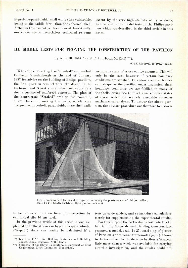
Fig. 1. Framework of tubes and wire-gauze for making the plaster model of Philips pavilion,scale 1 : 25 (T.N.O. Institute, Rijswijk, Netherlands).
to be reinforced in their lines of intersection bycylindrical ribs 40 cm thick.
In the previous article of this series it was ex-plained that the stresses in hyperbolic-paraboloidal("hypar") shells can readily be calculated if a
*) Institute T.N.O. for Building Materials and BuildingConstructions, Rijswijk, Netherlands.
**) Formerly of the Stevin Laboratory, Department of CivilEngineering, Delft Technische Hogeschool.
tests on scale models, and to introduce calculationsmerely for supplementing the experimental results.For this purpose the Netherlands Institute T.N.O.
for Building Materials and Building Constructionsprepared a model, scale 1 : 25, consisting of plasterof Paris on a wire-gauze framework (fig. I). Owingto the term fixed for the decision by Messrs Strabed,little more than a week was available for carryingout this investigation, and the results could not


![THE PARABOLOIDAL REFLECTOR ANTENNA IN RADIO …lib.iszf.irk.ru/The Paraboloidal Reflector Antenna... · chapter reference lists as [Gold, pp]. We omit a treatment of polarisation](https://img.pdfslide.us/doc/110x75/5f71221125ae015eed4f9967/the-paraboloidal-reflector-antenna-in-radio-libiszfirkruthe-paraboloidal-reflector.jpg)