Embed Size (px)
Citation preview


EPC-NPD-PG-001
Electrical Engineering
Network Servicing Policies and Guidelines
ENMAX Power Corporation (EPC)
Network Servicing Policies and Guidelines
Last Revised: July 23, 2013
Electrical Engineering ENMAX Power Corporation (EPC)
141 - 50 Ave. SE Calgary, Alberta T2G 4S7
Important - Please note the following: If there is any inconsistency between this document and any applicable EPC tariff or agreement, the terms of that tariff or agreement will prevail. The contents of this document are provided for information purposes only. The information contained within this document is not binding on EPC and can be modified by EPC without notice.

EPC-NPD-PG-001
Electrical Engineering
Network Servicing Policies and Guidelines
Intentional Blank Page

EPC-NPD-PG-001
Electrical Engineering
Network Servicing Policies and Guidelines
July 23, 2013 Page i
Table of Contents
1. GENERAL INFORMATION .............................................................................................. 1 1.1 Introduction..................................................................................................................................... 1 1.2 Voltage, Phase, Route of Service, and Utility Point of Supply....................................................... 2 1.3 The Utility Point of Connection...................................................................................................... 3 1.4 Utility Demarcation Point ............................................................................................................... 4
1.4.1 Primary services demarcation point.................................................................................. 4 1.4.2 Secondary services demarcation point ............................................................................ 5
1.5 Criteria for Changing the Type of Service, Upgrading or Making New Connections .................... 5 1.6 Number of Permitted Services ........................................................................................................ 5 1.7 Minimum Fault Level Ratings ........................................................................................................ 6
1.7.1 Street Vault Fault Levels .................................................................................................... 7 1.7.2 Customer Built Indoor Vault Fault Levels......................................................................... 7
1.8 Customer’s Equipment Causing Interference ................................................................................. 8 1.9 Metering.......................................................................................................................................... 8
2. NETWORK SYSTEMS........................................................................................................ 9 2.1 Types of Distribution Systems........................................................................................................ 9
2.1.1 Radial distribution system .................................................................................................. 9 2.1.2 Secondary Grid Network System ...................................................................................... 9 2.1.3 25kV System (Downtown area) ....................................................................................... 11
2.2 Why it Costs More to Hook-Up to a Network System.................................................................. 12
3. SUBMISSION OF PLANS................................................................................................. 13 3.1 Introduction................................................................................................................................... 13 3.2 Required Drawings ....................................................................................................................... 13 3.3 Network Customer Checklist ........................................................................................................ 14 3.4 Acceptance of Plans ...................................................................................................................... 15
3.4.1 Additional requirements ........................................................................................................ 15 3.5 Network Service Request Timelines ............................................................................................. 15
4. TECHNICAL AND SPECIAL SERVICE REQUIREMENTS ...................................... 18 4.1 Introduction................................................................................................................................... 18
4.1.1 Residential Network services........................................................................................... 18 4.1.2 Commercial Network services ......................................................................................... 18
4.2 Overhead Services ........................................................................................................................ 18 4.3 Underground Services................................................................................................................... 19
4.3.1 Conduit Installations .......................................................................................................... 20 4.3.2 Primary Service Conduit................................................................................................... 21 4.3.3 Exposed Service Conduit ................................................................................................. 22 4.3.4 Pull Box Requirements ..................................................................................................... 23
4.4 Service Entrances.......................................................................................................................... 25 4.5 Secondary Services ....................................................................................................................... 25
4.5.1 Type 1 - Secondary Services of 1600-amps or less @ 208-volts .............................. 26 4.5.2 Type 2 - Secondary Services between 1601 and 2400 amps @ 208-volts .............. 27 4.5.3 Type 3- Secondary Services of Greater than 2400-amps @ 208-volts..................... 27 4.5.4 Type 4 - Secondary Service voltages of 277/480 or 347/600-volts ........................... 28
4.6 Primary Voltage Services.............................................................................................................. 30 4.7 Network Investment Policy........................................................................................................... 30 4.8 Temporary Services ...................................................................................................................... 31 4.9 Existing Service Upgrades ............................................................................................................ 32
EPC-NPD-PG-001
Electrical Engineering
Network Servicing Policies and Guidelines
July 23, 2013 Page ii
4.10 Phased Project Investment .......................................................................................................... 32 4.11 Public Sector Utility Services ..................................................................................................... 33 4.12 Access to EPC Equipment on Private Property........................................................................... 34 4.13 EPC Phone Numbers................................................................................................................... 34
5. GENERATION ................................................................................................................... 37 5.1 Introduction................................................................................................................................... 37 5.2 Generation for Export Purposes .................................................................................................... 37 5.3 Generation for Load Shaving........................................................................................................ 38
5.3.1 Secondary Network Services........................................................................................... 38 5.3.2 Primary Services................................................................................................................ 39
5.4 Generation for Emergency Backup............................................................................................... 40 5.5 Generator Design Requirements ................................................................................................... 40 5.6 Generator Commissioning Checklist ............................................................................................ 41
6. Document History ............................................................................................................... 42
Attachments
1. ENMAX Power Corporation’s (EPC) Investment in New Services in the Network Area
2. ENMAX Power Corporation’s (EPC) Investment in Staged Projects in the Network Area
3. ENMAX Power Corporation’s (EPC) Investment in Upgraded Services in the Network Area
4. Minimum Demand Agreement
5. Living with Trees
6. Network Conduit Attachment at Property Line

EPC-NPD-PG-001
Electrical Engineering
Network Servicing Policies and Guidelines
July 23, 2013 Page 1 of 42
1. GENERAL INFORMATION
1.1 Introduction
The purpose of this guideline is to explain the basic procedural and technical requirements that must be met by the customer before ENMAX Power Corporation (EPC) can provide an electrical service connection within the Network boundaries.
The term “Network”, as it is used in this publication, refers to the area of EPC’s electrical distribution system that is located in Calgary’s downtown core and portions of the adjacent communities. For an in-depth explanation of a Network system, please see Section 2 “Network Systems”.
Please note: EPC can connect your service only after all the general and technical requirements have been met.

EPC-NPD-PG-001
Electrical Engineering
Network Servicing Policies and Guidelines
July 23, 2013 Page 2 of 42
1.2 Voltage, Phase, Route of Service, and Utility Point of Supply
To ensure a consistent high quality of service to all customers on the Network system, the EPC Electrical Engineering section reserves the right to determine the voltage, phase, and the route of the service. The service voltage level for any building in the Network area must be determined prior to the design being accepted by EPC. If the customer requires voltages or phases that are not available, the customer must supply both the necessary equipment and the space for the equipment. All such equipment must be installed on the customer’s side of the meter.
The following table lists the voltages that are typically available in the EPC Network boundaries.
Network Nominal Service Voltages
1 Phase 3 3 Phase 4 3 Phase 4 3 Phase 4 3 Phase 4 Wire Wire Wire Wire Wire
120 / 208 120 / 208 Y 277 / 480 Y 347/600 14400 / 24940 Y
The following table lists the recommended voltage variation limits for customer services. These voltages are measured at the service entrance and not at the down stream equipment locations.
Voltage Variation Limits
Nominal System Voltages
(3 Phase 4 Wire)
Extreme Operating Conditions
Normal Operating Conditions Extreme
Operation Conditions
120 / 208 108 / 187 110 / 190 125 / 216 127 / 220
277 / 480 240 / 416 250 / 432 288 / 500 293 / 508
347 / 600 300 / 520 312 / 540 360 / 625 367 / 635
Please keep in mind the following points:
Voltages that are outside the indicated limits for normal operating conditions but
within the indicated limits for extreme operating conditions will require

EPC-NPD-PG-001
Electrical Engineering
Network Servicing Policies and Guidelines
July 23, 2013 Page 3 of 42
improvement or corrective action on a planned and programmed basis, but not necessarily on an immediate basis.
Voltages that are outside the indicated limits for extreme operating conditions will
require improvement or corrective action on an emergency basis. The urgency for such action will depend on factors such as the location and nature of load or circuit involved; the extent to which limits are exceeded - with respect to voltage levels and duration; and other such factors.
Voltages that are within the indicated limits for normal operating conditions do not
require improvement or corrective action. EPC will both develop the plan and pay for the corrective action.
1.3 The Utility Point of Connection
The utility point of connection for customers, within the Network area, is defined as the point on the utility system where a customer’s electrical service will be connected to the EPC system. The utility point of connection is determined by EPC’s Electrical Engineering section.
Conduit will be installed by EPC on public property, from the utility point of
connection up to the closest property line, at the customer’s expense. In accordance with this publication, the customer is responsible for the
construction of all duct, pull pits, etc., on private property. All civil construction at the interface point between the EPC installed conduit
system and the customer’s conductor building wall must meet the requirements found in the Appendix: “Network Conduit Attachment at Property Line” specification.
The cost of the cable charges from the utility point of connection up to the
terminations on the main disconnect switch are the responsibility of the customer. The Network area supplies and installs standard service cables. The size and number of cables used are determined by the customer’s service panel size. Service cable costs are based upon the number of circuits required, the length of the customer’s service, the cable size, and the current market price of the cable that is required. The following table lists the incremental service sizes within the Network secondary system.

EPC-NPD-PG-001
Electrical Engineering
Network Servicing Policies and Guidelines
July 23, 2013 Page 4 of 42
*The sizes of cable available for services over 400 Amps are limited to cable that is rated in increasing increments of 400 amps. For example, if a customer requires a service size of 1000 amps, three 400 Amp cables (1200 amps) will be installed.
1.4 Utility Demarcation Point
The utility demarcation point for customers within the Network area, is the point where EPC’s responsibility for the utility regulations (ECUC) ends and the customer becomes responsible for meeting all of the requirements of the Canadian Electrical Code. The location of demarcation points is described below. The utility will review the prints that describe the service route to ensure they meet the applicable sections in the document with respect to the service route and access to pull pits or junction boxes. This ensures that the installation and future replacement will be as cost-efficient as possible. The customer is responsible for the supply, installation, and maintenance of conduit, fittings, pull pits, and covers located on private property.
1.4.1 Primary services demarcation point
The utility demarcation point for primary serviced customers within the Network area is the connections that are on the line side of the incoming switch. EPC and EPC Metering will lock the incoming switch and metering cells respectively.
Even though the cost of the metering cells is the responsibility of the customer, the maintenance on the metering cell must be performed by the EPC Metering section or a contractor that has been approved by EPC Metering. Having approved people maintain the metering cells ensures the integrity of the supply on the EPC system.
Please note: Customers are responsible for the scheduling of the maintenance, EPC is responsible for performing the inspection and maintenance of the metering cell.
EPC-NPD-PG-001
Electrical Engineering
Network Servicing Policies and Guidelines
July 23, 2013 Page 5 of 42
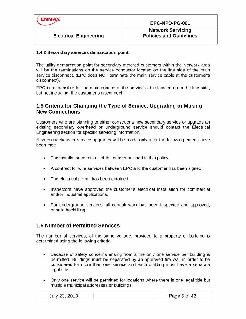
1.4.2 Secondary services demarcation point
The utility demarcation point for secondary metered customers within the Network area will be the terminations on the service conductor located on the line side of the main service disconnect. (EPC does NOT terminate the main service cable at the customer’s disconnect).
EPC is responsible for the maintenance of the service cable located up to the line side, but not including, the customer’s disconnect.
1.5 Criteria for Changing the Type of Service, Upgrading or Making New Connections
Customers who are planning to either construct a new secondary service or upgrade an existing secondary overhead or underground service should contact the Electrical Engineering section for specific servicing information.
New connections or service upgrades will be made only after the following criteria have been met:
The installation meets all of the criteria outlined in this policy. A contract for wire services between EPC and the customer has been signed. The electrical permit has been obtained. Inspectors have approved the customer’s electrical installation for commercial
and/or industrial applications. For underground services, all conduit work has been inspected and approved,
prior to backfilling.
1.6 Number of Permitted Services
The number of services, of the same voltage, provided to a property or building is determined using the following criteria:
Because of safety concerns arising from a fire only one service per building is
permitted. Buildings must be separated by an approved fire wall in order to be considered for more than one service and each building must have a separate legal title.
Only one service will be permitted for locations where there is one legal title but
multiple municipal addresses or buildings.
EPC-NPD-PG-001
Electrical Engineering
Network Servicing Policies and Guidelines
July 23, 2013 Page 6 of 42
In special circumstances, EPC may approve an application for an additional service to a building. The additional service that is requested must have a different voltage than the original service. All of the costs for the additional service, including cable, pull pits, vaults, and transformers, are the responsibility of the customer:
For locations where the customer load requires a vault to be constructed on
private property and that vault is equipped with emergency disconnect devices, then multiple services with the same voltage characteristics will be permitted. Metered services can not cross public property or any property lines. When an unmetered service cable does cross private property, EPC will require an easement to cover the EPC infrastructure from one property to another, regardless of ownership.
1.7 Minimum Fault Level Ratings
All permanent secondary Network service entrance equipment shall have the minimum fault level ratings.
Cold sequence metering is the standard for the designated Network area.
However, for residential services where the calculated fault level is less than 8800 amperes, hot sequence metering may be allowed with permission of the Electrical Engineering section and the City of Calgary Electrical Inspection Division.
Please note: Most Network fault levels for residential services will be reduced
below 8800 amperes when #2 copper service conductors are used and service length exceeds 25 meters.
For temporary 480 volt construction services, as defined in this document, the
Electrical Engineering section may approve a reduced fault level rating.

EPC-NPD-PG-001
Electrical Engineering
Network Servicing Policies and Guidelines
July 23, 2013 Page 7 of 42
1.7.1 Street Vault Fault Levels
The minimum fault ratings for Network street vaults are listed in the table below.
RMS Symmetrical Street Vault Fault Level (Amperes)
Polyphase Service Voltage 3 Phase 4 Wire Service Voltage
Voltage Amperes Voltage Amperes
120 / 208 * 120 / 208 Y 100,000**
277 / 480 Y 170,000
*This will be determined by the Electrical Engineering section.
**200,000 amperes RMS symmetrical for 3 phase, 4 wire 120/208 Y volt may be required in some locations. The customer should verify with the Electrical Engineering section prior to ordering service entrance equipment.
1.7.2 Customer Built Indoor Vault Fault Levels Bracing for a fault level of 200,000-amps is required for all main service disconnects. The following table can be used to calculate fault levels beyond the main switch.
RMS Symmetrical Customer Vault Fault Level (Amperes)
3 Phase 4 Wire Service Voltage
Voltage 500kVA 750kVA 1000kVA 1500kVA 2000kVA 2500kVA
120 / 208 110,000 165,000 215,000 - - -
277/480 - 70,000 100,000 140,000 190,000
347/600 - - - - - 190,000
EPC-NPD-PG-001
Electrical Engineering
Network Servicing Policies and Guidelines
July 23, 2013 Page 8 of 42
1.8 Customer’s Equipment Causing Interference
When a customer’s equipment causes interference with the customer’s own electrical service or the electrical service of another EPC customer, EPC may require the customer who owns the equipment causing the interference, to purchase and install specialized equipment that will correct the interference. Listed below are some examples of problems where this policy may be used:
The customer requires voltage control within unusually close tolerances. There is an imbalance of single phase and three phase loads on the customer’s
premises. The customer intermittently switches on and off large loads such as electric
boilers, heaters, welders, or electric motors.
1.9 Metering
Please refer to the “Revenue Metering Guideline” for detailed metering information. The guideline can be found at:
http://www.enmax.com/Power/Meters/default.htm
EPC will not energize a Network service that does not have a green inspection sticker. The customer must ensure they have contacted Electrical Inspection and obtained a green sticker for any of the following:
All commercial services and sub services
All temporary construction services
All residential underground services
All multi family residential services
EPC Electrical Engineering will require a copy of the single line drawing(s) approved by Electrical Inspection prior to energization to confirm the location and number of meters and main disconnect equipment EPC metering will require a copy of the shop drawings approved by Electrical Inspection (see Revenue Metering Guideline for additional information)
EPC-NPD-PG-001
Electrical Engineering
Network Servicing Policies and Guidelines
July 23, 2013 Page 9 of 42
2. NETWORK SYSTEMS
2.1 Types of Distribution Systems
EPC operates three types of distributions systems: a radial distribution system, a 25kV system (downtown) and a low voltage secondary grid Network system (downtown).
2.1.1 Radial distribution system
A radial distribution system has a single high voltage path through which power flows to the distribution transformers. In the event of an interruption on the high voltage path, power will be disrupted to all the distribution transformers and hence the customers.
To improve the reliability and reduce the interruption to the customers, a looped radial system is usually employed which permits the damaged portion of the path to be electrically removed from the system. Field staff will perform manual switching to isolate failed equipment and restore power to the customers.
Typically in a residential area, one transformer supplies up to 12 customers. In a commercial area, a 3-phase transformer would be used to supply one building.
2.1.2 Secondary Grid Network System
The secondary grid Network system is usually used in high density areas or where a diverse number and size of loads exist.
A secondary grid Network consists of multiple transformers connected to several different 13.2kV high voltage paths. The secondary (low voltage) side of the transformers are then connected together to create an electrical grid from which the individual customer services are connected. System capacity is increased in a secondary grid system by constructing new transformer vaults or by upgrading the size of the existing transformers.
A customer connected to the secondary grid Network system has improved reliability because they are connected to more then one high voltage path and there is more than one transformer supplying power to their building.

EPC-NPD-PG-001
Electrical Engineering
Network Servicing Policies and Guidelines
July 23, 2013 Page 10 of 42
An additional advantage to a secondary grid Network system is that any interruption to the high voltage feeders or transformers due to maintenance or system related issues do not result in an interruption to the customer’s power. The key component which enables the transformer low voltage side to be connected together is called a Network protector. The Network protector has two key functions:
The Network protector isolates any faults in the high voltage paths or
transformers from the other equipment. The protector opens when power flows in a reverse direction from the secondary grid into the transformer.
The second function of the Network protector is to automatically close when a
predetermined set of conditions exists within the secondary grid Network. EPC utilizes a secondary grid Network system within the downtown core area of the City of Calgary as well as at three major malls in the city (Westbrook, North Hill and Chinook Center).

EPC-NPD-PG-001
Electrical Engineering
Network Servicing Policies and Guidelines
July 23, 2013 Page 11 of 42
2.1.3 25kV System (Downtown area)
The 25kV system in the downtown area operates on a preferred / alternate scheme. When there is an outage or interruption on a preferred feeder there is an automatic break-before-make transfer in the buildings switchgear to the alternate feeder, during which a momentary interruption takes place. The return to normal operation is performed manually by EPC staff, and can be a make-before-break transfer at the buildings switchgear with NO interruption.
All customers are given an alternate path, which is fed from the opposite side of the substation bus, to reduce the impact of a substation bus or transformer failure. The alternate path is designed to have sufficient capacity to handle the loads of 3 preferred paths. The loss of 3 preferred paths could occur during a substation bus or transformer failure.

EPC-NPD-PG-001
Electrical Engineering
Network Servicing Policies and Guidelines
July 23, 2013 Page 12 of 42
2.2 Why it Costs More to Hook-Up to a Network System
Because of the large number of solidly interconnected circuits in a Network system, the fault levels are considerably higher than the fault levels in the more common radial system. To ensure public safety and to keep the secondary Network running it is necessary that every customer connected to the secondary Network system has the appropriate specialized equipment to withstand the high fault levels. If just one customer has low-quality or improperly installed equipment it will degrade the system, creating problems for everyone connected to the Network system.

EPC-NPD-PG-001
Electrical Engineering
Network Servicing Policies and Guidelines
July 23, 2013 Page 13 of 42
3. SUBMISSION OF PLANS
3.1 Introduction
Any customer who wants a new or upgraded electrical service and / or is planning to install generating equipment, must contact the Electrical Engineering section well in advance of the construction date to determine the service characteristics of the customer’s specific area.
The lead time required by EPC could be as much as 18 months because special equipment may have to be purchased, it may be necessary to perform major engineering on the Network system; or to extend the Network system infrastructure. An overview of the estimated minimum time required by EPC is found in Section 3.5 “Network Service Request Timelines”.
3.2 Required Drawings
For commercial or industrial services (including triplex or larger multi-residential structures), when requesting new or upgraded services, the customer must submit a set of plans and electrical details as listed below:
A site plan with the legal property description showing all of the buildings (existing or proposed) on the property. The site plan must include:
- all of the street designations;
- the location of service entrance, switchgear, meter centers, and other utilities (gas, telephone, sewer, etc.);
- a north or direction arrow; and
- the property boundary designations and the dimensions of building to property line.
A riser diagram showing all of the following:
- size of the main disconnect with its interrupting capacity;
- size, type and designated use of conduit along with a cross section;
- a detailed sketch of the service conductor route from termination to main disconnect including pull box location and size;
- size, type and number of service conductors;
- provisions for metering.
- the service panel maximum rating.
A load summary and panel schedule.

EPC-NPD-PG-001
Electrical Engineering
Network Servicing Policies and Guidelines
July 23, 2013 Page 14 of 42
3.3 Network Customer Checklist
Network Customer Checklist
The following information is required to initiate the EPC design process.
Contact the Project Operations section.
email: [email protected] fax: 403-385-1926 phone 403-514-1357
3
Step 1 – Budgetary/Project Feasibility Estimate Requirements
Site plan with legal property description showing all buildings, existing and proposed, on property
North direction arrow & street designations
Single line drawing
Service size (amps) and service voltage
Step 2 – Detailed Design Phase Requirements
Service conduit location, relative to adjacent lot lines, size, number of conduits, cross section, conduit use designation.
Location of service entrance, switchgear, meter centers and other utilities.
Frame size of main disconnect with interrupting capacity, size of fuses or breaker.
Size, type and number of service conductors.
Load summary and panel schedule.
For Service Energization the customer must do the following:
Approved single line which is signed or stamped
Obtain a site ID from EPC Power Service Order Control
• fax 403-514-2975 • phone 403-514-2807
Select a retailer from the government web site
• www.customerchoice.gov.ab.ca or call • 1-800-427-4088
Contact Electrical Inspection to obtain a “Green Sticker” which will indicate your

EPC-NPD-PG-001
Electrical Engineering
Network Servicing Policies and Guidelines
July 23, 2013 Page 15 of 42
service has been inspected and approved.
Contact your energy retailer to have them apply for a meter and a “Connect Order” to
have your service energized.
3.4 Acceptance of Plans
Consultants and contractors must obtain the acceptance of their plans including the location of the service conductors from the Electrical Engineering section of EPC Power Corporation.
3.4.1 Additional requirements
For 25kV high voltage services please refer to the “Network 25kV Switchgear and Switchroom Policies & Guidelines” for additional information required.
For services requiring the construction of a customer vault please refer to the “Network Customer Built Transformer Vault Guidelines” for additional information required.
3.5 Network Service Request Timelines
The services in the Network can be broken into 3 types based upon the size of service being requested by the customer. The following figures show the approximate timelines required based upon the customers service request. Note: that the timelines indicated are for working days and DO NOT include time related to activities that require customer action.

EPC-NPD-PG-001
Electrical Engineering
Network Servicing Policies and Guidelines
July 23, 2013 Page 16 of 42
Service Requests (Type 1 Projects)

EPC-NPD-PG-001
Electrical Engineering
Network Servicing Policies and Guidelines
July 23, 2013 Page 17 of 42
Service Requests (TYPE 2, 3 & 4 Projects)

EPC-NPD-PG-001
Electrical Engineering
Network Servicing Policies and Guidelines
July 23, 2013 Page 18 of 42
4. TECHNICAL AND SPECIAL SERVICE REQUIREMENTS
4.1 Introduction
This section outlines the technical and special service requirements that must be met by the customer when constructing or upgrading services that connect to EPC’s electrical Network distribution system. To maintain the high reliability of the Network system it is necessary to have standards that are higher than other typical distribution standards.
For further information, contact the Electrical Engineering section.
4.1.1 Residential Network services Residential services of 125 amps or less are permitted but only as single phase connections.
4.1.2 Commercial Network services EPC service entrance cable will be installed to match the nameplate design ampacity of the customer switch gear. EPC will not install reduced ampacity to match a de-rated or under-fused customer switch gear.
Any service of more than 30 amps must be installed as 3 phase underground. These services must be equipped with a 3 phase disconnect and be cold sequenced metered.
4.2 Overhead Services
Usually, overhead services are not permitted within the Network boundaries. Overhead services are permitted on the customer’s property when the power required does not exceed what is listed in the following table and when each of the additional criteria, listed in the paragraph below, are met.
Maximum Allowable Overhead Service
Service Size in Amperes Type of Service
Residential Commercial
1 phase 3 wire 120 / 208 125 30
3 phase 4 wire 120 /208 100 100*

EPC-NPD-PG-001
Electrical Engineering
Network Servicing Policies and Guidelines
July 23, 2013 Page 19 of 42
*Only by special permission from the Electrical Engineering section.
The following three criteria must be met before overhead services will be permitted:
The service is in an area where overhead secondary lines already exist and are
expected to remain for more than two years. The number of service heads connected to an overhead service drop are limited
to two. Any additional services requires the provision of a common electrical room.
The service is approved by the Electrical Engineering section.
Prior to installing the service entrance equipment for overhead services, the customer must receive from the Electrical Engineering section the following:
The location of the point where service wires will be attached. The path for the service wires. The location of the meter. The location of service poles, including any poles that may be required for
service drops longer than 40 meters (125 feet). The standard clearances from the ground and from the sides of buildings are found in the Alberta Electrical and Communication Utility Code. The standard clearances between trees and EPC overhead power lines are shown in Appendix:” Living With Trees”. The customer is responsible for keeping trees clear of the electrical utility wires on the customer’s property. For secondary service, a clearance of one meter (three feet) from trees must be maintained.
4.3 Underground Services
All new services in the Network area are to be underground unless the requirements for overhead connections are met and are approved by the Electrical Engineering section. The permitted service sizes are as follows:

EPC-NPD-PG-001
Electrical Engineering
Network Servicing Policies and Guidelines
July 23, 2013 Page 20 of 42
Allowable Underground Service
Minimum Service Size
(amps) Maximum Service Size
(amps)
1 phase 3 wire 120 / 208 volt N/A 125 - Residential 100* Commercial
3 phase 4 wire 120/208 volt 100 – Residential 100 - Commercial
See below
Minimum Service Size
(amps) Maximum Service Size
(amps)
3 phase 4 wire 120 /208 volt 8800
3 phase 4 wire 277/480 volt 1600 7600
3 phase 4 wire 347/600 volt 4800 8000
Notes: * Applies only to temporary services as defined in this document.
The standard clearances between trees and EPC infrastructure are shown in Appendix “Living With Trees (Underground Clearances)”.
EPC provides the service conductor(s) from the utility point of connection up to the termination on the service disconnect. The customer’s service disconnect must be sized in accordance to the fault levels as outlined in “Minimum Fault Level Ratings” found in Section 1.7.
Note: No splices are permitted in the secondary service cable between the Utility Point of Connection and the customers main service disconnect.
4.3.1 Conduit Installations The service conduit, from the utility connection point to the nearest property line, will be installed by EPC.
The customer is responsible for all costs associated with the conduit work that is required on public property.
The customer is responsible for the conduit work on private property. A plan of the cable route within the customer’s building indicating the conduit pull boxes and locations must be submitted to the Electrical Engineering section for review.
The customer is responsible for sealing the conduit at the termination within the
building.

EPC-NPD-PG-001
Electrical Engineering
Network Servicing Policies and Guidelines
July 23, 2013 Page 21 of 42
The customer is responsible for ensuring all exposed concrete encased conduit must be:
Composed of colored concrete to identify high voltage cables as per Electrical Inspection, and
Identified with surface mounted Red warning signs (minimum 12”x12”) at 5
meter intervals with the wording “CAUTION ENMAX HIGH VOLTAGE CABLES”.
All of the conduit that is located between the property line and the building must be a minimum of 100mm (4”) in diameter and be encased in a 50mm (2”) envelope of concrete.
All conduit installations are limited to
a total length of no more than 70 meters from the Utility Point of Connection and,
no more than two 90 degree bends between the service cable pull points which includes any bends in the EPC portion of the installed conduit.
The minimum radius for any bend is 36 inches.
LB conduit fittings are not permitted except by special permission of the Electrical Engineering section.
Material Used to Construct Service Entrance Conduit
Length of conduit Type of material
less than 3 meters rigid steel or concrete encased
greater than 3 meters concrete encased
4.3.2 Primary Service Conduit
The primary service entrance conduit must be as short as possible. The material used to construct the conduit is determined, in part, by the length of the conduit.
Note: Within the customer’s high voltage room conduit may not be required if the racking is in accordance with EPC Electrical Engineering standard practices and approved in advance.

EPC-NPD-PG-001
Electrical Engineering
Network Servicing Policies and Guidelines
July 23, 2013 Page 22 of 42
4.3.3 Exposed Service Conduit Within the customer’s property, conduit reductions above grade are allowed, if the conduit is located after an approved junction box. The junction box can not be smaller than 150mm by 150mm by 150mm (6 inches x 6 inches x 6 inches). For above grade installations, the conduit material and sizes listed in the table below, are approved for use in the Network area.
Exposed Service Conduit Requirements For Above Grade
Service Size Minimum Type Of Conduit Required
Service Conductor Size
Minimum Conduit Id
125 Amps Or Less Rigid PVC* #2 38mm (1.5 Inches)
150 - 200 Amps EMT* 4/0 76mm (3.0 Inches)
300 Amps Or Higher Rigid Steel Conduit Or Concrete Encased PVC
500 MCM 100mm (4 Inches)
*rigid steel or concrete encasement is required in any area that is subjected to vehicular traffic
Conduits encased in concrete, within a building, are considered the same as if they were outside of the building.
IMPORTANT NOTES:
All conduits located under floor slabs also must be concrete encased.
The entire service duct on private property is the responsibility of the owner, from the property line to the point of service.
Secondary service cable may not be racked on a customer’s property unless the cable is located within an approved and locked cable pull box or an approved enclosed raceway. Information regarding cable pull boxes is found in Section 4.3, “Underground Services”
Flexible conduit is not permitted.
EPC-NPD-PG-001
Electrical Engineering
Network Servicing Policies and Guidelines
July 23, 2013 Page 23 of 42
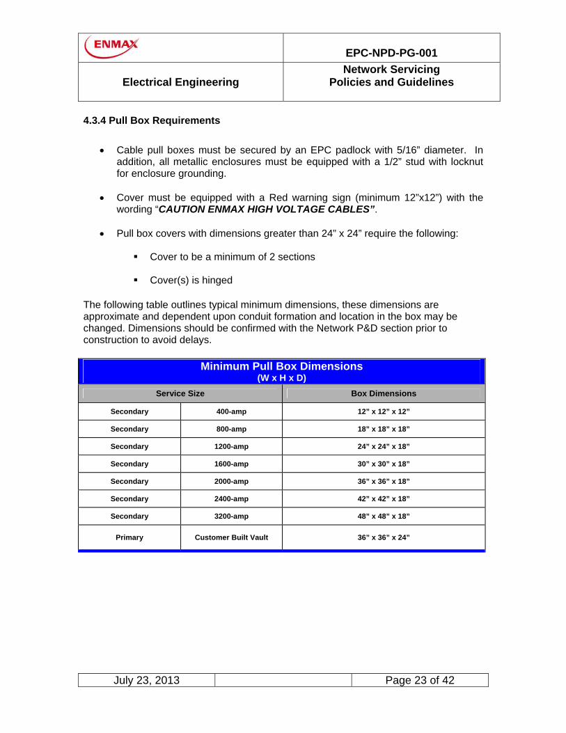
4.3.4 Pull Box Requirements
Cable pull boxes must be secured by an EPC padlock with 5/16” diameter. In addition, all metallic enclosures must be equipped with a 1/2” stud with locknut for enclosure grounding.
Cover must be equipped with a Red warning sign (minimum 12”x12”) with the
wording “CAUTION ENMAX HIGH VOLTAGE CABLES”.
Pull box covers with dimensions greater than 24” x 24” require the following:
Cover to be a minimum of 2 sections Cover(s) is hinged
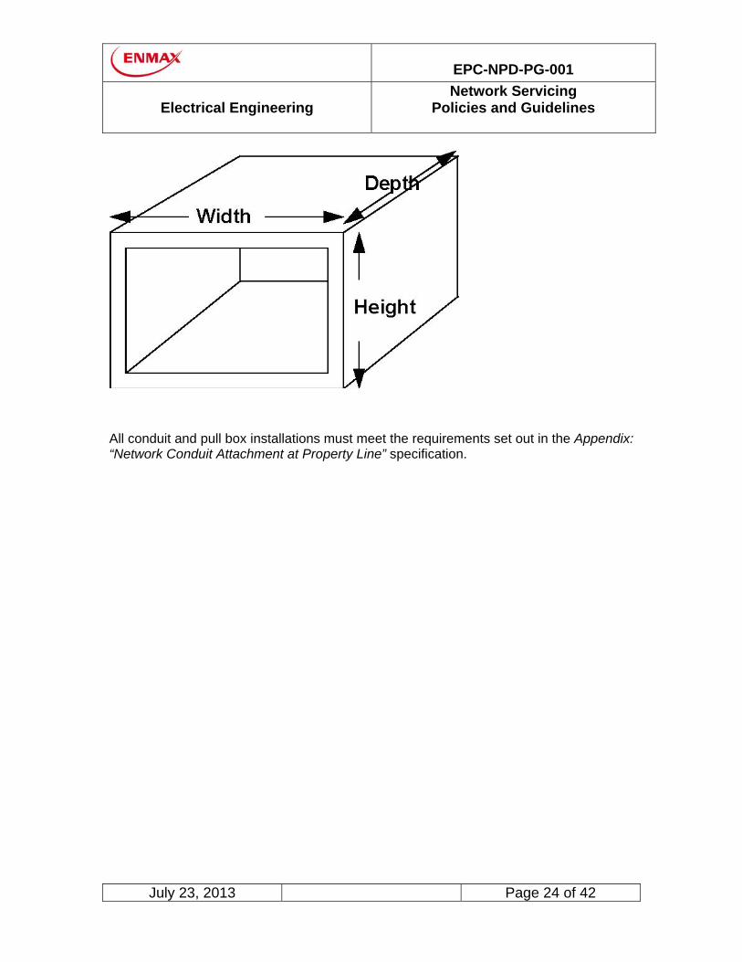
The following table outlines typical minimum dimensions, these dimensions are approximate and dependent upon conduit formation and location in the box may be changed. Dimensions should be confirmed with the Network P&D section prior to construction to avoid delays.
Minimum Pull Box Dimensions (W x H x D)
Service Size Box Dimensions
Secondary 400-amp 12” x 12” x 12”
Secondary 800-amp 18” x 18” x 18”
Secondary 1200-amp 24” x 24” x 18”
Secondary 1600-amp 30” x 30” x 18”
Secondary 2000-amp 36” x 36” x 18”
Secondary 2400-amp 42” x 42” x 18”
Secondary 3200-amp 48” x 48” x 18”
Primary Customer Built Vault 36” x 36” x 24”
EPC-NPD-PG-001
Electrical Engineering
Network Servicing Policies and Guidelines
July 23, 2013 Page 24 of 42
All conduit and pull box installations must meet the requirements set out in the Appendix: “Network Conduit Attachment at Property Line” specification.

EPC-NPD-PG-001
Electrical Engineering
Network Servicing Policies and Guidelines
July 23, 2013 Page 25 of 42
4.4 Service Entrances
The location of the main disconnect must be approved by the City of Calgary Electrical Inspection Division and must comply with any restrictions imposed by the City of Calgary’s 100 Year Flood Plain Levels Code. In addition the main disconnect(s) cannot be located above the +15 level of the building.
Bus ducts and enclosed raceways can be used only by special permission of the Electrical Engineering section. Neither bus ducts nor enclosed raceways will be considered for street vaults.
EPC Standard Service Cable Size and Rating
Service Cable Size Service Ampacity Rating
#2 125 amps
4/0 200 amps
Multiple 500 MCM Over 200 amps
Note: All service entrance conductors in the EPC Network area are to be copper.
4.5 Secondary Services
EPC Electrical Engineering installs incoming service cable ampacity which matches the customer’s main service entrance nameplate ratings.
The standard voltage offered by EPC in the Network area is 120/208 volts. Services at this voltage are classified into 3 categories:
Type 1 - Service size of 1600 amps or less @ 208-volts are typically supplied from the interconnected street grid system.
Type 2 - Service sizes between 1600 and 2400 amps @ 208-volts may require the upgrade of existing infrastructure or the construction of a new transformer vault on public or private property.
Type 3 - Service sizes of greater than 2400-amps @ 208-volts require the construction of a transformer vault on the customer’s property (see the “Customer Built Transformer Vault Guideline” for detailed information).
http://www.enmax.com/NR/rdonlyres/3D4D343D-80D8-456A-A8EC-A38657A9554F/0/Vault_Guidelines.pdf
EPC-NPD-PG-001
Electrical Engineering
Network Servicing Policies and Guidelines
July 23, 2013 Page 26 of 42
Type 4 - Secondary service voltages of 277/480 and 347/600 volts are not generally available from the street grid system and will require the construction of a transformer vault on private property (see the “Customer Built Transformer Vault Guideline” for detailed information).
http://www.enmax.com/NR/rdonlyres/3D4D343D-80D8-456A-A8EC-A38657A9554F/0/Vault_Guidelines.pdf
Note: For Type 3 & 4 services, the secondary service cable route on private property must be approved in writing by the Electrical Engineering section.
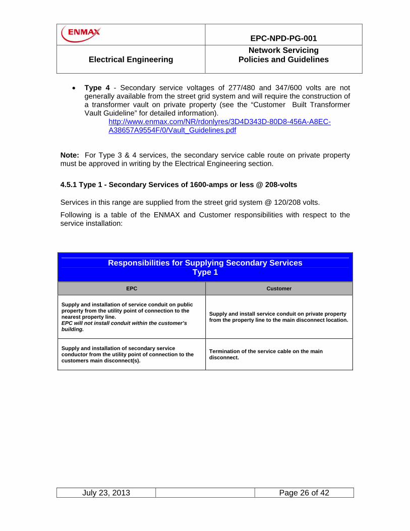
4.5.1 Type 1 - Secondary Services of 1600-amps or less @ 208-volts Services in this range are supplied from the street grid system @ 120/208 volts.
Following is a table of the ENMAX and Customer responsibilities with respect to the service installation:
Responsibilities for Supplying Secondary Services Type 1
EPC Customer
Supply and installation of service conduit on public property from the utility point of connection to the nearest property line. EPC will not install conduit within the customer’s building.
Supply and install service conduit on private property from the property line to the main disconnect location.
Supply and installation of secondary service conductor from the utility point of connection to the customers main disconnect(s).
Termination of the service cable on the main disconnect.
EPC-NPD-PG-001
Electrical Engineering
Network Servicing Policies and Guidelines
July 23, 2013 Page 27 of 42
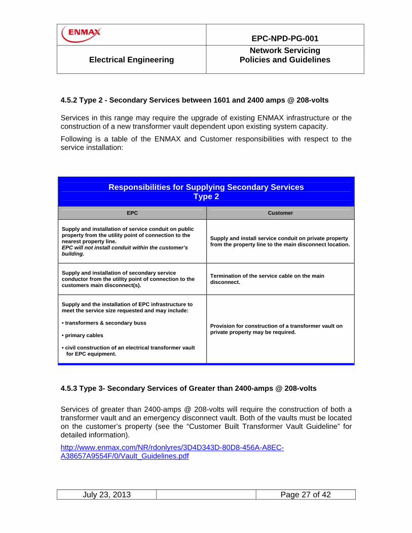
4.5.2 Type 2 - Secondary Services between 1601 and 2400 amps @ 208-volts Services in this range may require the upgrade of existing ENMAX infrastructure or the construction of a new transformer vault dependent upon existing system capacity.
Following is a table of the ENMAX and Customer responsibilities with respect to the service installation:
Responsibilities for Supplying Secondary Services Type 2
EPC Customer
Supply and installation of service conduit on public property from the utility point of connection to the nearest property line. EPC will not install conduit within the customer’s building.
Supply and install service conduit on private property from the property line to the main disconnect location.
Supply and installation of secondary service conductor from the utility point of connection to the customers main disconnect(s).
Termination of the service cable on the main disconnect.
Supply and the installation of EPC infrastructure to meet the service size requested and may include: • transformers & secondary buss • primary cables • civil construction of an electrical transformer vault for EPC equipment.
Provision for construction of a transformer vault on private property may be required.
4.5.3 Type 3- Secondary Services of Greater than 2400-amps @ 208-volts
Services of greater than 2400-amps @ 208-volts will require the construction of both a transformer vault and an emergency disconnect vault. Both of the vaults must be located on the customer’s property (see the “Customer Built Transformer Vault Guideline” for detailed information).
http://www.enmax.com/NR/rdonlyres/3D4D343D-80D8-456A-A8EC-A38657A9554F/0/Vault_Guidelines.pdf

EPC-NPD-PG-001
Electrical Engineering
Network Servicing Policies and Guidelines
July 23, 2013 Page 28 of 42
The transformer vault may supply more than one service in a customer’s building
provided that all of the main service disconnects are grouped into a common electrical room and the location is approved by the City of Calgary Electrical Inspection Division.
The transformer vault may serve more than one building provided all the
proposed service cables remain within the site where the vault is located and a general easement is provided to cover all of the EPC equipment.
Responsibilities for Supplying Secondary Services Type 3
EPC Customer
Supply and installation of system conduit on public property from the utility point of connection to either the transformer vault or the property line. EPC will not install conduit within the customer’s building.
Supply and install service conduits on private property from the EPC facility to the main disconnect location.
Supply and installation of secondary service conductor from the utility point of connection to the customers main disconnect(s)
Termination of the service cable on the main disconnect
Supply and the installation of: • transformers & secondary buss • primary cables • civil construction of an electrical transformer vault emergency disconnect vault and emergency
disconnect devices for EPC equipment.
Provision on the property for the construction of a transformer vault, lift out well and emergency disconnect vault as set out in the Network Servicing Customer Built Vault Guidelines.
4.5.4 Type 4 - Secondary Service voltages of 277/480 or 347/600-volts
Services at these voltage levels will require the construction of both a transformer vault and an emergency disconnect vault. Both of the vaults must be located on the customer’s property (see the “Customer Built Transformer Vault Guideline” for detailed information).
http://www.enmax.com/NR/rdonlyres/3D4D343D-80D8-456A-A8EC-A38657A9554F/0/Vault_Guidelines.pdf

EPC-NPD-PG-001
Electrical Engineering
Network Servicing Policies and Guidelines
July 23, 2013 Page 29 of 42
The transformer vault may supply more than one service in a customer’s building
provided that all of the main service disconnects are grouped into a common electrical room and the location is approved by the City of Calgary Electrical Inspection Division.
The transformer vault may serve more than one building provided all the
proposed service cables remain within the site where the vault is located and a general easement is provided to cover all of the EPC equipment.
Responsibilities for Supplying Secondary Services Type 4
EPC Customer
Supply and installation of system conduit on public property from the utility point of connection to either the transformer vault or the property line. EPC will not install conduit within the customer’s building.
Supply and install service conduits on private property from the EPC facility to the main disconnect location.
Supply and installation of secondary service conductor from the utility point of connection to the customers main disconnect(s)
Termination of the service cable on the main disconnect
Supply and the installation of: • transformers & secondary buss • primary cables • civil construction of an electrical transformer vault emergency disconnect vault and emergency
disconnect devices for EPC equipment.
Provision on the property for the construction of a transformer vault, lift out well and emergency disconnect vault as set out in the Network Servicing Customer Built Vault Guidelines.
Important note: In special circumstances consideration will be given to 347/600 volts - minimum service size of 5 MVA. Restricted to indoor vaults only.

EPC-NPD-PG-001
Electrical Engineering
Network Servicing Policies and Guidelines
July 23, 2013 Page 30 of 42
4.6 Primary Voltage Services
Primary voltage services are reserved for high density customers (minimum of 5 MVA) at an EPC service voltage of 25kV.
Responsibilities for Supplying Primary Voltage Services
EPC Customer
Supply and install the service conduit on public property from the utility point of connection to property line.
Supply and install service conduit on private property.
Supply and install the primary conductor and all the utility work from the utility point of connection up to the utility demarcation point.
Construction of a room within the building which meets the criteria set out in the 25kV Switchroom/Gear Guideline and Procedure. Primary voltage switchgear which meets the criteria set out in Network Servicing 25kV Guidelines.
Supply and installation of equipment required for emergency disconnect of the customer built transformer vault.
Provision for a vault to house the emergency disconnect devices which meet the criteria set out in the Network Servicing Customer Built Vault Guidelines.
Perform all electrical work from the utility point of connection to the utility demarcation point including termination of the service cable on the main disconnect.
Note: For Primary Services, the primary cable route on private property must be approved in writing by the Electrical Engineering section.
4.7 Network Investment Policy
EPC’s financial contribution towards the construction of the electrical service is outlined in Appendices 1 to 3.
If there are any questions as to who is responsible for the costs of equipment or installation that is required to provide the service, please contact the Electrical Engineering section.

EPC-NPD-PG-001
Electrical Engineering
Network Servicing Policies and Guidelines
July 23, 2013 Page 31 of 42
4.8 Temporary Services
Temporary services may include construction services, pay phones, signs, surface parking lots and other limited term development permits (5 years or less). Services must be installed in accordance with conditions as outlined in the Development Permit (if applicable) and under the condition that they will be removed 30-days after formal notification from the Electrical Engineering section.
These services may be allowed as an additional service with the approval of the Electrical Engineering section.
Where EPC reasonably believes that a requested service will be temporary, EPC will require the customer requesting the service to pay EPC’s total estimated cost of installation. EPC will remove the temporary service at the customers request, the customer has the option to keep the salvageable material and pay for removal or have EPC remove the service and keep the salvageable material.
Construction services are permitted for a duration of one year from the connection date. The service time can be extended after review and approval by the Electrical Engineering section.
EPC will determine if system capacity is available to meet the construction service requirements. If additional capacity is required to meet the construction service request, the customer will be responsible for all additional costs.
Cold sequence metering is required in conjunction with a disconnect equipped with HRC “J” class fusing.
Overhead construction services: This type of service of 125 amperes or less may be permitted by the Electrical Engineering section provided overhead services already exist and capacity is available.
Underground construction services: Must meet the conditions listed in Section 4.3 “Underground Services”.
Other temporary services: includes signs, pay phones, surface parking lots and other limited term development permits (five years or less). Services will be installed in accordance with conditions as outlined in the Development Permit.

EPC-NPD-PG-001
Electrical Engineering
Network Servicing Policies and Guidelines
July 23, 2013 Page 32 of 42
Overhead temporary services: Will be considered if overhead services exists and expects to remain for at least two years and meet the following two criteria.
The development permits overhead connections Service is a maximum size of 125 amperes single phase
Underground temporary services: Will be permitted under the same conditions as Underground Temporary Construction Services.
4.9 Existing Service Upgrades
For existing electrical services where the customer’s building renovation or upgrade will require a new or upgraded service, the existing EPC Investment policy will be applied to the increase in demand or number of EPC meters installed. An upgrade will be considered to be a service (s) which currently exists and an increase in service capacity is requested. Please see Appendix 3.
Note: If the permanent and all of the temporary services have been removed for a period longer than six months the request will have to be considered as a new service and the request will have to adhere to all of the requirements for a new service.
4.10 Phased Project Investment
For all services, new or upgrades, where the project involves multiple phases, EPC will view the project as a single project, from an investment perspective, provided all the following conditions are met.
There is the same owner for all project phases The infrastructure does not cross public property. Easements will be required for
any infrastructure crossing property lines on the same project. Each phase of the project is treated as a separate project from a financial and
investment perspective. All construction costs will be finalized at the completion of each phase.
A letter of intent is signed either by the owner or their representative, that states
the work will commence on the subsequent phase of the project within 2-years of the energization date of the previous phase.
The investment level will be based upon the current EPC Investment Policy in place at the time construction commences. Please see Appendix 2.

EPC-NPD-PG-001
Electrical Engineering
Network Servicing Policies and Guidelines
July 23, 2013 Page 33 of 42
4.11 Public Sector Utility Services
Utility services are generally situated on public property and may be defined as:
parks and irrigation power services; traffic controller power services; street light relay power services; or communication companies power service.
For service sizes that are 100 amps three phase and greater, all of the existing conditions of Network servicing must be adhered to.
For service sizes that are less than 125 amps, single phase or less than 100 amps three phase, the following conditions apply.
Conduit size can be reduced to 2 inch rigid PVC versus 4 inch concrete encased
conduit. The conduit will be supplied, installed, owned and maintained by the customer.
Location of the connection between the service conduit and the EPC Network
structure must be approved by EPC Electrical Engineering before work can proceed.
The coring of the EPC Network structure will be performed by EPC Network
crews. Any cable installation or stand-by will be performed by EPC Network crews. All cable fusing and connection will be performed by EPC crews. The cable installed between EPC utility point of connection and the customer’s
main disconnect will be supplied, owned, and maintained by the customer. The cable conductor must be copper.
As requested by Network P&D, a signed letter from the Property Owner
indicating their approval for the scope of work on their property. The scope of work and the approval letter must be submitted to Network P&D.

EPC-NPD-PG-001
Electrical Engineering
Network Servicing Policies and Guidelines
July 23, 2013 Page 34 of 42
In addition to these requirements all of the costs from the utility point of connection (civil and electrical) are charged to the customer.
4.12 Access to EPC Equipment on Private Property
EPC must have access, 24 hours a day, to all vaults and substations. When the vaults and substations are located on the customer’s property it is important that EPC be allowed 24 HOUR unimpeded access to be able to service, repair, or replace equipment. The access must be via one of the following methods:
A private outside entrance that has been keyed by EPC; When the outside entrance has not been keyed by EPC there is a key box
available to EPC staff that contains all of the necessary keys. Access via an indoor vault and/or primary switchgear room that meets the
requirements outlined in the Network Customer Built Transformer Vault Guidelines and/or Network 25kV Switchgear and Switchroom Policies and Guidelines.
4.13 EPC Phone Numbers
Please keep in mind that the following numbers are subject to change. These numbers were accurate at the time of the publication of this guideline.
To obtain electrical service, first, call the following number and request a Site ID:
EPC Power Service Order Control
at
403-514-2807 or Fax 403-514-2975
You will then be required to select a retail service provider and to provide this retailer with your Site ID.

EPC-NPD-PG-001
Electrical Engineering
Network Servicing Policies and Guidelines
July 23, 2013 Page 35 of 42
A list or retail service providers is available from the Government of Alberta’s web site at:
www.ucahelps.gov.ab.ca/4.html
or by calling
1-403-310-4822
Important note: EPC cannot energize any service that has not been successfully enrolled by a retailer.
Because the length of time required to obtain a site ID and have the site enrolled by a retailer is usually between 2 - 5 business days, it is not possible to provide same day service to energize new sites. If energy is needed for a new service on a particular day, a site ID must be obtained and a retailer selected in advance of the date electrical service is required.
EPC-NPD-PG-001
Electrical Engineering
Network Servicing Policies and Guidelines
July 23, 2013 Page 36 of 42
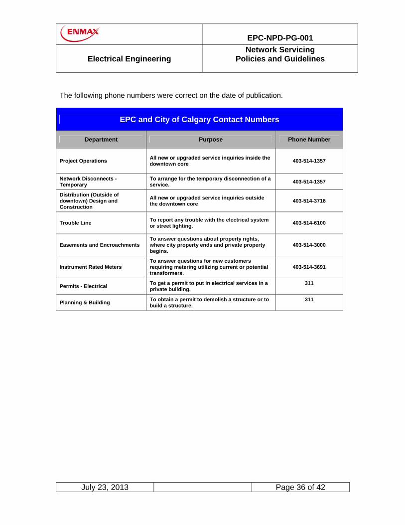
The following phone numbers were correct on the date of publication.
EPC and City of Calgary Contact Numbers
Department Purpose Phone Number
Project Operations All new or upgraded service inquiries inside the downtown core
403-514-1357
Network Disconnects - Temporary
To arrange for the temporary disconnection of a service.
403-514-1357
Distribution (Outside of downtown) Design and Construction
All new or upgraded service inquiries outside the downtown core
403-514-3716
Trouble Line To report any trouble with the electrical system or street lighting.
403-514-6100
Easements and Encroachments To answer questions about property rights, where city property ends and private property begins.
403-514-3000
Instrument Rated Meters To answer questions for new customers requiring metering utilizing current or potential transformers.
403-514-3691
Permits - Electrical To get a permit to put in electrical services in a private building.
311
Planning & Building To obtain a permit to demolish a structure or to build a structure.
311

EPC-NPD-PG-001
Electrical Engineering
Network Servicing Policies and Guidelines
July 23, 2013 Page 37 of 42
5. GENERATION
5.1 Introduction
Customers wishing to install a generator for the purposes of export, load shaving, or emergency backup must contact Electrical Engineering. Customers are also responsible to contact the Alberta Utilities Commission (http://www.auc.ab.ca) to ensure they have received all the required approvals. EPC Power has created two guides to assist customers with their generation design. These documents are “Guide for Generator Interconnection to the Wires Owner Distribution System” and “Guide for Micro-Generation Interconnection to the Wires Owner Distribution System”. These guides may be found on the EPC Power website at: http://www.enmax.com/Power/Our+Services/Technical+Specs+and+Guidelines/Generator+Guidelines.htm. Due to the differences between a secondary Network and a traditional distribution system, there are additional requirements for customers looking to install generation on a secondary Network. The requirements set out in this document are to be considered in addition to the two guides mentioned above.
5.2 Generation for Export Purposes
Generation for the purpose of export is NOT permitted on the secondary Network system. Secondary Networks are not designed to allow customers to export power. Any attempt to export power into the secondary Network would create the following problems:
Islanding of the building once generation exceeds the building load. Damage to the Network protectors and generator upon reconnection to
the secondary Network.
Safety issues for EPC personnel from unanticipated generation into the secondary Network.
Generation for the purpose of export may be considered via high-voltage (typically 25kV) non-Network feeders. All costs associated with the high voltage service and switchgear required to accommodate export of power will be at the customer’s expense. Technical Requirements for this type of generation are defined in the previously mentioned EPC interconnection guides.

EPC-NPD-PG-001
Electrical Engineering
Network Servicing Policies and Guidelines
July 23, 2013 Page 38 of 42
5.3 Generation for Load Shaving
Customers wishing to install generating equipment for the purpose of load shaving may do so provided they meet the requirements for their type of service. 5.3.1 Secondary Network Services
Customers connected to a secondary Network service must have a reverse power or reverse current relay to prevent backfeed into the system. The relay must be set above zero to ensure a net import of power. The minimum import level varies between buildings and will be determined by Electrical Engineering. The reverse power relay must sense the power flow on the main service, and trip out the generator main breaker.
Sample Single Line Diagram for a Network Service with Generator
EPC-NPD-PG-001
Electrical Engineering
Network Servicing Policies and Guidelines
July 23, 2013 Page 39 of 42
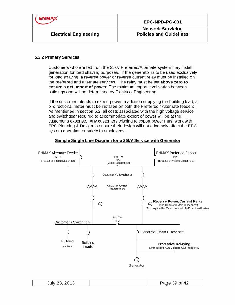
5.3.2 Primary Services
Customers who are fed from the 25kV Preferred/Alternate system may install generation for load shaving purposes. If the generator is to be used exclusively for load shaving, a reverse power or reverse current relay must be installed on the preferred and alternate services. The relay must be set above zero to ensure a net import of power. The minimum import level varies between buildings and will be determined by Electrical Engineering. If the customer intends to export power in addition supplying the building load, a bi-directional meter must be installed on both the Preferred / Alternate feeders. As mentioned in section 5.2, all costs associated with the high voltage service and switchgear required to accommodate export of power will be at the customer’s expense. Any customers wishing to export power must work with EPC Planning & Design to ensure their design will not adversely affect the EPC system operation or safety to employees.
Sample Single Line Diagram for a 25kV Service with Generator
Customer’s Switchgear
BuildingLoads
BuildingLoads
G
Generator
Protective RelayingOver current, O/U Voltage, O/U Frequency
Generator Main Disconnect
32Reverse Power/Current Relay
(Trips Generator Main Disconnect)*Not required for Customers with Bi-Directional Meters
32
Bus TieN/O
Bus TieN/C
(Visible Disconnect)
ENMAX Alternate FeederN/O
(Breaker or Visible Disconnect)
ENMAX Preferred FeederN/C
(Breaker or Visible Disconnect)
Customer HV Switchgear
Customer Owned Transformers

EPC-NPD-PG-001
Electrical Engineering
Network Servicing Policies and Guidelines
July 23, 2013 Page 40 of 42
5.4 Generation for Emergency Backup
Emergency backup generators may be installed provided they are never connected to the EPC system. The generators operation must be conditional on all incoming breakers or disconnects being open. When transitioning back to the utility supply, the customer switchgear must disconnect the generator before closing the incoming breaker(s) in a break-before-make fashion. If synchronization between the generator and the EPC system is required, the generator must be treated as a load shaving or export configuration.
5.5 Generator Design Requirements
When submitting an application for a generator interconnection, the customer must provide Electrical Engineering with:
A single line diagram (such as in section 5.3.1 or 5.3.2). The proposed generator size, type, voltage, connection, and physical location. The protection and control settings and equipment types. A coordination study. (Please allow a minimum of 10 working days for EPC to
review). The customer’s generation interruption device must isolate the generator from the utility in any of the following conditions:
A customer relay alarm. Relay maintenance or relay removed. Loss of power to the reverse power (or reverse current) relay, while generator is
running. Relay control voltage failure. Minimum import level not satisfied or reverse power flow detected.
The main service disconnect must be sized to match the expected full load of the service and must be equipped with:
A visible open with provision for a locking hasp to accommodate an EPC padlock.
A red laminated sign stating:
“UTILITY MAIN INTERRUPTING DEVICE”
A yellow laminated sign stating
“CAUTION – TO PREVENT BACKFEED INTO THE UTILITY SYSTEM THE MAIN INTERRUPTING DEVICE MUST BE RACKED OUT
AND LOCKED OUT”

EPC-NPD-PG-001
Electrical Engineering
Network Servicing Policies and Guidelines
July 23, 2013 Page 41 of 42
5.6 Generator Commissioning Checklist
Generators wishing to synchronize to the EPC system for any reason must have the commissioning tests witnessed by EPC. The following checklist must be signed off by EPC before commissioning is complete.
Network Generator Commissioning Checklist
Date On site testing will consist of the following:
1. System synchronization to the EPC Network system.
2. During the loss of utility supply while generating (island operation) the customer’s equipment must be able to do the following:
• Isolate and disconnect from utility system; • Prevent generation back into the utility system; • Generate provided main disconnect is locked open. Please Note: The previous three criteria also apply to the customer when the utility supply comes back on line, to prevent damage to the customer’s equipment.
3. Reverse power relay operates according to EPC requirements.
4. Protection schemes must be operating properly:
• Over and under frequency meet ESBI requirements document; • Over and under voltage; • Over current; • Phase imbalance.
5. Generator is able to pick up load.
6. Alarm system is in place to indicate failure of key relays.
7. Main disconnect is lockable.

EPC-NPD-PG-001
Electrical Engineering
Network Servicing Policies and Guidelines
July 23, 2013 Page 42 of 42
6. Document History
Date Description of Changes August 17, 2011 Updated document format; changes to section 4.5 and 4.13 November 16, 2011 Updated section 3.2 and 4.11 December 8, 2011 Updated section 4.3.1 Conduit Installations February 29, 2012 Updated section 4.3 Allowable Underground Service July 23, 2013 Updated document format; changes to section 1.3

EPC-NPD-PG-002
NETWORK Planning and Design
Investment in New Services in the Network Area Policy
August 16, 2011 Page 1 of 3
Investment in New Services in the Network Area
ENMAX Power Corporation (EPC) will invest towards the construction costs for customers who are installing a new electrical service. The EPC investment level in a new service will follow the existing EPC Investment Policy as outlined in the Distribution Tariff Terms and Conditions which can be accessed through the EPC website.
(http://www.enmax.com/Power/Tariffs/Our+Tariffs/Distribution+Access+Tariff.htm) Within the EPC Network area (see map below) the construction costs will be determined based upon the customers requested aggregate service size as follows:
1. Type 1 - Service size of 1600-amps or less @ 208-volts Services in this range can be supplied directly from the street grid system. The EPC investment will be applied towards the dedicated civil and electrical infrastructure required to meet the service size requested by the customer. Dedicated infrastructure is defined as follows:
� Service conduit from the utility point of connection to the customer’s property line. � Service cable from the utility point of connection to the line side of the customers
main disconnect(s). � Civil infrastructure for the new service.
2. Type 2 – Service size between 1600-amps and 2400-amps @ 208-volts
Services in this ranges can be supplied from the street grid system but may require upgrades of the existing infrastructure to handle their load requirements. The EPC investment will be applied towards the dedicated civil and electrical infrastructure required to meet the service size requested by the customer. Dedicated infrastructure is defined as follows:
� Service conduit from the utility point of connection to the customer’s property line. � Service cable from the utility point of connection to the line side of the customers
main disconnect(s). � Civil infrastructure for the new service. � Electrical transformers and secondary buss � Primary cable

EPC-NPD-PG-002
NETWORK Planning and Design
Investment in New Services in the Network Area Policy
August 16, 2011 Page 2 of 3
3. Type 3 - Service size 2800-amps and greater @ 208-volts
Services in this range will require the construction of a new customer built vault. The EPC investment will be applied towards the dedicated civil and electrical infrastructure required to meet the service size requested by the customer. Dedicated infrastructure is defined as follows:
� Service conduit from the utility point of connection to the customer’s property line. � Service cable from the utility point of connection to the line side of the customers
main disconnect(s). � Civil infrastructure for the new service. � Electrical transformers, emergency disconnect switches and secondary buss. � Primary cable.
4. Type 4 – Upgraded Services @ 480 or 600-volt
Services of this voltage will require the construction of a new customer built vault. The EPC investment will be applied towards the dedicated civil and electrical infrastructure required to service the customer. Dedicated infrastructure is defined as follows:
• Service conduit from the utility point of connection to the customer’s property line.
• Service cable from the utility point of connection to the line side of the customers main disconnect(s).
• Civil infrastructure for the new service.
• Electrical transformers, emergency disconnect switches and secondary buss.
� Primary cable. Investment Level Options
The customer is responsible for the selection of the EPC’s investment option which must be determined prior to their request for the service cable installation. The customer will have the following options or combination if requested:
� Minimum Contract Demand Agreement – this requires the customer to sign a 15-year agreement with EPC for a minimum demand level.
� Meter Based Investment – the customer must provide an electrical single line
which shows the number and type of EPC electrical meters (Residential and/or Commercial) being installed. This single line should be a copy of the signed drawing submitted to the City of Calgary Electrical Inspection department.
For further details on the EPC Commercial and Residential Investment Policies please refer to the EPC website:
http://www.enmax.com/Power/Our+Services/Technical+Specs+and+Guidelines/Investment+Policy.htm

EPC-NPD-PG-002
NETWORK Planning and Design
Investment in New Services in the Network Area Policy
August 16, 2011 Page 3 of 3
Network Area Map

EPC-NPD-PG-003
NETWORK Planning and Design
Investment in Staged Projects in the Network Area Policy
August 16, 2011 Page 1 of 2
Investment in Staged Projects in the Network Area
ENMAX Power Corporation’s (EPC) Investment in Staged Projects in the Network area is intended to address concerns raised by large customers regarding multi-staged developments and application of the EPC investment policy. The “Network Area” encompasses the downtown area of the City of Calgary (see map below).
The following conditions must apply to the project:
General Conditions for Staged Projects
• A customer has requested EPC to install an electrical service for a project which consists of two or more stages which are located on the same site and owned by the same customer.
• The project site is to be built in multiple stages and EPC has been requested to install infrastructure in Stage 1 which is capable of supplying the total development load.
• The customer will energize the second stage within two (2) years of the service to the first stage being energized.
• EPC will produce an estimate for the service to Stage 1 and the customer will be required to provide a deposit and purchase order for the balance of the estimated cost.
• The customer will sign a “letter of intent” prior to the energization of Stage 1 indicating they intend to build additional stages. EPC Network Planning and Design will provide a copy of the letter to the customer which will state that Stage 2 of the project must be energized within two years of the service to Stage 1 being energized. If this requirement is met, EPC will treat the two stages as one project and combine the EPC investment for each stage. NO interest will be paid on customer funds held by EPC.
For further details on the ENMAX Commercial and Residential Investment Policies please refer to the website:
http://www.enmax.com/Power/Tariffs/Our+Tariffs/default.htm

EPC-NPD-PG-003
NETWORK Planning and Design
Investment in Staged Projects in the Network Area Policy
August 16, 2011 Page 2 of 2
Network Area Map
EPC-NPD-PG-004
NETWORK Planning and Design
Investment in Upgraded Services in the Network Area Policy
August 16, 2011 Page 1 of 3
Investment in Upgraded Services in the Network Area
ENMAX Power Corporation (EPC) will invest towards the construction costs for customers who are upgrading an existing electrical service. The EPC Investment level in an Upgraded Service within the Network area (see map below) will be calculated as follows:
EPC Investment in Upgrades = New Investment – Existing Investment
The New and Existing Investment values used will be calculated using the existing EPC Investment Policy as outlined on the EPC website:
http://www.enmax.com/Power/Tariffs/Our+Tariffs/default.htm
The Existing Investment is subtracted from the New Investment because EPC has already invested in the existing service, and therefore will not reinvest in that portion of the upgraded service.
IMPORTANT: For an upgraded service, Network Planning & Design will need to review the existing system loading to determine if existing capacity is available to meet the upgraded service request. This may determine if other servicing options are available.
1. Type 1 - Upgraded Service Size of 1600-amps or less @ 208-volts)
Services in this range can be supplied directly from the street grid system. The EPC investment will be applied towards the dedicated civil and electrical infrastructure required to service the customer. Dedicated infrastructure is defined as follows:
• Service conduit from the utility point of connection to the customers property line.
• Service cable from the utility point of connection to the line side of the customer’s main disconnect(s).
• Civil infrastructure for the new service.
2. Type 2 – Upgraded Service Size between 1600-amp and 2400-amp @ 208-volts Services in this range can be supplied from the street grid system but may require upgrades of the existing infrastructure to handle their load requirements. The EPC investment will be applied towards the dedicated civil and electrical infrastructure required to meet the service size requested by the customer. Dedicated infrastructure is defined as follows:
� Service conduit from the utility point of connection to the customer’s property line. � Service cable from the utility point of connection to the line side of the customers main
disconnect(s). � Civil infrastructure for the new service. � Electrical transformers and secondary buss � Primary cable
EPC-NPD-PG-004
NETWORK Planning and Design
Investment in Upgraded Services in the Network Area Policy
August 16, 2011 Page 2 of 3
3. Type 3 - Upgraded Service Size 2800-amps @ 208-volts or Greater
Services in this range will require the construction of a new customer built vault. The EPC investment will be applied towards the dedicated civil and electrical infrastructure required to service the customer. Dedicated infrastructure is defined as follows:
• Service conduit from the utility point of connection to the customers property line.
• Service cable from the utility point of connection to the line side of the customers main disconnect(s).
• Civil infrastructure for the new service.
• Electrical transformers, emergency disconnect switches and secondary buss.
• Primary cable.
4. Type 4 – Upgraded Services @ 480 or 600-volt Services of this voltage will require the construction of a new customer built vault. The EPC investment will be applied towards the dedicated civil and electrical infrastructure required to service the customer. Dedicated infrastructure is defined as follows:
• Service conduit from the utility point of connection to the customers property line.
• Service cable from the utility point of connection to the line side of the customers main disconnect(s).
• Civil infrastructure for the new service.
• Electrical transformers, emergency disconnect switches and secondary buss. � Primary cable.
Investment Level Options
The customer is responsible for the selection of the EPC Investment option which must be determined prior to their request for the service cable installation. The customer will have the following options or combination if requested:
� Minimum Contract Demand Agreement – this requires the customer to sign a 15-year
agreement with EPC for a minimum demand level.
� Meter Based Investment – the customer must provide an electrical single line which shows the number and type of EPC electrical meters (Residential and/or Commercial) being installed. This single line should be a copy of the signed drawing submitted to the City of Calgary Electrical Inspection department.
For further details on the EPC Commercial and Residential Investment Policy please refer to the website:
http://www.enmax.com/Power/Tariffs/Our+Tariffs/default.htm

EPC-NPD-PG-004
NETWORK Planning and Design
Investment in Upgraded Services in the Network Area Policy
August 16, 2011 Page 3 of 3
Network Area Map

COMPANY/CUSTOMER NAME SITE ID NUMBER
COMPANY/CUSTOMER ADDRESS
CONTACT NAME
Thank you for your request to connect your premises located at
to the ENMAX Power Corporation electricity distribution system.
In the case of the premises at
1. A customer contribution payment by
in the amount of $ plus G.S.T.
2. The customer will have a Minimum Demand of kVA per month for a period of 15 years,
effective as of
This means that the contract demand for
3. The customer covenants not to sell or otherwise transfer ownership of the premises at
4. In the event of a bona fide transfer of the premises to a party that is not an affiliate or subsidiary of, said customer will no longer have an
obligation under this agreement.
ENMAX Power Corporation requires that
Yours truly,
ENMAX Power Corporation
The contents of this letter are ackowledged and understood by:NAME TITLE
AUTHORIZING SIGNING OFFICER
X
DATE
to an affiliate, subidiary or other non-arms' length party without first arranging for that party to enter into an updated Minimum Demand Agreement with ENMAX Power Corporation.
COMPANY / CUSTOMER NAME
COMPANY / CUSTOMER NAME
Attention:
Enmax Power Corporation furnishes connection services pursuant to its Distribution Access Tariff which is amended from time to time as needed and includes Terms and Conditions for Consumer Services. A copy of the current Distribution Access Tariff is available on our website or at our offices. The customer and ENMAX Power Corporation agree to be bound by these terms and conditions and with any associated rate schedule and fee schedule.
As a regulated utility, ENMAX Power Corporation's ability to connect premises to the electric distribution system is driven by a number of factors including the extent of each customer's anticipated load, the requisite equipment configuration, and the distance from existing facilities. In some cases, to ensure the feasibility of its investment in connecting the premises, ENMAX Power Corporation requires the customer to make a contribution towards the cost of the connection services and/or commit to consume a minimum monthly electrical load.
ENMAX Power Corporation has determined that connection to the distribution system is feasible subject to the following requirement(s):
COMPANY / CUSTOMER NAME
Per:YYYY MM DD
for delivery of electricity will be based on the greater of the highest kVA demand in the last 12 months or the Minimum Demand set out above.
indicates its acceptance and acknowledgement of understanding of the contents of this letter by signing in the appropriate space below.
COMPANY / CUSTOMER NAME
Minimum Demand Agreement10611 (2006-12)
ENMAX Power Corporation8820 - 52nd Street SECalgary AB T2C 4E7


EPC-NPD-PG-005
NETWORK Planning and Design
Network Conduit Attachment at Property Line Requirements
August 16, 2011 Page 1 of 5
Date Written Approved Revision 2004-01-04 L. Huynh G. Fitzpatrick 2011-08-16 R. Davidson G. Fitzpatrick Updated Format
Originally Written by: Leonard Huynh

EPC-NPD-PG-005
NETWORK Planning and Design
Network Conduit Attachment at Property Line Requirements
August 16, 2011 Page 2 of 5
CONTENTS
1.0 SCOPE
2.0 ATTACHMENT REQUIREMENTS
2.1 General
2.2 ENMAX Conduit to Customer Conduit Interface
2.3 ENMAX Conduit to Customer Building Interface
2.4 Construction Responsibilities
2.4.1 New Customer Facility (Customer Responsibilities) 2.4.2 Existing Customer Facility (ENMAX Responsibilities) 2.4.3 Customers Facility Does NOT Exist (ENMAX Responsibilities)

EPC-NPD-PG-005
NETWORK Planning and Design
Network Conduit Attachment at Property Line Requirements
August 16, 2011 Page 3 of 5
1.0 SCOPE
The procedures and recommendations in this guideline shall cover the interface point between the ENMAX installed conduit system and the customer’s conduit or building wall.
2.0 ATTACHMENT REQUIREMENTS
2.1 General ENMAX requires reinforcement to be installed at any location where ENMAX conduit system interfaces with a customer facility at the property line. The reinforcement shall limit vertical movement or sheering action between the ENMAX conduit system and the customer facility.
2.2 ENMAX Conduit to Customer Conduit Interface
Reinforcement at any ENMAX conduit duct bank to customer conduit duct bank interface will be done by installing the following:
- A 10 mm diameter reinforcing steel rod will be required under each
column of conduit. Refer to the example illustrated below.

EPC-NPD-PG-005
NETWORK Planning and Design
Network Conduit Attachment at Property Line Requirements
August 16, 2011 Page 4 of 5
2.3 ENMAX Conduit to Customer Building Interface
Reinforcement at any ENMAX conduit to customer building interface will be done by installing the following:
- A 10 mm diameter reinforcing steel rod will be required under each column of conduit in the duct bank. Refer to the example illustrated below.
- A 20 mm diameter reinforcing steel rod will be required at each
bottom corner of the conduit duct bank. Refer to the example illustrated below.
2.4 Construction Responsibilities
2.4.1 New Customer Facility (Customer’s Responsibilities)
For new customer sites where the ENMAX conduit system is being installed after the customer’s building structure or conduit system is completed, the following will be the Customer’s responsibility.
- The customer will have all required reinforcing steel rods
protruding from their facility in the configurations outlined in Section 2.2 and 2.3 when completed. The reinforcing steel rods will be connected to the reinforcing steel in the ENMAX conduit system by ENMAX .

EPC-NPD-PG-005
NETWORK Planning and Design
Network Conduit Attachment at Property Line Requirements
August 16, 2011 Page 5 of 5
2.4.2 Existing Customer Facility (ENMAX Responsibilities)
For customer sites where the ENMAX conduit system is being upgraded and the customer’s building or conduit system already exists; the following will be performed by ENMAX:
- ENMAX will dowel into the customer’s facility and install
reinforcing steel as outlined in the Section 2.2 and 2.3. The reinforcing steel rods will then be epoxied into place and interconnected to the reinforcing steel in the ENMAX conduit system.
2.4.3 Customers Facility Does NOT Exists (ENMAX Responsibilities)
In situations were the ENMAX conduit system is installed prior to the construction of the customers building, structure or conduit system, the following will be performed by ENMAX:
Reinforcing steel rods in the configuration outlined in Section 2.2 and 2.3 will be left protruding from the end of the ENMAX conduit duct bank to permit the Customer to tie their facility to the ENMAX conduit system .