Embed Size (px)
Citation preview
CONTENTSPreparation . . . . . . . . . . . . . . . .1-2Assembly . . . . . . . . . . . . . . . . .3-4Installation . . . . . . . . . . . . . . . 5-12Install the Door Control . . . . . . 13-14Install the Protector System® . . 15-18Power. . . . . . . . . . . . . . . . . . 19-20Adjustments . . . . . . . . . . . . . 21-23Battery Backup*. . . . . . . . . . . 24-25Operation . . . . . . . . . . . . . . . . . 26Features . . . . . . . . . . . . . . . . . . 27Door Control . . . . . . . . . . . . . 28-29Remote Control . . . . . . . . . . . . . 30To Erase the Memory . . . . . . . . . 31To Open the Door Manually . . . . . 32Maintenance . . . . . . . . . . . . . . . 33Troubleshooting. . . . . . . . . . . 34-35Accessories. . . . . . . . . . . . . . . . 36Warranty. . . . . . . . . . . . . . . . . . 37Repair Parts . . . . . . . . . . . . . 38-39
* If applicable
Chain Drive Garage Door Opener
■ Please read this manual and the enclosed safety materials carefully!
■ Fasten the manual near the garage door after installation.
■ The door WILL NOT CLOSE unless the Protector System® is connected and properly aligned.
■ Periodic checks of the garage door opener are required to ensure safe operation.
■ The model number label is located on the front panel of your garage door opener.
■ This garage door opener is ONLY compatible with MyQ® and Security+ 2.0® accessories.
■ DO NOT enable the Timer-to-Close feature if you are installing the garage door opener on a one-piece door. The Timer-to-Close is to be used ONLY with sectional doors.
www.merik-internacional.com/mx/
Serial Number:
Date of Purchase:
Model 7511LMKFOR RESIDENTIAL USE ONLY
Write down the following information for future reference:
.

1
Safety Symbol and Signal WordReviewThis garage door opener has been designed andtested to offer safe service provided it is installed,operated,maintained and tested in strictaccordance with the instructions and warningscontained in thismanual.When you see these Safety Symbols and SignalWords on the following pages, they will alert you tothe possibility of serious injury or death if you donot comply with the warnings that accompany them.The hazard may come from something mechanicalor from electric shock. Read the warnings carefully.
Mechanical
ElectricalWhen you see this Signal Word on the followingpages, it will alert you to the possibility of damage toyour garage door and/or the garage door opener ifyou do not comply with the cautionary statementsthat accompany it. Read them carefully.
Check the Door
To prevent possible SERIOUS INJURY orDEATH:
l ALWAYS call a trained door systemstechnician if garage door binds, sticks,or is out of balance. An unbalancedgarage door mayNOT reverse whenrequired.
l NEVER try to loosen,move or adjustgarage door, door springs, cables,pulleys, brackets or their hardware,ALL of which are under EXTREMEtension.
l Disable ALL locks and removeALL ropes connected to garage doorBEFORE installation and operatinggarage door opener to avoidentanglement.
To prevent damage to garage door andopener:
l ALWAYS disable locks BEFOREinstalling and operating the opener.
l ONLY operate garage door opener at120V, 60 Hz to avoid malfunction anddamage.
1. Disable locks and remove any ropesconnected to the garage door.
2. Lift the door halfway up. Release thedoor. If balanced, it should stay in place,supported entirely by its springs.
3. Raise and lower the door to check forbinding or sticking. If your door binds,sticks, or is out of balance, call a traineddoor systems technician.
4. Check the seal on the bottom of the door.Any gap between the floor and thebottom of the door must not exceed1/4 inch (6 mm).Otherwise, the safetyreversal systemmay not work properly.
5. The opener should be installed abovethe center of the door. If there is a torsionspring or center bearing plate in the wayof the header bracket, it may be installedwithin 4 feet (1.2 m) to the left or right ofthe door center. See page 6.
Torsion
SpringExtension
SpringOR
Tools Needed
21
3/16
7/16
1/2
5/32
5/16
5/8
9/16
1/4
7/16
Preparation

2
Carton InventoryAccessories will vary depending on the garage door opener model purchased. Depending on yourspecific model, other accessoriesmay be included with your garage door opener. The instructions forthese accessories will be attached to the accessory and are not included in thismanual. The imagesthroughout thismanual are for reference and your productmay look different.
A. Header bracketB. Pulley and bracketC. Door bracketD. Curved door armE. Straight door armF. TrolleyG. Emergency release rope and handleH. RailI. Garage door openerJ. Sprocket coverK. ChainL. Door controlM. White and red/white wireN. The Protector System®
Safety reversing sensors with white and white/black wire attached: Sending Sensor (1)Receiving Sensor (1) and Safety Sensor Brackets (2)
O. Safety labels and literatureP. Rail grease
MyQ® and Security+ 2.0® Accessories886LMKPremiumMotion-Detecting Control Panel
893MAX-LMK1Remote Control
HardwareInstallation DoorControl Hardware
Hex bolt 5/16"-18 x 7/8" (4) Screw 6AB x 1" (2)Lag screw 5/16"-9 x 1-5/8" (2) Screw 6-32 x 1" (2)Clevis Pin 5/16" x 2-3/4" (1) Drywall anchors (2)Clevis Pin 5/16" x 1-1/4" (1) Insulated staplesClevis Pin 5/16" x 1" (1)Nut 5/16"-18 (4)Lock washer 5/16" (4)Self-threading screw 1/4"-14 x 5/8" (2)Ring fastener (3)Carriage bolt 1/4"-20 x 1/2" (2)Wing nut 1/4"-20 (2)
AB
C
J
N
I
O
DE
F
H
GK
L
M
Not Provided
Not
Provided
P
Preparation

3
Assembly
1 Attach the Rail to the Garage Door Opener
To avoid possible SERIOUS INJURY to finger frommoving garage door opener:l ALWAYS keep hand clear of sprocket while operating opener.l Securely attach sprocket cover BEFORE operating.
To avoid SERIOUS damage to garage door opener, use ONLY those bolts/fastenersmounted inthe top of the opener.
NOTE: ONLY use the bolts removed from the garage door opener. Place the garage door opener onthe packing material to prevent scratching.
1. Remove the two bolts from the top of the garage door opener.2. Align the rail and the styrofoam over the sprocket. Cut the tape from the rail, chain, and
styrofoam.3. Fasten the rail with the previously removed bolts.4. Position the chain around the garage door opener sprocket.5. Install the sprocket cover by squeezing the sides and inserting the tabs into the slots on the
garage door opener.
Washered Bolt
5/16"-18x1/2"
Washered Bolt
5/16"-18x1/2"
(Mounted in the garage
door opener)
HARDWARE

4
Assembly
2 Tighten the Chain1. Loosen the inner nut and lock washer on the trolley threaded shaft.2. Tighten the outer nut until the chain is a 1/2 inch above the base of the rail at the midpoint of
the rail.3. Re-tighten the inner nut.
Slack in the chain is normal when the door is closed. No readjustment is necessary.NOTE: Sprocket noise can result if the chain is too loose. During future maintenance, ALWAYS pull theemergency release handle to disconnect the trolley before adjusting the chain.
1/2" (13 mm)
5
Installation
IMPORTANT INSTALLATION INSTRUCTIONS
To reduce the risk of SEVERE INJURY or DEATH:1. READANDFOLLOWALL INSTALLATIONWARNINGS AND INSTRUCTIONS.2. Install garage door opener ONLY on properly balanced and lubricated garage door. An
improperly balanced door mayNOT reverse when required and could result in SEVEREINJURY or DEATH.
3. ALL repairs to cables, spring assemblies and other hardware MUST be made by a traineddoor systems technician BEFORE installing opener.
4. Disable ALL locks and remove ALL ropes connected to garage door BEFORE installingopener to avoid entanglement.
5. Install garage door opener 7 feet (2.13 m) or more above floor.6. Mount the emergency release within reach, but at least 6 feet (1.83 m) above the floor and
avoiding contact with vehicles to avoid accidental release.7. NEVER connect garage door opener to power source until instructed to do so.8. NEVER wear watches, rings or loose clothing while installing or servicing opener. They
could be caught in garage door or opener mechanisms.
9. Install wall-mounted garage door control:l within sight of the garage door.l out of reach of children atminimum height of 5 feet (1.5 m).l away fromALL moving parts of the door.
10. Place entrapment warning label on wall next to garage door control.11. Place manual release/safety reverse test label in plain view on inside of garage door.12. Upon completion of installation, test safety reversal system. Door MUST reverse on contact
with a 1-1/2" (3.8 cm) high object (or a 2x4 laid flat) on the floor.13. To avoid SERIOUS PERSONAL INJURY or DEATH from electrocution, disconnect ALL
electric and battery power BEFORE performing ANY service or maintenance.14. DO NOT enable the Timer-to-Close functionality if operating either one-piece or swinging
garage doors. To be enabled ONLY when operating a sectional door.
NOTE: If you are installing the garage door opener on a one-piece door, visit www.merik.com.mx for installation instructions.
6
Installation
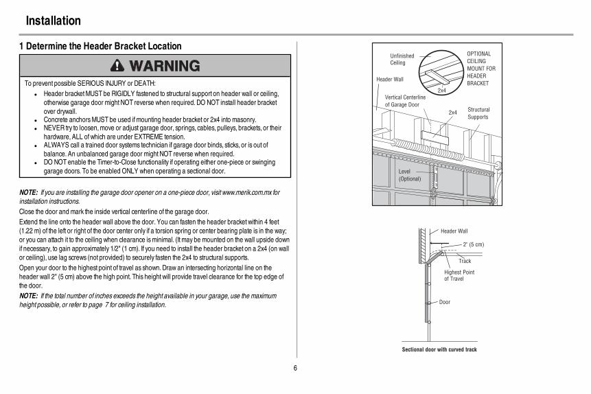
1 Determine the Header Bracket Location
To prevent possible SERIOUS INJURY or DEATH:l Header bracketMUST be RIGIDLY fastened to structural support on header wall or ceiling,
otherwise garage door might NOT reverse when required. DO NOT install header bracketover drywall.
l Concrete anchorsMUST be used if mounting header bracket or 2x4 into masonry.l NEVER try to loosen,move or adjust garage door, springs, cables, pulleys, brackets, or their
hardware, ALL of which are under EXTREME tension.l ALWAYS call a trained door systems technician if garage door binds, sticks, or is out of
balance. An unbalanced garage door might NOT reverse when required.l DO NOT enable the Timer-to-Close functionality if operating either one-piece or swinging
garage doors. To be enabled ONLY when operating a sectional door.
NOTE: If you are installing the garage door opener on a one-piece door, visit www.merik.com.mx forinstallation instructions.Close the door and mark the inside vertical centerline of the garage door.Extend the line onto the header wall above the door. You can fasten the header bracket within 4 feet(1.22 m) of the left or right of the door center only if a torsion spring or center bearing plate is in the way;or you can attach it to the ceiling when clearance isminimal. (It may be mounted on the wall upside downif necessary, to gain approximately 1/2" (1 cm). If you need to install the header bracket on a 2x4 (on wallor ceiling), use lag screws (not provided) to securely fasten the 2x4 to structural supports.Open your door to the highest point of travel as shown. Draw an intersecting horizontal line on theheader wall 2" (5 cm) above the high point. This height will provide travel clearance for the top edge ofthe door.NOTE: If the total number of inches exceeds the height available in your garage, use the maximumheight possible, or refer to page 7 for ceiling installation.
Header Wall
Unfinished Ceiling
Vertical Centerline
of Garage Door
2x4
2x4
Structural
Supports
Level
(Optional)
OPTIONAL
CEILING
MOUNT FOR
HEADER
BRACKET
Sectional door with curved track
Header Wall
Track
2" (5 cm)
Highest Point of Travel
Door
7
Installation
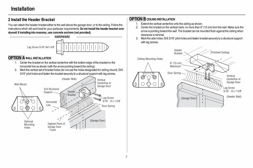
2 Install the Header BracketYou can attach the header bracket either to the wall above the garage door, or to the ceiling. Follow theinstructions which will work best for your particular requirements.Donot install the header bracket overdrywall. If installing intomasonry, use concrete anchors (not provided).
HARDWARE
Lag Screw 5/16"-9x1-5/8"
OPTION AWALL INSTALLATION1. Center the bracket on the vertical centerline with the bottom edge of the bracket on the
horizontal line as shown (with the arrow pointing toward the ceiling).2. Mark the vertical set of bracket holes (do not use the holes designated for ceiling mount). Drill
3/16" pilot holes and fasten the bracket securely to a structural support with lag screws.
Wall Mount
Optional Mounting Holes
Vertical Centerline of Garage Door
(Header Wall)
Header Bracket
2x4 Structural Support
Door Spring
(Garage Door)Highest Point of Garage Door
Travel
Horizontal Line
Lag Screw
5/16" - 9 x 1-5/8"
OPTION B CEILING INSTALLATION1. Extend the vertical centerline onto the ceiling as shown.2. Center the bracket on the vertical mark, no more than 6" (15 cm) from the wall. Make sure the
arrow is pointing toward the wall. The bracket can be mounted flush against the ceiling whenclearance isminimal.
3. Mark the side holes. Drill 3/16" pilot holes and fasten bracket securely to a structural supportwith lag screws.
(Header Wall)
Ceiling Mounting Holes
(Finished Ceiling)
Vertical Centerline of Garage Door
Header Bracket
6" (15 cm) Maximum
Door Spring
(Garage Door)
Lag Screw
5/16" - 9 x 1-5/8"

8
Installation
3 Attach the Rail to the Header Bracket1. Align the rail with the header bracket. Insert the clevis pin through the holes in the header
bracket and rail. Secure with the ring fastener.NOTE: Use the packing material as a protective base for the garage door opener.
HARDWARE
Clevis Pin 5/16" x 2-3/4" Ring Fastener
Ring
Fastener
Clevis Pin
5/16" X 2-3/4"
4 Position the Garage Door Opener
To prevent damage to garage door, rest garage door opener rail on 2x4 placed on top section ofdoor.
1. Remove the packing material and lift the garage door opener onto a ladder.2. Fully open the door and place a 2x4 (laid flat) under the rail.
A 2x4 is ideal for setting the distance between the rail and the door. If the ladder is not tall enough youwill need help at this point. If the door hits the trolley when it is raised, pull the trolley release arm down todisconnect the inner and outer trolley. Slide the outer trolley toward the garage door opener. The trolleycan remain disconnected until instructed.
Connected Disconnected

9
Installation
5 Hang the Garage Door Opener
To avoid possible SERIOUS INJURY from a falling garage door opener, fasten it SECURELY tostructural supports of the garage. Concrete anchorsMUST be used if installing ANY brackets intomasonry.
Hanging your garage door opener will vary depending on your garage. Two representative installationsare shown. Yoursmay be different. Hanging brackets should be angled (Figure 1) to provide rigidsupport. On finished ceilings (Figure 2), attach a sturdymetal bracket to structural supports beforeinstalling the opener. This bracket and fastening hardware are not provided.
1. Measure the distance from each side of the motor unit to the structural support.2. Cut both pieces of the hanging bracket to required lengths.3. Drill 3/16" pilot holes in the structural supports.4. Attach one end of each bracket to a support with 5/16"-18x1-7/8" lag screws (not provided).5. Fasten the opener to the hanging brackets with 5/16"-18x7/8" hex bolts, lock washers and
nuts.6. Check to make sure the rail is centered over the door (or in line with the header bracket if the
bracket is not centered above the door).7. Remove the 2x4. Operate the door manually. If the door hits the rail, raise the header bracket.
NOTE: DO NOT connect power to opener at this time.
FIGURE 1 FIGURE 2
(Not Provided)
Lag Screws
5/16"- 18x1-7/8"
Measure
Distance
Hex Bolt 5/16"- 18x7/8", Lock Washer 5/16", Nut 5/16"-18
FIGURE 3
Not Provided
Finished CeilingUnfinished Ceiling
Hex Bolt 5/16"- 18x7/8" Nut 5/16"-18 Lock Washer 5/16"
HARDWARE

10
Installation
6 Install the Light Bulbs
To prevent possible OVERHEATING of the end panel or light socket:l Use ONLY A19 incandescent (100W maximum) or compact fluorescent (26W maximum)
light bulbs.l DO NOT use incandescent bulbs larger than 100W.l DO NOT use compact fluorescent light bulbs larger than 26W (100W equivalent).l DO NOT use halogen bulbs.l DO NOT use short neck or specialty light bulbs.
1. Pull on the top center of the light lens and rotate the light lens down.2. Insert an A19 incandescent (100Wmaximum) or compact fluorescent (26W, 100W equivalent)
light bulb into the light socket.NOTE: DO NOT use halogen, short neck, or specialty light bulbs as these may overheat the end panelor light socket. DO NOT use LED bulbs as theymay reduce the range or performance of your remotecontrol(s).
3. Rotate the lens up to close.
or or
7 Attach the Emergency Release Rope and Handle
To prevent possible SERIOUS INJURY or DEATH from a falling garage door:l If possible, use emergency release handle to disengage trolleyONLY when garage door is
CLOSED.Weak or broken springs or unbalanced door could result in an open door fallingrapidly and/or unexpectedly.
l NEVER use emergency release handle unless garage doorway is clear of persons andobstructions.
l NEVER use handle to pull door open or closed. If rope knot becomes untied, you could fall.
1. Insert one end of the emergency release rope through the handle.Make sure that “NOTICE” isright side up. Tie a knot at least 1 inch (2.5 cm) from the end of the emergency release rope.
2. Insert the other end of the emergency release rope through the hole in the trolley release arm.Mount the emergency release within reach, but at least 6 feet (1.83 m) above the floor,avoiding contact with vehicles to prevent accidental release and secure with a knot.
NOTE: If it is necessary to cut the emergency release rope, seal the cut end with a match or lighter toprevent unraveling. Ensure the emergency release rope and handle are above the top of all vehicles toavoid entanglement.
Trolley
Release Arm
11
Installation
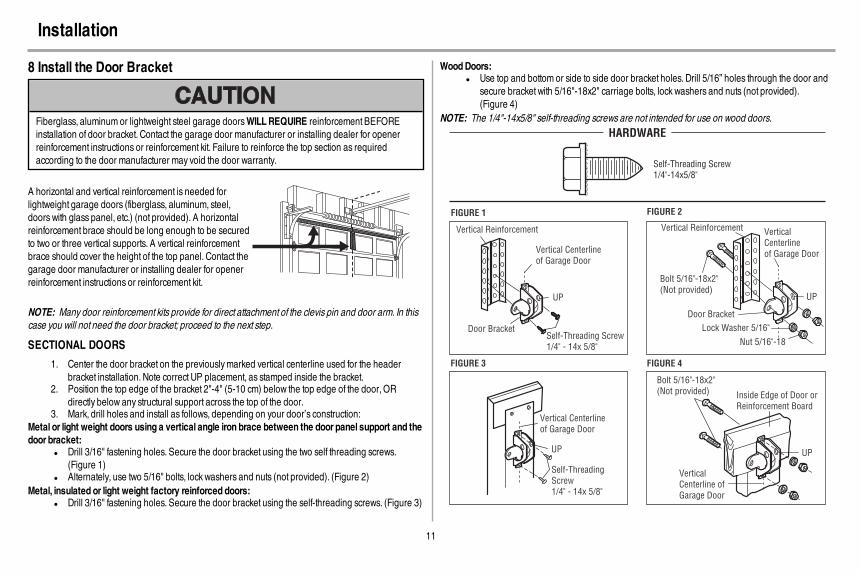
8 Install the Door Bracket
Fiberglass, aluminum or lightweight steel garage doorsWILLREQUIRE reinforcement BEFOREinstallation of door bracket. Contact the garage door manufacturer or installing dealer for openerreinforcement instructions or reinforcement kit. Failure to reinforce the top section as requiredaccording to the door manufacturer may void the door warranty.
A horizontal and vertical reinforcement is needed forlightweight garage doors (fiberglass, aluminum, steel,doors with glass panel, etc.) (not provided). A horizontalreinforcement brace should be long enough to be securedto two or three vertical supports. A vertical reinforcementbrace should cover the height of the top panel. Contact thegarage door manufacturer or installing dealer for openerreinforcement instructions or reinforcement kit.
NOTE: Many door reinforcement kits provide for direct attachment of the clevis pin and door arm. In thiscase you will not need the door bracket; proceed to the next step.
SECTIONAL DOORS
1. Center the door bracket on the previouslymarked vertical centerline used for the headerbracket installation. Note correct UP placement, as stamped inside the bracket.
2. Position the top edge of the bracket 2"-4" (5-10 cm) below the top edge of the door, ORdirectly below any structural support across the top of the door.
3. Mark, drill holes and install as follows, depending on your door’s construction:Metal or light weight doors using a vertical angle iron brace between the door panel support and thedoor bracket:
l Drill 3/16" fastening holes. Secure the door bracket using the two self threading screws.(Figure 1)
l Alternately, use two 5/16" bolts, lock washers and nuts (not provided). (Figure 2)Metal, insulated or light weight factory reinforced doors:
l Drill 3/16" fastening holes. Secure the door bracket using the self-threading screws. (Figure 3)
WoodDoors:l Use top and bottom or side to side door bracket holes. Drill 5/16” holes through the door and
secure bracket with 5/16"-18x2" carriage bolts, lock washers and nuts (not provided).(Figure 4)
NOTE: The 1/4"-14x5/8" self-threading screws are not intended for use on wood doors.
FIGURE 1
FIGURE 3
Vertical Reinforcement
Vertical Centerline
of Garage Door
UP
Door BracketSelf-Threading Screw
1/4" - 14x 5/8"
Self-Threading
Screw
1/4" - 14x 5/8"
Vertical Centerline
of Garage Door
UP
FIGURE 4
Vertical
Centerline of
Garage Door
Bolt 5/16"-18x2"
(Not provided)
UP
Inside Edge of Door or
Reinforcement Board
FIGURE 2
Vertical Reinforcement
Bolt 5/16"-18x2"
(Not provided)
Lock Washer 5/16"
Nut 5/16"-18
Door Bracket
UP
Vertical
Centerline
of Garage Door
Self-Threading Screw
1/4"-14x5/8"
HARDWARE
12
Installation
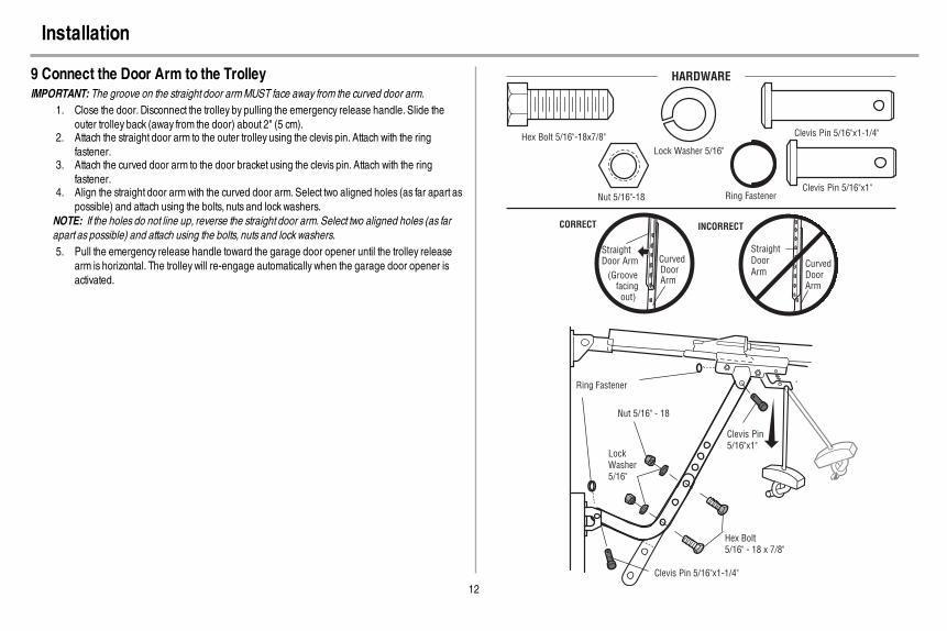
9 Connect the Door Arm to the TrolleyIMPORTANT: The groove on the straight door armMUST face away from the curved door arm.
1. Close the door. Disconnect the trolley by pulling the emergency release handle. Slide theouter trolley back (away from the door) about 2" (5 cm).
2. Attach the straight door arm to the outer trolley using the clevis pin. Attach with the ringfastener.
3. Attach the curved door arm to the door bracket using the clevis pin. Attach with the ringfastener.
4. Align the straight door armwith the curved door arm. Select two aligned holes (as far apart aspossible) and attach using the bolts, nuts and lock washers.
NOTE: If the holes do not line up, reverse the straight door arm. Select two aligned holes (as farapart as possible) and attach using the bolts, nuts and lock washers.5. Pull the emergency release handle toward the garage door opener until the trolley release
arm is horizontal. The trolley will re-engage automatically when the garage door opener isactivated.
Straight Door Arm Curved
DoorArm
(Groove facing out)
CORRECT
StraightDoorArm
Curved Door Arm
INCORRECT
Clevis Pin 5/16"x1-1/4"
Ring Fastener
Clevis Pin5/16"x1"
Nut 5/16" - 18
Lock Washer5/16"
Hex Bolt 5/16" - 18 x 7/8"
HARDWARE
Hex Bolt 5/16"-18x7/8"
Nut 5/16"-18
Lock Washer 5/16"
Clevis Pin 5/16"x1"
Clevis Pin 5/16"x1-1/4"
Ring Fastener

13
Install the Door Control
1 Install the Door Control
To prevent possible SERIOUS INJURY or DEATH from electrocution:l Be sure power is NOT connected BEFORE installing door control.l Connect ONLY to 12 VOLT low voltage wires.
To prevent possible SERIOUS INJURY or DEATH from a closing garage door:l Install door control within sight of garage door, out of reach of children at a minimum height of
5 feet (1.5 m), and away fromALL moving parts of door.l NEVER permit children to operate or play with door control push buttons or remote control
transmitters.l Activate door ONLY when it can be seen clearly, is properly adjusted, and there are no
obstructions to door travel.l ALWAYS keep garage door in sight until completely closed. NEVER permit anyone to cross
path of closing garage door.
INTRODUCTIONCompatible with MyQ® and Security+ 2.0® accessories, see page 36. Your garage door opener iscompatible with up to 2 Smart Control Panels or 4 of any other Security+ 2.0® door controls.NOTE: Older LiftMaster door controls and third party products are not compatible.Install the door control within sight of the door at a minimum height of 5 feet (1.5 m) where small childrencannot reach, and away from the moving parts of the door. For gang box installations it is not necessaryto drill holes or install the drywall anchors. Use the existing holes in the gang box.NOTE: Your productmay look different than the illustrations.
HARDWARE
Screw6ABx1" (2)
Drywall Anchors (2)
Screw6-32x1" (2)
1. Strip 7/16 inch (11 mm) of insulation from one end of the wire and separate the wires.2. Connect one wire to each of the two screws on the back of the door control. The wires can be
connected to either screw.PRE-WIRED INSTALLATIONS: Choose any two wires to connect, note which wires are usedso the correct wires are connected at the garage door opener in a later step.
3. Mark the location of the bottommounting hole and drill a 5/32 inch (4 mm) hole.4. Install the bottom screw, allowing 1/8 inch (3 mm) to protrude from the wall.5. Position the bottom hole of the door control over the screw and slide down into place.6. Lift the push bar up and mark the top hole.7. Remove the door control from the wall and drill a 5/32 inch (4 mm) hole for the top screw.8. Position the bottom hole of the door control over the screw and slide down into place. Attach
the top screw.
7/16" (11 mm) Wall
1 2 3
DRYWALLGANG BOX
6ABx1"
6-32x1"Drywall Anchor
4-5 6
6-32x1"
GANG BOX
8 DRYWALL
6ABx1"
Drywall Anchor
7
14
Install the Door Control
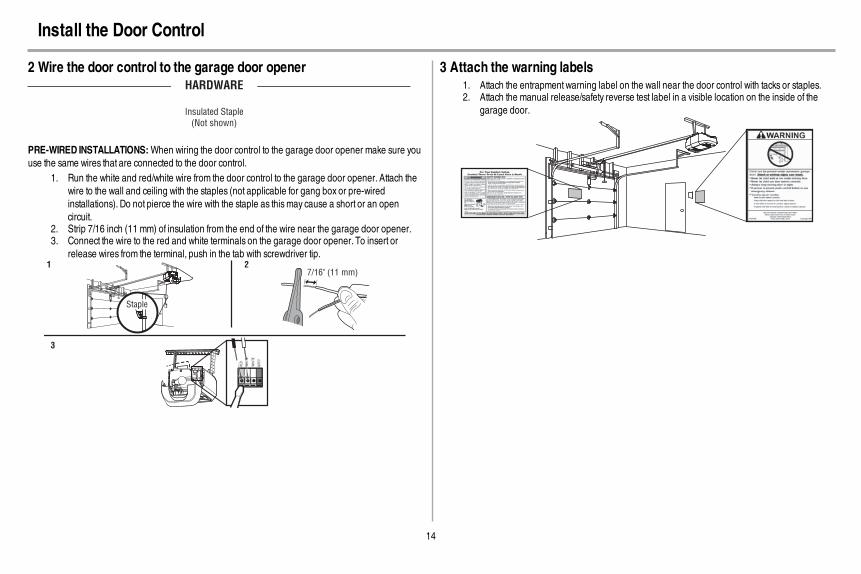
2 Wire the door control to the garage door openerHARDWARE
Insulated Staple
(Not shown)
PRE-WIRED INSTALLATIONS:When wiring the door control to the garage door opener make sure youuse the same wires that are connected to the door control.
1. Run the white and red/white wire from the door control to the garage door opener. Attach thewire to the wall and ceiling with the staples (not applicable for gang box or pre-wiredinstallations). Do not pierce the wire with the staple as thismay cause a short or an opencircuit.
2. Strip 7/16 inch (11 mm) of insulation from the end of the wire near the garage door opener.3. Connect the wire to the red and white terminals on the garage door opener. To insert or
release wires from the terminal, push in the tab with screwdriver tip.
7/16" (11 mm) 2
3
1
Staple
WH
ITE
RE
D
WH
ITE
GR
EY
3 Attach the warning labels1. Attach the entrapment warning label on the wall near the door control with tacks or staples.2. Attach the manual release/safety reverse test label in a visible location on the inside of the
garage door.
15
Install the Protector System®
Introduction
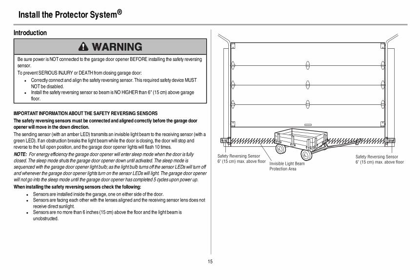
Be sure power is NOT connected to the garage door opener BEFORE installing the safety reversingsensor.To prevent SERIOUS INJURY or DEATH from closing garage door:
l Correctly connect and align the safety reversing sensor. This required safety device MUSTNOT be disabled.
l Install the safety reversing sensor so beam is NO HIGHER than 6" (15 cm) above garagefloor.
IMPORTANT INFORMATIONABOUTTHE SAFETY REVERSING SENSORSThe safety reversing sensors must be connected and aligned correctly before the garage dooropenerwillmove in the down direction.The sending sensor (with an amber LED) transmits an invisible light beam to the receiving sensor (with agreen LED). If an obstruction breaks the light beamwhile the door is closing, the door will stop andreverse to the full open position, and the garage door opener lights will flash 10 times.NOTE: For energy efficiency the garage door opener will enter sleep mode when the door is fullyclosed. The sleep mode shuts the garage door opener down until activated. The sleep mode issequenced with the garage door opener light bulb; as the light bulb turns off the sensor LEDswill turn offand whenever the garage door opener lights turn on the sensor LEDswill light. The garage door openerwill not go into the sleep mode until the garage door opener has completed 5 cycles upon power up.When installing the safety reversing sensors check the following:
l Sensors are installed inside the garage, one on either side of the door.l Sensors are facing each other with the lenses aligned and the receiving sensor lens does not
receive direct sunlight.l Sensors are no more than 6 inches (15 cm) above the floor and the light beam is
unobstructed.
Invisible Light BeamProtection Area
Safety Reversing Sensor6" (15 cm) max. above floor
Safety Reversing Sensor6" (15 cm) max. above floor
16
Install the Protector System®
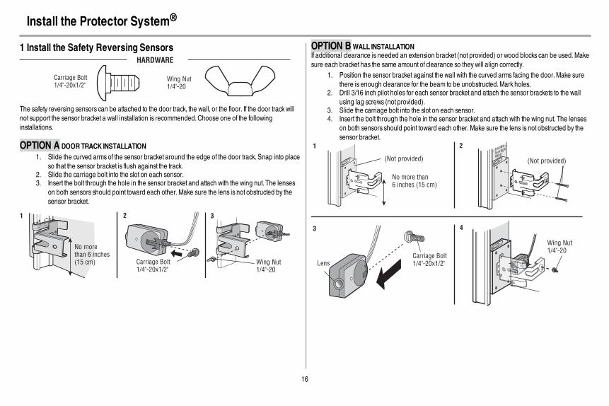
1 Install the Safety Reversing SensorsHARDWARE
Carriage Bolt1/4"-20x1/2"
Wing Nut1/4"-20
The safety reversing sensors can be attached to the door track, the wall, or the floor. If the door track willnot support the sensor bracket a wall installation is recommended. Choose one of the followinginstallations.
OPTION A DOORTRACK INSTALLATION1. Slide the curved arms of the sensor bracket around the edge of the door track. Snap into place
so that the sensor bracket is flush against the track.2. Slide the carriage bolt into the slot on each sensor.3. Insert the bolt through the hole in the sensor bracket and attach with the wing nut. The lenses
on both sensors should point toward each other. Make sure the lens is not obstructed by thesensor bracket.
No morethan 6 inches(15 cm) Carriage Bolt
1/4"-20x1/2" Wing Nut1/4"-20
1 2 3
OPTION BWALL INSTALLATIONIf additional clearance is needed an extension bracket (not provided) or wood blocks can be used.Makesure each bracket has the same amount of clearance so they will align correctly.
1. Position the sensor bracket against the wall with the curved arms facing the door.Make surethere is enough clearance for the beam to be unobstructed.Mark holes.
2. Drill 3/16 inch pilot holes for each sensor bracket and attach the sensor brackets to the wallusing lag screws (not provided).
3. Slide the carriage bolt into the slot on each sensor.4. Insert the bolt through the hole in the sensor bracket and attach with the wing nut. The lenses
on both sensors should point toward each other. Make sure the lens is not obstructed by thesensor bracket.
(Not provided)
No more than 6 inches (15 cm)
1 2Inside
Garage
Wall
(Not provided)
LensCarriage Bolt1/4"-20x1/2"
Wing Nut1/4"-20
3 4

17
Install the Protector System®
OPTION C FLOOR INSTALLATIONUse an extension bracket (not provided) or wood block to raise the sensor bracket if needed.
1. Carefully measure the position of both sensor brackets so they will be the same distance fromthe wall and unobstructed.
2. Attach the sensor brackets to the floor using concrete anchors (not provided).3. Slide the carriage bolt into the slot on each sensor.4. Insert the bolt through the hole in the sensor bracket and attach with the wing nut. The lens on
both sensors should point toward each other. Make sure the lens is not obstructed by thesensor bracket.
Inside
Garage
Wall
(Not provided)1 2
Carriage Bolt
1/4"-20x1/2"
Wing Nut
1/4"-20
3 4
2 Wire the Safety Reversing SensorsPRE-WIRED INSTALLATIONS: If your garage already haswires installed for the safety reversingsensors, see page 18.
HARDWARE
Insulated Staple
(Not shown)
OPTION A INSTALLATION WITHOUT PRE-WIRING1. Run the wire from both sensors to the garage door opener. Attach the wire to the wall and
ceiling with the staples.2. Strip 7/16 inch (11 mm) of insulation from each set of wires. Separate the wires. Twist the white
wires together. Twist the white/black wires together.3. Insert the white wires into the white terminal on the garage door opener. Insert the white/black
wires into the grey terminal on the garage door opener. To insert or remove the wires from theterminal, push in the tab with a screwdriver tip.
1 2
3
Staple
DR
ED
WRE
7/16" (11 mm)
18
Install the Protector System®
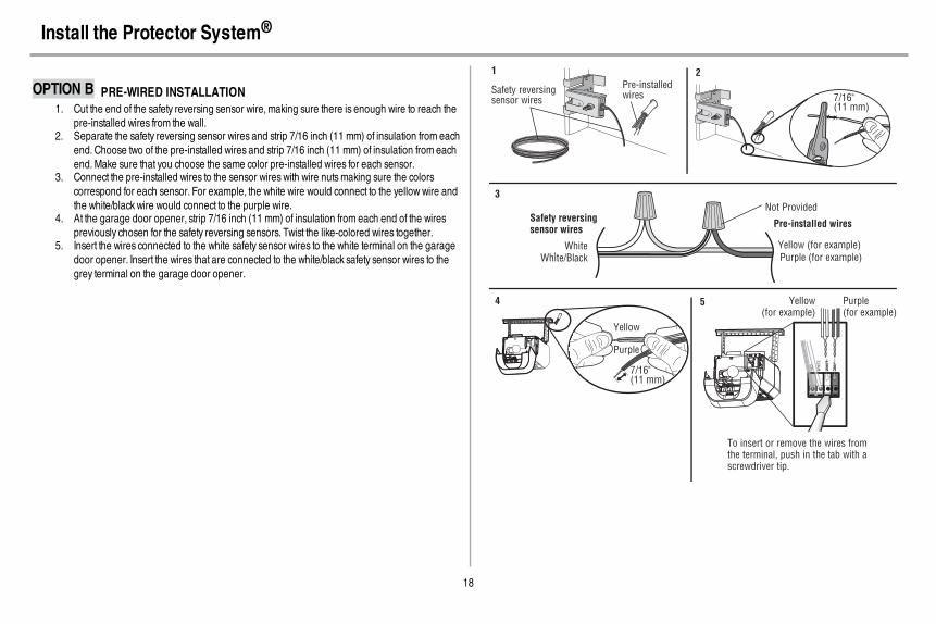
OPTION B PRE-WIRED INSTALLATION1. Cut the end of the safety reversing sensor wire,making sure there is enough wire to reach the
pre-installed wires from the wall.2. Separate the safety reversing sensor wires and strip 7/16 inch (11 mm) of insulation from each
end. Choose two of the pre-installed wires and strip 7/16 inch (11 mm) of insulation from eachend.Make sure that you choose the same color pre-installed wires for each sensor.
3. Connect the pre-installed wires to the sensor wires with wire nutsmaking sure the colorscorrespond for each sensor. For example, the white wire would connect to the yellowwire andthe white/black wire would connect to the purple wire.
4. At the garage door opener, strip 7/16 inch (11 mm) of insulation from each end of the wirespreviously chosen for the safety reversing sensors. Twist the like-colored wires together.
5. Insert the wires connected to the white safety sensor wires to the white terminal on the garagedoor opener. Insert the wires that are connected to the white/black safety sensor wires to thegrey terminal on the garage door opener.
Safety reversing sensor wires
Pre-installed wires
WhiteWhite/Black
Yellow (for example)
Purple (for example)
Not Provided
Pre-installed wires Safety reversing sensor wires
7/16"(11 mm)
Yellow
Purple
1
3
4
7/16" (11 mm)
2
Yellow(for example)
Purple(for example)
To insert or remove the wires from the terminal, push in the tab with a screwdriver tip.
5
RE
D
WH
ITE
WH
ITE
GR
EY
D
WRE
DR
E
WH
ITE
WH
ITE
GR
EY
GR
EY

19
Power
1 Connect Power
To prevent possible SERIOUS INJURY or DEATH from electrocution or fire:l Be sure power is NOT connected to the opener, and disconnect power to circuit BEFORE
removing cover to establish permanent wiring connection.l Garage door installation and wiring MUST be in compliance with ALL local electrical and
building codes.l NEVER use an extension cord, 2-wire adapter, or change plug in ANY way to make it fit
outlet. Be sure the opener is grounded.
To avoid installation difficulties, do not activatethe garage door opener at this time.To reduce the risk of electric shock, your garagedoor opener has a grounding type plug with a thirdgrounding pin. This plug will only fit into agrounding type outlet. If the plug doesn’t fit into youroutlet, contact a qualified electrician to install theproper outlet.
THERE ARE TWO OPTIONS FORCONNECTING POWER:
1. Plug in the garage door opener into agrounded outlet.
2. DO NOT run garage door opener at thistime.
TYPICAL WIRING
If permanent wiring is required by your local code, refer to the following procedure. To make apermanent connection through the 7/8 inch hole in the top of the motor unit (according to local code):
Wiring through a filter board (Models manufactured beforeOctober 2012):
1. Be sure power is NOT connected to the opener,and disconnect power to circuit.
2. Remove the garage door opener cover and setaside.
3. Remove the attached green ground terminal.4. Cut black and white wires. Strip away 1/2 inch
(1 cm) of insulation, 3 inches (7.5 cm) before spadeterminals.
5. Remove the power cord from opener.6. Install a conduit or flex cable adapter to the 7/8 inch
hole.7. Run wires through conduit, cut to proper length and
strip insulation.8. Attach with wire nuts provided. Attach the ground
wire to the green ground screw. The opener mustbe grounded.
9. Properly secure wire under plastic ties so that wiredoes not come in contact with moving parts.
10. Reinstall the cover. DO NOT run garage dooropener at this time.
Ground Tab
Green Ground
Screw
Ground Wire
Black Wire
White Wire
PERMANENT WIRING
Wire Nuts
Wiring through a terminal block (Models manufacturedafter October 2012):
1. Remove the motor unit cover screws and set thecover aside.
2. Remove the attached 3-prong cord.3. Connect the black (line) wire to the screw on the
brass terminal; the white (neutral) wire to the screwon the silver terminal; and the ground wire to thegreen ground screw.The openermust begrounded.
4. Reinstall the cover.
Ground Tab
Green
Ground
Screw
Ground
Wire
White Wire
PERMANENT WIRING
Black
Wire
Black
Wire
20
Power
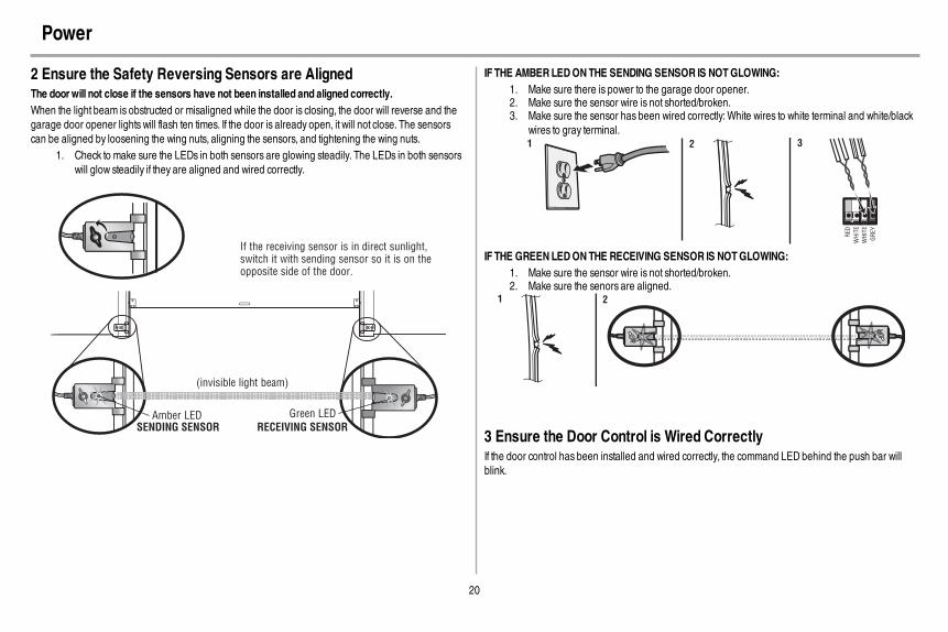
2 Ensure the Safety Reversing Sensors are AlignedThe doorwill not close if the sensors have not been installed and aligned correctly.When the light beam is obstructed or misaligned while the door is closing, the door will reverse and thegarage door opener lights will flash ten times. If the door is already open, it will not close. The sensorscan be aligned by loosening the wing nuts, aligning the sensors, and tightening the wing nuts.
1. Check to make sure the LEDs in both sensors are glowing steadily. The LEDs in both sensorswill glow steadily if they are aligned and wired correctly.
Green LEDAmber LED
If the receiving sensor is in direct sunlight, switch it with sending sensor so it is on the opposite side of the door.
(invisible light beam)
SENDING SENSOR RECEIVING SENSOR
IF THE AMBERLEDONTHE SENDING SENSOR IS NOTGLOWING:1. Make sure there is power to the garage door opener.2. Make sure the sensor wire is not shorted/broken.3. Make sure the sensor has been wired correctly:White wires to white terminal and white/black
wires to gray terminal.
RE
D
WH
ITE
WH
ITE
GR
EY
321
IF THE GREENLEDONTHE RECEIVING SENSOR IS NOTGLOWING:1. Make sure the sensor wire is not shorted/broken.2. Make sure the senors are aligned.
1 2
3 Ensure the Door Control is Wired CorrectlyIf the door control has been installed and wired correctly, the command LED behind the push bar willblink.

21
Adjustments
Introduction
Without a properly installed safety reversal system, persons (particularly small children) could beSERIOUSLY INJURED or KILLED by a closing garage door.
l Incorrect adjustment of garage door travel limits will interfere with proper operation ofsafety reversal system.
l After ANY adjustments are made, the safety reversal systemMUST be tested. Door MUSTreverse on contact with 1-1/2" (3.8 cm) high object (or 2x4 laid flat) on floor.
To prevent damage to vehicles, be sure fully open door provides adequate clearance.
Your garage door opener is designed with electronic controls to make setup and adjustments easy. Theadjustments allow you to programwhere the door will stop in the open (UP) and close (DOWN) position.The electronic controls sense the amount of force required to open and close the door. The force isadjusted automatically when you program the travel.NOTE: If anything interferes with the door’s upward travel it will stop. If anything interferes with the door’sdownward travel, it will reverse.
UP (Open) DOWN (Close)
PROGRAMMING BUTTONS
The programming buttons are located on the left side panel of the garage door opener and are used toprogram the travel.While programming, the UP and DOWNbuttons can be used to move the door asneeded.
UP Button
Adjustment Button
DOWN Button
PROGRAMMING BUTTONS

22
Adjustments
1 Program the Travel
Without a properly installed safety reversal system, persons (particularly small children) could beSERIOUSLY INJURED or KILLED by a closing garage door.
l Incorrect adjustment of garage door travel limits will interfere with proper operation ofsafety reversal system.
l After ANY adjustments are made, the safety reversal systemMUST be tested. Door MUSTreverse on contact with 1-1/2" (3.8 cm) high object (or 2x4 laid flat) on floor.
While programming, the UP and DOWNbuttons can be used to move the door as needed.1. Press and hold the Adjustment Button until the UP Button begins to flash and/or a beep is
heard.2. Press and hold the UP Button until the door is in the desired UP position.3. Once the door is in the desired UP position press and release the Adjustment Button. The
garage door opener lights will flash twice and the DOWNButton will begin to flash.4. Press and hold the DOWNButton until the door is in the desired DOWNposition.5. Once the door is in the desired DOWNposition press and release the Adjustment Button. The
garage door opener lights will flash twice and the UP Button will begin to flash.6. Press and release the UP Button.When the door travels to the programmed UP position, the
DOWNButton will begin to flash.7. Press and release the DOWNButton. The door will travel to the programmed DOWNposition.
Programming is complete.If the garage door opener lights are flashing 5 times during the steps for Program the Travel, theprogramming has timed out. If the garage door opener lights are flashing 10 times during the steps forProgram the Travel, the safety reversing sensors are misaligned or obstructed (refer to page 20).Whenthe sensors are aligned and unobstructed, cycle the door through a complete up and down cycle usingthe remote control or the UP and DOWNbuttons. Programming is complete. If you are unable to operatethe door up and down, repeat the steps for Programming the Travel.
UP Button
Adjustment Button
DOWN Button
PROGRAMMING BUTTONS
1 2 3
4 5
6 7
23
Adjustments
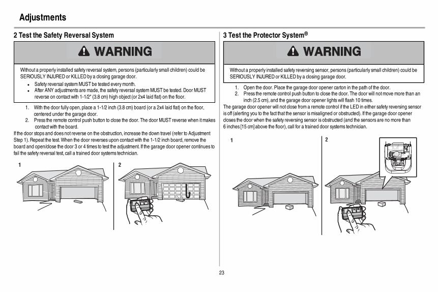
2 Test the Safety Reversal System
Without a properly installed safety reversal system, persons (particularly small children) could beSERIOUSLY INJURED or KILLED by a closing garage door.
l Safety reversal systemMUST be tested everymonth.l After ANY adjustments are made, the safety reversal systemMUST be tested. Door MUST
reverse on contact with 1-1/2" (3.8 cm) high object (or 2x4 laid flat) on the floor.
1. With the door fully open, place a 1-1/2 inch (3.8 cm) board (or a 2x4 laid flat) on the floor,centered under the garage door.
2. Press the remote control push button to close the door. The door MUST reverse when it makescontact with the board.
If the door stops and does not reverse on the obstruction, increase the down travel (refer to AdjustmentStep 1). Repeat the test.When the door reverses upon contact with the 1-1/2 inch board, remove theboard and open/close the door 3 or 4 times to test the adjustment. If the garage door opener continues tofail the safety reversal test, call a trained door systems technician.
1 2
3 Test the Protector System®
Without a properly installed safety reversing sensor, persons (particularly small children) could beSERIOUSLY INJURED or KILLED by a closing garage door.
1. Open the door. Place the garage door opener carton in the path of the door.2. Press the remote control push button to close the door. The door will notmove more than an
inch (2.5 cm), and the garage door opener lights will flash 10 times.The garage door opener will not close from a remote control if the LED in either safety reversing sensoris off (alerting you to the fact that the sensor ismisaligned or obstructed). If the garage door openercloses the door when the safety reversing sensor is obstructed (and the sensors are no more than6 inches [15 cm] above the floor), call for a trained door systems technician.
1 2
24
Battery Backup
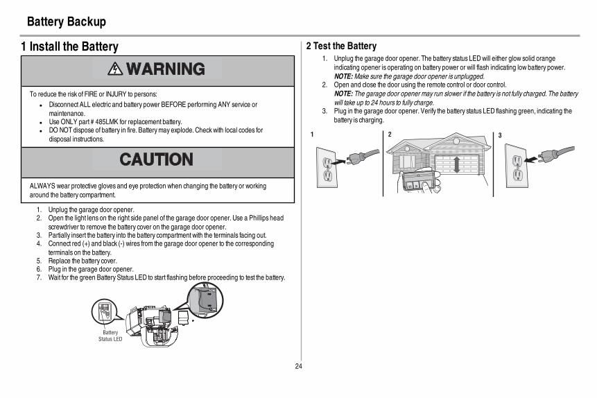
1 Install the Battery
To reduce the risk of FIRE or INJURY to persons:l Disconnect ALL electric and battery power BEFORE performing ANY service or
maintenance.l Use ONLY part # 485LMK for replacement battery.l DO NOT dispose of battery in fire. Batterymay explode. Checkwith local codes for
disposal instructions.
ALWAYS wear protective gloves and eye protection when changing the battery or workingaround the battery compartment.
1. Unplug the garage door opener.2. Open the light lens on the right side panel of the garage door opener. Use a Phillips head
screwdriver to remove the battery cover on the garage door opener.3. Partially insert the battery into the battery compartment with the terminals facing out.4. Connect red (+) and black (-) wires from the garage door opener to the corresponding
terminals on the battery.5. Replace the battery cover.6. Plug in the garage door opener.7. Wait for the green Battery Status LED to start flashing before proceeding to test the battery.
Battery
Status LED
2 Test the Battery1. Unplug the garage door opener. The battery status LEDwill either glow solid orange
indicating opener is operating on battery power or will flash indicating low battery power.NOTE:Make sure the garage door opener is unplugged.
2. Open and close the door using the remote control or door control.NOTE: The garage door opener may run slower if the battery is not fully charged. The batterywill take up to 24 hours to fully charge.
3. Plug in the garage door opener. Verify the battery status LED flashing green, indicating thebattery is charging.
1 2 3
25
Battery Backup
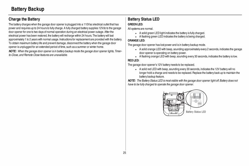
Charge the BatteryThe battery charges when the garage door opener is plugged into a 110Vac electrical outlet that haspower and requires up to 24 hours to fully charge. A fully charged battery supplies 12Vdc to the garagedoor opener for one to two days of normal operation during an electrical power outage. After theelectrical power has been restored, the battery will recharge within 24 hours. The battery will lastapproximately 1 to 2 years with normal usage. Instructions for replacement are provided with the battery.To obtain maximum battery life and prevent damage, disconnect the battery when the garage dooropener is unplugged for an extended period of time, such as a summer or winter home.NOTE: When the garage door opener is in battery backup mode the garage door opener lights, Timer-to-Close, and Remote Close features are unavailable.
Battery Status LEDGREENLED:All systems are normal.
l A solid green LED light indicates the battery is fully charged.l A flashing green LED indicates the battery is being charged.
ORANGE LED:The garage door opener has lost power and is in battery backup mode.
l A solid orange LEDwith beep, sounding approximately every 2 seconds, indicates the garagedoor opener is operating on battery power.
l A flashing orange LEDwith beep, sounding every 30 seconds, indicates the battery is low.REDLED:The garage door opener's 12V battery needs to be replaced.
l A solid red LEDwith beep, sounding every 30 seconds, indicates the 12V battery will nolonger hold a charge and needs to be replaced. Replace the battery back up to maintain thebattery backup feature.
NOTE: The Battery Status LED ismost visible with the garage door opener light off. Battery does nothave to be fully charged to operate the garage door opener.
Battery Status LED

26
IMPORTANT SAFETY INSTRUCTIONS
WARNING
To reduce the risk of SEVERE INJURY or DEATH:1. READANDFOLLOWALL WARNINGS AND INSTRUCTIONS.2. ALWAYS keep remote controls out of reach of children. NEVER permit children to operate or
play with garage door control push buttons or remote controls.3. ONLY activate garage door when it can be seen clearly, it is properly adjusted, and there are
no obstructions to door travel.4. ALWAYS keep garage door in sight and away from people and objects until completely
closed. NO ONE SHOULDCROSS THE PATHOFTHE MOVING DOOR.5. NO ONE SHOULDGO UNDERA STOPPED, PARTIALLY OPENEDDOOR.6. If possible, use emergency release handle to disengage trolleyONLY when garage door is
CLOSED.Use caution when using this release with the door open.Weak or broken springs orunbalanced door could result in an open door falling rapidly and/or unexpectedly andincreasing the risk of SEVERE INJURY or DEATH.
7. NEVER use emergency release handle unless garage doorway is clear of persons andobstructions.
8. NEVER use handle to pull garage door open or closed. If rope knot becomes untied, youcould fall.
9. After ANY adjustments are made, the safety reversal systemMUST be tested.
10. Safety reversal systemMUST be tested everymonth. Garage door MUST reverse oncontact with 1-1/2" (3.8 cm) high object (or a 2x4 laid flat) on the floor. Failure to adjust thegarage door opener properly increases the risk of SEVERE INJURY or DEATH.
11. ALWAYS KEEP GARAGE DOORPROPERLY BALANCED (see page 1). An improperlybalanced door mayNOT reverse when required and could result in SEVERE INJURY orDEATH.
12. ALL repairs to cables, spring assemblies and other hardware, ALL of which are underEXTREME tension,MUST be made by a trained door systems technician.
13. To avoid SERIOUS PERSONAL INJURY or DEATH from electrocution, disconnect ALLelectric and battery power BEFORE performing ANY service or maintenance.
14. This operator system is equipped with an unattended operation feature. The door couldmove unexpectedly. NO ONE SHOULDCROSS THE PATHOFTHE MOVING DOOR.
15. DO NOT enable the Timer-to-Close functionality if operating either one-piece or swinginggarage doors. To be enabled ONLY when operating a sectional door.
16. SAVE THESE INSTRUCTIONS.
Operation

27
Features
Your garage door opener is equipped with features to provide you with greater control over your garagedoor operation.
Alert2CloseThe Alert2Close feature provides a visual and an audible alert that an unattended door is closing.TIMER-TO-CLOSE (TTC)The TTC feature automatically closes the door after a specified time period that can be adjusted using aTTC enabled door control. Prior to and during the door closing the garage door opener lights will flashand the garage door opener will beep.MyQ®
MyQ® technology uses a 900MHz signal to provide two-way communication between the garage dooropener and MyQ® enabled accessories. Your garage door opener is compatible with up to 16 MyQ®
accessories.SECURITY+ 2.0® REMOTE CONTROLS AND DOOR CONTROLSYour garage door opener has already been programmed at the factory to operate with your remotecontrol, which changeswith each use, randomly accessing over 100 billion new codes. Compatible withMyQ® and Security+ 2.0® accessories, see page 36.NOTE: Older LiftMaster remote controls, door controls, and third party products are not compatible.
SECURITY+ 2.0®
AccessoriesMemory Capacity
Remote Controls Up to 24
DoorControls Up to 2 Smart Control Panels or 4 of any other Security+ 2.0® door controls
Keyless Entries Up to 2
THE PROTECTORSYSTEM® (SAFETY REVERSING SENSORS)When properly connected and aligned, the safety reversing sensors will detect an obstruction in the pathof the infrared beam. If an obstruction breaks the infrared beamwhile the door is closing, the door willstop and reverse to full open position, and the opener lights will flash 10 times. If the door is fully open,and the safety reversing sensors are not installed, or are misaligned, the door will not close from aremote control. However, you can close the door if you hold the button on the door control or keylessentry until the door is fully closed. The safety reversing sensors do not affect the opening cycle.
ENERGY CONSERVATIONFor energy efficiency the garage door opener will enter sleep mode when the door is fully closed. Thesleep mode shuts the garage door opener down until activated. The sleep mode is sequenced with thegarage door opener light bulb; as the light bulb turns off the sensor LEDswill turn off and whenever thegarage door opener lights turn on the sensor LEDswill light. The garage door opener will not go into thesleep mode until the garage door opener has completed 5 cycles upon power up.LIGHTSThe garage door opener light bulbs will turn on when the opener is initially plugged in; power is restoredafter interruption, or when the garage door opener is activated. The lights will turn off automatically after4-1/2 minutes. An incandescent A19 light bulb (100 watt maximum) or for maximum energy efficiency a26W (100W equivalent) compact fluorescent light (CFL) bulb may be used.Light FeatureThe garage door opener is equipped with an added feature; the lights will turn on when someone entersthrough the open garage door and the safety reversing sensor infrared beam is broken. For addedcontrol over the light bulbs on your garage door opener, see page 29.USING YOURGARAGE DOOROPENERThe garage door opener can be activated through a wall-mounted door control, remote control, wirelesskeyless entry or MyQ® accessory.When the door is closed and the garage door opener is activated thedoor will open. If the door senses an obstruction or is interrupted while opening the door will stop.Whenthe door is in any position other than closed and the garage door opener is activated the door will close.If the garage door opener senses an obstruction while closing, the door will reverse. If the obstructioninterrupts the sensor beam the garage door opener lights will blink 10 times. However, you can close thedoor if you hold the button on the door control or keyless entry until the door is fully closed. The safetyreversing sensors do not affect the opening cycle. The safety reversing sensor must be connected andaligned correctly before the garage door opener will move in the down direction.BATTERY BACKUPThe battery backup system allows access in and out of your garage, even when the power is out.Whenthe garage door opener is operating on battery power, the garage door opener will run slower, the lightwill not function, the Battery Status LEDwill glow solid orange, and a beep will sound approximatelyevery 2 seconds.

28
Door Control
Using the Door ControlSYNCHRONIZE THE DOOR CONTROL
To synchronize the door control to the garage door opener, press the push bar until the garage dooropener activates (it may take up to 3 presses). Test the door control by pressing the push bar, eachpress of the push bar will activate the garage door opener.
Push Bar
LIGHT Button
Motion Sensor
LOCK Button
COMMAND LED
LEARN Button
SERVICE LED
PUSH BAR
Press the push bar to open or close the door.
LIGHT BUTTON
Press the LIGHT button to turn the garage door opener lights on or off.When the lights are turned onthey will stay on until the LIGHT button is pressed again, or until the garage door opener is activated.Once the garage door opener is activated the lights will turn off after the specified period of time (thefactory setting is 4-1/2 minutes). The LIGHT button will not control the lights when the door is in motion.
The following features are accessible by lifting up the push bar:LEARNADEVICEAny compatible remote controls, wireless keyless entry, or MyQ® accessories can be programmed to thegarage door opener by pressing the LEARN button on the Motion Detecting Control Panel, see page 30.
LOCKThe LOCK feature is designed to prevent activation of the garage door opener from remote controlswhile still allowing activation from the door control and keyless entry. This feature is useful for addedpeace ofmind when the home is empty (i.e. vacation).AUTOMATIC LIGHTMotion Sensor (Premium Motion -DetectingControl Panel)Factory default is set to on. This feature automatically turns on the garage door opener lights whenmotion is sensed. The lights will come on for the set period of time, then shut off. If using the garage dooropener light as a work light disable the motion sensor, otherwise the light will turn off automatically if youare beyond the range of the sensor.Light FeatureThe lights will turn on when someone enters through the open garage door and the safety reversingsensor infrared beam is broken.MAINTENANCE ALERT (MAS)This feature assists the homeowner in ensuring the garage door opener system stays in good workingcondition.When the garage door opener needs to be serviced (approximately 4500 garage dooropener cycles) the command (yellow) and service (red) LEDswill begin to alternately flash back andforth. The factory setting for the MAS feature is off and can be activated at time of installation. Contact yourinstalling dealer for service.

29
Door Control
Control Panel SetupLOCKNOTE: Your remote controls will NOTwork when LOCKmode is active however your keyless entry will still allowaccess to your garage.Activate:Press and hold the LOCK button for 2 seconds. Thecommand LEDwill flash as long as the lock feature isactivated and your handheld remote control will notoperate your door at this time.Deactivate:Press and hold the LOCK button again for 2 seconds.The command LEDwill stop flashing and normaloperation will resume.
LOCK Button
Command LED
LIGHTTo change the amount of time the garage door opener lights will stay on:Press and hold the LOCK button until the garage door opener lights flash.* The time interval is indicatedby the number of flashes.
Number of times garage door opener lights flash Time the garage door opener light stays on1 1 1/2 Minutes2 2 1/2 Minutes3 3 1/2 Minutes4 4 1/2 Minutes
To cycle through the time intervals repeat the step above.* Approximately 10 seconds
LIGHT FEATURE (Default is Active)Deactivate:Press and hold the LIGHT button until the garage dooropener lights turn on, then off again.*Activate:Start with the garage door opener lights on. Press andhold the LIGHT button until the garage door openerlights turn off, then on again.*NOTE: If the command LED is continuously blinking, theLOCK feature needs to be deactivated.
LOCK Button
LIGHT Button
Command LED
MOTIONSENSOR(Premium Motion-DetectingControl Panel)Activate/Deactivate:Slide the motion sensor switch ON or OFF.
Motion Sensor Switch
Motion Sensor
MAINTENANCE ALERTSYSTEM (MAS):Activate/Deactivate:Press and hold the LEARN button. Then press theLIGHT button. The service LEDwill flash the status;Active is 2 flashes and deactivated is 3 flashes.
LEARN
Button
LIGHT
Button
Service
LED

30
Remote Control
Your remote control has been programmed at the factory to operate with your garage door opener.Older LiftMaster remote controls are NOT compatible, see page 36 for compatible accessories.Programming can be done through the door control or the learn button the garage door opener. Toprogram additional accessories refer to the instructions provided with the accessory or visitwww.merik.com.mx. If your vehicle is equipped with a Homelink®, you may require an external adapterdepending on the make,model, and year of your vehicle. Visit www.homelink.com for additionalinformation.
TO ADD, REPROGRAM, OR CHANGE A REMOTE CONTROL/KEYLESS ENTRY PINUSING THE DOOR CONTROL
1. Press the LEARN button on the door control to enter Programming Mode.2. Press the LEARN button again, the LEDwill flash once.3. Remote Control:
Press the button on the remote control that you wish to operate your garage door.Keyless Entry:Enter a 4-digit personal identification number (PIN) of your choice on the keyless entrykeypad. Then press the ENTER button.
The garage door opener lights will flash (or two clicks will be heard) when the code has beenprogrammed. Repeat the steps above for programming additional remote controls or keyless entrydevices. If programming is unsuccessful, program the remote using the learn button.
The command LED will flash once.
The command LED will flash once again.
1 2
OR
PIN
? ? ? ?
4GHI 5JKL
7PRS 8TUV 9WXY
0 QZ* #
ENTER
0 QZ*
#
ENTER
6 MNO
3
PROGRAM USING THE GARAGE DOOR OPENER
1. Locate the Learn button on the garage door opener.2. Press and immediately release the Learn button. The Learn LEDwill glow steady for 30
seconds.Within 30 seconds...3. Press and hold the button the remote control that you wish to use. Release the button when
the garage door opener lights blink or two clicks are heard. If programming to other products,press the button a second time to activate products.
LEARN LED
LEARN
Button
“click”
“click”
1-2 3

31
Remote Control
To Erase the MemoryERASE ALL REMOTE CONTROLS AND KEYLESS ENTRIES
1. Press and hold the learn button on garage door opener until the learn LED goes out(approximately 6 seconds). All remote control and keyless entry codes are now erased.
Reprogram any accessory you wish to use.
ERASE ALL DEVICES (Including MyQ® enabled accessories)
1. Press and hold the learn button on garage door opener until the learn LED goes out(approximately 6 seconds).
2. Immediately press and hold the learn button again until the learn LED goes out. All codes arenow erased.
Reprogram any accessory you wish to use.

32
To Open the Door Manually
To Open the Door Manually
To prevent possible SERIOUS INJURY or DEATH from a falling garage door:l If possible, use emergency release handle to disengage trolleyONLY when garage door is
CLOSED.Weak or broken springs or unbalanced door could result in an open door fallingrapidly and/or unexpectedly.
l NEVER use emergency release handle unless garage doorway is clear of persons andobstructions.
l NEVER use handle to pull door open or closed. If rope knot becomes untied, you could fall.
DISCONNECTTHE TROLLEY1. The door should be fully closed if possible.2. Pull down on the emergency release handle.
RECONNECTTHE TROLLEYThe lockout feature prevents the trolley from reconnecting automatically.
1. Pull the emergency release handle down and back (toward the opener). The door can thenbe raised and lowered manually as often as necessary.
2. To disengage the lockout feature, pull the handle straight down. The trolley will reconnect onthe next UP or DOWNoperation, either manually or by using the door control or remotecontrol.
NOTICE
NOTICE
33
Maintenance
Maintenance ScheduleEVERY MONTH
l Manually operate door. If it is unbalanced or binding, call a trained door systems technician.l Check to be sure door opens and closes fully. Adjust if necessary, see page 22.l Test the safety reversal system. Adjust if necessary, see page 23.
EVERY YEARl Oil door rollers, bearings and hinges. The garage door opener does not require additional
lubrication. Do not grease the door tracks.l Test the battery (if applicable) and consider replacing the battery to ensure the garage door
opener will operate during an electrical power outage, see page 24 to test the battery backup.EVERY TWO TO THREE YEARS
l Use a rag to wipe away the existing grease from the garage door opener rail. Reapply a smalllayer of white lithium grease to the top and underside of the rail surface where the trolleyslides.
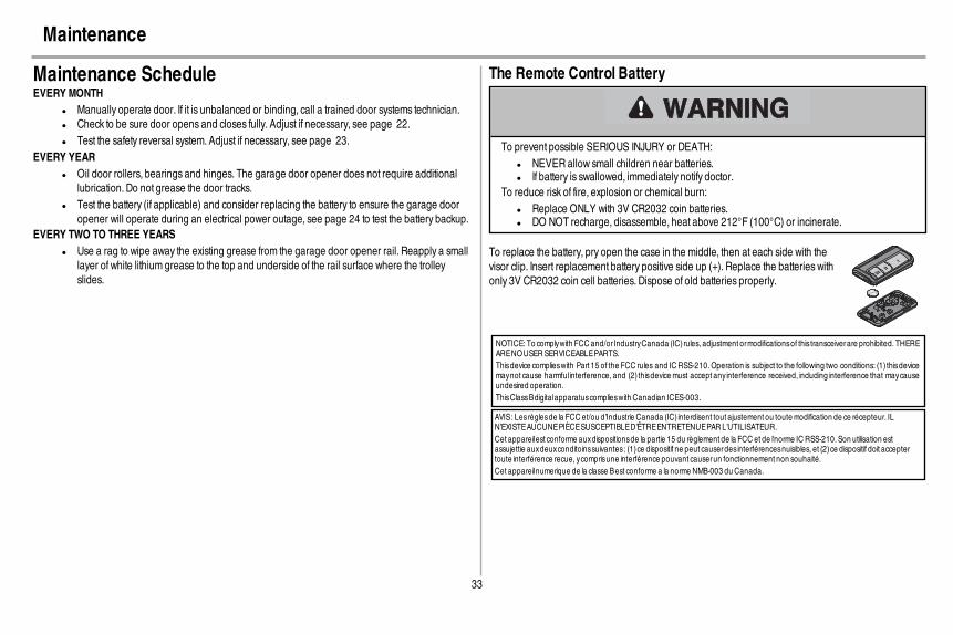
The Remote Control Battery
To prevent possible SERIOUS INJURY or DEATH:l NEVER allow small children near batteries.l If battery is swallowed, immediately notify doctor.
To reduce risk of fire, explosion or chemical burn:l Replace ONLY with 3V CR2032 coin batteries.l DO NOT recharge, disassemble, heat above 212°F (100°C) or incinerate.
To replace the battery, pry open the case in the middle, then at each side with thevisor clip. Insert replacement battery positive side up (+). Replace the batteries withonly 3V CR2032 coin cell batteries. Dispose of old batteries properly.
NOTICE: To complywith FCC and/or IndustryCanada (IC) rules, adjustment ormodificationsof this transceiverare prohibited. THEREARENOUSERSERVICEABLEPARTS.Thisdevice complieswith Part 15 of the FCC rules and ICRSS-210. Operation is subject to the following two conditions: (1) thisdevicemaynot cause harmfulinterference, and (2) thisdevice must accept any interference received, including interference that maycauseundesired operation.ThisClassBdigitalapparatuscomplieswith Canadian ICES-003.
AVIS: Lesrèglesde la FCC et/ou d’Industrie Canada (IC) interdisent tout ajustement ou toute modification de ce récepteur. ILN’EXISTEAUCUNEPIÈCESUSCEPTIBLED’ÊTREENTRETENUEPAR L’UTILISATEUR.Cet appareilest conforme auxdispositionsde la partie 15 du règlement de la FCC et de l'norme IC RSS-210. Son utilisation estassujettie auxdeuxconditoinssuivantes: (1)ce dispositif ne peut causerdesinterférencesnuisibles, et (2)ce dispositif doit acceptertoute interférence recue, ycomprisune interférence pouvant causerun fonctionnement non souhaité.Cet appareilnumerique de la classe Best conforme a la norme NMB-003 du Canada.

34
Your garage door opener is programmed with self-diagnostic capabilities. The UP and DOWNarrows on the garage door opener flash the diagnostic codes.
DIAGNOSTICCODE SYMPTOM SOLUTION
Up ArrowFlash(es)
Down ArrowFlash(es)
1 1 The garage door opener will not close and the lightbulbs flash.
Safety sensors are not installed, connected or wiresmay be cut. Inspect sensor wires for adisconnected or cut wire.
1 2 The garage door opener will not close and the lightbulbs flash.
There is a short or reversed wire for the safety sensors. Inspect safety sensor wire at all staple pointsand connection points and replace wire or correct as needed.
1 3 The door control will not function. The wires for the door control are shorted or the door control is faulty. Inspect safety sensor wire at allstaple points and connection points and replace wire or correct as needed.
1 4 The garage door opener will not close and the lightbulbs flash.
Safety sensors are misaligned or were momentarily obstructed. Realign both sensors to ensure bothLEDs are steady and not flickering.Make sure nothing is hanging or mounted on the door that wouldinterrupt the sensors path while closing.
1 5 Door moves 6-8" stops or reverses. Manually open and close the door. Check for binding or obstructions, such as a broken spring ordoor lock, correct as needed. Checkwiring connections at travel module and at the logic board.Replace travel module if necessary.
No movement, only a single click. Manually open and close the door. Check for binding or obstructions, such as a broken spring ordoor lock, correct as needed. Replace logic board if necessary.
Opener hums for 1-2 seconds no movement. Manually open and close the door. Check for binding or obstructions, such as a broken spring ordoor lock, correct as needed. Replace motor if necessary.
1 6 Door coast after it has come to a complete stop. Program travel to coasting position or have door balanced by a trained technician.
2 1-5 No movement or sound. Replace logic board.
3 2 Unable to set the travel or retain position. Check travel module for proper assembly, replace if necessary.
3 3 The battery status LED is constantly flashing green. Battery backup charging circuit error, replace logic board.
Troubleshooting

35
DIAGNOSTICCODE SYMPTOM SOLUTION
Up ArrowFlash(es)
Down ArrowFlash(es)
4 1-4 Door ismoving stops and or reverses. Manually open and close the door. Check for binding or obstructions, such as a broken spring ordoor lock, correct as needed. If the door is binding or sticking contact a trained door systemstechnician. If door is not binding or sticking attempt to reprogram travel (refer to page 22).
4 5 Opener runs approximately 6-8", stops and reverses. Communication error to travel module. Check travel module connections, replace module ifnecessary.
4 6 The garage door opener will not close and the lightbulbs flash.
Safety sensors are misaligned or were momentarily obstructed. Realign both sensors to ensure bothLEDs are steady and not flickering.Make sure nothing is hanging or mounted on the door that wouldinterrupt the sensor's path while closing.
The garage door opener can beep for several reasons:l (If applicable) Operating on battery power or the 12 Vdc battery needs to be
replaced, see page 25.l Garage door opener has been activated through a device or feature such as
Timer-to-Close, garage door monitor or LiftMaster Internet Gateway, see page 27.
My remote control will not activate the garage door:l Verify the lock feature is not activated on the door control.l Reprogram the remote control.l If the remote control will still not activate the door check the diagnostic codes to
ensure the garage door opener is working properly.My doorwill not close and the light bulbs blink onmy motor unit:
The safety reversing sensor must be connected and aligned correctly before the garagedoor opener will move in the down direction.
l Verify the safety sensors are properly installed, aligned and free of anyobstructions.
My garage door opener light(s) will not turn off when the door is open:The garage door opener is equipped with a feature that turns the light on when the safety reversing sensorshave been obstructed or when the motion sensor on the door control detectsmovement in the garage. Thesefeatures can be disabled using the door control, see page 29.My neighbor’s remote control opens my garage door:Erase the memory from your garage door opener and reprogram the remote control(s).The LEDs on the door control blink:If you have a Smart Control Panel installed and the TTC is set to a custom time, press the ON button on thePremiumMotion-Detecting Control Panel to set the time properly.My vehicle's Homelink® is not programming tomy garage door opener:Depending on the make,model, and year of your vehicle an external adapter may be required. Visitwww.homelink.com for additional information.
Troubleshooting
36
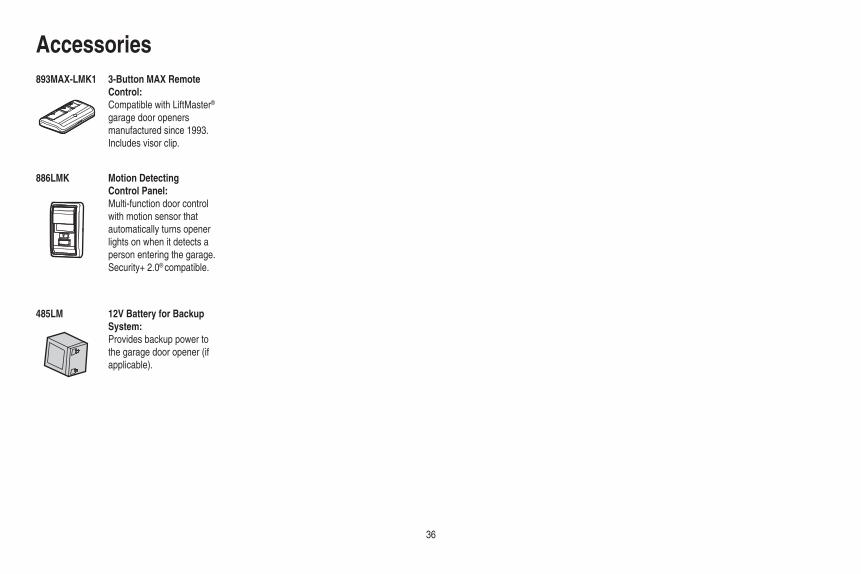
Accessories893MAX-LMK1
886LMK
3-Button MAX Remote Control:Compatible with LiftMaster® garage door openers manufactured since 1993. Includes visor clip.
Motion Detecting Control Panel:Multi-function door control with motion sensor that automatically turns opener lights on when it detects a person entering the garage. Security+ 2.0® compatible.
485LM 12V Battery for Backup System:Provides backup power to the garage door opener (if applicable).
37
Warranty
MERIK ONE YEAR LIMITED WARRANTYLIFETIME MOTOR LIMITED WARRANTY
ONE YEAR LIMITED WARRANTY FOR THE BATTERY BACKUP SYSTEM*
Merik (“Seller”) warrants to the fi rst retail purchaser of this product, for the residence in which this product is originally installed, that it is free from defects in materials and/or workmanship for a period of one year from the date of purchase, except that the motor is warranted to be free from defects in materials and/or workmanship for the lifetime of the product while you own your residence, and the Battery Backup System* is warranted to be free from defects in materials and/or workmanship for a period of one year from the date of purchase. The proper operation of this product is dependent on your compliance with the instructions regarding installation, operation, and maintenance and testing. Failure to comply strictly with those instructions will void this limited warranty in its entirety.
If, during the limited warranty period, this product appears to contain a defect covered by this limited warranty, call our service number or the servicing distributor in your area, before dismantling this product. You will be advised of disassembly and shipping instructions when you call. Then send the product or component, pre-paid and insured, as directed to our service center for warranty repair. Please include a brief description of the problem and a dated proof-of-purchase receipt with any product returned for warranty repair. Products returned to Seller for warranty repair, which upon receipt by Seller are confi rmed to be defective and covered by this limited warranty, will be repaired or replaced (at Seller’s sole option) at no cost to you and returned pre-paid. Defective parts will be repaired or replaced with new or factory-rebuilt parts at Seller’s sole option. [You are responsible for any costs incurred in removing and/or reinstalling the product or any component .]
ALL IMPLIED WARRANTIES FOR THE PRODUCT, INCLUDING BUT NOT LIMITED TO ANY IMPLIED WARRANTIES OF MERCHANTABILITY AND FITNESS FOR A PARTICULAR PURPOSE, ARE LIMITED IN DURATION TO THE APPLICABLE LIMITED WARRANTY PERIOD SET FORTH ABOVE FOR THE RELATED COMPONENT(S), AND NO IMPLIED WARRANTIES WILL EXIST OR APPLY AFTER SUCH PERIOD. Some States do not allow limitations on how long an implied warranty lasts, so the above limitation may not apply to you. THIS LIMITED WARRANTY DOES NOT COVER NON-DEFECT DAMAGE, DAMAGE CAUSED BY IMPROPER INSTALLATION, OPERATION OR CARE (INCLUDING, BUT NOT LIMITED TO ABUSE, MISUSE, FAILURE TO PROVIDE REASONABLE AND NECESSARY MAINTENANCE, UNAUTHORIZED REPAIRS OR ANY ALTERATIONS TO THIS PRODUCT), LABOR CHARGES FOR REINSTALLING A REPAIRED OR REPLACED UNIT, REPLACEMENT OF CONSUMABLE ITEMS (E.G., BATTERIES IN REMOTE CONTROL TRANSMITTERS AND LIGHT BULBS), OR UNITS INSTALLED FOR NON-RESIDENTIAL USE. THIS LIMITED WARRANTY DOES NOT COVER ANY PROBLEMS WITH, OR RELATING TO, THE GARAGE DOOR OR GARAGE DOOR HARDWARE, INCLUDING BUT NOT LIMITED TO THE DOOR SPRINGS, DOOR ROLLERS, DOOR ALIGNMENT OR HINGES. THIS LIMITED WARRANTY ALSO DOES NOT COVER ANY PROBLEMS CAUSED BY INTERFERENCE. UNDER NO CIRCUMSTANCES SHALL SELLER BE LIABLE FOR CONSEQUENTIAL, INCIDENTAL OR SPECIAL DAMAGES ARISING IN CONNECTION WITH USE, OR INABILITY TO USE, THIS PRODUCT. IN NO EVENT SHALL SELLER’S LIABILITY FOR BREACH OF WARRANTY, BREACH OF CONTRACT, NEGLIGENCE OR STRICT LIABILITY EXCEED THE COST OF THE PRODUCT COVERED HEREBY. NO PERSON IS AUTHORIZED TO ASSUME FOR US ANY OTHER LIABILITY IN CONNECTION WITH THE SALE OF THIS PRODUCT.
Some states do not allow the exclusion or limitation of consequential, incidental or special damages, so the above limitation or exclusion may not apply to you. This limited warranty gives you specifi c legal rights, and you may also have other rights, which vary from state to state.
* If applicable.
38
Repair PartsRail Assembly Parts
Installation Parts
1
3
4
5
6
2
NOTICE
UPCEILING MOUNT ONLY
123
4
5
6
7
8
9
10
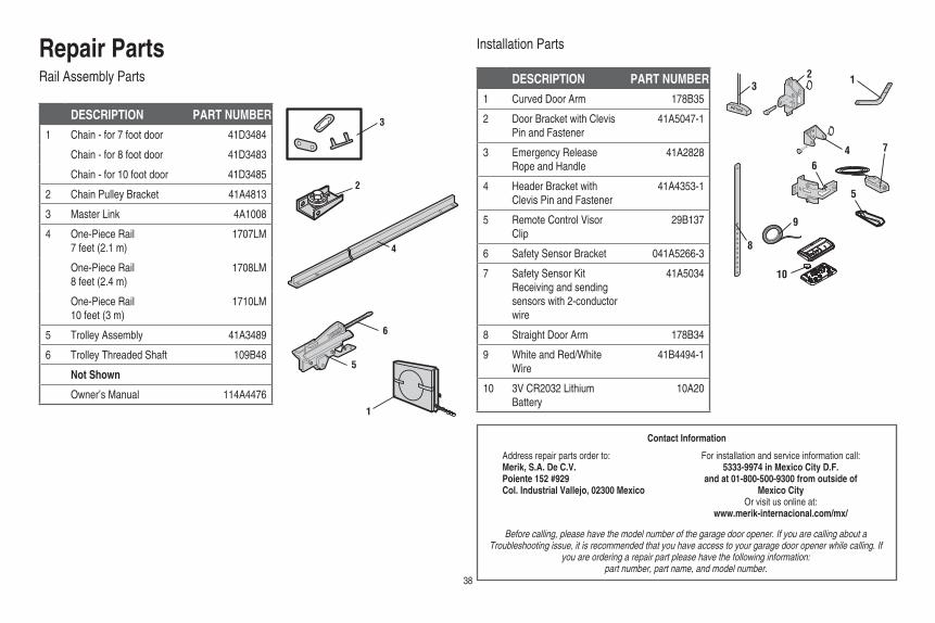
DESCRIPTION PART NUMBER
1 Chain - for 7 foot door 41D3484
Chain - for 8 foot door 41D3483
Chain - for 10 foot door 41D3485
2 Chain Pulley Bracket 41A4813
3 Master Link 4A1008
4 One-Piece Rail 7 feet (2.1 m)
1707LM
One-Piece Rail 8 feet (2.4 m)
1708LM
One-Piece Rail 10 feet (3 m)
1710LM
5 Trolley Assembly 41A3489
6 Trolley Threaded Shaft 109B48
Not Shown
Owner’s Manual 114A4476
DESCRIPTION PART NUMBER
1 Curved Door Arm 178B35
2 Door Bracket with Clevis Pin and Fastener
41A5047-1
3 Emergency Release Rope and Handle
41A2828
4 Header Bracket with Clevis Pin and Fastener
41A4353-1
5 Remote Control Visor Clip
29B137
6 Safety Sensor Bracket 041A5266-3
7 Safety Sensor KitReceiving and sending sensors with 2-conductor wire
41A5034
8 Straight Door Arm 178B34
9 White and Red/White Wire
41B4494-1
10 3V CR2032 Lithium Battery
10A20
Contact Information
Before calling, please have the model number of the garage door opener. If you are calling about a Troubleshooting issue, it is recommended that you have access to your garage door opener while calling. If
you are ordering a repair part please have the following information:part number, part name, and model number.
Address repair parts order to:Merik, S.A. De C.V.Poiente 152 #929Col. Industrial Vallejo, 02300 Mexico
For installation and service information call:5333-9974 in Mexico City D.F.
and at 01-800-500-9300 from outside of Mexico City
Or visit us online at:www.merik-internacional.com/mx/

11
12b12a
4
10
1
95
3
6
2
78
4 3
Repair PartsGarage Door Opener Parts
DESCRIPTION PART NUMBER1 Sprocket and Sprocket Cover 41B5348-2
2 End Panel with battery cover and light socket 41D217
3 Light Lens 41A7562
4 Light Socket 41C279
5 Transformer 41A7635
6 Cover 41A7619-8
7 Motor and Travel Module 41D1739-1
8 Travel Module 41A7114-7
9 End Panel with light socket 41D216
10 Receiver Logic Board 45DCT
11 Line Cord
Models manufactured before October 2012 41B135-1
Models manufactured after October 2012 41B4245
12a Filter Board with Screws (modelsmanufactured before October 2012)
41B7611
12b Terminal Block (models manufacturedafter October 2012)
41A3150
Not Shown
Wire Harness with Screws (models manufactured before October 2012)
41B7418
Wire Harness with Screws (models manufactured after October 2012)
41B7610-1
© 2015, The Chamberlain Group, Inc.114A4476E All Rights Reserved

CONTENIDOPreparación . . . . . . . . . . . . . . .1-2Ensamblado . . . . . . . . . . . . . . .3-4Instalación . . . . . . . . . . . . . . . 5-12Instalar el control de la puerta 13-14Instalar el Protector System®. . 15-18Energía. . . . . . . . . . . . . . . . . 19-20Ajustes . . . . . . . . . . . . . . . . . 21-23Batería de repuesto* . . . . . . . 24-25Operación . . . . . . . . . . . . . . . . . 26Funciones . . . . . . . . . . . . . . . . . 27Control de la puerta . . . . . . . . 28-29Control remoto. . . . . . . . . . . . . . 30Para borrar la memoria. . . . . . . . 31Para abrir la puerta manualmente 32Mantenimiento . . . . . . . . . . . . . 33Resolución de problemas . . . . 34-35Accesorios . . . . . . . . . . . . . . . . 36Garantía . . . . . . . . . . . . . . . . . . 37Piezas de repuesto. . . . . . . . . 38-39
*Si corresponde
Abre-puertas de garaje de cadena
■ ¡Lea atentamente el contenido de este manual y las instrucciones de seguridad en él incluidas!
■ Al terminar la instalación, deje el manual a mano cerca de la puerta del garaje.
■ La puerta NO SE CERRARÁ si el Protector System® no está conectado y debidamente alineado.
■ Como medida de seguridad, es conveniente efectuar inspecciones periódicas del mecanismo de apertura.
■ La etiqueta con el número de modelo se encuentra en el panel frontal del abre-puertas.
■ Esté abre-puerta del garaje es compatibles con accesorios de MyQ® y Security+ 2.0® SOLAMENTE.
■ NO uso el característica Temporizador para cierra se el abre-puertas del garaje es instalado en un puerta de un sola pieza. El característica temporizador para cierra es SOLÓ para uso con puertas seccionales.
Numero de seria:
Fecha de compra:
Escribir la información que siguien por referencia en la futura:
Modelo 7511LMKSÓLO PARA USO RESIDENCIAL
.
www.merik-internacional.com/mx/
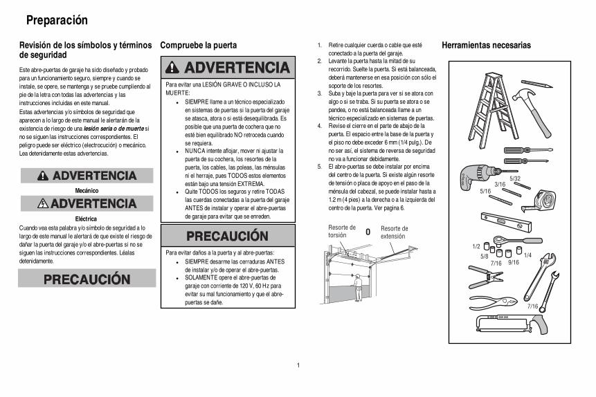
1
Revisión de los símbolos y términosde seguridad
Este abre-puertas de garaje ha sido diseñado y probadopara un funcionamiento seguro, siempre y cuando seinstale, se opere, se mantenga y se pruebe cumpliendo alpie de la letra con todas las advertencias y lasinstrucciones incluidas en este manual.Estas advertencias y/o símbolos de seguridad queaparecen a lo largo de este manual le alertarán de laexistencia de riesgo de una lesión seria o de muerte sino se siguen las instrucciones correspondientes. Elpeligro puede ser eléctrico (electrocución) o mecánico.Lea detenidamente estas advertencias.
Mecánico
EléctricaCuando vea esta palabra y/o símbolo de seguridad a lolargo de este manual le alertará de que existe el riesgo dedañar la puerta del garaje y/o el abre-puertas si no sesiguen las instrucciones correspondientes. Léalasdetenidamente.
Compruebe la puerta
Para evitar una LESIÓN GRAVE O INCLUSO LAMUERTE:
l SIEMPRE llame a un técnico especializadoen sistemas de puertas si la puerta del garajese atasca, atora o si está desequilibrada. Esposible que una puerta de cochera que noesté bien equilibrado NO retroceda cuandose requiera.
l NUNCA intente aflojar, mover ni ajustar lapuerta de su cochera, los resortes de lapuerta, los cables, las poleas, las ménsulasni el herraje, pues TODOS estos elementosestán bajo una tensión EXTREMA.
l Quite TODOS los seguros y retire TODASlas cuerdas conectadas a la puerta del garajeANTES de instalar y operar el abre-puertasde garaje para evitar que se enreden.
Para evitar daños a la puerta y al abre-puertas:l SIEMPRE desarme las cerraduras ANTES
de instalar y/o de operar el abre-puertas.l SOLAMENTE opere el abre-puertas de
garaje con corriente de 120 V, 60 Hz paraevitar su mal funcionamiento y que el abre-puertas se dañe.
1. Retire cualquier cuerda o cable que estéconectado a la puerta del garaje.
2. Levante la puerta hasta la mitad de surecorrido. Suelte la puerta. Si está balanceada,deberá mantenerse en esa posición con sólo elsoporte de los resortes.
3. Suba y baje la puerta para ver si se atora conalgo o si se traba. Si su puerta se atora o sepandea, o no está balanceada llame a untécnico especializado en sistemas de puertas.
4. Revise el cierre en el parte de abajo de lapuerta. El espacio entre la base de la puerta yel piso no debe exceder 6 mm (1/4 pulg.). Deno ser así, el sistema de reversa de seguridadno va a funcionar debidamente.
5. El abre-puertas se debe instalar por encimadel centro de la puerta. Si existe algún resortede tensión o placa de apoyo en el paso de laménsula del cabezal, se puede instalar hasta a1.2 m (4 pies) a la derecha o a la izquierda delcentro de la puerta. Ver pagina 6.
Resorte de
torsión
Resorte de
extensiónO
Herramientas necesarias
21
3/16
7/16
1/2
5/32
5/16
5/8
9/16
1/4
7/16
Preparación
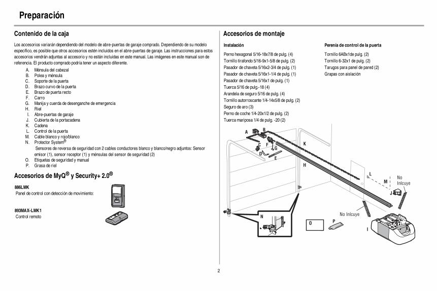
2
Contenido de la caja
Los accesorios variarán dependiendo del modelo de abre-puertas de garaje comprado. Dependiendo de su modeloespecífico, es posible que otros accesorios estén incluidos en el abre-puertas de garaje. Las instrucciones para estosaccesorios vendrán adjuntas al accesorio y no están incluidas en este manual. Las imágenes en este manual son dereferencia. El producto comprado podría tener un aspecto diferente.
A. Ménsula del cabezalB. Polea y ménsulaC. Soporte de la puertaD. Brazo curvo de la puertaE. Brazo de puerta rectoF. CarroG. Manija y cuerda de desenganche de emergenciaH. RielI. Abre-puertas de garajeJ. Cubierta de la portacadenaK. CadenaL. Control de la puertaM. Cable blanco y rojo/blancoN. Protector System®
Sensores de reversa de seguridad con 2 cables conductores blanco y blanco/negro adjuntos: Sensoremisor (1), sensor receptor (1) y ménsulas del sensor de seguridad (2)
O. Etiquetas de seguridad y manualP. Grasa de riel
Accesorios de MyQ® y Security+ 2.0®
886LMKPanel de control con detección de movimiento:
893MAX-LMK1Control remoto
Accesorios de montaje
Instalación Perenía de control de la puerta
Perno hexagonal 5/16-18x7/8 de pulg. (4) Tornillo 6ABx1de pulg. (2)Tornillo tirafondo 5/16-9x1-5/8 de pulg. (2) Tornillo 6-32x1 de pulg. (2)Pasador de chaveta 5/16x2-3/4 de pulg. (1) Tarugos para panel de pared (2)Pasador de chaveta 5/16x1-1/4 de pulg. (1) Grapas con aislaciónPasador de chaveta 5/16x1 de pulg. (1)Tuerca 5/16 de pulg.-18 (4)Arandela de seguro 5/16 de pulg. (4)Tornillo autorroscante 1/4-14x5/8 de pulg. (2)Seguro de aro (3)Perno de coche 1/4-20x1/2 de pulg. (2)Tuerca mariposa 1/4 de pulg. -20 (2)
AB
C
J
N
I
O
DE
F
H
GK
L
M
No Inlcuye
No
Inlcuye
P
Preparación

3
Ensamble
1 Coloque el riel al abre-puertas de garaje
Para evitar posibles LESIONES GRAVES en los dedos causadas por las partes móviles del abre-puertas degaraje:
l SIEMPRE tenga las manos lejos de la rueda dentada mientras el abridor esté en funcionamiento.l Ponga bien la cubierta de la rueda dentada ANTES de hacer funcionar el abridor.
Para evitar daños GRAVES en el abre-puertas, utilice SOLAMENTE los pernos/sujetadores que vienen montadosen la parte superior del abridor.
NOTA: Use SÓLO los pernos que se quitaron del abre-puertas de garaje. Colocar el abre-puertas de garaje materialde empaque para proteger la cubierta.
1. Quite los dos pernos de la parte superior del abre-puertas de garaje.2. Alinee el riel y la espuma de estireno sobre la rueda dentada. Corte la cinta al riel, cadena y espuma.3. Fije el riel con los pernos previamente colopcados.4. Posición la correa al portacadena del abre-puertas de garaje.5. Instale la cubierta de la rueda dentada oprimiendo los lados e insertando las lengüetas en las ranuras en el
abre-puertas de garaje.
Perno con arandela
5/16-18x1/2 de pulg.
Perno con arandela
5/16-18x1/2 de pulg.
(Monte en el abre-puertas de garaje)
PERNÌA
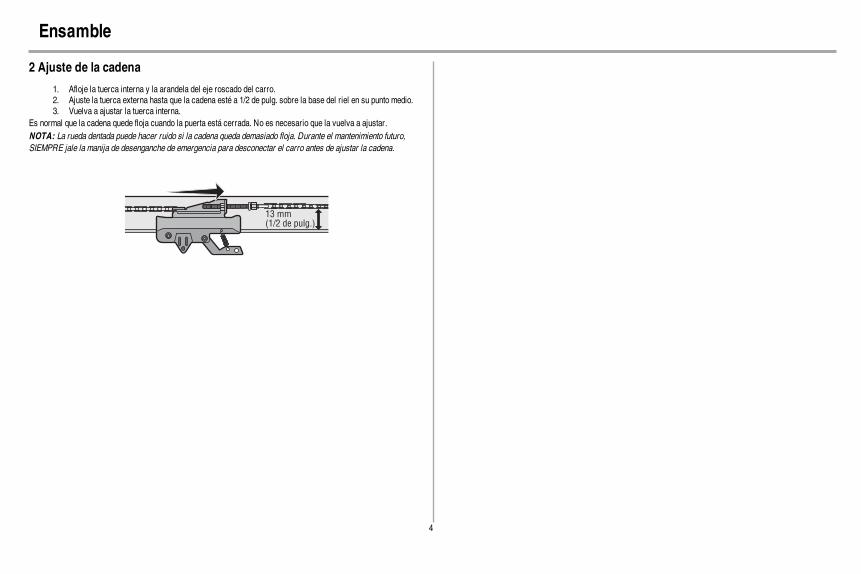
4
Ensamble
2 Ajuste de la cadena
1. Afloje la tuerca interna y la arandela del eje roscado del carro.2. Ajuste la tuerca externa hasta que la cadena esté a 1/2 de pulg. sobre la base del riel en su punto medio.3. Vuelva a ajustar la tuerca interna.
Es normal que la cadena quede floja cuando la puerta está cerrada. No es necesario que la vuelva a ajustar.NOTA: La rueda dentada puede hacer ruido si la cadena queda demasiado floja. Durante el mantenimiento futuro,SIEMPRE jale la manija de desenganche de emergencia para desconectar el carro antes de ajustar la cadena.
13 mm(1/2 de pulg.)
5
Instalación
INSTRUCCIONES IMPORTANTES DE INSTALACIÓN
Para reducir el riesgo de LESIONES GRAVES o la MUERTE:1. LEA Y RESPETE TODAS LAS ADVERTENCIAS Y LAS INSTRUCCIONES DE INSTALACIÓN.2. Instale el abre-puertas de garaje SOLAMENTE en puertas de garaje que estén bien equilibrados y
lubricados. Es posible que una puerta que no esté bien equilibrada NO funcione en reversa cuando seanecesario, lo cual puede ocasionar LESIONES GRAVES o la MUERTE.
3. TODAS las reparaciones de los cables, resortes y otras partes DEBEN ser realizadas por un técnicoespecializado en sistemas de puertas, ANTES de instalar el abridor.
4. Desarme TODOS los seguros y retire TODAS las cuerdas conectadas a la puerta de el cocheraANTES de instalar el abridor para evitar que estas se enreden.
5. Instale el abre-puertas de garaje a una distancia de 2.13 m (7 pies) del piso.6. Monte la manija de desenganche de emergencia de modo que esté al alcance, pero con una altura
mínima de 1.83 m (6 pies) del piso para evitar el contacto con los vehículos y que se suelteaccidentalmente.
7. No conecte NUNCA el abre-puertas del garaje a una fuente de energía eléctrica hasta que se leindique.
8. NUNCA lleve puestos relojes, anillos o prendas sueltas durante la instalación o funcionamiento delabre-puertas, pues podrían atorarse en la puerta del garaje o en los mecanismos del abre-puertas.
9. Instale el control de la puerta de cochera montado en pared:l de manera que quede a la vista desde la puerta del garaje.l fuera del alcance de los niños y a una altura mínima de 1.5 m (5 pies).l lejos de TODAS las partes móviles de la puerta.
10. Coloque la etiqueta de advertencia del riesgo de quedar atrapado en la pared cerca del control de lapuerta del garaje.
11. Coloque la etiqueta de prueba de reversa de seguridad/desenganche de emergencia a plena vista en laparte interior de la puerta del garaje.
12. Pruebe el sistema de reversa de seguridad al terminar la instalación. La puerta del garaje DEBEretroceder al entrar en contacto con un objeto de 3.8 cm (1-1/2 de pulg) de altura (o de 5 x 10 cm [2 x 4pulg.] acostado en el piso).
13. Para evitar lesiones personales GRAVES o la MUERTE por electrocución, desconectarTOTALMENTE la energía eléctrica y de la batería ANTES de realizar CUALQUIER tipo demantenimiento.
14. NO activar el temporizador de cierre en puertas de garaje de una sola pieza o puertas batientes. Usaresta función ÚNICAMENTE con puertas seccionales.
NOTA: Si instale el abre-puertas de garaje en un puerta de una pieza, vea www.merik.com.mx para instrucciones de instalación.

6
Instalación
1 Determinar la localización de soporte de cabecera
Para evitar posibles LESIONES GRAVES o la MUERTE:l La ménsula del cabezal DEBE quedar RÍGIDAMENTE sujeta al soporte estructural en la pared delantera
o en el cielo raso, de no ser así es posible que la puerta del garaje NO retroceda cuando se requiera. NOinstale el soporte de travesaño en muros divisorios.
l Se DEBEN utilizar anclajes de concreto si se monta el soporte de travesaño o 2x4 en la mampostería.l NUNCA trate de aflojar, mover, ni ajustar la puerta del garaje, los resortes, los cables, las poleas, las
ménsulas ni la pernería, pues TODAS estas piezas están bajo una tensión EXTREMA.l SIEMPRE llame a un técnico especializado en sistemas de puertas si la puerta del garaje se atasca, atora
o si está desequilibrada. Una puerta de garaje que no esté equilibrada puede NO retroceder cuando serequiera.
l NO activar el temporizador de cierre en puertas de garaje de una sola pieza o puertas batientes. Usaresta función ÚNICAMENTE con puertas seccionales.
NOTA: Si instale el abre-puertas de garaje en un puerta de una pieza, vea www.merik.com.mx para instrucciones deinstalación.
Cierre la puerta y marque la línea central vertical del interior de la puerta del cochera.Extender la línea de centro hasta la pared del cabezal que se ubica sobre la puerta. Es posible instalar la ménsula delcabezal hasta a una distancia de 1.22 m (4 pies) a cada lado del centro de la puerta, pero solamente si un resorte detorsión o una placa central de apoyo se encuentra en el recorrido. También se puede instalar la ménsula en el cieloraso cuando el espacio es reducido. (Asimismo, se puede instalar en forma invertida sobre la pared si fuese necesario.Esto le dará aproximadamente 1 cm [1/2 pulg.] de espacio). Si necesita instalar la ménsula del cabezal sobre un pedazode madera de 5 x 10 cm (2 x 4 pulg.) (ya sea en la pared o en el cielo raso), utilice tornillos de cabeza cuadrada o pijas(no se incluyen) para sujetar bien el pedazo de madera a los soportes estructurales.Abra la puerta hasta el punto más alto de su recorrido. Marque una línea horizontal que intersecte la pared delantera a5 cm (2 pulg.) del punto más alto del recorrido. A esta altura, el extremo superior de la puerta tendrá suficiente espaciopara su recorrido.NOTA: Si la distancia total supera la altura disponible de el garaje, use la altura máxima posible o consulte la página 7en el cielo.
Pared frontal
Cielo raso sin
terminación
Linea vertical del
centro de la puerta 3.8 cm
(2x4 pulg.)Soportes de
la estructurales
Nivel
(opcional)
MONTAJE
OPCIONAL DE
MÉNSULA DE
CABEZAL
EL TECHO
Puerta seccional con guía curva
Pared frontal
Guía
5 cm (2 pulg.)
Punto más
alto de recorrido
Puerta

7
Instalación
2 Instalación de la ménsula del cabezal
La ménsula del cabezal se puede sujetar a la pared sobre la puerta del garaje o en el cielo raso. Siga las instruccionesque sean las más adecuadas para las necesidades de su garaje. No instale la ménsula del cabezal en un muro falso. Sila instalación es en mampostería, asegúrese de utilizar sujetadores de cemento (no se incluyen).
PERENÍA
Tornillo tirafondo
5/16 de pulg. -9x1-5/8 de pulg.
OPCIÓN A INSTALACIÓN DE LA MÉNSULA DEL CABEZAL EN LA PARED
1. Coloque la ménsula sobre la línea central vertical con el borde inferior sobre la línea horizontal como semuestra en la ilustración (con la flecha de la ménsula apuntando hacia el cielo raso).
2. Marque los orificios de la ménsula que van en línea vertical (no use los orificios designados para lainstalación en el cielo raso). Taladre los orificios con una broca de 3/16 de pulg. y sujete la ménsulafirmemente al soporte de la estructura con la pernería que se incluye.
Orificios para la
instalación de pared
Orificios opcionales
para la instalación
Línea vertical
del centro de
la puerta
(Pared frontal)
Soporte estructural
de 3.8 cm
(2x4 pulg.)
Resorte de
puerta
(Puerta del
garaje)Punto más alto
de recorrido de
la puerta
Línea
horizontal
Tornillo tirafondo
5/16 de pulg.-
9x1-5/8 de pulg.
Ménsula
del
cabezal
OPCIÓN B INSTALACIÓN DE LA MÉNSULA DEL CABEZAL EN EL CIELO RASO
1. Continúe marcando la línea central vertical sobre el cielo raso como se muestra en la ilustración.2. Coloque la ménsula al centro de la línea a no más de 15 cm (6 pulg.) de la pared. Asegúrase de que la
flecha de la ménsula apunte hacia la pared. La ménsula puede ser instalada pegada al cielo raso cuando elespacio es muy reducido.
3. Marque dónde taladrará los orificios laterales. Taladre los orificios con una broca de 3/16 de pulg. y sujetela ménsula firmemente al soporte de la estructura con los torillo autorroscante.
(Pared Frontal)
Orificios para la instalación
de pared
(Cielo Raso)
Línea vertical
del centro de
la puerta
Ménsula del
cabezal
15 cm (6 pulg.)
máximo
Resorte
de puerta
(Puerta del
garaje)
Tornillo tirafondo
5/16 de pulg.-
9x1-5/8 de pulg.
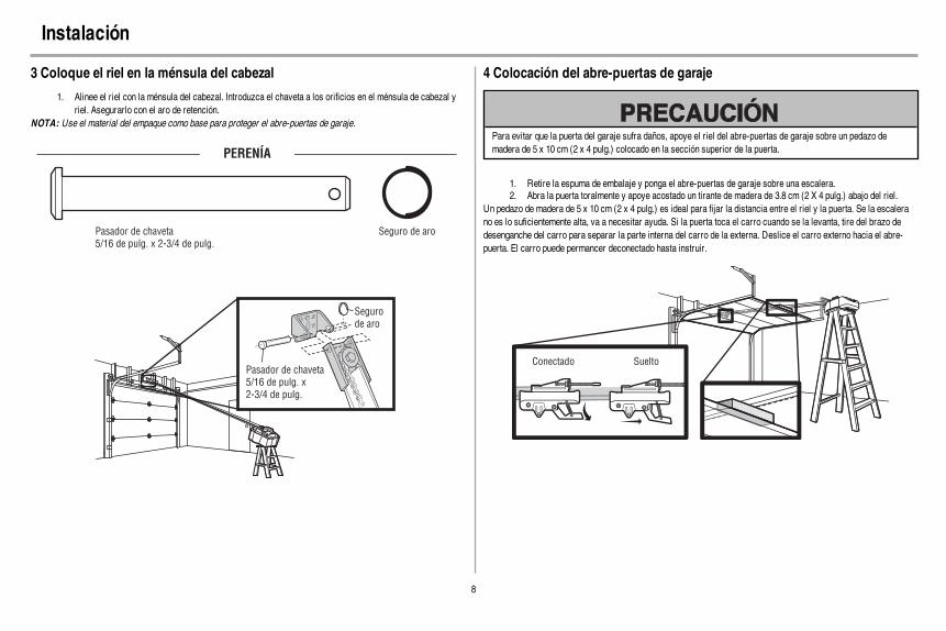
8
Instalación
3 Coloque el riel en la ménsula del cabezal
1. Alinee el riel con la ménsula del cabezal. Introduzca el chaveta a los orificios en el ménsula de cabezal yriel. Asegurarlo con el aro de retención.
NOTA: Use el material del empaque como base para proteger el abre-puertas de garaje.
PERENÍA
Pasador de chaveta
5/16 de pulg. x 2-3/4 de pulg.
Seguro de aro
Seguro
de aro
Pasador de chaveta
5/16 de pulg. x
2-3/4 de pulg.
4 Colocación del abre-puertas de garaje
Para evitar que la puerta del garaje sufra daños, apoye el riel del abre-puertas de garaje sobre un pedazo demadera de 5 x 10 cm (2 x 4 pulg.) colocado en la sección superior de la puerta.
1. Retire la espuma de embalaje y ponga el abre-puertas de garaje sobre una escalera.2. Abra la puerta toralmente y apoye acostado un tirante de madera de 3.8 cm (2 X 4 pulg.) abajo del riel.
Un pedazo de madera de 5 x 10 cm (2 x 4 pulg.) es ideal para fijar la distancia entre el riel y la puerta. Se la escalerano es lo suficientemente alta, va a necesitar ayuda. Si la puerta toca el carro cuando se la levanta, tire del brazo dedesenganche del carro para separar la parte interna del carro de la externa. Deslice el carro externo hacia el abre-puerta. El carro puede permancer deconectado hasta instruir.
Conectado Suelto

9
Instalación
5 Cuelgue el abre-puertas
Para evitar la posibilidad de una LESIÓN GRAVE si se cae el abre-puertas de garaje, sujételo FIRMEMENTE alos soportes estructurales del garaje. Se DEBEN usar anclajes de hormigón si se instalan ménsulas en lamampostería.
El colgante de su abre-puertas del garaje variará dependiendo de su garaje. Se muestran dos instalaciónesrepresentativas. Quizá su instalación sea diferente. Las soportes colgantes se deben colocar en ángulo (Figura 1) paralograr un soporte rígido. En los techos acabados (Figura 2), colocar un soporte metá lico robusto sobre los soportesestructurales antes de instalar el abre-puertas. Este soporte y los accesorios no se incluyen con el abre-puertas.
1. Mida la distancia entre cada lado de la unidad del motor y el soporte de la estructura.2. Corte las dos partes de los soportes colgantes a la medida adecuada.3. Taladre los orificios de 3/16 de pulg. en los soportes de la estructura.4. Sujete un extremo de cada soporte colgante al soporte principal con tornillos tirafondo de 5/16 -18x1-7/8
pulgadas (no incluye).5. Sujete el abre-puertas a los soportes colgantes con pernos hexagonales de 5/16 -18x7/8 pulgadas, y sus
tuercas y roldanas corespondientes.6. Verifique que el abre-puertas esté centrado sobre la puerta (o alineado con la ménsula del cabezal, si la
ménsula no está centrada sobre la puerta).7. Quite el tirante de madera de 3.8 mm (2x4 pulg.). Opere la puerta manualmente. Si la puerta golpea el riel,
suba la ménsula del cabezal.
NOTA: NO conecte todavía la alimentación eléctrica al abre-puertas.
FIGURA 1 FIGURA 2
(No incluida)
Tornillo tirafondo
5/16 de pulg. - 18x1-7/8 de pulg.
Mida la
distancia
Perno de 5/16-18x7/8 de pulg., Arandela de
presión de 5/16 de pulg., Tuerca de 5/16-18 de pulg.
FIGURA 3
No incluida
Cielo rasoCielo raso sin acabado
Perno de 5/16-18x7/8 de pulg. Tuerca de
5/16-18 de pulg.
Arandela de presión de
5/16 de pulg.
PERENÍA

10
Instalación
6 Instalación de las bombillas
Para evitar un posible SOBRECALENTAMIENTO del portabombillas:l Use ÚNICAMENTE bombillas incandescentes A19 (100 voltios máximo) o fluorescentes compactas
(26 voltios máximo).l NO utilice bombillas de más de 100 W.l NO usar lámparas fluorescentes compactas de más de 26 W (equivalente a 100 W).l NO utilice bombillas de halógeno.l NO utilice bombillas de cuello corto ni de tipo especial.
1. Tirar al centro de la parte superior del lente y girar el lente abajo.2. Introduzca una bombilla A19 (100 vatios máximo) incandescente o fluorescente compacta (26 vatios,
equivalente a 100 vatios) en el receptáculo para la bombilla.NOTA: El uso de bombillas de cuello corto o especiales puede sobrecalentar el panel o el receptácula para labombilla. No use lámparas de DEL ya que pueden reducir el alcance o incluso el funcionamiento del control remoto.
3. Rote la lente suavemente hacia arriba para cerrar.
o o
7 Montaje de la manija y la cuerda de emergencia
Para evitar la posibilidad de una LESIÓN GRAVE O INCLUSO LA MUERTE si la puerta del garaje se cae:l De ser posible, use el desenganche de emergencia para soltar el carro SÓLO cuando la puerta del
cochera esté CERRADA. Si los resortes están débiles o rotos o si la puerta está desequilibrada, podríaabrirse y caer rápida y/o inesperadamente.
l NUNCA use la manija de emergencia a menos que la entrada a la cochera esté libre de obstrucciones yno haya ninguna persona presente.
l NUNCA use la manija para tirar de la puerta para abrirla o cerrarla. Si el nudo de la cuerda se suelta,usted podría caerse.
1. Inserte un extremo de la cuerda de desenganche de emergencia a través de la manija. Verifique la palabra“NOTICE” (aviso) sea legible. Asegúrela con un nudo por lo menos a 2.5 cm (1 pulgada) del extremo de lacuerda de desenganche de emergencia.
2. Inserte el otro extremo de la cuerda de desenganche de emergencia a través del orificio del brazo dedesenganche del carro. Instale la cuerda de emergencia donde pueda ser alcanzado, al menos a 6 pies(1.83 m) sobre el nivel piso, donde no esté en riesgo de entrar en contacto con vehículos y fílelo con unnudo.
NOTA: Si es necesario cortar la cuerda de desenganche de emergencia, queme el extremo cortado con un fósforo ocon un encendedor para evitar que el cordón se desate. Asegúrese de que la cuerda de desenganche de emergencia yla manija estén encima de la parte superior de los vehículos para que no se enreden.
Brazo de
liberación del
carro

11
Instalación
8 Instale la ménsula de la puerta
Para puertas de garaje de fibra de vidrio, acero fino o aluminio, es NECESARIO un refuerzo ANTES de instalarla ménsula de puerta. Consulte con el fabricante de la de la puerta del garaje o vendedor instalación para abridorrefuerzo instrucciones o juegos de refuerzo. Fracaso para reforzar la parte superior como se requiere según elfabricante de la puerta puede anular la garantía de la puerta.
Se necesita un refuerzo horizontal y otro vertical para puertas degaraje livianas (fibra de vidrio, aluminio, acero, puertas con panelde vidrio, etc.) (no suministradas). Si usa un tirante horizontal,éste debe de ser lo suficientemente largo para fijarse en dos o tressoportes verticales. Si usa un tirante vertical, éste debe de ser dela altura del panel superior. Póngase en contacto con el fabricanteo el distribuidor de instalación de la puerta del garaje para obtenerinstrucciones de refuerzo del abridor o un juego de refuerzo.
NOTA: Muchos de los juegos de refuerzo permiten la conexión directa de los pasadores de chaveta y del brazo de lapuerta. En este caso, no necesitará instalar la ménsula de la puerta. Continúe con el siguiente paso.
PUERTAS SECCIONALES
1. Coloque la ménsula de la puerta sobre la línea central vertical que había marcado previamente para lainstalación de la ménsula del cabezal. Asegúrese de que la leyenda "UP" (arriba) esté en la posicióncorrecta, como se indica en la parte interior de la ménsula.
2. El borde superior de la ménsula debe quedar a una distancia de 5 a 10 cm (2 a 4 pulgadas) por debajo delborde superior de la puerta, O directamente bajo un soporte transversal en la parte superior de la puerta.
3. Haga los agujeros y proceda con las siguientes instrucciones de instalación, según el tipo de puerta:Puertas metálicas o livianas con refuerzo vertical de hierro en ángulo entre el soporte del panel de la puerta yla ménsula de la puerta:
l Taladre los orificios de sujeción de 3/16 de pulg. Fije la ménsula de la puerta con dos tornillosautorroscantes. (Figura 1)
l Como alternativa puede usar dos pernos de 5/16 de pulg. con arandelas de presión y tuercas (noincluidos). (Figura 2)
Puertas metálicas, con aislamiento o livianas, reforzadas de fábrica:l Taladre los orificios de sujeción de 3/16 de pulg. Fije la ménsula de la puerta con tornillos autorroscantes.
(Figura 3)
Puertas de madera:l Use los orificios laterales o superior e inferior de la ménsula de la puerta. Haga los agujeros
correspondientes de 5/16 de pulg. en la puerta y fije la ménsula con tornillos de 5/16 de pulg.-18 x 2 depulg., arandelas de presión y tuercas (no incluidos). (Figura 4)
NOTA: Los tornillos autorroscantes de 1/4-14 x 5/8 de pulg. no son aptos para las puertas de madera.
FIGURA 1
FIGURA 3
Refuerzo vertical
Línea vertical
del centro
de la puerta
UP
(ARRIBA)
Ménsula
de la puerta Tornillo tirafondo
de 1/4 de pulg.-14x5/8 de pulg.
Tornillo tirafondo
de 1/4 de pulg.-14x
5/8 de pulg.
Línea vertical
del centro
de la puerta
UP
(ARRIBA)
FIGURA 4
Línea vertical
del centro
de la puerta
Perno de 5/16-18x2
de pulg.
(no incluye)
UP
(ARRIBA)
Borde interno
de la puerta o
panel de refuezo
FIGURA 2
Refuerzo vertical
Perno de 5/16-18x2
de pulg.
(no incluye)
Arandela de presión de
5/16 de pulg.
Tuerca de 5/16 de pulg.-18
Ménsula de la puerta
UP
(ARRIBA)
Línea vertical
del centro
de la puerta
Tornillo tirafondo de
1/4 de pulg.-14x5/8 de pulg.
PERENÍA
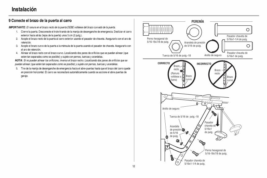
12
Instalación
9 Conecte el brazo de la puerta al carro
IMPORTANTE: El ranura en el brazo recto de la puerta DEBE voltéese del brazo curvado de la puerta.
1. Cierre la puerta. Desconecte el trole tirando de la manija de desenganche de emergencia. Deslizar el carroexterior hacia atrás (lejos de la puerta) unos 5 cm (2 pulg.).
2. Acople el brazo recto de la puerta al carro exterior usando el pasador de chaveta. Asegurarlo con el aro deretención.
3. Acople el brazo curvo de la puerta a la ménsula de la puerta usando el pasador de chaveta. Asegurarlo conel aro de retención.
4. Alinear el brazo recto con el brazo curvo. Localizando dos pares de orificios que se puedan alinear (queesten tan separados como se posible) y sujete con pernos, tuercas y arandelas.
NOTA: Si no pueden alinear los orificions, inverso el brazo rectro. Localizando dos pares de orificios que sepuedan alinear (que esten tan separados como se posible) y sujete con pernos, tuercas y arandelas.
5. Tire de la manija de desenganche de emergencia hacia el abre-puertas hasta que el brazo del carro quedeen posición horizontal. El carro se reconectará automáticamente cuando se accione el abre-puertas degaraje.
Brazo
recto
Brazo
curvo
(Ranura
voltéese a
fuera)
CORRECTO
Brazo
recto
Brazo
curvo
INCORRECTO
Pasador chaveta de
5/16x1-1/4 de pulg.
Anillo de seguro
Pasador
chaveta de
5/16x1
de pulg.
Tuerca de 5/16 de pulg.-18
Arandela
de presión
de 5/16
de pulg.
Perno hexagonal de
5/16-18x7/8 de pulg.
PERENÍA
Perno hexagonal de
5/16-18x7/8 de pulg.
Tuerca de 5/16 de pulg.-18
Arandela de presión
de 5/16 de pulg.
Pasador chaveta de
5/16x1 de pulg.
Pasador chaveta de
5/16x1-1/4 de pulg.
Anillo de seguro
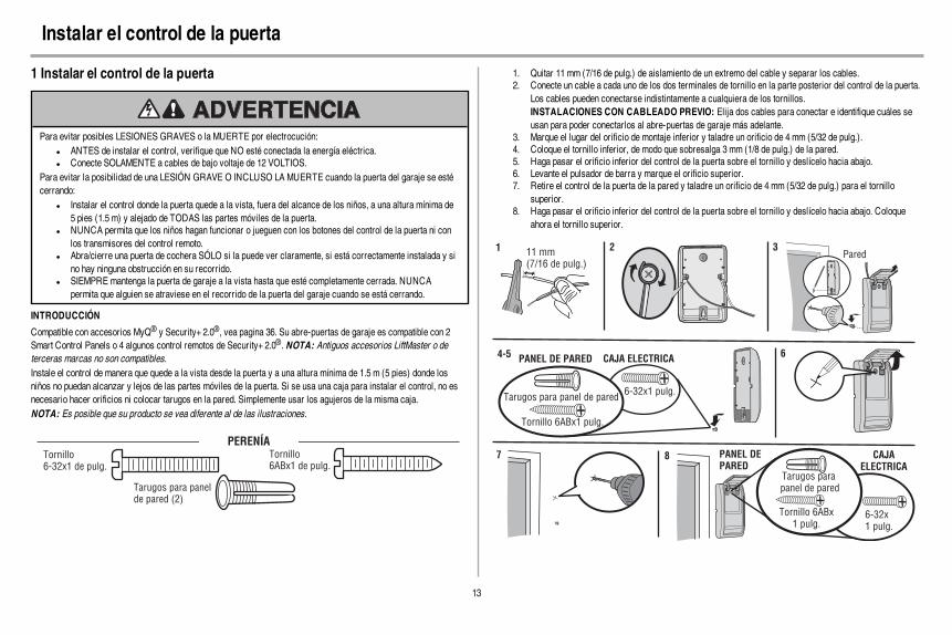
13
Instalar el control de la puerta
1 Instalar el control de la puerta
Para evitar posibles LESIONES GRAVES o la MUERTE por electrocución:l ANTES de instalar el control, verifique que NO esté conectada la energía eléctrica.l Conecte SOLAMENTE a cables de bajo voltaje de 12 VOLTIOS.
Para evitar la posibilidad de una LESIÓN GRAVE O INCLUSO LA MUERTE cuando la puerta del garaje se estécerrando:
l Instalar el control donde la puerta quede a la vista, fuera del alcance de los niños, a una altura mínima de5 pies (1.5 m) y alejado de TODAS las partes móviles de la puerta.
l NUNCA permita que los niños hagan funcionar o jueguen con los botones del control de la puerta ni conlos transmisores del control remoto.
l Abra/cierre una puerta de cochera SÓLO si la puede ver claramente, si está correctamente instalada y sino hay ninguna obstrucción en su recorrido.
l SIEMPRE mantenga la puerta de garaje a la vista hasta que esté completamente cerrada. NUNCApermita que alguien se atraviese en el recorrido de la puerta del garaje cuando se está cerrando.
INTRODUCCIÓN
Compatible con accesorios MyQ® y Security+ 2.0®, vea pagina 36. Su abre-puertas de garaje es compatible con 2Smart Control Panels o 4 algunos control remotos de Security+ 2.0®. NOTA: Antiguos accesorios LiftMaster o deterceras marcas no son compatibles.Instale el control de manera que quede a la vista desde la puerta y a una altura mínima de 1.5 m (5 pies) donde losniños no puedan alcanzar y lejos de las partes móviles de la puerta. Si se usa una caja para instalar el control, no esnecesario hacer orificios ni colocar tarugos en la pared. Simplemente usar los agujeros de la misma caja.NOTA: Es posible que su producto se vea diferente al de las ilustraciones.
PERENÍATornillo6ABx1 de pulg.
Tarugos para panelde pared (2)
Tornillo6-32x1 de pulg.
1. Quitar 11 mm (7/16 de pulg.) de aislamiento de un extremo del cable y separar los cables.2. Conecte un cable a cada uno de los dos terminales de tornillo en la parte posterior del control de la puerta.
Los cables pueden conectarse indistintamente a cualquiera de los tornillos.INSTALACIONES CON CABLEADO PREVIO: Elija dos cables para conectar e identifique cuáles seusan para poder conectarlos al abre-puertas de garaje más adelante.
3. Marque el lugar del orificio de montaje inferior y taladre un orificio de 4 mm (5/32 de pulg.).4. Coloque el tornillo inferior, de modo que sobresalga 3 mm (1/8 de pulg.) de la pared.5. Haga pasar el orificio inferior del control de la puerta sobre el tornillo y deslícelo hacia abajo.6. Levante el pulsador de barra y marque el orificio superior.7. Retire el control de la puerta de la pared y taladre un orificio de 4 mm (5/32 de pulg.) para el tornillo
superior.8. Haga pasar el orificio inferior del control de la puerta sobre el tornillo y deslícelo hacia abajo. Coloque
ahora el tornillo superior.
11 mm (7/16 de pulg.)
Pared1 2 3
PANEL DE PARED CAJA ELECTRICA
Tornillo 6ABx1 pulg.
6-32x1 pulg.Tarugos para panel de pared
4-5 6
6-32x1 pulg.
8 PANEL DE
PARED
Tornillo 6ABx1 pulg.
Tarugos para panel de pared
7 CAJA
ELECTRICA

14
Instalar el control de la puerta
2 Cableado desde el control hasta el abre-puertas de garaje
PERENÍA
Grapas con
aislamiento
(no mostrado)
INSTALACIONES CON CABLEADO PREVIO: Al tender el cableado del control de la puerta al abre-puertas degaraje, asegúrese de usar los mismos cables que están conectados al control de la puerta.
1. Tienda los cables blanco y rojo/blanco entre el control de la puerta y el abre-puertas de garaje. Fijar elcable a la pared y al techo con los broches (no aplicable a instalaciones con cajas de conexión niprecableadas). No perfore el cable con las grapas ya que podría causar un cortocircuito o la apertura delcircuito.
2. Pele 11 mm (7/16 de pulg.) del extremo del cable cerca del abre-puertas de garaje.3. Conecte el cable a los terminales rojo y blanco del abre-puertas de garaje. Para conectar o desconectar un
cable, empujar la pestaña con la punta de un destornillador.
11 mm (7/16 de pulg.)2
3
1
Grapas
BL
AN
CO
RO
JO
BL
AN
CO
GR
IS
3 Colocación de las etiquetas de advertencia
1. Con tachuelas o grapas, coloque en la pared cerca del control de la puerta una etiqueta de advertenciasobre el riesgo de quedar atrapado.
2. Coloque la etiqueta de prueba de reversa de seguridad y apertura manual en un lugar a la vista del ladointerno de la puerta del garaje.
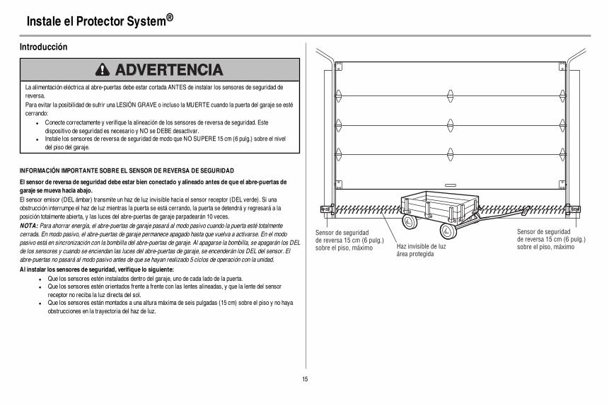
15
Instale el Protector System®
Introducción
La alimentación eléctrica al abre-puertas debe estar cortada ANTES de instalar los sensores de seguridad dereversa.Para evitar la posibilidad de sufrir una LESIÓN GRAVE o incluso la MUERTE cuando la puerta del garaje se estécerrando:
l Conecte correctamente y verifique la alineación de los sensores de reversa de seguridad. Estedispositivo de seguridad es necesario y NO se DEBE desactivar.
l Instale los sensores de reversa de seguridad de modo que NO SUPERE 15 cm (6 pulg.) sobre el niveldel piso del garaje.
INFORMACIÓN IMPORTANTE SOBRE EL SENSOR DE REVERSA DE SEGURIDAD
El sensor de reversa de seguridad debe estar bien conectado y alineado antes de que el abre-puertas degaraje se mueva hacia abajo.El sensor emisor (DEL ámbar) transmite un haz de luz invisible hacia el sensor receptor (DEL verde). Si unaobstrucción interrumpe el haz de luz mientras la puerta se está cerrando, la puerta se detendrá y regresará a laposición totalmente abierta, y las luces del abre-puertas de garaje parpadearán 10 veces.NOTA: Para ahorrar energía, el abre-puertas de garaje pasará al modo pasivo cuando la puerta esté totalmentecerrada. En modo pasivo, el abre-puertas de garaje permanece apagado hasta que vuelva a activarse. En el modopasivo está en sincronización con la bombilla del abre-puertas de garaje. Al apagarse la bombilla, se apagarán los DELde los sensores y cuando se enciendan las luces del abre-puertas de garaje, se encenderán los DEL del sensor. Elabre-puertas no pasará al modo pasivo antes de que se hayan realizado 5 ciclos de operación con la unidad.
Al instalar los sensores de seguridad, verifique lo siguiente:l Que los sensores estén instalados dentro del garaje, uno de cada lado de la puerta.l Que los sensores estén orientados frente a frente con las lentes alineadas, y que la lente del sensor
receptor no reciba la luz directa del sol.l Que los sensores están montados a una altura máxima de seis pulgadas (15 cm) sobre el piso y no haya
obstrucciones en la trayectoria del haz de luz.
Haz invisible de luz
área protegida
Sensor de seguridad
de reversa 15 cm (6 pulg.)
sobre el piso, máximo
Sensor de seguridad
de reversa 15 cm (6 pulg.)
sobre el piso, máximo

16
Instale el Protector System®
1 Instalación de los sensores de reversa de seguridad
PERENÍA
Perno de cochede 1/4 de pulg.-20x1/2 de pulg.
Tuercamariposa de1/4 de pulg.-20
Puede conectar los sensores de reversa de seguridad al carril de la puerta, a la pared o al piso. Si las mensulas noquedan firmemente en la guia de la puerta, es mejor instalarlas sobre la pared. Opte por uno de los siguientes tipos deinstalación.
OPCIÓN A INSTALACIÓN EN LA CARRIL DE LA PUERTA
1. Deslice los brazos curvos de la ménsula del sensor sobre el borde del carril de la puerta. Colóquelos ensu posición de modo que la ménsula del sensor quede al ras del carril.
2. Introduzca el perno de coche en la ranura correspondiente de cada sensor.3. Introduzca el perno en el orificio de la ménsula del sensor y fije con tuercas mariposa. Las lentes de ambos
sensores deben quedar frente a frente. Verifique que la ménsula del sensor no obstruya las lentes.
No masde 15 cm(6 pulg.) Perno de coche
de 1/4 de pulg.- 20x1/2 de pulg.
Tuercamariposa de1/4 de pulg.-20
1 2 3
OPCIÓN B INSTALACIÓN EN LA PAREDSi fuera necesario más espacio puede utilizarse una ménsula de extensión (no provista) o bloques de madera.Cerciórese de que cada ménsula tenga la misma cantidad de espacio para que queden alineadas correctamente.
1. Coloque la ménsula del sensor contra la pared, con los brazos curvos hacia la puerta. Verifique que quedesuficiente espacio para que el haz no tenga obstrucciones. Marque los orificios.
2. Taladre los orificios de 3/16 pulgadas de diámetro para cada ménsula del sensor y sujete las ménsulas delsensor a la pared con tornillos de cabeza cuadrada o pijas (no provistos).
3. Introduzca el perno de coche en la ranura correspondiente de cada sensor.4. Introduzca el perno en el orificio de la ménsula del sensor y fije con tuercas mariposa. Las lentes de ambos
sensores deben quedar frente a frente. Verifique que la ménsula del sensor no obstruya las lentes.
(no incluye)
No masde 15 cm(6 pulg.)
1 2
(no incluye)
LentePerno decoche 1/4-20x1/2de pulg.
Tuerca mariposa1/4 de pulg. -20
3 4
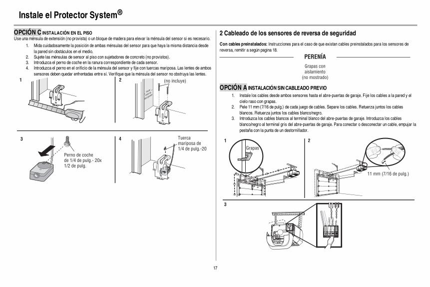
17
Instale el Protector System®
OPCIÓN C INSTALACIÓN EN EL PISOUse una ménsula de extensión (no provista) o un bloque de madera para elevar la ménsula del sensor si es necesario.
1. Mida cuidadosamente la posición de ambas ménsulas del sensor para que haya la misma distancia desdela pared sin obstáculos en el medio.
2. Sujete las ménsulas de sensor al piso con sujetadores de concreto (no provistos).3. Introduzca el perno de coche en la ranura correspondiente de cada sensor.4. Introduzca el perno en el orificio de la ménsula del sensor y fije con tuercas mariposa. Las lentes de ambos
sensores deben quedar enfrentadas entre sí. Verifique que la ménsula del sensor no obstruya las lentes.
(no incluye)1 2
Perno de cochede 1/4 de pulg.- 20x1/2 de pulg.
Tuercamariposa de1/4 de pulg.-20
3 4
2 Cableado de los sensores de reversa de seguridad
Con cables preinstalados: Instrucciones para el caso de que existan cables preinstalados para los sensores dereversa, remitir a según pagina 18.
PERENÍA
Grapas con
aislamiento
(no mostrado)
OPCIÓN A INSTALACIÓNSINCABLEADO PREVIO1. Instale los cables desde ambos sensores hasta el abre-puertas de garaje. Fije los cables a la pared y el
cielo raso con grapas.2. Pele 11 mm (7/16 de pulg.) de cada juego de cables. Separe los cables. Retuerza juntos los cables
blancos. Retuerza juntos los cables blanco/negro.3. Introduzca los cables blancos al terminal blanco del abre-puertas de garaje. Introduzca los cables
blanco/negro al terminal gris del abre-puertas de garaje. Para conectar o desconectar un cable, empujar lapestaña con la punta de un destornillador.
RO
JO
BLA
NC
O
BLA
NC
O
GR
IS
1 2
3
Grapas
BLA
NC
OB
LA
NC
O
GR
ISG
RIS
11 mm (7/16 de pulg.)

18
Instale el Protector System®
OPCIÓN B INSTALACIÓNCONCABLEADO PREVIO1. Corte el extremo del cable del sensor de reversa de seguridad dejando cable suficiente para que llegue a
los cables preinstalados en la pared.2. Separe los cables del sensor de reversa de seguridad y pele 11 mm (7/16 de pulg.) de cada extremo. Elija
dos de los cables preinstalados y pele 11 mm (7/16 de pulg.) de cada extremo. Asegúrese de elegir elmismo color de cable preinstalado para cada sensor.
3. Conecte los cables preinstalados con los cables del sensor, usando capuchones de empalme. Verifiqueque los colores correspondan a cada sensor. Por ejemplo, el cable blanco se conecta con el cable amarilloy el cable blanco/negro se conecta con el cable púrpura.
4. En la abre-puertas de garaje, pele 11 mm (7/16 de pulg.) de cada extremo de los cables elegidospreviamente para los sensores de reversa de seguridad. Retuerza juntos los cables de colores similares.
5. Introduzca los cables conectados con los cables blancos del sensor de seguridad con el el terminal blancoen el abre-puertas de garaje. Introduzca los cables conectado a los cables por el sensor de seguridadblanco/negro al el terminal gris en la abre-puertas de garaje.
Cables de sensor
de seguridad
de reversa
Cables
preinstalados
Blanco
Blanco/Negro
Amarillo (por ejemplo)
Purpura (por ejemplo)
No incluye
Cables preinstalados
Cables de sensor de seguridad de reversa
11 mm(7/16 de pulg.)
Amarillo
Purpura
1
3
4
11 mm(7/16 de pulg.)
2
Amarillo
(por ejemplo)
Purpura
(por ejemplo)
Para insertir o soltar el cable,
empuje la lengüeta hacia dentro con
la punta de un destornillador.
5
RO
JO
BL
AN
CO
BL
AN
CO
GR
ISD
WRO
JO
RE
BL
AN
CO
BL
AN
CO
GR
ISG
RIS

19
Energía
1 Conectar la alimentación
Para evitar la posibilidad de una LESIÓN GRAVE O INCLUSO LA MUERTE por electrocución o incendio:l Asegúrese de que el abridor de la puerta NO esté conectado a la energía eléctrica y desconecte la
energía eléctrica al circuito ANTES de quitar la cubierta para establecer la conexión del cableadopermanente.
l Tanto la instalación como el cableado de la puerta del garaje DEBEN cumplir con TODOS los códigoslocales eléctricos y de construcción.
l NUNCA use una extensión ni un adaptador de dos hilos, tampoco modifique la clavija para poderenchufarla. Asegúrese de que el abre-puertas esté puesto a tierra.
Para evitar problemas con la instalación, no opere elabre-puertas de garaje ahora.Para reducir el riesgo de descarga eléctrica, su abridor dela puerta de cochera viene con una clavija de conexión atierra de tres patas. Esta clavija sólo se puede conectar auna toma de corriente puesta a tierra y con tres entradas.Si la clavija no entra en la toma de corriente que ustedtiene, diríjase a un electricista profesional para que instalela toma de corriente correcta.
HAY DOS OPCIONES PARA CONECTAR LA ENERGÍA ELÉCTRICA:
1. Enchufe el abre-puertas a un tomacorrientecon puesta a tierra.
2. Por el momento, NO ponga en funcionamientoel abre-puertas.
CONEXIÓN TÍPICA
Si la reglamentación local exige que su abre-puertas tenga cableado permanente, siga los siguientes pasos.Para hacer una conexión permanente a través de la entrada de 7/8 de pulg. en la parte superior del motor(según las normas municipales vigentes):
Cableado al la tabla de filtro (Modelos fabrica antes de Octubre2012):
1. Verifique que la energía NO esté conectada al abre-puertas y desconecte la energía eléctrica al circuito.
2. Quite la tapa del abre-puertas de garaje y colóquela a uncostado.
3. Quitar el terminal verde de puesta a tierra.4. Corte el negro y blanco cable. Quitar 1 cm (1/2 de pulg.)
de aislamiento, 7.5 cm (3 pulg.) antes de terminales.5. Quitar el cordón eléctrico del abre-puerta.6. Instale un conducto o adaptador de cable flexible en el
orificio de 7/8 de pulg.7. Pasar los cables por el conducto, cortarlos a la medida
correspondiente y quitar el aislamiento.8. Conecte los capuchones de empalme suministrados.
Conecte el cable de puesta a tierra al tornillo verde depuesta a tierra. El abre-puertas debe estar puesto a tierra.
9. Atar el cable con los lazos prensacables para que no entreen contacto con las partes en movimiento.
10. Volver a colocar la tapa. Por el momento, NO ponga enfuncionamiento el abre-puertas.
Lengüeta de tierra
Tornillo de tierra
verde
Cable de tierra
Cable
negro
Cable blanco
TABLA DE FILTRO
Lazos
Cableado al la bloque terminal (Modelos fabrica después deOctubre 2012):
1. Quite los tornillos de la tapa del abre-puertas y deje lacubierta hacia un lado.
2. Quite el cable de tres entradas.3. Conecte el cable (línea) negro al tornillo del terminal de
cobre, el cable blanco (neutral) al tornillo del terminalcolor plata, y el cable a tierra al tornillo verde de la puestaa tierra. El abre-puertas debe estar puesto a tierra.
4. Volver a colocar la tapa.
Terminal depuesta a tierra
Tornilloverde depuestaa tierra
Cable detierra
Cable blanco
CONEXIÓN PERMANENTE
Cablenegro
Cablenegro
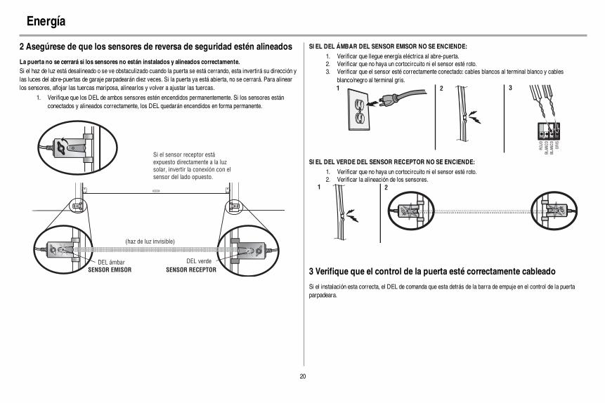
20
Energía
2 Asegúrese de que los sensores de reversa de seguridad estén alineados
La puerta no se cerrará si los sensores no están instalados y alineados correctamente.Si el haz de luz está desalineado o se ve obstaculizado cuando la puerta se está cerrando, esta invertirá su dirección ylas luces del abre-puertas de garaje parpadearán diez veces. Si la puerta ya está abierta, no se cerrará. Para alinearlos sensores, aflojar las tuercas mariposa, alinearlos y volver a ajustar las tuercas.
1. Verifique que los DEL de ambos sensores estén encendidos permanentemente. Si los sensores estánconectados y alineados correctamente, los DEL quedarán encendidos en forma permanente.
DEL verdeDEL ámbar
Si el sensor receptor está
expuesto directamente a la luz
solar, invertir la conexión con el
sensor del lado opuesto.
(haz de luz invisible)
SENSOR EMISOR SENSOR RECEPTOR
SI EL DEL ÁMBAR DEL SENSOR EMISOR NO SE ENCIENDE:
1. Verificar que llegue energía eléctrica al abre-puerta.2. Verificar que no haya un cortocircuito ni el sensor esté roto.3. Verificar que el sensor esté correctamente conectado: cables blancos al terminal blanco y cables
blanco/negro al terminal gris.
ROJO
BLANCO
BLANCO
GRIS
321
SI EL DEL VERDE DEL SENSOR RECEPTOR NO SE ENCIENDE:
1. Verificar que no haya un cortocircuito ni el sensor esté roto.2. Verificar la alineación de los sensores.
1 2
3 Verifique que el control de la puerta esté correctamente cableado
Si el instalación esta correcta, el DEL de comanda que esta detrás de la barra de empuje en el control de la puertaparpadeara.

21
Ajustes
Introducción
Si el sistema de reversa de seguridad no se ha instalado debidamente, las personas (y los niños pequeños enparticular) podrían sufrir LESIONES GRAVES o incluso la MUERTE cuando se cierre la puerta del garaje.
l El ajuste incorrecto de los límites del recorrido de la puerta del garaje interferirá con la operaciónadecuada del sistema de reversa de seguridad.
l Después de llevar a cabo cualquier ajuste, SE DEBE probar el sistema de reversa de seguridad. Lapuerta DEBE retroceder al entrar en contacto con un objeto de 3.8 cm (1 1/2 de pulg.) de altura (o de 5x 10 cm [2 x 4 pulg.] acostado en el piso).
Para evitar que los vehículos sufran daños, cerciórese de que cuando la puerta esté completamente abiertahaya espacio suficiente.
El abre-puertas de garaje está diseñado con controles electrónicos que facilitan su instalación y regulación. Puederegularse el punto de parada de la puerta en su posición abierta (arriba) y cerrada (abajo). Los controles electrónicosdetectan la fuerza que es necesaria para abrir y para cerrar la puerta. La fuerza se ajusta automáticamente cuando seprograma el recorrido.NOTA: Si algo interfiere con el recorrido de la puerta en su trayectoria hacia arriba, la puerta se detendrá. La puertainvertirá su dirección de movimiento si encuentra una interferencia en su movimiento hacia abajo.
ARRIBA
(abierta)
ABAJO
(cerrado)
BOTONES DE PROGRAMACIÓN
Los botones de programación están en el panel a la izquierda del abre-puertas de garaje y se utilizan para programar elrecorrido de la puerta. Cuando programar, los botones de arriba y abajo pueden utilizarse para mover la puerta cuandosea necesario.
Botón de
SUBIDA
Botón de
regulación
Botón de
BAJADA
BOTONES DE PROGRAMACIÓN
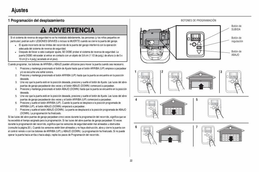
22
Ajustes
1 Programación del desplazamiento
Si el sistema de reversa de seguridad no se ha instalado debidamente, las personas (y los niños pequeños enparticular) podrían sufrir LESIONES GRAVES o incluso la MUERTE cuando se cierre la puerta del garaje.
l El ajuste incorrecto de los límites del recorrido de la puerta del garaje interferirá con la operaciónadecuada del sistema de reversa de seguridad.
l Después de llevar a cabo cualquier ajuste, SE DEBE probar el sistema de reversa de seguridad. Lapuerta DEBE retroceder al entrar en contacto con un objeto de 3.8 cm (1 1/2 de pulg.) de altura (o de 5 x10 cm [2 x 4 pulg.] acostado en el piso).
Cuando programar, los botones de ARRIBA y ABAJO pueden utilizarse para mover la puerta cuando sea necesario.
1. Presione y mantenga presionado el botón de Ajuste hasta que el botón ARRIBA (UP) empiece a parpadeary/o se escuche una señal sonora.
2. Presione y mantenga presionado el botón ARRIBA (UP) hasta que la puerta se encuentre en la posicióndeseada.
3. Una vez que la puerta esté en la posición deseada, presione y suelte el botón de Ajuste. Las luces del abre-puertas de garaje parpadearán dos veces y el botón ABAJO (DOWN) comenzará a parpadear.
4. Presione y mantenga presionado el botón ABAJO (DOWN) hasta que la puerta se encuentre en la posicióndeseada.
5. Una vez que la puerta esté en la posición deseada, presione y suelte el botón de Ajuste. Las luces del abre-puertas de garaje parpadearán dos veces y el botón ARRIBA (UP) comenzará a parpadear.
6. Presione y suelte el botón ARRIBA (UP). Cuando la puerta se desplace a la posición programada deARRIBA (UP), el botón ABAJO (DOWN) empezará a parpadear.
7. Presione y suelte el botón ABAJO (DOWN). La puerta se desplazará a la posición programada de ABAJO(DOWN). La programación ha finalizado.
Si las luces del abre-puertas de garaje parpadean cinco veces durante la programación del recorrido, significa que seha excedido el tiempo asignado para la programación. Si las luces del abre-puertas de garaje parpadean 10 vecesdurante la programación del recorrido, significa que los sensores de seguridad están mal alineados u obstruidos(consulte la página 20 ). Cuando los sensores estén bien alineados y no haya obstrucción, abra y cierre la puerta conel control remoto o con los botones de ARRIBA (UP) y ABAJO (DOWN). La programación ha finalizado. Si no puedeoperar la puerta hacia arriba o hacia abajo, repita los pasos de Programación del recorrido.
Botón de
SUBIDA
Botón de
regulación
Botón de
ABAJO
BOTONES DE PROGRAMACIÓN
1 2 3
4 5
6 7

23
Ajustes
2 Pruebe el sistema de reversa de seguridad
Si el sistema de reversa de seguridad no se ha instalado debidamente, las personas (y los niños pequeños enparticular) podrían sufrir LESIONES GRAVES o incluso la MUERTE cuando se cierre la puerta del garaje.
l El sistema de reversa de seguridad SE DEBE probar cada mes.l Después de llevar a cabo cualquier ajuste, SE DEBE probar el sistema de reversa de seguridad. La
puerta DEBE retroceder al entrar en contacto con un objeto de 3.8 cm (1 1/2 de pulg.) de altura (o de 5 x10 cm [2 x 4 pulg.] acostado en el piso).
1. Con la puerta completamente abierta, coloque una tabla de 3.8 cm (1 1/2 de pulg.) de altura (o de 5 x 10 cm[2 x 4 pulg.] acostada en el piso), centrada abajo de la puerta del garaje.
2. Presione el botón pulsador del control remoto para cerrar la puerta. La puerta DEBE retroceder al hacercontacto con la tabla.
Si la puerta se detiene y no invierte su dirección al tocar la obstrucción, aumente la distancia de cierre (véase Ajustepaso 1). Repita la prueba. Cuando la puerta retroceda al hacer contacto con la tabla de 3.8 cm (1 1/2 de pulg.), quítela yabra/cierre la puerta tres o cuatro veces para probar el ajuste. Si al abre-puertas continúa sin revertir la dirección,llame a un técnico profesional para solucionar el problema.
1 2
3 Pruebe el sistema Protector System®
Si un sensor de reversa de seguridad no se ha instalado adecuadamente, las personas (y los niños pequeños enparticular) podrían sufrir LESIONES GRAVES o incluso MORIR al cerrar la puerta del garaje.
1. Abra la puerta. Coloque la caja del abre-puertas de garaje en el recorrido de la puerta.2. Presione el botón pulsador del control remoto para cerrar la puerta. La puerta no se moverá más de 2.5 cm
(una pulgada), y las luces del abre-puertas de garaje parpadearán 10 veces.El abre-puertas de garaje no se cerrará mediante un control remoto si el DEL del sensor de reversa de seguridad estáapagado (alertándolo de que el sensor está mal alineado u obstruido). Si el abre-puertas comanda el cierre de la puertacon una obstrucción presente (y los sensores de seguridad no están instalados a más de 15 cm (6 pulg.) de alturasobre el piso), llame a un técnico especializado para reparar este problema.
1 2
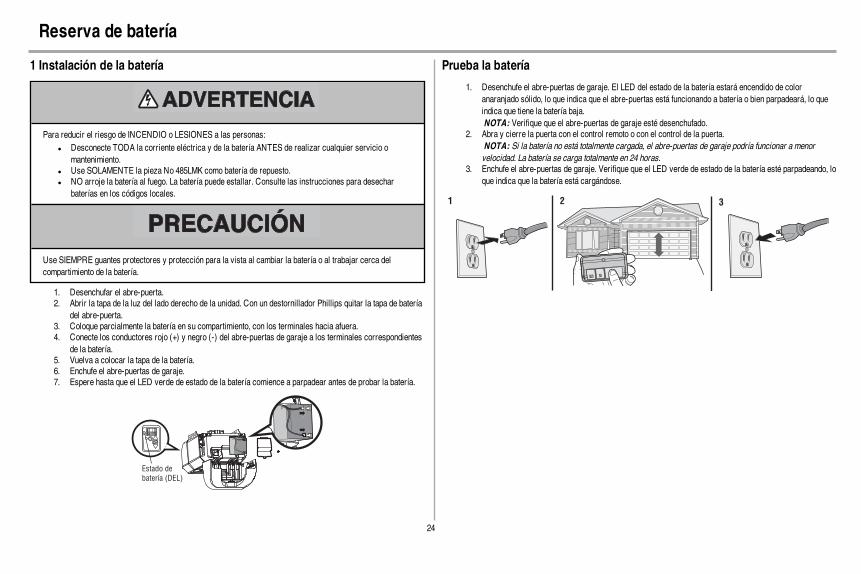
24
Reserva de batería
1 Instalación de la batería
Para reducir el riesgo de INCENDIO o LESIONES a las personas:l Desconecte TODA la corriente eléctrica y de la batería ANTES de realizar cualquier servicio o
mantenimiento.l Use SOLAMENTE la pieza No 485LMK como batería de repuesto.l NO arroje la batería al fuego. La batería puede estallar. Consulte las instrucciones para desechar
baterías en los códigos locales.
Use SIEMPRE guantes protectores y protección para la vista al cambiar la batería o al trabajar cerca delcompartimiento de la batería.
1. Desenchufar el abre-puerta.2. Abrir la tapa de la luz del lado derecho de la unidad. Con un destornillador Phillips quitar la tapa de batería
del abre-puerta.3. Coloque parcialmente la batería en su compartimiento, con los terminales hacia afuera.4. Conecte los conductores rojo (+) y negro (-) del abre-puertas de garaje a los terminales correspondientes
de la batería.5. Vuelva a colocar la tapa de la batería.6. Enchufe el abre-puertas de garaje.7. Espere hasta que el LED verde de estado de la batería comience a parpadear antes de probar la batería.
Estado de
batería (DEL)
Prueba la batería
1. Desenchufe el abre-puertas de garaje. El LED del estado de la batería estará encendido de coloranaranjado sólido, lo que indica que el abre-puertas está funcionando a batería o bien parpadeará, lo queindica que tiene la batería baja.NOTA: Verifique que el abre-puertas de garaje esté desenchufado.
2. Abra y cierre la puerta con el control remoto o con el control de la puerta.NOTA: Si la batería no está totalmente cargada, el abre-puertas de garaje podría funcionar a menorvelocidad. La batería se carga totalmente en 24 horas.
3. Enchufe el abre-puertas de garaje. Verifique que el LED verde de estado de la batería esté parpadeando, loque indica que la batería está cargándose.
1 2 3
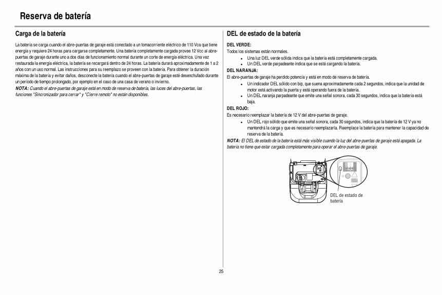
25
Reserva de batería
Carga de la batería
La batería se carga cuando el abre-puertas de garaje está conectado a un tomacorriente eléctrico de 110 Vca que tieneenergía y requiere 24 horas para cargarse completamente. Una batería completamente cargada provee 12 Vcc al abre-puertas de garaje durante uno a dos días de funcionamiento normal durante un corte de energía eléctrica. Una vezrestaurada la energía eléctrica, la batería se recargará dentro de 24 horas. La batería durará aproximadamente de 1 a 2años con un uso normal. Las instrucciones para su reemplazo se proveen con la batería. Para obtener la duraciónmáxima de la batería y evitar daños, desconecte la batería cuando el abre-puertas de garaje esté desenchufado duranteun período de tiempo prolongado, por ejemplo en el caso de una casa de verano o invierno.NOTA: Cuando el abre-puertas de garaje está en modo de reserva de batería, las luces del abre-puertas, lasfunciones "Sincronizador para cerrar" y "Cierre remoto" no están disponibles.
DEL de estado de la batería
DEL VERDE:Todos los sistemas están normales.
l Una luz DEL verde sólida indica que la batería está completamente cargada.l Un DEL verde parpadeante indica que se está cargando la batería.
DEL NARANJA:El abre-puertas de garaje ha perdido potencia y está en modo de reserva de batería.
l Un indicador DEL sólido con bip, que suena aproximadamente cada 2 segundos, indica que la unidad demotor está activando la puerta y está operando fuera de la batería.
l Un DEL naranja parpadeante que emite una señal sonora, cada 30 segundos, indica que la batería estábaja.
DEL ROJO:Es necesario reemplazar la batería de 12 V del abre-puertas de garaje.
l Un DEL rojo sólido que emite una señal sonora, cada 30 segundos, indica que la batería de 12 V ya nomantendrá la carga y que es necesario reemplazarla. Reemplace la batería para mantener la capacidad dereserva de la batería.
NOTA: El DEL de estado de la batería está más visible cuando la luz del abre-puertas de garaje está apagada. Labatería no tiene que estar cargada completamente para operar el abre-puertas de garaje.
DEL de estado de
batería

26
INSTRUCCIONES DE SEGURIDAD IMPORTANTES
Para reducir el riesgo de LESIONES GRAVES o la MUERTE:1. LEA Y SIGA TODAS LAS INSTRUCCIONES Y ADVERTENCIAS.2. SIEMPRE conserve los controles remotos lejos del alcance de los niños. NUNCA permita que los niños
operen o jueguen con los botones del control del abre-puertas de garaje ni con los controles remotos.3. SÓLO active el abre-puertas de garaje siempre y cuando lo puedan ver con claridad, esté debidamente
ajustado y no haya ninguna obstrucción en su recorrido al cerrarse.4. SIEMPRE mantenga la puerta del garaje a la vista y alejada de las personas y objetos hasta que esté
completamente cerrada. NADIE DEBE ATRAVESAR EL RECORRIDO DE LA PUERTA CUANDOESTÁ EN MOVIMIENTO.
5. NADIE DEBE CRUZAR POR DEBAJO DE UNA PUERTA DETENIDA O PARCIALMENTE ABIERTA.6. De ser posible, use el desenganche de emergencia para soltar el carro SÓLO cuando la puerta del
cochera esté CERRADA. Tenga precaución cuando utilice este desenganche con la puerta abierta. Losresortes débiles o rotos o la puerta desequilibrada pueden ocasionar que una puerta abierta caiga rápiday/o inesperadamente y aumentan el riesgo de LESIONES GRAVES o la MUERTE.
7. NUNCA use la manija de emergencia a menos que la entrada a la cochera esté libre de obstrucciones yno haya ninguna persona presente.
8. NUNCA use la manija para jalar la puerta para abrirla o cerrarla. Si el nudo de la cuerda se suelta, ustedpodría caerse.
9. Después de llevar a cabo cualquier ajuste, SE DEBE probar el sistema de reversa de seguridad.
10. El sistema de reversa de seguridad SE DEBE probar cada mes. La puerta del garaje DEBE retroceder alentrar en contacto con un objeto de 1-1/2 de pulg. (3,8 cm) de altura (o de 2 x 4 acostado en el piso). Sino se ajusta el abre-puertas de garaje debidamente, aumentará el riesgo de sufrir LESIONES GRAVESo la MUERTE.
11. MANTENGA SIEMPRE LA PUERTA DEL GARAJE DEBIDAMENTE EQUILIBRADA (vea pagina 1).Es posible que una puerta que no esté bien equilibrada NO funcione en reversa cuando sea necesario, locual puede ocasionar LESIONES GRAVES o la MUERTE.
12. TODAS las reparaciones necesarias para los cables, resortes y otras piezas las DEBE llevar a cabo untécnico profesional en sistemas de puertas, pues TODAS estas piezas están bajo una tensiónEXTREMA.
13. Para evitar LESIONES PERSONALES GRAVES o la MUERTE por electrocución, desconectarTOTALMENTE la energía eléctrica y de la batería ANTES de hacer CUALQUIER trabajo de reparacióno mantenimiento.
14. Este sistema tiene una función de activación por estado pasivo. La puerta podría ponerse en movimientorepentinamente. NADIE DEBE ATRAVESAR EL RECORRIDO DE LA PUERTA CUANDO ESTÁ ENMOVIMIENTO.
15. NO activar el temporizador de cierre en puertas de garaje de una sola pieza o puertas batientes. Usaresta función ÚNICAMENTE con puertas seccionales.
16. CONSERVAR ESTASINSTRUCCIONES.
Operación

27
Funciones
El abre-puertas de garaje tiene varias funciones para que pueda tener más control sobre el funcionamiento de su abre-puertas.Alert2CloseLa función Alert2Close viene con una alerta visual y sonora que avisa que hay una puerta en estado pasivo cerrándose.TEMPORIZADOR DE CIERRE (TTC)El temporizador de cierre cierra automáticamente la puerta después de cierto tiempo, el cual puede ser regulado con elcontrol de puerta. Antes y durante el cierre de la puerta, las luces parpadearán y se escuchará una señal sonora.MyQ®
La tecnología MyQ®utiliza señal de 900MHz para comunicaciones bidireccionales entre el abre-puerta y losaccesorios compatibles con MyQ®. El abre-puertas de garaje es compatible hasta con 16 accesorios MyQ®.CONTROL REMOTOS Y CONTROL DE LA PUERTA DE SECURITY+ 2.0®
El abre-puertas de garaje ya viene programado de fábrica para funcionar con el control remoto, que cambia cada vezque se usa y puede acceder aleatoriamente a más de 100 mil millones de códigos nuevos. Compatible con accesoriosMyQ® y Security+ 2.0®, vea pagina 36.NOTA: Los controles remotos anteriores de LiftMaster, los controles de la puerta y los productos de terceros no soncompatibles.
SECURITY+ 2.0®
AccesoriosCapacidad de la memoria
Controles remotos Hasta 24
Controles de la puerta Hasta 2 Smart Control Panels o 4 algunos controles de puerta Security+ 2.0®
Llaves digitales Hasta 2
THE PROTECTORSYSTEM® (SENSORES DE SEGURIDAD DE REVERSA)Cuando están correctamente instalados y alineados, los sensores de reversa de seguridad detectarán una obstrucciónen el trayecto del haz infrarrojo. Si una obstrucción interrumpe el haz infrarrojo mientras se cierra la puerta, ésta sedetendrá y retrocederá hasta la posición totalmente abierta, y las luces del abre-puertas destellarán 10 veces. Si lapuerta está totalmente abierta, y los sensores no están instalados o están desalineados, la puerta no se cerrará desdeun control remoto. Sin embargo, puede cerrar la puerta si mantiene presionado el botón del control o de la entrada sinllave hasta que la puerta se cierre por completo. Los sensores de reversa de seguridad no afectan el ciclo de apertura.
CONSERVACIÓNDE ENERGÍAPara ahorrar energía, el abre-puertas de garaje pasará al modo pasivo cuando la puerta esté totalmente cerrada. En elmodo pasivo, el abre-puertas de garaje permanece apagado hasta que vuelva a activarse. En el modo pasivo está ensincronización con la bombilla del abre-puertas de garaje. Al apagarse la bombilla, se apagarán los DEL de lossensores y cuando se enciendan las luces del abre-puertas de garaje, se encenderán los DEL del sensor. El abridor dela puerta de cochera no pasará al modo pasivo hasta que haya completado 5 ciclos desde que se accionó.
LUCESLas bombillas del abre-puertas de garaje se encenderán cuando el abre-puertas se enchufe inicialmente, alrestablecerse la energía después de un corte o al activarse el abre-puertas de garaje. Las luces se apagaránautomáticamente después de 4 y medio minutos. Puede usarse una bombilla incandescente A19 (de hasta 100 vatios) ouna bombilla fluorescente de alto rendimiento (CFL) de hasta 26 W (equivalente a 100 vatios) para obtener la máximaeficiencia de energía.Función de luzEl abre-puertas de garaje está equipado con una función adicional: las luces se encenderán si alguien entra por lapuerta del garaje abierta y se interrumpe el haz infrarrojo de los sensores de reversa de seguridad. Para tener máscontrol de las bombillas del abre-puertas de garaje, consulte la página 29.CÓMO USARSUABRE-PUERTAS DE GARAJEEl abre-puerta puede activarse con un control fijo montado en la pared, un control remoto, una llave digital o unaccesorio MyQ®. Al activarse el abre-puerta con la puerta cerrada, la puerta se abrirá. Si hay una obstrucción durantela apertura, la puerta se detendrá. Si la puerta se ha detenido en un posición parcialmente abierta, se va a cerrar. Si elabre-puerta detecta una obstrucción mientras se cierra, la puerta invertirá su dirección de movimiento. Si unaobstrucción interrumpiera el haz del sensor, la luz del sistema se encenderá intermitentemente 10 veces. Sin embargo,puede cerrar la puerta si mantiene presionado el botón del control o de la entrada sin llave hasta que la puerta se cierrepor completo. Los sensores de reversa de seguridad no afectan el ciclo de apertura. El sensor de reversa de seguridaddebe estar bien conectado y alineado antes de que el abre-puerta se mueva hacia abajo.RESERVA DE LA BATERÍAEl sistema de reserva de la batería permite ingresar y salir del garaje, aun cuando no haya energía eléctrica. Cuando elabre-puertas funcione con la batería será más lento, las luces no funcionarán, el DEL de estado de batería seencenderá de color anaranjado y se escuchará una señal sonora cada 2 segundos.

28
Control de la puerta
Montaje del control de puerta
SINCRONIZACIÓN DEL CONTROL DE LA PUERTA
Para sincronizar el control con el abre-puertas de garaje, presione el pulsador de barra hasta que se active elabridor de la puerta de cochera (podría llevar hasta tres intentos). Pruebe el control de la puerta presionando elpulsador de barra. Cada vez que se presiona el pulsador de barra, se activará el mecanismo del abridor de la puertade cochera.
Barra de empuje
Botón “LIGHT” (LUZ)
Sensor de movimiento
Botón “LOCK”
(SEGURO)
DEL de commande
Botón “LEARN”
(Aprendizaje)
DEL de Servicio
PULSADOR
Oprima la barra pulsadora para abrir o cerrar la puerta.
BOTÓN DE LUZ
Oprima el botón de luces para encender o apagar las luces del abre-puertas. Las luces permanecerán encendidashasta que se vuelva a pulsar el botón o hasta que se active el abre-puerta. Después de activar el abre-puerta, las lucesse apagarán después del tiempo programado de espera (programación de fábrica: 4,5 minutos). Este botón no controlalas luces del abre-puerta cuando la puerta está en movimiento.
Las siguientes características son accesibles por levantar la barra de empuje:
PROGRAMAR UN DISPOSITIVO
Cualquier compatible con mandos a distancia, entrada sin llave inalámbrica o accesorios MyQ® pueden serprogramados para la puerta del garaje pulsando el botón de aprendizaje en el Panel de Control de detección demovimiento, vea página 30CERRARLa función de BLOQUEO (LOCK) impide la activación del abre-puertas de garaje con un control remoto pero permiteigualmente la activación desde el control de la puerta y la entrada con llave digital. Esto es útil como medida extra deseguridad cuando no hay nadie en la casa (por ejemplo, durante vacaciones).
LUZ AUTOMÁTICA
Sensor de movimiento (Panel de control con deteccion de movimiento)Esta función viene desactivada de fábrica. Esta función encenderá automáticamente las luces del abre-puertas degaraje al detectar movimiento. Se encenderán durante el período programado y luego se apagarán. Si se desea usar laluz del abre-puertas de garaje permanentemente, es necesario desactivar la función automática para evitar que seapague cuando usted quede fuera del alcance del sensor de movimiento.Función de luzLas luces se encenderán cuando alguien entre por la puerta del garaje y sea interrumpido el haz de los sensores deseguridad.SISTEMA ALERTA DE MANTENIMIENTO (MAS)Esta función ayuda al usuario a asegurarse de que el sistema del abre-puertas de garaje se mantenga en buenascondiciones de funcionamiento. Cuando la puerta del garaje debe ser atendido (aproximadamente 4500 abre-puertasdel garaje ciclos) el comando (amarillo) y servicio (rojo) DEL comenzará a despedir alternativamente hacia adelante yhacia atrás. El ajuste de fábrica para la función MAS está apagado y puede activarse en el momento de la instalación.Comuníquese con su distribuidor de instalación por servicio.
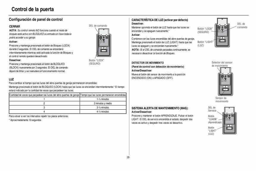
29
Control de la puerta
Configuración de panel de control
CERRARNOTA: Su control remoto NO funciona cuando el modo debloqueo está activo sin BLOQUEO su entrada sin llave todavíapodrá acceder a su garaje.
Activar:Presione y mantenga presionado el botón de Bloqueo (LOCK)durante 2 segundos. El DEL de comando se encenderáintermitentemente mientras esté activada la función de Bloqueo yel control remoto quedará desactivado.Desactivar:Presione y mantenga presionado el botón de BLOQUEO(BLOCK) nuevamente por 2 segundos. El DEL de comandodejará de titilar y se reanudará el funcionamiento normal.
Botón “LOCK”
(SEGURO)
DEL de comando
LUZPara cambiar el tiempo que las luces del abre-puertas de garaje permanecen encendidas:Mantenga presionado el botón de BLOQUEO (LOCK) hasta que las luces se enciendan intermitentemente.* El tiempoestará indicado por la cantidad de veces que parpadeen las luces.
Cantidad de veces que parpadean las luces del abre-puertas de garaje Tiempo que las luces permanecen encendidas
1 1-½minutos
2 2 minutos y medio
3 3-½minutos
4 4-½minutos
Para volver a ver los intervalos repetir los pasos anteriores.* Aproximadamente 10 segundos
CARACTERÍSTICADE LUZ (activar por defecto)Desactivar:Mantener oprimido el botón de LUZ hasta que las luces seenciendan y se apaguen nuevamente.*Activar:Comience con las luces encendidas del abre-puertas de garaje.Mantenga presionado el botón de LUZ (LIGHT) hasta que lasluces se apaguen y se enciendan nuevamente.*NOTA: Si el DEL de comando parpadea continuamente, esnecesario desactivar la función de Bloqueo.
Botón “LOCK”
(SEGURO)
Botón “LIGHT”
(LUZ)
DEL de
comando
DETECTOR DE MOVIMIENTO(Panel de control con detección de movimiento)Activar/Desactivar:Mueva el botón del sensor de movimiento a la posiciónENCENDIDO (ON) o APAGADO (OFF).
Selector del sensor
de movimiento
Sensor de
movimiento
SISTEMA ALERTA DE MANTENIMIENTO (MAS):Activar/Desactivar:Presione y mantener el botón APRENDIZAJE. Pulsar el botónLIGHT. El DEL de servicio encendida el estado; despedir dosveces es activo y despedir tres veces es desactivo.
Botón
“LEARN”
(Aprendizaje)
Botón
“LIGHT”
(LUZ)
DEL de
Servicio
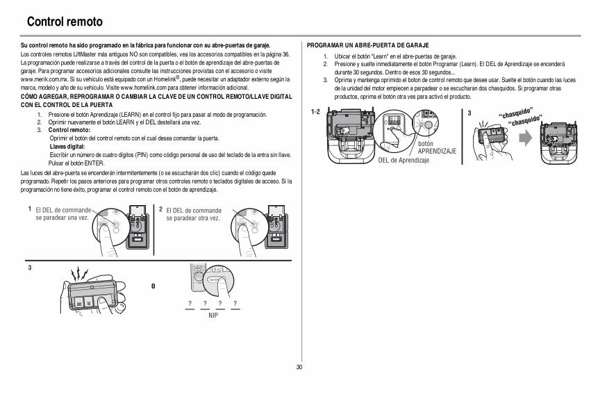
30
Control remoto
Su control remoto ha sido programado en la fábrica para funcionar con su abre-puertas de garaje.Los controles remotos LiftMaster más antiguos NO son compatibles, vea los accesorios compatibles en la página 36.La programación puede realizarse a través del control de la puerta o el botón de aprendizaje del abre-puertas degaraje. Para programar accesorios adicionales consulte las instrucciones provistas con el accesorio o visitewww.merik.com.mx. Si su vehículo está equipado con un Homelink®, puede necesitar un adaptador externo según lamarca, modelo y año de su vehículo. Visite www.homelink.com para obtener información adicional.CÓMO AGREGAR, REPROGRAMAR O CAMBIAR LA CLAVE DE UN CONTROL REMOTO/LLAVE DIGITALCON EL CONTROL DE LA PUERTA
1. Presione el botón Aprendizaje (LEARN) en el control fijo para pasar al modo de programación.2. Oprimir nuevamente el botón LEARN y el DEL destellará una vez.3. Control remoto:
Oprimir el botón del control remoto con el cual desea comandar la puerta.Llaves digital:Escribir un número de cuatro dígitos (PIN) como código personal de uso del teclado de la entra sin llave.Pulsar el botón ENTER.
Las luces del abre-puerta se encenderán intermitentemente (o se escucharán dos clic) cuando el código quedeprogramado. Repetir los pasos anteriores para programar otros controles remoto o teclados digitales de acceso. Si laprogramación no tiene éxito, programar el control remoto con el botón de aprendizaje.
El DEL de commandese paradear una vez.
El DEL de commandese paradear otra vez.
1 2
O
NIP
? ? ? ?
4GHI 5JKL
7PRS 8TUV 9WXY
0 QZ* #
ENTER
0 QZ*
#
ENTER
6 MNO
3
PROGRAMAR UN ABRE-PUERTA DE GARAJE
1. Ubicar el botón "Learn" en el abre-puertas de garaje.2. Presione y suelte inmediatamente el botón Programar (Learn). El DEL de Aprendizaje se encenderá
durante 30 segundos. Dentro de esos 30 segundos...3. Oprima y mantenga oprimido el boton de control remoto que desee usar. Suelte el botón cuando las luces
de la unidad del motor empiecen a parpadear o se escucharan dos chasquidos. Si programar otrasproductos, oprima el botón otra ves para activó el producto.
DEL de Aprendizaje
botón
APRENDIZAJE
“chasquido
”
“chasquido
”1-2 3
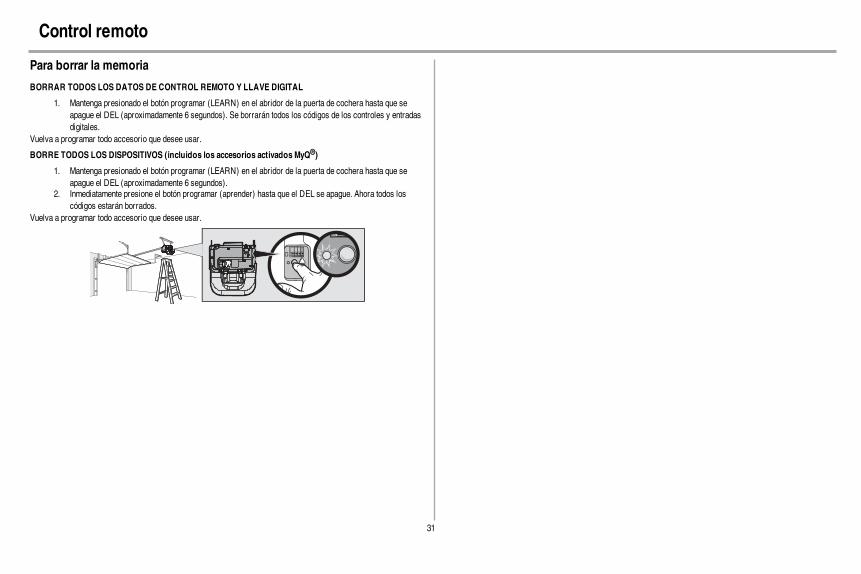
31
Control remoto
Para borrar la memoria
BORRAR TODOS LOS DATOS DE CONTROL REMOTO Y LLAVE DIGITAL
1. Mantenga presionado el botón programar (LEARN) en el abridor de la puerta de cochera hasta que seapague el DEL (aproximadamente 6 segundos). Se borrarán todos los códigos de los controles y entradasdigitales.
Vuelva a programar todo accesorio que desee usar.
BORRE TODOS LOS DISPOSITIVOS (incluidos los accesorios activados MyQ®)
1. Mantenga presionado el botón programar (LEARN) en el abridor de la puerta de cochera hasta que seapague el DEL (aproximadamente 6 segundos).
2. Inmediatamente presione el botón programar (aprender) hasta que el DEL se apague. Ahora todos loscódigos estarán borrados.
Vuelva a programar todo accesorio que desee usar.
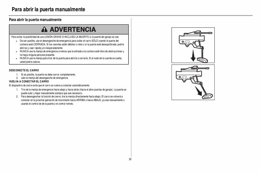
32
Para abrir la puerta manualmente
Para abrir la puerta manualmente
Para evitar la posibilidad de una LESIÓN GRAVE O INCLUSO LA MUERTE si la puerta del garaje se cae:l De ser posible, use el desenganche de emergencia para soltar el carro SÓLO cuando la puerta del
cochera esté CERRADA. Si los resortes están débiles o rotos o si la puerta está desequilibrada, podríaabrirse y caer rápida y/o inesperadamente.
l NUNCA use la manija de emergencia a menos que la entrada a la cochera esté libre de obstrucciones yno haya ninguna persona presente.
l NUNCA use la manija para tirar de la puerta para abrirla o cerrarla. Si el nudo de la cuerda se suelta,usted podría caerse.
DESCONECTE EL CARRO
1. Si es posible, la puerta se debe cerrar completamente.2. Jale la manija del desenganche de emergencia.
VUELVA A CONECTAR EL CARROEl dispositivo de cierre evita que el carro se vuelva a conectar automáticamente.
1. Tire de la manija de emergencia hacia abajo y hacia atrás (hacia el abre-puertas de garaje). La puerta sepuede subir y bajar manualmente siempre que sea necesario.
2. Para desenganchar la función de cierre, tire la manija directamente hacia abajo. El carro se volverá aconectar en la próxima operación de movimiento hacia ARRIBA o hacia ABAJO, ya sea manualmente ousando el control de de la puerta o el control remoto.
NOTICE
NOTICE
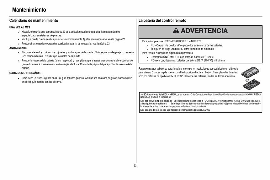
33
Mantenimiento
Calendario de mantenimiento
UNA VEZ AL MES
l Haga funcionar la puerta manualmente. Si esta desbalanceada o se pandea, llame a un técnicoespecializado en sistemas de puertas.
l Verifique que la puerta se abra y se cierre completamente.Ajustar si es necesario, vea la página 22.
l Pruebe el sistema de reversa de seguridad.Ajustar si es necesario, vea la página 23.
ANUALMENTE
l Ponga aceite en los rodillos, los cojinetes y las bisagras de la puerta. El abre-puertas de garaje no necesitalubricación adicional. No lubrique los rieles de la puerta.
l Pruebe la reserva de la batería (si corresponde) y reemplácela para asegurarse de que el abre-puertas degaraje funcionará durante un corte de energía eléctrica. Consulte la página 24 para probar la reserva de labatería.
CADA DOS O TRES AÑOS
l Limpie con un trapo la grasa en el riel guía del abre-puertas. Aplique una fina capa de grasa blanca de litioen el riel guía adonde deslice el carro.
La batería del control remoto
Para evitar posibles LESIONES GRAVES o la MUERTE:l NUNCA permita que los niños pequeños estén cerca de las baterías.l Si alguien se traga una batería, llame al médico de inmediato.
Para reducir el riesgo de explosión o quemadura:l Reemplace ÚNICAMENTE con baterías planas 3V CR2032.l NO recargar, desarmar, calentar por sobre 212 °F (100 °C) ni incinerar.
Para reemplazar la batería, abra la caja primero por el medio, luego por cada lado con el brochepara visera. Colocar la pila nueva con el lado positivo hacia arriba (+). Reemplace las bateríassólo por baterías de tipo botón 3V CR2032. Deseche las baterías usadas en forma adecuada.
AVISO: Lasnormas de la FCC de EE.UU; y lasnormasIC de Canadá prohíben la modificación de este transceptor. NO HAYPIEZASREPARABLESPOREL USUARIO.Este dispositivo cumple con la parte 15 de lasReglamentacionesde la FCC de EE.UU. ycon las normasICRSS-210 Eluso está sujetoa las siguientes condiciones: (1) Este dispositivo no debe causar interferencia perjudicial, y (2) este dispositivo debe poder recibirinterferencia, incluso interferencia que pueda afectarsu funcionamiento.Este aparato digitalde Clase Bcumple con lasnormascanadiensesICES-003
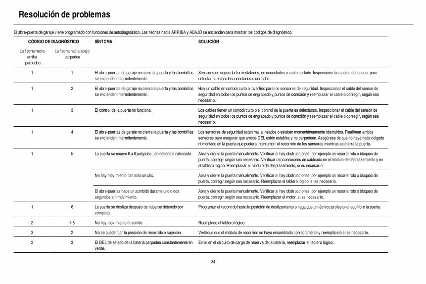
34
El abre-puerta de garaje viene programado con funciones de autodiagnóstico. Las flechas hacia ARRIBA y ABAJO se encienden para mostrar los códigos de diagnóstico.
CÓDIGO DE DIAGNÓSTICO SÍNTOMA SOLUCIÓN
La flecha haciaarribaparpadea
La flecha hacia abajoparpadea
1 1 El abre-puertas de garaje no cierra la puerta y las bombillasse encienden intermitentemente.
Sensores de seguridad no instalados, no conectados o cable cortado. Inspeccione los cables del sensor paradetectar si están desconectados o cortados.
1 2 El abre-puertas de garaje no cierra la puerta y las bombillasse encienden intermitentemente.
Hay un cable en cortocircuito o invertido para los sensores de seguridad. Inspeccionar el cable del sensor deseguridad en todos los puntos de engrapado y puntos de conexión y reemplazar el cable o corregir, según seanecesario.
1 3 El control de la puerta no funciona. Los cables tienen un cortocircuito o el control de la puerta es defectuoso. Inspeccionar el cable del sensor deseguridad en todos los puntos de engrapado y puntos de conexión y reemplazar el cable o corregir, según seanecesario.
1 4 El abre-puertas de garaje no cierra la puerta y las bombillasse encienden intermitentemente.
Los sensores de seguridad están mal alineados o estaban momentáneamente obstruidos. Realinear ambossensores para asegurar que ambos DEL estén estables y no parpadeen. Asegúrese de que no haya nada colgadoni montado en la puerta que pudiera interrumpir el recorrido de los sensores mientras se cierra la puerta.
1 5 La puerta se mueve 6 a 8 pulgadas , se detiene o retrocede. Abra y cierre la puerta manualmente. Verificar si hay obstrucciones, por ejemplo un resorte roto o bloqueo depuerta, corregir según sea necesario. Verificar las conexiones de cableado en el módulo de desplazamiento y enel tablero lógico. Reemplazar el módulo de desplazamiento, si es necesario.
No hay movimiento, tan solo un clic. Abra y cierre la puerta manualmente. Verificar si hay obstrucciones, por ejemplo un resorte roto o bloqueo depuerta, corregir según sea necesario. Reemplazar el tablero lógico, si es necesario.
El abre-puertas hace un zumbido durante uno o dossegundos sin movimiento.
Abra y cierre la puerta manualmente. Verificar si hay obstrucciones, por ejemplo un resorte roto o bloqueo depuerta, corregir según sea necesario. Reemplazar el motor, si es necesario.
1 6 La puerta se desliza después de haberse detenido porcompleto.
Programar el recorrido hasta la posición de deslizamiento o haga que un técnico profesional equilibre la puerta.
2 1-5 No hay movimiento ni sonido. Reemplace el tablero lógico.
3 2 No se puede fijar la posición de recorrido o sujeción. Verifique que el módulo de recorrido se haya ensamblado correctamente y reemplácelo si es necesario.
3 3 El DEL de estado de la batería parpadea constantemente enverde.
Error en el circuito de carga de reserva de la batería, reemplazar el tablero lógico.
Resolución de problemas
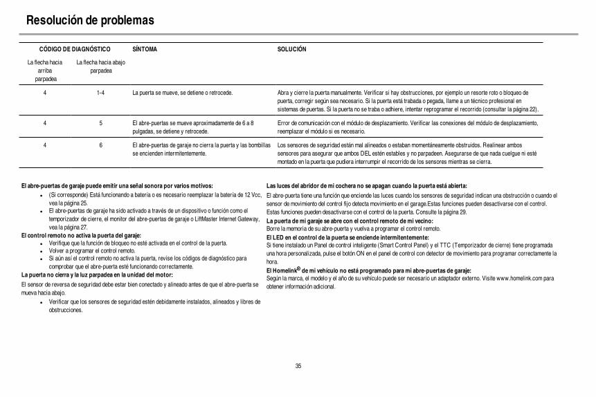
35
CÓDIGO DE DIAGNÓSTICO SÍNTOMA SOLUCIÓN
La flecha haciaarribaparpadea
La flecha hacia abajoparpadea
4 1-4 La puerta se mueve, se detiene o retrocede. Abra y cierre la puerta manualmente. Verificar si hay obstrucciones, por ejemplo un resorte roto o bloqueo depuerta, corregir según sea necesario. Si la puerta está trabada o pegada, llame a un técnico profesional ensistemas de puertas. Si la puerta no se traba o adhiere, intentar reprogramar el recorrido (consultar la página 22).
4 5 El abre-puertas se mueve aproximadamente de 6 a 8pulgadas, se detiene y retrocede.
Error de comunicación con el módulo de desplazamiento. Verificar las conexiones del módulo de desplazamiento,reemplazar el módulo si es necesario.
4 6 El abre-puertas de garaje no cierra la puerta y las bombillasse encienden intermitentemente.
Los sensores de seguridad están mal alineados o estaban momentáneamente obstruidos. Realinear ambossensores para asegurar que ambos DEL estén estables y no parpadeen. Asegurarse de que nada cuelgue ni estémontado en la puerta que pudiera interrumpir el recorrido de los sensores mientras se cierra.
El abre-puertas de garaje puede emitir una señal sonora por varios motivos:l (Si corresponde) Está funcionando a batería o es necesario reemplazar la batería de 12 Vcc,
vea la página 25.l El abre-puertas de garaje ha sido activado a través de un dispositivo o función como el
temporizador de cierre, el monitor del abre-puertas de garaje o LiftMaster Internet Gateway,vea la página 27.
El control remoto no activa la puerta del garaje:l Verifique que la función de bloqueo no esté activada en el control de la puerta.l Volver a programar el control remoto.l Si aún así el control remoto no activa la puerta, revise los códigos de diagnóstico para
comprobar que el abre-puerta esté funcionando correctamente.La puerta no cierra y la luz parpadea en la unidad del motor:
El sensor de reversa de seguridad debe estar bien conectado y alineado antes de que el abre-puerta semueva hacia abajo.
l Verificar que los sensores de seguridad estén debidamente instalados, alineados y libres deobstrucciones.
Las luces del abridor de mi cochera no se apagan cuando la puerta está abierta:
El abre-puerta tiene una función que enciende las luces cuando los sensores de seguridad indican una obstrucción o cuando elsensor de movimiento del control fijo detecta movimiento en el garage.Estas funciones pueden desactivarse con el control.Estas funciones pueden desactivarse con el control de la puerta. Consulte la página 29.La puerta de mi garaje se abre con el control remoto de mi vecino:Borre la memoria de su abre-puerta y vuelva a programar el control remoto.El LED en el control de la puerta se enciende intermitentemente:Si tiene instalado un Panel de control inteligente (Smart Control Panel) y el TTC (Temporizador de cierre) tiene programadauna hora personalizada, pulse el botón ON en el panel de control con detector de movimiento para programar correctamente lahora.El Homelink® de mi vehículo no está programado para mi abre-puertas de garaje:Según la marca, el modelo y el año de su vehículo puede ser necesario un adaptador externo. Visite www.homelink.com paraobtener información adicional.
Resolución de problemas

36
485LM Baterías de sistema de respaldo de 12 V:Proporcina energiá respaldo al abre-puertas de garaje.
886LMK Panel de control con la capacidad de detectar moviemiento:La unidad de control de funciones múltiples de la puerta está equipada con sensores de movimiento que mantendrán la luz encendida cada vez que alguien entre al garaje. Compatible con Security+ 2.0®.
Accessorios893MAX-LMK1 Control remoto MAX de 3
botones:Compatible con abre-puertas de garaje LiftMaster® fabricados desde 1993. Incluye broche para visera de vehículo.

37
GarantíaGARANTÍA LIMITADA DE UN AÑO DE MERIK
GARANTÍA LIMITADA DE POR VIDA DEL MOTORGARANTÍA LIMITADA DE UN AÑO POR LA SISTEMA DE BATERÍA DE RESERVA*
Merik (el “Vendedor”) garantiza al comprador original de este producto, en el lugar adonde fue instalado por primera vez, que el mismo está libre de defectos de materiales y/o de fabricación por un período de un año a partir de la fecha de compra, a excepción del motor, que están garantizados por defectos de materiales y/o fabricación por su vida útil en servicio en la residencia del usuario, y de la sistema de batería de reserva* que está garantizada por defectos de materiales y/o fabricación por un período de un año a partir de la fecha de compra. La operación correcta de éste producto depende de su acatamiento con las Instrucciones del Manual del Propietario referentes a la instalación, operación, mantenimiento y prueba. No cumplir estrictamente estas instrucciones, anulará por completo esta garantía limitada.
Si, durante el período de garantía limitada, parece que este producto contiene un defecto cubierto por esta garantía limitada, comuníquese al número de teléfono de servicio o el distributor de servicio en su lugar, antes de desmontar el producto. Cuando llame, recibirá instrucciones sobre el desarme y el envío del producto. A continuación, envié éste producto, una vez que sea pagado por anticipado y asegurado, al centro de servicio correspondiente, con el fi n de realizar la reparación, cubierta por la garantía. Por favor, incluir una descripción breve del problema y un recibo fechado como prueba de compra, con cualquier producto que sea devuelto por concepto de reparación cubierta por la garantía. Los productos devueltos al Vendedor para la reparación cubierta por la garantía, los cuales una vez recibidos por el Vendedor, se confi rme que sean defectuosos y que estén cubiertos por ésta garantía limitada, serán reparados o reemplazados (a opción únicadel Vendedor) sin costo para usted y serán devueltos con el porte pagado. Los componentes defectuosos serán reparados o reemplazados a opción única del Vendedor con componentes nuevos o reconstruidos de fábrica. [Usted tiene la responsabilidad de afrontar todo costo involucrado con el desmontaje y la instalación del producto o componente .]
TODO TIPO DE GARANTÍA IMPLÍCITA, INCLUYENDO GARANTÍA IMPLÍCITA DE APTITUD COMERCIAL O APTITUD PARA UN PROPÓSITO PARTICULAR ESTÁ LIMITADA A LA DURACIÓN DE LA GARANTÍA DECLARADA ANTERIORMENTE PARA LOS COMPONENTES CORRESPONDIENTES. Algunos estados no permiten la exclusión o limitación de daños consecuenciales, incidentales o especiales, de manera que la anterior limitación o exclusión puede ser que no se aplique a usted. ESTA GARANTIA LIMITADA NO CUBRE DAÑO ALGUNO QUE SURJA COMO CONSECUENCIA NO RELACIONADA CON DEFECTO ALGUNO DEL PRODUCTO, NI TAMPOCO CUBRE EL DAÑO CAUSADO POR LA INCORRECTA INSTALACION, OPERACION O CUIDADO (INCLUYENDO PERO NO LIMITADA AL ABUSO, MALTRATO, FALTA DE PROPORCIONAR EL MANTENIMIENTO RAZONABLE Y NECESARIO, O CUALQUIER ALTERACION A ESTE PRODUCTO), NI LOS CARGOS DE MANO DE OBRA PARA DESMANTELAR O VOLVER A INSTALAR UNA UNIDAD REPARADA O REEMPLAZADA, NI TAMPOCO EL REEMPLAZO DE LAS BATERIAS. ESTA GARANTÍA LIMITADA NO CUBRE PROBLEMAS RELACIONADOS DIRECTAMENTE CON LA PUERTA NI CON LOS ACCESORIOS DE LA MISMA, INCLUYENDO RESORTES, RODILLOS, BISAGRAS NI OTROS PROBLEMAS DE ALINEACIÓN. ESTA GARANTÍA LIMITADA TAMPOCO CUBRE PROBLEMAS CAUSADOS POR INTERFERENCIA ELECTRÓNICA. BAJO NINGUNA CIRCUNSTANCIA EL VENDEDOR SERA RESPONSABLE DE DAÑOS CONSECUENCIALES, INCIDENTALES O ESPECIALES QUE SURJAN EN RELACION CON EL USO O INCAPACIDAD DE USO DE ESTE PRODUCTO. LA RESPONSABILIDAD DEL VENDEDOR POR VIOLACION DE LA GARANTIA, POR VIOLACION DEL CONTRATO, NEGLIGENCIA O RESPONSABILIDAD ESTRICTA, EN NINGUN CASO DEBERA EXCEDER AL COSTO DEL PRODUCTO CUBIERTO POR LA PRESENTE. NINGUNA PERSONA ESTA AUTORIZADA A ASUMIR POR NOSOTROS NINGUNA RESPONSABILIDAD POR LA VENTA DE ESTE PRODUCTO.
Algunos estados no permiten la exclusión o limitación de daños consecuenciales, incidentales o especiales, de manera que la anterior limitación o exclusión puede ser que no se aplique a usted. Esta garantía limitada le proporciona derechos legales específi cos y usted puede también tener otros derechos los cuales varían de un estado a otro.
*Si corresponde.
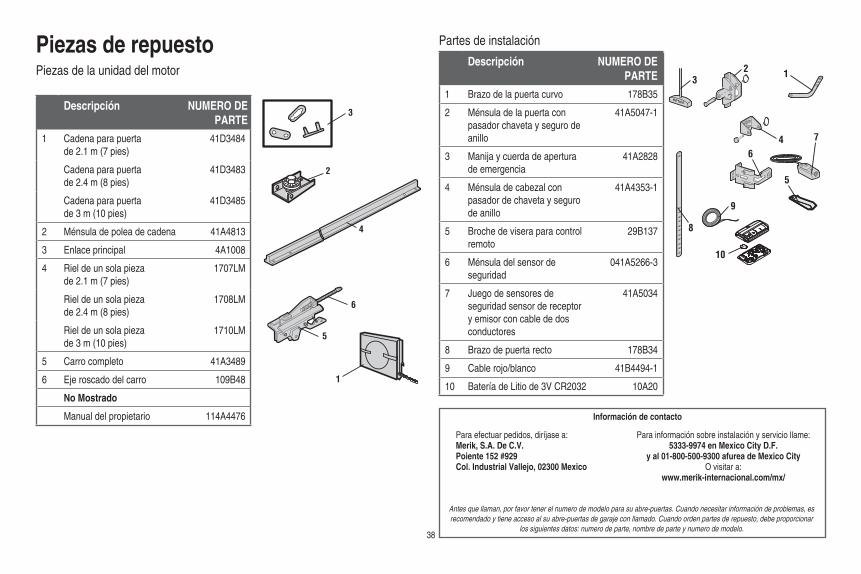
38
Piezas de repuestoPiezas de la unidad del motor
Partes de instalación
1
3
4
5
6
2
NOTICE
UPCEILING MOUNT ONLY
123
4
5
6
7
8
9
10
Descripción NUMERO DEPARTE
1 Cadena para puerta de 2.1 m (7 pies)
41D3484
Cadena para puerta de 2.4 m (8 pies)
41D3483
Cadena para puerta de 3 m (10 pies)
41D3485
2 Ménsula de polea de cadena 41A4813
3 Enlace principal 4A1008
4 Riel de un sola pieza de 2.1 m (7 pies)
1707LM
Riel de un sola pieza de 2.4 m (8 pies)
1708LM
Riel de un sola pieza de 3 m (10 pies)
1710LM
5 Carro completo 41A3489
6 Eje roscado del carro 109B48
No Mostrado
Manual del propietario 114A4476
Descripción NUMERO DEPARTE
1 Brazo de la puerta curvo 178B35
2 Ménsula de la puerta con pasador chaveta y seguro de anillo
41A5047-1
3 Manija y cuerda de apertura de emergencia
41A2828
4 Ménsula de cabezal con pasador de chaveta y seguro de anillo
41A4353-1
5 Broche de visera para control remoto
29B137
6 Ménsula del sensor de seguridad
041A5266-3
7 Juego de sensores de seguridad sensor de receptor y emisor con cable de dos conductores
41A5034
8 Brazo de puerta recto 178B34
9 Cable rojo/blanco 41B4494-1
10 Batería de Litio de 3V CR2032 10A20
Información de contacto
Antes que llaman, por favor tener el numero de modelo para su abre-puertas. Cuando necesitar información de problemas, es recomendado y tiene acceso al su abre-puertas de garaje con llamado. Cuando orden partes de repuesto, debe proporcionar
los siguientes datos: numero de parte, nombre de parte y numero de modelo.
Para efectuar pedidos, diríjase a:Merik, S.A. De C.V.Poiente 152 #929Col. Industrial Vallejo, 02300 Mexico
Para información sobre instalación y servicio llame:5333-9974 en Mexico City D.F.
y al 01-800-500-9300 afurea de Mexico CityO visitar a:
www.merik-internacional.com/mx/

© 2015, The Chamberlain Group, Inc.114A4476E Todos los derechos reservados
11
12b12a
4
10
1
95
3
6
2
78
4 3
Piezas de repuestoPiezas de abre-puertas de garaje
Descripción NUMERO DEPARTE
1 Correa casquillo y piñón 41B5348-2
2 Panel de extremo con puerta de batería y casquillo de la luz
41D217
3 Lente 41A7562
4 Receptáculo de foco 41C279
5 Transformador 41A7635
6 Cubierta 41A7619-8
7 Motor y módulo de recorrido 41D1739-1
8 Módulo de viaje 41A7114-7
9 Panel de extremo con casquillo de la luz 41D216
10 Tabla de lógico de receptor 45DCT
11 Cordón eléctrico
Modelos fabrica antes de Octubre 2012 41B135-1
Modelos fabrica después de Octubre 2012 41B4245
12a Tabla de fi ltro con tornillos (models fabrica antes de Octubre 2012)
41B7611
12b Terminal bloquear (models fabrica después de Octubre 2012)
41A3150
No Mostrado
Arnés con tornillos (modelos fabrica antes de Octubre 2012)
41B7418
Arnés con tornillos (modelos fabrica después de Octubre 2012)
41B7610-1