Embed Size (px)
Citation preview

11-1 CivilFEM Workbook. Ingeciber, S.A.©
Ver. 14.5
11. Push-over analysis
Applicable CivilFEM Product: All CivilFEM Products
Level of Difficulty: Moderate
Interactive Time Required: 90 minutes
Discipline: Structural Steel
Analysis Type: Push Over
Element Type Used: Shell 181 and Surf 154
Active Code: Eurocodes 3 and 8
Units System: N, m, s
CivilFEM Features Demonstrated: Units selection, code selection, material definition, shell definition, push-over analysis.
Problem Description
Given
The problem consists of an analysis of push over applied to a tank which contains water.
Geometry: Height= 25 m
Diameter= 12 m

11-2 CivilFEM Workbook. Ingeciber, S.A.©
Ver. 14.5
Push-Over pressures Water pressures
P_BOT= ρ·g·h
Material: Fe 360
Element type: Shell 181
Surf 154
Pressures: Push-Over Pressures: Gradient pressure with slope= 40
Watt: Gradient pressure with slope= P_BOT/ H_CYL
(H_CYL= 25 m)
Approach and Assumptions
This is a push-over analysis with 3D elastic elements and elastic material properties. Model geometry is defined with nodes and elements.
Summary of Steps
Preprocessing
1. Preprocessing
2. Specify title
3. Set code
4. Set units
5. Define parameters

11-3 CivilFEM Workbook. Ingeciber, S.A.©
Ver. 14.5
6. Define materials
7. Define element type
8. Define Shell properties
9. Define Geometry
10. Save the database
Solution
11. Apply displacement constrain
12. ¡Error! No se encuentra el origen de la referencia.s
13. Push-Over Analysis
Interactive Step-by-Step Solution
1. Preprocessing
A typical CivilFEM analysis begins with providing data such as the units system, active code, materials, element types, section and model geometry definition.
2. Specify title
Although this step is not required for a CivilFEM analysis, we recommend that you make it part of all your analysis.
Utility Menu: File Change title
Enter the title: Push-over analysis.
OK to define the title and close the dialog box.
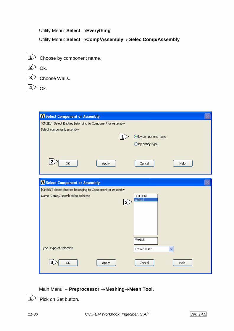
1
2
1
2
11-4 CivilFEM Workbook. Ingeciber, S.A.©
Ver. 14.5
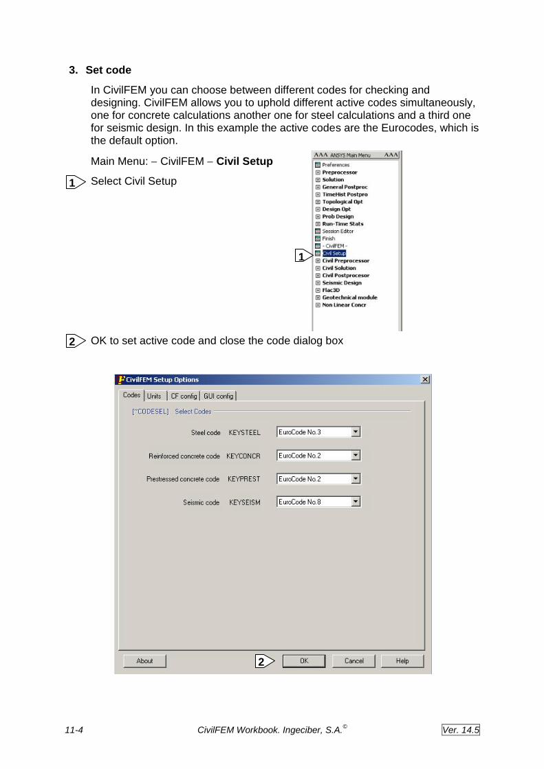
3. Set code
In CivilFEM you can choose between different codes for checking and designing. CivilFEM allows you to uphold different active codes simultaneously, one for concrete calculations another one for steel calculations and a third one for seismic design. In this example the active codes are the Eurocodes, which is the default option.
Main Menu: CivilFEM Civil Setup
Select Civil Setup
OK to set active code and close the code dialog box
1
2
2
1

11-5 CivilFEM Workbook. Ingeciber, S.A.©
Ver. 14.5
4. Set units
In CivilFEM you must define a unit system. CivilFEM will need such a system to perform calculations according to Code. You should maintain it during the entire design. In this analysis, we will select the International System units, that is, meters, seconds and Newtons.
Main Menu: CivilFEM Civil Setup
Choose Units Library
OK to accept units and close the units dialog box
1
2
2

11-6 CivilFEM Workbook. Ingeciber, S.A.©
Ver. 14.5
5. Define parameters:
PII=3.1416
D_CYL= 12 Diameter
H_CYL= 25 High
H_WAT= H_CYL
TH_BOT= 10E-3
TH_TOP= 35E-3
P_TOP= 0
P_BOT= 1000*9.8*H_WAT
SLOPE = (P_TOP - P_BOT)/H_CYL
V2= PII*(H_WAT-TH_BOT)*(D_CYL**2-(D_CYL-TH_TOP)**2)/4
Mw = 2175613.
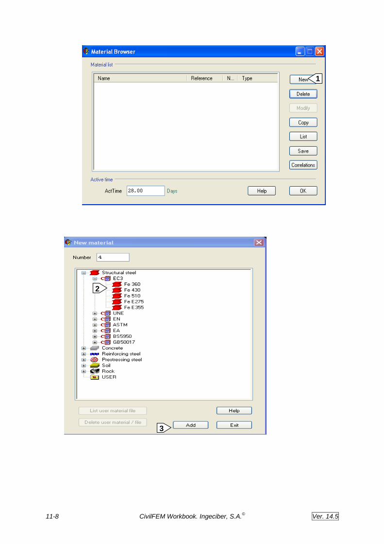
6. Define materials
Material properties definition is performed with the CivilFEM ~CFMP command. This command automatically defines the ANSYS material properties (density, Young’s modulus, Poisson’s ratio and thermal expansion coefficient) and the CivilFEM material properties necessary for code checking. In this case we will select Fe 360 steel.
The CivilFEM ~CFMP command allows us to define stress-strain diagrams, to define safety coefficients, to control the linear or non-linear behavior of the material and to select the activation time of the material.
Main Menu: CivilFEM Civil Preprocessor Materials
Pick new to define a new material
Choose Fe 360 Steel and all the material properties corresponding to Fe360 steel are automatically calculated according to Eurocode 3 (active code)
The Add button must be clicked 2 times to define the materials:
1. Fe 360 for the bottom of the tank.
2. Fe 360 material which density is going to be modified to bear the weight of the water in mind.
Density= 7850+(Mw/V2)
3. Material 3 with void density for SURF 154 element. Command MP
Modify for material 2. 4
1
3
2

11-7 CivilFEM Workbook. Ingeciber, S.A.©
Ver. 14.5
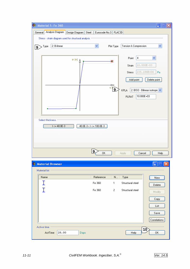
Write +(Mw)/V2 for density.
Choose bi-linear for type of Analysis Diagram. (It is necessary that the type of graph is changed of linearly to bilinear for the type of analysis that is going to be realized).
Choose Biso for plasticity key.
Ok
Modify material 1. Choose bi-linear for type or Analysis Diagram and Biso for plasticity key for the material
Ok.
Write MP,DENS,3,0
11
10
9
8
7
6
5
11-8 CivilFEM Workbook. Ingeciber, S.A.©
Ver. 14.5
1
3
2

11-9 CivilFEM Workbook. Ingeciber, S.A.©
Ver. 14.5
5
4

11-10 CivilFEM Workbook. Ingeciber, S.A.©
Ver. 14.5
9
6
8
7
11-11 CivilFEM Workbook. Ingeciber, S.A.©
Ver. 14.5
10
9
9
9

11-12 CivilFEM Workbook. Ingeciber, S.A.©
Ver. 14.5
7. Define element type
Checking and designing according to codes is only performed on CivilFEM supported element types, although you can use any ANSYS element to define your model, only the CivilFEM supported elements will be checked according to codes. In the element type menu you can see the CivilFEM supported beam elements.
We will use Shell 181 and Surf 154
Main Menu: CivilFEM Civil Preprocess Element Types Other
ElementsAdd/ Edit/ Delete.
Add.
Choose Shell181 and Apply.
Choose Surface Effect 154 and Ok.
Click on Options for Surf 154.
Choose exclude for midside nodes and Full Area w/tan for Pres vector orientation.
Ok.
Close.
1
7
6
5
4
3
11
1
2
2

11-13 CivilFEM Workbook. Ingeciber, S.A.©
Ver. 14.5
4
3
2

11-14 CivilFEM Workbook. Ingeciber, S.A.©
Ver. 14.5
8. Define Shell Properties
Main Menu: CivilFEM Civil Preprocess Shell Vertex
7
5
5
6

11-15 CivilFEM Workbook. Ingeciber, S.A.©
Ver. 14.5
Choose Steel.
Write TH_BOT for thickness.
Choose material 1
Ok.
1
4
3
2
1

11-16 CivilFEM Workbook. Ingeciber, S.A.©
Ver. 14.5
Main Menu: CivilFEM Civil Preprocess Shell Vertex
Choose Steel.
Write TH_TOP for thickness.
Choose material 2
Ok.
Exit.
5
4
3
2
1
2
3
4

11-17 CivilFEM Workbook. Ingeciber, S.A.©
Ver. 14.5
4
3
2
2 2
3
4
1

11-18 CivilFEM Workbook. Ingeciber, S.A.©
Ver. 14.5
Main Menu: CivilFEM Civil Preprocess Beam & Shell Properties.
CivilFEM command ~BMSHPRO will be used to define ANSYS real constants.
Choose New Shell.
Choose SHELL 181 for Ename
Choose vertex 1
Apply.
Choose vertex 2
Ok.
Exit. 7
6
5
4
3
2
1
5

11-19 CivilFEM Workbook. Ingeciber, S.A.©
Ver. 14.5
2 4
3
1

11-20 CivilFEM Workbook. Ingeciber, S.A.©
Ver. 14.5
7
5
6
7

11-21 CivilFEM Workbook. Ingeciber, S.A.©
Ver. 14.5
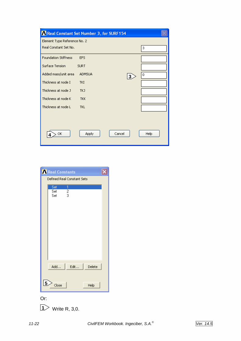
9. Define real constant for surf element
Main Menu: Preprocessor Real Constants Add/Edit/Delete.
Add.
Choose Surf 154 and Ok.
Write 0 for Added mass/unit area.
Ok.
Close.
2
1
5
4
3
2
1
11-22 CivilFEM Workbook. Ingeciber, S.A.©
Ver. 14.5
Or:
Write R, 3,0. 1
5
3
4

11-23 CivilFEM Workbook. Ingeciber, S.A.©
Ver. 14.5
10. Define Geometry
Main Menu: Preprocessor ModelingCreateVolumesCylinder Hollow Cylinder.
Write D_CYL/2 for Rad-1 and H_CYL for Depth.
Ok.
Main Menu: Preprocessor ModelingDeleteVolumes Only.
Pick All.
Ok. 2
1
2
1
2
1
1
3

11-24 CivilFEM Workbook. Ingeciber, S.A.©
Ver. 14.5
Utility Menu: Select Entities
Choose Areas By Location.
Choose Z coordinates.
Write H_CYL for Min,Max.
Ok.
Main Menu: Preprocessor ModelingDeleteAreas Only.
Pick All. 1
4
3
2
1
1
2
1
2
3
4

11-25 CivilFEM Workbook. Ingeciber, S.A.©
Ver. 14.5
Ok.
Utility Menu: Select Everything
Main Menu: Preprocessor Numering CtrlsCompress Numbers.
Choose Areas.
Ok.
Utility Menu: Select Entities
Choose Areas By Num Pick. 1
1
2
2
1
2
2
2
1

11-26 CivilFEM Workbook. Ingeciber, S.A.©
Ver. 14.5
Ok.
Write 2, 3.
Ok.
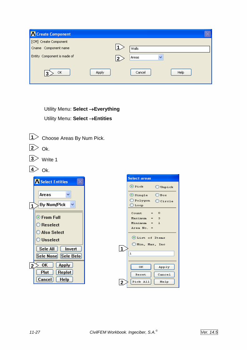
Utility Menu: Select Comp/ AssemblyCreate Component
Write Walls for component name.
Choose Areas.
Ok.
3
2
1
4
3
2
1
4
3
2
11-27 CivilFEM Workbook. Ingeciber, S.A.©
Ver. 14.5
Utility Menu: Select Everything
Utility Menu: Select Entities
Choose Areas By Num Pick.
Ok.
Write 1
Ok.
1
2
4
3
2
1
3
2
1
1
2

11-28 CivilFEM Workbook. Ingeciber, S.A.©
Ver. 14.5
Utility Menu: Select Comp/ AssemblyCreate Component
Write Bottom for component name.
Choose Areas.
Ok.
Utility Menu: Select Everything
( A regular mesh is obtained after the lines are concatenated).
Utility Menu: Select Entities
Select Lines by Location with z=0. (From full)
Ok.
. Utility Menu: Select Entities
Select Lines by Location with y=0, 6. (Reselect)
Ok.
MainMenu:PreprocessorMeshingMeshAreasMapped
ConcatenateLines
Pick All.
Ok.
Commands:
LSEL,S,LOC,Z,0 (Select lines, from full, by location, z= 0)
LPLOT ( Plot lines)
LSEL,R,LOC,Y,0,6 (Select lines, reselect, by location, Y=6)
6
5
4
3
2
1
3
2
1
3
2
1

11-29 CivilFEM Workbook. Ingeciber, S.A.©
Ver. 14.5
LPLOT
LCCAT,ALL ( Concatenate lines)
ALLSEL
Utility Menu: Select Everything
Concatenate the next lines in the same way.
Comands:
LSEL,S,LOC,Z,0
5
6
1
2
3
3

11-30 CivilFEM Workbook. Ingeciber, S.A.©
Ver. 14.5
LPLOT
LSEL,R,LOC,Y,0,-6
LPLOT
LCCAT,ALL
ALLSEL
LSEL,S,LOC,Z,25
LPLOT
LSEL,R,LOC,Y,0,6
LPLOT
LCCAT,ALL
ALLSEL
LSEL,S,LOC,Z,25
LPLOT
LSEL,R,LOC,Y,0,-6
LPLOT
LCCAT,ALL
ALLSEL
Utility Menu: Select Everything
Utility Menu: Select Comp/AssemblySelec Comp/Assembly
Choose by component name.
Ok.
Choose Bottom.
Ok.
4
3
2
1

11-31 CivilFEM Workbook. Ingeciber, S.A.©
Ver. 14.5
Main Menu: Preprocessor MeshingMesh Tool.
Pick on Set button.
Choose Shell 181 , mat 1 and Section Number 1.
Ok.
Choose Areas and Free Tri mesh.
Click on Mesh buttom.
Pick All and Ok.
6
5
4
3
2
1
3
4
1
2

11-32 CivilFEM Workbook. Ingeciber, S.A.©
Ver. 14.5
16
6
5
4
11-33 CivilFEM Workbook. Ingeciber, S.A.©
Ver. 14.5
Utility Menu: Select Everything
Utility Menu: Select Comp/AssemblySelec Comp/Assembly
Choose by component name.
Ok.
Choose Walls.
Ok.
Main Menu: Preprocessor MeshingMesh Tool.
Pick on Set button. 1
36
46
1
2
4
3
2
1

11-34 CivilFEM Workbook. Ingeciber, S.A.©
Ver. 14.5
Choose Shell 181 , mat 2 and Section Number 2.
Ok.
Choose Areas and mapped cuad mesh.
Click on Mesh buttom.
PIck All.
2
3
16
5
4
6
5
4
3
2
11-35 CivilFEM Workbook. Ingeciber, S.A.©
Ver. 14.5
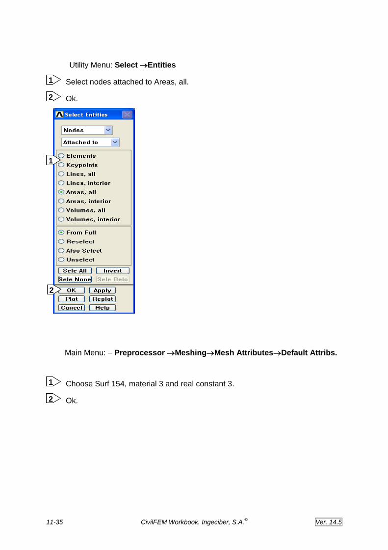
Utility Menu: Select Entities
Select nodes attached to Areas, all.
Ok.
Main Menu: Preprocessor MeshingMesh AttributesDefault Attribs.
Choose Surf 154, material 3 and real constant 3.
Ok.
2
1
1
2
2
1

11-36 CivilFEM Workbook. Ingeciber, S.A.©
Ver. 14.5
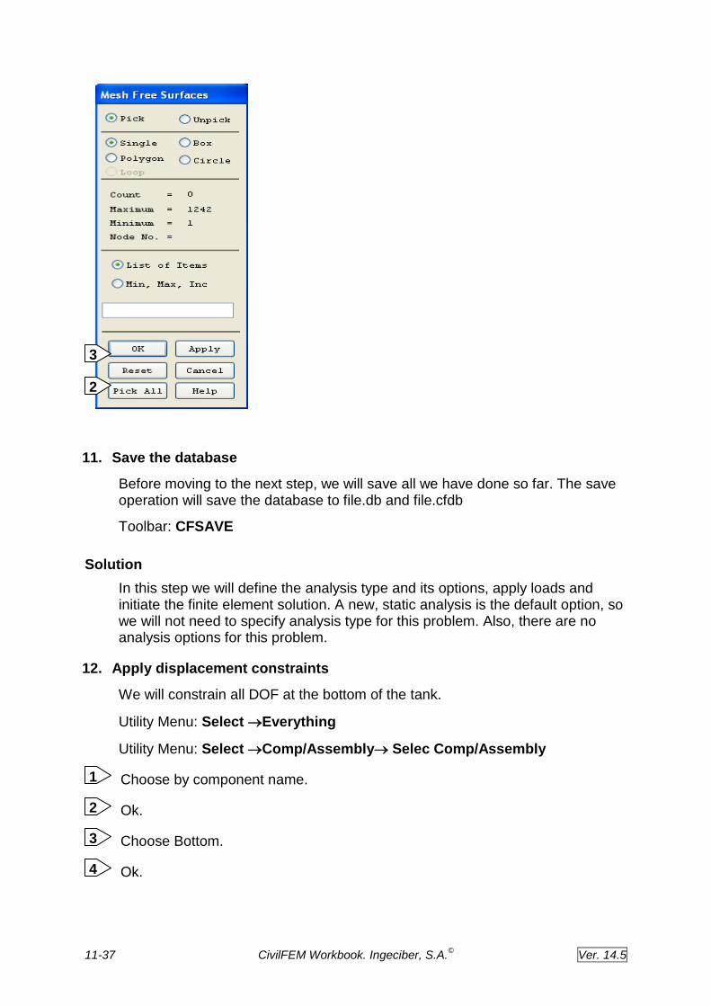
Main Menu: Preprocessor ModelingCreateElementsSurf
/ContactSurf to Surf.
Ok.
Pick All.
Ok.
1
3
2
1
2
1
11-37 CivilFEM Workbook. Ingeciber, S.A.©
Ver. 14.5
11. Save the database
Before moving to the next step, we will save all we have done so far. The save operation will save the database to file.db and file.cfdb
Toolbar: CFSAVE
Solution
In this step we will define the analysis type and its options, apply loads and initiate the finite element solution. A new, static analysis is the default option, so we will not need to specify analysis type for this problem. Also, there are no analysis options for this problem.
12. Apply displacement constraints
We will constrain all DOF at the bottom of the tank.
Utility Menu: Select Everything
Utility Menu: Select Comp/AssemblySelec Comp/Assembly
Choose by component name.
Ok.
Choose Bottom.
Ok.
4
3
2
1
3
2

11-38 CivilFEM Workbook. Ingeciber, S.A.©
Ver. 14.5
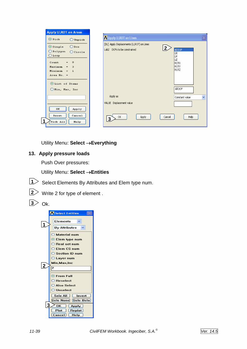
Main Menu: Solution Define Loads Apply Structural
Displacement On Areas
Pick All.
Choose All DOF to be constrained
Ok. 3
3
4
1
2
1
2
11-39 CivilFEM Workbook. Ingeciber, S.A.©
Ver. 14.5
Utility Menu: Select Everything
13. Apply pressure loads
Push Over pressures:
Utility Menu: Select Entities
Select Elements By Attributes and Elem type num.
Write 2 for type of element .
Ok.
1
2
3
3
2
1
2
3 1

11-40 CivilFEM Workbook. Ingeciber, S.A.©
Ver. 14.5
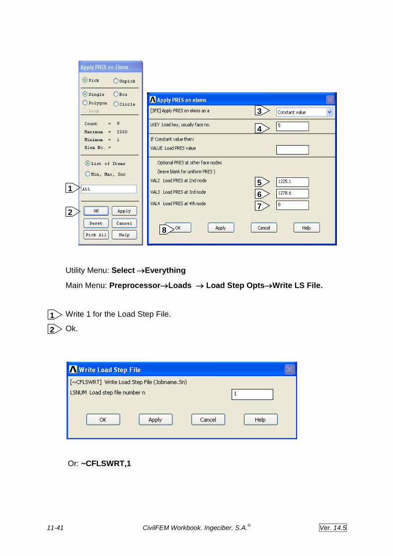
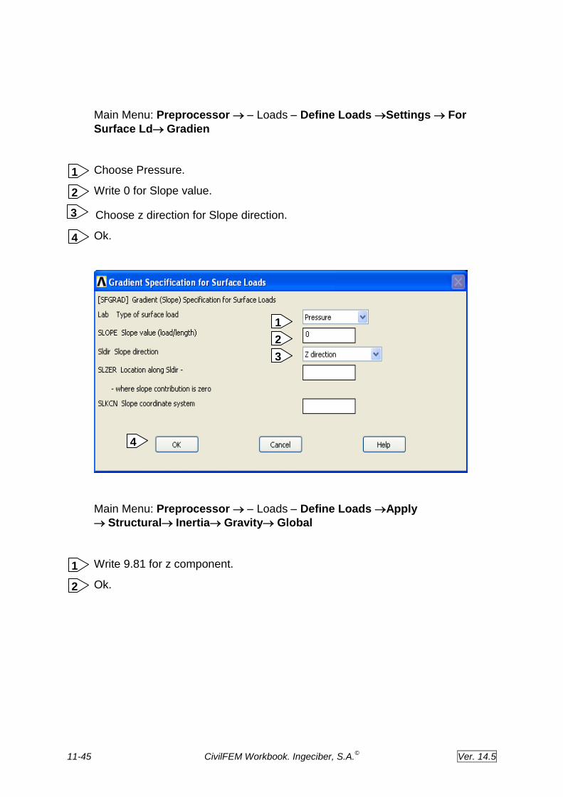
Main Menu: Preprocessor Loads Define Loads Settings For
Surface LdGradient
Choose Pressure.
Write 40 for Slope value.
Choose z direction for Slope direction.
Ok.
Main Menu: Preprocessor Loads Define Loads Apply
StructuralPresureOn Elements.
Write ALL.
Ok.
Choose Constant value.
Write 5 for LKEY.
Write 1225.1 for VAL2 .
Write 1278.6 for VAL3.
Write 0 for VAL4.
Ok.
1
2
3
4
3
1
2
3
4
7
5
6
8
1
2
4
11-41 CivilFEM Workbook. Ingeciber, S.A.©
Ver. 14.5
Utility Menu: Select Everything
Main Menu: PreprocessorLoads Load Step OptsWrite LS File.
Write 1 for the Load Step File.
Ok.
Or: ~CFLSWRT,1
6
5
4
3
7
8
1
2
1
2

11-42 CivilFEM Workbook. Ingeciber, S.A.©
Ver. 14.5
Main Menu: Preprocessor Loads Define Loads Settings For
Surface LdGradien
Choose Pressure.
Write 0 for Slope value.
Choose z direction for Slope direction.
Ok.
Other pressures:
Bottom pressures
(Select Bottom component)
Utility Menu: Select Entities
(Select elements attached to Areas)
Main Menu: Preprocessor Loads Define Loads Apply
StructuralPresureOn Elements.
Pick All.
Write P_BOT for load pres value.
Ok.
1
2
3
4
3
1
2
4
2
3
1

11-43 CivilFEM Workbook. Ingeciber, S.A.©
Ver. 14.5
Utility Menu: Select Everything
Walls pressures:
(Select Walls component)
Utility Menu: Select Entities
(Select elements attached to Areas)
Main Menu: Preprocessor Loads Define Loads Settings For
Surface LdGradien.
Choose Pressure.
Write SLOPE for Slope value.
Choose z direction for Slope direction.
Ok.
3
2
3 1
1
2
4

11-44 CivilFEM Workbook. Ingeciber, S.A.©
Ver. 14.5
Main Menu: Preprocessor Loads Define Loads Apply
StructuralPresureOn Elements.
Pick All.
Write P_TOP for load press value.
Ok.
3
2
1
3
3
2
1
4
1
2
11-45 CivilFEM Workbook. Ingeciber, S.A.©
Ver. 14.5
Main Menu: Preprocessor Loads Define Loads Settings For
Surface LdGradien
Choose Pressure.
Write 0 for Slope value.
Choose z direction for Slope direction.
Ok.
Main Menu: Preprocessor Loads Define Loads Apply
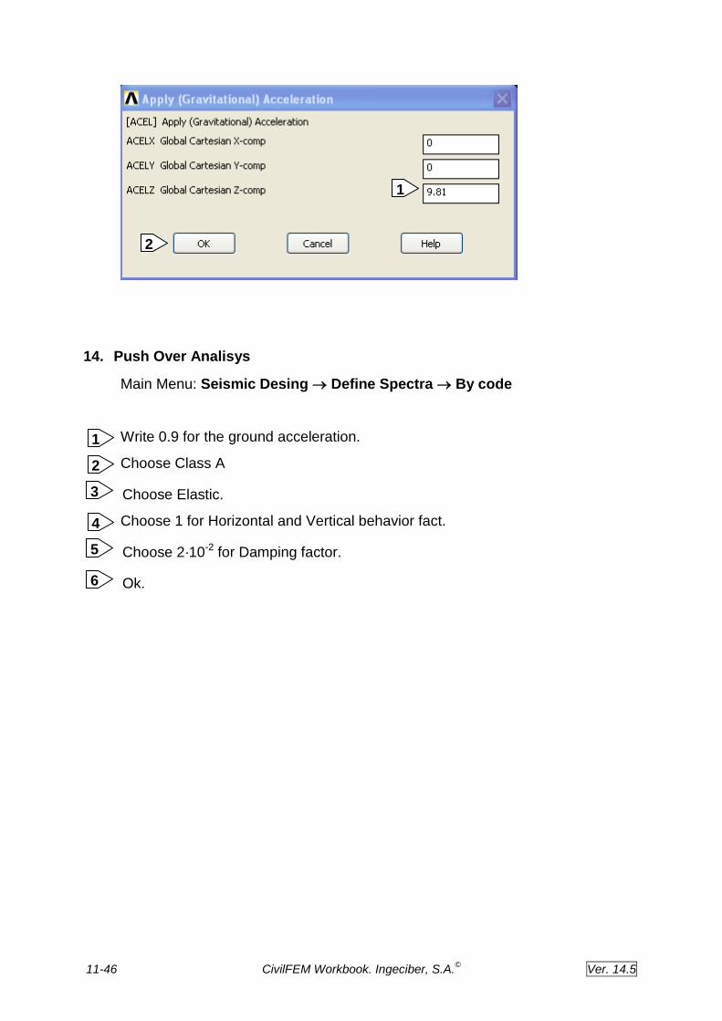
StructuralInertiaGravityGlobal
Write 9.81 for z component.
Ok.
1
2
3
4
3
1
2
4
1
2
11-46 CivilFEM Workbook. Ingeciber, S.A.©
Ver. 14.5
14. Push Over Analisys
Main Menu: Seismic Desing Define Spectra By code
Write 0.9 for the ground acceleration.
Choose Class A
Choose Elastic.
Choose 1 for Horizontal and Vertical behavior fact.
Choose 2·10-2 for Damping factor.
Ok.
6
5
3
2
1
1
2
4

11-47 CivilFEM Workbook. Ingeciber, S.A.©
Ver. 14.5
Main Menu: Seismic Desing Modal Solution.
Write 50 for Number of modes to be extracted.
Choose Block Lanczos as the Extraction Method.
Ok.
1
2
3
3
1
2
3
6
5
4
3
4
5
1
2
11-48 CivilFEM Workbook. Ingeciber, S.A.©
Ver. 14.5
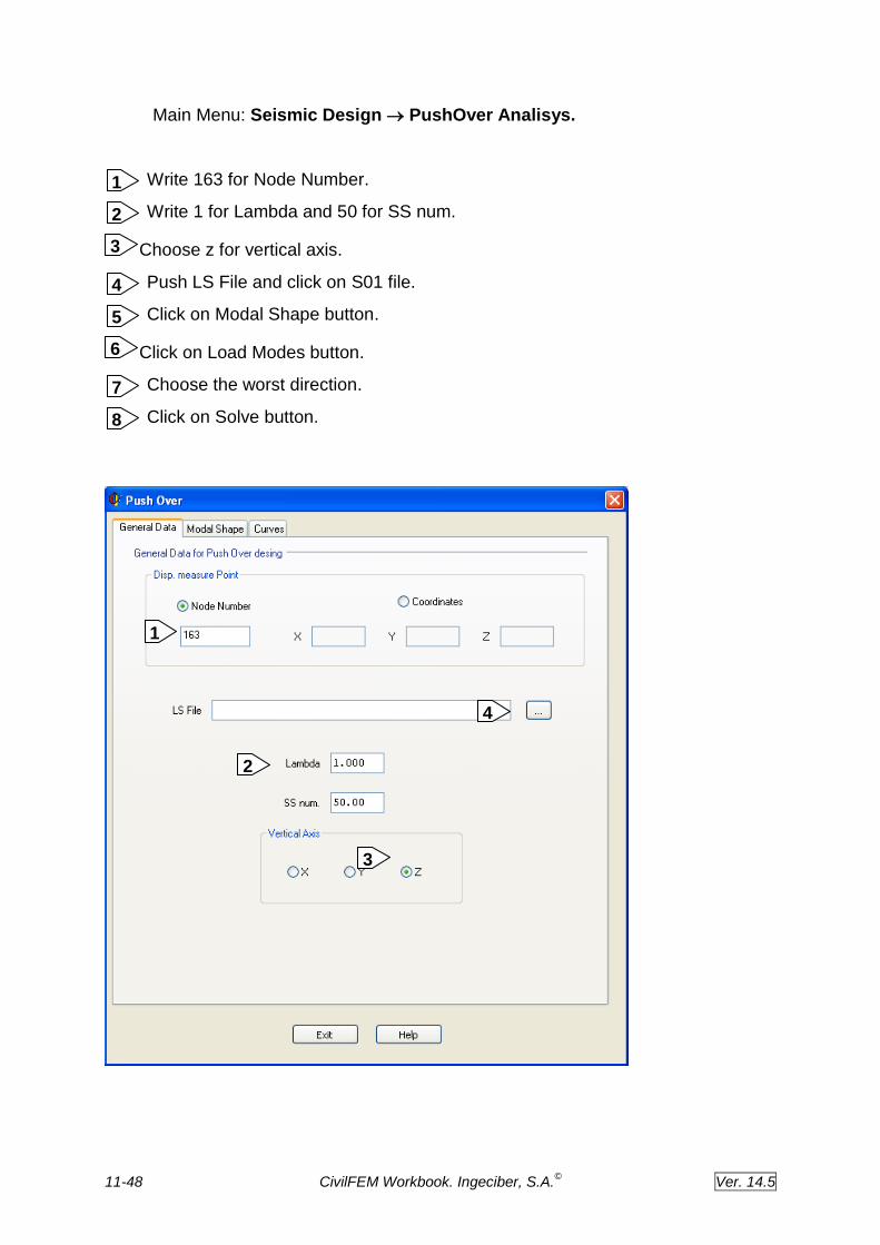
Main Menu: Seismic Design PushOver Analisys.
Write 163 for Node Number.
Write 1 for Lambda and 50 for SS num.
Choose z for vertical axis.
Push LS File and click on S01 file.
Click on Modal Shape button.
Click on Load Modes button.
Choose the worst direction.
Click on Solve button.
6
3
1
2
4
5
7
8
1
2
4
3

11-49 CivilFEM Workbook. Ingeciber, S.A.©
Ver. 14.5
5

11-50 CivilFEM Workbook. Ingeciber, S.A.©
Ver. 14.5
7
8
6

11-51 CivilFEM Workbook. Ingeciber, S.A.©
Ver. 14.5
ESEL,U,TYPE,,2 to view shell elements without the surf elements.
~RETROFT,LAMBDA,1