Embed Size (px)
Citation preview

PUSH OVER ANALYSIS FOR RC BUILDING
WITH AND WITHOUT FLOATING COLUMNS
Stella evangeline 1, Student(m.tech) D.Satish 2, M.Tech (structures) E V Raghava Rao 3,
Civil engineering dept , Asst.professor, HOD of civil dept,
Visakha technical campus civil engineering dept, Visakha technical campus,
Visakhapatnam,,India Coastal institute of technology. [email protected].
Abstract— Rc structure and Floating column structure are typical
features in the modern multi-storey constructions in urban
India. Such features are highly undesirable in buildings
built in seismically active areas; this has been verified in
numerous experiences of strong shaking during the past
earthquakes like Bhuj 2001. In this study an attempt is made
to reveal the effects of floating column & rc building effected
with sesmic forces. For this purpose Push over analysis is
adopted because this analysis will yield performance level of
building for design capacity (displacement) carried out up to
failure, it helps determination of collapse load and ductility
capacity of the structure. To achieve this objective, three RC
bare frame structures with G+4 stories will be analysed and
compared the base force and displacement of RC bare frame
structure for earthquake forces by varing column
dimensions using SAP 2000 14 analysis package.
Keywords— floating column, rc structure, pushover analysis, earthquake
forces.
1. INTRODUCTION
Many urban multistorey buildings in India today have
open first storey as an unavoidable feature. This is
primarily being adopted to accommodate parking or
reception lobbies in the first storey. Whereas the
totalseismic base shear as experienced by a building
during an earthquake is dependent on its natural period,
the seismic force distribution is dependent on the
distribution of stiffness and mass along the height. The
behavior of a building during earthquakes depends
critically on its overall shape, size and geometry, in
addition to how the earthquake forces are carried to the
ground.
2.1 FLOATING CLOUMNS
Floating column is also a vertical member, The Columns Float
or move in above stories such that to provide more open space
is known as Floating columns. Floating columns are
implemented, specially above the base floor, so that added
open space is accessible for assembly hall or parking purpose.
For the study of the floating column many projects have been
undertaken where the transfer of load is through the girders.
Floating columns are usually adopted above the ground storey
level. So that maximum space is made available in the ground
floor which is essentially required in apartments, mall or other
commercial buildings where parking is a major problem.
But those structures cannot be demolished; rather study can be
done to strengthen the structure. The stiffness of these
columns can be increased by retrofitting or these may be
provided by bracing to decrease the lateral deformation.
Many high rise buildings are planned and constructed with
architectural complexities. The complexities are nothing but
soft storey, floating column, heavy load, the reduction in
stiffness, etc.
3. METHODLOGY
In the of case structures to avoid earth quake damages, special
arrangement needs to be made to increase the lateral strength
and stiffness of the members. As per IS 1893 (part-1): 2002,
Dynamic analysis (Linear or Non-linear) of building is carried
out including the strength and stiffness effects and inelastic
deformations in the members and the members designed
accordingly. The lateral loads due to earthquake were
calculated using Response spectrum method as per IS 1893
(part-1): 2002. CALCULATION OF BASE SHEAR
The total design lateral force or design seismic base shear (VB)
is calculated according to clause 7.5.3 of IS 1893:2002 (IS
1893:2002 is referred to as the Code subsequently).
The total Base shear
International Journal of Advancements in Research & Technology, Volume 4, Issue 11, November -2015 ISSN 2278-7763
51
Copyright © 2015 SciResPub. IJOART
IJOART

Where A
h is the design horizontal seismic coefficient
Here
Z = Zone Factor
I = Importance Factor
R = Response Reduction Factor
The values of Z, I, R are given in Tables 2, 6, 7 respectively in
IS 1893 (part-1):2002.
Sa/g = Spectral acceleration coefficient. It is calculated
according to Clause 6.4.5 of the Code corresponding to the
fundamental time period Ta in seconds is given as follows.
For a Moment Resisting Frame without infill
For a Moment Resisting Frame with brick infill panels
Here
h = Height of the Building Frame
d = Base dimension of the building at the plinth level in
meters, along the considered direction of the lateral load s
PUSHOVER ANALYSIS
Pushover analysis is a static, nonlinear procedure in which the
magnitude of the lateral loads is incrementally increased,
maintaining a predefined distribution pattern along the height
of the building. Pushover analysis can determine the behaviour
of a building, including the ultimate load and the maximum
inelastic deflection. Local nonlinear effects are modelled and
the structure is pushed until a collapse mechanism is
developed. At each step, the base shear and the roof
displacement can be plotted to generate the pushover curve
NON-LINEAR STATIC ANALYSIS
The existing building can become seismically deficient since
seismic design code requirements are constantly upgraded and
advancement in engineering knowledge. Further, Indian
buildings built over past two decades are seismically deficient
because of lack of awareness regarding seismic behaviour of
structures. The widespread damage especially to RC buildings
during earthquakes exposed the construction practices being
adopted around the world, and generated a great demand for
seismic evaluation and retrofitting of existing building stocks.
In the figures below different nodes subjecting to different levels of elastic zone are represented with respective colors mentioned at the bottom of the figures. The elastic zone is categorized into three parts likely
Immediate Occupancy (IO)
Life safety (LS)
Collapse prevention (CP)
CASE 1 :
RCbuilding is considered with all beams and columns of same
dimensions and in the
CASE 2:
with the same structural dinmension for the same structure
floating cloumns are assumed and push over curves are
studies and in the
CASE 3:
by incresing the size of the surroubnding columns near the
Floating cloums the pushover curve is studied
CASE 4:
Floating columns are provided in the top floor and
surrounding columns dimensions are increased and push over
is studied and compared
The frames have to be designed so as to satisfy strength
checks under several load combinations. To start with, the
approximate values for dead loads have to be assumed based
on the usual range of geometric ratios such as span to depth
ratios for beams and widths of members. The earthquake loads
can also be assumed correspondingly to the plateau in the
response spectrum. In the current study, the length, width and
storey heights were 3.0 m .
Beam = 450x230 mm
Columns = 450x230 mm
= 600 x 400 mm
Pedestal Columns = 450x230 mm
International Journal of Advancements in Research & Technology, Volume 4, Issue 11, November -2015 ISSN 2278-7763
52
Copyright © 2015 SciResPub. IJOART
IJOART
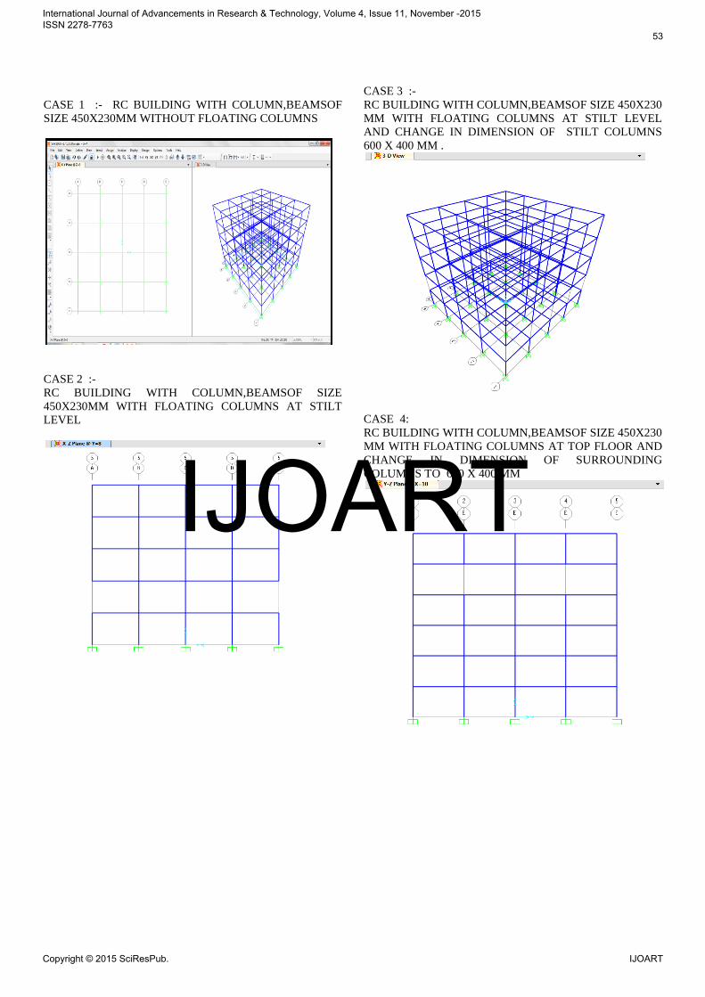
CASE 1 :- RC BUILDING WITH COLUMN,BEAMSOF
SIZE 450X230MM WITHOUT FLOATING COLUMNS
CASE 2 :-
RC BUILDING WITH COLUMN,BEAMSOF SIZE
450X230MM WITH FLOATING COLUMNS AT STILT
LEVEL
CASE 3 :-
RC BUILDING WITH COLUMN,BEAMSOF SIZE 450X230
MM WITH FLOATING COLUMNS AT STILT LEVEL
AND CHANGE IN DIMENSION OF STILT COLUMNS
600 X 400 MM .
CASE 4:
RC BUILDING WITH COLUMN,BEAMSOF SIZE 450X230
MM WITH FLOATING COLUMNS AT TOP FLOOR AND
CHANGE IN DIMENSION OF SURROUNDING
COLUMNS TO 600 X 400 MM
International Journal of Advancements in Research & Technology, Volume 4, Issue 11, November -2015 ISSN 2278-7763
53
Copyright © 2015 SciResPub. IJOART
IJOART

PUSH OVER CURVES
CASE 1:
CASE 2:
CASE 3:
CASE 4:
HINGE FORMATION
CASE 1:
CASE 2:
CASE 3:
CASE 4:
International Journal of Advancements in Research & Technology, Volume 4, Issue 11, November -2015 ISSN 2278-7763
54
Copyright © 2015 SciResPub. IJOART
IJOART

EVALUATION RESULTS
RESULT 1:
STEP DISPLACEMENT
KN BASE
FORCE
DISPLAC
MENT
CHANGE
IN %
BASE FORCE
CHANGE %
48 0.222433
2036.84
7 0.127312
1604.986
21.20
49.40
RESULT 2:
STEP DISPLACEM
ENT KN
BASE
FORCE
DISPLACME
NT CHANGE
IN %
BASE
FORCE
CHANG
E %
48
(COLU
MN
SIZE
.45 X
.23)
0.22243
2036.842
7(COL
UMN
SIZE .6
X .4 )
0.079255
2498.647
18.4
64.3
RESULT 3:
STEP DISPLACEM
ENT KN
BASE
FORCE
DISPLACM
ENT
CHANGE
IN %
BASE
FORCE
CHANGE
%
48
(COLU
MN
SIZE
.45 X
.23)
0.222433
2036.842
7(COL
UMN
SIZE .6
X .4 )
0.127312
2036.366
42.7369
0.0233
RESULTS AND DISSCUSSIONS
1. With the increase in the stilt column dimensions the
displacement varies and base force also increases.
2 .Increase in 150 mm dimension in slilt-cloumns results 62
% variation in the base force.
3.With increase in the surrounding columns near floating
columns. The base shear will be increased.
4. By providing floating columns at the top floor and with
increase in the surrounding columns the displacement and
base force decreases.
5.For existing rc buildings effected by earthquakes, and
tsunami the column size and be increased by method of
shorcreting.
REFERENCES
[1]. Srikanth.M.K, Yogeendri.R.Holebagilu, “Seismic
Response Of Complex Buildings With Floating Column For
Zone II and Zone V”, International journal of Engineering
Research-Online, Vol.2., Issue.4, 2014, ISSN: 2321-7758.
[2]. Spoorthi S K, Dr. Jagadish Kori G, “Effect Of Soft Story
On Tall Buildings At Various Stories By Pushover Analysis”,
International journal of Engineering Research-Online, Vol.2.,
Issue.3., 2014, ISSN: 2321-7758.
[3].RizaAinul Hakim, Mohammed SohaibAlama, Samir A.
Ashour, “Seismic Assessment of an RC Building Using Pushover Analysis”, Engineering, Technology & Applied Science Research Vol. 4, No. 3, 2014, 631-635.
[4]. Naga Sujani.S, Phanisha.K, MohanaRupa, Sunita Sarkar, P.Poluraju, “Comparison of behavior of a multistorey building situated in zone II and zone V, using pushover analysis by Sap 2000”, International Journal of Emerging Trends In Engineering And Development, Issue 2, Vol.2(March-2012), Pp. 480-487.
[5]. SukumarBehera, “Seismic Analysis Of Multistory Building With Floating Column” A Thesis Of National Institute Of Technology Rourkela, (2012), Pp. 21-93.
[6]. Amit V. Khandve. (2012), “Seismic Response of RC Frame Buildings with Soft Storeys”, International Journal of Engineering Research and Applications (IJERA), vol 2, Issue 3, pp 2100-2108.
[7]. Mehmet Inel, Hayri. B. Ozmen. (2008), “Effect of infill walls on soft story behavior in mid-rise RC Buildings”, The 14th World Conference on Earthquake Engineering, Beijing, China, pp 12-17.
[8]. Federal emergency management agency (FEMA 356), Nov 2000, is a report on Prestandard and commentary for the seismic rehabilitation of buildings prepared by American society of civil engineers.
[9]. Ri-Hui Zhang1 and T. T. Soong, Member, ASCE “Seismic Design of Viscoelastic Dampers for Structural Applications” J. Struct. Eng. 1992.118:1375-1
International Journal of Advancements in Research & Technology, Volume 4, Issue 11, November -2015 ISSN 2278-7763
55
Copyright © 2015 SciResPub. IJOART
IJOART