Embed Size (px)
DESCRIPTION
MOBILE COMMUNICATION
Citation preview
Cellular Concept___________________________________________________________________________________
REGIONAL TELECOM TRAINING CENTRE
LUCKNOW
Summer Training Programme
ON
Mobile Comunication- GSM,CDMA
1RTTC , Lucknow
Cellular Concept___________________________________________________________________________________
CELLULAR CONCEPTTraditional mobile service was structured similar to television broadcasting: One very
powerful transmitter located at the highest spot in an area would broadcast in a radius of up to fifty kilometers. The Cellular concept structured the mobile telephone network in a different way. Instead of using one powerful transmitter many low-powered transmitter were placed through out a coverage area. For example, by dividing metropolitan region into one hundred different areas (cells) with low power transmitters using twelve conversation (channels) each, the system capacity could theoretically be increased from twelve conversations using one hundred low power transmitters.
The cellular concept employs variable low power levels, which allows cells to be sized according to subscriber density and demand of a given area. As the populations grows, cells can be added to accommodate that growth. Frequencies used in one cell cluster can be reused in other cells. Conversations can be handed over from cell to cell to maintain constant phone service as the user moves between cells.
The cellular system design was pioneered by during’70s by Bell Laboratories in the United States, and the initial realization was known as AMPS (Advanced Mobile Phone Service). The AMPS cellular service was available in United States in 1983. AMPS is essentially generation 1 analog cellular system in contrast to generation 2 digital cellular systems of GSM and CDMA (1S-95).
CELLS :
A cell is the basic geographic unit of cellular system. The term cellular comes from the honeycomb areas into which a coverage region is divided. Cells are base stations transmitting over small geographic areas that are represented as hexagons. Each cell size varies depending upon landscape. Because of constraint imposed by natural terrain and man-made structures, the true shape of cell is not a perfect hexagon.
A group of cells is called a cluster. No frequencies are reused in a cluster.
Features of Digital Cellular Systems:
Small cells
Frequency reuse
Small, battery-powered handsets
Performance of handovers
CELLULAR SYSTEM CHARACTERISTICS
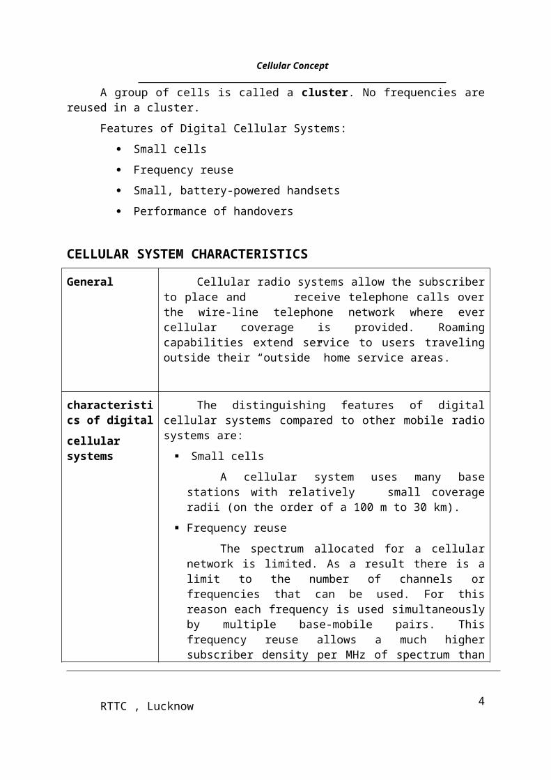
General Cellular radio systems allow the subscriber to place and receive telephone calls over the wire-line telephone network where ever cellular coverage is provided. Roaming capabilities extend service to users traveling outside their “outside” home service areas.
2RTTC , Lucknow
Cellular Concept___________________________________________________________________________________
characteristics of digital
cellular systems
The distinguishing features of digital cellular systems compared to other mobile radio systems are:
Small cells
A cellular system uses many base stations with relatively small coverage radii (on the order of a 100 m to 30 km).
Frequency reuse
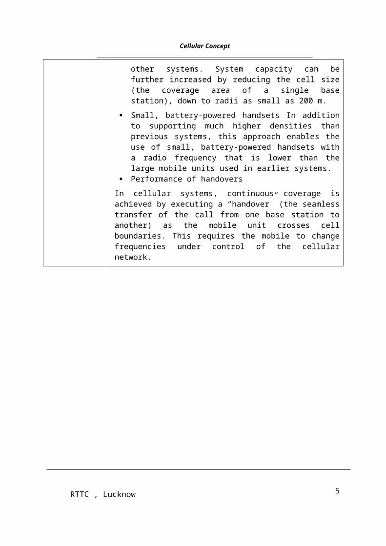
The spectrum allocated for a cellular network is limited. As a result there is a limit to the number of channels or frequencies that can be used. For this reason each frequency is used simultaneously by multiple base-mobile pairs. This frequency reuse allows a much higher subscriber density per MHz of spectrum than other systems. System capacity can be further increased by reducing the cell size (the coverage area of a single base station), down to radii as small as 200 m.
Small, battery-powered handsets In addition to supporting much higher densities than previous systems, this approach enables the use of small, battery-powered handsets with a radio frequency that is lower than the large mobile units used in earlier systems.
Performance of handovers
In cellular systems, continuous coverage is achieved by executing a “handover” (the seamless transfer of the call from one base station to another) as the mobile unit crosses cell boundaries. This requires the mobile to change frequencies under control of the cellular network.
FREQUENCY REUSE :
Why frequency reuse
The spectrum allocated for a cellular network is limited. As a result there is a limit to the number of frequencies or channels that can be used. A cellular network can only provide service to a large number of subscribers, if the channels allocated to it can be reused. Channel reuse is implemented by using the same channels within cells located at different positions in the cellular network service area.
Radio channels can be reused provided the separation between cells containing the same channel set is far enough apart so that co-channel interference can be kept below acceptable levels most of the time. Cells using the same channel set are called co-channel cells.
Cell clustering The figure on the opposite page shows an example. Within the
3RTTC , Lucknow
Cellular Concept___________________________________________________________________________________
service area (PLMN), specific channel sets are reused at a different location (another cell). In the example, there are 7 channel sets: A through G. Neighboring cells are not allowed to use the same frequencies. For this reason all channel sets are used in a cluster of neighboring cells. As there are 7 channel sets, the PLMN can be divided into clusters of 7 cells each. The figure shows three clusters.
The number of channel sets is called K. K is also called the reuse factor. In the figure, K=7. Valid values of K can be found using equation (where i and j are integers):
K=i²+j²+I*j
Explaining this equation is beyond the scope of this course. Some constraints to K are provided later in this chapter. Note that in the example: Cells are shaped ideally (hexagons). The distance between cells using the same channel set is always the same.
Other cell clusters
The figure on the opposite page shows some examples of possible clusters. The more cells in a cluster, the greater the separation between co-channel cells when Other clusters are deployed. The idea is to keep co-channel cell separation the same throughout the system area for cells of the same size. Some valid cluster sizes that allow this are: 1, 3, 4, 7, 9 and 12.
Procedure for locating co-channel cells
It is always possible to find cells using the same channel set, if only the value of K is known. The following procedure is used.
In the figure on the opposite page an example is shown with K = 19.
Signal attenuation With distance
Frequencies can be reused throughout a service area because radio signals typically attenuate with distance to the base station (or mobile station). When the distance between cells using the same frequencies becomes too small, co-channel
Interference might occur and lead to service interruption or unacceptable quality of service.
Step Action
1 Use the integer values i and j from the equation, and start
4RTTC , Lucknow
Cellular Concept___________________________________________________________________________________
With the upper left cell. Through this cell, draw the j-axis.
2 Draw the i-axis. To find the starting point for the i-axis, count j cells down the j-axis. In the example, one has to count 2 cells down (j=2). The positive direction of the i-axis is always two cell faces (120 degrees) relative to the positive direction of the j-axis.
3 Find the first co-channel cell. It is found by counting i cells in the positive i-axis direction. In the example, i = 3.
4 Find the other co-locating cells by repeating the previous steps. The
Starting point is again at the upper left cell, but now choose another
Direction for the j-axis (e.g. rotate the j-axis with 60 degrees, which is one cell face). As each cell has 6 faces, one will find 6 co-channel cells around the starting cells. These are the nearest located co-channel cells.
Capacity/Performance Trade-offs :
n If K increases, then performance increases
n If K increases, then call capacity decreases per cell
The number of sites to cover a given area with a given high traffic density, and hence the cost of the infrastructure, is determined directly by the reuse factor and the number of traffic channels that can be extracted from the available spectrum. These two factors are compounded in what is called spectral efficiency of the system. Not all systems allow the same performance in this domain: they depend in particular on the robustness of the radio transmission scheme against interference, but also on the use of a number of technical tricks, such as reducing transmission during the silences of a speech communication. The spectral efficiency, together with the constraints on the cell size, determines also the possible compromises between the capacity and the cost of the infrastructure. All this explains the importance given to spectral efficiency.
Many technical tricks to improve spectral efficiency were conceived during the system design and have been introduced in GSM. They increase the complexity, but this is balanced by the economical advantages of a better efficiency. The major points are the following:
The control of the transmitted power on the radio path aims at minimizing the average power broadcast by mobile stations as well as by base stations, whilst keeping transmission quality above a given threshold. This reduces the level of interference caused to the other communications;
5RTTC , Lucknow
Cellular Concept___________________________________________________________________________________Frequency hopping improves transmission quality at slow speeds through frequency
diversity, and improves spectral efficiency through interferer diversity;
Discontinuous transmission, where by transmission is suppressed when possible, allows a reduction in the interference level of other communications. Depending on the type of user information transmitted, it is possible to derive the need for effective transmission. In the case of speech, the mechanism called VAD (Voice Activity Detection) allows transmission requirements to be reduced by an important factor (typically, reduced by half);
The mobile assisted handover, whereby the mobile station provides measurements concerning neighboring cells, enables efficient handover decision algorithms aimed at minimizing the interference generated by the cell (whilst keeping the transmission quality above some threshold).
References:1. The GSM system for mobile communication-Michel Mouly & Marie- Bernadette Pautet.
2. GSM system Engineering-Asha Mehrotra (Artech House Publisher).
6RTTC , Lucknow
Cellular Concept___________________________________________________________________________________
GSM ARCHITECTUREINTRODUCTION
A GSM system is basically designed as a combination of three major subsystems: the network subsystem, the radio subsystem, and the operation support subsystem. In order to ensure that network operators will have several sources of cellular infrastructure equipment, GSM decided to specify not only the air interface, but also the main interfaces that identify different parts. There are three dominant interfaces, namely, an interface between MSC and the base Transceiver Station (BTS), and an Um interface between the BTS and MS.
GSM NETWORK STRUCTURE
Every telephone network needs a well-designed structure in order to route incoming called to the correct exchange and finally to the called subscriber. In a mobile network, this structure is of great importance because of the mobility of all its subscribers [1-4]. In the GSM system, the network is divided into the following partitioned areas.
GSM service area; PLMN service area; MSC service area; Location area; Cells.
The GSM service is the total area served by the combination of all member countries where a mobile can be serviced. The next level is the PLMN service area. There can be several within a country, based on its size. The links between a GSM/PLMN network and other PSTN, ISDN, or PLMN network will be on the level of international or national transit exchange. All incoming calls for a GSM/PLMN network will be routed to a gateway MSC. A gateway MSC works as an incoming transit exchange for the GSM/PLMN. In a GSM/PLMN network, all mobile-terminated calls will be routed to a gateway MSC. Call connections between PLMNs, or to fixed networks, must be routed through certain designated MSCs called a gateway MSC. The gateway MSC contains the interworking functions to make these connections. They also route incoming calls to the proper MSC within the network. The next level of division is the MSC/VLR service area. In one PLMN there can be several MSC/VLR service area. MSC/VLR is a role controller of calls within its jurisdiction. In order to route a call to a mobile subscriber, the path through links to the MSC in the MSC area where the subscriber is currently located. The mobile location can be uniquely identified since the MS is registered in a VLR, which is generally associated with an MSC.
The next division level is that of the LA’s within a MSC/VLR combination. There are several LA’s within one MSC/VLR combination. A LA is a part of the MSC/VLR service area in which a MS may move freely without updating location information to the MSC/VLR exchange that control the LA. Within a LA a paging message is broadcast in order to find the called mobile subscriber. The LA can be identified by the system using the Location Area Identity (LAI). The LA is used by the GSM system to search for a subscriber in a active state. Lastly, a LA is divided into many cells. A cell is an identity served by one BTS. The MS
7RTTC , Lucknow
Cellular Concept___________________________________________________________________________________
distinguishes between cells using the Base Station Identification code (BSIC) that the cell site broadcast over the air.
MOBILE STATION
The MS includes radio equipment and the man machine interface (MMI) that a
subscribe needs in order to access the services provided by the GSM PLMN. MS can be
installed in Vehicles or can be portable or handheld stations. The MS may include provisions
for data communication as well as voice. A mobile transmits and receives message to and
from the GSM system over the air interface to establish and continue connections through the
system .
Different type of MSs can provide different type of data interfaces. To provide a
common model for describing these different MS configuration, ”reference configuration” for
MS, similar to those defined for ISDN land stations, has been defined.
Each MS is identified by an IMEI that is permanently stored in the mobile unit. Upon
request, the MS sends this number over the signaling channel to the MSC. The IMEI can be
used to identify mobile units that are reported stolen or operating incorrectly.
Just as the IMEI identities the mobile equipment, other numbers are used to identity
the mobile subscriber. Different subscriber identities are used in different phases of call
setup. The Mobile Subscriber ISDN Number (MSISDN) is the number that the calling party
dials in order to reach the subscriber. It is used by the land network to route calls toward an
appropriate MSC. The international mobile subscribe identity (IMSI) is the primary function
of the subscriber within the mobile network and is permanently assigned to him. The GSM
system can also assign a Temporary Mobile Subscriber Identity (TMSI) to identity a mobile.
8RTTC , Lucknow

Cellular Concept___________________________________________________________________________________
This number can be periodically changed by the system and protect the subscriber from being
identified by those attempting to monitor the radio channel.
Functions of MS
The primary functions of MS are to transmit and receive voice and data over the air interface
of the GSM system. MS performs the signal processing function of digitizing, encoding, error
protecting, encrypting, and modulating the transmitted signals. It also performs the inverse
functions on the received signals from the BS.
In order to transmit voice and data signals, the mobile must be in synchronization
with the system so that the messages are the transmitted and received by the mobile at the
correct instant. To achieve this, the MS automatically tunes and synchronizes to the
frequency and TDMA timeslot specified by the BSC. This message is received over a
dedicated timeslot several times within a multiframe period of 51 frames. We shall discuss
the details of this in the next chapter. The exact synchronization will also include adjusting
the timing advance to compensate for varying distance of the mobile from the BTS.
The MS monitors the power level and signal quality, determined by the BER for
known receiver bit sequences (synchronization sequence), from both its current BTS and up
to six surrounding BTSs. This data is received on the downlink broadcast control channel.
The MS determines and send to the current BTS a list of the six best-received BTS signals.
The measurement results from MS on downlink quality and surrounding BTS signal levels
are sent to BSC and processed within the BSC. The system then uses this list for best cell
handover decisions.
9RTTC , Lucknow
Cellular Concept___________________________________________________________________________________MS keeps the GSM network informed of its location during both national and
international roaming, even when it is inactive. This enables the System to page in its present
LA.
The MS includes an equalizer that compensates for multi-path distortion on the
received signal. This reduces inter-symbol interface that would otherwise degrade the BER.
Finally, the MS can store and display short received alphanumeric messages on the
liquid crystal display (LCD) that is used to show call dialing and status information. These
messages are limited to 160 characters in length.
Power Levels
These are five different categories of mobile telephone units specified by the
European GSM system: 20W, 8W, 5W, 2W, and 0.8W. These correspond to 43-dBm, 39-
dBm, 37-dBm, 33-dBm, and 29-dBm power levels. The 20-W and 8-W units (peak power)
are either for vehicle-mounted or portable station use.
The MS power is adjustable in 2-dB steps from its nominal value down to 20mW (13
dBm). This is done automatically under remote control from the BTS, which monitors the
received power and adjusts the MS transmitter to the minimum power setting necessary for
reliable transmission.
SIM Card
As described in the first chapter, GSM subscribers are provided with a SIM card with
its unique identification at the very beginning of the service. By divorcing the subscriber ID
from the equipment ID, the subscriber may never own the GSM mobile equipment set. The
subscriber is identified in the system when he inserts the SIM card in the mobile equipment.
10RTTC , Lucknow
Cellular Concept___________________________________________________________________________________
This provides an enormous amount of flexibility to the subscribers since they can now use
any GSM-specified mobile equipment. Thus with a SIM card the idea of “Personalize” the
equipment currently in use and the respective information used by the network (location
information) needs to be updated. The smart card SIM is portable between Mobile Equipment
(ME) units. The user only needs to take his smart card on a trip. He can then rent a ME unit at
the destination, even in another country, and insert his own SIM. Any calls he makes will be
charged to his home GSM account. Also, the GSM system will be able to reach him at the
ME unit he is currently using.
The SIM is a removable SC, the size of a credit card, and contains an integrated
circuit chip with a microprocessor, random access memory (RAM), and read only memory
(ROM). It is inserted in the MS unit by the subscriber when he or she wants to use the MS to
make or receive a call. As stated, a SIM also comes in a modular from that can be mounted in
the subscriber’s equipment.
When a mobile subscriber wants to use the system, he or she mounts their SIM card
and provide their Personal Identification Number(PIN), which is compared with a PIN stored
within the SIM. If the user enters three incorrect PIN codes, the SIM is disabled. The PIN can
also be permanently bypassed by the service provider if requested by the subscriber.
Disabling the PIN code simplifies the call setup but reduces the protection of the user’s
account in the event of a stolen SIM.
International Mobile Subscriber Identity.
An IMSI is assigned to each authorized GSM user. It consists of a mobile country code (MSC), mobile network code (MNC), and a PLMN unique mobile subscriber identification number (MSIN). The IMSI is not hardware-specific. Instead, it is maintained on a SC by an authorized subscriber and is the only absolute identity that a subscriber has
11RTTC , Lucknow
Cellular Concept___________________________________________________________________________________
within the GSM system. The IMSI consists of the MCC followed by the NMSI and shall not exceed 15 digits.
TEMPORARY MOBILE SUBSCRIBER IDENTITY
A TMSI is a MSC-VLR specific alias that is designed to maintain user confidentiality. It is assigned only after successful subscriber authentication. The correlation of a TMSI to an IMSI only occurs during a mobile subscriber’s initial transaction with an MSC (for example, location updating). Under certain condition (such as traffic system disruption and malfunctioning of the system), the MSC can direct individual TMSIs to provide the MSC with their IMSI.
MOBILE STATION ISDN NUMBER
The MS international number must be dialed after the international prefix in order to obtain a mobile subscriber in another country. The MSISDN numbers is composed of the country code (CC) followed by the National Significant Number (N(S)N), which shall not exceed 15 digits.
The Mobile Station Roaming Number (MSRN)
The MSRN is allocated on temporary basis when the MS roams into another numbering area. The MSRN number is used by the HLR for rerouting calls to the MS. It is assigned upon demand by the HLR on a per-call basis. The MSRN for PSTN/ISDN routing shall have the same structure as international ISDN numbers in the area in which the MSRN is allocated. The HLR knows in what MSC/VLR service area the subscriber is located. At the reception of the MSRN, HLR sends it to the GMSC, which can now route the call to the MSC/VLR exchange where the called subscriber is currently registered.
INTERNATIONAL MOBILE EQUIPMENT IDENTITY
The IMEI is the unique identity of the equipment used by a subscriber by each PLMN and is used to determine authorized (white), unauthorized (black), and malfunctioning (gray) GSM hardware. In conjunction with the IMSI, it is used to ensure that only authorized usera are granted access to the system. An IMEI is never sent in cipher mode by MS.
BASE STATION SYSTEM
The BSS is a set of BS equipment (such as transceivers and controllers) that is in view by the MSC through a single A interface as being the entity responsible for communicating with MSs in a certain area. The radio equipment of a BSS may be composed of one or more cells. A BSS may consist of one or more BS. The interface between BSC and BTS is designed as an A-bis interface. The BSS includes two types of machines: the BTS in contact with the MSs through the radio interface and the BSC, the latter being in contact with the MSC. The function split is basically between transmission equipment, the BTS, and managing equipment at the BSC. A BTS compares radio transmission and reception devices, up to and including the antennas, and also all the signal processing specific to the radio interface. A single transceiver within BTS supports eight basic radio channels of the same TDM frame. A BSC is a network component in the PLMN that function for control of one or more BTS. It is a functional entity that handles common control functions within a BTS.
12RTTC , Lucknow
Cellular Concept___________________________________________________________________________________A BTS is a network component that serves one cell and is controlled by a BSC. BTS
is typically able to handle three to five radio carries, carrying between 24 and 40 simultaneous communication. Reducing the BTS volume is important to keeping down the cost of the cell sites.
An important component of the BSS that is considered in the GSM architecture as a part of the BTS is the Transcoder/Rate Adapter Unit (TRAU). The TRAU is the equipment in which coding and decoding is carried out as well as rate adoption in case of data. Although the specifications consider the TRAU as a subpart of the BTS, it can be sited away from the BTS (at MSC), and even between the BSC and the MSC.
The interface between the MSC and the BSS is a standardized SS7 interface (A-interface) that, as stated before, is fully defined in the GSM recommendations. This allows the system operator to purchase switching equipment from one supplier and radio equipment and the controller from another. The interface between the BSC and a remote BTS likewise is a standard the A-bis. In splitting the BSS functions between BTS and BSC, the main principle was that only such functions that had to reside close to the radio transmitters/receivers should be placed in BTS. This will also help reduce the complexity of the BTS.
Functions of BTS
As stated, the primary responsibility of the BTS is to transmit and receive radio signals from a mobile unit over an air interface. To perform this function completely, the signals are encoded, encrypted, multiplexed, modulated, and then fed to the antenna system at the cell site. Trans-coding to bring 13-kbps speech to a standard data rate of 16 kbps and then combining four of these signals to 64 kbps is essentially a part of BTS, though, it can be done at BSC or at MSC. The voice communication can be either at a full or half rate over logical speech channel. In order to keep the mobile synchronized, BTS transmits frequency and time synchronization signals over frequency correction channel (FCCH and BCCH logical channels. The received signal from the mobile is decoded, decrypted, and equalized for channel impairments.
Random access detection is made by BTS, which then sends the message to BSC. The channel subsequent assignment is made by BSC. Timing advance is determined by BTS. BTS signals the mobile for proper timing adjustment. Uplink radio channel measurement corresponding to the downlink measurements made by MS has to be made by BTS.
BTS-BSC CONFIGURATIONS
There are several BTS-BSC configurations: single site; single cell; single site; multicell; and multisite, multicell. These configurations are chosen based on the rular or urban application. These configurations make the GSM system economical since the operation has options to adapt the best layout based on the traffic requirement. Thus, in some sense, system optimization is possible by the proper choice of the configuration. These include omni directional rural configuration where the BSC and BTS are on the same site; chain and multidrop loop configuration in which several BTSs are controlled by a single remote BSC with a chain or ring connection topology; rural star configuration in which several BTSs are connected by individual lines to the same BSC; and sectorized urban
13RTTC , Lucknow
Cellular Concept___________________________________________________________________________________
configuration in which three BTSs share the same site amd are controlled by either a collocated or remote BSC.
In rural areas, most BSs are installed to provide maximum coverage rather then maximum capacity.
Transcoder
Depending on the relative costs of a transmission plant for a particular cellular operator, there may be some benefit, for larger cells and certain network topologies, in having the transcoder either at the BTS, BSC or MSC location. If the trascoder is located at MSC, they are still considered functionally a part of the BSS. This approach allows for the maximum of flexibility and innovation in optimizing the transmission between MSC and BTS.
The transcoder is the device that takes 13-Kbps speech or 3.6/6/12-Kbps data multiplexes and four of them to convert into standard 64-Kbps data. First, the 13 Kbps or the data at 3.6/6/12 Kbps are brought up to the level of 16 Kpbs by inserting additional synchronizing data to make up the difference between a 13-Kbps speech or lower rate data, and then four of them are combined in the transcoder to provide 64 Kpbs channel within the BSS. Four traffic channel can then be multiplexed on one 64-Kpbs circuit. Thus, the TRAU output data rate is 64 Kpbs. Then, up to 30 such 64-Kpbs channels are multiplexed onto a 2.048 Mpbs if a CEPT1 channel is provided on the A-bis interface. This channel can carry up to 120-(16x 120) traffic and control signals. Since the data rate to the PSTN is normally at 2 Mbps, which is the result of combining 30-Kbps by 64-Kbph channels, or 120- Kbps by 16-Kpbs channels.
BSC
The BSC, as discussed, is connected to the MSC on one side and to the BTS on the other. The BSC performs the Radio Resource (RR) management for the cells under its control. It assigns and release frequencies and timeslots for all MSs in its own area. The BSC performs the intercell handover for MSs moving between BTS in its control. It also reallocates frequencies to the BTSs in its area to meet locally heavy demands during peak hours or on special events. The BSC controls the power transmission of both BSSs and MSs in its area. The minimum power level for a mobile unit is broadcast over the BCCH. The BSC provides the time and frequency synchronization reference signals broadcast by its BTSs. The BSC also measures the time delay of received MS signals relative to the BTS clock. If the received MS signal is not centered in its assigned timeslot at the BTS, The BSC can direct the BTS to notify the MS to advance the timing such that proper synchronization takes place. The functions of BSC are as follows.
The BSC may also perform traffic concentration to reduce the number of transmission lines from the BSC to its BTSs, as discussed in the last section.
SWITCHING SUBSYSTEMS: MOBILE SWITCHING CENTER AND GATEWAY SWITCHING CENTER
The network and the switching subsystem together include the main switching functions of GSM as well as the databases needed for subscriber data and mobility
14RTTC , Lucknow
Cellular Concept___________________________________________________________________________________
management (VLR). The main role of the MSC is to manage the communications between the GSM users and other telecommunication network users. The basic switching function of performed by the MSC, whose main function is to coordinate setting up calls to and from GSM users. The MSC has interface with the BSS on one side (through which MSC VLR is in contact with GSM users) and the external networks on the other (ISDN/PSTN/PSPDN). The main difference between a MSC and an exchange in a fixed network is that the MSC has to take into account the impact of the allocation of RRs and the mobile nature of the subscribers and has to perform, in addition, at least, activities required for the location registration and handover.
The MSC is a telephony switch that performs all the switching functions for MSs located in a geographical area as the MSC area. The MSC must also handle different types of numbers and identities related to the same MS and contained in different registers: IMSI, TMSI,ISDN number, and MSRN. In general identities are used in the interface between the MSC and the MS, while numbers are used in the fixed part of the network, such as, for routing.
FUNCTIONS OF MSC
As stated, the main function of the MSC is to coordinate the set up of calls between GSM mobile and PSTN users. Specifically, it performs functions such as paging, resource allocation, location registration, and encryption.
Specifically, the call-handling function of paging is controlled by MSC. MSC coordinates the set up of call to and from all GSM subscribers operating in its areas. The dynamics allocation of access resources is done in coordination with the BSS. More specifically, the MSC decides when and which types of channels should be assigned to which MS. The channel identity and related radio parameters are the responsibility of the BSS, The MSC provides the control of interworking with different networks. It is transparent for the subscriber authentication procedure. The MSC supervises the connection transfer between different BSSs for MSs, with an active call, moving from one call to another. This is ensured if the two BSSs are connected to the same MSC but also when they are not . In this latter case the procedure is more complex, since more then one MSC in involved. The MSC performs billing on calls for all subscribers based in its areas. When the subscriber is roaming elsewhere, the MSC obtains data for the call billing from the visited MSC. Encryption parameters transfers from VLR to BSS to facilitate ciphering on the radio interface are done by MSC. The exchange of signaling information on the various interface toward the other network elements and the management of the interface themselves are all controlled by the MSC. Finally, the MSC serves as a SMS gateway to forward SMS messages from Short Message Service Centers (SMSC) to the subscribers and from the subscribers to the SMSCs. It thus acts as a message mailbox and delivery system.
VLR
The VLR is collocated with an MSC. A MS roaming in an MSC area is controlled by the VLR responsible for that area. When a MS appears in a LA, it starts a registration procedure. The MSC for that area notices this registration and transfers to the VLR the identify of the LA where the MS is situated. A VLR may be in charge of one or several MSC LA’s. The VLR constitutes the databases that support the MSC in the storage and retrieval of
15RTTC , Lucknow
Cellular Concept___________________________________________________________________________________
the data of subscribers present in its area. When an MS enters the MSC area borders, it signals its arrival to the MSC that stores its identify in the VLR. The information necessary to manage the MS is contained in the HLR and is transferred to the VLR so that they can be easily retrieved if so required.
DATA STORED IN VLR
The data contained in the VLR and in the HLR are more or less the same. Nevertheless the data are present in the VLR only as long as the MS is registered in the area related to that VLR. Data associated with the movement of mobile are IMSI, MSISDN, MSRN, and TMSI. The terms permanent and temporary, in this case, are meaningful only during that time interval. Some data are mandatory, others are optional.
HOME LOCATION REGISTER
The HLR is a database that permanently stores data related to a given set of subscribers. The HLR is the reference database for subscriber parameters. Various identification numbers and addresses as well as authentication parameters, services subscribed, and special routing information are stored. Current subscriber status including a subscriber’s temporary roaming number and associated VLR if the mobile is roaming, are maintained.
The HLR provides data needed to route calls to all MS-SIMs home based in its MSC area, even when they are roaming out of area or in other GSM networks. The HLR provides the current location data needed to support searching for and paging the MS-SIM for incoming calls, wherever the MS-SIM may be. The HLR is responsible for storage and provision of SIM authentication and encryption parameters needed by the MSC where the MS-SIM is operating. It obtains these parameters from the AUC.
The HLR maintains record of which supplementary service each user has subscribed to and provides permission control in granting services. The HLR stores the identification of SMS gateways that have messages for the subscriber under the SMS until they can be transmitted to the subscriber and receipt is knowledge.
Some data are mandatory, other data are optional. Both the HLR and the VLR can be implemented in the same equipment in an MSC (collocated). A PLMN may contain one or several HLRs.
AUTHENTICATION CENTER
The AUC stores information that is necessary to protect communication through the air interface against intrusions, to which the mobile is vulnerable. The legitimacy of the subscriber is established through authentication and ciphering, which protects the user information against unwanted disclosure. Authentication information and ciphering keys are stored in a database within the AUC, which protects the user information against unwanted disclosure and access.
In the authentication procedure, the key Ki is never transmitted to the mobile over the air path, only a random number is sent. In order to gain access to the system, the mobile must
16RTTC , Lucknow
Cellular Concept___________________________________________________________________________________
provide the correct Signed Response (SRES) in answer to a random number (RAND) generated by AUC.
Also, Ki and the cipher key Kc are never transmitted across the air interface between the BTS and the MS. Only the random challenge and the calculated response are transmitted. Thus, the value of Ki and Kc are kept secure. The cipher key, on the other hand, is transmitted on the SS7 link between the home HLR/AUC and the visited MSC, which is a point of potential vulnerability. On the other hand, the random number and cipher key is supposed to change with each phone call, so finding them on one call will not benefit using them on the next call.
The HLR is also responsible for the “authentication” of the subscriber each time he makes or receives a call. The AUC, which actually performs this function, is a separate GSM entity that will often be physically included with the HLR. Being separate, it will use separate processing equipment for the AUC database functions.
EQUIPMENT IDENTIFY REGISTER
EIR is a database that stores the IMEI numbers for all registered ME units. The IMEI uniquely identifies all registered ME. There is generally one EIR per PLMN. It interfaces to the various HLR in the PLMN. The EIR keeps track of all ME units in the PLMN. It maintains various lists of message. The database stores the ME identification and has nothing do with subscriber who is receiving or originating call. There are three classes of ME that are stored in the database, and each group has different characteristics.
White List: contains those IMEIs that are known to have been assigned to valid MS’s. This is the category of genuine equipment.
Black List: contains IMEIs of mobiles that have been reported stolen. Gray List: contains IMEIs of mobiles that have problems (for example, faulty
software, wrong make of the equipment). This list contains all MEs with faults not important enough for barring.
INTERWORKING FUNCTION GSM provided a wide range of data services to its subscribers. The GSM system
interface with the various forms of public and private data networks currently available. It is the job of the IWF to provide this interfacing capability.
The IWF, which in essence is a part of MSC, provides the subscriber with access to data rate and protocol conversion facilities so that data can be transmitted between GSM Data Terminal Equipment (DTE) and a land-line DTE.
ECHO CANCELER
EC is used on the PSTN side of the MSC for all voice circuits. The EC is required at the MSC PSTN interface to reduce the effect of GSM delay when the mobile is connected to the PSTN circuit. The total round-trip delay introduced by the GSM system, which is the result of speech encoding, decoding and signal processing, is of the order of 180 ms. Normally this delay would not be an annoying factor to the mobile, except when communicating to PSTN as it requires a two-wire to four-wire hybrid transformer in the circuit. This hybrid is required at the local switching office because the standard local loop is
17RTTC , Lucknow
Cellular Concept___________________________________________________________________________________
a two-wire circuit. Due to the presence of this hybrid, some of the energy at its four-wire receive side from the mobile is coupled to the four-wire transmit side and thus retransmitted to the mobile. This causes the echo, which does not effect the land subscriber but is an annoying factor to the mobile. The standard EC cancels about 70 ms of delay.
During a normal PSTN (land-to-land call), no echo is apparent because the delay is too short and the land user is unable to distinguish between the echo and the normal telephone “side tones” However, with the GSM round-trip delay added and without the EC, the effect would be irritating to the MS subscriber.
OPERATION AND MAINTENANCE CENTERThe OMC provides alarm-handling functions to report and log alarms generated by the other network entities. The maintenance
personnel at the OMC can define that criticality of the alarm. Maintenance cover both technical and administrative actions to maintain and correct the system operation, or to restore normal operations after a breakdown, in the shortest possible time.
The fault management functions of the OMC allow network devices to be manually or automatically removed from or restored to service. The status of network devices can be checked, and tests and diagnostics on various devices can be invoked. For example, diagnostics may be initiated remotely by the OMC. A mobile call trace facility can also be invoked. The performance management functions included collecting traffic statistics from the GSM network entities and archiving them in disk files or displaying them for analysis. Because a potential to collect large amounts of data exists, maintenance personal can select which of the detailed statistics to be collected based on personal interests and past experience. As a result of performance analysis, if necessary, an alarm can be set remotely.
The OMC provides system change control for the software revisions and configuration data bases in the network entities or uploaded to the OMC. The OMC also keeps track of the different software versions running on different subsystem of the GSM.
18RTTC , Lucknow
Cellular Concept___________________________________________________________________________________
GSM SERVICESIt is important to note that all the GSM services were not introduced since the
appearance of GSM but they have been introduced in a regular way. The GSM Memorandum of Understanding (MoU) defined four classes for the introduction of the different GSM services:
E1: introduced at the start of the service. E2: introduced at the end of 1991. Eh: introduced on availability of half-rate channels. A: these services are optional.
Three categories of services can be distinguished:
Teleservices. Bearer services. Supplementary Services. Teleservices
- Telephony (E1® Eh).
- Facsimile group 3 (E1).
- Emergency calls (E1® Eh).
- Teletex.
Short Message Services (E1, E2, A) Using these services, a message of a maximum of 160 alphanumeric characters can be sent to or from a mobile station. If the mobile is powered off, the message is stored. With the SMS Cell Broadcast (SMS-CB), a message of a maximum of 93 characters can be broadcast to all mobiles in a certain geographical area.
- Fax mail. Thanks to this service, the subscriber can receive fax messages at any fax machine.
- Voice mail. This service corresponds to an answering machine.
Bearer services
A bearer service is used for transporting user data. Some of the bearer services are listed below:
Asynchronous and synchronous data, 300-9600 bps (E1). Alternate speech and data, 300-9600 bps (E1). Asynchronous PAD (packet-switched, packet assembler/dissembler) access, 300-9600
bps (E1).
19RTTC , Lucknow
Cellular Concept___________________________________________________________________________________
Synchronous dedicated packet data access, 2400-9600 bps (E2). Supplementary Services
- Call Forwarding (E1). The subscriber can forward incoming calls to another number if the called mobile is busy (CFB), unreachable (CFNRc) or if there is no reply (CFNRy). Call forwarding can also be applied unconditionally (CFU).
- Call Barring. There are different types of `call barring' services:
Barring of All Outgoing Calls, BAOC (E1). Barring of Outgoing International Calls, BOIC (E1). Barring of Outgoing International Calls except those directed toward the Home PLMN
Country, BOIC-exHC (E1). Barring of All Incoming Calls, BAIC (E1) Barring of incoming calls when roaming (A). - Call holds (E2) puts an active call on hold.
- Call Waiting, CW (E2) informs the user, during a conversation, about another incoming call. The user can answer, reject or ignore this incoming call.
- Advice of Charge, AoC (E2) provides the user with online charge information.
- Multiparty service (E2) Possibility of establishing a multiparty conversation.
- Closed User Group, CUG (A). It corresponds to a group of users with limited possibilities of calling (only the people of the group and certain numbers).
- Calling Line Identification Presentation, CLIP (A). It supplies the called user with the ISDN of the calling user.
- Calling Line Identification Restriction, CLIR (A). It enables the calling user to restrict the presentation.
- Connected Line identification Presentation, CoLP (A). It supplies the calling user with the directory number he gets if his call is forwarded.
- Connected Line identification Restriction, CoLR (A). It enables the called user to restrict the presentation.
- Operator determined barring (A). Restriction of different services and call types by the operator.
20RTTC , Lucknow
Cellular Concept___________________________________________________________________________________
2 VAS
STK is SIM Tool Kit, in which various services are available to subscriber such as railway enquiry, news, cricket and many more. These services can be accessed from CELLONE menu.
Procedure of STK services:
Each BSNL SIM has an option Cellone in the menu. This option contains various Value added Services in different Menus/Submenus. Whenever a customer wants to use any of the services, he/she has to simply navigate through the corresponding Menu/Submenu, reach the concerned service and select it. The system automatically converts it to an SMS, sends it to the VAS provider and gets the reply. The options in this menu can be updated directly by the VAS provider, without intervention of the customer, by using Over The Air (OTA) equipment.
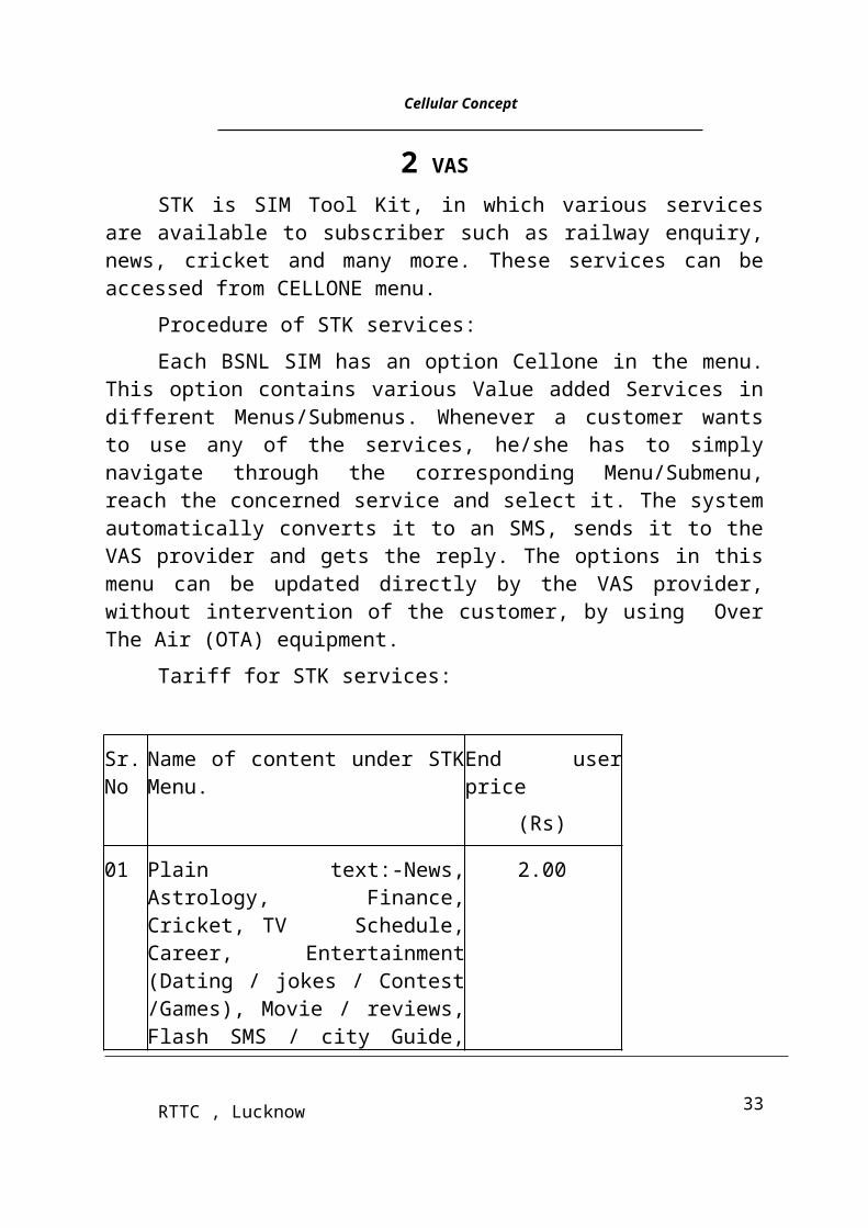
Tariff for STK services:
Sr. No
Name of content under STK Menu. End user price
(Rs)
01 Plain text:-News, Astrology, Finance, Cricket, TV Schedule, Career, Entertainment (Dating / jokes / Contest /Games), Movie / reviews, Flash SMS / city Guide, Airline info and Miscellaneous.
2.00
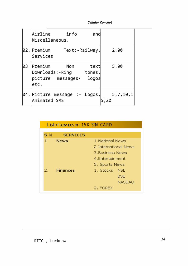
02. Premium Text:-Railway. Services 2.00
03 Premium Non text Downloads:-Ring tones, picture messages/ logos etc.
5.00
04. Picture message :- Logos, Animated SMS
5,7,10,15,20
21RTTC , Lucknow
Cellular Concept___________________________________________________________________________________
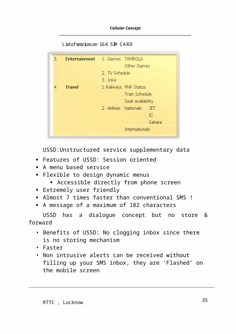
List of services on 16 K SIM CARD
List of services on 16 K SIM CARD
USSD:Unstructured service supplementary data
Features of USSD: Session oriented A menu based service Flexible to design dynamic menus
Accessible directly from phone screen
22RTTC , Lucknow
Cellular Concept___________________________________________________________________________________
Extremely user friendly Almost 7 times faster than conventional SMS ! A message of a maximum of 182 characters
USSD has a dialogue concept but no store & forward
• Benefits of USSD: No clogging inbox since there is no storing mechanism
• Faster• Non intrusive alerts can be received without filling up your SMS inbox,
they are ‘Flashed’ on the mobile screen
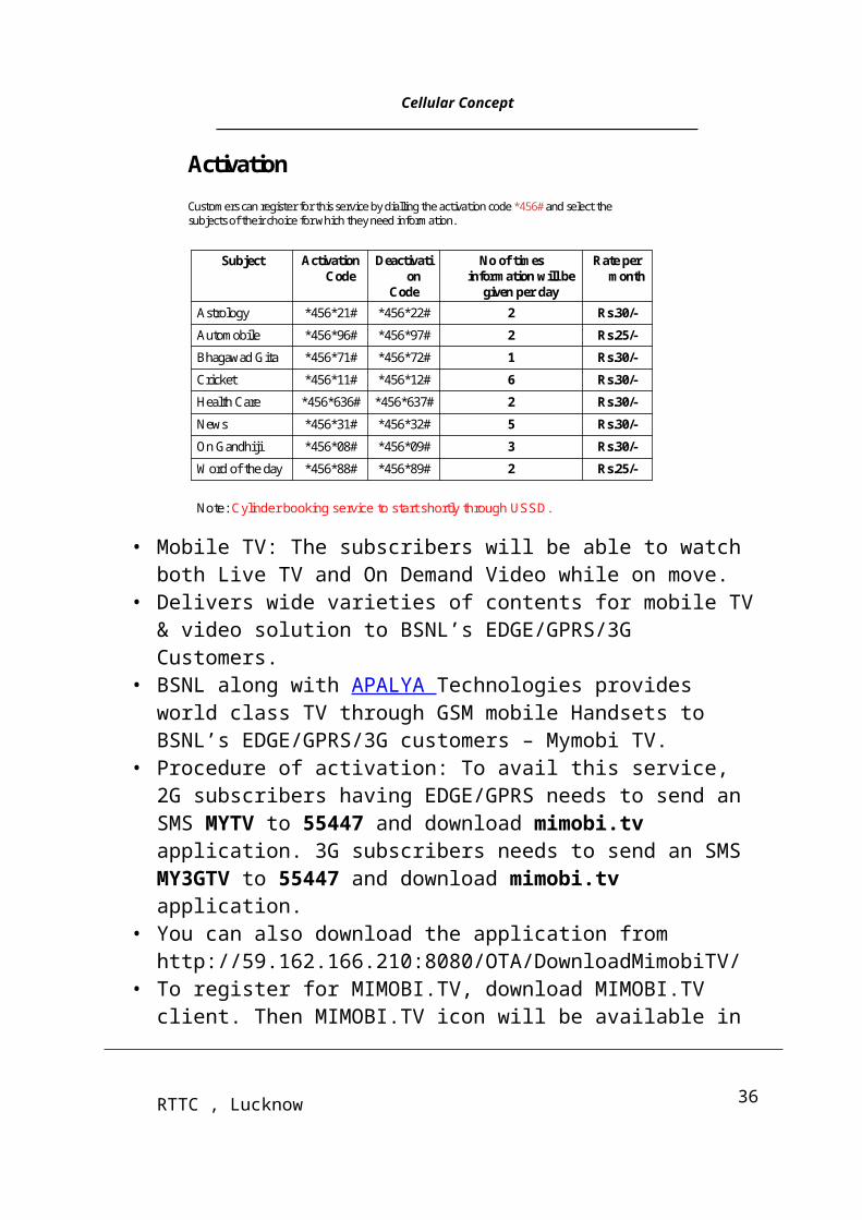
Activation
Customers can register for this service by dialling the activation code *456# and select the subjects of their choice for which they need information.
Rs.25/-2*456*89#*456*88#Word of the day
Rs.30/-3*456*09#*456*08#On Gandhiji
Rs.30/-5*456*32#*456*31#News
Rs.30/-2*456*637#*456*636#Health Care
Rs.30/-6*456*12#*456*11#Cricket
Rs.30/-1*456*72#*456*71#Bhagawad Gita
Rs.25/-2*456*97#*456*96#Automobile
Rs.30/-2*456*22#*456*21#Astrology
Rate per month
No of times information will be
given per day
Deactivation
Code
Activation Code
Subject
Note: Cylinder booking service to start shortly through USSD.
• Mobile TV: The subscribers will be able to watch both Live TV and On Demand Video while on move.
• Delivers wide varieties of contents for mobile TV & video solution to BSNL’s EDGE/GPRS/3G Customers.
• BSNL along with APALYA Technologies provides world class TV through GSM mobile Handsets to BSNL’s EDGE/GPRS/3G customers – Mymobi TV.
• Procedure of activation: To avail this service, 2G subscribers having EDGE/GPRS needs to send an SMS MYTV to 55447 and download mimobi.tv application. 3G subscribers needs to send an SMS MY3GTV to 55447 and download mimobi.tv application.
23RTTC , Lucknow
Cellular Concept___________________________________________________________________________________
• You can also download the application from http://59.162.166.210:8080/OTA/DownloadMimobiTV/
• To register for MIMOBI.TV, download MIMOBI.TV client. Then MIMOBI.TV icon will be available in your phone and click it to go through the registration process. Go to options button and select the subscription Plan either Monthly Plan or Pay-Per-View plan.
• From 15th Sep 2009 onwards, Browsing Charges in accordance with 2G Data Plans & 3G Data Plans will be applicable. Details regarding change in APN settings will be intimated later by Zones.
• Various TV channels available on ‘Mobile TV’ Application of BSNL are as follows:
(a) Non Premium Channels:- NDTV, AAJTAK, CARTOON NETWORK, TIMES NOW, ZOOM, BINDASS, INDIA TV, CNN-Mobile.
(b) Premium Channels:- SiddhiVinayak, Harikrishna, Kashi, HajiAli, Shirdi, FashionTV etc.
(c) Regional Channels:- ETV Bangla, RAJ TV, JAYA TV, JAYA Plus, ETV2, TV9, India Vision etc
For latest updates on contents, get in touch with zones lateron
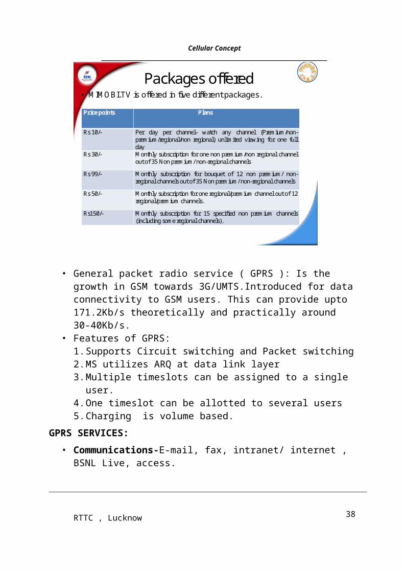
Packages offered• MIMOBI.TV is offered in five different packages.
Price points Plans
Rs 10/- Per day per channel- watch any channel (Premium/non-premium/regional/non regional) unlimited viewing for one full day
Rs 30/- Monthly subscription for one non premium/non regional channel out of 35 Non premium/ non-regional channels
Rs 99/- Monthly subscription for bouquet of 12 non premium/ non-regional channels out of 35 Non premium/ non-regional channels
Rs 50/- Monthly subscription for one regional/premium channel out of 12 regional/premium channels.
Rs150/- Monthly subscription for 15 specified non premium channels (including some regional channels).
24RTTC , Lucknow
Cellular Concept___________________________________________________________________________________
• General packet radio service ( GPRS ): Is the growth in GSM towards 3G/UMTS.Introduced for data connectivity to GSM users. This can provide upto 171.2Kb/s theoretically and practically around 30-40Kb/s.
• Features of GPRS: 1. Supports Circuit switching and Packet switching2. MS utilizes ARQ at data link layer3. Multiple timeslots can be assigned to a single user.4. One timeslot can be allotted to several users5. Charging is volume based.
GPRS SERVICES:
• Communications-E-mail, fax, intranet/ internet , BSNL Live, access.• Value added services -Information services, games, Entertainment
services.• Location-based applications –Resource training, Management service,
people finder• Advertising - restaurant receiving flashes of advertisement etc.
GPRS settings & usage:
Download the settings (automatic or manual),Subscribe for GPRS service and browse the site & start using the services. Browsing of Internet from Laptops and Desktop computers is possible by connecting the computer with the GPRS enabled mobile handset through a data cable or Infrared connectivity.
Multimedia Services: Multimedia Messaging Service (MMS) is a store and forward messaging service that allows mobile subscribers to exchange multimedia messages with other mobile subscribers. Photographs, Pictures, postcards, greeting cards presentation & static web pages can be sent and received like fixed telephone. Pictures, video, clips can be sent to internet site or friends through 3G mobile device.
25RTTC , Lucknow
Cellular Concept___________________________________________________________________________________
Multimedia Messaging - Any combination of media types
Hi Grandma!
Babysitting
tomorrow?
Video and
Audio
Images
Graphics
Music
• MMS messaging services: P2P communication and M2P communication.• Blackberry is a Mobile phone, which allows you to get instant e-mails
on your BlackBerry handheld. These e-mails are push-based e-mails and access is available to e-mails while roaming nationally and Internationally in select locations. These e-mails can be your official e-mails and also your personal e-mails. Blackberry also allows you to surf the internet. Blackberry works on the BSNL’s GSM network having GPRS /EDGE / 3G data enabled network. Via the BSNL’s data network your mails are sent and received from your Blackberry handheld.Blackberry works on the BSNL’s GPRS / EDGE / 3G platform. Blackberry works on the Push technology.In " Push technology" - the mail once reaches his / her mail server/ mailbox will be automatically indicated on the handheld over the GPRS / EDGE / 3G network. In this the customer need not log in or go through the above procedure. He has to log in once at the time of initiation of his account/service and then he is “Always ON, Always connected" to get his mail wherever GPRS / EDGE / 3G service is available.
26RTTC , Lucknow
Cellular Concept___________________________________________________________________________________
Overview of WLLINTRODUCTION : --Telecom Sector is advancing day by day with new services and new
facilities for customers. With the introduction of digital technology both in switching and transmission areas.
However one significant area, which has not changed much, is “Local Loop or Access Network”. This area, which connects the customer to telephone Exchange, known as “Last mile connectivity” mostly remains on copper network. Recent trends are to introduce either FIBRE or WIRELESS in this area.
COPPER BASED LOCAL LOOP : --Local Loop starts from the Main Distribution frame (MDF) of the
Telephone Exchange and passes through several flexibility points like Cabinet, Pillar and Distribution Point in U/G Cables and from DP to customer premises on overhead insulated copper wire (Drop Wire).
DISADVANTAGES OF COPPER NETWORK : --1 Copper is costly and the resource for copper makes it costlier
every day.
2 Installation of network is time consuming. In case of laying of cables.
3 Copper based network is prone to faults, electromagnetic interference, etc.
4 Maintenance is also difficult and time consuming.
5 Reconfiguration is not possible.
6 Expansion is also poses a hurdle since laying of additional cables always causes congestion in MDF and other flexibility points.
7 Bandwidth of operation in copper is limited even though DSL technologies, (which are distance limited) try to enhance the bandwidth.
8 Cost per line is dependent on the distance.
27RTTC , Lucknow
Cellular Concept___________________________________________________________________________________
Wireless has got the following advantages : -- 1. The cost of local loop by wire lines many times more than the cost
of local loop by WLL system.
2. The cost of wireline network is very costly due to use of copper.
3. The cost of wireline is depend on distance and this factor is not affected in WLL system.
4. If the customer widraw his srevices, the expenditure for the same is lost in the wireline system but in WLL system simply CPE are taken back and installed at another place.
5 In wireline system many termination points in the external plant causes faults time to time and this factor is not affected in WLL system.
6. WLL system may provides mobility, fax, internet and data transmission to all customer but in wireline system these facilities may be provided to ISDN customer only.
7. Wll system is very useful where cable laying is not possible.
TYPES OF WLL SYSTEM : --
(A) WLL Cor DECT : -- Cor is the monogram of the manufacturer & DECT stand for Digital Enhanced Cardless Telecommunication. It is an Uropean system and based on FDMA/TDMA/TDD Technology.
(B) WLL CDMA : -- It was lanched by Escort Vendor LG and based on Code Division Multiple Access. Some time it is called Fixed Cellular.
BASIC ARCHITECTURE OF WLL(COR DECT) : --Connectivity between LE (local exchange) and BSC (Base Station
Controller) can be either on V5.2 or R2MF or CCS7, depending on BSC functioning in RLU mode or independent switch respectively.
BSC is connected to several BTSs and each connection is generally 2Mbps. This connectivity is called “Abis”.BTS is connected to Mobile or Fixed Wireless Terminal (FWT) by air interface called “Um”.
INTRODUCTION TO CDMA2000 : --
The first operational cellular communication system was deployed in the Norway in 1981 and was followed by similar systems in the US and UK. These
28RTTC , Lucknow
Cellular Concept___________________________________________________________________________________
first generation systems provided voice transmissions by using frequencies around 900 MHz and analogue modulation.
The second generation (2G) of the wireless mobile network was based on low-band digital data signaling. While GSM and other TDMA-based systems have become the dominant 2G wirelesses technologies, CDMA technology IS 95A is recognized as providing clearer voice quality with less background noise, fewer dropped calls, enhanced security, greater reliability and greater network capacity.
The Second Generation (2G) wireless networks mentioned above are also mostly based on circuit-switched technology, are digital and expand the range of applications to more advanced voice services. 2G wireless technologies can handle some data capabilities such as fax and short message service at the data rate of up to 9.6 kbps, but it is not suitable for web browsing and multimedia applications. In the world of 2G, voice remains king while data is already dominant in wire line communications. And, fixed or wireless, all are affected by the rapid growth of the Internet.
Hence in mobile world also the aim was to achieve higher data speed. ITU also proposed the conceptual 3G.
3G OR IMT-2000:
International Mobile Telecommunications-2000 (IMT-2000) is the official International Telecommunication Union name for 3G and is an initiative intended to provide wireless access to global telecommunication infrastructure through both satellite and terrestrial systems, serving fixed and mobile phone users via both public and private telephone networks. Today's 3G specifications call for 144 Kb/s while the user is on the move in an automobile or train, 384 Kb/s for pedestrians, and ups to 2 Mb/s for stationary users. That is a big step up from 2G bandwidth using 8 to 13 Kb/s per channel to transport speech signals. But no single technology could be evolved as 3G.
THIRD GENERATION STANDARDS
CDMA2000/FDD-MC — CDMA2000 using Frequency Division Duplexing-Multicarrier (FDD-MC) mode. Here multicarrier implies N x 1.25 MHz channels overlaid on N existing IS-95 carriers or deployed on unoccupied spectrum. CDMA2000 includes:
1x —using a spreading rate of 1.2288 Mcps
29RTTC , Lucknow
Cellular Concept___________________________________________________________________________________
3x —using a spreading rate of 3 x 1.2288 Mcps or 3.6864 Mcps
1xEV-DO (1x Evolution – Data Optimized)—using a spreading rate of 1.2288 Mcps optimized for data
WCDMA/FDD-DS —Wideband CDMA (WCDMA) Frequency Division Duplexing-Direct Sequence spreading (FDD-DS) mode. This has a single 5 MHz channel. WCDMA uses a single carrier per channel and employs a spreading rate of 3.84 Mcps.
UTRA TDD/ TD-SCDMA — Universal Mobile Telephone Services Terrestrial Radio Access (UTRA) and TD-SCDMA. These are Time Division Duplexed (TDD) standards aimed primarily at asymmetric services used in unpaired (i.e., no separate uplink and downlink) bands. TD-SCDMA is based on a synchronous Time Division scheme for TDD and wireless local loop applications. The frame and slot structure are the same as W-CDMA. However, in TDD mode each slot can be individually allocated either the uplink or the downlink.
ADVANTAGES OF CDMA2000:--
CDMA2000 is backward compatible with IS-95. Thus a network that is converted to CDMA2000 from IS-95 will support users with IS-95 handsets. A motivating factor for migration to CDMA2000-enabled handsets is that it permits use of enhanced data service and increases the voice capacity of the network. The voice capacity of a CDMA2000 network increases as the percentage of subscribers with CDMA2000 handsets increases. IS-95 handsets do not contribute to this capacity improvement.
It reuses and builds on the full complement of existing CDMA air interface and network standards. Both IS-95 and CDMA2000 equipped mobiles can operate on the same frequency assignment. Existing IS-95 networks can be converted to CDMA2000 without impact to existing IS-95 mobiles. Network can “evolve” as users migrate from IS-95 mobiles to CDMA2000 mobiles.
NEW CONCEPTS IN THE CDMA2000 PHYSICAL LAYER:
The following are the new additions in CDMA 2000 from IS95.
1 Spreading Rate 1 (1x) and Spreading Rate 3 (3x)
2 Logical Channels
3 Radio Configurations
4 Many new Physical Channels
30RTTC , Lucknow
Cellular Concept___________________________________________________________________________________
5 Transmit Diversity Pilot Channels
6 Enhanced Access Channel procedures
7 Reverse Link Pilot Channel
Spreading Rates
CDMA2000 supports two different spreading rates:
1 Spreading Rate 1— also called “1x”
Both Forward and Reverse Channels use a single direct-sequence spread carrier with a
chip rate of 1.2288 Mcps.
2 Spreading Rate 3— also called “3x” or MC (Multi-Carrier)
Forward Channels use three direct-sequence spread carriers each with a chip rate of
1.2288 Mcps. Reverse Channels use a single direct-sequence spread carrier with a chip rate of 3.6864Mcps.
As such SR3 appears to be extinct.
Physical and Logical Channels:
In IS 95A, in the forward link Pilot, Sync, Paging and Traffic Channels exist whereas in reverse link Access and traffic channel are available. All overhead information is carried on the Paging Channel. During conversation or in dedicated mode the signaling info is exchanged by either fully or partially clearing the traffic. CDMA2000 technology defines new Physical and Logical Channels for the transport of user data and signaling information.
A Physical Channel is a communication path between the mobile and the Base Station, described in terms of the digital coding and RF characteristics.
A Logical Channel is a communication path within the protocol layers of either the Base Station or the mobile. Information is grouped onto a Logical Channel based on criteria such as these:
3 Is it for a single user or for multiple users?
4 Is it signaling or user data?
5 Is the direction of the transfer Forward or Reverse?
31RTTC , Lucknow
Cellular Concept___________________________________________________________________________________
The information on a Logical Channel is ultimately carried on one or more Physical Channels. Mappings are defined between Physical and Logical Channels. These mappings may be permanent or may be defined only for the duration of a call. (e.g) The Forward Common Signaling Channel (f-csch) carries information that may ultimately be mapped onto the Forward Sync Channel (F-SYNCH), the Forward Paging Channel (F-PCH), and the Forward Broadcast Control Channel (F-BCCH).
CDMA2000 PHYSICAL CHANNEL NAMING
CDMA2000 LOGICAL CHANNEL NAMING
A Logical Channel name consists of three lowercase letters followed by “ch” (channel).
A hyphen is used after the first letter. Logical Channel names are differentiated by:
1 Direction (Forward or Reverse)
2 Whether the information is shared by all users (common) or specific to an individual user (dedicated)
3 Whether the information is control information (signaling) or user information
For Common Signaling Channels, the mappings shown assume that all Common Signaling Physical Channels are supported (F-BCCH, F-CCCH, F-PCH, R-EACH, and R-ACH). If the Base Station is configured to support only the TIA/EIA-95 compatible common channels, then the F-BCCH, F-CCCH, and R-EACH channel are not present in the mapping.
For Dedicated Channels, the mapping is established for each call, as a function of what services are in use (voice, circuit-switched data, packet data).
Radio Configurations:
A Radio Configuration (RC) defines the following characteristics of a Forward or Reverse Traffic Channel, Viz Rate Set, Spreading Rate Channel Coding (Turbo or convolutional), Channel Coding Rate, Modulation (QPSK or BPSK)and Transmit Diversity Allowed.
32RTTC , Lucknow
Cellular Concept___________________________________________________________________________________
IS-2000 defines Radio Configurations:
– RC1 and RC2 correspond to IS-95 A/B Rate Set 1 and Rate Set 2 respectively
– RC3 through RC9 on the Forward link
– RC3 through RC6 on the Reverse link
Forward Link radio configuration:
Reverse Link radio configuration:
Variable Length Walsh Codes:
Walsh Code used in IS95 is 64 chips long. CDMA20001x can use Walsh Codes up to 128 Chips long. Higher data rate channels use shorter length Walsh codes to maintain a constant chip rate. Using one of the shorter Walsh codes precludes using all longer codes that contain the bit pattern of the shorter code.
Forward Link Code Channels:
The Forward Pilot, Sync, and Paging Channels are compatible with TIA/EIA-95A/B. In Radio Configurations 1 and 2, the Fundamental and Supplemental Channels are backward compatible. In these configurations, the maximum number of Supplemental Channels is seven, which allows the transmission rate to reach up to 115.2 kbps.
As in TIA/EIA-95A/B, the Power Control Sub channel is associated with the Fundamental Channel for Radio Configurations 1 and 2.
The Forward Link Channels are assigned as follows:
1 W0 64 reserved for Forward Pilot Channel
2 W32 64 reserved for Sync Channel
3 W1 64 to W7 64 reserved for Paging Channels
Wn 64 may be used for Radio Configurations 1 and 2 Fundamental and Supplemental Channels, for 0 < n < 64, except for those channels used for Sync and Paging Channels
33RTTC , Lucknow
Cellular Concept___________________________________________________________________________________
New Common Channels:
CDMA2000 introduces several new Forward Link Common Channels:
1 Pilot Channels – If transmit diversity is supported; one or more Pilots may be used.The auxiliary Pilot Channels may be used for smart antenna applications.
2 Quick Paging Channel – This channel provides for improved slotted mode operation and improved battery life for the mobile. Walsh codes W80, W48 and W112 are reserved for Quick Paging Channels, if the Base Station supports Quick Paging Channels.
3 Common Control Channel – This channel carries mobile-directed messages for CDMA2000 compatible mobiles.
4 Broadcast Channel – This channel carries broadcast messages for CDMA2000 compatible mobiles, including overhead messages and broadcast Short Message Service (SMS) messages.
5 Common Power Control Channel – This channel is used with Enhanced Access Channel Procedures (Reservation Mode), to send power control bits to the mobile so that Access Channel messages may be sent under power control.
6 Common Assignment Channel – This channel is used with Enhanced Access Channel Procedures (Reservation Mode) to assign the Reverse Common Control Channel (R-CCCH) and Common Power Control Sub channel.
New Dedicated Channels:
CDMA2000 introduces several new Forward Link Dedicated Channels:
1 Forward Fundamental Channel – This channel is used for the transmission of user and signaling information to a specific mobile during a call. Each Forward Traffic Channel may contain one Forward Fundamental Channel.
2 Forward Dedicated Control Channel – This channel is used for transmission of user and signaling information to a specific mobile during a call. Each Forward Traffic Channel may contain one Forward Dedicated Control Channel.
3 Forward Supplemental Channel (valid for Radio Configurations 3
34RTTC , Lucknow
Cellular Concept___________________________________________________________________________________
thro 9) This channel is used for the transmission of user information to a specific mobile during a call. This is typically used for high-speed data applications. Each Forward Traffic Channel may contain up to two Supplemental Channels.
4 Power Control Subchannel – This subchannel is typically associated with the Fundamental Channel, but if the F-FCH is not used for a given call, then it is associated with the Dedicated Control Channel (F-DCCH).
5 All of the CDMA2000 dedicated channels can be established using the TIA/EIA Paging (F-PCH) and Access (R-ACH) Channels.
Reverse Link Channels:
The CDMA2000 Reverse Link Channels are:
1 _ Access Channel (R-ACH)
2 _ Reverse Pilot Channel (R-PICH)
3 _ Enhanced Access Channel (R-EACH)
4 _ Reverse Common Control Channel (R-CCCH)
5 _ Reversed Dedicated Control Channel (R-DCCH)
6 _ Reverse Fundamental Channel (R-FCH)
7 _ Reverse Supplemental Channel (R-SCH)
8 _ Reverse Supplemental Code Channel (R-SCCH)
The Access Channel and Reverse Supplemental Channel are retained for backward compatibility with TIA/EIA-95A/B. For Radio Configurations 1 and 2, the channel structure for the Reverse Fundamental Channel and Reverse Supplemental Channel is the same as the channel structure of Rate Set 1 and Rate Set 2 used in TIA/EIA-95A/B.
Reverse Common and Dedicated Channels
Reverse Link Common Channels are used by multiple mobiles primarily for a brief exchange of information between a mobile and a Base Station. The Reverse Link Common Channels are:
1 _ Access Channel (R-ACH)
35RTTC , Lucknow
Cellular Concept___________________________________________________________________________________
2 _ Enhanced Access Channel (R-EACH)
3 _ Reverse Common Control Channel (R-CCCH)
Reverse Link Dedicated Channels are assigned to a single mobile for the duration of a call. The Reverse Link Dedicated Channels include:
1 _ Reverse Dedicated Control Channel (R-DCCH)
2 _ Reverse Fundamental Channel (R-FCH)
3 _ Reverse Supplemental Channel (R-SCH)
4 _ Reverse Supplemental Code Channel (R-SCCH)
The Reverse Pilot Channel is used with both Common and Dedicated Channels.
DATA MULTIPLEXING
CDMA2000 can multiplex data from multiple sources (e.g., signaling, voice, and data) onto one or more Physical Channels. Data can be multiplexed in one or two Supplemental Channels.
TIA/EIA-95 A/B COMPATIBLE ACCESS CHANNEL PROCEDURES
If the mobile monitors the Paging Channel (F-PCH), then its access attempts are made on the Access Channel (R-ACH). These procedures are identical to TIA/EIA-95 A/B access procedures.
CDMA2000 ENHANCED ACCESS CHANNEL PROCEDURES
If the mobile monitors the Forward Common Control Channel (F-CCCH) and Broadcast Control Channel (F-BCCH), then its access attempts are made on the Enhanced Access Channel (R-EACH) using the CDMA2000 enhanced access procedure.
36RTTC , Lucknow
Cellular Concept___________________________________________________________________________________
OVERVIEW OF WCDMABACKGROUND
There has been a tremendous growth in wireless communication technology over the past decade. The significant increase in subscribers and traffic, new bandwidth consuming applications such as gaming, music down loading and video streaming will place new demands on capacity. The answer to the capacity demand is the provision of new spectrum and the development of a new technology – Wideband CDMA or hereinafter referred to as WCDMA. WCDMA was developed in order to create a global standard for real time multimedia services that ensured international roaming. With the support of ITU (International Telecommunication Union) a specific spectrum was allocated – 2GHz for 3G telecom systems. The work was later taken over by the 3GPP (3rd Generation Partnership Project), which is now the WCDMA specification body with delegates from all over the world. Ericsson has for a long time played a very active role in both ITU and 3GPP and is a major contributor to WCDMA and the fulfillment of the vision of a global mobile telecommunication system.
WCDMA A DEVELOPMENT FROM GSM AND CDMA
Naturally there are a lot of differences between WCDMA and GSM systems, but there are many similarities as well. The GSM Base Station Subsystem (BSS) and the WCDMA Radio Access Network (RAN) are both connected to the GSM core network for providing a radio connection to the handset. Hence, the technologies can share the same core network. Furthermore, both GSM BSS and WCDMA RAN systems are based on the principles of a cellular radio system. The GSM Base Station Controller (BSC) corresponds to the WCDMA Radio Network Controller (RNC). The GSM Radio Base Station (RBS) corresponds to the WCDMA RBS, and the A-interface of GSM was the basis of the development of the Iu-interface of WCDMA, which mainly differs in the inclusion of the new services offered by WCDMA. The significant differences, apart from the lack of interface between the GSM BSCs and an insufficiently specified GSM Abis-interface to provide multi-vendor operability, are more of a systemic matter. The GSM system uses TDMA (Time Division Multiple Access) technology with a lot of radio functionality based on managing the timeslots. The WCDMA system on the other hand uses CDMA, as described below, which means that both the hardware and the control functions are different. Examples of WCDMA-specific functions are fast power control and soft handover.
Code Division Multiple Access and WCDMA
Code Division Multiple Access (CDMA) is a multiple access technology where the users are separated by unique codes, which means that all users can use the same frequency and transmit at the same time. With the fast development in signal processing, it has become feasible to use the technology for wireless communication, also referred to as WCDMA and CDMA2000. In cdmaOne and CDMA2000, a 1.25 MHz wide radio signal is multiplied by a spreading signal (which is a pseudo-noise code sequence) with a higher rate than the data rate of the message. The resultant signal appears as seemingly random, but if the intended recipient has the right code, this process is reversed and the original signal is extracted. Use
37RTTC , Lucknow
Cellular Concept___________________________________________________________________________________
of unique codes means that the same frequency is repeated in all cells, which is commonly referred to as a frequency re-use of 1.
WCDMA is a step further in the CDMA technology. It uses a 5 MHz wide radio signal and a chip rate of 3.84 Mcps, which is about three times higher than the chip rate of CDMA2000 (1.22 Mcps). The main benefits of a wideband carrier with a higher chiprate are:
• Support for higher bit rates
• Higher spectrum efficiency thanks to improved trunking efficiency (i.e. a better statistical averaging)
• Higher QoS
Further, experience from second-generation systems like GSM and cdmaOne has enabled improvements to be incorporated in WCDMA. Focus has also been put on ensuring that as much as possible of WCDMA operators’ investments in GSM equipment can be reused. Examples are the re-use and evolution of the core network, the focus on co-siting and the support of GSM handover. In order to use GSM handover the subscribers need dual mode handsets.
RADIO NETWORK FUNCTIONALITY
For optimal operation of a complete wireless system i.e. from handset to radio access network (RAN) several functions are needed to control the radio network and the many handsets using it. All functions described in this section, except for Handover to GSM, are essential and therefore necessary for a WCDMA system.
38RTTC , Lucknow
Cellular Concept___________________________________________________________________________________
Power control
The power control regulates the transmit power of the terminal and base station, which results in less interference and allows more users on the same carrier. Transmit power regulation thus provides more capacity in the network. With a frequency re-use of 1, it is very important to have efficient power control in order to keep the interference at a minimum. For each subscriber service the aim is that the base station shall receive the same power level from all handsets in the cell regardless of distance from the base station. If the power level from one handset is higher than needed, the quality will be excessive, taking a disproportionate share of the resources and generating unnecessary interference with the other subscribers in the network. On the other hand, if power levels are too low this will result in poor quality. In order to keep the received power at a suitable level, WCDMA has a fast power control that pdates power levels 1500 times every second. By oing that the rapid change in the radio channel is handled. To ensure good performance, power control is implemented in both the up-link and the down-link, which means that both the output powers of the handset and the base station are frequently updated. Power control also gives rise to a phenomenon called “cell breathing”. This is the trade-off between coverage and capacity, which means that the size of the cell varies depending on the traffic load. When the number of subscribers in the cell is low (low load), good quality can be achieved even at a long distance from the base station. On the other hand, when the number of users in the cell is high, the large number of subscribers generates a high interference level and subscribers have to get closer to the base station to achieve good quality.
Soft and softer handover
With soft handover functionality the handset can communicate simultaneously with two or more cells in two or more base stations. This flexibility in keeping the connection open to more than one base station results in fewer lost calls, which is very important to the operator. To achieve good system performance with a frequency re-use of 1 and power control, soft and softer handover is required. Soft and softer handover enables the handset to maintain the continuity and quality of the connection while moving from one cell to another. During soft or softer handover, the handset will momentarily adjust its power to the base station that requires the smallest amount of transmit power and the preferred cell may change very rapidly. The difference between soft and softer handover is that during soft handover, the handset is connected to multiple cells at different base stations, while during softer handover, the handset is connected to multiple cells at the same base station. A drawback with soft handover is that it requires additional hardware resources on the network side, as the handset has multiple connections. In a well-designed radio network, 30–40 % of the users will be in soft or softer handover.
39RTTC , Lucknow
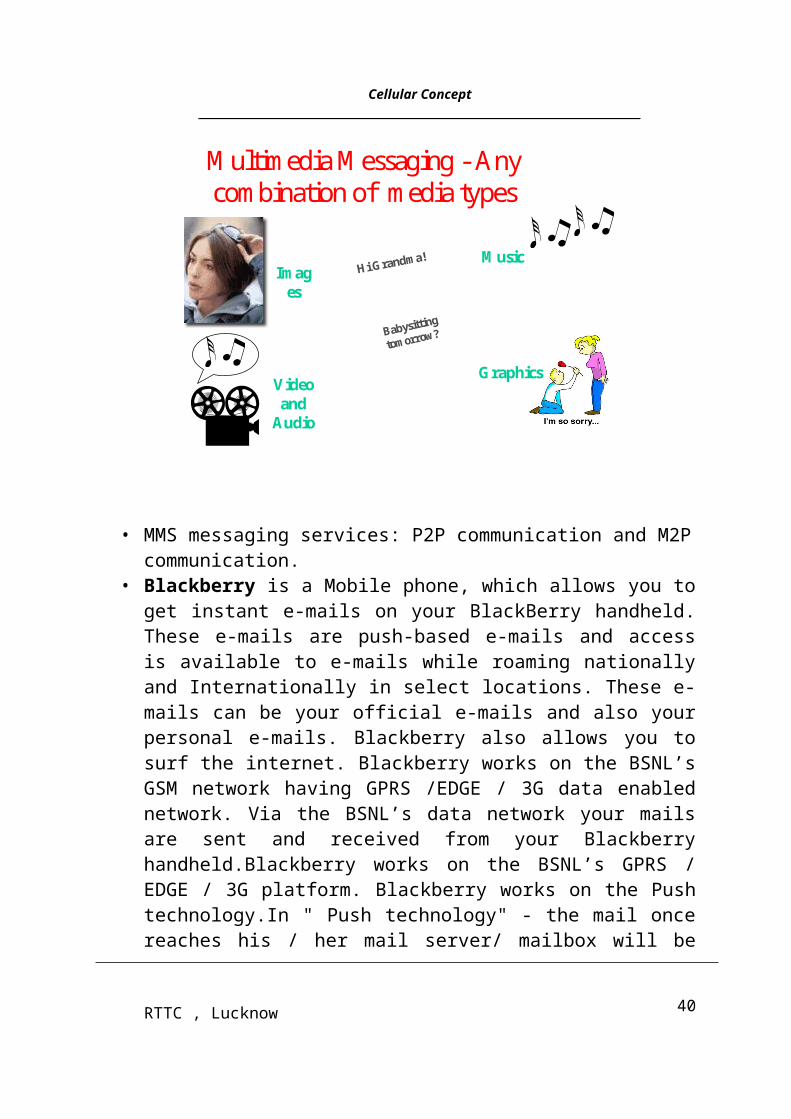
Cellular Concept___________________________________________________________________________________
Handover to GSM (inter-system handover)
40RTTC , Lucknow
Cellular Concept___________________________________________________________________________________When WCDMA was standardized a key aspect was to ensure that existing
investments could be re-used as much as possible. One example is handover between the new (WCDMA) network and the existing (GSM) network, which can be triggered by coverage, capacity or service requirements. Handover from WCDMA to GSM, for coverage reasons, is initially expected to be very important since operators are expected to deploy WCDMA gradually within their existing GSM network. When a subscriber moves out of the WCDMA coverage area, a handover to GSM has to be conducted in order to keep the connection. Handover between GSM and WCDMA can also have a positive effect on capacity through the possibility of load sharing. If for example the numbers of subscribers in the GSM network is close to the capacity limit in one area, handover of some subscribers to the WCDMA network can be performed. Another function that is related to inter-system handover is the compressed mode. When performing handover to GSM, measurements have to be made in order to identify the GSM cell to which the handover will be made. The compressed mode is used to create the measurement periods for the handset to make the required measurements. This is typically achieved by transmitting all the information during the first 5 milliseconds of the frame with the remaining 5 milliseconds being used for measurements on the other systems.
41RTTC , Lucknow
Cellular Concept___________________________________________________________________________________
Inter-frequency handover (intra-system handover)
The need for inter-frequency handover occurs in high capacity areas where multiple 5 MHz WCDMA carriers are deployed. Inter-frequency handover, which is handover between WCDMA carriers on different frequencies, has many similarities with GSM handover, for example the compressed mode functionality.
Channel type switching
In WCDMA there are different types of channels that can be used to carry data in order to maximize the total traffic throughput. The two most basic ones are common channels and dedicated channels. Channel type switching functionality is used to move subscribers between the common and the dedicated channel, depending on how much information the subscriber needs to transmit. The dedicated channel is used when there is much information to transmit, such as a voice conversation or downloading a web page. It utilizes the radio resources efficiently as it supports both power control and soft handover. The common channel, on the other hand, is less spectrum efficient. One benefit is that the common channel reduces delays as many subscribers can share the same resource. Hence it is the preferred channel for the transfer of very limited information.
Admission control
As there is a very clear trade-off between coverage and capacity in WCDMA systems, the admission control functionality is used to avoid system overload and to provide the planned coverage. When a new subscriber seeks access to the network, admission control estimates the network load and based on the new expected load, the subscriber is either admitted or blocked out. By this the operator can maximize the network usage within a set of network quality levels, i.e. levels depending on what kind of service/information the subscriber wants to use.
Congestion control
Even though an efficient admission control is used, overload may still occur, which is mainly caused by subscribers moving from one area to another area. If overload occurs, four different actions can be taken. First, congestion control is activated and reduces the bit rate of non real-time applications, to resolve the overload. Second, if the reduced bit rate activity is not sufficient, the congestion control triggers the inter- or intra-frequency handover, which moves some sub- scribers to less loaded frequencies. Third, handover of some subscribers to GSM and forth action is to discontinue connections, and thus protect the quality of the remaining connections.
Synchronization
One of the basic requirements when WCDMA was standardized was to avoid dependence on external systems for accurate synchronization of base stations. This has been achieved by a mechanism, where the handset, when needed, measures the synchronization offset between the cells and reports this to the network. In addition, there is also an option to use an external source, such as GPS, for synchronizing the nodes, i.e. to always provide the best solution both asynchronous and synchronous nodes are supported
42RTTC , Lucknow
Cellular Concept___________________________________________________________________________________
BASIC ARCHITECTURE CONCEPTS/ SYSTEM OVERVIEW
In this section some fundamental views of the WCDMA Radio Access Network will be presented. This includes the WCDMA RAN architecture itself, the radio interface protocol architecture, the Radio Access Bearer concept and the role of the transport network in a WCDMA RAN.
Radio Access Network (RAN) Architecture
The main purpose of the WCDMA Radio Access Network is to provide a connection between the handset and the core network and to isolate all the radio issues from the core network. The advantage is one core network supporting multiple access technologies. The WCDMA Radio Access Network consists of two types of nodes:
Radio Base Station (Node B)
The Radio Base Station handles the radio transmission and reception to/from the handset over the radio interface (Uu). It is controlled from the Radio Network Controller via the Iub interface. One Radio Base Station can handle one or more cells.
Radio Network Controller (RNC)
43RTTC , Lucknow
Cellular Concept___________________________________________________________________________________The Radio Network Controller is the node that controls all WCDMA Radio Access
Network functions. It connects the WCDMA Radio Access Network to the core network via the Iu interface. There are two distinct roles for the RNC, to serve and to control. The Serving RNC has overall control of the handset that is connected to WCDMA Radio Access Network. It controls the connection on the Iu interface for the handset and it terminates several protocols in the contact between the handset and the WCDMA Radio Access Network. The Controlling RNC has the overall control of a particular set of cells, and their associated base stations.
When a handset must use resources in a cell not controlled by its Serving RNC, the Serving RNC must ask the Controlling RNC for those resources. This request is made via the Iur interface, which connects the RNCs with each other. In this case, the Controlling RNC is also said to be a Drift RNC for this particular handset. This kind of operation is primarily needed to be able to provide soft handover throughout the network.
Radio Access Bearers
The main service offered by WCDMA RAN is the Radio Access Bearer (RAB). To establish a call connection between the handset and the base station a RAB is needed. Its characteristics are different depending on what kind of service/information to be transported. The RAB carries the subscriber data between the handset and the core network. It is composed of one or more Radio Access Bearers between the handset and the Serving RNC, and one Iu bearer between the Serving RNC and the core network. 3GPP has defined four different quality classes of Radio Access Bearers:
• Conversational (used for e.g. voice telephony) – low delay, strict ordering
• Streaming (used for e.g. watching a video clip) – moderate delay, strict ordering
• Interactive (used for e.g. web surfing) – moderate delay
• Background (used for e.g. file transfer) – no delay requirement
44RTTC , Lucknow
Cellular Concept___________________________________________________________________________________
Both the Conversational and Streaming RABs require a certain reservation of resources in the network, and are primarily meant for real-time services. They differ mainly in that the Streaming RAB tolerates a higher delay, appropriate for one-way real-time services.
The Interactive and Background RABs are so called ‘best effort’, i.e. no resources are reserved and the throughput depends on the load in the cell. The only difference is that the Interactive RAB provides a priority mechanism. The RAB is characterized by certain Quality of Service (QoS) parameters, such as bit rate and delay. The core network will select a RAB with appropriate QoS based on the service request from the subscriber, and ask the RNC to provide such a RAB.
Transport in WCDMA Radio Access Network
The WCDMA Radio Access Network nodes communicate with each other over a transport network. The 3GPP specification provides a very clear split between radio related (WCDMA) functionality and the transport technology, meaning that there is no particular bias to any technology. The transport network is initially based on ATM, but IP will soon be included as an option.
Radio Interface Overview
The protocol stack of the radio interface between WCDMA Radio Access Network and the handset consists of a number of protocol layers, each giving a specific service to the next layer above. The main purpose with each layer is as follows:
45RTTC , Lucknow
Cellular Concept___________________________________________________________________________________Layer 3: Signaling to control the connection to the handset.
Layer 2: If there is time for it, to retransmit packets which has been received in error.
Layer 1: To transmit and receive data over the radio, including basic protection against bit errors.
The Physical Layer (Layer 1) offers Transport Channels to the MAC layer. There are different types of transport channels with different characteristics of the transmission. Common transport channels can be shared by multiple handsets (e.g. FACH, RACH, DSCH, BCH, PCH). Dedicated transport channels (DCH) are assigned to only one handset at a time. The transmission functions of the physical layer include channel coding and interleaving, multiplexing of transport channels, mapping to physical channels, spreading, modulation and power amplification, with corresponding functions for reception. A frequency and a code characterize a physical channel. The specifications include two modes: the FDD mode (Frequency Division Duplex) and the TDD mode (Time Division Duplex). The FDD mode is the mainstream mode that operators are now deploying in WCDMA. The TDD mode may eventually be deployed as well, as a complement to the FDD mode. This document does not describe the TDD mode. The Medium Access Control (MAC) protocol (Layer 2) offers logical channels to the layers above. The logical channels are distinguished by the different type of information they carry, and thus include the Dedicated Control Channel (DCCH), Common Control Channel (CCCH), Dedicated Traffic Channel (DTCH), Common Traffic
46RTTC , Lucknow
Cellular Concept___________________________________________________________________________________
Channel (CTCH), Broadcast Control Channel (BCCH) and the Paging Control Channel (PCCH). The MAC layer performs scheduling and map- ping of logical channel data onto the transport channels provided by the physical layer. Also, for common transport channels, the MAC layer adds addressing information to distinguish data flows intended for different handsets. One major difference to GSM is the possibility to dynamically switch one logical channel (data flow) onto different transport channel types, e.g. based on the activity of the subscriber. This is called channel type switching.
The Radio Link Control (RLC) protocol (Layer 2) operates in one of three modes: transparent, unacknowledged or acknowledged mode. It performs segmentation/re-assembly functions and, in acknowledged mode, provides an assured mode delivery service by use of retransmission. RLC provides a service both for the RRC signaling (the Signaling Radio Bearer) and for the user data transfer (the Radio Access Bearer).
The Radio Resource Control (RRC) protocol (Layer 3) provides control of the handset from the RNC. It includes functions to control radio bearers, physical channels, mapping of the different channel types, handover, measurement and other mobility procedures. Because of the flexibility of the WCDMA radio interface, this is a fairly complex protocol.
47RTTC , Lucknow
![Home [] · WLL 1.5 t WLL 2.5 t WLL 3 t WLL 4 t WLL 5 t Four-ply polyester webstrop sling Feature . Four-ply polyester webbing sling with reinforced lifting eyes Working Load Limit](https://img.pdfslide.us/doc/110x75/5f158b4af74a9f786a0d29b3/home-wll-15-t-wll-25-t-wll-3-t-wll-4-t-wll-5-t-four-ply-polyester-webstrop.jpg)